EP3560876A1 - Elevator car and elevator system - Google Patents
Elevator car and elevator system Download PDFInfo
- Publication number
- EP3560876A1 EP3560876A1 EP18169863.0A EP18169863A EP3560876A1 EP 3560876 A1 EP3560876 A1 EP 3560876A1 EP 18169863 A EP18169863 A EP 18169863A EP 3560876 A1 EP3560876 A1 EP 3560876A1
- Authority
- EP
- European Patent Office
- Prior art keywords
- cover plate
- frame
- elevator car
- fixing
- elevator
- Prior art date
- Legal status (The legal status is an assumption and is not a legal conclusion. Google has not performed a legal analysis and makes no representation as to the accuracy of the status listed.)
- Granted
Links
Images

Classifications
-
- B—PERFORMING OPERATIONS; TRANSPORTING
- B66—HOISTING; LIFTING; HAULING
- B66B—ELEVATORS; ESCALATORS OR MOVING WALKWAYS
- B66B11/00—Main component parts of lifts in, or associated with, buildings or other structures
- B66B11/02—Cages, i.e. cars
- B66B11/0206—Car frames
-
- B—PERFORMING OPERATIONS; TRANSPORTING
- B66—HOISTING; LIFTING; HAULING
- B66B—ELEVATORS; ESCALATORS OR MOVING WALKWAYS
- B66B11/00—Main component parts of lifts in, or associated with, buildings or other structures
- B66B11/02—Cages, i.e. cars
- B66B11/0226—Constructional features, e.g. walls assembly, decorative panels, comfort equipment, thermal or sound insulation
- B66B11/0246—Maintenance features
-
- B—PERFORMING OPERATIONS; TRANSPORTING
- B66—HOISTING; LIFTING; HAULING
- B66B—ELEVATORS; ESCALATORS OR MOVING WALKWAYS
- B66B11/00—Main component parts of lifts in, or associated with, buildings or other structures
- B66B11/02—Cages, i.e. cars
- B66B11/0226—Constructional features, e.g. walls assembly, decorative panels, comfort equipment, thermal or sound insulation
-
- B—PERFORMING OPERATIONS; TRANSPORTING
- B66—HOISTING; LIFTING; HAULING
- B66B—ELEVATORS; ESCALATORS OR MOVING WALKWAYS
- B66B11/00—Main component parts of lifts in, or associated with, buildings or other structures
- B66B11/02—Cages, i.e. cars
- B66B11/0226—Constructional features, e.g. walls assembly, decorative panels, comfort equipment, thermal or sound insulation
- B66B11/0233—Lighting systems
-
- B—PERFORMING OPERATIONS; TRANSPORTING
- B66—HOISTING; LIFTING; HAULING
- B66B—ELEVATORS; ESCALATORS OR MOVING WALKWAYS
- B66B19/00—Mining-hoist operation
-
- B—PERFORMING OPERATIONS; TRANSPORTING
- B66—HOISTING; LIFTING; HAULING
- B66B—ELEVATORS; ESCALATORS OR MOVING WALKWAYS
- B66B9/00—Kinds or types of lifts in, or associated with, buildings or other structures
-
- F—MECHANICAL ENGINEERING; LIGHTING; HEATING; WEAPONS; BLASTING
- F16—ENGINEERING ELEMENTS AND UNITS; GENERAL MEASURES FOR PRODUCING AND MAINTAINING EFFECTIVE FUNCTIONING OF MACHINES OR INSTALLATIONS; THERMAL INSULATION IN GENERAL
- F16B—DEVICES FOR FASTENING OR SECURING CONSTRUCTIONAL ELEMENTS OR MACHINE PARTS TOGETHER, e.g. NAILS, BOLTS, CIRCLIPS, CLAMPS, CLIPS OR WEDGES; JOINTS OR JOINTING
- F16B2200/00—Constructional details of connections not covered for in other groups of this subclass
- F16B2200/83—Use of a magnetic material
Definitions
- the invention relates to an elevator car with a removable cover and to an elevator system comprising such an elevator car.
- the invention further relates to methods of mounting and removing a cover plate to/from an elevator car.
- An elevator system comprises at least one elevator car traveling along a hoistway between a plurality of landings.
- the elevator car has a ceiling.
- the ceiling may include a removable cover for closing an opening formed within the ceiling.
- an elevator car comprising a ceiling with an opening and a removable cover which allows compensating tolerances of manufacturing so that the opening is reliably closed by the cover.
- an elevator car comprises a frame.
- the frame in particular may be arranged horizontally in an upper portion of the elevator car forming part of a ceiling of the elevator car.
- the elevator car further comprises a removable cover plate.
- the cover plate includes at least one aperture formed in a first end of the cover plate allowing at least one fixing element extending from the frame to pass through the at least one aperture for fixing the cover plate to the frame.
- At least one permanent magnet is provided at an opposing second end of the cover plate and/or at a portion of the frame abutting the second end of the cover plate.
- the at least one permanent magnet is configured for fixing the second end of the cover plate to an adjacent portion of the frame, in particular to a metallic portion of the frame, by means of its magnetic force.
- Exemplary embodiments of the invention further include an elevator system comprising at least one elevator car according to an exemplary embodiment of the invention.
- Exemplary embodiments of the invention also include a method of removing the cover plate comprising a permanent magnet from such an elevator car, wherein the method includes disengaging the at least one fixing element, and removing the cover by disengaging the permanent magnet from the frame.
- the method includes disengaging the at least one fixing element and removing the cover plate by disengaging the permanent magnet from the cover plate.
- Exemplary embodiments of the invention further include a method of mounting a cover plate to an elevator car according to an exemplary embodiment of the invention, wherein the method comprises: positioning the cover plate on the frame so that at least one permanent magnet provided at the cover plate attaches to a portion of the frame, and fixing the first end of the cover plate to the frame with at least one fixing element extending through the at least one aperture formed within the cover plate.
- Exemplary embodiments of the invention further include a method of mounting a cover plate to an elevator car according to an exemplary embodiment of the invention, wherein the method comprises: positioning the cover plate on the frame so that at least one permanent magnet provided at the frame attaches to the cover plate, and fixing the first end of the cover plate to the frame with at least one fixing element extending through the at least one aperture formed within the cover plate.
- Exemplary embodiments of the invention allow fixing the cover plate securely to the frame with the position of the cover plate with respect to the frame being set by the fixing elements extending through the apertures formed within the cover plate.
- the position of the at least one permanent magnet with respect to the frame is variable, variations and tolerances of the dimensions, such as the length of the cover plate and/or of the frame, may be compensated with the cover plate still being securely attached to the frame.
- a plurality of apertures may be formed within the cover plate, and a plurality of fixing elements may extend from the frame. Providing a plurality of fixing elements in combination with a plurality of apertures allows defining the position of the cover plate with respect to the frame with high accuracy. It in particular allows preventing a rotation of the cover plate around the fixing element(s). It further allows distributing the forces acting onto the fixing elements among a plurality of fixing elements.
- the apertures and fixing elements may be arranged along a common line.
- the at least one fixing element may include a bolt or screw.
- a plurality of permanent magnets may be provided at an opposing second end of the cover plate and/or at the portion of the frame abutting the second end of the cover plate.
- the permanent magnets in particular may be arranged along a common line. Providing a plurality of magnets increases the magnetic force fixing the cover plate to the frame.
- the cover plate and/or the frame may be made at least partially of metal in order to allow the magnets to attach to the cover plate or to the frame by their magnetic forces.
- Other parts of the cover plate and/or of the frame may be made of plastic for reducing the weight of the cover plate or of the frame, respectively.
- the frame may be made at least partially of metal plates, in particular of bent metal plates. Bent metal plates provide a strong frame which is easy to produce at low costs.
- the frame and/or the cover plate may have a rectangular shape, in particular a quadratic shape, respectively.
- the frame in particular may include longitudinal bars extending in a longitudinal direction and crossbars extending between the longitudinal bars.
- the crossbars in particular may extend orthogonally to the extension of the longitudinal bars so that the longitudinal bars and the crossbars form a rectangular frame.
- the crossbars may include outer crossbars extending between the ends of the longitudinal bars and inner crossbars extending between the longitudinal bars at positions located in between the outer crossbars.
- the frame also may comprise a plurality of longitudinal bars and a plurality of crossbars forming a chessboard like structure comprising at plurality of openings.
- One or more of the openings may be covered by a removable cover plate according to an exemplary embodiment of the invention.
- the space(s) formed between the inner crossbars and the space(s) formed between an outer crossbar and an adjacent inner crossbar may be closed by at least one cover plate, respectively.
- At least one cover plate may be a removable cover plate according to an exemplary embodiment of the invention.
- the second end of the cover plate may be provided with a c-shaped profile embracing a portion of the frame when the cover plate is mounted to the frame in order to prevent lifting the second end of the cover plate from inside the elevator car.
- the method of mounting the cover plate may comprise encompassing a portion of the frame with the c-shaped profile before fixing the first end of the cover plate to the frame by means of the at least one fixing element.
- the method of removing the cover plate may include disengaging the at least one fixing element and detaching the c-shaped profile from the portion of the frame after the at least one fixing element has been disengaged.
- At least one fixing element may be provided with a locking mechanism for preventing an unauthorized removal of the cover plate.
- the cover plate may be at least partially transparent in order to allow light to pass through the cover plate.
- At least one lighting device configured for lighting an interior space of the elevator car may be mounted to the cover plate.
- Figure 1 schematically depicts an elevator system 2 comprising an elevator car 6 according to an exemplary embodiment of the invention.
- the elevator system 2 comprises a hoistway 4 extending in a longitudinal direction between a plurality of landings 8 located on different floors.
- the elevator car 6 comprises a floor 16, a ceiling 18 and sidewalls 17 extending between the floor 16 and the ceiling 18 defining an interior space 12 of the elevator car 6. Only one sidewall 17 is depicted in the schematic illustration of Fig. 1 .
- the elevator car 6 is movably suspended within the hoistway 4 by means of a tension member 3.
- the tension member 3 for example a rope or belt, is connected to a drive 5, which is configured for driving the tension member 3 in order to move the elevator car 6 along the longitudinal direction / height of the hoistway 4 between the plurality of landings 8.
- Each landing 8 is provided with a landing door (elevator hoistway door) 10, and the elevator car 6 is provided with a corresponding elevator car door 11 allowing passengers to transfer between a landing 8 and the interior space 12 of the elevator car 6 when the elevator car 6 is positioned at the respective landing 8.
- a landing door elevator hoistway door
- the elevator car 6 is provided with a corresponding elevator car door 11 allowing passengers to transfer between a landing 8 and the interior space 12 of the elevator car 6 when the elevator car 6 is positioned at the respective landing 8.
- the exemplary embodiment of the elevator system 2 shown in Fig. 1 employs a 1:1 roping for suspending the elevator car 6.
- the skilled person easily understands that the type of the roping is not essential for the invention and that different kinds of roping, e.g. a 2:1 roping, may be used as well.
- the elevator system 2 may further include a counterweight (not shown) moving concurrently and in opposite direction with respect to the elevator car 6.
- the elevator system 2 may be an elevator system 2 without a counterweight, as it is shown in Fig. 1 .
- the drive 5 may be any form of drive used in the art, e.g. a traction drive, a hydraulic drive or a linear drive.
- the elevator system 2 may have a machine room or may be a machine room-less elevator system.
- the elevator system 2 may use a tension member 3, as it is shown in Fig. 1 , or it may be an elevator system without a tension member 3, comprising e.g. a hydraulic drive or a linear drive (not shown).
- the drive 5 is controlled by an elevator control 15 for moving the elevator car 6 along the hoistway 4 between the different landings 8.
- Input to the elevator control 15 may be provided via landing control panels 7a, which are provided on each landing 8 close to the elevator landing doors 10, and/or via a car operation panel 7b provided inside the elevator car 6.
- the landing control panels 7a and the car operation panel 7b may be connected to the elevator control 15 by means of electrical lines, which are not shown in Fig. 1 , in particular by an electric bus, e.g. a field bus such as a CAN bus, or by means of wireless data connections.
- an electric bus e.g. a field bus such as a CAN bus
- wireless data connections e.g.
- the elevator car 6 is provided with a position sensor 19.
- the position sensor 19 may be arranged at the top of the elevator car 6 as shown in Fig. 1 .
- the position sensor 19 may be provided at a side of the elevator car 6 or at the bottom, e.g. below a floor 16, of the elevator car 6.
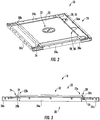
- FIG 2 shows a perspective view of a ceiling 18 of an elevator car 6 according to an exemplary embodiment of the invention.
- the ceiling includes a frame 20 and a cover plate 22 arranged in a closed position, i.e. in a position in which the cover plate 22 is contact with the frame 20.
- Figure 3 depicts a side view of said closed configuration.
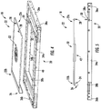
- Figure 4 shows a perspective view of the ceiling 18 shown in Figures 2 and 3 , wherein the cover plate 22 is arranged in an open position, i.e. in a position in which the cover plate 22 is spaced apart from the frame 20.
- Figure 5 depicts a side view of said open configuration.
- the frame 20 comprises a plurality of bars 34a, 34b, 36a, 36b, 38a, 38b, in particular two longitudinal bars 34a, 34b and four crossbars 36a, 36b, 38a, 38b respectively extending between the longitudinal bars 34a, 34b.
- the crossbars 36a, 36b, 38a, 38b in particular extend orthogonally to the longitudinal bars 34a, 34b forming a rectangular frame 20.
- the crossbars 36a, 36b, 38a, 38b include outer crossbars 36a, 36b respectively extending between the ends of the longitudinal bars 34a, 34b; and inner crossbars 38a, 38b, respectively extending between the longitudinal bars 34a, 34b at positions located in between the outer crossbars 36a, 36b.
- the rectangular opening 40 in particular may have the shape of a square.
- the cover plate 22 is configured for closing the opening 40.
- the cover plate 22 approximately has the same dimensions as the opening 40.
- Two apertures 28 are formed at a first end 22a of the cover plate 22 arranged next to a first inner crossbar 38a.
- the first crossbars 36a, 38a and first end 22a of the cover plate 22 are shown on the right sides of Figures 2 to 5 , respectively.
- Fixing elements 30, such as bolts or screws, are provided at the first inner crossbar 38a.
- the positions of the fixing element 30 match with the positions of the apertures 28 formed within the cover plate 22.
- the fixing elements 30 extend through the apertures 28 for fixing the cover plate 22 to the frame 20.
- At least one permanent magnet 24 (see Figures 3 and 5 ) is provided at the opposing second end 22b of the cover plate 22 arranged next to a second inner crossbar 38b.
- the second crossbars 36b, 38b and the second end 22b of the cover plate 22 are shown on the left sides of Figures 2 to 5 .
- At least a portion of the second inner crossbar 38b is made of a magnetic material, e.g. a metal.
- a magnetic material e.g. a metal
- the cover plate 22 is securely fixed to the frame 20 by the fixing elements 30 extending through the apertures 28 at its first end 22a, and by the at least one permanent magnet 24 interacting with the second inner crossbar 38b at its opposing second end 22.
- the position of the cover plate 22 with respect to the frame 20 is set by the fixing elements 30 extending through the apertures 28 formed in the first end 22a of the cover plate 22.
- the position of the permanent magnet(s) 24 with respect to the second inner crossbar 38b is variable to a certain extent. This variability allows compensating for variations and tolerances of the dimensions, in particular the length of the cover plate 22 and/or the distance between the inner crossbars 38a, 38b, while still securely attaching the cover plate 22 to the frame 20.
- At least one permanent magnet may be mounted to the second inner crossbar 38b in order to interact with the second end 22b of the cover plate 22.
- the cover plate 22 is made at least partially of a magnetic material, in particular a metallic material.
- a magnetic material, in particular a metallic material, such as a metallic strip may be provided at least at the second end 22b of the cover plate 22.
- a c-shaped profile 26 is provided at the second end 22b of the cover plate 22.
- the c-shaped profile 26 may be formed integrally with the cover plate 22.
- the c-shaped profile 26 may be attached to the second end 22b of the cover plate 22.
- the c-shaped profile 26 embraces the second inner crossbar 38b. Such a configuration prevents the second end 22b of the cover plate 22 from being lifted from the second inner crossbar 38b without opening/removing the fixing elements 30 at the first inner crossbar 38a.
- opening/removing the fixing elements 30 may be possible from inside and/or from outside the elevator car 6.
- the fixing elements 30 may be provided with locking mechanisms (not shown), such as a mechanical lock or a special type of screws which may be removed only with a special key in order to prevent unauthorized persons from removing the cover plate 22.
- locking mechanisms such as a mechanical lock or a special type of screws which may be removed only with a special key in order to prevent unauthorized persons from removing the cover plate 22.
- the first side 22a of the cover plate 22 may be detached from the first inner crossbar 38a.
- the second side 22b of the cover plate 22 may be separated from the second inner crossbar 38b overcoming the magnetic forces of the permanent magnet(s) 24, and the c-shaped profile 26 may be detached from the second inner crossbar 38b.
- the cover plate 22 may be provided with at least one lighting device 42 configured for lighting the interior space 12 of the elevator car 6.
- the at least one lighting device 42 may be mounted to a bottom side of the cover plate 22 facing the interior space 12, as it is shown in Figure 5 .
- the cover plate 22 may be at least partially transparent.
- the at least one lighting device 42 may be attached to the upper side of the cover plate 22 outside the elevator car 6 facing a transparent portion of the cover plate 22.
- Electrical connectors may be provided at at least one side 22a, 22b of the cover plate 22 for delivering electric energy to the at least one lighting device 42.
- a graphic sign 32 instructing people, such as maintenance personnel, not to step onto the cover plate 22 is provided on the upper side of the cover plate 22.
Landscapes
- Engineering & Computer Science (AREA)
- Structural Engineering (AREA)
- Civil Engineering (AREA)
- Mechanical Engineering (AREA)
- Automation & Control Theory (AREA)
- Cage And Drive Apparatuses For Elevators (AREA)
Abstract
Description
- The invention relates to an elevator car with a removable cover and to an elevator system comprising such an elevator car. The invention further relates to methods of mounting and removing a cover plate to/from an elevator car.
- An elevator system comprises at least one elevator car traveling along a hoistway between a plurality of landings. The elevator car has a ceiling. The ceiling may include a removable cover for closing an opening formed within the ceiling.
- It is desirable to provide an elevator car comprising a ceiling with an opening and a removable cover which allows compensating tolerances of manufacturing so that the opening is reliably closed by the cover.
- According to an exemplary embodiment of the invention, an elevator car comprises a frame. The frame in particular may be arranged horizontally in an upper portion of the elevator car forming part of a ceiling of the elevator car. The elevator car further comprises a removable cover plate. The cover plate includes at least one aperture formed in a first end of the cover plate allowing at least one fixing element extending from the frame to pass through the at least one aperture for fixing the cover plate to the frame. At least one permanent magnet is provided at an opposing second end of the cover plate and/or at a portion of the frame abutting the second end of the cover plate. The at least one permanent magnet is configured for fixing the second end of the cover plate to an adjacent portion of the frame, in particular to a metallic portion of the frame, by means of its magnetic force.
- Exemplary embodiments of the invention further include an elevator system comprising at least one elevator car according to an exemplary embodiment of the invention.
- Exemplary embodiments of the invention also include a method of removing the cover plate comprising a permanent magnet from such an elevator car, wherein the method includes disengaging the at least one fixing element, and removing the cover by disengaging the permanent magnet from the frame.
- In case a permanent magnet is provided at the frame of the elevator car, the method includes disengaging the at least one fixing element and removing the cover plate by disengaging the permanent magnet from the cover plate.
- Exemplary embodiments of the invention further include a method of mounting a cover plate to an elevator car according to an exemplary embodiment of the invention, wherein the method comprises: positioning the cover plate on the frame so that at least one permanent magnet provided at the cover plate attaches to a portion of the frame, and fixing the first end of the cover plate to the frame with at least one fixing element extending through the at least one aperture formed within the cover plate.
- Exemplary embodiments of the invention further include a method of mounting a cover plate to an elevator car according to an exemplary embodiment of the invention, wherein the method comprises: positioning the cover plate on the frame so that at least one permanent magnet provided at the frame attaches to the cover plate, and fixing the first end of the cover plate to the frame with at least one fixing element extending through the at least one aperture formed within the cover plate.
- Exemplary embodiments of the invention allow fixing the cover plate securely to the frame with the position of the cover plate with respect to the frame being set by the fixing elements extending through the apertures formed within the cover plate.
- Since the position of the at least one permanent magnet with respect to the frame is variable, variations and tolerances of the dimensions, such as the length of the cover plate and/or of the frame, may be compensated with the cover plate still being securely attached to the frame.
- A number of optional features are set out in the following. These features may be realized in particular embodiments, alone or in combination with any of the other features.
- A plurality of apertures may be formed within the cover plate, and a plurality of fixing elements may extend from the frame. Providing a plurality of fixing elements in combination with a plurality of apertures allows defining the position of the cover plate with respect to the frame with high accuracy. It in particular allows preventing a rotation of the cover plate around the fixing element(s). It further allows distributing the forces acting onto the fixing elements among a plurality of fixing elements. The apertures and fixing elements may be arranged along a common line.
- The at least one fixing element may include a bolt or screw.
- A plurality of permanent magnets may be provided at an opposing second end of the cover plate and/or at the portion of the frame abutting the second end of the cover plate. The permanent magnets in particular may be arranged along a common line. Providing a plurality of magnets increases the magnetic force fixing the cover plate to the frame.
- The cover plate and/or the frame may be made at least partially of metal in order to allow the magnets to attach to the cover plate or to the frame by their magnetic forces. Other parts of the cover plate and/or of the frame may be made of plastic for reducing the weight of the cover plate or of the frame, respectively.
- The frame may be made at least partially of metal plates, in particular of bent metal plates. Bent metal plates provide a strong frame which is easy to produce at low costs.
- The frame and/or the cover plate may have a rectangular shape, in particular a quadratic shape, respectively.
- The frame in particular may include longitudinal bars extending in a longitudinal direction and crossbars extending between the longitudinal bars. The crossbars in particular may extend orthogonally to the extension of the longitudinal bars so that the longitudinal bars and the crossbars form a rectangular frame. The crossbars may include outer crossbars extending between the ends of the longitudinal bars and inner crossbars extending between the longitudinal bars at positions located in between the outer crossbars.
- The frame also may comprise a plurality of longitudinal bars and a plurality of crossbars forming a chessboard like structure comprising at plurality of openings. One or more of the openings may be covered by a removable cover plate according to an exemplary embodiment of the invention.
- The space(s) formed between the inner crossbars and the space(s) formed between an outer crossbar and an adjacent inner crossbar may be closed by at least one cover plate, respectively. At least one cover plate may be a removable cover plate according to an exemplary embodiment of the invention.
- The second end of the cover plate may be provided with a c-shaped profile embracing a portion of the frame when the cover plate is mounted to the frame in order to prevent lifting the second end of the cover plate from inside the elevator car.
- The method of mounting the cover plate may comprise encompassing a portion of the frame with the c-shaped profile before fixing the first end of the cover plate to the frame by means of the at least one fixing element.
- The method of removing the cover plate may include disengaging the at least one fixing element and detaching the c-shaped profile from the portion of the frame after the at least one fixing element has been disengaged.
- At least one fixing element may be provided with a locking mechanism for preventing an unauthorized removal of the cover plate.
- The cover plate may be at least partially transparent in order to allow light to pass through the cover plate.
- At least one lighting device configured for lighting an interior space of the elevator car may be mounted to the cover plate.
- In the following an exemplary embodiment of the invention is described with reference to the enclosed figures.
-
Figure 1 schematically depicts an elevator system comprising an elevator car according to an exemplary embodiment of the invention. -
Figure 2 depicts a perspective view of a ceiling of an elevator car according to an exemplary embodiment of the invention including a cover plate arranged in a closed position. -
Figure 3 depicts a side view of the configuration shown inFigure 2 . -
Figure 4 depicts a perspective view of the ceiling shown inFigures 2 and 3 with the cover plate being arranged in an open position. -
Figure 5 depicts a side view of the configuration shown inFigure 4 . -
Figure 1 schematically depicts anelevator system 2 comprising an elevator car 6 according to an exemplary embodiment of the invention. - The
elevator system 2 comprises ahoistway 4 extending in a longitudinal direction between a plurality oflandings 8 located on different floors. - The elevator car 6 comprises a
floor 16, aceiling 18 andsidewalls 17 extending between thefloor 16 and theceiling 18 defining aninterior space 12 of the elevator car 6. Only onesidewall 17 is depicted in the schematic illustration ofFig. 1 . - The elevator car 6 is movably suspended within the
hoistway 4 by means of a tension member 3. The tension member 3, for example a rope or belt, is connected to adrive 5, which is configured for driving the tension member 3 in order to move the elevator car 6 along the longitudinal direction / height of thehoistway 4 between the plurality oflandings 8. - Each
landing 8 is provided with a landing door (elevator hoistway door) 10, and the elevator car 6 is provided with a corresponding elevator car door 11 allowing passengers to transfer between alanding 8 and theinterior space 12 of the elevator car 6 when the elevator car 6 is positioned at therespective landing 8. - The exemplary embodiment of the
elevator system 2 shown inFig. 1 employs a 1:1 roping for suspending the elevator car 6. The skilled person, however, easily understands that the type of the roping is not essential for the invention and that different kinds of roping, e.g. a 2:1 roping, may be used as well. Theelevator system 2 may further include a counterweight (not shown) moving concurrently and in opposite direction with respect to the elevator car 6. Alternatively, theelevator system 2 may be anelevator system 2 without a counterweight, as it is shown inFig. 1 . Thedrive 5 may be any form of drive used in the art, e.g. a traction drive, a hydraulic drive or a linear drive. Theelevator system 2 may have a machine room or may be a machine room-less elevator system. Theelevator system 2 may use a tension member 3, as it is shown inFig. 1 , or it may be an elevator system without a tension member 3, comprising e.g. a hydraulic drive or a linear drive (not shown). - The
drive 5 is controlled by anelevator control 15 for moving the elevator car 6 along thehoistway 4 between thedifferent landings 8. - Input to the
elevator control 15 may be provided vialanding control panels 7a, which are provided on eachlanding 8 close to theelevator landing doors 10, and/or via acar operation panel 7b provided inside the elevator car 6. - The
landing control panels 7a and thecar operation panel 7b may be connected to theelevator control 15 by means of electrical lines, which are not shown inFig. 1 , in particular by an electric bus, e.g. a field bus such as a CAN bus, or by means of wireless data connections. - In order to determine the current position of the elevator car 6, the elevator car 6 is provided with a
position sensor 19. Theposition sensor 19 may be arranged at the top of the elevator car 6 as shown inFig. 1 . Alternatively, theposition sensor 19 may be provided at a side of the elevator car 6 or at the bottom, e.g. below afloor 16, of the elevator car 6. -
Figure 2 shows a perspective view of aceiling 18 of an elevator car 6 according to an exemplary embodiment of the invention. The ceiling includes aframe 20 and acover plate 22 arranged in a closed position, i.e. in a position in which thecover plate 22 is contact with theframe 20.Figure 3 depicts a side view of said closed configuration. -
Figure 4 shows a perspective view of theceiling 18 shown inFigures 2 and 3 , wherein thecover plate 22 is arranged in an open position, i.e. in a position in which thecover plate 22 is spaced apart from theframe 20.Figure 5 depicts a side view of said open configuration. - The
frame 20 comprises a plurality ofbars longitudinal bars crossbars longitudinal bars crossbars longitudinal bars rectangular frame 20. - The
crossbars outer crossbars longitudinal bars inner crossbars longitudinal bars outer crossbars - The
inner crossbars longitudinal bars longitudinal bars inner crossbars Fig. 4 ). Therectangular opening 40 in particular may have the shape of a square. - The
cover plate 22 is configured for closing theopening 40. Thecover plate 22 approximately has the same dimensions as theopening 40. - Two
apertures 28 are formed at afirst end 22a of thecover plate 22 arranged next to a firstinner crossbar 38a. Thefirst crossbars first end 22a of thecover plate 22 are shown on the right sides ofFigures 2 to 5 , respectively. - Fixing
elements 30, such as bolts or screws, are provided at the firstinner crossbar 38a. The positions of the fixingelement 30 match with the positions of theapertures 28 formed within thecover plate 22. When thecover plate 22 is mounted to theframe 20, the fixingelements 30 extend through theapertures 28 for fixing thecover plate 22 to theframe 20. - Although two
openings 28 and fixingelements 30 are depicted in the figures, the skilled person will understand that the number of fixingelements 30 and correspondingopenings 28 may be adjusted according to the actual needs. - At least one permanent magnet 24 (see
Figures 3 and5 ) is provided at the opposingsecond end 22b of thecover plate 22 arranged next to a secondinner crossbar 38b. Thesecond crossbars second end 22b of thecover plate 22 are shown on the left sides ofFigures 2 to 5 . - At least a portion of the second
inner crossbar 38b is made of a magnetic material, e.g. a metal. In consequence, when thecover plate 22 is arranged on top of theframe 20, as illustrated inFigures 2 and 3 , the at least onepermanent magnet 24 is attracted by magnetic force to the secondinner crossbar 38b and thereby attached to the secondinner crossbar 38b. - As a result, the
cover plate 22 is securely fixed to theframe 20 by the fixingelements 30 extending through theapertures 28 at itsfirst end 22a, and by the at least onepermanent magnet 24 interacting with the secondinner crossbar 38b at its opposingsecond end 22. - The position of the
cover plate 22 with respect to theframe 20 is set by the fixingelements 30 extending through theapertures 28 formed in thefirst end 22a of thecover plate 22. - The position of the permanent magnet(s) 24 with respect to the second
inner crossbar 38b, however, is variable to a certain extent. This variability allows compensating for variations and tolerances of the dimensions, in particular the length of thecover plate 22 and/or the distance between theinner crossbars cover plate 22 to theframe 20. - Although only a single
permanent magnet 24 is visible inFigures 3 and5 , respectively, the skilled person will understand that a plurality ofpermanent magnets 24 may be provided at thesecond end 22b of thecover plate 22 for increasing the holding force fixing thecover plate 22 to theframe 20. - Alternatively or additionally, at least one permanent magnet (not shown) may be mounted to the second
inner crossbar 38b in order to interact with thesecond end 22b of thecover plate 22. In this case thecover plate 22 is made at least partially of a magnetic material, in particular a metallic material. Alternatively, in case thecover plate 22 is made of a non-magnetic material, e.g. a plastic material, a magnetic material, in particular a metallic material, such as a metallic strip, may be provided at least at thesecond end 22b of thecover plate 22. - In order to prevent an unauthorized removal of the
cover plate 22 from inside the elevator car 6, a c-shapedprofile 26 is provided at thesecond end 22b of thecover plate 22. The c-shapedprofile 26 may be formed integrally with thecover plate 22. Alternatively, the c-shapedprofile 26 may be attached to thesecond end 22b of thecover plate 22. - When the
cover plate 22 is mounted to theframe 20, as depicted inFigures 2 and 3 , the c-shapedprofile 26 embraces the secondinner crossbar 38b. Such a configuration prevents thesecond end 22b of thecover plate 22 from being lifted from the secondinner crossbar 38b without opening/removing the fixingelements 30 at the firstinner crossbar 38a. - I.e. in order to remove the
cover plate 22 from theframe 20, it is necessary to open/remove the fixingelements 30 first. Opening/removing the fixingelements 30 may be possible from inside and/or from outside the elevator car 6. - Optionally, the fixing
elements 30 may be provided with locking mechanisms (not shown), such as a mechanical lock or a special type of screws which may be removed only with a special key in order to prevent unauthorized persons from removing thecover plate 22. - After the fixing
elements 30 have been opened/removed, thefirst side 22a of thecover plate 22 may be detached from the firstinner crossbar 38a. After thefirst side 22a of thecover plate 22 has been detached from the firstinner crossbar 38a, thesecond side 22b of thecover plate 22 may be separated from the secondinner crossbar 38b overcoming the magnetic forces of the permanent magnet(s) 24, and the c-shapedprofile 26 may be detached from the secondinner crossbar 38b. - Optionally, the
cover plate 22 may be provided with at least onelighting device 42 configured for lighting theinterior space 12 of the elevator car 6. - The at least one
lighting device 42 may be mounted to a bottom side of thecover plate 22 facing theinterior space 12, as it is shown inFigure 5 . Alternatively, thecover plate 22 may be at least partially transparent. In such a configuration, the at least onelighting device 42 may be attached to the upper side of thecover plate 22 outside the elevator car 6 facing a transparent portion of thecover plate 22. - Electrical connectors (not shown) may be provided at at least one
side cover plate 22 for delivering electric energy to the at least onelighting device 42. - In the embodiment depicted in
Figures 2 to 5 , agraphic sign 32 instructing people, such as maintenance personnel, not to step onto thecover plate 22 is provided on the upper side of thecover plate 22. - While the invention has been described with reference to exemplary embodiments, it will be understood by those skilled in the art that various changes may be made and equivalents may be substituted for elements thereof without departing from the scope of the invention. In addition, many modifications may be made to adopt a particular situation or material to the teachings of the invention without departing from the essential scope thereof. Therefore, it is intended that the invention is not limited to the particular embodiments disclosed, but that the invention includes all embodiments falling within the scope of the claims.
-
- 2
- elevator system
- 3
- tension member
- 4
- hoistway
- 5
- drive
- 6
- elevator car
- 7a
- landing control panel
- 7b
- car operation panel
- 8
- landing
- 10
- landing door
- 11
- elevator car door
- 12
- interior space of the elevator car
- 15
- elevator control
- 16
- floor of the elevator car
- 17
- sidewall of the elevator car
- 18
- ceiling of the elevator car
- 19
- position sensor
- 20
- frame
- 22
- cover plate
- 24
- permanent magnet
- 26
- c-shaped profile
- 28
- aperture
- 30
- fixing element
- 32
- sign
- 34a, 34b
- longitudinal bars
- 36a, 36b
- outer crossbars
- 38a, 38b
- inner crossbars
- 40
- opening
- 42
- lighting device
Claims (15)
- Elevator car (6) comprising a frame (20) and a removable cover plate (22), the cover plate (22) comprising:at least one aperture (28) formed in a first end (22a) of the cover plate (22) allowing at least one fixing element (30) extending from the frame (20) to pass through the at least one aperture (28) for fixing the cover plate (22) to the frame (20); andat least one permanent magnet (24) provided at an opposing second end (22b) of the cover plate (22) and/or at a portion of the frame (20) abutting the second end (22b) of the cover plate (22);wherein the at least one permanent magnet (24) is configured for fixing the second end (22b) of the cover plate (22) to a portion of the frame (20).
- Elevator car (6) according to claim 1, wherein a plurality of apertures (28) are formed within the cover plate (22), the apertures (28) in particular being arranged along a common line.
- Elevator car (6) according to claim 1 or 2, wherein a plurality of permanent magnets (24) are provided at the second end (22b) of the cover plate (22) and/or at the portion of the frame (20) abutting the second end (22b) of the cover plate (22), the permanent magnets (24) in particular being arranged along a common line.
- Elevator car (6) according to any of the preceding claims, wherein the cover plate (22) and/or the frame (20) are at least partially made of metal and/or plastic.
- Elevator car (6) according to any of the preceding claims, wherein the frame (20) at least partially is made of metal plates, in particular of bent metal plates.
- Elevator car (6) according to any of the preceding claims, wherein the frame (20) and/or the cover plate (22) have a rectangular shape, in particular a quadratic shape, respectively.
- Elevator car (6) according to any of the preceding claims, wherein the second end (22b) of the cover plate (22) is provided with a c-shaped profile (26) configured for embracing a portion of the frame (20) when the cover plate (22) is mounted to the frame (20).
- Elevator car (6) according to any of the preceding claims, wherein the cover plate (22) is at least partially transparent and/or comprises at least one lighting device (42) for lighting an interior space (12) of the elevator car (6).
- Elevator car (6) according to any of the preceding claims, wherein the cover plate (22) is fixed to the frame (20) by at least one fixing element (30).
- Elevator car (6) according to claim 9, wherein the at least one fixing element (30) includes a bolt or a screw.
- Elevator system (2) comprising at least one elevator car (6) according to any of the preceding claims.
- Method of removing the cover plate (22) from an elevator car (6) according to claim 9 or 10, wherein the method includes:disengaging the at least one fixing element (30); andremoving the cover plate (22) by disengaging the permanent magnet (24) from the frame (20) or from the cover plate (22).
- Method according to claim 12, wherein the cover plate (22) comprises a c-shaped profile (26) embracing a portion of the frame (20), and wherein the method includes detaching the c-shaped profile (26) from the portion of the frame (20).
- Method of mounting a cover plate (22) to an elevator car (6) according to any of claims 1 to 10, wherein the method comprises:positioning the cover plate (22) on the frame (20) so that the cover plate (22) is attached to the frame (20) by at least one permanent magnet (24); andfixing the first end (22a) of the cover plate (22) to the frame (20) with at least one fixing element (30) extending through the at least one aperture (28) formed within the cover plate (22).
- Method according to claim 14,
wherein a c-shaped profile (26) is provided at the second end (22b) of the cover plate (22); and
wherein the method comprises encompassing a portion of the frame (20) with the c-shape profile (26) before fixing the first end (22a) of the cover plate (22) to the frame (20).
Priority Applications (4)
| Application Number | Priority Date | Filing Date | Title |
|---|---|---|---|
| EP18169863.0A EP3560876B1 (en) | 2018-04-27 | 2018-04-27 | Elevator car and elevator system |
| ES18169863T ES2887006T3 (en) | 2018-04-27 | 2018-04-27 | Elevator cabin and elevator system |
| US16/394,899 US20190330025A1 (en) | 2018-04-27 | 2019-04-25 | Elevator car and elevator system |
| CN201910342908.3A CN110407066B (en) | 2018-04-27 | 2019-04-26 | Elevator car and elevator system |
Applications Claiming Priority (1)
| Application Number | Priority Date | Filing Date | Title |
|---|---|---|---|
| EP18169863.0A EP3560876B1 (en) | 2018-04-27 | 2018-04-27 | Elevator car and elevator system |
Publications (2)
| Publication Number | Publication Date |
|---|---|
| EP3560876A1 true EP3560876A1 (en) | 2019-10-30 |
| EP3560876B1 EP3560876B1 (en) | 2021-06-02 |
Family
ID=62089643
Family Applications (1)
| Application Number | Title | Priority Date | Filing Date |
|---|---|---|---|
| EP18169863.0A Active EP3560876B1 (en) | 2018-04-27 | 2018-04-27 | Elevator car and elevator system |
Country Status (4)
| Country | Link |
|---|---|
| US (1) | US20190330025A1 (en) |
| EP (1) | EP3560876B1 (en) |
| CN (1) | CN110407066B (en) |
| ES (1) | ES2887006T3 (en) |
Families Citing this family (1)
| Publication number | Priority date | Publication date | Assignee | Title |
|---|---|---|---|---|
| USD1039236S1 (en) * | 2021-04-16 | 2024-08-13 | Nationwide Lifts, Inc. | Unitary elevator car floor |
Citations (4)
| Publication number | Priority date | Publication date | Assignee | Title |
|---|---|---|---|---|
| JPH10139294A (en) * | 1996-11-14 | 1998-05-26 | Otis Elevator Co | Car of side fork type home elevator |
| JP2001316061A (en) * | 2000-05-10 | 2001-11-13 | Mitsubishi Electric Corp | Elevator car ceiling equipment |
| JP5452012B2 (en) * | 2008-11-26 | 2014-03-26 | 三菱電機株式会社 | Sleeve wall holding device and elevator car operation panel |
| JP6194065B1 (en) * | 2016-06-08 | 2017-09-06 | 東芝エレベータ株式会社 | Mirror signage mounting structure and mounting method in an elevator cab |
Family Cites Families (5)
| Publication number | Priority date | Publication date | Assignee | Title |
|---|---|---|---|---|
| US4699251A (en) * | 1986-05-15 | 1987-10-13 | Westinghouse Electric Corp. | Elevator cab |
| EP2123586B1 (en) * | 2007-01-22 | 2016-12-14 | Mitsubishi Electric Corporation | Ceiling device of elevator car |
| FI20116096L (en) * | 2011-11-07 | 2013-05-08 | Kone Corp | Articulating arrangement, roof element and elevator |
| JP6210937B2 (en) * | 2014-06-11 | 2017-10-11 | 株式会社日立製作所 | Elevator equipment |
| CN206232280U (en) * | 2015-12-25 | 2017-06-09 | 东芝电梯株式会社 | Car |
-
2018
- 2018-04-27 EP EP18169863.0A patent/EP3560876B1/en active Active
- 2018-04-27 ES ES18169863T patent/ES2887006T3/en active Active
-
2019
- 2019-04-25 US US16/394,899 patent/US20190330025A1/en not_active Abandoned
- 2019-04-26 CN CN201910342908.3A patent/CN110407066B/en active Active
Patent Citations (4)
| Publication number | Priority date | Publication date | Assignee | Title |
|---|---|---|---|---|
| JPH10139294A (en) * | 1996-11-14 | 1998-05-26 | Otis Elevator Co | Car of side fork type home elevator |
| JP2001316061A (en) * | 2000-05-10 | 2001-11-13 | Mitsubishi Electric Corp | Elevator car ceiling equipment |
| JP5452012B2 (en) * | 2008-11-26 | 2014-03-26 | 三菱電機株式会社 | Sleeve wall holding device and elevator car operation panel |
| JP6194065B1 (en) * | 2016-06-08 | 2017-09-06 | 東芝エレベータ株式会社 | Mirror signage mounting structure and mounting method in an elevator cab |
Also Published As
| Publication number | Publication date |
|---|---|
| EP3560876B1 (en) | 2021-06-02 |
| US20190330025A1 (en) | 2019-10-31 |
| CN110407066B (en) | 2021-07-16 |
| CN110407066A (en) | 2019-11-05 |
| ES2887006T3 (en) | 2021-12-21 |
Similar Documents
| Publication | Publication Date | Title |
|---|---|---|
| US10589964B2 (en) | Elevator car, elevator system and method of checking, maintaining and/or repairing an elevator system | |
| EP3319896B1 (en) | Handrail for an elevator car including a locking mechanism | |
| CN107787299B (en) | Elevator with linear motor | |
| ES2441443T3 (en) | Lift machine support | |
| CN109476462B (en) | Elevator device | |
| US20180111797A1 (en) | Elevator car wall panels | |
| US20170362064A1 (en) | Elevator Car and Elevator System | |
| US20190119074A1 (en) | Elevator arrangement for safe maintenance work | |
| ES2441444T3 (en) | Elevator system that includes electronic control systems supported on an elevator machine support | |
| JPWO2018079032A1 (en) | Elevator landing door open detection device and elevator | |
| WO2013012249A2 (en) | Automatic cab door opening/closing device installed in section within elevator entrance | |
| CN101134548A (en) | Lift facility with cabin and counterweight and method for arranging a lift facility | |
| EP3560876B1 (en) | Elevator car and elevator system | |
| KR20220162692A (en) | rail system | |
| KR101216428B1 (en) | elevator system and installation method | |
| EP3795527A1 (en) | Elevator car frame | |
| AU2016208723A1 (en) | Elevator | |
| CN102556811A (en) | Automatic protecting device for hand-operated landing doors of lifters or cargo lifts | |
| EP3299329B1 (en) | Elevator car | |
| EP3056462A1 (en) | Elevator door arrangement | |
| WO2010016739A2 (en) | Hoistway door separation preventing device for a lift | |
| EP4477607A1 (en) | Brake circuit access from landing | |
| KR200472877Y1 (en) | Door open-close apparatuus of elevator | |
| WO2019172560A1 (en) | Elevator safety device for preventing pinching injuries of hand by using safety shoe | |
| KR20060084156A (en) | Platform door assembly of elevator system |
Legal Events
| Date | Code | Title | Description |
|---|---|---|---|
| PUAI | Public reference made under article 153(3) epc to a published international application that has entered the european phase |
Free format text: ORIGINAL CODE: 0009012 |
|
| STAA | Information on the status of an ep patent application or granted ep patent |
Free format text: STATUS: THE APPLICATION HAS BEEN PUBLISHED |
|
| AK | Designated contracting states |
Kind code of ref document: A1 Designated state(s): AL AT BE BG CH CY CZ DE DK EE ES FI FR GB GR HR HU IE IS IT LI LT LU LV MC MK MT NL NO PL PT RO RS SE SI SK SM TR |
|
| AX | Request for extension of the european patent |
Extension state: BA ME |
|
| STAA | Information on the status of an ep patent application or granted ep patent |
Free format text: STATUS: REQUEST FOR EXAMINATION WAS MADE |
|
| 17P | Request for examination filed |
Effective date: 20200206 |
|
| RBV | Designated contracting states (corrected) |
Designated state(s): AL AT BE BG CH CY CZ DE DK EE ES FI FR GB GR HR HU IE IS IT LI LT LU LV MC MK MT NL NO PL PT RO RS SE SI SK SM TR |
|
| GRAP | Despatch of communication of intention to grant a patent |
Free format text: ORIGINAL CODE: EPIDOSNIGR1 |
|
| STAA | Information on the status of an ep patent application or granted ep patent |
Free format text: STATUS: GRANT OF PATENT IS INTENDED |
|
| INTG | Intention to grant announced |
Effective date: 20210204 |
|
| GRAS | Grant fee paid |
Free format text: ORIGINAL CODE: EPIDOSNIGR3 |
|
| GRAA | (expected) grant |
Free format text: ORIGINAL CODE: 0009210 |
|
| STAA | Information on the status of an ep patent application or granted ep patent |
Free format text: STATUS: THE PATENT HAS BEEN GRANTED |
|
| REG | Reference to a national code |
Ref country code: CH Ref legal event code: EP |
|
| AK | Designated contracting states |
Kind code of ref document: B1 Designated state(s): AL AT BE BG CH CY CZ DE DK EE ES FI FR GB GR HR HU IE IS IT LI LT LU LV MC MK MT NL NO PL PT RO RS SE SI SK SM TR |
|
| REG | Reference to a national code |
Ref country code: GB Ref legal event code: FG4D |
|
| REG | Reference to a national code |
Ref country code: AT Ref legal event code: REF Ref document number: 1398284 Country of ref document: AT Kind code of ref document: T Effective date: 20210615 |
|
| REG | Reference to a national code |
Ref country code: IE Ref legal event code: FG4D |
|
| REG | Reference to a national code |
Ref country code: DE Ref legal event code: R096 Ref document number: 602018017893 Country of ref document: DE |
|
| REG | Reference to a national code |
Ref country code: LT Ref legal event code: MG9D |
|
| PG25 | Lapsed in a contracting state [announced via postgrant information from national office to epo] |
Ref country code: BG Free format text: LAPSE BECAUSE OF FAILURE TO SUBMIT A TRANSLATION OF THE DESCRIPTION OR TO PAY THE FEE WITHIN THE PRESCRIBED TIME-LIMIT Effective date: 20210902 Ref country code: HR Free format text: LAPSE BECAUSE OF FAILURE TO SUBMIT A TRANSLATION OF THE DESCRIPTION OR TO PAY THE FEE WITHIN THE PRESCRIBED TIME-LIMIT Effective date: 20210602 Ref country code: LT Free format text: LAPSE BECAUSE OF FAILURE TO SUBMIT A TRANSLATION OF THE DESCRIPTION OR TO PAY THE FEE WITHIN THE PRESCRIBED TIME-LIMIT Effective date: 20210602 Ref country code: FI Free format text: LAPSE BECAUSE OF FAILURE TO SUBMIT A TRANSLATION OF THE DESCRIPTION OR TO PAY THE FEE WITHIN THE PRESCRIBED TIME-LIMIT Effective date: 20210602 |
|
| REG | Reference to a national code |
Ref country code: NL Ref legal event code: MP Effective date: 20210602 |
|
| REG | Reference to a national code |
Ref country code: AT Ref legal event code: MK05 Ref document number: 1398284 Country of ref document: AT Kind code of ref document: T Effective date: 20210602 |
|
| PG25 | Lapsed in a contracting state [announced via postgrant information from national office to epo] |
Ref country code: SE Free format text: LAPSE BECAUSE OF FAILURE TO SUBMIT A TRANSLATION OF THE DESCRIPTION OR TO PAY THE FEE WITHIN THE PRESCRIBED TIME-LIMIT Effective date: 20210602 Ref country code: RS Free format text: LAPSE BECAUSE OF FAILURE TO SUBMIT A TRANSLATION OF THE DESCRIPTION OR TO PAY THE FEE WITHIN THE PRESCRIBED TIME-LIMIT Effective date: 20210602 Ref country code: PL Free format text: LAPSE BECAUSE OF FAILURE TO SUBMIT A TRANSLATION OF THE DESCRIPTION OR TO PAY THE FEE WITHIN THE PRESCRIBED TIME-LIMIT Effective date: 20210602 Ref country code: LV Free format text: LAPSE BECAUSE OF FAILURE TO SUBMIT A TRANSLATION OF THE DESCRIPTION OR TO PAY THE FEE WITHIN THE PRESCRIBED TIME-LIMIT Effective date: 20210602 Ref country code: NO Free format text: LAPSE BECAUSE OF FAILURE TO SUBMIT A TRANSLATION OF THE DESCRIPTION OR TO PAY THE FEE WITHIN THE PRESCRIBED TIME-LIMIT Effective date: 20210902 Ref country code: GR Free format text: LAPSE BECAUSE OF FAILURE TO SUBMIT A TRANSLATION OF THE DESCRIPTION OR TO PAY THE FEE WITHIN THE PRESCRIBED TIME-LIMIT Effective date: 20210903 |
|
| REG | Reference to a national code |
Ref country code: ES Ref legal event code: FG2A Ref document number: 2887006 Country of ref document: ES Kind code of ref document: T3 Effective date: 20211221 |
|
| PG25 | Lapsed in a contracting state [announced via postgrant information from national office to epo] |
Ref country code: SM Free format text: LAPSE BECAUSE OF FAILURE TO SUBMIT A TRANSLATION OF THE DESCRIPTION OR TO PAY THE FEE WITHIN THE PRESCRIBED TIME-LIMIT Effective date: 20210602 Ref country code: SK Free format text: LAPSE BECAUSE OF FAILURE TO SUBMIT A TRANSLATION OF THE DESCRIPTION OR TO PAY THE FEE WITHIN THE PRESCRIBED TIME-LIMIT Effective date: 20210602 Ref country code: EE Free format text: LAPSE BECAUSE OF FAILURE TO SUBMIT A TRANSLATION OF THE DESCRIPTION OR TO PAY THE FEE WITHIN THE PRESCRIBED TIME-LIMIT Effective date: 20210602 Ref country code: NL Free format text: LAPSE BECAUSE OF FAILURE TO SUBMIT A TRANSLATION OF THE DESCRIPTION OR TO PAY THE FEE WITHIN THE PRESCRIBED TIME-LIMIT Effective date: 20210602 Ref country code: PT Free format text: LAPSE BECAUSE OF FAILURE TO SUBMIT A TRANSLATION OF THE DESCRIPTION OR TO PAY THE FEE WITHIN THE PRESCRIBED TIME-LIMIT Effective date: 20211004 Ref country code: RO Free format text: LAPSE BECAUSE OF FAILURE TO SUBMIT A TRANSLATION OF THE DESCRIPTION OR TO PAY THE FEE WITHIN THE PRESCRIBED TIME-LIMIT Effective date: 20210602 Ref country code: AT Free format text: LAPSE BECAUSE OF FAILURE TO SUBMIT A TRANSLATION OF THE DESCRIPTION OR TO PAY THE FEE WITHIN THE PRESCRIBED TIME-LIMIT Effective date: 20210602 Ref country code: CZ Free format text: LAPSE BECAUSE OF FAILURE TO SUBMIT A TRANSLATION OF THE DESCRIPTION OR TO PAY THE FEE WITHIN THE PRESCRIBED TIME-LIMIT Effective date: 20210602 |
|
| REG | Reference to a national code |
Ref country code: DE Ref legal event code: R097 Ref document number: 602018017893 Country of ref document: DE |
|
| PLBE | No opposition filed within time limit |
Free format text: ORIGINAL CODE: 0009261 |
|
| STAA | Information on the status of an ep patent application or granted ep patent |
Free format text: STATUS: NO OPPOSITION FILED WITHIN TIME LIMIT |
|
| PG25 | Lapsed in a contracting state [announced via postgrant information from national office to epo] |
Ref country code: DK Free format text: LAPSE BECAUSE OF FAILURE TO SUBMIT A TRANSLATION OF THE DESCRIPTION OR TO PAY THE FEE WITHIN THE PRESCRIBED TIME-LIMIT Effective date: 20210602 |
|
| 26N | No opposition filed |
Effective date: 20220303 |
|
| PG25 | Lapsed in a contracting state [announced via postgrant information from national office to epo] |
Ref country code: AL Free format text: LAPSE BECAUSE OF FAILURE TO SUBMIT A TRANSLATION OF THE DESCRIPTION OR TO PAY THE FEE WITHIN THE PRESCRIBED TIME-LIMIT Effective date: 20210602 |
|
| PG25 | Lapsed in a contracting state [announced via postgrant information from national office to epo] |
Ref country code: IT Free format text: LAPSE BECAUSE OF FAILURE TO SUBMIT A TRANSLATION OF THE DESCRIPTION OR TO PAY THE FEE WITHIN THE PRESCRIBED TIME-LIMIT Effective date: 20210602 |
|
| REG | Reference to a national code |
Ref country code: CH Ref legal event code: PL |
|
| GBPC | Gb: european patent ceased through non-payment of renewal fee |
Effective date: 20220427 |
|
| REG | Reference to a national code |
Ref country code: BE Ref legal event code: MM Effective date: 20220430 |
|
| PG25 | Lapsed in a contracting state [announced via postgrant information from national office to epo] |
Ref country code: MC Free format text: LAPSE BECAUSE OF FAILURE TO SUBMIT A TRANSLATION OF THE DESCRIPTION OR TO PAY THE FEE WITHIN THE PRESCRIBED TIME-LIMIT Effective date: 20210602 Ref country code: LU Free format text: LAPSE BECAUSE OF NON-PAYMENT OF DUE FEES Effective date: 20220427 Ref country code: LI Free format text: LAPSE BECAUSE OF NON-PAYMENT OF DUE FEES Effective date: 20220430 Ref country code: GB Free format text: LAPSE BECAUSE OF NON-PAYMENT OF DUE FEES Effective date: 20220427 Ref country code: CH Free format text: LAPSE BECAUSE OF NON-PAYMENT OF DUE FEES Effective date: 20220430 |
|
| PG25 | Lapsed in a contracting state [announced via postgrant information from national office to epo] |
Ref country code: BE Free format text: LAPSE BECAUSE OF NON-PAYMENT OF DUE FEES Effective date: 20220430 |
|
| PG25 | Lapsed in a contracting state [announced via postgrant information from national office to epo] |
Ref country code: IE Free format text: LAPSE BECAUSE OF NON-PAYMENT OF DUE FEES Effective date: 20220427 |
|
| PG25 | Lapsed in a contracting state [announced via postgrant information from national office to epo] |
Ref country code: HU Free format text: LAPSE BECAUSE OF FAILURE TO SUBMIT A TRANSLATION OF THE DESCRIPTION OR TO PAY THE FEE WITHIN THE PRESCRIBED TIME-LIMIT; INVALID AB INITIO Effective date: 20180427 |
|
| PG25 | Lapsed in a contracting state [announced via postgrant information from national office to epo] |
Ref country code: MK Free format text: LAPSE BECAUSE OF FAILURE TO SUBMIT A TRANSLATION OF THE DESCRIPTION OR TO PAY THE FEE WITHIN THE PRESCRIBED TIME-LIMIT Effective date: 20210602 Ref country code: CY Free format text: LAPSE BECAUSE OF FAILURE TO SUBMIT A TRANSLATION OF THE DESCRIPTION OR TO PAY THE FEE WITHIN THE PRESCRIBED TIME-LIMIT Effective date: 20210602 |
|
| PG25 | Lapsed in a contracting state [announced via postgrant information from national office to epo] |
Ref country code: TR Free format text: LAPSE BECAUSE OF FAILURE TO SUBMIT A TRANSLATION OF THE DESCRIPTION OR TO PAY THE FEE WITHIN THE PRESCRIBED TIME-LIMIT Effective date: 20210602 |
|
| PG25 | Lapsed in a contracting state [announced via postgrant information from national office to epo] |
Ref country code: MT Free format text: LAPSE BECAUSE OF FAILURE TO SUBMIT A TRANSLATION OF THE DESCRIPTION OR TO PAY THE FEE WITHIN THE PRESCRIBED TIME-LIMIT Effective date: 20210602 |
|
| PGFP | Annual fee paid to national office [announced via postgrant information from national office to epo] |
Ref country code: DE Payment date: 20250319 Year of fee payment: 8 |
|
| PGFP | Annual fee paid to national office [announced via postgrant information from national office to epo] |
Ref country code: ES Payment date: 20250502 Year of fee payment: 8 |
|
| PGFP | Annual fee paid to national office [announced via postgrant information from national office to epo] |
Ref country code: FR Payment date: 20260320 Year of fee payment: 9 |