EP3560806A1 - Transport device - Google Patents
Transport device Download PDFInfo
- Publication number
- EP3560806A1 EP3560806A1 EP16924616.2A EP16924616A EP3560806A1 EP 3560806 A1 EP3560806 A1 EP 3560806A1 EP 16924616 A EP16924616 A EP 16924616A EP 3560806 A1 EP3560806 A1 EP 3560806A1
- Authority
- EP
- European Patent Office
- Prior art keywords
- storage case
- suspension device
- side suspension
- elastic members
- outer casing
- Prior art date
- Legal status (The legal status is an assumption and is not a legal conclusion. Google has not performed a legal analysis and makes no representation as to the accuracy of the status listed.)
- Granted
Links
Images









Classifications
-
- B—PERFORMING OPERATIONS; TRANSPORTING
- B62—LAND VEHICLES FOR TRAVELLING OTHERWISE THAN ON RAILS
- B62J—CYCLE SADDLES OR SEATS; AUXILIARY DEVICES OR ACCESSORIES SPECIALLY ADAPTED TO CYCLES AND NOT OTHERWISE PROVIDED FOR, e.g. ARTICLE CARRIERS OR CYCLE PROTECTORS
- B62J9/00—Containers specially adapted for cycles, e.g. panniers or saddle bags
- B62J9/20—Containers specially adapted for cycles, e.g. panniers or saddle bags attached to the cycle as accessories
- B62J9/23—Containers specially adapted for cycles, e.g. panniers or saddle bags attached to the cycle as accessories above or alongside the rear wheel
-
- B—PERFORMING OPERATIONS; TRANSPORTING
- B62—LAND VEHICLES FOR TRAVELLING OTHERWISE THAN ON RAILS
- B62J—CYCLE SADDLES OR SEATS; AUXILIARY DEVICES OR ACCESSORIES SPECIALLY ADAPTED TO CYCLES AND NOT OTHERWISE PROVIDED FOR, e.g. ARTICLE CARRIERS OR CYCLE PROTECTORS
- B62J7/00—Luggage carriers
- B62J7/02—Luggage carriers characterised by the arrangement thereof on cycles
- B62J7/04—Luggage carriers characterised by the arrangement thereof on cycles arranged above or behind the rear wheel
-
- B—PERFORMING OPERATIONS; TRANSPORTING
- B62—LAND VEHICLES FOR TRAVELLING OTHERWISE THAN ON RAILS
- B62J—CYCLE SADDLES OR SEATS; AUXILIARY DEVICES OR ACCESSORIES SPECIALLY ADAPTED TO CYCLES AND NOT OTHERWISE PROVIDED FOR, e.g. ARTICLE CARRIERS OR CYCLE PROTECTORS
- B62J9/00—Containers specially adapted for cycles, e.g. panniers or saddle bags
- B62J9/20—Containers specially adapted for cycles, e.g. panniers or saddle bags attached to the cycle as accessories
- B62J9/28—Containers specially adapted for cycles, e.g. panniers or saddle bags attached to the cycle as accessories specially adapted for delivery service, e.g. insulated boxes
-
- B—PERFORMING OPERATIONS; TRANSPORTING
- B65—CONVEYING; PACKING; STORING; HANDLING THIN OR FILAMENTARY MATERIAL
- B65D—CONTAINERS FOR STORAGE OR TRANSPORT OF ARTICLES OR MATERIALS, e.g. BAGS, BARRELS, BOTTLES, BOXES, CANS, CARTONS, CRATES, DRUMS, JARS, TANKS, HOPPERS, FORWARDING CONTAINERS; ACCESSORIES, CLOSURES, OR FITTINGS THEREFOR; PACKAGING ELEMENTS; PACKAGES
- B65D81/00—Containers, packaging elements, or packages, for contents presenting particular transport or storage problems, or adapted to be used for non-packaging purposes after removal of contents
- B65D81/02—Containers, packaging elements, or packages, for contents presenting particular transport or storage problems, or adapted to be used for non-packaging purposes after removal of contents specially adapted to protect contents from mechanical damage
- B65D81/05—Containers, packaging elements, or packages, for contents presenting particular transport or storage problems, or adapted to be used for non-packaging purposes after removal of contents specially adapted to protect contents from mechanical damage maintaining contents at spaced relation from package walls, or from other contents
- B65D81/07—Containers, packaging elements, or packages, for contents presenting particular transport or storage problems, or adapted to be used for non-packaging purposes after removal of contents specially adapted to protect contents from mechanical damage maintaining contents at spaced relation from package walls, or from other contents using resilient suspension means
-
- B—PERFORMING OPERATIONS; TRANSPORTING
- B62—LAND VEHICLES FOR TRAVELLING OTHERWISE THAN ON RAILS
- B62K—CYCLES; CYCLE FRAMES; CYCLE STEERING DEVICES; RIDER-OPERATED TERMINAL CONTROLS SPECIALLY ADAPTED FOR CYCLES; CYCLE AXLE SUSPENSIONS; CYCLE SIDECARS, FORECARS, OR THE LIKE
- B62K2201/00—Springs used in cycle frames or parts thereof
- B62K2201/02—Rubber springs
Definitions
- the present invention relates to a conveying apparatus for conveying a stored article using a traveling structure.
- a known conveying apparatus is disposed in a traveling structure, such as a bicycle, a scooter, or an automobile, and conveys a stored article, such as food, stored thereinside through the traveling structure (see, for example, Patent Literature 1, Patent Literature 2, and Patent Literature 3).
- Such a conveying apparatus is used in, for example, home delivery to an orderer from a store that has received the order or a distribution center and is disposed on a cargo deck of, for example, a bicycle or a scooter.
- the stored article because of being conveyed by the traveling structure, is subjected to external force due to, for example, vibration and acceleration and deceleration, while the traveling structure is traveling.
- the external force to be applied to the stored article tends to be large particularly during traveling along a slope, in addition to sudden acceleration and sudden deceleration.
- the stored article is moved or swayed inside the conveying apparatus when an external force is applied to the stored article during traveling. If the stored article is moved or swayed excessively and if the stored article is food in particular, the food may spill from a container thereof or an arrangement thereof may change.
- a conveying apparatus includes: an outer casing for disposing the conveying apparatus on a traveling structure; a storage case that is disposed inside the outer casing and that allows a stored article to be placed therein and removed therefrom from above; a plurality of stretchable elastic members that are spaced apart from each other in a crosswise direction and each of which includes a bridging portion that bridges between front and rear ends of the outer casing in a traveling direction of the traveling structure; and a plurality of suspension devices that are spaced apart from each other at least in a fore-aft direction and each of which includes an upper end assuming a supported portion that is supported slidably on the elastic member and a lower end assuming a supporting portion that supports the storage case.
- the suspension devices are supported by the elastic members pivotally rockably about the supported portions
- the storage case is supported by the suspension devices pivotally rockably about the supporting portions
- the storage case is suspended on the elastic members by the suspension devices under a condition in which a gap is available between the storage case and the outer casing.
- the configuration allows the storage case to be moved in the fore-aft direction relative to the outer casing and to be rocked about the supported portions during traveling of the traveling structure.
- the elastic members are disposed in parallel with each other.
- the configuration results in a distance between the elastic members remaining constant at any position in the fore-aft direction.
- the storage case is hard to incline with respect to the vertical direction.
- the elastic members include two elastic members, and the bridging portions of the two elastic members are disposed at positions immediately above both ends in the crosswise direction, respectively, of the storage case.
- the configuration provides a greater distance between the elastic members, so that the storage case is held in a steady state in the crosswise direction.
- the suspension devices each include a connecting portion that connects between the supported portion and the supporting portion and the connecting portions are disposed between the storage case and the outer casing.
- the configuration reduces a space taken up by the suspension devices inside the storage case.
- the conveying apparatus further includes a tension adjustment structure that adjusts tension in the elastic members.
- the configuration enables the position at which the storage case is suspended with respect to the outer casing and a stretch state of the elastic members during traveling of the traveling structure to be varied through adjustment of the tension in the elastic members.
- each of both ends of each of the elastic members in a direction in which the elastic member is stretched assumes an attached portion to be attached on the traveling structure.
- the configuration allows the both ends of each of the elastic members to be attached to the traveling structure to thereby enable the bridging portions to bridge between front and rear ends of the outer casing.
- the storage case while the traveling structure is traveling, the storage case is movable in the fore-aft direction relative to the outer casing and is pivotally rockable about the supported portions.
- the storage case is moved in a direction in which the storage case is displaced in the vertical direction regardless of posture of the outer casing, so that a steady storage condition can be achieved for the stored article during traveling of the traveling structure.
- the conveying apparatus is disposed on a cargo deck of a bicycle as a traveling structure.
- the conveying apparatus may nonetheless be disposed on, for example, a cargo deck of another traveling structure of a two-wheeled, three-wheeled, or four-wheeled motorcycle or automobile, and the like.
- This traveling structure 100 includes a vehicle body 101, a front wheel 102, and a rear wheel 103.
- the vehicle body 101 includes a handlebar and a saddle, and the like.
- the front wheel 102 and the rear wheel 103 are supported by the vehicle body 101.
- a cargo deck 104 which is coupled with the vehicle body 101, is disposed superior to the rear wheel 103.
- the cargo deck 104 includes a mounting stand 105 and mounting protrusions 106, 106, ...
- the mounting stand 105 is positioned in a horizontal state.
- the mounting protrusions 106, 106, ... protrude downwardly from a lower surface of the mounting stand 105.
- the mounting protrusions 106, 106, ... are spaced away from each other in a crosswise direction and a fore-aft direction.
- the mounting protrusions 106, 106, ... comprise, for example, four mounting protrusions, two each being disposed at front and rear on either side in the crosswise direction.
- This conveying apparatus 1 includes an outer casing 2 and a storage case 3.
- the outer casing 2 includes, for example, a box-shaped case portion 4 and a cover portion 5.
- the case portion 4 is open upwardly.
- the cover portion 5 opens and closes an opening 4a in the case portion 4.
- the outer casing 2 assumes a structure for disposing the conveying apparatus 1 on the cargo deck 104.
- the case portion 4 includes a bottom surface panel portion 6 and an outer peripheral panel portion 7.
- the bottom surface panel portion 6 is placed on the mounting stand 105 of the traveling structure 100.
- the outer peripheral panel portion 7 protrudes upwardly from an outer peripheral portion of the bottom surface panel portion 6.
- the outer peripheral panel portion 7 is composed of a front surface panel portion 8, a rear surface panel portion 9, and a pair of side surface panel portions 10, 10.
- the front surface panel portion 8 and the rear surface panel portion 9 are disposed to be spaced apart in the fore-aft direction.
- the side surface panel portions 10, 10 are disposed on either side in the crosswise direction.
- the front surface panel portion 8 and the rear surface panel portion 9 have locking recesses 8a, 8a, 9a, 9a formed in respective upper end portions thereof.
- the locking recesses 8a, 8a, 9a, 9a are open upwardly.
- the locking recesses 8a, 8a and the locking recesses 9a, 9a are each spaced apart from each other in the crosswise direction.
- the locking recesses 8a, 8a, 9a, 9a are formed at positions closer to either lateral side.
- the cover portion 5 is coupled with an upper end portion of one of the side surface panel portions 10, 10 rotatably (openably) via hinges 11, 11, for example.
- the cover portion 5 is pivotally rotated about the hinges 11, 11 to thereby open or close the opening 4a in the case portion 4.
- cover portion 5 may not have to be coupled with the case portion 4.
- the cover portion 5 may, for example, be configured so as to be removed from the case portion 4 under a condition in which the opening 4a in the case portion 4 is not closed.
- the storage case 3 is formed, for example, into a box shape opening upwardly and has an outline shape smaller than the outer casing 2.
- the storage case 3 is disposed under a condition in which the storage case 3 is suspended inside the outer casing 2.
- the storage case 3 includes a bottom surface portion 12 and an outer peripheral surface portion 13.
- the bottom surface portion 12 has a plate shape facing in a vertical direction.
- the outer peripheral surface portion 13 protrudes upwardly from an outer peripheral portion of the bottom surface portion 12.
- the outer peripheral surface portion 13 is composed of a front surface portion 14 and a rear surface portion 15, and a pair of side surface portions 16, 16.
- the front surface portion 14 and the rear surface portion 15 are disposed to be spaced apart in the fore-aft direction.
- the side surface portions 16, 16 are disposed on either side in the crosswise direction.
- the front surface portion 14 and the rear surface portion 15 have supported holes 14a, 14a, 15a, 15a formed in positions closer to respective upper end portions thereof.
- the supported holes 14a, 14a and the supported holes 15a, 15a are each spaced apart from each other in the crosswise direction.
- the supported holes 14a, 14a, 15a, 15a are formed at positions closer to either lateral side.
- the storage case 3 has an internal space defined as a storage space 3a.
- a stored article 50 such as food, is stored in the storage space 3a.
- the storage case 3 is suspended on elastic members 17, 17 via front-side suspension devices 18, 18 and rear-side suspension devices 19, 19.
- the elastic members 17, 17 are each, for example, a strap-shaped rubber member including annular attached portions 20, 20 disposed on both ends in a stretching direction (longitudinal direction). Each of the elastic members 17, 17 includes extended portions 21, 21 and a bridging portion 22. Out of a portion extending between the attached portions 20, 20, the extended portions 21, 21 are continuous from the respective attached portions 20, 20 and a portion between the extended portions 21, 21 assumes the bridging portion 22.
- Each of the elastic members 17, 17 is formed to have a curved, for example, circular outer peripheral surface excepting the attached portions 20, 20.
- Each of the front-side suspension devices 18, 18 includes, for example, a linear connecting portion 18a, an arcuate (hook-shaped) supported portion 18b, and an arcuate (hook-shaped) supporting portion 18c.
- the supported portion 18b joins an upper end of the connecting portion 18a.
- the supporting portion 18c joins a lower end of the connecting portion 18a.
- the supported portion 18b has an axis orthogonal to an axis of the supporting portion 18c.
- Each of the rear-side suspension devices 19, 19 includes, for example, a linear connecting portion 19a, an arcuate (hook-shaped) supported portion 19b, and an arcuate (hook-shaped) supporting portion 19c.
- the supported portion 19b joins an upper end of the connecting portion 19a.
- the supporting portion 19c joins a lower end of the connecting portion 19a.
- the supported portion 19b has an axis orthogonal to an axis of the supporting portion 19c.
- the attached portions 20, 20, ... are mounted on the respective mounting protrusions 106, 106, ... of the elastic members 17, 17.
- the cover portion 5 of the outer casing 2 is open and the elastic members 17, 17 are mounted on the outer casing 2 by having portions thereof bridging between the front surface panel portion 8 and the rear surface panel portion 9.
- the portion of the elastic member 17 bridging between the front surface panel portion 8 and the rear surface panel portion 9 functions as the bridging portion 22 and the portion of the elastic member 17 between the bridging portion 22 and the attached portion 20, 20 functions as the extended portion 21, 21.
- Both ends of the bridging portion 22 of the elastic member 17 are inserted in the locking recesses 8a and 9a in the front surface panel portion 8 and the rear surface panel portion 9, respectively.
- the insertion of the both ends of the bridging portion 22 of the elastic member 17 in the locking recesses 8a and 9a in the front surface panel portion 8 and the rear surface panel portion 9, respectively, causes the elastic member 17 to be positioned correctly in the crosswise direction relative to the outer casing 2, so that the elastic member 17 is restricted from being displaced in the crosswise direction.
- the elastic members 17, 17, when mounted in the outer casing 2, are placed in a condition in which the elastic members 17, 17 extend in parallel with each other.
- the elastic members 17, 17 are mounted in the outer casing 2 by being stretched to be elastically deformed.
- the mounting of the elastic members 17, 17 under a condition of being stretched in the outer casing 2 causes the elastic members 17, 17 to exert an external force on the case portion 4 of the outer casing 2.
- the bottom surface panel portion 6 is pressed up against the mounting stand 105 from above, so that a steady mounting condition can be achieved with respect to the cargo deck 104 of the conveying apparatus 1.
- the conveying apparatus 1 is mounted on the cargo deck 104 by the elastic members 17, 17.
- the elastic members 17, 17 serve a function of mounting the conveying apparatus 1 on the cargo deck 104, in addition to a function of suspending the storage case 3, so that functionality of the elastic members 17, 17 can be enhanced.
- the elastic members 17, 17's serving the function of suspending the storage case 3 and the function of mounting the conveying apparatus 1 on the cargo deck 104 eliminates the need for additional member or work allocated to the mounting of the conveying apparatus 1 on the cargo deck 104.
- the mounting of the conveying apparatus 1 can be easily performed through simple steps without involving an increased number of parts used.
- the supported portion 18b of the front-side suspension device 18 and the supported portion 19b of the rear-side suspension device 19 are assembled with the elastic member 17.
- the supporting portions 18c, 18c of the front-side suspension devices 18, 18 and the supporting portions 19c, 19c of the rear-side suspension devices 19, 19 are inserted in the supported holes 14a, 14a and the supported holes 15a, 15a, respectively, in the storage case 3, which is disposed inside the outer casing 2.
- the storage case 3 is suspended on the elastic members 17, 17, which are mounted in the outer casing 2, by the front-side suspension devices 18, 18 and the rear-side suspension devices 19, 19.
- the supporting portion 18c of the front-side suspension device 18 and the supporting portion 19c of the rear-side suspension device 19 are inserted in the supported hole 14a and the supported hole 15a, respectively, from a front surface side of the front surface portion 14 and a rear surface side of the rear surface portion 15, respectively.
- the insertion of the supporting portions 18c and 19c in the supported holes 14a and 15a from the front surface side of the front surface portion 14 and the rear surface side of the rear surface portion 15 causes the connecting portions 18a and 19a to be disposed between the outer peripheral surface portion 13 of the storage case 3 and the outer peripheral panel portion 7 of the outer casing 2.
- the foregoing configuration results in a reduced space taken up by the front-side suspension device 18 and the rear-side suspension device 19 in the storage space 3a of the storage case 3, compared with a configuration in which the supporting portions 18c and 19c are inserted in the supported holes 14a and 15a from a rear surface side of the front surface portion 14 and a front surface side of the rear surface portion 15.
- the connecting portions 18a and 19a are disposed between the storage case 3 and the outer casing 2, the front-side suspension device 18 and the rear-side suspension device 19 do not serve as a hindrance for the stored article 50 to be placed in, and removed from, the storage case 3.
- placement of the stored article 50 in, and removal of the stored article 50 from, the storage space 3a of the storage case 3 can be performed easily.
- the insertion of the supporting portions 18c and 19c in the supported holes 14a and 15a from the front surface side of the front surface portion 14 and the rear surface side of the rear surface portion 15 provides a greater distance between the front-side suspension device 18 and the rear-side suspension device 19, compared with the insertion of the supporting portions 18c and 19c in the supported holes 14a and 15a from the rear surface side of the front surface portion 14 and the front surface side of the rear surface portion 15.
- the storage case 3 can be suspended in a steady state on the elastic members 17, 17 by the front-side suspension devices 18, 18 and the rear-side suspension devices 19, 19.
- the storage case 3 is suspended under a condition in which a gap exists between an outer surface of the outer peripheral surface portion 13 and an inner surface of the outer peripheral panel portion 7 of the outer casing 2, and a gap exists between a bottom surface of the bottom surface portion 12 and an upper surface of the bottom surface panel portion 6 of the outer casing 2.
- the bridging portion 22 bridges between the front surface panel portion 8 and the rear surface panel portion 9 of the outer casing 2 and the extended portions 21, 21 are brought into tight contact with the front surface of the front surface panel portion 8 and the rear surface of the rear surface panel portion 9, respectively.
- the supported portions 18b, 18b of the front-side suspension devices 18, 18 and the supported portions 19b, 19b of the rear-side suspension devices 19, 19 are slidable on the elastic members 17, 17.
- the storage case 3 is movable with respect to the outer casing 2 in the fore-aft direction.
- the front-side inclined portion 17a and the rear-side inclined portion 17b are stretched within a range of elastic deformation by weight of, for example, the storage case 3.
- the front-side inclined portion 17a is set to have a stretch amount identical to a stretch amount set for the rear-side inclined portion 17b under a reference state in which a center of the storage case 3 in the fore-aft direction is aligned with a center between the front surface panel portion 8 and the rear surface panel portion 9 of the outer casing 2.
- the stretch amount of the front-side inclined portion 17a and the rear-side inclined portion 17b is further set to be variable depending on a position to which the front-side suspension device 18 and the rear-side suspension device 19 are moved in the fore-aft direction such that, when the front-side suspension device 18 and the rear-side suspension device 19 are moved in the fore-aft direction relative to the reference state as a result of the storage case 3 having slid relative to the elastic member 17.
- the front-side inclined portion 17a When, for example, the storage case 3 is moved toward the rear from the reference state, the front-side inclined portion 17a has a length longer than a length of the rear-side inclined portion 17b. Then, the stretch amount of the front-side inclined portion 17a increases, while the stretch amount of the rear-side inclined portion 17b decreases, so that the front-side inclined portion 17a has a stretch amount greater than the stretch amount of the rear-side inclined portion 17b. In contrast, when the storage case 3 is moved toward the front from the reference state, the rear-side inclined portion 17b has a length longer than a length of the front-side inclined portion 17a. Then, the stretch amount of the rear-side inclined portion 17b increases, while the stretch amount of the front-side inclined portion 17a decreases, so that the rear-side inclined portion 17b has a stretch amount greater than the stretch amount of the front-side inclined portion 17a.
- the front-side suspension devices 18, 18 and the rear-side suspension devices 19, 19 are pivotally rockable about the supported portions 18b, 18b and supported portions 19b, 19b, respectively, by the elastic members 17, 17.
- opening the cover portion 5 enables the stored article 50 to be placed in, and removed from, the storage space 3a of the storage case 3.
- the elastic members 17, 17 are placed in the locking recesses 8a, 8a, 9a, 9a, so that the cover portion 5 does not interfere with the elastic members 17, 17 when the cover portion 5 is closed relative to the case portion 4.
- the cover portion 5 can thus be brought into tight contact with the case portion 4 and a favorable closure state can be achieved of the outer casing 2.
- the portions of the elastic members 17, 17 placed in the locking recesses 8a, 8a, 9a, 9a may be fixed to the front surface panel portion 8 and the rear surface panel portion 9 by appropriate fixing devices. It is noted that the conveying apparatus 1 may even be configured so as not to have the locking recesses 8a, 8a, 9a, 9a in the front surface panel portion 8 and the rear surface panel portion 9.
- the cover portion 5 is closed relative to the case portion 4, under which condition the cover portion 5 presses the elastic members 17, 17 up against the front surface panel portion 8 and the rear surface panel portion 9, thereby the elastic members 17, 17 are fixed to the storage case 3.
- the elastic members 17, 17 are each required to include at least the bridging portion 22, which bridges between the front surface panel portion 8 and the rear surface panel portion 9 of the outer casing 2, and may each be configured so as not to include the attached portions 20, 20 and the extended portions 21, 21.
- the both ends of the elastic members 17, 17 need to be fixed to the upper surface of the front surface panel portion 8 and the upper surface of the rear surface panel portion 9 by appropriate fixing devices.
- mounting on the cargo deck 104 of the conveying apparatus 1 is performed by any device other than the elastic members 17, 17, for example, using screws or fixing devices for mounting.
- the attached portions 20, 20 provided on the both ends of the elastic member 17 as described above enable the both ends of the elastic member 17 to be attached to the mounting protrusions 106, 106 of the traveling structure 100, to thereby allow the bridging portion 22 to bridge between the front and rear ends of the outer casing 2. Workability can thus be enhanced in mounting the elastic member 17 on the outer casing 2.
- Figs. 4 to 11 each indicate an imaginary horizontal plane H for easier understanding of inclined conditions of the outer casing 2 and the storage case 3.
- the suspended storage case 3 When the bottom surface panel portion 6 of the outer casing 2 is level under a condition before the traveling structure 100 travels, the suspended storage case 3 is placed in the reference state in which the lower surface of the bottom surface portion 12 faces in the vertical direction (gravitational direction) and extends in parallel with the bottom surface panel portion 6 (see Figs. 4 and 5 ).
- a condition of the storage case 3 in which the lower surface of the bottom surface portion 12 faces in the vertical direction will be referred to as an "equilibrium state.”
- the conveying apparatus 1 mounted on the cargo deck 104 advances as the traveling structure 100 advances.
- a force is, however, exerted by inertia on the front-side suspension device 18 and the rear-side suspension device 19, which are slidably supported by the elastic member 17, to move the front-side suspension device 18 and the rear-side suspension device 19 toward the rear with respect to the elastic member 17.
- the inertia also exerts a force on the suspended storage case 3 to move the storage case 3 toward the rear relative to the outer casing 2.
- the rear-side inclined portion 17b which is included in the elastic member 17 and which is inclined downwardly toward the front, restricts the rear-side suspension device 19 from moving toward the rear. Additionally, a friction force is generated between each of the front-side suspension device 18 and the rear-side suspension device 19 and the elastic member 17.
- the rearward movement of the rear-side suspension device 19 is limited by the friction force and the restriction force of the rear-side inclined portion 17b.
- the front-side suspension device 18 and the rear-side suspension device 19 move toward the rear only a small amount or may not move at all toward the rear.
- the amount of movement of the rear-side suspension device 19 toward the rear is limited by the friction force and the restriction force of the rear-side inclined portion 17b as described above. Even when the front-side suspension device 18 and the rear-side suspension device 19 are not moved toward the rear relative to the elastic member 17, however, because of the front-side suspension device 18 and the rear-side suspension device 19 being rockably supported by the elastic member 17, the supporting portion 18c of the front-side suspension device 18 and the supporting portion 19c of the rear-side suspension device 19 are pivotally rocked and moved toward the rear about the supported portion 18b and the supported portion 19b, respectively (see Fig. 6 ).
- the storage case 3 while being moved toward the rear relative to the outer casing 2, is pivotally rocked about the supporting portions 18c and 19c; however, the storage case 3 is not inclined in response to the movement of the front-side suspension device 18 and the rear-side suspension device 19, but maintains the equilibrium state.
- the storage case 3 maintains the equilibrium state even while the traveling structure 100 is being accelerated, so that the stored article 50 stored inside the storage case 3 is not inclined inside the storage case 3 and a favorable storage state of the stored article 50 can be achieved.
- the length of the front-side inclined portion 17a becomes longer than the length of the rear-side inclined portion 17b and the storage case 3 is inclined downwardly toward the front.
- the amount of movement toward the rear of the front-side suspension device 18 and the rear-side suspension device 19 is, however, small as described above.
- an angle of inclination of the storage case 3 is small and an angle of inclination of the stored article 50 is small, too, when the front-side suspension device 18 and the rear-side suspension device 19 are moved toward the rear relative to the elastic member 17.
- a favorable storage state of the stored article 50 can thus be achieved in this case, too.
- a force is exerted on the front-side suspension device 18 and the rear-side suspension device 19 to move the front-side suspension device 18 and the rear-side suspension device 19 relatively toward the front as such. Because of the front-side inclined portion 17a, which is inclined downwardly toward the rear, included in the elastic member 17, however, the front-side suspension device 18 is restricted from moving toward the front by the front-side inclined portion 17a. Additionally, a friction force is generated between each of the front-side suspension device 18 and the front-side suspension device 18 and the elastic member 17.
- the forward movement of the front-side suspension device 18 is limited by the friction force and the restriction force of the front-side inclined portion 17a.
- the front-side suspension device 18 and the rear-side suspension device 19 move toward the front only a small amount or may not move at all toward the front.
- the amount of movement of the front-side suspension device 18 toward the front is limited by the friction force and the restriction force of the front-side inclined portion 17a as described above. Even when the front-side suspension device 18 and the rear-side suspension device 19 are not moved toward the front relative to the elastic member 17, however, because of the front-side suspension device 18 and the rear-side suspension device 19 being rockably supported by the elastic member 17, the supporting portion 18c of the front-side suspension device 18 and the supporting portion 19c of the rear-side suspension device 19 are pivotally rocked and moved toward the front about the supported portion 18b and the supported portion 19b, respectively (see Fig. 7 ).
- the storage case 3 while being moved toward the front relative to the outer casing 2, is pivotally rocked about the supporting portions 18c and 19c; however, the storage case 3 is not inclined in response to the movement of the front-side suspension device 18 and the rear-side suspension device 19, but maintains the equilibrium state.
- the storage case 3 maintains the equilibrium state even while the traveling structure 100 is being decelerated, so that the stored article 50 stored inside the storage case 3 is not inclined inside the storage case 3 and a favorable storage state of the stored article 50 can be achieved.
- the length of the rear-side inclined portion 17b becomes longer than the length of the front-side inclined portion 17a and the storage case 3 is inclined downwardly toward the rear.
- the amount of movement toward the front of the front-side suspension device 18 and the rear-side suspension device 19 is, however, small as described above.
- the angle of inclination of the storage case 3 is small and the angle of inclination of the stored article 50 is small, too, when the front-side suspension device 18 and the rear-side suspension device 19 are moved toward the front relative to the elastic member 17.
- a favorable storage state of the stored article 50 can thus be achieved in this case, too.
- the following describes operation of the conveying apparatus 1 when the traveling structure 100 travels along an inclined road surface.
- a force is exerted, by tare and weight of the storage case 3 and of the stored article 50, on the front-side suspension device 18 and the rear-side suspension device 19, which are slidably supported by the elastic member 17, to move the front-side suspension device 18 and the rear-side suspension device 19 toward the rear relative to the elastic member 17.
- a force is also exerted, by tare and weight of the stored article 50, on the suspended storage case 3 to move the storage case 3 toward the rear relative to the outer casing 2.
- a force is exerted in the vertical direction by gravity on the front-side suspension device 18, the rear-side suspension device 19, and the storage case 3.
- the front-side suspension device 18 and the rear-side suspension device 19 are slid by the elastic member 17 to move toward the rear and the storage case 3 is moved toward the rear in response to the movement of the front-side suspension device 18 and the rear-side suspension device 19.
- the front-side suspension device 18, the rear-side suspension device 19, and the storage case 3 are moved toward the rear relative to the elastic member 17 and the outer casing 2 over a predetermined range that corresponds to the angle of inclination of the road surface.
- the length of the front-side inclined portion 17a becomes long and the length of the rear-side inclined portion 17b becomes short.
- a force is exerted on the storage case 3 in a direction to incline the storage case 3 downwardly toward the front relative to the outer casing 2.
- the weight of the storage case 3 and the stored article 50 causes the stretch amount of the front-side inclined portion 17a to increase and the stretch amount of the rear-side inclined portion 17b to decrease, so that the storage case 3 is not inclined and maintains the equilibrium state.
- the storage case 3 maintains the equilibrium state even when the traveling structure 100 travels along an uphill road, the stored article 50 stored in the storage case 3 is not inclined inside the storage case 3 and a favorable storage state of the stored article 50 can be achieved.
- front-side suspension device 18 and the rear-side suspension device 19 may not be moved toward the rear because the movement of the front-side suspension device 18 and the rear-side suspension device 19 toward the rear is restricted by the friction force between each of the front-side suspension device 18 and the rear-side suspension device 19 and the elastic member 17 or the restriction force of the rear-side inclined portion 17b under the condition in which the traveling structure 100 travels along the uphill road (see Fig. 9 ).
- a force in a vertical direction V is exerted by gravity on the storage case 3 even under the above case.
- the front-side suspension device 18 is stretched in a direction, which extends obliquely downwardly toward the rear
- the front-side suspension device 18 is stretched in a direction P, which extends obliquely downwardly toward the rear
- the rear-side suspension device 19 is stretched in a direction Q, which extends obliquely downwardly toward the front.
- a component Vp acting in the direction in which the front-side suspension device 18 is stretched is set to be greater than a component Vq acting in the direction in which the rear-side suspension device 19 is stretched.
- the front-side suspension device 18 is stretched by the component Vp more than the rear-side suspension device 19, so that the storage case 3 is inclined downwardly toward the front to a position close to the equilibrium state.
- the storage case 3 is not likely to be inclined greatly relative to the equilibrium state and maintains a state close to the equilibrium state.
- the storage case 3 maintains a state close to the equilibrium state even when the front-side suspension device 18 and the rear-side suspension device 19 are not moved toward the rear as the traveling structure 100 travels along an uphill road.
- the stored article 50 stored in the storage case 3 is not inclined greatly inside the storage case 3, so that a favorable storage state of the stored article 50 is achieved.
- a force is exerted, by tare and weight of the storage case 3 and of the stored article 50, on the front-side suspension device 18 and the rear-side suspension device 19, which are slidably supported by the elastic member 17, to move the front-side suspension device 18 and the rear-side suspension device 19 toward the front relative to the elastic member 17.
- a force is also exerted, by tare and weight of the stored article 50, on the suspended storage case 3 to move the storage case 3 toward the front relative to the outer casing 2.
- a force is exerted in the vertical direction by gravity on the front-side suspension device 18, the rear-side suspension device 19, and the storage case 3.
- the front-side suspension device 18 and the rear-side suspension device 19 are slid by the elastic member 17 to move toward the front and the storage case 3 is moved toward the front in response to the movement of the front-side suspension device 18 and the rear-side suspension device 19.
- the front-side suspension device 18, the rear-side suspension device 19, and the storage case 3 are performed relative to the elastic member 17 and the outer casing 2 over a predetermined range that corresponds to the angle of inclination of the road surface.
- the length of the rear-side inclined portion 17b becomes long and the length of the front-side inclined portion 17a becomes short.
- a force is exerted on the storage case 3 in a direction to incline the storage case 3 downwardly toward the rear relative to the outer casing 2.
- the weight of the storage case 3 and the stored article 50 causes the stretch amount of the rear-side inclined portion 17b to increase and the stretch amount of the front-side inclined portion 17a to decrease, so that the storage case 3 is not inclined and maintains the equilibrium state.
- the storage case 3 maintains the equilibrium state even when the traveling structure 100 travels along a downhill road, the stored article 50 stored in the storage case 3 is not inclined inside the storage case 3 and a favorable storage state of the stored article 50 can be achieved.
- front-side suspension device 18 and the rear-side suspension device 19 may not be moved toward the front because the movement of the front-side suspension device 18 and the rear-side suspension device 19 toward the front is restricted by the friction force between each of the front-side suspension device 18 and the rear-side suspension device 19 and the elastic member 17 or the restriction force of the front-side inclined portion 17a under the condition in which the traveling structure 100 travels along the downhill road.
- a force in the vertical direction is exerted by gravity on the storage case 3 in this case, too.
- the component acting in the direction in which the rear-side suspension device 19 is stretched is set to be greater than the component acting in the direction in which the front-side suspension device 18 is stretched.
- the rear-side suspension device 19 is stretched more than the front-side suspension device 18 by the component of force exerted on the storage case 3 in the vertical direction, so that the storage case 3 is inclined downwardly toward the rear to a position close to the equilibrium state.
- the storage case 3 is not likely to be inclined greatly relative to the equilibrium state and maintains a state close to the equilibrium state.
- the storage case 3 maintains a state close to the equilibrium state even when the front-side suspension device 18 and the rear-side suspension device 19 are not moved toward the front as the traveling structure 100 travels along a downhill road.
- the stored article 50 stored in the storage case 3 is not inclined greatly inside the storage case 3, so that a favorable storage state of the stored article 50 is achieved.
- the traveling structure 100 may be decelerated or accelerated while traveling along an uphill or downhill road.
- the operation during deceleration or the operation during acceleration described above is performed under a condition in which the storage case 3 maintains the equilibrium state on the uphill or downhill road, to thereby ensure that the storage case 3 maintains the equilibrium state or a state close to the equilibrium state.
- the description of the operation of the conveying apparatus 1 when the traveling structure 100 is decelerated or accelerated while traveling along an uphill or downhill road is omitted.
- the following describes operation of the conveying apparatus 1 when the traveling structure 100 inclines in the crosswise direction while, for example, making a right turn or a left turn.
- the operation of the conveying apparatus 1 is reversed between a leftward inclination and a rightward inclination.
- the following illustrates as an example the operation when the traveling structure 100 inclines to the right relative to a traveling direction (see Fig. 11 ).
- a force is exerted on the front-side suspension device 18 and the rear-side suspension device 19, which are rockably supported by the elastic member 17, to rock the front-side suspension device 18 and the rear-side suspension device 19 in the vertical direction (gravitational direction) by tare and weight of the storage case 3 and the stored article 50.
- a force is also exerted on the suspended storage case 3 to rock the storage case 3 in the vertical direction by tare and weight of the stored article 50.
- the front-side suspension device 18, the rear-side suspension device 19, and the storage case 3 are pivotally rocked in the vertical direction about the supported portion 18b and the supported portion 19b relative to the outer casing 2 and the elastic member 17.
- the elastic member 17 on the left-hand side is located superior to the elastic member 17 on the right-hand side at this time, the storage case 3, which is rocked in the vertical direction, is brought into a state of being inclined upwardly toward the left. Because of the force exerted on the storage case 3 to rock the storage case 3 in the vertical direction, however, a force exerted from the storage case 3 via the front-side suspension device 18 and the rear-side suspension device 19 on the elastic member 17 on the left-hand side located at a higher position is greater than a force exerted from the storage case 3 via the front-side suspension device 18 and the rear-side suspension device 19 on the elastic member 17 on the right-hand side located at a lower position. Thus, the elastic member 17 on the left-hand side is stretched more than the elastic member 17 on the right-hand side, so that the storage case 3 is inclined downwardly toward the left to a position close to the equilibrium state.
- the storage case 3 is not inclined greatly relative to the vertical direction and maintains a state close to the equilibrium state.
- the storage case 3 maintains a state close to the equilibrium state when the traveling structure 100 is inclined in the crosswise direction.
- the stored article 50 stored in the storage case 3 is not inclined greatly inside the storage case 3 and a favorable storage state of the stored article 50 is achieved.
- the traveling structure 100 when in a state of being inclined in the crosswise direction, may be decelerated or accelerated.
- the operation during deceleration or the operation during acceleration described above is performed under a condition in which the storage case 3 is inclined in the crosswise direction and maintains the equilibrium state, to thereby ensure that the storage case 3 maintains the equilibrium state or a state close to the equilibrium state.
- the description of the operation of the conveying apparatus 1 when the traveling structure 100 in a state of being inclined in the crosswise direction is decelerated or accelerated is omitted.
- the traveling structure 100 when in a state of being inclined in the crosswise direction, may travel along an uphill or downhill road.
- the operation during traveling along the uphill or downhill road described above is performed under a condition in which the storage case 3 is inclined in the crosswise direction and maintains the equilibrium state, to thereby ensure that the storage case 3 maintains the equilibrium state or a state close to the equilibrium state.
- the description of the operation of the conveying apparatus 1 when the traveling structure 100, in the state of being inclined in the crosswise direction, travels along the uphill or downhill road is omitted.
- the conveying apparatus 1 may be provided with a tension adjustment structure that adjust tension of the elastic members 17, 17 to a required tension value.
- the tension adjustment structure when provided, allows a position at which the storage case 3 is suspended with respect to the outer casing 2 and the state of the elastic member 17 being stretched while the traveling structure 100 is traveling to be varied through adjustment of tension of the elastic member 17.
- the inclination of the storage case 3 relative to the vertical direction can be reduced regardless of differences in conditions including weight of the stored article 50, weight of the storage case 3, positions of the elastic members 17, 17 relative to the outer casing 2 or the storage case 3, and the size of the storage case 3 relative to the outer casing 2.
- tension adjustment structures 30, 30A, 30B, and 30C having configurations different from each other.
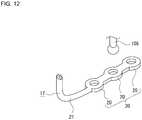
- the tension adjustment structure 30 is configured so as to include a plurality of attached portions 20, 20, ...
- the attached portions 20, 20 are included in the elastic member 17 and spaced apart from each other or disposed continuously in the longitudinal direction (see Fig. 12 ).
- any specific attached portion 20 is mounted on the mounting protrusion 106, which is disposed on the cargo deck 104 of the traveling structure 100.
- the stretch amount of the elastic member 17 is thereby varied and tension in the elastic member 17 can be adjusted.
- a tension adjustment structure 30A includes a plurality of protrusions 31, 31, ... and a plurality of protrusions 32, 32, ...
- the protrusions 31, 31, ... and the protrusions 32, 32, ... protrude outwardly from at least either one of the front surface panel portion 8 and the rear surface panel portion 9 of the outer casing 2.
- the protrusions 31, 31, ... are spaced apart vertically from each other and the protrusions 32, 32, ... are spaced apart vertically from each other (see Fig. 13 ).
- the protrusions 31, 31, ... and the protrusions 32, 32, ... are disposed to be spaced apart from each other in the crosswise direction.
- the protrusions 31, 31, ... are disposed at positions different from each other in the crosswise direction.
- the protrusions 32, 32, ... are also disposed at positions different from each other in the crosswise direction, as with the protrusions 31, 31, ...
- the attached portion 20 of a first elastic member 17 is attached on any specific protrusion 31 and the attached portion 20 of a second elastic member 17 is attached on any specific protrusion 32.
- the stretch amounts of the elastic members 17, 17 are thereby varied, so that tension in the elastic member 17 can be adjusted.
- the protrusions 31, 31, ... and the protrusions 32, 32, ... are disposed at positions different from each other in the crosswise direction. It is noted that, when the attached portions 20, 20 are mounted on any protrusions 31 and 32 other than the uppermost protrusions 31 and 32, the elastic member 17 does not interfere with the protrusions 31 and 32 disposed superior to the protrusions 31 and 32 on which the attached portions 20, 20 are mounted. This facilitates mounting of the elastic member 17 on the protrusions 31 and 32 and achieves a steady mounting condition of the elastic member 17 with respect to the protrusions 31 and 32.
- the tension adjustment structure 30A when the tension adjustment structure 30A is employed, the side on which the attached portion 20 is not mounted on the mounting protrusion 106 is mounted on the cargo deck 104 of the conveying apparatus 1 by any device other than the elastic member 17.
- a tension adjustment structure 30B has a plurality of mounting holes 33, 33, ... and a plurality of mounting holes 34, 34, ...
- the mounting holes 33, 33, ... and the mounting holes 34, 34, are formed in at least either one of the front surface panel portion 8 and the rear surface panel portion 9 of the outer casing 2.
- the mounting holes 33, 33, ... are spaced apart vertically from each other and the mounting holes 34, 34, ... are spaced apart vertically from each other.
- At least one end of each of the elastic members 17, 17 has a mounting bracket 35.
- the mounting bracket 35 is connected with the end of each of the elastic members 17, 17 and has a distal end bent (see Fig. 14 ).
- the mounting holes 33, 33, ... are spaced apart from the mounting holes 34, 34, ... in the crosswise direction.
- the mounting bracket 35 of a first one of the elastic members 17, 17 is inserted in any specific one of the mounting holes 33, 33, ... and the mounting bracket 35 of a second one of the elastic members 17, 17 is inserted in any specific one of the mounting holes 34, 34, ... Stretch amounts of the elastic members 17, 17 are thereby varied, so that tension in the elastic members 17, 17 can be adjusted.
- the tension adjustment structure 30B when the tension adjustment structure 30B is employed, the side on which the attached portion 20 is not mounted on the mounting protrusion 106 is mounted on the cargo deck 104 of the conveying apparatus 1 by any device other than the elastic member 17.
- a tension adjustment structure 30C is configured to include mounting members 36, 36 and locking portions 37, 37.
- the mounting members 36, 36 and the locking portions 37, 37 are disposed on at least either one of the front surface panel portion 8 and the rear surface panel portion 9 of the outer casing 2.
- the mounting members 36, 36 are spaced apart from each other in the crosswise direction.
- the locking portions 37, 37 are disposed close to the respective mounting members 36, 36 (see Figs. 15 and 16 ).
- the mounting member 36 is supported on the front surface panel portion 8 or the rear surface panel portion 9 so as to be pivotally rotatable about a left end or a right end thereof.
- the mounting member 36 includes a holding portion 36a at a center thereof.
- the holding portion 36a is formed into, for example, a curved surface protruding outwardly.
- the locking portion 37 is elastically deformable with respect to the front surface panel portion 8 or the rear surface panel portion 9.
- the locking portion 37 includes a lock tab 38 disposed at a distal end thereof.
- the lock tab 38 has a lock surface 38a and an inclined surface 38b.
- the lock surface 38a faces the front surface panel portion 8 or the rear surface panel portion 9.
- the inclined surface 38b joins the lock surface 38a.
- the mounting member 36 is rotated in a direction in which the mounting member 36 is closed from a condition in which the mounting member 36 is open with respect to the front surface panel portion 8 or the rear surface panel portion 9, the extended portion 21 of the elastic member 17 is pressed by the holding portion 36a from the outside, and a distal end portion 36b of the mounting member 36 is locked by the locking portion 37.
- the elastic member 17 is thereby held by the mounting member 36 and mounted on the outer casing 2.
- the mounting member 36 is locked in the locking portion 37 as follows. Specifically, the distal end portion 36b of the rotated mounting member 36 slides over the inclined surface 38b to thereby cause the locking portion 37 to be elastically deformed. Further rotating the mounting member 36 causes the distal end portion 36b to ride over the inclined surface 38b. Then, the locking portion 37 elastically restores to an original shape to thereby bring the lock surface 38a into locking engagement with an outer surface of the distal end portion 36b.
- the extended portion 21 is clamped between, and crushed by, the front surface panel portion 8 or the rear surface panel portion 9 and the holding portion 36a of the mounting member 36.
- the stretch amount of the elastic member 17 is varied depending on a position at which the extended portion 21 of the elastic member 17 is held by the holding portion 36a, so that tension in the elastic member 17 can be adjusted.
- the attached portion 20 may be mounted on the mounting protrusion 106 to thereby be mounted on the cargo deck 104 of the conveying apparatus 1.
- the foregoing has been described for a case in which the box-shaped outer casing 2 is open upwardly.
- an outer casing 2A having a skeleton structure may be employed (see Fig. 17 ).
- the outer casing 2A includes a plurality of columnar members 39, 39, ... and has a skeleton structure opening upwardly.
- the use of the outer casing 2A having the skeleton structure enables reduction in weight of the conveying apparatus 1.
- the use of the outer casing 2A allows vehicle traveling wind and natural wind to blow against the storage case 3 disposed inside through clearances in the columnar members 39, 39, ... This makes the configuration preferable for a case in which, for example, the stored article 50 stored in the storage case 3 needs cooling.
- skeleton structure may be employed for the storage case 3 in order, for example, to achieve reduction in weight.
- the bridging portions 22, 22 of the elastic members 17, 17 are disposed at positions immediately above both ends in the crosswise direction, respectively, of the storage case 3 (see Fig. 18 ).
- the disposition of the bridging portions 22, 22 at the positions immediately above both ends in the crosswise direction, respectively, of the storage case 3 under the condition in which the storage case 3 is suspended increases the distance between the elastic members 17, 17.
- the storage case 3 is thus held in a steady state and is hard to incline. A steady suspended state can thus be achieved for the storage case 3 by reducing inclination relative to the storage case 3.
- the elastic members 17, 17 are less likely to interfere with the stored article 50 that is placed in and removed from the storage space 3a, insertion and removal of the stored article 50 in and from the storage space 3a can be smoothly performed.
- the storage case 3 may be configured such that the front surface portion 14 and the rear surface portion 15 are supported by the front-side suspension devices 18, 18 and the rear-side suspension devices 19, 19, respectively, and the supported holes may be formed in the side surface portions 16, 16 and the side surface portions 16, 16 may then be supported by the front-side suspension devices 18, 18 and the rear-side suspension devices 19, 19, respectively.
- the bridging portions 22, 22 of the elastic members 17, 17 are disposed at positions outside both ends in the crosswise direction, respectively, of the storage case 3 (see Fig. 19 ).
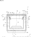
- the disposition of the bridging portions 22, 22 at the positions outside both ends in the crosswise direction, respectively, of the storage case 3 under the condition in which the storage case 3 is suspended causes tensile forces of the elastic members 17, 17 to be exerted on the storage case 3 in the crosswise direction. This prevents the storage case 3 from being deviated in the crosswise direction relative to the outer casing 2 and enables holding of the storage case 3 in a steady state.
- the conveying apparatus 1 may further include a lid member 40.
- the lid member 40 closes or opens an opening in the storage case 3 (see Fig. 20 ).
- the lid member 40 may be removable from the storage case 3 or supported by the storage case 3.
- the lid member 40 provided for opening or closing the opening in the storage case 3 improves a heat-retaining property when, for example, the stored article 50 stored in the storage space 3a is food and prevents entry of dust, dirt, and rainwater, for example, in the storage space 3a of the storage case 3.
- the front-side suspension device 18 and the rear-side suspension device 19 include the connecting portions 18a and 19a, respectively.
- an S-shaped hook including a continuous arcuate portion may, for example, be used.
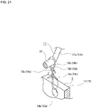
- a strap-shaped front-side suspension device 18A and a strap-shaped rear-side suspension device 19A may be used (see Fig. 21 ).
- the use of the strap-shaped front-side suspension device 18A and rear-side suspension device 19A allows a length and a size of connecting portions 18a and 19a, supported portions 18b and 19b, and supporting portions 18c and 19c to be varied depending on positions of knots.
- the position at which the storage case 3 is suspended relative to the outer casing 2 or 2A can be readily changed depending on, for example, weight of the stored article 50.
- the conveying apparatus 1 includes the stretchable elastic members 17, 17, which include bridging portions 22, 22 bridging the both ends in the fore-aft direction of the outer casing 2 and which are spaced apart from each other in the crosswise direction, and the front-side suspension devices 18, 18 and the rear-side suspension devices 19, 19, which are pivotally supported on the elastic members 17, 17 so as to be rockable about the supported portions 18b, 18b, and 19b, 19b.
- the storage case 3 is suspended on the elastic members 17, 17 by the front-side suspension devices 18, 18 and the rear-side suspension devices 19, 19 under a condition in which a gap is available between the storage case 3 and the outer casing 2.
- the storage case 3 is movable in the fore-aft direction relative to the outer casing 2 and is pivotally rockable about the supported portions 18b, 18b, and 19b, 19b.
- the storage case 3 is moved in a direction in which the storage case 3 is displaced in the vertical direction regardless of posture of the outer casing 4, so that a steady storage condition can be achieved for the stored article 50 during traveling of the traveling structure 100.
- the elastic members 17, 17 are disposed to be in parallel with each other, the distance between the elastic members 17, 17 remains constant at any position in the fore-aft direction.
- the storage case 3 is hard to incline with respect to the vertical direction and an even steadier storage condition can be achieved for the stored article 50 during traveling of the traveling structure 100.
Landscapes
- Engineering & Computer Science (AREA)
- Mechanical Engineering (AREA)
- Warehouses Or Storage Devices (AREA)
- Handcart (AREA)
- Vehicle Step Arrangements And Article Storage (AREA)
Abstract
Description
- The present invention relates to a conveying apparatus for conveying a stored article using a traveling structure.
- A known conveying apparatus is disposed in a traveling structure, such as a bicycle, a scooter, or an automobile, and conveys a stored article, such as food, stored thereinside through the traveling structure (see, for example,
Patent Literature 1,Patent Literature 2, and Patent Literature 3). - Such a conveying apparatus is used in, for example, home delivery to an orderer from a store that has received the order or a distribution center and is disposed on a cargo deck of, for example, a bicycle or a scooter.
-
- Patent Literature 1:
JP 2014-184748 A - Patent Literature 2:
JP 2012-116326 A - Patent Literature 3:
JP 2008-230292 A - With the conveying apparatus used in, for example, home delivery, the stored article, because of being conveyed by the traveling structure, is subjected to external force due to, for example, vibration and acceleration and deceleration, while the traveling structure is traveling. The external force to be applied to the stored article tends to be large particularly during traveling along a slope, in addition to sudden acceleration and sudden deceleration.
- The stored article is moved or swayed inside the conveying apparatus when an external force is applied to the stored article during traveling. If the stored article is moved or swayed excessively and if the stored article is food in particular, the food may spill from a container thereof or an arrangement thereof may change.
- It is therefore an object of a conveying apparatus according to the present invention to deal with problems as described above and achieve a steady storage condition for a stored article during traveling of a traveling structure.
- First, a conveying apparatus according to the present invention includes: an outer casing for disposing the conveying apparatus on a traveling structure; a storage case that is disposed inside the outer casing and that allows a stored article to be placed therein and removed therefrom from above; a plurality of stretchable elastic members that are spaced apart from each other in a crosswise direction and each of which includes a bridging portion that bridges between front and rear ends of the outer casing in a traveling direction of the traveling structure; and a plurality of suspension devices that are spaced apart from each other at least in a fore-aft direction and each of which includes an upper end assuming a supported portion that is supported slidably on the elastic member and a lower end assuming a supporting portion that supports the storage case. In the conveying apparatus, the suspension devices are supported by the elastic members pivotally rockably about the supported portions, the storage case is supported by the suspension devices pivotally rockably about the supporting portions, and the storage case is suspended on the elastic members by the suspension devices under a condition in which a gap is available between the storage case and the outer casing.
- The configuration allows the storage case to be moved in the fore-aft direction relative to the outer casing and to be rocked about the supported portions during traveling of the traveling structure.
- Second, in the conveying apparatus described above, preferably, the elastic members are disposed in parallel with each other.
- The configuration results in a distance between the elastic members remaining constant at any position in the fore-aft direction. Thus, the storage case is hard to incline with respect to the vertical direction.
- Third, in the conveying apparatus described above, preferably, the elastic members include two elastic members, and the bridging portions of the two elastic members are disposed at positions immediately above both ends in the crosswise direction, respectively, of the storage case.
- The configuration provides a greater distance between the elastic members, so that the storage case is held in a steady state in the crosswise direction.
- Fourth, in the conveying apparatus described above, preferably, the suspension devices each include a connecting portion that connects between the supported portion and the supporting portion and the connecting portions are disposed between the storage case and the outer casing.
- The configuration reduces a space taken up by the suspension devices inside the storage case.
- Fifth, in the conveying apparatus described above, preferably, the conveying apparatus further includes a tension adjustment structure that adjusts tension in the elastic members.
- The configuration enables the position at which the storage case is suspended with respect to the outer casing and a stretch state of the elastic members during traveling of the traveling structure to be varied through adjustment of the tension in the elastic members.
- Sixth, in the conveying apparatus described above, preferably, each of both ends of each of the elastic members in a direction in which the elastic member is stretched assumes an attached portion to be attached on the traveling structure.
- The configuration allows the both ends of each of the elastic members to be attached to the traveling structure to thereby enable the bridging portions to bridge between front and rear ends of the outer casing.
- In accordance with the aspect of the present invention, while the traveling structure is traveling, the storage case is movable in the fore-aft direction relative to the outer casing and is pivotally rockable about the supported portions. Thus, the storage case is moved in a direction in which the storage case is displaced in the vertical direction regardless of posture of the outer casing, so that a steady storage condition can be achieved for the stored article during traveling of the traveling structure.
-
-
Fig. 1 is a side elevation view of a conveying apparatus disposed on a traveling structure, depicting, as withFigs. 2 to 21 , the conveying apparatus according to an embodiment of the present invention. -
Fig. 2 is a perspective view of the conveying apparatus. -
Fig. 3 is an enlarged perspective view of a part of the conveying apparatus. -
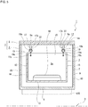
Fig. 4 is a cross-sectional view of the conveying apparatus as viewed from a crosswise direction. -
Fig. 5 is a cross-sectional view of the conveying apparatus as viewed from a fore-aft direction. -
Fig. 6 is a cross-sectional view of the conveying apparatus when a traveling structure is accelerated. -
Fig. 7 is a cross-sectional view of the conveying apparatus when the traveling structure is decelerated. -
Fig. 8 is a cross-sectional view of the conveying apparatus when the traveling structure travels along an uphill. -
Fig. 9 is a cross-sectional view of the conveying apparatus when a suspension device does not slide relative to an elastic member while the traveling structure is traveling along an uphill. -
Fig. 10 is a cross-sectional view of the conveying apparatus when the traveling structure travels along a downhill. -
Fig. 11 is a cross-sectional view of the conveying apparatus as viewed from a rear when the traveling structure is inclined in the crosswise direction. -
Fig. 12 depicts, as withFigs. 13 to 16 , an example of a tension adjustment structure,Fig. 12 being a perspective view of one example of the tension adjustment structure. -
Fig. 13 is a perspective view of another example of the tension adjustment structure. -
Fig. 14 is a perspective view of still another example of the tension adjustment structure. -
Fig. 15 depicts, as withFig. 16 , a further example of the tension adjustment structure,Fig. 15 being a perspective view of the example of the tension adjustment structure. -
Fig. 16 is a plan view including a partial cross-sectional view of a condition in which the elastic member is held by the tension adjustment structure. -
Fig. 17 is a perspective view of another configuration example of an outer casing. -
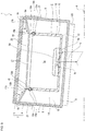
Fig. 18 is a plan view depicting a condition in which bridging portions of the elastic members are disposed at positions immediately above both ends in the crosswise direction of a suspended storage case. -
Fig. 19 is a cross-sectional view depicting a condition in which the bridging portions of the elastic members are disposed at positions outside both ends in the crosswise direction of a suspended storage case. -
Fig. 20 is a perspective view of an example of a configuration including a lid member that opens or closes an opening in the storage case. -
Fig. 21 is a perspective view of an example of a configuration in which the storage case is suspended by strap-shaped members. - The following describes, with reference to the accompanying drawings, modes for carrying out a conveying apparatus according to the present invention.
- The following describes an example in which the conveying apparatus is disposed on a cargo deck of a bicycle as a traveling structure. The conveying apparatus may nonetheless be disposed on, for example, a cargo deck of another traveling structure of a two-wheeled, three-wheeled, or four-wheeled motorcycle or automobile, and the like.
- A general configuration of a traveling structure (bicycle) will first be described (see
Fig. 1 ). - This
traveling structure 100 includes avehicle body 101, afront wheel 102, and arear wheel 103. Thevehicle body 101 includes a handlebar and a saddle, and the like. Thefront wheel 102 and therear wheel 103 are supported by thevehicle body 101. Acargo deck 104, which is coupled with thevehicle body 101, is disposed superior to therear wheel 103. - The
cargo deck 104 includes a mountingstand 105 and mountingprotrusions stand 105 is positioned in a horizontal state. The mountingprotrusions stand 105. The mountingprotrusions protrusions - A configuration of a conveying apparatus will be described below (see, for example,
Figs. 2 to 5 ). - This conveying
apparatus 1 includes anouter casing 2 and astorage case 3. - The
outer casing 2 includes, for example, a box-shapedcase portion 4 and acover portion 5. Thecase portion 4 is open upwardly. Thecover portion 5 opens and closes anopening 4a in thecase portion 4. Theouter casing 2 assumes a structure for disposing the conveyingapparatus 1 on thecargo deck 104. - The
case portion 4 includes a bottomsurface panel portion 6 and an outerperipheral panel portion 7. The bottomsurface panel portion 6 is placed on the mountingstand 105 of the travelingstructure 100. The outerperipheral panel portion 7 protrudes upwardly from an outer peripheral portion of the bottomsurface panel portion 6. The outerperipheral panel portion 7 is composed of a frontsurface panel portion 8, a rearsurface panel portion 9, and a pair of sidesurface panel portions surface panel portion 8 and the rearsurface panel portion 9 are disposed to be spaced apart in the fore-aft direction. The sidesurface panel portions - The front
surface panel portion 8 and the rearsurface panel portion 9 have lockingrecesses - The
cover portion 5 is coupled with an upper end portion of one of the sidesurface panel portions cover portion 5 is pivotally rotated about thehinges opening 4a in thecase portion 4. - It is noted that the
cover portion 5 may not have to be coupled with thecase portion 4. Thecover portion 5 may, for example, be configured so as to be removed from thecase portion 4 under a condition in which theopening 4a in thecase portion 4 is not closed. - The
storage case 3 is formed, for example, into a box shape opening upwardly and has an outline shape smaller than theouter casing 2. Thestorage case 3 is disposed under a condition in which thestorage case 3 is suspended inside theouter casing 2. - The
storage case 3 includes abottom surface portion 12 and an outerperipheral surface portion 13. Thebottom surface portion 12 has a plate shape facing in a vertical direction. The outerperipheral surface portion 13 protrudes upwardly from an outer peripheral portion of thebottom surface portion 12. The outerperipheral surface portion 13 is composed of afront surface portion 14 and arear surface portion 15, and a pair ofside surface portions front surface portion 14 and therear surface portion 15 are disposed to be spaced apart in the fore-aft direction. Theside surface portions - The
front surface portion 14 and therear surface portion 15 have supportedholes holes holes holes - The
storage case 3 has an internal space defined as astorage space 3a. A storedarticle 50, such as food, is stored in thestorage space 3a. - The
storage case 3 is suspended onelastic members side suspension devices side suspension devices - The
elastic members portions elastic members extended portions portion 22. Out of a portion extending between the attachedportions extended portions portions extended portions portion 22. - Each of the
elastic members portions - Each of the front-
side suspension devices portion 18a, an arcuate (hook-shaped) supportedportion 18b, and an arcuate (hook-shaped) supportingportion 18c. The supportedportion 18b joins an upper end of the connectingportion 18a. The supportingportion 18c joins a lower end of the connectingportion 18a. The supportedportion 18b has an axis orthogonal to an axis of the supportingportion 18c. - Each of the rear-
side suspension devices portion 19a, an arcuate (hook-shaped) supportedportion 19b, and an arcuate (hook-shaped) supportingportion 19c. The supportedportion 19b joins an upper end of the connectingportion 19a. The supportingportion 19c joins a lower end of the connectingportion 19a. The supportedportion 19b has an axis orthogonal to an axis of the supportingportion 19c. - Under a condition in which the bottom
surface panel portion 6 of theouter casing 2 is placed on the mountingstand 105 of thecargo deck 104, the attachedportions protrusions elastic members cover portion 5 of theouter casing 2 is open and theelastic members outer casing 2 by having portions thereof bridging between the frontsurface panel portion 8 and the rearsurface panel portion 9. The portion of theelastic member 17 bridging between the frontsurface panel portion 8 and the rearsurface panel portion 9 functions as the bridgingportion 22 and the portion of theelastic member 17 between the bridgingportion 22 and the attachedportion extended portion - Both ends of the bridging
portion 22 of theelastic member 17 are inserted in the locking recesses 8a and 9a in the frontsurface panel portion 8 and the rearsurface panel portion 9, respectively. The insertion of the both ends of the bridgingportion 22 of theelastic member 17 in the locking recesses 8a and 9a in the frontsurface panel portion 8 and the rearsurface panel portion 9, respectively, causes theelastic member 17 to be positioned correctly in the crosswise direction relative to theouter casing 2, so that theelastic member 17 is restricted from being displaced in the crosswise direction. - The
elastic members outer casing 2, are placed in a condition in which theelastic members elastic members outer casing 2 by being stretched to be elastically deformed. The mounting of theelastic members outer casing 2 causes theelastic members case portion 4 of theouter casing 2. As a result, the bottomsurface panel portion 6 is pressed up against the mountingstand 105 from above, so that a steady mounting condition can be achieved with respect to thecargo deck 104 of the conveyingapparatus 1. - Thus, the conveying
apparatus 1 is mounted on thecargo deck 104 by theelastic members elastic members apparatus 1 on thecargo deck 104, in addition to a function of suspending thestorage case 3, so that functionality of theelastic members elastic members storage case 3 and the function of mounting the conveyingapparatus 1 on thecargo deck 104 eliminates the need for additional member or work allocated to the mounting of the conveyingapparatus 1 on thecargo deck 104. Thus, the mounting of the conveyingapparatus 1 can be easily performed through simple steps without involving an increased number of parts used. - The supported
portion 18b of the front-side suspension device 18 and the supportedportion 19b of the rear-side suspension device 19 are assembled with theelastic member 17. - The supporting
portions side suspension devices portions side suspension devices holes holes storage case 3, which is disposed inside theouter casing 2. Thus, thestorage case 3 is suspended on theelastic members outer casing 2, by the front-side suspension devices side suspension devices - At this time, preferably, the supporting
portion 18c of the front-side suspension device 18 and the supportingportion 19c of the rear-side suspension device 19 are inserted in the supportedhole 14a and the supportedhole 15a, respectively, from a front surface side of thefront surface portion 14 and a rear surface side of therear surface portion 15, respectively. - The insertion of the supporting
portions holes front surface portion 14 and the rear surface side of therear surface portion 15 causes the connectingportions peripheral surface portion 13 of thestorage case 3 and the outerperipheral panel portion 7 of theouter casing 2. The foregoing configuration results in a reduced space taken up by the front-side suspension device 18 and the rear-side suspension device 19 in thestorage space 3a of thestorage case 3, compared with a configuration in which the supportingportions holes front surface portion 14 and a front surface side of therear surface portion 15. - Thus, because the connecting
portions storage case 3 and theouter casing 2, the front-side suspension device 18 and the rear-side suspension device 19 do not serve as a hindrance for the storedarticle 50 to be placed in, and removed from, thestorage case 3. Thus, placement of the storedarticle 50 in, and removal of the storedarticle 50 from, thestorage space 3a of thestorage case 3 can be performed easily. - The insertion of the supporting
portions holes front surface portion 14 and the rear surface side of therear surface portion 15 provides a greater distance between the front-side suspension device 18 and the rear-side suspension device 19, compared with the insertion of the supportingportions holes front surface portion 14 and the front surface side of therear surface portion 15. Thus, thestorage case 3 can be suspended in a steady state on theelastic members side suspension devices side suspension devices - The
storage case 3 is suspended under a condition in which a gap exists between an outer surface of the outerperipheral surface portion 13 and an inner surface of the outerperipheral panel portion 7 of theouter casing 2, and a gap exists between a bottom surface of thebottom surface portion 12 and an upper surface of the bottomsurface panel portion 6 of theouter casing 2. At this time, in theelastic member 17, the bridgingportion 22 bridges between the frontsurface panel portion 8 and the rearsurface panel portion 9 of theouter casing 2 and theextended portions surface panel portion 8 and the rear surface of the rearsurface panel portion 9, respectively. - Under a condition in which the
storage case 3 is suspended, the supportedportions side suspension devices portions side suspension devices elastic members portions portions elastic members storage case 3 is movable with respect to theouter casing 2 in the fore-aft direction. - Under a condition in which the
storage case 3 is suspended on theelastic members side suspension devices side suspension devices side suspension devices side suspension devices storage case 3 causes theelastic members portions side suspension devices portions side suspension devices outer casing 2. At this time, portions in theelastic members portions surface panel portion 8 and portions in theelastic members portions surface panel portion 9 are each inclined such that an end on the side of thestorage case 3 is displaced downwardly. The portions inclined in theelastic members inclined portions portions - The front-side
inclined portion 17a and the rear-sideinclined portion 17b are stretched within a range of elastic deformation by weight of, for example, thestorage case 3. The front-sideinclined portion 17a is set to have a stretch amount identical to a stretch amount set for the rear-sideinclined portion 17b under a reference state in which a center of thestorage case 3 in the fore-aft direction is aligned with a center between the frontsurface panel portion 8 and the rearsurface panel portion 9 of theouter casing 2. The stretch amount of the front-sideinclined portion 17a and the rear-sideinclined portion 17b is further set to be variable depending on a position to which the front-side suspension device 18 and the rear-side suspension device 19 are moved in the fore-aft direction such that, when the front-side suspension device 18 and the rear-side suspension device 19 are moved in the fore-aft direction relative to the reference state as a result of thestorage case 3 having slid relative to theelastic member 17. - When, for example, the
storage case 3 is moved toward the rear from the reference state, the front-sideinclined portion 17a has a length longer than a length of the rear-sideinclined portion 17b. Then, the stretch amount of the front-sideinclined portion 17a increases, while the stretch amount of the rear-sideinclined portion 17b decreases, so that the front-sideinclined portion 17a has a stretch amount greater than the stretch amount of the rear-sideinclined portion 17b. In contrast, when thestorage case 3 is moved toward the front from the reference state, the rear-sideinclined portion 17b has a length longer than a length of the front-sideinclined portion 17a. Then, the stretch amount of the rear-sideinclined portion 17b increases, while the stretch amount of the front-sideinclined portion 17a decreases, so that the rear-sideinclined portion 17b has a stretch amount greater than the stretch amount of the front-sideinclined portion 17a. - When the
elastic members surface panel portion 8 and the rearsurface panel portion 9 under a condition in which thestorage case 3 is suspended as described above, the weight of the front-side suspension devices side suspension devices storage case 3 causes theelastic members elastic members case portion 4 of theouter casing 2. As a result, the bottomsurface panel portion 6 is further pressed up against the mountingstand 105 from above, so that an even steadier mounting condition can be achieved with respect to thecargo deck 104 of the conveyingapparatus 1. - The front-
side suspension devices side suspension devices portions portions elastic members - Under the condition in which the
storage case 3 is suspended as described above, opening thecover portion 5 enables the storedarticle 50 to be placed in, and removed from, thestorage space 3a of thestorage case 3. - It is noted that, when the
storage case 3 is suspended, theelastic members cover portion 5 does not interfere with theelastic members cover portion 5 is closed relative to thecase portion 4. Thecover portion 5 can thus be brought into tight contact with thecase portion 4 and a favorable closure state can be achieved of theouter casing 2. - The portions of the
elastic members surface panel portion 8 and the rearsurface panel portion 9 by appropriate fixing devices. It is noted that the conveyingapparatus 1 may even be configured so as not to have the locking recesses 8a, 8a, 9a, 9a in the frontsurface panel portion 8 and the rearsurface panel portion 9. In this case, thecover portion 5 is closed relative to thecase portion 4, under which condition thecover portion 5 presses theelastic members surface panel portion 8 and the rearsurface panel portion 9, thereby theelastic members storage case 3. - When the
elastic members surface panel portion 8 and the rearsurface panel portion 9 under a condition in which the storedarticle 50 is stored in thestorage space 3a of thestorage case 3, the weight of the storedarticle 50 further stretches theelastic members elastic members case portion 4 of theouter casing 2. As a result, the bottomsurface panel portion 6 is further pressed up against the mountingstand 105 from above, so that an even steadier mounting condition can be achieved with respect to thecargo deck 104 of the conveyingapparatus 1. - It is noted that the
elastic members portion 22, which bridges between the frontsurface panel portion 8 and the rearsurface panel portion 9 of theouter casing 2, and may each be configured so as not to include the attachedportions extended portions elastic members surface panel portion 8 and the upper surface of the rearsurface panel portion 9 by appropriate fixing devices. Additionally, mounting on thecargo deck 104 of the conveyingapparatus 1 is performed by any device other than theelastic members - It is, however, noted that the attached
portions elastic member 17 as described above enable the both ends of theelastic member 17 to be attached to the mountingprotrusions structure 100, to thereby allow the bridgingportion 22 to bridge between the front and rear ends of theouter casing 2. Workability can thus be enhanced in mounting theelastic member 17 on theouter casing 2. - Additionally, no need exists to use additional device for mounting on the
cargo deck 104 of the conveyingapparatus 1 in addition to theelastic member 17 and mounting of the conveyingapparatus 1 on the travelingstructure 100 can be performed simultaneously with the mounting of theelastic member 17 on theouter casing 2. Thus, workability can be enhanced, while reduction in the number of parts used is achieved. - The following describes operation of the conveying
apparatus 1 when the storedarticle 50 is conveyed by the traveling structure 100 (seeFigs. 4 to 11 ). It is noted thatFigs. 4 to 11 each indicate an imaginary horizontal plane H for easier understanding of inclined conditions of theouter casing 2 and thestorage case 3. - The following first describes operation of the conveying
apparatus 1 when the travelingstructure 100 travels along a level road surface that is not inclined. - When the bottom
surface panel portion 6 of theouter casing 2 is level under a condition before the travelingstructure 100 travels, the suspendedstorage case 3 is placed in the reference state in which the lower surface of thebottom surface portion 12 faces in the vertical direction (gravitational direction) and extends in parallel with the bottom surface panel portion 6 (seeFigs. 4 and5 ). In the following, a condition of thestorage case 3 in which the lower surface of thebottom surface portion 12 faces in the vertical direction will be referred to as an "equilibrium state." - When the traveling
structure 100 is started and accelerated, the conveyingapparatus 1 mounted on thecargo deck 104 advances as the travelingstructure 100 advances. A force is, however, exerted by inertia on the front-side suspension device 18 and the rear-side suspension device 19, which are slidably supported by theelastic member 17, to move the front-side suspension device 18 and the rear-side suspension device 19 toward the rear with respect to theelastic member 17. The inertia also exerts a force on the suspendedstorage case 3 to move thestorage case 3 toward the rear relative to theouter casing 2. - While the force is exerted on the front-
side suspension device 18 and the rear-side suspension device 19 to relatively move toward the rear as described above, the rear-sideinclined portion 17b, which is included in theelastic member 17 and which is inclined downwardly toward the front, restricts the rear-side suspension device 19 from moving toward the rear. Additionally, a friction force is generated between each of the front-side suspension device 18 and the rear-side suspension device 19 and theelastic member 17. - Thus, the rearward movement of the rear-
side suspension device 19 is limited by the friction force and the restriction force of the rear-sideinclined portion 17b. When the travelingstructure 100 is accelerated, the front-side suspension device 18 and the rear-side suspension device 19 move toward the rear only a small amount or may not move at all toward the rear. - The amount of movement of the rear-
side suspension device 19 toward the rear is limited by the friction force and the restriction force of the rear-sideinclined portion 17b as described above. Even when the front-side suspension device 18 and the rear-side suspension device 19 are not moved toward the rear relative to theelastic member 17, however, because of the front-side suspension device 18 and the rear-side suspension device 19 being rockably supported by theelastic member 17, the supportingportion 18c of the front-side suspension device 18 and the supportingportion 19c of the rear-side suspension device 19 are pivotally rocked and moved toward the rear about the supportedportion 18b and the supportedportion 19b, respectively (seeFig. 6 ). - The
storage case 3, on which a force to move toward the rear relative to theouter casing 2 is being exerted by inertia at this time, is pivotally rockable about the supportingportion 18c of the front-side suspension device 18 and the supportingportion 19c of the rear-side suspension device 19. Thus, thestorage case 3, while being moved toward the rear relative to theouter casing 2, is pivotally rocked about the supportingportions storage case 3 is not inclined in response to the movement of the front-side suspension device 18 and the rear-side suspension device 19, but maintains the equilibrium state. - As such, the
storage case 3 maintains the equilibrium state even while the travelingstructure 100 is being accelerated, so that the storedarticle 50 stored inside thestorage case 3 is not inclined inside thestorage case 3 and a favorable storage state of the storedarticle 50 can be achieved. - When the front-
side suspension device 18 and the rear-side suspension device 19 are moved toward the rear relative to theelastic member 17 as the travelingstructure 100 is accelerated, the length of the front-sideinclined portion 17a becomes longer than the length of the rear-sideinclined portion 17b and thestorage case 3 is inclined downwardly toward the front. The amount of movement toward the rear of the front-side suspension device 18 and the rear-side suspension device 19 is, however, small as described above. Thus, an angle of inclination of thestorage case 3 is small and an angle of inclination of the storedarticle 50 is small, too, when the front-side suspension device 18 and the rear-side suspension device 19 are moved toward the rear relative to theelastic member 17. A favorable storage state of the storedarticle 50 can thus be achieved in this case, too. - When the traveling
structure 100 is decelerated from a traveling state, a force is exerted by inertia on the front-side suspension device 18 and the rear-side suspension device 19, which are slidably supported by theelastic member 17, to move the front-side suspension device 18 and the rear-side suspension device 19 toward the front relative to theelastic member 17. The inertia also exerts a force on the suspendedstorage case 3 to move thestorage case 3 forward relative to theouter casing 2. - A force is exerted on the front-
side suspension device 18 and the rear-side suspension device 19 to move the front-side suspension device 18 and the rear-side suspension device 19 relatively toward the front as such. Because of the front-sideinclined portion 17a, which is inclined downwardly toward the rear, included in theelastic member 17, however, the front-side suspension device 18 is restricted from moving toward the front by the front-sideinclined portion 17a. Additionally, a friction force is generated between each of the front-side suspension device 18 and the front-side suspension device 18 and theelastic member 17. - Thus, the forward movement of the front-
side suspension device 18 is limited by the friction force and the restriction force of the front-sideinclined portion 17a. When the travelingstructure 100 is decelerated, the front-side suspension device 18 and the rear-side suspension device 19 move toward the front only a small amount or may not move at all toward the front. - The amount of movement of the front-
side suspension device 18 toward the front is limited by the friction force and the restriction force of the front-sideinclined portion 17a as described above. Even when the front-side suspension device 18 and the rear-side suspension device 19 are not moved toward the front relative to theelastic member 17, however, because of the front-side suspension device 18 and the rear-side suspension device 19 being rockably supported by theelastic member 17, the supportingportion 18c of the front-side suspension device 18 and the supportingportion 19c of the rear-side suspension device 19 are pivotally rocked and moved toward the front about the supportedportion 18b and the supportedportion 19b, respectively (seeFig. 7 ). - The
storage case 3, on which a force to move thestorage case 3 toward the front relative to theouter casing 2 is being exerted by inertia at this time, is pivotally rockable about the supportingportion 18c of the front-side suspension device 18 and the supportingportion 19c of the rear-side suspension device 19. Thus, thestorage case 3, while being moved toward the front relative to theouter casing 2, is pivotally rocked about the supportingportions storage case 3 is not inclined in response to the movement of the front-side suspension device 18 and the rear-side suspension device 19, but maintains the equilibrium state. - As such, the
storage case 3 maintains the equilibrium state even while the travelingstructure 100 is being decelerated, so that the storedarticle 50 stored inside thestorage case 3 is not inclined inside thestorage case 3 and a favorable storage state of the storedarticle 50 can be achieved. - When the front-
side suspension device 18 and the rear-side suspension device 19 are moved toward the front relative to theelastic member 17 as the travelingstructure 100 is decelerated, the length of the rear-sideinclined portion 17b becomes longer than the length of the front-sideinclined portion 17a and thestorage case 3 is inclined downwardly toward the rear. The amount of movement toward the front of the front-side suspension device 18 and the rear-side suspension device 19 is, however, small as described above. Thus, the angle of inclination of thestorage case 3 is small and the angle of inclination of the storedarticle 50 is small, too, when the front-side suspension device 18 and the rear-side suspension device 19 are moved toward the front relative to theelastic member 17. A favorable storage state of the storedarticle 50 can thus be achieved in this case, too. - The following describes operation of the conveying
apparatus 1 when the travelingstructure 100 travels along an inclined road surface. - Under a condition in which the traveling
structure 100 travels along an uphill road, theouter casing 2 and theelastic members Fig. 8 ). - Thus, a force is exerted, by tare and weight of the
storage case 3 and of the storedarticle 50, on the front-side suspension device 18 and the rear-side suspension device 19, which are slidably supported by theelastic member 17, to move the front-side suspension device 18 and the rear-side suspension device 19 toward the rear relative to theelastic member 17. A force is also exerted, by tare and weight of the storedarticle 50, on the suspendedstorage case 3 to move thestorage case 3 toward the rear relative to theouter casing 2. At this time, a force is exerted in the vertical direction by gravity on the front-side suspension device 18, the rear-side suspension device 19, and thestorage case 3. - Because the force is exerted on the front-
side suspension device 18, the rear-side suspension device 19, and thestorage case 3 to move the front-side suspension device 18, the rear-side suspension device 19, and thestorage case 3 relatively toward the rear as described above, the front-side suspension device 18 and the rear-side suspension device 19 are slid by theelastic member 17 to move toward the rear and thestorage case 3 is moved toward the rear in response to the movement of the front-side suspension device 18 and the rear-side suspension device 19. Because of the rear-sideinclined portion 17b, which is inclined downwardly toward the front and which is included in theelastic member 17, and because of the friction force generated between each of the front-side suspension device 18 and the rear-side suspension device 19 and theelastic member 17, however, the front-side suspension device 18, the rear-side suspension device 19, and thestorage case 3 are moved toward the rear relative to theelastic member 17 and theouter casing 2 over a predetermined range that corresponds to the angle of inclination of the road surface. - Because the front-
side suspension device 18 and the rear-side suspension device 19 are moved toward the rear relative to theelastic member 17 at this time, the length of the front-sideinclined portion 17a becomes long and the length of the rear-sideinclined portion 17b becomes short. Additionally, because of the force exerted in the vertical direction by gravity on thestorage case 3, a force is exerted on thestorage case 3 in a direction to incline thestorage case 3 downwardly toward the front relative to theouter casing 2. Thus, the weight of thestorage case 3 and the storedarticle 50 causes the stretch amount of the front-sideinclined portion 17a to increase and the stretch amount of the rear-sideinclined portion 17b to decrease, so that thestorage case 3 is not inclined and maintains the equilibrium state. - Because the
storage case 3 maintains the equilibrium state even when the travelingstructure 100 travels along an uphill road, the storedarticle 50 stored in thestorage case 3 is not inclined inside thestorage case 3 and a favorable storage state of the storedarticle 50 can be achieved. - It is noted that the front-
side suspension device 18 and the rear-side suspension device 19 may not be moved toward the rear because the movement of the front-side suspension device 18 and the rear-side suspension device 19 toward the rear is restricted by the friction force between each of the front-side suspension device 18 and the rear-side suspension device 19 and theelastic member 17 or the restriction force of the rear-sideinclined portion 17b under the condition in which the travelingstructure 100 travels along the uphill road (seeFig. 9 ). - A force in a vertical direction V is exerted by gravity on the
storage case 3 even under the above case. At this time, the front-side suspension device 18 is stretched in a direction, which extends obliquely downwardly toward the rear, the front-side suspension device 18 is stretched in a direction P, which extends obliquely downwardly toward the rear and the rear-side suspension device 19 is stretched in a direction Q, which extends obliquely downwardly toward the front. - With the force exerted at this time on the
storage case 3 in the vertical direction V, a component Vp acting in the direction in which the front-side suspension device 18 is stretched is set to be greater than a component Vq acting in the direction in which the rear-side suspension device 19 is stretched. Thus, the front-side suspension device 18 is stretched by the component Vp more than the rear-side suspension device 19, so that thestorage case 3 is inclined downwardly toward the front to a position close to the equilibrium state. - Thus, the
storage case 3 is not likely to be inclined greatly relative to the equilibrium state and maintains a state close to the equilibrium state. - As such, the
storage case 3 maintains a state close to the equilibrium state even when the front-side suspension device 18 and the rear-side suspension device 19 are not moved toward the rear as the travelingstructure 100 travels along an uphill road. Thus, the storedarticle 50 stored in thestorage case 3 is not inclined greatly inside thestorage case 3, so that a favorable storage state of the storedarticle 50 is achieved. - Under a condition in which the traveling
structure 100 travels along a downhill, theouter casing 2 and theelastic members Fig. 10 ). - Thus, a force is exerted, by tare and weight of the
storage case 3 and of the storedarticle 50, on the front-side suspension device 18 and the rear-side suspension device 19, which are slidably supported by theelastic member 17, to move the front-side suspension device 18 and the rear-side suspension device 19 toward the front relative to theelastic member 17. A force is also exerted, by tare and weight of the storedarticle 50, on the suspendedstorage case 3 to move thestorage case 3 toward the front relative to theouter casing 2. At this time, a force is exerted in the vertical direction by gravity on the front-side suspension device 18, the rear-side suspension device 19, and thestorage case 3. - Because the force is exerted on the front-
side suspension device 18, the rear-side suspension device 19, and thestorage case 3 to move the front-side suspension device 18, the rear-side suspension device 19, and thestorage case 3 relatively toward the front as described above, the front-side suspension device 18 and the rear-side suspension device 19 are slid by theelastic member 17 to move toward the front and thestorage case 3 is moved toward the front in response to the movement of the front-side suspension device 18 and the rear-side suspension device 19. Because of the front-sideinclined portion 17a, which is inclined downwardly toward the rear and which is included in theelastic member 17, and because of the friction force generated between each of the front-side suspension device 18 and the rear-side suspension device 19 and theelastic member 17, however, the front-side suspension device 18, the rear-side suspension device 19, and thestorage case 3 are performed relative to theelastic member 17 and theouter casing 2 over a predetermined range that corresponds to the angle of inclination of the road surface. - Because the front-
side suspension device 18 and the rear-side suspension device 19 are moved toward the front relative to theelastic member 17 at this time, the length of the rear-sideinclined portion 17b becomes long and the length of the front-sideinclined portion 17a becomes short. Additionally, because of the force exerted in the vertical direction by gravity on thestorage case 3, a force is exerted on thestorage case 3 in a direction to incline thestorage case 3 downwardly toward the rear relative to theouter casing 2. Thus, the weight of thestorage case 3 and the storedarticle 50 causes the stretch amount of the rear-sideinclined portion 17b to increase and the stretch amount of the front-sideinclined portion 17a to decrease, so that thestorage case 3 is not inclined and maintains the equilibrium state. - Because the
storage case 3 maintains the equilibrium state even when the travelingstructure 100 travels along a downhill road, the storedarticle 50 stored in thestorage case 3 is not inclined inside thestorage case 3 and a favorable storage state of the storedarticle 50 can be achieved. - It is noted that the front-
side suspension device 18 and the rear-side suspension device 19 may not be moved toward the front because the movement of the front-side suspension device 18 and the rear-side suspension device 19 toward the front is restricted by the friction force between each of the front-side suspension device 18 and the rear-side suspension device 19 and theelastic member 17 or the restriction force of the front-sideinclined portion 17a under the condition in which the travelingstructure 100 travels along the downhill road. - A force in the vertical direction is exerted by gravity on the
storage case 3 in this case, too. In contrast to the case in which the front-side suspension device 18 and the rear-side suspension device 19 are not moved toward the rear when the travelingstructure 100 travels along the uphill road, the component acting in the direction in which the rear-side suspension device 19 is stretched is set to be greater than the component acting in the direction in which the front-side suspension device 18 is stretched. Thus, the rear-side suspension device 19 is stretched more than the front-side suspension device 18 by the component of force exerted on thestorage case 3 in the vertical direction, so that thestorage case 3 is inclined downwardly toward the rear to a position close to the equilibrium state. - Thus, the
storage case 3 is not likely to be inclined greatly relative to the equilibrium state and maintains a state close to the equilibrium state. - As such, the
storage case 3 maintains a state close to the equilibrium state even when the front-side suspension device 18 and the rear-side suspension device 19 are not moved toward the front as the travelingstructure 100 travels along a downhill road. Thus, the storedarticle 50 stored in thestorage case 3 is not inclined greatly inside thestorage case 3, so that a favorable storage state of the storedarticle 50 is achieved. - It is noted that the traveling
structure 100 may be decelerated or accelerated while traveling along an uphill or downhill road. In such a case, the operation during deceleration or the operation during acceleration described above is performed under a condition in which thestorage case 3 maintains the equilibrium state on the uphill or downhill road, to thereby ensure that thestorage case 3 maintains the equilibrium state or a state close to the equilibrium state. Thus, the description of the operation of the conveyingapparatus 1 when the travelingstructure 100 is decelerated or accelerated while traveling along an uphill or downhill road is omitted. - The following describes operation of the conveying
apparatus 1 when the travelingstructure 100 inclines in the crosswise direction while, for example, making a right turn or a left turn. The operation of the conveyingapparatus 1 is reversed between a leftward inclination and a rightward inclination. Thus, the following illustrates as an example the operation when the travelingstructure 100 inclines to the right relative to a traveling direction (seeFig. 11 ). - When the traveling
structure 100 inclines to the right, theouter casing 2 and theelastic members - Thus, a force is exerted on the front-
side suspension device 18 and the rear-side suspension device 19, which are rockably supported by theelastic member 17, to rock the front-side suspension device 18 and the rear-side suspension device 19 in the vertical direction (gravitational direction) by tare and weight of thestorage case 3 and the storedarticle 50. A force is also exerted on the suspendedstorage case 3 to rock thestorage case 3 in the vertical direction by tare and weight of the storedarticle 50. - Because the force is exerted on the front-
side suspension device 18, the rear-side suspension device 19, and thestorage case 3 to rock the front-side suspension device 18, the rear-side suspension device 19, and thestorage case 3 in the vertical direction as described above, the front-side suspension device 18, the rear-side suspension device 19, and thestorage case 3 are pivotally rocked in the vertical direction about the supportedportion 18b and the supportedportion 19b relative to theouter casing 2 and theelastic member 17. - The
elastic member 17 on the left-hand side is located superior to theelastic member 17 on the right-hand side at this time, thestorage case 3, which is rocked in the vertical direction, is brought into a state of being inclined upwardly toward the left. Because of the force exerted on thestorage case 3 to rock thestorage case 3 in the vertical direction, however, a force exerted from thestorage case 3 via the front-side suspension device 18 and the rear-side suspension device 19 on theelastic member 17 on the left-hand side located at a higher position is greater than a force exerted from thestorage case 3 via the front-side suspension device 18 and the rear-side suspension device 19 on theelastic member 17 on the right-hand side located at a lower position. Thus, theelastic member 17 on the left-hand side is stretched more than theelastic member 17 on the right-hand side, so that thestorage case 3 is inclined downwardly toward the left to a position close to the equilibrium state. - Thus, the
storage case 3 is not inclined greatly relative to the vertical direction and maintains a state close to the equilibrium state. - As described above, the
storage case 3 maintains a state close to the equilibrium state when the travelingstructure 100 is inclined in the crosswise direction. Thus, the storedarticle 50 stored in thestorage case 3 is not inclined greatly inside thestorage case 3 and a favorable storage state of the storedarticle 50 is achieved. - It is noted that the traveling
structure 100, when in a state of being inclined in the crosswise direction, may be decelerated or accelerated. In such a case, the operation during deceleration or the operation during acceleration described above is performed under a condition in which thestorage case 3 is inclined in the crosswise direction and maintains the equilibrium state, to thereby ensure that thestorage case 3 maintains the equilibrium state or a state close to the equilibrium state. Thus, the description of the operation of the conveyingapparatus 1 when the travelingstructure 100 in a state of being inclined in the crosswise direction is decelerated or accelerated is omitted. - In addition, the traveling
structure 100, when in a state of being inclined in the crosswise direction, may travel along an uphill or downhill road. In such a case, the operation during traveling along the uphill or downhill road described above is performed under a condition in which thestorage case 3 is inclined in the crosswise direction and maintains the equilibrium state, to thereby ensure that thestorage case 3 maintains the equilibrium state or a state close to the equilibrium state. Thus, the description of the operation of the conveyingapparatus 1 when the travelingstructure 100, in the state of being inclined in the crosswise direction, travels along the uphill or downhill road is omitted. - The following describes a tension adjustment structure (see
Figs. 12 to 16 ). - The conveying
apparatus 1 may be provided with a tension adjustment structure that adjust tension of theelastic members - The tension adjustment structure, when provided, allows a position at which the
storage case 3 is suspended with respect to theouter casing 2 and the state of theelastic member 17 being stretched while the travelingstructure 100 is traveling to be varied through adjustment of tension of theelastic member 17. - Thus, the inclination of the
storage case 3 relative to the vertical direction can be reduced regardless of differences in conditions including weight of the storedarticle 50, weight of thestorage case 3, positions of theelastic members outer casing 2 or thestorage case 3, and the size of thestorage case 3 relative to theouter casing 2. - The following describes
tension adjustment structures - The
tension adjustment structure 30 is configured so as to include a plurality of attachedportions portions elastic member 17 and spaced apart from each other or disposed continuously in the longitudinal direction (seeFig. 12 ). - With the
tension adjustment structure 30, any specific attachedportion 20 is mounted on the mountingprotrusion 106, which is disposed on thecargo deck 104 of the travelingstructure 100. The stretch amount of theelastic member 17 is thereby varied and tension in theelastic member 17 can be adjusted. - A
tension adjustment structure 30A includes a plurality ofprotrusions protrusions protrusions protrusions surface panel portion 8 and the rearsurface panel portion 9 of theouter casing 2. Theprotrusions protrusions Fig. 13 ). - The
protrusions protrusions protrusions protrusions protrusions - With the
tension adjustment structure 30A, the attachedportion 20 of a firstelastic member 17 is attached on anyspecific protrusion 31 and the attachedportion 20 of a secondelastic member 17 is attached on anyspecific protrusion 32. The stretch amounts of theelastic members elastic member 17 can be adjusted. - In the
tension adjustment structure 30A, theprotrusions protrusions portions protrusions uppermost protrusions elastic member 17 does not interfere with theprotrusions protrusions portions elastic member 17 on theprotrusions elastic member 17 with respect to theprotrusions - Additionally, when the
tension adjustment structure 30A is employed, the side on which the attachedportion 20 is not mounted on the mountingprotrusion 106 is mounted on thecargo deck 104 of the conveyingapparatus 1 by any device other than theelastic member 17. - A
tension adjustment structure 30B has a plurality of mountingholes holes holes surface panel portion 8 and the rearsurface panel portion 9 of theouter casing 2. The mounting holes 33, 33, ... are spaced apart vertically from each other and the mountingholes elastic members bracket 35. The mountingbracket 35 is connected with the end of each of theelastic members Fig. 14 ). - The mounting holes 33, 33, ... are spaced apart from the mounting
holes - In the
tension adjustment structure 30B, the mountingbracket 35 of a first one of theelastic members holes bracket 35 of a second one of theelastic members holes elastic members elastic members - It is noted that, when the
tension adjustment structure 30B is employed, the side on which the attachedportion 20 is not mounted on the mountingprotrusion 106 is mounted on thecargo deck 104 of the conveyingapparatus 1 by any device other than theelastic member 17. - A
tension adjustment structure 30C is configured to include mountingmembers portions members portions surface panel portion 8 and the rearsurface panel portion 9 of theouter casing 2. The mountingmembers portions members 36, 36 (seeFigs. 15 and16 ). - The mounting
member 36 is supported on the frontsurface panel portion 8 or the rearsurface panel portion 9 so as to be pivotally rotatable about a left end or a right end thereof. The mountingmember 36 includes a holdingportion 36a at a center thereof. The holdingportion 36a is formed into, for example, a curved surface protruding outwardly. - The locking
portion 37 is elastically deformable with respect to the frontsurface panel portion 8 or the rearsurface panel portion 9. The lockingportion 37 includes alock tab 38 disposed at a distal end thereof. Thelock tab 38 has alock surface 38a and aninclined surface 38b. Thelock surface 38a faces the frontsurface panel portion 8 or the rearsurface panel portion 9. Theinclined surface 38b joins thelock surface 38a. - In the
tension adjustment structure 30C, the mountingmember 36 is rotated in a direction in which the mountingmember 36 is closed from a condition in which the mountingmember 36 is open with respect to the frontsurface panel portion 8 or the rearsurface panel portion 9, theextended portion 21 of theelastic member 17 is pressed by the holdingportion 36a from the outside, and adistal end portion 36b of the mountingmember 36 is locked by the lockingportion 37. Theelastic member 17 is thereby held by the mountingmember 36 and mounted on theouter casing 2. - The mounting
member 36 is locked in the lockingportion 37 as follows. Specifically, thedistal end portion 36b of the rotated mountingmember 36 slides over theinclined surface 38b to thereby cause the lockingportion 37 to be elastically deformed. Further rotating the mountingmember 36 causes thedistal end portion 36b to ride over theinclined surface 38b. Then, the lockingportion 37 elastically restores to an original shape to thereby bring thelock surface 38a into locking engagement with an outer surface of thedistal end portion 36b. - Under a condition in which the mounting
member 36 is locked in the lockingportion 37 and theelastic member 17 is held by the mountingmember 36 to be mounted on theouter casing 2, theextended portion 21 is clamped between, and crushed by, the frontsurface panel portion 8 or the rearsurface panel portion 9 and the holdingportion 36a of the mountingmember 36. - The stretch amount of the
elastic member 17 is varied depending on a position at which the extendedportion 21 of theelastic member 17 is held by the holdingportion 36a, so that tension in theelastic member 17 can be adjusted. - It is noted that, when the
tension adjustment structure 30C is employed, the attachedportion 20 may be mounted on the mountingprotrusion 106 to thereby be mounted on thecargo deck 104 of the conveyingapparatus 1. - The following describes examples of other possible configurations of different parts.
- The foregoing has been described for a case in which the box-shaped
outer casing 2 is open upwardly. Instead of theouter casing 2, anouter casing 2A having a skeleton structure may be employed (seeFig. 17 ). Theouter casing 2A includes a plurality ofcolumnar members - The use of the
outer casing 2A having the skeleton structure enables reduction in weight of the conveyingapparatus 1. In addition, the use of theouter casing 2A allows vehicle traveling wind and natural wind to blow against thestorage case 3 disposed inside through clearances in thecolumnar members article 50 stored in thestorage case 3 needs cooling. - It is noted that the skeleton structure may be employed for the
storage case 3 in order, for example, to achieve reduction in weight. - Under a condition in which the
storage case 3 is suspended, preferably, the bridgingportions elastic members Fig. 18 ). - The disposition of the bridging
portions storage case 3 under the condition in which thestorage case 3 is suspended increases the distance between theelastic members storage case 3 is thus held in a steady state and is hard to incline. A steady suspended state can thus be achieved for thestorage case 3 by reducing inclination relative to thestorage case 3. - Additionally, because the
elastic members article 50 that is placed in and removed from thestorage space 3a, insertion and removal of the storedarticle 50 in and from thestorage space 3a can be smoothly performed. - It is noted that, in this case, the
storage case 3 may be configured such that thefront surface portion 14 and therear surface portion 15 are supported by the front-side suspension devices side suspension devices side surface portions side surface portions side suspension devices side suspension devices - Alternatively, under the condition in which the
storage case 3 is suspended, the bridgingportions elastic members Fig. 19 ). - The disposition of the bridging
portions storage case 3 under the condition in which thestorage case 3 is suspended causes tensile forces of theelastic members storage case 3 in the crosswise direction. This prevents thestorage case 3 from being deviated in the crosswise direction relative to theouter casing 2 and enables holding of thestorage case 3 in a steady state. - Additionally, the conveying
apparatus 1 may further include alid member 40. Thelid member 40 closes or opens an opening in the storage case 3 (seeFig. 20 ). Thelid member 40 may be removable from thestorage case 3 or supported by thestorage case 3. - The
lid member 40 provided for opening or closing the opening in thestorage case 3 improves a heat-retaining property when, for example, the storedarticle 50 stored in thestorage space 3a is food and prevents entry of dust, dirt, and rainwater, for example, in thestorage space 3a of thestorage case 3. - The foregoing has been described for a case in which the front-
side suspension device 18 and the rear-side suspension device 19 include the connectingportions - Still alternatively, a strap-shaped front-
side suspension device 18A and a strap-shaped rear-side suspension device 19A may be used (seeFig. 21 ). The use of the strap-shaped front-side suspension device 18A and rear-side suspension device 19A allows a length and a size of connectingportions portions portions storage case 3 is suspended relative to theouter casing article 50. - As described above, the conveying
apparatus 1 includes the stretchableelastic members portions outer casing 2 and which are spaced apart from each other in the crosswise direction, and the front-side suspension devices side suspension devices elastic members portions storage case 3 is suspended on theelastic members side suspension devices side suspension devices storage case 3 and theouter casing 2. - Thus, while the traveling
structure 100 is traveling, thestorage case 3 is movable in the fore-aft direction relative to theouter casing 2 and is pivotally rockable about the supportedportions storage case 3 is moved in a direction in which thestorage case 3 is displaced in the vertical direction regardless of posture of theouter casing 4, so that a steady storage condition can be achieved for the storedarticle 50 during traveling of the travelingstructure 100. - In addition, because the
elastic members elastic members storage case 3 is hard to incline with respect to the vertical direction and an even steadier storage condition can be achieved for the storedarticle 50 during traveling of the travelingstructure 100. -
- 1
- conveying apparatus
- 2
- outer casing
- 3
- storage case
- 17
- elastic member
- 18
- front-side suspension device
- 18a
- connecting portion
- 18b
- supported portion
- 18c
- supporting portion
- 19
- rear-side suspension device
- 19a
- connecting portion
- 19b
- supported portion
- 19c
- supporting portion
- 20
- attached portion
- 22
- bridging portion
- 30
- tension adjustment structure
- 30A
- tension adjustment structure
- 30B
- tension adjustment structure
- 30C
- tension adjustment structure
- 2A
- outer casing
- 50
- stored article
- 100
- traveling structure
- 18A
- front-side suspension device
- 19A
- rear-side suspension device
Claims (6)
- A conveying apparatus, comprising:an outer casing for disposing the conveying apparatus on a traveling structure;a storage case disposed inside the outer casing, the storage case allowing a stored article to be placed therein and removed therefrom from above;a plurality of stretchable elastic members spaced apart from each other in a crosswise direction, each of the elastic members including a bridging portion that bridges between front and rear ends of the outer casing in a traveling direction of the traveling structure; anda plurality of suspension devices spaced apart from each other at least in a fore-aft direction, each of the suspension devices including an upper end assuming a supported portion that is supported slidably on the elastic member and a lower end assuming a supporting portion that supports the storage case, whereinthe suspension devices are supported by the elastic members pivotally rockably about the supported portions,the storage case is supported by the suspension devices pivotally rockably about the supporting portions, andthe storage case is suspended on the elastic members by the suspension devices under a condition in which a gap is available between the storage case and the outer casing.
- The conveying apparatus according to claim 1, wherein
the elastic members are disposed in parallel with each other. - The conveying apparatus according to claim 1 or 2, wherein
the elastic members comprise two elastic members, and
the bridging portions of the two elastic members are disposed at positions immediately above both ends in the crosswise direction, respectively, of the storage case. - The conveying apparatus according to claim 1, 2, or 3, wherein
the suspension devices each include a connecting portion that connects between the supported portion and the supporting portion, and
the connecting portions are disposed between the storage case and the outer casing. - The conveying apparatus according to claim 1, 2, 3, or 4, further comprising:
a tension adjustment structure that adjusts tension in the elastic members. - The conveying apparatus according to claim 1, 2, 3, 4, or 5, wherein
each of both ends of each of the elastic members in a direction in which the elastic member is stretched assumes an attached portion to be attached on the traveling structure.
Applications Claiming Priority (1)
| Application Number | Priority Date | Filing Date | Title |
|---|---|---|---|
| PCT/JP2016/088113 WO2018116406A1 (en) | 2016-12-21 | 2016-12-21 | Transport device |
Publications (3)
| Publication Number | Publication Date |
|---|---|
| EP3560806A1 true EP3560806A1 (en) | 2019-10-30 |
| EP3560806A4 EP3560806A4 (en) | 2020-07-29 |
| EP3560806B1 EP3560806B1 (en) | 2022-07-20 |
Family
ID=60989291
Family Applications (1)
| Application Number | Title | Priority Date | Filing Date |
|---|---|---|---|
| EP16924616.2A Active EP3560806B1 (en) | 2016-12-21 | 2016-12-21 | Transport device |
Country Status (6)
| Country | Link |
|---|---|
| US (1) | US11059536B2 (en) |
| EP (1) | EP3560806B1 (en) |
| JP (1) | JP6262925B1 (en) |
| CN (1) | CN110087982B (en) |
| ES (1) | ES2926584T3 (en) |
| WO (1) | WO2018116406A1 (en) |
Cited By (2)
| Publication number | Priority date | Publication date | Assignee | Title |
|---|---|---|---|---|
| CN112744320A (en) * | 2021-01-08 | 2021-05-04 | 邵宝柱 | Storage device for transportation of takeaway logistics |
| US20220081053A1 (en) * | 2020-09-14 | 2022-03-17 | John Edson Putnam | Multi-axis gimbaled container |
Families Citing this family (4)
| Publication number | Priority date | Publication date | Assignee | Title |
|---|---|---|---|---|
| USD899773S1 (en) * | 2020-06-22 | 2020-10-27 | Aoteng Hu | Storage box |
| DE102020122627A1 (en) * | 2020-08-31 | 2022-03-03 | Bayerische Motoren Werke Aktiengesellschaft | Tilting vehicle with carrier device |
| CN112977689B (en) * | 2021-03-04 | 2022-04-22 | 台州学院 | Take-out meal delivery box |
| JP2024171455A (en) * | 2023-05-30 | 2024-12-12 | トヨタ紡織株式会社 | Fuel cell connection structure for human-powered, electrically assisted vehicles |
Family Cites Families (19)
| Publication number | Priority date | Publication date | Assignee | Title |
|---|---|---|---|---|
| GB461431A (en) * | 1935-08-16 | 1937-02-16 | Alfred Astley | An improved device for the carrying, transporting or storing of wireless valves or other articles of a fragile nature |
| US2653709A (en) * | 1950-12-11 | 1953-09-29 | North American Aviation Inc | Packaging arrangement |
| JPS288220Y1 (en) * | 1952-04-07 | 1953-08-27 | ||
| GB1001757A (en) * | 1962-06-26 | 1965-08-18 | Leonard Gould & Company Ltd | Improvements in packing devices |
| FR1334456A (en) * | 1962-06-27 | 1963-08-09 | Improvements to packaging and the like | |
| BE836117A (en) * | 1975-01-18 | 1976-03-16 | CONTAINER FOR THE TRANSPORT AND STORAGE OF DELICATE OBJECTS | |
| JPS5645814Y2 (en) * | 1976-03-15 | 1981-10-26 | ||
| JPS56138069U (en) * | 1980-03-19 | 1981-10-19 | ||
| JP3009376U (en) * | 1994-08-01 | 1995-04-04 | 蝶理株式会社 | Transport packaging |
| US5645262A (en) * | 1995-11-02 | 1997-07-08 | Hamlin; Matthew Glen | Portable CD mount for off road vehicles |
| US5823348A (en) * | 1997-05-20 | 1998-10-20 | Ade, Inc. | Suspension package |
| US7516597B1 (en) * | 2004-05-21 | 2009-04-14 | Roose Lars D | Method and apparatus for shock-absorbing packaging |
| JP5286583B2 (en) | 2007-03-16 | 2013-09-11 | ヤマハ発動機株式会社 | Motorcycle |
| ITRM20100114U1 (en) * | 2010-07-01 | 2012-01-02 | Daniela Fileni | CRADLE TO CARRY AND SHIP WITHOUT THEME OF BREAKAGE FRAGILE AND PRECIOUS OBJECTS |
| JP2012116326A (en) | 2010-11-30 | 2012-06-21 | Japan Post Service Co Ltd | Carrying box |
| JP5821123B2 (en) | 2013-03-21 | 2015-11-24 | 帝都産業株式会社 | Delivery box |
| CN103662412B (en) * | 2013-11-29 | 2015-11-18 | 上海卫星装备研究所 | Packing chest suspention shock absorber and packing chest thereof |
| TWM489153U (en) * | 2014-03-19 | 2014-11-01 | Chih-Hao Feng | Shock absorbing collision avoidance box |
| US9738429B2 (en) * | 2014-11-13 | 2017-08-22 | fringenius | Support assembly for suspension of cargo during transport |
-
2016
- 2016-12-21 ES ES16924616T patent/ES2926584T3/en active Active
- 2016-12-21 WO PCT/JP2016/088113 patent/WO2018116406A1/en not_active Ceased
- 2016-12-21 EP EP16924616.2A patent/EP3560806B1/en active Active
- 2016-12-21 JP JP2017553202A patent/JP6262925B1/en active Active
- 2016-12-21 CN CN201680091661.7A patent/CN110087982B/en active Active
- 2016-12-21 US US16/471,657 patent/US11059536B2/en active Active
Cited By (3)
| Publication number | Priority date | Publication date | Assignee | Title |
|---|---|---|---|---|
| US20220081053A1 (en) * | 2020-09-14 | 2022-03-17 | John Edson Putnam | Multi-axis gimbaled container |
| US11866116B2 (en) * | 2020-09-14 | 2024-01-09 | John Edson Putnam, Jr. | Multi-axis gimbaled container |
| CN112744320A (en) * | 2021-01-08 | 2021-05-04 | 邵宝柱 | Storage device for transportation of takeaway logistics |
Also Published As
| Publication number | Publication date |
|---|---|
| EP3560806A4 (en) | 2020-07-29 |
| EP3560806B1 (en) | 2022-07-20 |
| CN110087982B (en) | 2020-07-24 |
| ES2926584T3 (en) | 2022-10-27 |
| JP6262925B1 (en) | 2018-01-17 |
| WO2018116406A1 (en) | 2018-06-28 |
| JPWO2018116406A1 (en) | 2018-12-20 |
| CN110087982A (en) | 2019-08-02 |
| US11059536B2 (en) | 2021-07-13 |
| US20190382066A1 (en) | 2019-12-19 |
Similar Documents
| Publication | Publication Date | Title |
|---|---|---|
| EP3560806B1 (en) | Transport device | |
| CN100398386C (en) | electric bicycle | |
| US5664718A (en) | Drink holder | |
| US9340247B2 (en) | Connection system for pannier and method | |
| RU2697333C2 (en) | Storage compartment (embodiments) and storage system for vehicle | |
| EP2703271B1 (en) | Storage structure of saddle riding type vehicle | |
| US9963082B2 (en) | Hitch carrier | |
| CN101674973A (en) | motorcycle sidecar | |
| CN106915413B (en) | Battery storage portion structure | |
| US5427396A (en) | Trailer | |
| CN106660597A (en) | Method for fixing a travel container for motor vehicles to a motor vehicle, travel container for motor vehicles and mounting kit thereof | |
| CN103770717B (en) | A kind of automobile luggage racks carrying bulky items | |
| US10421520B2 (en) | Saddle riding type vehicle | |
| US10518713B1 (en) | Carrier apparatus for a vehicle | |
| CZ293138B6 (en) | Swivel hook for suspension of baggage | |
| US6688820B2 (en) | Cargo bed structure of truck | |
| JP2019013455A (en) | Conveying equipment | |
| CN212500777U (en) | Side package hanging rack, side package assembly and side package rack | |
| CN217024788U (en) | Backpack type optical cable disc support capable of reducing fatigue degree | |
| CA3105931A1 (en) | Storage device for attaching to a bicycle | |
| KR200384073Y1 (en) | Carrier Apparatus for a motorcycle | |
| JP2016222038A (en) | Cable suspension transporter for loading of cart | |
| EP3446924A1 (en) | Carrier apparatus for vehicle | |
| US12157049B2 (en) | Accessory mounting system for one-wheel electric skateboards and other one and two wheeled vehicles | |
| EP4029736A1 (en) | A load carrier |
Legal Events
| Date | Code | Title | Description |
|---|---|---|---|
| STAA | Information on the status of an ep patent application or granted ep patent |
Free format text: STATUS: THE INTERNATIONAL PUBLICATION HAS BEEN MADE |
|
| PUAI | Public reference made under article 153(3) epc to a published international application that has entered the european phase |
Free format text: ORIGINAL CODE: 0009012 |
|
| STAA | Information on the status of an ep patent application or granted ep patent |
Free format text: STATUS: REQUEST FOR EXAMINATION WAS MADE |
|
| 17P | Request for examination filed |
Effective date: 20190717 |
|
| AK | Designated contracting states |
Kind code of ref document: A1 Designated state(s): AL AT BE BG CH CY CZ DE DK EE ES FI FR GB GR HR HU IE IS IT LI LT LU LV MC MK MT NL NO PL PT RO RS SE SI SK SM TR |
|
| AX | Request for extension of the european patent |
Extension state: BA ME |
|
| DAV | Request for validation of the european patent (deleted) | ||
| DAX | Request for extension of the european patent (deleted) | ||
| A4 | Supplementary search report drawn up and despatched |
Effective date: 20200625 |
|
| RIC1 | Information provided on ipc code assigned before grant |
Ipc: B65D 81/07 20060101ALI20200619BHEP Ipc: B62J 9/00 20200101AFI20200619BHEP Ipc: B62J 9/28 20200101ALI20200619BHEP Ipc: B60P 7/16 20060101ALI20200619BHEP |
|
| GRAP | Despatch of communication of intention to grant a patent |
Free format text: ORIGINAL CODE: EPIDOSNIGR1 |
|
| STAA | Information on the status of an ep patent application or granted ep patent |
Free format text: STATUS: GRANT OF PATENT IS INTENDED |
|
| INTG | Intention to grant announced |
Effective date: 20210723 |
|
| RAP3 | Party data changed (applicant data changed or rights of an application transferred) |
Owner name: RAKUTEN GROUP, INC. |
|
| GRAJ | Information related to disapproval of communication of intention to grant by the applicant or resumption of examination proceedings by the epo deleted |
Free format text: ORIGINAL CODE: EPIDOSDIGR1 |
|
| STAA | Information on the status of an ep patent application or granted ep patent |
Free format text: STATUS: REQUEST FOR EXAMINATION WAS MADE |
|
| INTC | Intention to grant announced (deleted) | ||
| GRAP | Despatch of communication of intention to grant a patent |
Free format text: ORIGINAL CODE: EPIDOSNIGR1 |
|
| STAA | Information on the status of an ep patent application or granted ep patent |
Free format text: STATUS: GRANT OF PATENT IS INTENDED |
|
| INTG | Intention to grant announced |
Effective date: 20220131 |
|
| GRAS | Grant fee paid |
Free format text: ORIGINAL CODE: EPIDOSNIGR3 |
|
| GRAA | (expected) grant |
Free format text: ORIGINAL CODE: 0009210 |
|
| STAA | Information on the status of an ep patent application or granted ep patent |
Free format text: STATUS: THE PATENT HAS BEEN GRANTED |
|
| AK | Designated contracting states |
Kind code of ref document: B1 Designated state(s): AL AT BE BG CH CY CZ DE DK EE ES FI FR GB GR HR HU IE IS IT LI LT LU LV MC MK MT NL NO PL PT RO RS SE SI SK SM TR |
|
| REG | Reference to a national code |
Ref country code: CH Ref legal event code: EP |
|
| REG | Reference to a national code |
Ref country code: DE Ref legal event code: R096 Ref document number: 602016073714 Country of ref document: DE |
|
| REG | Reference to a national code |
Ref country code: AT Ref legal event code: REF Ref document number: 1505389 Country of ref document: AT Kind code of ref document: T Effective date: 20220815 |
|
| REG | Reference to a national code |
Ref country code: IE Ref legal event code: FG4D |
|
| REG | Reference to a national code |
Ref country code: ES Ref legal event code: FG2A Ref document number: 2926584 Country of ref document: ES Kind code of ref document: T3 Effective date: 20221027 |
|
| REG | Reference to a national code |
Ref country code: LT Ref legal event code: MG9D |
|
| REG | Reference to a national code |
Ref country code: NL Ref legal event code: MP Effective date: 20220720 |
|
| PG25 | Lapsed in a contracting state [announced via postgrant information from national office to epo] |
Ref country code: SE Free format text: LAPSE BECAUSE OF FAILURE TO SUBMIT A TRANSLATION OF THE DESCRIPTION OR TO PAY THE FEE WITHIN THE PRESCRIBED TIME-LIMIT Effective date: 20220720 Ref country code: RS Free format text: LAPSE BECAUSE OF FAILURE TO SUBMIT A TRANSLATION OF THE DESCRIPTION OR TO PAY THE FEE WITHIN THE PRESCRIBED TIME-LIMIT Effective date: 20220720 Ref country code: PT Free format text: LAPSE BECAUSE OF FAILURE TO SUBMIT A TRANSLATION OF THE DESCRIPTION OR TO PAY THE FEE WITHIN THE PRESCRIBED TIME-LIMIT Effective date: 20221121 Ref country code: NO Free format text: LAPSE BECAUSE OF FAILURE TO SUBMIT A TRANSLATION OF THE DESCRIPTION OR TO PAY THE FEE WITHIN THE PRESCRIBED TIME-LIMIT Effective date: 20221020 Ref country code: NL Free format text: LAPSE BECAUSE OF FAILURE TO SUBMIT A TRANSLATION OF THE DESCRIPTION OR TO PAY THE FEE WITHIN THE PRESCRIBED TIME-LIMIT Effective date: 20220720 Ref country code: LV Free format text: LAPSE BECAUSE OF FAILURE TO SUBMIT A TRANSLATION OF THE DESCRIPTION OR TO PAY THE FEE WITHIN THE PRESCRIBED TIME-LIMIT Effective date: 20220720 Ref country code: LT Free format text: LAPSE BECAUSE OF FAILURE TO SUBMIT A TRANSLATION OF THE DESCRIPTION OR TO PAY THE FEE WITHIN THE PRESCRIBED TIME-LIMIT Effective date: 20220720 Ref country code: FI Free format text: LAPSE BECAUSE OF FAILURE TO SUBMIT A TRANSLATION OF THE DESCRIPTION OR TO PAY THE FEE WITHIN THE PRESCRIBED TIME-LIMIT Effective date: 20220720 |
|
| PG25 | Lapsed in a contracting state [announced via postgrant information from national office to epo] |
Ref country code: PL Free format text: LAPSE BECAUSE OF FAILURE TO SUBMIT A TRANSLATION OF THE DESCRIPTION OR TO PAY THE FEE WITHIN THE PRESCRIBED TIME-LIMIT Effective date: 20220720 Ref country code: IS Free format text: LAPSE BECAUSE OF FAILURE TO SUBMIT A TRANSLATION OF THE DESCRIPTION OR TO PAY THE FEE WITHIN THE PRESCRIBED TIME-LIMIT Effective date: 20221120 Ref country code: HR Free format text: LAPSE BECAUSE OF FAILURE TO SUBMIT A TRANSLATION OF THE DESCRIPTION OR TO PAY THE FEE WITHIN THE PRESCRIBED TIME-LIMIT Effective date: 20220720 Ref country code: GR Free format text: LAPSE BECAUSE OF FAILURE TO SUBMIT A TRANSLATION OF THE DESCRIPTION OR TO PAY THE FEE WITHIN THE PRESCRIBED TIME-LIMIT Effective date: 20221021 |
|
| REG | Reference to a national code |
Ref country code: DE Ref legal event code: R097 Ref document number: 602016073714 Country of ref document: DE |
|
| PG25 | Lapsed in a contracting state [announced via postgrant information from national office to epo] |
Ref country code: SM Free format text: LAPSE BECAUSE OF FAILURE TO SUBMIT A TRANSLATION OF THE DESCRIPTION OR TO PAY THE FEE WITHIN THE PRESCRIBED TIME-LIMIT Effective date: 20220720 Ref country code: RO Free format text: LAPSE BECAUSE OF FAILURE TO SUBMIT A TRANSLATION OF THE DESCRIPTION OR TO PAY THE FEE WITHIN THE PRESCRIBED TIME-LIMIT Effective date: 20220720 Ref country code: DK Free format text: LAPSE BECAUSE OF FAILURE TO SUBMIT A TRANSLATION OF THE DESCRIPTION OR TO PAY THE FEE WITHIN THE PRESCRIBED TIME-LIMIT Effective date: 20220720 Ref country code: CZ Free format text: LAPSE BECAUSE OF FAILURE TO SUBMIT A TRANSLATION OF THE DESCRIPTION OR TO PAY THE FEE WITHIN THE PRESCRIBED TIME-LIMIT Effective date: 20220720 |
|
| PLBE | No opposition filed within time limit |
Free format text: ORIGINAL CODE: 0009261 |
|
| STAA | Information on the status of an ep patent application or granted ep patent |
Free format text: STATUS: NO OPPOSITION FILED WITHIN TIME LIMIT |
|
| PG25 | Lapsed in a contracting state [announced via postgrant information from national office to epo] |
Ref country code: SK Free format text: LAPSE BECAUSE OF FAILURE TO SUBMIT A TRANSLATION OF THE DESCRIPTION OR TO PAY THE FEE WITHIN THE PRESCRIBED TIME-LIMIT Effective date: 20220720 Ref country code: EE Free format text: LAPSE BECAUSE OF FAILURE TO SUBMIT A TRANSLATION OF THE DESCRIPTION OR TO PAY THE FEE WITHIN THE PRESCRIBED TIME-LIMIT Effective date: 20220720 |
|
| 26N | No opposition filed |
Effective date: 20230421 |
|
| PG25 | Lapsed in a contracting state [announced via postgrant information from national office to epo] |
Ref country code: AL Free format text: LAPSE BECAUSE OF FAILURE TO SUBMIT A TRANSLATION OF THE DESCRIPTION OR TO PAY THE FEE WITHIN THE PRESCRIBED TIME-LIMIT Effective date: 20220720 |
|
| REG | Reference to a national code |
Ref country code: CH Ref legal event code: PL |
|
| REG | Reference to a national code |
Ref country code: BE Ref legal event code: MM Effective date: 20221231 |
|
| PG25 | Lapsed in a contracting state [announced via postgrant information from national office to epo] |
Ref country code: SI Free format text: LAPSE BECAUSE OF FAILURE TO SUBMIT A TRANSLATION OF THE DESCRIPTION OR TO PAY THE FEE WITHIN THE PRESCRIBED TIME-LIMIT Effective date: 20220720 Ref country code: LU Free format text: LAPSE BECAUSE OF NON-PAYMENT OF DUE FEES Effective date: 20221221 |
|
| PG25 | Lapsed in a contracting state [announced via postgrant information from national office to epo] |
Ref country code: LI Free format text: LAPSE BECAUSE OF NON-PAYMENT OF DUE FEES Effective date: 20221231 Ref country code: IE Free format text: LAPSE BECAUSE OF NON-PAYMENT OF DUE FEES Effective date: 20221221 Ref country code: CH Free format text: LAPSE BECAUSE OF NON-PAYMENT OF DUE FEES Effective date: 20221231 |
|
| PG25 | Lapsed in a contracting state [announced via postgrant information from national office to epo] |
Ref country code: BE Free format text: LAPSE BECAUSE OF NON-PAYMENT OF DUE FEES Effective date: 20221231 |
|
| PG25 | Lapsed in a contracting state [announced via postgrant information from national office to epo] |
Ref country code: HU Free format text: LAPSE BECAUSE OF FAILURE TO SUBMIT A TRANSLATION OF THE DESCRIPTION OR TO PAY THE FEE WITHIN THE PRESCRIBED TIME-LIMIT; INVALID AB INITIO Effective date: 20161221 |
|
| PG25 | Lapsed in a contracting state [announced via postgrant information from national office to epo] |
Ref country code: CY Free format text: LAPSE BECAUSE OF FAILURE TO SUBMIT A TRANSLATION OF THE DESCRIPTION OR TO PAY THE FEE WITHIN THE PRESCRIBED TIME-LIMIT Effective date: 20220720 |
|
| PG25 | Lapsed in a contracting state [announced via postgrant information from national office to epo] |
Ref country code: MK Free format text: LAPSE BECAUSE OF FAILURE TO SUBMIT A TRANSLATION OF THE DESCRIPTION OR TO PAY THE FEE WITHIN THE PRESCRIBED TIME-LIMIT Effective date: 20220720 Ref country code: IT Free format text: LAPSE BECAUSE OF FAILURE TO SUBMIT A TRANSLATION OF THE DESCRIPTION OR TO PAY THE FEE WITHIN THE PRESCRIBED TIME-LIMIT Effective date: 20220720 |
|
| PG25 | Lapsed in a contracting state [announced via postgrant information from national office to epo] |
Ref country code: MC Free format text: LAPSE BECAUSE OF FAILURE TO SUBMIT A TRANSLATION OF THE DESCRIPTION OR TO PAY THE FEE WITHIN THE PRESCRIBED TIME-LIMIT Effective date: 20220720 |
|
| PG25 | Lapsed in a contracting state [announced via postgrant information from national office to epo] |
Ref country code: TR Free format text: LAPSE BECAUSE OF FAILURE TO SUBMIT A TRANSLATION OF THE DESCRIPTION OR TO PAY THE FEE WITHIN THE PRESCRIBED TIME-LIMIT Effective date: 20220720 Ref country code: MC Free format text: LAPSE BECAUSE OF FAILURE TO SUBMIT A TRANSLATION OF THE DESCRIPTION OR TO PAY THE FEE WITHIN THE PRESCRIBED TIME-LIMIT Effective date: 20220720 |
|
| PG25 | Lapsed in a contracting state [announced via postgrant information from national office to epo] |
Ref country code: BG Free format text: LAPSE BECAUSE OF FAILURE TO SUBMIT A TRANSLATION OF THE DESCRIPTION OR TO PAY THE FEE WITHIN THE PRESCRIBED TIME-LIMIT Effective date: 20220720 |
|
| PG25 | Lapsed in a contracting state [announced via postgrant information from national office to epo] |
Ref country code: MT Free format text: LAPSE BECAUSE OF FAILURE TO SUBMIT A TRANSLATION OF THE DESCRIPTION OR TO PAY THE FEE WITHIN THE PRESCRIBED TIME-LIMIT Effective date: 20220720 |
|
| PGFP | Annual fee paid to national office [announced via postgrant information from national office to epo] |
Ref country code: DE Payment date: 20251126 Year of fee payment: 10 |
|
| PGFP | Annual fee paid to national office [announced via postgrant information from national office to epo] |
Ref country code: GB Payment date: 20251119 Year of fee payment: 10 |
|
| PGFP | Annual fee paid to national office [announced via postgrant information from national office to epo] |
Ref country code: AT Payment date: 20251121 Year of fee payment: 10 |
|
| PGFP | Annual fee paid to national office [announced via postgrant information from national office to epo] |
Ref country code: FR Payment date: 20251120 Year of fee payment: 10 |
|
| PGFP | Annual fee paid to national office [announced via postgrant information from national office to epo] |
Ref country code: ES Payment date: 20260102 Year of fee payment: 10 |