EP3560628A1 - Vertical continuous casting apparatus and control method therefor - Google Patents
Vertical continuous casting apparatus and control method therefor Download PDFInfo
- Publication number
- EP3560628A1 EP3560628A1 EP17883501.3A EP17883501A EP3560628A1 EP 3560628 A1 EP3560628 A1 EP 3560628A1 EP 17883501 A EP17883501 A EP 17883501A EP 3560628 A1 EP3560628 A1 EP 3560628A1
- Authority
- EP
- European Patent Office
- Prior art keywords
- cast piece
- continuous casting
- motor
- casting
- vertical continuous
- Prior art date
- Legal status (The legal status is an assumption and is not a legal conclusion. Google has not performed a legal analysis and makes no representation as to the accuracy of the status listed.)
- Withdrawn
Links
- 238000009749 continuous casting Methods 0.000 title claims abstract description 60
- 238000000034 method Methods 0.000 title claims description 16
- 238000005266 casting Methods 0.000 claims abstract description 115
- 230000001133 acceleration Effects 0.000 claims description 3
- 239000003638 chemical reducing agent Substances 0.000 description 10
- 238000010586 diagram Methods 0.000 description 8
- 230000000737 periodic effect Effects 0.000 description 5
- 238000004364 calculation method Methods 0.000 description 4
- 238000004519 manufacturing process Methods 0.000 description 4
- 230000000694 effects Effects 0.000 description 3
- 238000005516 engineering process Methods 0.000 description 3
- 229910000831 Steel Inorganic materials 0.000 description 2
- 239000010959 steel Substances 0.000 description 2
- 238000004804 winding Methods 0.000 description 2
- 230000000087 stabilizing effect Effects 0.000 description 1
Images




Classifications
-
- B—PERFORMING OPERATIONS; TRANSPORTING
- B22—CASTING; POWDER METALLURGY
- B22D—CASTING OF METALS; CASTING OF OTHER SUBSTANCES BY THE SAME PROCESSES OR DEVICES
- B22D11/00—Continuous casting of metals, i.e. casting in indefinite lengths
- B22D11/04—Continuous casting of metals, i.e. casting in indefinite lengths into open-ended moulds
- B22D11/041—Continuous casting of metals, i.e. casting in indefinite lengths into open-ended moulds for vertical casting
-
- B—PERFORMING OPERATIONS; TRANSPORTING
- B22—CASTING; POWDER METALLURGY
- B22D—CASTING OF METALS; CASTING OF OTHER SUBSTANCES BY THE SAME PROCESSES OR DEVICES
- B22D11/00—Continuous casting of metals, i.e. casting in indefinite lengths
- B22D11/12—Accessories for subsequent treating or working cast stock in situ
- B22D11/128—Accessories for subsequent treating or working cast stock in situ for removing
- B22D11/1281—Vertical removing
-
- B—PERFORMING OPERATIONS; TRANSPORTING
- B22—CASTING; POWDER METALLURGY
- B22D—CASTING OF METALS; CASTING OF OTHER SUBSTANCES BY THE SAME PROCESSES OR DEVICES
- B22D11/00—Continuous casting of metals, i.e. casting in indefinite lengths
- B22D11/14—Plants for continuous casting
- B22D11/141—Plants for continuous casting for vertical casting
-
- B—PERFORMING OPERATIONS; TRANSPORTING
- B22—CASTING; POWDER METALLURGY
- B22D—CASTING OF METALS; CASTING OF OTHER SUBSTANCES BY THE SAME PROCESSES OR DEVICES
- B22D11/00—Continuous casting of metals, i.e. casting in indefinite lengths
- B22D11/16—Controlling or regulating processes or operations
- B22D11/20—Controlling or regulating processes or operations for removing cast stock
-
- B—PERFORMING OPERATIONS; TRANSPORTING
- B22—CASTING; POWDER METALLURGY
- B22D—CASTING OF METALS; CASTING OF OTHER SUBSTANCES BY THE SAME PROCESSES OR DEVICES
- B22D11/00—Continuous casting of metals, i.e. casting in indefinite lengths
- B22D11/16—Controlling or regulating processes or operations
- B22D11/20—Controlling or regulating processes or operations for removing cast stock
- B22D11/201—Controlling or regulating processes or operations for removing cast stock responsive to molten metal level or slag level
Definitions
- the present disclosure relates to a vertical continuous casting apparatus and a control method therefor.
- vertical continuous casting technology is being developed as a steel manufacturing technique.
- Such vertical continuous casting technology has advantages of being capable of continuous casting with a relatively large cross-section, and producing a cast piece several times larger than a conventional casting apparatus.
- weight of the cast piece may be relatively heavy to tens of tons. Therefore, influences of the weight and the temperature of the cast piece may affect the manufacturing environment of the cast piece, and such influences may cause an error in the production of the cast piece.
- An aspect of the present disclosure is to provide a vertical continuous casting apparatus, capable of performing torque compensation control by weight and distance compensation control by expansion of the wire, performing accurate and stable casting by providing a vibration period setting reference for preventing hunting of a casting speed of a cast piece due to force transmitted to the cast piece by periodic casting mold vibrations, and applying tension to a lower portion of a horizontal platen; and a control method therefor.
- a vertical continuous casting apparatus may include: a casting mold configured to vertically support a cast piece to be continuously cast; a horizontal platen having movable sheaves provided on both sides thereof and supporting the cast piece in a vertical direction; a motor controlling movement of the movable sheaves via wires; and a controller controlling casting by torque compensation control of the motor by weight and distance compensation control by expansion of the wires.
- a control method for a vertical continuous casting apparatus carried out in the vertical continuous casting apparatus continuously casting a cast piece in a vertical direction by using a horizontal platen provided with a movable sheave may include: applying a reduction ratio to a target casting speed to calculate a target motor speed; comparing the target motor speed with an actually measured motor speed, and reflecting an error obtained therefrom to output a speed control value; and performing torque compensation control by weight on the speed control value.
- torque compensation control by weight and distance compensation control by expansion of a wire may be performed to provide an effect of accurately performing casting.
- a head position of the cast piece may be accurately calculated by reflecting elastic expansion in length of a wire.
- a casting mold vibration period setting reference for preventing hunting of a casting speed of a cast piece due to frictional force transmitted to the cast piece by periodic mold vibrations may be provided, and a casting mold with a vibration period equal to or longer than the casting mold vibration period setting reference may be vibrated, to prevent hunting of a casting speed.
- tension may be applied to a wire connected to a lower portion of the horizontal platen to forcibly draw the platen out, and casting speed and position of the cast piece may stably be controlled, even when load acting on the wire connected to the lower portion fluctuates.
- a vertical continuous casting apparatus is capable of continuous casting with a relatively large cross-section, and producing a cast piece several times larger than a conventional casting apparatus. Further, since a length of the cast piece is equal to or longer than 10m, weight of the cast piece may be relatively heavy to tens of tons.
- a vertical continuous casting apparatus capable of moving a cast piece in a vertical direction, and capable of drawing out with relatively high vertical stability by using a sheave is described.
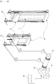
- FIG. 1 is a view illustrating a vertical continuous casting apparatus according to an embodiment of the present disclosure.
- a vertical continuous casting apparatus may include a casting mold 10 formed to vertically support a cast piece 1 to be continuously cast, and a horizontal platen 20 disposed under the casting mold 10 and supporting the cast piece. Movable sheaves 21 may be formed on both sides of the horizontal platen 20.
- the movable sheaves 21 may be interlocked with fixed sheaves 30.
- the fixed sheaves 30 may be fixed to an upper portion of the casting mold 10 in a position in which they do not interfere with the casting mold 10.
- the fixed sheaves 30 may be positioned directly above the movable sheaves 21 formed on both sides of the horizontal platen 20.
- the movable sheaves 21 on both sides of the horizontal platen 20 may be connected to upper sheaves 5 by wires, and ends of the wires may be connected to and wound around a drum 41 via the upper sheaves 5.
- the drum 41 may be connected to a speed reducer 7, and the speed reducer 7 may be connected to a motor 43.
- the motor 43 may be configured to generate torque in accordance with a speed control value of the motor 43 output from a controller 50.
- Wires may be wound on the movable sheave 21 formed on both sides of the horizontal platen 20, respectively, and a pair of wires among the wires may be wound around the drum 41.
- the speed reducer 42 may rotate the drum 41 by reducing rotational force of the motor 43.
- the drum 41 may rotate, and accordingly, a pair of wires may be wound or unwound.
- movement of the movable sheaves may be controlled by winding or unwinding the wire wound around the drum 41. Therefore, it is possible to control the horizontal platen 20 to move in a vertical direction, while maintaining the horizontal position thereof.
- the vertical continuous casting apparatus may carry out motor torque compensation control by weight and distance compensation control by expansion of the wire.
- the torque compensation control may be performed to compensate for torque transmitted to the motor 43 by weight of the horizontal platen 20 vertically supporting the cast piece 1, and weight of the cast piece 1 continuously increasing, during casting.
- the distance compensation control may be performed to compensate for expanding by thermal expansion of a wire between the platen of the vertical continuous casting apparatus and the upper sheave 5 by the cast piece 1 having a hot temperature, and expanding through elastic expansion of a wire by weight of the continuously increasing cast piece 1.
- FIG. 2 is a view illustrating compensation control of a vertical continuous casting apparatus according to an embodiment of the present disclosure. This compensation control may be performed by a controller 50 controlling an operation of the motor.
- a controller 50 may include a speed controller 51, a torque compensation controller 52, an integrator 53, and a distance compensation controller 54.
- a target casting speed may be determined, and a target motor speed may be calculated by applying a reduction ratio to the target casting speed. Thereafter, the calculated target rotation speed of a motor 43 may be compared with the actually measured rotation speed of the motor 43, and an error from the comparison may be reflected and input to the speed controller 51.
- the speed controller 51 may perform a proportional-differential-integral control to output a speed control value, capable of reducing the error.
- the output speed control value may be added to an output of the torque compensation controller 52.
- the rotation speed of the motor 43 may be divided by the reduction ratio to calculate a casting speed, and the divided results may be integrated with time of the entire casting using the integrator 53.
- the distance compensation controller 54 may perform elastic expansion compensation and thermal expansion compensation, based on wire length and wire temperature information, to compensate for the performed results in addition to output of the integrator 53.
- the casting speed of the vertical continuous casting apparatus may be stably controlled, and the head position of the cast piece may be precisely predicted and controlled, at the same time, using the torque compensation controller 52 and the distance compensation controller 54.
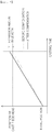
- FIG. 3 is a graph illustrating amounts of change in load torque and motor torque, as weight of a cast piece increases, and the present disclosure will be described further with reference to the figure.
- the motor torque may be calculated by summing the output of the speed compensation controller 51 and the output of the torque compensation controller 52, which may find a change in a tendency opposite to the load torque.
- the motor torque may increases in the opposite direction thereto, such that influence of an increase in weight of the cast piece 1 may be reduced.
- the distance compensation controller 54 may consider an amount of elastic expansion of the wire caused by weight of the cast piece 1 continuously increasing and an amount of thermal expansion of the wire caused by temperature of the cast piece 1 having a hot temperature. Therefore, a head position of the cast piece may be predicted accurately.
- an amount of elastic expansion in length of the wire relative to an increase in weight of the cast piece 1 may be expressed by the following Equation 3:
- Elastic Expansion mm W ⁇ L / E ⁇ A
- W is a load of the cast piece
- L is the total length of the wires (mm)
- E is an elasticity modulus (kg/mm 2 )
- A is an effective cross-sectional area of the wires (mm 2 ).
- ⁇ t may be a value determined by an experimental value.
- FIG. 4 is a graph illustrating a head position of a cast piece, depending on expansion amount of a wire, as weight of a cast piece increases, and the present disclosure will be described further with reference to the figure.
- a head position of the cast piece may become continuously high.
- a dotted line represents a case in which distance compensation control is not performed
- a solid line represents a case in which distance compensation control is performed.
- the present disclosure may perform drawing of the cast piece more precisely by performing the distance compensation control in this way.
- vibrations may be caused when the cast piece is drawn out.
- vibrations affect the casting mold 10
- frictional force may be generated on the cast piece 1, to affect the casting speed.
- an embodiment of the present disclosure may stabilize the influence of the casting speed caused by such vibration.
- FIG. 5 is a view illustrating frictional force applied to a cast piece by vibrations, and illustrates, first, influence of the vibrations.
- Frictional force may be induced on four sides determined by areas of contact between the casting mold 10 and the cast piece 1, a height (H), a width (W), and a depth (T1) .
- the casting may be performed equal to or longer than the casting mold vibration period setting reference for preventing occurrence of the hunting of the casting speed by the vibration of the cast piece due to the frictional force transmitted to the cast piece by the periodic mold vibrations.
- the vibration period of the casting mold may be set to be larger than a value calculated by the following Equation 6: Vibration Period f Hz > F / 2 ⁇ VMr
- F frictional force to be predicted between the casting mold 10 and the cast piece
- V is a casting speed (m/min)
- M is a mass of the cast piece
- r is DV/V maximum permissible casting speed variations.
- the vibration period may be adjusted to reduce influence of the casting speed due to the vibrations of the casting mold 10.
- FIG. 6 is a view illustrating an embodiment in which a vibration period increases to reduce influence of casting speed due to vibration of a casting mold.
- the vibration period is 41 cpm (cycles per minute), for example, when the casting mold 10 is vibrated in 41 cpm, hunting errors of the casting speed may increase by +/- 4% or more.
- the vibration period increases to 120 cpm, the hunting errors of the casting speed may be greatly reduced.
- FIG. 7 is a flowchart illustrating a control method for a vertical continuous casting apparatus according to an embodiment of the present disclosure.
- a control method for a vertical continuous casting apparatus to be described below may be carried out in the vertical continuous casting apparatus described above with reference to FIGS. 1 to 6 . Therefore, it can be easily understood with reference to the above description with reference to FIGS. 1 to 6 .
- the vertical continuous casting apparatus may apply a reduction ratio to a target casting speed to calculate a target motor speed (S510).
- the vertical continuous casting apparatus may compare the target motor speed with an actually measured motor speed, and reflecting an error obtained therefrom to output a speed control value (S520).
- the vertical continuous casting apparatus may perform torque compensation control by weight on the speed control value (S530).
- the vertical continuous casting apparatus may calculate torque of the motor caused by weight of the horizontal platen; and may calculate torque of the motor caused by a continuously increasing weight of the cast piece during casting.
- the vertical continuous casting apparatus may further include performing distance compensation control by reflecting thermal expansion of a wire caused by a temperature of the cast piece and elastic expansion of a wire caused by a continuously increasing weight of the cast piece (S540).
- the vertical continuous casting apparatus may prevent the hunting of the casting speed of the cast piece due to the frictional force transmitted to the cast piece by the periodic mold vibrations.
- a casting mold vibration period setting reference may be set, and the casting may be performed equal to or longer than this reference.
- the vertical continuous casting apparatus may further perform setting a casting mold vibration period setting reference, and vibrating the casting mold with a vibration period equal to or longer than the casting mold vibration period setting reference, to prevent the hunting of the casting speed.
- the casting mold vibration period setting reference may be calculated by the following equation: f Hz > F / 2 ⁇ VMr where F is frictional force to be predicted between the casting mold and the cast piece, V is a casting speed (m/min), M is a mass of the cast piece, and r is DV/V maximum permissible casting speed variation.
- Frictional Force F ⁇ ⁇ rH ⁇ H W + T where H is a length of the casting mold, W is a width of the casting mold, and T is a thickness of the cast piece.
- torque compensation control by the weight and the tension acting on the wire connected to the lower portion of the platen, and distance compensation control by expansion of the wire may be performed to provide an effect of accurately performing casting.
- the head position of the cast piece may be accurately calculated by reflecting the elastic expansion in length of the wire.
- the casting mold vibration period setting reference for preventing the hunting of the casting speed of the cast piece due to the frictional force transmitted to the cast piece by the periodic mold vibrations may be provided, and the casting mold with the vibration period equal to or longer than the casting mold vibration period setting reference may be vibrated, to prevent the hunting of the casting speed.
- FIG. 8 is a schematic block diagram of a vertical continuous casting apparatus according to another embodiment of the present disclosure.
- a vertical continuous casting apparatus may include a casting mold 10, a horizontal platen 20, a driver 40, a controller 50, and a tension generator 60.
- the casting mold 10 may be formed to vertically support a cast piece 1 to be continuously cast, and a horizontal platen 20 disposed under the casting mold 10 and supporting the cast piece 1.
- Movable sheaves 21 may be formed on both sides of the horizontal platen 20.
- the movable sheaves 21 may be interlocked with fixed sheaves 30.
- the fixed sheaves 30 may be fixed to an upper portion of the casting mold 10 in a position in which it does not interfere with the casting mold 10.
- the fixed sheaves 30 may be positioned directly above the movable sheaves 21 formed on both sides of the horizontal platen 20.
- the driver 40 may move the horizontal platen 20 in the vertical direction, and the controller 50 may control the driver 40.
- the movable sheaves 21 on both sides of the horizontal platen 20 may be connected to upper sheaves 30 by wires (a), and ends of the wires may be connected to and wound around a drum 41 via the upper sheaves 30.
- the drum 41 may be connected to a speed reducer 42, and the speed reducer 42 may be connected to a motor 43.
- the motor 43 may be configured to generate torque in accordance with a speed control value of the motor 43 output from a controller 50.
- the wires (a) may be wound on the movable sheave 21 formed on both sides of the horizontal platen 20, respectively, and such a pair of wires may be wound around the drum 41.
- the speed reducer 42 may rotate the drum 41 by reducing rotational force of the motor 43.
- the controller 50 may control the rotation of the motor 43, and wind or unwind the wire wound around the drum 41, to control movement of the movable sheaves 21. Therefore, it is possible to control the horizontal platen 20 to move in a vertical direction, while maintaining the horizontal position thereof.
- the tension generator 60 may apply tension in the vertical direction (force pulling in the vertical direction) in the lower portion of the horizontal platen 20.
- the tension generator 60 may include a tension adjuster 61.
- the tension adjuster 61 may control movement of a wire (b) between a lower fixed sheave 61d and a supporting roller 61e in the vertical direction, and may include a tension roller 61c, a cylinder loader 61b, and a tension adjusting cylinder 61a to control tension acting on the wire (b).
- the tension generator 60 may further include a drum 62, a speed reducer 63, and a motor 64.
- the controller 50 may control a speed of the motor 64.
- the speed reducer 63 may rotate the drum 62 by reducing rotational force of the motor 64. Since the wire (b) between the lower fixed sheave 61d and the supporting roller 61e is wound around the drum 62, the controller 50 may control the tension applied in the vertical direction in the lower portion of the horizontal platen 20, by controlling the rotation of the motor 64 and by winding or unwinding the wire (b) wound on the drum 62.
- FIG. 9 is a schematic block diagram of a vertical continuous casting apparatus according to another embodiment of the present disclosure.
- a driver 40 and a tension generator 60 of a vertical continuous casting apparatus may share a drum 41, a speed reducer 42, and a motor 43.
- wires may be wound on movable sheaves 21 formed on both sides of a horizontal platen 20, and the pair of wires may be wound around the drum 41, and wires between a lower fixed sheave 61d and a supporting roller 61e may be wound around the drum 41 as well.
- a controller 50 may rotate the motor 43 and the speed reducer 42 may reduce the rotational force of the motor 43 to rotate the drum 41.
- the drum 41 may rotate, and accordingly, the pair of wires may be wound or unwound.
- the controller 50 may control rotation of the motor 43, and wind or unwind the wire wound around the drum 41, to control movement of the movable sheave 21. Therefore, it is possible to control the horizontal platen 20 to move in a vertical direction, while maintaining the horizontal position thereof, and to control the tension applied in the vertical direction in a lower portion of the horizontal platen 20.
- FIG. 10 is a schematic block diagram illustrating a principle of a vertical continuous casting apparatus according to another embodiment of the present disclosure.
- tension of a wire caused by a lower fixed sheave 61d and a supporting roller 61e may fluctuate.
- the fluctuated tension may act on a wire connected to a lower portion of a horizontal platen 20, and may act on a drum 41 or 62 as well.
- Tension acting on the wire refers to T, when the tension roller 61c is located on a solid line, while tension acting on the wire refers to T', when the tension roller 61c is moved to a position of a dotted line. In this case, T' may be greater than the tension when it is located on the solid line.
- FIG. 11 is a schematic block diagram of a controller of a vertical continuous casting apparatus according to another embodiment of the present disclosure.
- a controller 50 may include a speed controller 51, a torque compensation controller 52, an integrator 53, and a distance compensation controller 54.
- a target casting speed may be determined, and a target motor speed may be calculated by applying a reduction ratio to the target casting speed. Thereafter, the calculated target rotation speed of a motor may be compared with the actually measured rotation speed of the motor, and an error from the comparison may be reflected and input to the speed controller 51.
- the speed controller 51 may perform a proportional-differential-integral control to output a speed control value, capable of reducing the error.
- the output speed control value may be added to an output of the torque compensation controller 52.
- the rotation speed of the motor may be divided by the reduction ratio to calculate a casting speed, and the divided results may be integrated with time of the entire casting using the integrator 53.
- the distance compensation controller 54 may perform elastic expansion compensation and thermal expansion compensation, based on wire length and wire temperature information, to compensate for the performed results in addition to output of the integrator 53.
- the casting speed of the vertical continuous casting apparatus may be stably controlled, and the head position of the cast piece may be precisely predicted and controlled, at the same time, using the torque compensation controller 52 and the distance compensation controller 54.
- the torque compensation control may be performed with the sum of torque in which the tension applied to the wire connected to the lower portion of the platen is transmitted to the motor, in addition to torque caused by weight of the horizontal platen 20 and weight of the cast piece.
- the torque compensation control may be performed with the sum of torque caused by weight of the horizontal platen 20 itself, and weight of the cast piece 1 which increases as the casting is performed, and torque in which the tension applied to the wire connected to the lower portion of the platen is transmitted to the motor.
- the motor torque may be calculated by summing the output of the speed compensation controller 51 and the output of the torque compensation controller 52, which may find a change in a tendency opposite to the load torque.
- the motor torque may increases in the opposite direction thereto, such that influence of an increase in weight of the cast piece 1 may be reduced.
- the distance compensation controller 54 may consider an amount of elastic expansion of the wire caused by weight of the cast piece 1 continuously increasing and an amount of thermal expansion of the wire caused by temperature of the cast piece 1 having a hot temperature. Therefore, a head position of the cast piece may be predicted accurately.
- an amount of elastic expansion in length of the wire relative to an increase in weight of the cast piece 1, and an amount of elastic expansion in length of the wire with respect to the tensile force due to the tension T acting on the wire connected to the lower portion of the platen may be expressed by the following Equation 10:
- Elastic Expansion mm W + T / N ⁇ 2 ⁇ L / E ⁇ A
- W is a load of the cast piece
- L is the total length of the wires (mm)
- E an elasticity modulus (kg/mm 2 )
- A is an effective cross-sectional area of the wires (mm 2 )
- T is tension
- N the number of wire between the upper sheaves and the platen.
- tension may be applied to a wire connected to a lower portion of the horizontal platen to forcibly draw the platen out, and casting speed and position of the cast piece may stably be controlled, even when load acting on the wire connected to the lower portion fluctuates.
Landscapes
- Engineering & Computer Science (AREA)
- Mechanical Engineering (AREA)
- Continuous Casting (AREA)
Abstract
Description
- The present disclosure relates to a vertical continuous casting apparatus and a control method therefor.
- In general, vertical continuous casting technology is being developed as a steel manufacturing technique. Such vertical continuous casting technology has advantages of being capable of continuous casting with a relatively large cross-section, and producing a cast piece several times larger than a conventional casting apparatus.
- Meanwhile, since a cast piece in a vertical continuous casting technology has a relatively large size and a relatively long length, weight of the cast piece may be relatively heavy to tens of tons. Therefore, influences of the weight and the temperature of the cast piece may affect the manufacturing environment of the cast piece, and such influences may cause an error in the production of the cast piece.
- Such prior art may be easily understood with reference to Korean Patent Publication No.
2016-5019943 2012-0154883 2012-0032538 - An aspect of the present disclosure is to provide a vertical continuous casting apparatus, capable of performing torque compensation control by weight and distance compensation control by expansion of the wire, performing accurate and stable casting by providing a vibration period setting reference for preventing hunting of a casting speed of a cast piece due to force transmitted to the cast piece by periodic casting mold vibrations, and applying tension to a lower portion of a horizontal platen; and a control method therefor.
- In order to overcome the above-described problems, according to an aspect of the present disclosure, a vertical continuous casting apparatus may include: a casting mold configured to vertically support a cast piece to be continuously cast; a horizontal platen having movable sheaves provided on both sides thereof and supporting the cast piece in a vertical direction; a motor controlling movement of the movable sheaves via wires; and a controller controlling casting by torque compensation control of the motor by weight and distance compensation control by expansion of the wires.
- According to an aspect of the present disclosure, a control method for a vertical continuous casting apparatus, carried out in the vertical continuous casting apparatus continuously casting a cast piece in a vertical direction by using a horizontal platen provided with a movable sheave may include: applying a reduction ratio to a target casting speed to calculate a target motor speed; comparing the target motor speed with an actually measured motor speed, and reflecting an error obtained therefrom to output a speed control value; and performing torque compensation control by weight on the speed control value.
- According to an aspect of the present disclosure, torque compensation control by weight and distance compensation control by expansion of a wire may be performed to provide an effect of accurately performing casting.
- According to an aspect of the present disclosure, when weight of a cast piece continuously increases, a head position of the cast piece may be accurately calculated by reflecting elastic expansion in length of a wire.
- According to an aspect of the present disclosure, a casting mold vibration period setting reference for preventing hunting of a casting speed of a cast piece due to frictional force transmitted to the cast piece by periodic mold vibrations may be provided, and a casting mold with a vibration period equal to or longer than the casting mold vibration period setting reference may be vibrated, to prevent hunting of a casting speed.
- According to an aspect of the present disclosure, when a horizontal platen is tilted by an amount of expansion (thermal expansion, or expansion due to load) of left and right wires supporting the platen, or when vertical movement of the platen is inhibited by thermal deformation of a guiding post supporting movement of the horizontal platen to generate jamming or the like, tension (force) may be applied to a wire connected to a lower portion of the horizontal platen to forcibly draw the platen out, and casting speed and position of the cast piece may stably be controlled, even when load acting on the wire connected to the lower portion fluctuates.
-
-
FIG. 1 is a view illustrating a vertical continuous casting apparatus according to an embodiment of the present disclosure. -
FIG. 2 is a view illustrating compensation control of a vertical continuous casting apparatus according to an embodiment of the present disclosure. -
FIG. 3 is a graph illustrating amounts of change in load torque and motor torque, as weight of a cast piece increases. -
FIG. 4 is a graph illustrating a head position of a cast piece, depending on expansion amount of a wire, as weight of a cast piece increases. -
FIG. 5 is a view illustrating frictional force applied to a cast piece by vibrations. -
FIG. 6 is a view illustrating an embodiment in which a vibration period increases to reduce influence of casting speed due to vibration of a casting mold. -
FIG. 7 is a flowchart illustrating a control method for a vertical continuous casting apparatus according to an embodiment of the present disclosure. -
FIG. 8 is a schematic block diagram of a vertical continuous casting apparatus according to another embodiment of the present disclosure. -
FIG. 9 is a schematic block diagram of a vertical continuous casting apparatus according to another embodiment of the present disclosure. -
FIG. 10 is a schematic block diagram illustrating a principle of a vertical continuous casting apparatus according to another embodiment of the present disclosure. -
FIG. 11 is a schematic block diagram of a controller of a vertical continuous casting apparatus according to another embodiment of the present disclosure. - Hereinafter, preferred embodiments of the present disclosure will be described in detail with reference to the accompanying drawings, in order that those skilled in the art can easily carry out the present disclosure.
- A vertical continuous casting apparatus is capable of continuous casting with a relatively large cross-section, and producing a cast piece several times larger than a conventional casting apparatus. Further, since a length of the cast piece is equal to or longer than 10m, weight of the cast piece may be relatively heavy to tens of tons.
- Therefore, as an embodiment of the present disclosure, a vertical continuous casting apparatus capable of moving a cast piece in a vertical direction, and capable of drawing out with relatively high vertical stability by using a sheave is described.
- First,
FIG. 1 is a view illustrating a vertical continuous casting apparatus according to an embodiment of the present disclosure. - Referring to
FIG. 1 , a vertical continuous casting apparatus may include acasting mold 10 formed to vertically support acast piece 1 to be continuously cast, and ahorizontal platen 20 disposed under thecasting mold 10 and supporting the cast piece.Movable sheaves 21 may be formed on both sides of thehorizontal platen 20. - The
movable sheaves 21 may be interlocked withfixed sheaves 30. Thefixed sheaves 30 may be fixed to an upper portion of thecasting mold 10 in a position in which they do not interfere with thecasting mold 10. Thefixed sheaves 30 may be positioned directly above themovable sheaves 21 formed on both sides of thehorizontal platen 20. - The
movable sheaves 21 on both sides of thehorizontal platen 20 may be connected toupper sheaves 5 by wires, and ends of the wires may be connected to and wound around adrum 41 via theupper sheaves 5. Thedrum 41 may be connected to a speed reducer 7, and the speed reducer 7 may be connected to amotor 43. Themotor 43 may be configured to generate torque in accordance with a speed control value of themotor 43 output from acontroller 50. - Wires may be wound on the
movable sheave 21 formed on both sides of thehorizontal platen 20, respectively, and a pair of wires among the wires may be wound around thedrum 41. Thespeed reducer 42 may rotate thedrum 41 by reducing rotational force of themotor 43. - Therefore, as the
motor 43 rotates, thedrum 41 may rotate, and accordingly, a pair of wires may be wound or unwound. As a result, by controlling the rotation of themotor 43, movement of the movable sheaves may be controlled by winding or unwinding the wire wound around thedrum 41. Therefore, it is possible to control thehorizontal platen 20 to move in a vertical direction, while maintaining the horizontal position thereof. - During production of the cast piece, as above, compensation for the rotation of the motor may be performed for more precise casting. For example, the vertical continuous casting apparatus may carry out motor torque compensation control by weight and distance compensation control by expansion of the wire.
- The torque compensation control may be performed to compensate for torque transmitted to the
motor 43 by weight of thehorizontal platen 20 vertically supporting thecast piece 1, and weight of thecast piece 1 continuously increasing, during casting. - The distance compensation control may be performed to compensate for expanding by thermal expansion of a wire between the platen of the vertical continuous casting apparatus and the
upper sheave 5 by thecast piece 1 having a hot temperature, and expanding through elastic expansion of a wire by weight of the continuously increasingcast piece 1. -
FIG. 2 is a view illustrating compensation control of a vertical continuous casting apparatus according to an embodiment of the present disclosure. This compensation control may be performed by acontroller 50 controlling an operation of the motor. - Referring to
FIG. 3 , acontroller 50 may include aspeed controller 51, atorque compensation controller 52, anintegrator 53, and adistance compensation controller 54. - In the vertical continuous casting apparatus, first, a target casting speed may be determined, and a target motor speed may be calculated by applying a reduction ratio to the target casting speed. Thereafter, the calculated target rotation speed of a
motor 43 may be compared with the actually measured rotation speed of themotor 43, and an error from the comparison may be reflected and input to thespeed controller 51. - The
speed controller 51 may perform a proportional-differential-integral control to output a speed control value, capable of reducing the error. The output speed control value may be added to an output of thetorque compensation controller 52. - Next, the rotation speed of the
motor 43 may be divided by the reduction ratio to calculate a casting speed, and the divided results may be integrated with time of the entire casting using theintegrator 53. - Thereafter, the
distance compensation controller 54 may perform elastic expansion compensation and thermal expansion compensation, based on wire length and wire temperature information, to compensate for the performed results in addition to output of theintegrator 53. - Therefore, the casting speed of the vertical continuous casting apparatus may be stably controlled, and the head position of the cast piece may be precisely predicted and controlled, at the same time, using the
torque compensation controller 52 and thedistance compensation controller 54. - A predictive calculation method of the
torque compensation controller 52 and thedistance compensation controller 54 will be described in more detail. - In the
torque compensation controller 52, torque caused by weight of thehorizontal platen 20 itself, and weight of thecast piece 1 which increases as the casting is performed may be calculated as illustrated in the following Equation 1:
- where M0 is a mass of the
horizontal platen 20, M(t) is a mass of the cast piece, g is a gravitational acceleration, and D is a diameter of thedrum 41. - M(t) may be calculated by the following Equation 2:
-
FIG. 3 is a graph illustrating amounts of change in load torque and motor torque, as weight of a cast piece increases, and the present disclosure will be described further with reference to the figure. - The motor torque may be calculated by summing the output of the
speed compensation controller 51 and the output of thetorque compensation controller 52, which may find a change in a tendency opposite to the load torque. - For example, when the load torque due to the load increases, the motor torque may increases in the opposite direction thereto, such that influence of an increase in weight of the
cast piece 1 may be reduced. - Hereinafter, a prediction calculation method of the
distance compensation controller 54 will be described in more detail. - The
distance compensation controller 54 may consider an amount of elastic expansion of the wire caused by weight of thecast piece 1 continuously increasing and an amount of thermal expansion of the wire caused by temperature of thecast piece 1 having a hot temperature. Therefore, a head position of the cast piece may be predicted accurately. - First, an amount of elastic expansion in length of the wire relative to an increase in weight of the
cast piece 1 may be expressed by the following Equation 3:
where W is a load of the cast piece, L is the total length of the wires (mm), E is an elasticity modulus (kg/mm2), and A is an effective cross-sectional area of the wires (mm2). - Meanwhile, an amount of thermal expansion of the wire according to influence of the temperature may be expressed by the following Equation 4:

where L is a length of the wires (mm), ∝ is a thermal expansion coefficient (kg/mm2) of the wires, and is an increase amount in a temperature of the wires. Δt may be a value determined by an experimental value. - Considering the above-described expansion of the wire, the head position of the cast piece may be calculated by the following Equation 5:

-
FIG. 4 is a graph illustrating a head position of a cast piece, depending on expansion amount of a wire, as weight of a cast piece increases, and the present disclosure will be described further with reference to the figure. - As the casting is performed, starting from an initial head position of a cast piece, a head position of the cast piece may become continuously high.
- In the illustrated graph, a dotted line represents a case in which distance compensation control is not performed, and a solid line represents a case in which distance compensation control is performed.
- As above, when the distance compensation control is not performed, an error in a head position of the cast piece may occur, and the present disclosure may perform drawing of the cast piece more precisely by performing the distance compensation control in this way.
- Meanwhile, vibrations may be caused when the cast piece is drawn out. In this case, when such vibrations affect the casting
mold 10, frictional force may be generated on thecast piece 1, to affect the casting speed. - Therefore, an embodiment of the present disclosure may stabilize the influence of the casting speed caused by such vibration.
-
FIG. 5 is a view illustrating frictional force applied to a cast piece by vibrations, and illustrates, first, influence of the vibrations. - When a casting
mold 10 vibrates (Fv), such vibrations may cause frictional force between the castingmold 10 and acast piece 1. For convenience of explanation, the figure illustrates a case in which a single side among sides is opened. Frictional force (F2) may be induced on four sides determined by areas of contact between the castingmold 10 and thecast piece 1, a height (H), a width (W), and a depth (T1) . - A method of stabilizing a casting speed by reducing a hunting of the casting speed caused by the influence of such frictional force will be described. For example, the casting may be performed equal to or longer than the casting mold vibration period setting reference for preventing occurrence of the hunting of the casting speed by the vibration of the cast piece due to the frictional force transmitted to the cast piece by the periodic mold vibrations.
- First, when a permissible rate of change of the casting speed relative to the target casting speed is g, the vibration period of the casting mold may be set to be larger than a value calculated by the following Equation 6:

- where F is frictional force to be predicted between the casting
mold 10 and the cast piece, V is a casting speed (m/min), M is a mass of the cast piece, and r is DV/V maximum permissible casting speed variations. - The frictional force F may be determined by multiplying force of a molten steel in the casting
mold 10 acting perpendicularly on a surface of the castingmold 10 by a frictional coefficient, which may be calculated as illustrated in the following Equation 7:
where H is a length of the castingmold 10, W is a width of the castingmold 10, and T is a thickness of the cast piece. - As a result, the vibration period may be adjusted to reduce influence of the casting speed due to the vibrations of the casting
mold 10. -
FIG. 6 is a view illustrating an embodiment in which a vibration period increases to reduce influence of casting speed due to vibration of a casting mold. - As illustrated in the figure, when the vibration period is 41 cpm (cycles per minute), for example, when the casting
mold 10 is vibrated in 41 cpm, hunting errors of the casting speed may increase by +/- 4% or more. When the vibration period increases to 120 cpm, the hunting errors of the casting speed may be greatly reduced. -
FIG. 7 is a flowchart illustrating a control method for a vertical continuous casting apparatus according to an embodiment of the present disclosure. - A control method for a vertical continuous casting apparatus to be described below may be carried out in the vertical continuous casting apparatus described above with reference to
FIGS. 1 to 6 . Therefore, it can be easily understood with reference to the above description with reference toFIGS. 1 to 6 . - Referring to
FIG. 7 , the vertical continuous casting apparatus may apply a reduction ratio to a target casting speed to calculate a target motor speed (S510). - Thereafter, the vertical continuous casting apparatus may compare the target motor speed with an actually measured motor speed, and reflecting an error obtained therefrom to output a speed control value (S520).
- The vertical continuous casting apparatus may perform torque compensation control by weight on the speed control value (S530).
- In an embodiment of S530, the vertical continuous casting apparatus may calculate torque of the motor caused by weight of the horizontal platen; and may calculate torque of the motor caused by a continuously increasing weight of the cast piece during casting.
- Thereafter, the vertical continuous casting apparatus may further include performing distance compensation control by reflecting thermal expansion of a wire caused by a temperature of the cast piece and elastic expansion of a wire caused by a continuously increasing weight of the cast piece (S540).
- In an embodiment, the vertical continuous casting apparatus may prevent the hunting of the casting speed of the cast piece due to the frictional force transmitted to the cast piece by the periodic mold vibrations. For this, a casting mold vibration period setting reference may be set, and the casting may be performed equal to or longer than this reference.
- For example, the vertical continuous casting apparatus may further perform setting a casting mold vibration period setting reference, and vibrating the casting mold with a vibration period equal to or longer than the casting mold vibration period setting reference, to prevent the hunting of the casting speed.
- The casting mold vibration period setting reference may be calculated by the following equation:

where F is frictional force to be predicted between the casting mold and the cast piece, V is a casting speed (m/min), M is a mass of the cast piece, and r is DV/V maximum permissible casting speed variation. - Meanwhile, the frictional force F may be determined by the following equation:

where H is a length of the casting mold, W is a width of the casting mold, and T is a thickness of the cast piece. - As described above, according to the present disclosure, torque compensation control by the weight and the tension acting on the wire connected to the lower portion of the platen, and distance compensation control by expansion of the wire may be performed to provide an effect of accurately performing casting.
- Further, according to the present disclosure, when the weight of the cast piece continuously increases, the head position of the cast piece may be accurately calculated by reflecting the elastic expansion in length of the wire.
- In addition, according to the present disclosure, the casting mold vibration period setting reference for preventing the hunting of the casting speed of the cast piece due to the frictional force transmitted to the cast piece by the periodic mold vibrations may be provided, and the casting mold with the vibration period equal to or longer than the casting mold vibration period setting reference may be vibrated, to prevent the hunting of the casting speed.
-
FIG. 8 is a schematic block diagram of a vertical continuous casting apparatus according to another embodiment of the present disclosure. - Referring to
FIG. 8 , a vertical continuous casting apparatus according to another embodiment of the present disclosure may include a castingmold 10, ahorizontal platen 20, adriver 40, acontroller 50, and atension generator 60. - The casting
mold 10 may be formed to vertically support acast piece 1 to be continuously cast, and ahorizontal platen 20 disposed under the castingmold 10 and supporting thecast piece 1.Movable sheaves 21 may be formed on both sides of thehorizontal platen 20. - The
movable sheaves 21 may be interlocked with fixedsheaves 30. The fixed sheaves 30 may be fixed to an upper portion of the castingmold 10 in a position in which it does not interfere with the castingmold 10. The fixed sheaves 30 may be positioned directly above themovable sheaves 21 formed on both sides of thehorizontal platen 20. - The
driver 40 may move thehorizontal platen 20 in the vertical direction, and thecontroller 50 may control thedriver 40. - The
movable sheaves 21 on both sides of thehorizontal platen 20 may be connected toupper sheaves 30 by wires (a), and ends of the wires may be connected to and wound around adrum 41 via theupper sheaves 30. - The
drum 41 may be connected to aspeed reducer 42, and thespeed reducer 42 may be connected to amotor 43. Themotor 43 may be configured to generate torque in accordance with a speed control value of themotor 43 output from acontroller 50. - The wires (a) may be wound on the
movable sheave 21 formed on both sides of thehorizontal platen 20, respectively, and such a pair of wires may be wound around thedrum 41. Thespeed reducer 42 may rotate thedrum 41 by reducing rotational force of themotor 43. - Therefore, as the
motor 43 rotates, thedrum 41 may rotate, and accordingly, the pair of wires (a) may be wound or unwound. As a result, thecontroller 50 may control the rotation of themotor 43, and wind or unwind the wire wound around thedrum 41, to control movement of themovable sheaves 21. Therefore, it is possible to control thehorizontal platen 20 to move in a vertical direction, while maintaining the horizontal position thereof. - The
tension generator 60 may apply tension in the vertical direction (force pulling in the vertical direction) in the lower portion of thehorizontal platen 20. - The
tension generator 60 may include atension adjuster 61. Thetension adjuster 61 may control movement of a wire (b) between a lower fixedsheave 61d and a supportingroller 61e in the vertical direction, and may include atension roller 61c, acylinder loader 61b, and atension adjusting cylinder 61a to control tension acting on the wire (b). - The
tension generator 60 may further include adrum 62, aspeed reducer 63, and amotor 64. Thecontroller 50 may control a speed of themotor 64. Thespeed reducer 63 may rotate thedrum 62 by reducing rotational force of themotor 64. Since the wire (b) between the lower fixedsheave 61d and the supportingroller 61e is wound around thedrum 62, thecontroller 50 may control the tension applied in the vertical direction in the lower portion of thehorizontal platen 20, by controlling the rotation of themotor 64 and by winding or unwinding the wire (b) wound on thedrum 62. -
FIG. 9 is a schematic block diagram of a vertical continuous casting apparatus according to another embodiment of the present disclosure. - Referring to
FIG. 9 , adriver 40 and atension generator 60 of a vertical continuous casting apparatus, according to another embodiment of the present disclosure, may share adrum 41, aspeed reducer 42, and amotor 43. - For example, wires may be wound on
movable sheaves 21 formed on both sides of ahorizontal platen 20, and the pair of wires may be wound around thedrum 41, and wires between a lower fixedsheave 61d and a supportingroller 61e may be wound around thedrum 41 as well. - A
controller 50 may rotate themotor 43 and thespeed reducer 42 may reduce the rotational force of themotor 43 to rotate thedrum 41. - As the
motor 43 rotates, thedrum 41 may rotate, and accordingly, the pair of wires may be wound or unwound. As a result, thecontroller 50 may control rotation of themotor 43, and wind or unwind the wire wound around thedrum 41, to control movement of themovable sheave 21. Therefore, it is possible to control thehorizontal platen 20 to move in a vertical direction, while maintaining the horizontal position thereof, and to control the tension applied in the vertical direction in a lower portion of thehorizontal platen 20. - Since configuration and functions of a casting
mold 10, thehorizontal platen 20, and atension adjuster 61 of atension generator 60, except for the above, as illustrated inFIG. 9 , are the same as and similar to those illustrated inFIG. 8 , detailed explanations thereof will be omitted. -
FIG. 10 is a schematic block diagram illustrating a principle of a vertical continuous casting apparatus according to another embodiment of the present disclosure. - Referring to
FIG. 10 , when atension roller 61c connected to atension adjusting cylinder 61a and acylinder loader 61b is moved in a vertical direction, tension of a wire caused by a lower fixedsheave 61d and a supportingroller 61e may fluctuate. In this case, the fluctuated tension may act on a wire connected to a lower portion of ahorizontal platen 20, and may act on adrum tension roller 61c is located on a solid line, while tension acting on the wire refers to T', when thetension roller 61c is moved to a position of a dotted line. In this case, T' may be greater than the tension when it is located on the solid line. -
FIG. 11 is a schematic block diagram of a controller of a vertical continuous casting apparatus according to another embodiment of the present disclosure. - Referring to
FIG. 11 , acontroller 50 may include aspeed controller 51, atorque compensation controller 52, anintegrator 53, and adistance compensation controller 54. - In the vertical continuous casting apparatus, first, a target casting speed may be determined, and a target motor speed may be calculated by applying a reduction ratio to the target casting speed. Thereafter, the calculated target rotation speed of a motor may be compared with the actually measured rotation speed of the motor, and an error from the comparison may be reflected and input to the
speed controller 51. - The
speed controller 51 may perform a proportional-differential-integral control to output a speed control value, capable of reducing the error. The output speed control value may be added to an output of thetorque compensation controller 52. - Next, the rotation speed of the motor may be divided by the reduction ratio to calculate a casting speed, and the divided results may be integrated with time of the entire casting using the
integrator 53. - Thereafter, the
distance compensation controller 54 may perform elastic expansion compensation and thermal expansion compensation, based on wire length and wire temperature information, to compensate for the performed results in addition to output of theintegrator 53. - Therefore, the casting speed of the vertical continuous casting apparatus may be stably controlled, and the head position of the cast piece may be precisely predicted and controlled, at the same time, using the
torque compensation controller 52 and thedistance compensation controller 54. - A predictive calculation method of the
torque compensation controller 52 and thedistance compensation controller 54 will be described in more detail. - In the
torque compensation controller 52, the torque compensation control may be performed with the sum of torque in which the tension applied to the wire connected to the lower portion of the platen is transmitted to the motor, in addition to torque caused by weight of thehorizontal platen 20 and weight of the cast piece. - In the
torque compensation controller 52, the torque compensation control may be performed with the sum of torque caused by weight of thehorizontal platen 20 itself, and weight of thecast piece 1 which increases as the casting is performed, and torque in which the tension applied to the wire connected to the lower portion of the platen is transmitted to the motor. - The torque compensation may be calculated as illustrated in the following Equation 8:
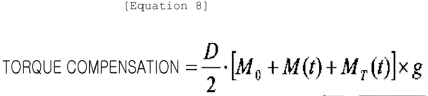
- where M0 is a mass of the
horizontal platen 20, M(t) is a mass of the cast piece, g is a gravitational acceleration, and D is a diameter of thedrum 41. - M(t) may be calculated by the above Equation 2.
- Meanwhile, MT (t) may be a torque by the tension acting on the wire in the lower portion of the platen, and may be calculated by the following Equation 9:

where T is applied tension, and R is a radius of the drum. - The motor torque may be calculated by summing the output of the
speed compensation controller 51 and the output of thetorque compensation controller 52, which may find a change in a tendency opposite to the load torque. - For example, when the load torque due to the load increases, the motor torque may increases in the opposite direction thereto, such that influence of an increase in weight of the
cast piece 1 may be reduced. - Hereinafter, a prediction calculation method of the
distance compensation controller 54 will be described in more detail. - The
distance compensation controller 54 may consider an amount of elastic expansion of the wire caused by weight of thecast piece 1 continuously increasing and an amount of thermal expansion of the wire caused by temperature of thecast piece 1 having a hot temperature. Therefore, a head position of the cast piece may be predicted accurately. - First, an amount of elastic expansion in length of the wire relative to an increase in weight of the
cast piece 1, and an amount of elastic expansion in length of the wire with respect to the tensile force due to the tension T acting on the wire connected to the lower portion of the platen may be expressed by the following Equation 10:
where W is a load of the cast piece, L is the total length of the wires (mm), E is an elasticity modulus (kg/mm2), A is an effective cross-sectional area of the wires (mm2), T is tension, N is the number of wire between the upper sheaves and the platen. - Meanwhile, since the amount of thermal expansion of the wire due to the influence of the temperature may be the same as in the above Equation 4, and the position of the head position of the cast piece may be the same as in the
above Equation 5, duplicate explanations thereof will be omitted. Similarly, since the vibration period and the frictional force of the casting mold may be the same as in the above Equations 6 and 7, duplicate explanations thereof will be omitted. - As described above, according to the present disclosure, when a horizontal platen is tilted by an amount of expansion (thermal expansion, or expansion due to load) of left and right wires supporting the platen, or when vertical movement of the platen is inhibited by thermal deformation of a guiding post supporting movement of the horizontal platen to generate jamming or the like, tension (force) may be applied to a wire connected to a lower portion of the horizontal platen to forcibly draw the platen out, and casting speed and position of the cast piece may stably be controlled, even when load acting on the wire connected to the lower portion fluctuates.
- It can be to be understood that both the foregoing general description and the following detailed description may be exemplary and explanatory, and may be not intended to limit the present disclosure to the particular forms disclosed. It can be understood by those skilled in the art that various changes in form and details may be made therein without departing from the spirit and scope of the present disclosure as defined by the appended claims.

where v(t) is a casting speed, A is an area of the casting
Claims (19)
- A vertical continuous casting apparatus comprising:a casting mold configured to vertically support a cast piece to be continuously cast;a horizontal platen having movable sheaves provided on both sides thereof and supporting the cast piece in a vertical direction;a motor controlling movement of the movable sheaves via wires; anda controller controlling casting by torque compensation control of the motor by weight and distance compensation control by expansion of the wires.
- The vertical continuous casting apparatus according claim 1, wherein the controller performs the torque compensation control by way of reflecting a weight of the horizontal platen and a continuously increasing weight of the cast piece during the casting.
- The vertical continuous casting apparatus according claim 2, wherein a torque compensation value is determined according to the following equation:

- The vertical continuous casting apparatus according claim 3, wherein the controller determines the M(t) according to the following equation:

- The vertical continuous casting apparatus according claim 1, wherein the controller performs the distance compensation control by way of reflecting thermal expansion caused on the wires by a temperature of the cast piece and elastic expansion caused on the wires by a continuously increasing weight of the cast piece.
- The vertical continuous casting apparatus according claim 5, wherein the controller determines a value of the elastic expansion according to the following equation:

- The vertical continuous casting apparatus according claim 5, wherein the controller determines a value of the thermal expansion according to the following equation,

- The vertical continuous casting apparatus according claim 1, further comprising a tension generator for providing a tension in the vertical direction through a motor for driving a wire connected to a lower portion of the horizontal platen.
- The vertical continuous casting apparatus according claim 8, wherein the tension generator comprises a tension adjuster adjusting the tension,
wherein the tension adjuster comprises:a lower fixed sheave and a support roller supporting the wire with disposing the wire therebetween; anda tension roller, a cylinder loader, and a tension adjustable cylinder, controlling a tension acting on the wire through vertical movement control of the wire. - The vertical continuous casting apparatus according claim 9, wherein the controller further compensates torque of the motor according to the tension transmitted to the horizontal platen through a wire connected to a lower portion of the horizontal platen.
- The vertical continuous casting apparatus according claim 10, wherein the controller further controls the casting by way of the torque compensation control of the motor by the weight of the cast piece and the distance compensation control by expansion of the wire and a wire of the tension generator.
- The vertical continuous casting apparatus according claim 10, wherein the tension generator shares the motor.
- A control method for a vertical continuous casting apparatus, carried out in the vertical continuous casting apparatus continuously casting a cast piece in a vertical direction by using a horizontal platen provided with a movable sheave, comprising: by a controller,
applying a reduction ratio to a target casting speed to calculate a target motor speed;
comparing the target motor speed with an actually measured motor speed, and reflecting an error obtained therefrom to output a speed control value; and
performing torque compensation control by weight on the speed control value. - The control method according claim 13, wherein the performing the torque compensation control comprises:calculating torque of the motor caused by weight of the horizontal platen; andcalculating torque of the motor caused by a continuously increasing weight of the cast piece during casting.
- The control method according claim 13, further comprising performing distance compensation control by reflecting thermal expansion caused on a wire by a temperature of the cast piece and elastic expansion caused on a wire by a continuously increasing weight of the cast piece.
- The control method according claim 13, further comprising setting a casting mold vibration period setting reference, and vibrating a mold with a vibration period equal to or longer than the mold vibration period setting reference to prevent hunting of a casting speed,
wherein the casting mold vibration period setting reference is calculated by the following equation:
- The control method according claim 16, wherein the frictional force F is determined by the following equation:

- The control method according claim 14, wherein the performing the torque compensation control further comprises calculating torque of the motor caused by a tension transmitted to the horizontal platen through a wire connected to a lower portion of the horizontal platen.
- The control method according claim 15, wherein the performing the distance compensation control further comprises performing the distance compensation control by further reflecting elastic expansion induced in the wire by tension applied in the vertical direction, to a wire connected to a lower portion of the horizontal platen.
Applications Claiming Priority (3)
| Application Number | Priority Date | Filing Date | Title |
|---|---|---|---|
| KR1020160176802A KR101879088B1 (en) | 2016-12-22 | 2016-12-22 | Continuous casting equipment of vertical type and control method thereof |
| KR1020170171382A KR102031431B1 (en) | 2017-12-13 | 2017-12-13 | Continuous casting equipment of vertical type |
| PCT/KR2017/015409 WO2018117765A1 (en) | 2016-12-22 | 2017-12-22 | Vertical continuous casting apparatus and control method therefor |
Publications (2)
| Publication Number | Publication Date |
|---|---|
| EP3560628A1 true EP3560628A1 (en) | 2019-10-30 |
| EP3560628A4 EP3560628A4 (en) | 2019-10-30 |
Family
ID=62627001
Family Applications (1)
| Application Number | Title | Priority Date | Filing Date |
|---|---|---|---|
| EP17883501.3A Withdrawn EP3560628A4 (en) | 2016-12-22 | 2017-12-22 | Vertical continuous casting apparatus and control method therefor |
Country Status (4)
| Country | Link |
|---|---|
| EP (1) | EP3560628A4 (en) |
| JP (1) | JP2020503175A (en) |
| CN (1) | CN110099762A (en) |
| WO (1) | WO2018117765A1 (en) |
Family Cites Families (16)
| Publication number | Priority date | Publication date | Assignee | Title |
|---|---|---|---|---|
| FR1578961A (en) * | 1968-05-14 | 1969-08-22 | ||
| JPS61108452A (en) * | 1984-10-31 | 1986-05-27 | Kawasaki Steel Corp | Coiling method of quickly cooled thin strip |
| JPH07144255A (en) * | 1993-11-22 | 1995-06-06 | Kobe Steel Ltd | Vertical semicontinuous casting device for large cross section cast slab and carrying out method of cast slab |
| JP3146904B2 (en) * | 1995-02-07 | 2001-03-19 | 株式会社神戸製鋼所 | Vertical continuous casting method for large section slabs |
| JPH10156505A (en) * | 1996-11-25 | 1998-06-16 | Kawasaki Steel Corp | Vibration method of vertical continuous casting mold |
| CN1204987C (en) * | 2000-03-29 | 2005-06-08 | 机械工业部西安重型机械研究所 | Design method and equipment of oblique knockout system for vertical conticaster |
| JP4613448B2 (en) * | 2001-06-01 | 2011-01-19 | 大同特殊鋼株式会社 | Vertical casting method and apparatus |
| JP2007302928A (en) * | 2006-05-10 | 2007-11-22 | Sumitomo Electric Ind Ltd | Conveying mechanism for continuous processing of long base material, processing apparatus using the same, and long member obtained thereby |
| CN201008955Y (en) * | 2007-02-14 | 2008-01-23 | 南昌长力钢铁股份有限公司 | Continuous casting billet fixed weight shearing device |
| CN101653823B (en) * | 2009-07-11 | 2011-06-29 | 山西太钢不锈钢股份有限公司 | Control method for oblique running-out and receiving of slabs of vertical continuous caster |
| EP2456752A2 (en) | 2009-07-24 | 2012-05-30 | ratiopharm GmbH | Process for producing fingolimod salts |
| KR101149373B1 (en) * | 2009-12-24 | 2012-05-30 | 주식회사 포스코 | Apparatus for casting of vertical type and method for casting using it |
| JP4970529B2 (en) * | 2009-12-28 | 2012-07-11 | 株式会社神戸製鋼所 | Slab guide device for continuous casting equipment |
| JP6343949B2 (en) * | 2014-02-04 | 2018-06-20 | 日立金属株式会社 | Slab drawing apparatus and slab drawing method |
| JP6399340B2 (en) * | 2014-08-12 | 2018-10-03 | 大同特殊鋼株式会社 | Breakout detection method and detection device for continuous casting |
| CN105081253A (en) * | 2015-08-27 | 2015-11-25 | 河北钢铁股份有限公司 | Horizontal blank ejection device for vertical-type continuous casting machine |
-
2017
- 2017-12-22 EP EP17883501.3A patent/EP3560628A4/en not_active Withdrawn
- 2017-12-22 CN CN201780079750.4A patent/CN110099762A/en active Pending
- 2017-12-22 WO PCT/KR2017/015409 patent/WO2018117765A1/en not_active Ceased
- 2017-12-22 JP JP2019532671A patent/JP2020503175A/en active Pending
Also Published As
| Publication number | Publication date |
|---|---|
| CN110099762A (en) | 2019-08-06 |
| WO2018117765A1 (en) | 2018-06-28 |
| EP3560628A4 (en) | 2019-10-30 |
| JP2020503175A (en) | 2020-01-30 |
Similar Documents
| Publication | Publication Date | Title |
|---|---|---|
| CN1052803A (en) | The thickness control system of milling train | |
| US20090314873A1 (en) | Method for the operation of a coiling device used for coiling or uncoiling a metallic strip, and control device and coiling device therefor | |
| US8062578B2 (en) | Tilting-type automatic pouring method and a medium that stores programs to control the tilting of a ladle | |
| JP2727007B2 (en) | Method and apparatus for vibrating continuous casting mold | |
| KR101879088B1 (en) | Continuous casting equipment of vertical type and control method thereof | |
| JP2016093829A (en) | Rolling control device, rolling control method, and rolling control program | |
| JP6966417B2 (en) | Rolling control device, rolling control method, and rolling control program | |
| KR102031431B1 (en) | Continuous casting equipment of vertical type | |
| JP6308927B2 (en) | Rolling control device, rolling control method, and rolling control program | |
| CN110099762A (en) | Vertical continuous casting equipment and the control method for the equipment | |
| JP5085226B2 (en) | Winding method for steel strip | |
| JP3449305B2 (en) | Tension control method and apparatus for strip material | |
| JP2005262237A (en) | Metal sheet manufacturing apparatus and manufacturing method | |
| JP5452575B2 (en) | Control method of rolling mill | |
| KR100406383B1 (en) | Method for controlling tension of a thin strip at a twin-roll strip caster | |
| JP6373800B2 (en) | Rolling control device, rolling control method, and rolling control program | |
| JP3895962B2 (en) | Rolling mill control device, method, computer program, and computer-readable recording medium | |
| JP2811847B2 (en) | Rolling mill thickness control device | |
| JPH0578502B2 (en) | ||
| JPH01205815A (en) | Method and apparatus for controlling rotary tension fluctuation of take-up reel | |
| JPS61235056A (en) | System for controlling molten steel level in continuous casting machine | |
| JP3506195B2 (en) | Continuous casting method | |
| JP2014001055A (en) | Power assist device, and its control method and program | |
| JPH10323714A (en) | Method and apparatus for winding or paying out metal strip coil | |
| KR100775290B1 (en) | Surface level control device in continuous casting process |
Legal Events
| Date | Code | Title | Description |
|---|---|---|---|
| PUAI | Public reference made under article 153(3) epc to a published international application that has entered the european phase |
Free format text: ORIGINAL CODE: 0009012 |
|
| 17P | Request for examination filed |
Effective date: 20190712 |
|
| A4 | Supplementary search report drawn up and despatched |
Effective date: 20190820 |
|
| AK | Designated contracting states |
Kind code of ref document: A1 Designated state(s): AL AT BE BG CH CY CZ DE DK EE ES FI FR GB GR HR HU IE IS IT LI LT LU LV MC MK MT NL NO PL PT RO RS SE SI SK SM TR |
|
| AX | Request for extension of the european patent |
Extension state: BA ME |
|
| RIN1 | Information on inventor provided before grant (corrected) |
Inventor name: SHIN, KI-TAE Inventor name: JEONG, CHANG-KI |
|
| DAV | Request for validation of the european patent (deleted) | ||
| DAX | Request for extension of the european patent (deleted) | ||
| 17Q | First examination report despatched |
Effective date: 20200422 |
|
| STAA | Information on the status of an ep patent application or granted ep patent |
Free format text: STATUS: THE APPLICATION IS DEEMED TO BE WITHDRAWN |
|
| 18D | Application deemed to be withdrawn |
Effective date: 20200903 |