EP3560550A1 - Neuromodulation lead for reducing interactions with mri - Google Patents
Neuromodulation lead for reducing interactions with mri Download PDFInfo
- Publication number
- EP3560550A1 EP3560550A1 EP18172976.5A EP18172976A EP3560550A1 EP 3560550 A1 EP3560550 A1 EP 3560550A1 EP 18172976 A EP18172976 A EP 18172976A EP 3560550 A1 EP3560550 A1 EP 3560550A1
- Authority
- EP
- European Patent Office
- Prior art keywords
- conductor
- lead
- conductors
- electrical insulator
- insulator
- Prior art date
- Legal status (The legal status is an assumption and is not a legal conclusion. Google has not performed a legal analysis and makes no representation as to the accuracy of the status listed.)
- Withdrawn
Links
Images
Classifications
-
- A—HUMAN NECESSITIES
- A61—MEDICAL OR VETERINARY SCIENCE; HYGIENE
- A61N—ELECTROTHERAPY; MAGNETOTHERAPY; RADIATION THERAPY; ULTRASOUND THERAPY
- A61N1/00—Electrotherapy; Circuits therefor
- A61N1/02—Details
- A61N1/08—Arrangements or circuits for monitoring, protecting, controlling or indicating
- A61N1/086—Magnetic resonance imaging [MRI] compatible leads
-
- A—HUMAN NECESSITIES
- A61—MEDICAL OR VETERINARY SCIENCE; HYGIENE
- A61N—ELECTROTHERAPY; MAGNETOTHERAPY; RADIATION THERAPY; ULTRASOUND THERAPY
- A61N1/00—Electrotherapy; Circuits therefor
- A61N1/02—Details
- A61N1/04—Electrodes
- A61N1/05—Electrodes for implantation or insertion into the body, e.g. heart electrode
-
- A—HUMAN NECESSITIES
- A61—MEDICAL OR VETERINARY SCIENCE; HYGIENE
- A61N—ELECTROTHERAPY; MAGNETOTHERAPY; RADIATION THERAPY; ULTRASOUND THERAPY
- A61N1/00—Electrotherapy; Circuits therefor
- A61N1/02—Details
- A61N1/04—Electrodes
- A61N1/05—Electrodes for implantation or insertion into the body, e.g. heart electrode
- A61N1/0551—Spinal or peripheral nerve electrodes
-
- G—PHYSICS
- G01—MEASURING; TESTING
- G01R—MEASURING ELECTRIC VARIABLES; MEASURING MAGNETIC VARIABLES
- G01R33/00—Arrangements or instruments for measuring magnetic variables
- G01R33/20—Arrangements or instruments for measuring magnetic variables involving magnetic resonance
- G01R33/28—Details of apparatus provided for in groups G01R33/44 - G01R33/64
- G01R33/32—Excitation or detection systems, e.g. using radio frequency signals
- G01R33/36—Electrical details, e.g. matching or coupling of the coil to the receiver
- G01R33/3685—Means for reducing sheath currents, e.g. RF traps, baluns
-
- H—ELECTRICITY
- H01—ELECTRIC ELEMENTS
- H01B—CABLES; CONDUCTORS; INSULATORS; SELECTION OF MATERIALS FOR THEIR CONDUCTIVE, INSULATING OR DIELECTRIC PROPERTIES
- H01B13/00—Apparatus or processes specially adapted for manufacturing conductors or cables
- H01B13/06—Insulating conductors or cables
-
- H—ELECTRICITY
- H01—ELECTRIC ELEMENTS
- H01B—CABLES; CONDUCTORS; INSULATORS; SELECTION OF MATERIALS FOR THEIR CONDUCTIVE, INSULATING OR DIELECTRIC PROPERTIES
- H01B7/00—Insulated conductors or cables characterised by their form
- H01B7/0009—Details relating to the conductive cores
-
- H—ELECTRICITY
- H01—ELECTRIC ELEMENTS
- H01B—CABLES; CONDUCTORS; INSULATORS; SELECTION OF MATERIALS FOR THEIR CONDUCTIVE, INSULATING OR DIELECTRIC PROPERTIES
- H01B7/00—Insulated conductors or cables characterised by their form
- H01B7/02—Disposition of insulation
- H01B7/0291—Disposition of insulation comprising two or more layers of insulation having different electrical properties
-
- H—ELECTRICITY
- H01—ELECTRIC ELEMENTS
- H01F—MAGNETS; INDUCTANCES; TRANSFORMERS; SELECTION OF MATERIALS FOR THEIR MAGNETIC PROPERTIES
- H01F27/00—Details of transformers or inductances, in general
- H01F27/28—Coils; Windings; Conductive connections
- H01F27/2823—Wires
- H01F27/2828—Construction of conductive connections, of leads
-
- G—PHYSICS
- G01—MEASURING; TESTING
- G01R—MEASURING ELECTRIC VARIABLES; MEASURING MAGNETIC VARIABLES
- G01R33/00—Arrangements or instruments for measuring magnetic variables
- G01R33/20—Arrangements or instruments for measuring magnetic variables involving magnetic resonance
- G01R33/28—Details of apparatus provided for in groups G01R33/44 - G01R33/64
- G01R33/288—Provisions within MR facilities for enhancing safety during MR, e.g. reduction of the specific absorption rate [SAR], detection of ferromagnetic objects in the scanner room
Definitions
- MRI Magnetic Resonance Imaging
- RF Radio Frequency
- US 9,399,129 describes a medical lead having multiple conductors which are wound in an interleaved manner. Furthermore, US 2016/0331960 A1 describes different materials suited as electrical insulation for leads.
- a lead for transporting an electrical current comprising at least a first and a second conductor, wherein the first conductor and the second conductor each comprise an electrically conducting core (comprising e.g. at least one wire or several wires) that is surrounded by an electrical insulator, wherein the electrical insulator of the first conductor consists of a first material, and wherein the electrical insulator of the second conductor consists of a second material, wherein the first material differs from the second material.
- an electrically conducting core comprising e.g. at least one wire or several wires
- the respective core can e.g. be formed by a single wire or a plurality of adjacent wires.
- the present invention allows to tune (e.g. during the design phase) of each conductor's resonant frequency to e.g. ensure that none of the conductors are in resonance at the used or any useable MR frequencies depending on Lamor frequencies.
- the present invention allows to tune the individual conductor such that MR-Conditional FBS labeling is enabled.
- the first material and the second material are chosen such that the lead comprises a resonance frequency that is different from a frequency used in an MRI device, particularly different from 64 MHz (e.g. for 1.5 T MRI devices) or different from 128 MHz (e.g. for 3T MRI devices).
- the first material and the second material are selected from the group of the following materials: a ceramics, a polymer, ETFE, PFA, PTFE, polyimide, aluminum oxide, barium titanate, titanium dioxide.
- said conductors of the lead e.g. the first and the second conductor, each form a helical coil.
- the respective conductor can also extend linearly.
- two or more conductors of the lead can be braided or wound in an interleaved manner.
- the lead comprises a plurality of conductors including said first and said second conductor, wherein each conductor of said plurality of conductors other than the first and the second conductor also comprises an electrically conducting core (e.g. at least one wire or several wires) that is surrounded by an electrical insulator formed out of the first material or out of the second material, or out of a further material different from the first and the second material.
- an electrically conducting core e.g. at least one wire or several wires
- said plurality of conductors may consist of at least eight, or at least 16 conductors.
- the lead comprises a lead body insulator surrounding each individual conductor.
- the lead body insulator can be formed out of or can comprise polyurethane or silicone.
- the lead comprises at least one further conductor formed by a non-insulated (i.e. bare) electrically conducting member, which is electrically insulated with respect to its surrounding by means of electrical insulators of adjacent conductors of the lead and/or by means of said lead body insulator.
- electrically conducting member may be formed by at least one or several wires.
- said first and said second conductor are co-radial and/or co-axial helical coils.
- each remaining conductor can be a co-radial and/or a co-axial helical coil with respect to another conductor of the lead.
- two adjacent conductors form co-radial helical coils if they are arranged one inside the other and have the same radius and pitch.
- two co-axial helical coils (or conductors) are co-axial in case they have a common coil axis around which the respective coil (or conductor) is wound.
- said conductors form an inner coil structure and a co-axial outer coil structure surrounding the inner coil structure, wherein each coil structure comprises a plurality of conductors, each conductor forming a helical coil, wherein particularly the helical coils (conductors) of the inner coil structure are co-radial and/or wherein the helical coils (conductors) of the outer coil structure are co-radial.
- two coil structures are co-axial in case they have a common coil axis around which the conductors of the respective coil structure are wound.
- the lead is a medical lead (i.e. a lead of a medical device).
- the lead is an implantable medical lead.
- the lead is an electrode lead comprising a plurality of electrodes.
- Each electrode may form a section, particularly a circumferential section, of an outer surface of the lead, wherein each electrode is electrically connected to one of the conductors.
- the lead comprises at least two electrodes, particularly at least eight electrodes, particularly at least 16 electrodes.
- the lead is an SCS lead, i.e. a lead adapted for spinal cord stimulation (SCS).
- SCS spinal cord stimulation
- a method for producing a lead particularly a lead according to the present invention, wherein at least a first and a second conductor are provided, wherein the first conductor and the second conductor each comprise an electrically conducting core (see e.g. above) that is surrounded by an electrical insulator, wherein the electrical insulator of the first conductor is made out of a first material, and wherein the electrical insulator of the second conductor is made out of a second material, wherein the first material differs from the second material, and wherein said conductors are surrounded by an outer lead body insulator.
- the first material and the second material are chosen such that the respective conductor comprises a resonance frequency that is different from a pre-defined frequency used in an MRI device, particularly different from 64 MHz (e.g. for 1.5 T MRI devices) or different from 128 MHz (e.g. for 3T MRI devices), see also above.
- the invention allows providing a MR Conditional full body scan SCS lead which is less complex than known solutions.
- the invention allows for shifting the resonant frequency of each conductor in the lead to ensure all conductors avoid resonance at MR frequencies.
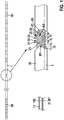
- a lead 1 according to the present invention comprises at least a first and a second conductor 12, 13, wherein the first conductor 12 and the second conductor 13 each comprise an electrically conducting core 100 that is surrounded by an electrical insulator 21 (as shown on the lower left side of Fig 1 ), wherein the electrical insulator 22 of the first conductor 12 consists of a first material M1, and wherein - analogously - the electrical insulator 23 of the second conductor 13 consists of a second material M2, wherein the first material M1 differs from the second material M2.
- the lead 1 can comprises a lead body insulator 30 surrounding each individual conductor 12, 13 for providing further insulation and protection of the single conductors 12, 13.
- conductors 11, 12,...,18 of lead 1 need inductance L and capacitance C.
- One way to incorporate inductance and capacitance into a lead 1 is to coil the conductors 11, 12 along the length of the lead 1 as shown in Fig. 1 , which turns each conductor 11, 12 into a coil (or solenoid structure) with winding to winding parasitic capacitance.
- the LC combination creates a filter that blocks the high frequency MRI induced RF signals, while allowing the low frequency biological signals to pass unimpeded.
- Most SCS leads available today use straight conductors, which have very little inductance.
- the lead shown in Fig. 1 can be a co-radial SCS lead 1 with 8 electrodes 40 on a distal end of the lead 1, wherein each of the electrodes 40 is connected via one of the conductors 11, 18 to a connector contact 50 arranged on the proximal end of the lead 1.
- the close-up section in the bottom right of Fig. 1 shows the coiled conductors 11, 18.
- three conductors 11, 12 and 14 are coated with an electrical insulator 21, 22, 24 consisting of a first material M1, while the five remaining conductors 13, 15, 16, 17, 18 are coated with an electrical insulator 23, 25, 26, 27, 28 consisting of a second material M2 that differs from the first material M1.
- RF frequencies for MRI devices are e.g. ⁇ 64 MHz for 1.5 T machines, and ⁇ 128 MHz for 3T machines. If a conductor 11, 12 on the lead 1 shown in Fig. 1 resonates at MRI RF frequencies then the impedance of the lead 1 drops dramatically at these frequencies and very little energy is dissipated in the lead 1. The result is much more MRI induced current flowing through the lead 1 which results in much more RF heating at the electrodes 40. Avoiding resonance is particularly challenging for leads 1, particularly SCS leads 1, which typically have 8 different conductors 11, 18 connected to 8 different electrodes 40.
- Each conductor 11, 18 has its own resonance frequency which is distinct from the resonance frequency of the other conductors because each electrode 40 is typically located at a different distance along the lead 1, and hence the conductor 11, 18 connected to each electrode 40 has a different length. So, an 8 conductor lead 1 is much more challenging to design to avoid resonance than a typical 2 conductor cardiac lead because there are 4 times as many conductors that need to be designed to avoid resonance. Worse yet, some SCS leads incorporate paddle electrode arrays with 16 or more separate conductors connecting 16 or more different electrodes. These large number of electrodes 30 multiply the odds that at least one conductor 11, 18 connected to one electrode 40 will be in resonance at MRI frequencies.
- an embodiment of the present invention particularly uses coiled conductors 11, 18 for a lead 1, particularly an SCS lead 1, with at least two different materials M1, M2 as electrical insulator 21, 28 on the individual conductor core/wires 100 as shown e.g. in Fig. 1 .
- the coiled conductors 11, 18 give inductance because the coiling creates a solenoid structure, and the coiling also gives capacitance due to increased conductor length, which is capacitive coupled to neighboring windings.
- the different insulators 21, 28 allow each conductor's self-resonance to be selected during the design phase to avoid MRI frequencies. Some conductors have material M1 as insulator material and some conductors have material M2 as insulator material.
- the dielectric constant ⁇ r is a function of the insulation material M1, M2 surrounding the respective conductor 11., 18.
- the preferred materials M1, M2 for insulating the individual lead conductors 11., 18 are e.g. ETFE, PFA, and PTFE.
- the dielectric constant ⁇ r for these materials are shown in Table 1 below.
- ETFE has a dielectric constant about 25% greater than PTFE or PFA. Therefore, in one embodiment ETFE is used on at least one conductor 11, 18, while PFA or PTFE are used on the other conductors. Table 1: ETFE PFA PTFE Dielectric Constant 2.6 2.1 2.1
- 8 different conductors connected to 8 different electrodes are all wound co-radially as shown in Fig. 1 .
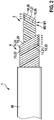
- Fig. 2 shows a further embodiment of a lead 1 according to the present invention also using two different insulator materials M1, M2.
- two conductors 11, 12 of an outer coil 4 structure comprised of 5 conductors 11, 12, 13, 14, 15 in form of co-radial helical coils comprise electrical insulators 21, 22 formed out of a first material M1.
- the lead comprises an inner coil structure 3 surrounded by the co-axial outer coil structure 4, wherein the inner coil structure 3 is comprised of three conductors 16, 17, 18 in form of co-radial helical coils, wherein one conductor 17 is formed out of the first Material M1.
- the other conductors 13, 14, 15, and 16, 18 comprise insulators 23, 24, 25, 26, 28 made out of a different second material M2.
- a co-axial/co-radial design is used for the conductors 11, 18.
- This construction is more complicated than the co-radial design shown in Figure 1 , but it has several advantages.
- the outer coil 4 has less conductors than the co-radial design shown in Fig. 1 (since some of the conductors are moved to the inner coil 3), and less conductors means that each conductor has a finer pitch.
- the finer pitch results in a much greater inductance (inductance is proportional to the square of the pitch), which results in a better MRI induce RF current rejection.
- the conductors 16, 18 in the inner coil structure 3 are shielded by the outer coil structure 4.
- the greater average capacitance results in a better (lower cut off frequency) low pass (LC) filter.
- the inductive and capacitive coupling mechanisms result in more current sharing between the conductors at MRI frequencies. This helps average out the MRI induced currents on each conductor, eliminating peaks.
- At least one conductor e.g. of the conductors 11, 18 shown in Fig. 1 or 2
- the lead body insulator/tube 30 which is typically silicone or polyurethane.
- This embodiment not only changes the resonance frequency of the conductor(s) with no separate insulation, but also allows all the conductors 11, 18 to be packaged closer together, resulting in a tighter winding pitch and higher overall inductance for each conductor. Particularly, at most, every other conductor can be without insulation.
- the present invention allows for visual identification between conductors during the manufacturing process (e.g. to make sure that the appropriate conductor gets welded to the appropriate contact).
- colorants can be added to one or more of the coatings to make it readily apparent which conductor is which.
- the pitch can be increased which increases the inductance and improves MRI performance. In one embodiment of this, only every other conductor is insulated.
Landscapes
- Health & Medical Sciences (AREA)
- Engineering & Computer Science (AREA)
- Radiology & Medical Imaging (AREA)
- Veterinary Medicine (AREA)
- Public Health (AREA)
- General Health & Medical Sciences (AREA)
- Heart & Thoracic Surgery (AREA)
- Animal Behavior & Ethology (AREA)
- Biomedical Technology (AREA)
- Nuclear Medicine, Radiotherapy & Molecular Imaging (AREA)
- Life Sciences & Earth Sciences (AREA)
- Neurology (AREA)
- Power Engineering (AREA)
- Cardiology (AREA)
- Physics & Mathematics (AREA)
- Manufacturing & Machinery (AREA)
- Neurosurgery (AREA)
- Orthopedic Medicine & Surgery (AREA)
- Condensed Matter Physics & Semiconductors (AREA)
- General Physics & Mathematics (AREA)
- Electrotherapy Devices (AREA)
Abstract
The present invention relates to a lead (1) comprising at least a first and a second conductor (12, 13), wherein the first conductor (11) and the second conductor (13) each comprise an electrically conducting core (100) that is surrounded by an electrical insulator (22, 23), wherein the electrical insulator (22) of the first conductor (12) consists of a first material (M1), and wherein the electrical insulator (23) of the second conductor (13) consists of a second material (M2), wherein the first material (M1) differs from the second material (M2). The first material (M1) and the second material (M2) are chosen such that the respective conductor (12, 13) comprises a resonance frequency that is different from a frequency used in an MRI device.
Description
- Conventional designs of percutaneous SCS leads are in general not suitable for MR-Conditional Full Body Scan (FBS) labeling.
- MRI (Magnetic Resonance Imaging) devices put out very large RF (Radio Frequency) fields during operation. The energy in these fields is picked up by conductors in the SCS lead. If the leads do not have mechanisms for dissipating this energy, then the energy reaches the electrodes of the lead where it is dissipated as heat. Disadvantageously, such an electrode heating can damage tissue of the patient.
-
US 9,399,129 US 2016/0331960 A1 describes different materials suited as electrical insulation for leads. - Based on the above, there is a desire for providing comparatively simple leads, particularly SCS lead, which do not suffer from electrode heating when subjected to MRI, and which are particularly MR conditional Full Body Scan.
- This objective is solved by a lead having the features of claim 1. Particular embodiments of this aspect of the present invention are stated in the corresponding sub claims.
- According to claim 1, a lead for transporting an electrical current is disclosed, comprising at least a first and a second conductor, wherein the first conductor and the second conductor each comprise an electrically conducting core (comprising e.g. at least one wire or several wires) that is surrounded by an electrical insulator, wherein the electrical insulator of the first conductor consists of a first material, and wherein the electrical insulator of the second conductor consists of a second material, wherein the first material differs from the second material.
- The respective core can e.g. be formed by a single wire or a plurality of adjacent wires.
- Advantageously, by using different materials for said electrical insulations, the present invention allows to tune (e.g. during the design phase) of each conductor's resonant frequency to e.g. ensure that none of the conductors are in resonance at the used or any useable MR frequencies depending on Lamor frequencies. Particular, in this way, the present invention allows to tune the individual conductor such that MR-Conditional FBS labeling is enabled.
- According to an embodiment of the present invention, the first material and the second material are chosen such that the lead comprises a resonance frequency that is different from a frequency used in an MRI device, particularly different from 64 MHz (e.g. for 1.5 T MRI devices) or different from 128 MHz (e.g. for 3T MRI devices).
- Furthermore, according to an embodiment of the present invention, the first material and the second material are selected from the group of the following materials: a ceramics, a polymer, ETFE, PFA, PTFE, polyimide, aluminum oxide, barium titanate, titanium dioxide.
- Furthermore, according to an embodiment of the present invention, said conductors of the lead, e.g. the first and the second conductor, each form a helical coil.
- According to a further embodiment, the respective conductor can also extend linearly. Furthermore, alternatively, two or more conductors of the lead can be braided or wound in an interleaved manner.
- Further, according to an embodiment of the present invention, the lead comprises a plurality of conductors including said first and said second conductor, wherein each conductor of said plurality of conductors other than the first and the second conductor also comprises an electrically conducting core (e.g. at least one wire or several wires) that is surrounded by an electrical insulator formed out of the first material or out of the second material, or out of a further material different from the first and the second material.
- Furthermore, according to an embodiment of the present invention, said plurality of conductors may consist of at least eight, or at least 16 conductors.
- Furthermore, according to an embodiment of the present invention, the lead comprises a lead body insulator surrounding each individual conductor. The lead body insulator can be formed out of or can comprise polyurethane or silicone.
- Furthermore, according to an embodiment of the present invention, the lead comprises at least one further conductor formed by a non-insulated (i.e. bare) electrically conducting member, which is electrically insulated with respect to its surrounding by means of electrical insulators of adjacent conductors of the lead and/or by means of said lead body insulator. Particularly that electrically conducting member may be formed by at least one or several wires.
- Furthermore, according to an embodiment of the present invention, said first and said second conductor are co-radial and/or co-axial helical coils. Besides said first and second conductor also each remaining conductor (see above) can be a co-radial and/or a co-axial helical coil with respect to another conductor of the lead.
- Particularly, two adjacent conductors form co-radial helical coils if they are arranged one inside the other and have the same radius and pitch. Further, particularly, two co-axial helical coils (or conductors) are co-axial in case they have a common coil axis around which the respective coil (or conductor) is wound.
- Furthermore, according to an embodiment of the present invention, said conductors (e.g. the first and the second conductor and particularly the remaining conductors if present) form an inner coil structure and a co-axial outer coil structure surrounding the inner coil structure, wherein each coil structure comprises a plurality of conductors, each conductor forming a helical coil, wherein particularly the helical coils (conductors) of the inner coil structure are co-radial and/or wherein the helical coils (conductors) of the outer coil structure are co-radial.
- Also here, particularly, two coil structures are co-axial in case they have a common coil axis around which the conductors of the respective coil structure are wound.
- Furthermore, according to an embodiment of the present invention, the lead is a medical lead (i.e. a lead of a medical device). Particularly, the lead is an implantable medical lead.
- Furthermore, according to an embodiment of the present invention, the lead is an electrode lead comprising a plurality of electrodes. Each electrode may form a section, particularly a circumferential section, of an outer surface of the lead, wherein each electrode is electrically connected to one of the conductors. Particularly the lead comprises at least two electrodes, particularly at least eight electrodes, particularly at least 16 electrodes.
- Furthermore, according to an embodiment of the present invention, the lead is an SCS lead, i.e. a lead adapted for spinal cord stimulation (SCS).
- According to a further aspect of the present invention, a method for producing a lead, particularly a lead according to the present invention, is disclosed, wherein at least a first and a second conductor are provided, wherein the first conductor and the second conductor each comprise an electrically conducting core (see e.g. above) that is surrounded by an electrical insulator, wherein the electrical insulator of the first conductor is made out of a first material, and wherein the electrical insulator of the second conductor is made out of a second material, wherein the first material differs from the second material, and wherein said conductors are surrounded by an outer lead body insulator.
- The materials that can be used are already stated above.
- Particularly, according to an embodiment of the method according to the present invention, the first material and the second material are chosen such that the respective conductor comprises a resonance frequency that is different from a pre-defined frequency used in an MRI device, particularly different from 64 MHz (e.g. for 1.5 T MRI devices) or different from 128 MHz (e.g. for 3T MRI devices), see also above.
- Particularly, the invention allows providing a MR Conditional full body scan SCS lead which is less complex than known solutions. Particularly, the invention allows for shifting the resonant frequency of each conductor in the lead to ensure all conductors avoid resonance at MR frequencies.
- Further features and embodiments of the present invention are described below with reference to the Figures, wherein
- Fig. 1
- shows a lead comprising co-radial conductors having electrical insulations, wherein each insulation can consist of one of at least two different materials; and
- Fig. 2
- shows a lead comprising an outer and a co-axial an inner coil structure, each structure comprising a plurality of co-radial conductors having electrical insulations, wherein each insulation can consist of one of at least two different materials.
- According to
Fig. 1 a lead 1 according to the present invention comprises at least a first and asecond conductor 12, 13, wherein thefirst conductor 12 and the second conductor 13 each comprise an electrically conductingcore 100 that is surrounded by an electrical insulator 21 (as shown on the lower left side ofFig 1 ), wherein theelectrical insulator 22 of thefirst conductor 12 consists of a first material M1, and wherein - analogously - theelectrical insulator 23 of the second conductor 13 consists of a second material M2, wherein the first material M1 differs from the second material M2. - Furthermore, the lead 1 can comprises a
lead body insulator 30 surrounding eachindividual conductor 12, 13 for providing further insulation and protection of thesingle conductors 12, 13. - Now, in order to avoid RF heating during MRI,
conductors conductors Fig. 1 , which turns eachconductor - Particularly, the lead shown in
Fig. 1 can be a co-radial SCS lead 1 with 8electrodes 40 on a distal end of the lead 1, wherein each of theelectrodes 40 is connected via one of theconductors 11, 18 to aconnector contact 50 arranged on the proximal end of the lead 1. The close-up section in the bottom right ofFig. 1 shows thecoiled conductors 11, 18. In this illustration threeconductors electrical insulator electrical insulator - In addition to adding inductance and capacitance, resonance at MRI RF frequencies needs to be avoided in leads designed for MRI labeling. RF frequencies for MRI devices are e.g. ∼64 MHz for 1.5 T machines, and ∼128 MHz for 3T machines. If a
conductor Fig. 1 resonates at MRI RF frequencies then the impedance of the lead 1 drops dramatically at these frequencies and very little energy is dissipated in the lead 1. The result is much more MRI induced current flowing through the lead 1 which results in much more RF heating at theelectrodes 40. Avoiding resonance is particularly challenging for leads 1, particularly SCS leads 1, which typically have 8different conductors 11, 18 connected to 8different electrodes 40. Eachconductor 11, 18 has its own resonance frequency which is distinct from the resonance frequency of the other conductors because eachelectrode 40 is typically located at a different distance along the lead 1, and hence theconductor 11, 18 connected to eachelectrode 40 has a different length. So, an 8 conductor lead 1 is much more challenging to design to avoid resonance than a typical 2 conductor cardiac lead because there are 4 times as many conductors that need to be designed to avoid resonance. Worse yet, some SCS leads incorporate paddle electrode arrays with 16 or more separate conductors connecting 16 or more different electrodes. These large number ofelectrodes 30 multiply the odds that at least oneconductor 11, 18 connected to oneelectrode 40 will be in resonance at MRI frequencies. - To avoid such resonance frequencies, an embodiment of the present invention particularly uses
coiled conductors 11, 18 for a lead 1, particularly an SCS lead 1, with at least two different materials M1, M2 aselectrical insulator wires 100 as shown e.g. inFig. 1 . Thecoiled conductors 11, 18 give inductance because the coiling creates a solenoid structure, and the coiling also gives capacitance due to increased conductor length, which is capacitive coupled to neighboring windings. Thedifferent insulators 


conductor 11, 18, while PFA or PTFE are used on the other conductors.Table 1: ETFE PFA PTFE Dielectric Constant 2.6 2.1 2.1 - In one embodiment 8 different conductors connected to 8 different electrodes are all wound co-radially as shown in
Fig. 1 . -
Fig. 2 shows a further embodiment of a lead 1 according to the present invention also using two different insulator materials M1, M2. Here, twoconductors conductors electrical insulators insulators - Here, in the second embodiment, a co-axial/co-radial design is used for the
conductors 11, 18. In this embodiment there are two (or even more) layers of coiled conductors, namely an inner layer or coil structure 3 and an outer layer (or coil structure) 4. This construction is more complicated than the co-radial design shown inFigure 1 , but it has several advantages. First, the outer coil 4 has less conductors than the co-radial design shown inFig. 1 (since some of the conductors are moved to the inner coil 3), and less conductors means that each conductor has a finer pitch. The finer pitch results in a much greater inductance (inductance is proportional to the square of the pitch), which results in a better MRI induce RF current rejection. Second, the conductors 16, 18 in the inner coil structure 3 are shielded by the outer coil structure 4. Third, there is greater average capacitance between conductors in this design since the average distance betweenconductors 11, 18 is reduced. The reduced average distance is because of the finer pitch of both the inner and outer coil structure 3, 4 compared to the co-radial coil ofFig. 1 , and the nested arrangement of the two coil structures 3, 4 which causes coupling between the coils structures 3, 4. The greater average capacitance results in a better (lower cut off frequency) low pass (LC) filter. In addition, the inductive and capacitive coupling mechanisms result in more current sharing between the conductors at MRI frequencies. This helps average out the MRI induced currents on each conductor, eliminating peaks. One example implementation of this co-axial/co-radial design shown inFig. 2 is detailed in Table 2 below.
In another embodiment at least one conductor (e.g. of theconductors 11, 18 shown inFig. 1 or2 ) has no separate insulation around it at all (insulation to thebody 30 is still provided by the lead body insulator/tube 30 which is typically silicone or polyurethane. This embodiment not only changes the resonance frequency of the conductor(s) with no separate insulation, but also allows all theconductors 11, 18 to be packaged closer together, resulting in a tighter winding pitch and higher overall inductance for each conductor. Particularly, at most, every other conductor can be without insulation. - Particularly, having different insulation materials M1, M2 on different filars of the inner and/or outer coil structure allows fine tuning of the resonant frequency of the lead 1 for each
electrode 40. If a certain lead length leads to one ormore electrodes 40 being in electrical resonance at MRI frequencies, then the insulation material M1, M2 can be changed on that particular filar/conductor to shift the resonance away from MRI frequencies. Furthermore, the present invention allows for visual identification between conductors during the manufacturing process (e.g. to make sure that the appropriate conductor gets welded to the appropriate contact). Particularly, colorants can be added to one or more of the coatings to make it readily apparent which conductor is which. Particularly, in the above-described embodiment in which the insulation is removed altogether on one or more filars/conductors, the pitch can be increased which increases the inductance and improves MRI performance. In one embodiment of this, only every other conductor is insulated.
Claims (14)
- Lead (1) comprising at least a first and a second conductor (12, 13), wherein the first conductor (13) and the second conductor (13) each comprise an electrically conducting core (100) that is surrounded by an electrical insulator (22, 23), wherein the electrical insulator (22) of the first conductor (12) consists of a first material (M1), and wherein the electrical insulator (23) of the second conductor (13) consists of a second material (M2), wherein the first material (M1) differs from the second material (M2).
- Lead according to claim 1, wherein the first material (M1) and the second material (M2) are chosen such that the respective conductor (12, 13) comprises a resonance frequency that is different from a frequency used in an MRI device.
- Lead according to claim 1 or 2, wherein the first material (M1) and the second material (M2) are selected from the group of the following materials: a ceramics, a polymer, ETFE, PFA, PTFE, polyimide, aluminum oxide, barium titanate, titanium dioxide.
- Lead according to one of the preceding claims, wherein the first and the second conductor (12, 13) each form a helical coil.
- Lead according to one of the preceding claims, wherein the lead (1) comprises a plurality of conductors (11, 12, ..., 18) including said first and said second conductor (12, 13), wherein each conductor (11, 12, ..., 18) of said plurality of conductors other than the first and the second conductor (12, 13) also comprises an electrically conducting core (100) that is surrounded by an electrical insulator (23, 24,...) formed out of the first material (M1) or out of the second material (M2), or out of a further material different from the first and the second material (M1, M2).
- Lead according to one of the preceding claims, wherein the lead (1) comprises a lead body insulator (30) surrounding each individual conductor (11, 12,..., 18).
- Lead according to claim 6, wherein the lead (1) comprises at least one conductor formed by a non-insulated electrically conducting member, which is electrically insulated with respect to its surrounding by means of electrical insulators (21, 22) of adjacent conductors (11, 12) of the lead (1) and/or by means of said lead body insulator (30).
- Lead according to one of the preceding claims, wherein said first and said second conductor (12, 13) are co-radial and/or co-axial helical coils.
- The lead according to claim 5 or one of the claims 6 to 8 when referring to claim 5, wherein said plurality of conductors (11, 12) form an inner coil structure (3) and a co-axial outer coil structure (4) surrounding the inner coil structure (3), wherein each coil structure (3, 4) comprises at least one conductor or several conductors of said plurality of conductors (11, 12, 18).
- Lead according to one of the preceding claims, wherein the lead (1) is a medical lead.
- Lead according to one of the preceding claims, wherein the lead (1) is an electrode lead (1) comprising a plurality of electrodes (40).
- Lead according to one of the preceding claims, wherein the lead (1) is adapted for spinal cord stimulation.
- Method for producing a lead, wherein a at least a first and a second conductor (12, 13) are provided, wherein the first conductor (12) and the second conductor (13) each comprise an electrically conducting core (100) that is surrounded by an electrical insulator (21), wherein the electrical insulator (22) of the first conductor (12) is made out of a first material (M1), and wherein the electrical insulator (23) of the second conductor (13) is made out of a second material (M2), wherein the first material (M1) differs from the second material (M2), and wherein said conductors (12, 13) are surrounded by an outer lead body insulator (30).
- Method according to claim 13, wherein the first material (M1) and the second material (M2) are chosen such that the respective conductor (11, 12) comprises a resonance frequency that is different from a given frequency used in an MRI device.
Applications Claiming Priority (1)
| Application Number | Priority Date | Filing Date | Title |
|---|---|---|---|
| US201862663286P | 2018-04-27 | 2018-04-27 |
Publications (1)
| Publication Number | Publication Date |
|---|---|
| EP3560550A1 true EP3560550A1 (en) | 2019-10-30 |
Family
ID=62200298
Family Applications (1)
| Application Number | Title | Priority Date | Filing Date |
|---|---|---|---|
| EP18172976.5A Withdrawn EP3560550A1 (en) | 2018-04-27 | 2018-05-17 | Neuromodulation lead for reducing interactions with mri |
Country Status (2)
| Country | Link |
|---|---|
| US (1) | US20190329032A1 (en) |
| EP (1) | EP3560550A1 (en) |
Citations (5)
| Publication number | Priority date | Publication date | Assignee | Title |
|---|---|---|---|---|
| US20130245734A1 (en) * | 2012-03-16 | 2013-09-19 | Boston Scientific Neuromodulation Corporation | Neurostimulation lead design with varying rf impedance filars |
| US20140052203A1 (en) * | 2012-08-15 | 2014-02-20 | Kenergy, Inc. | Mri compatible implantable electronic medical lead |
| US20150314123A1 (en) * | 2014-05-02 | 2015-11-05 | Nevro Corporation | Mri compatible medical devices |
| US9399129B2 (en) | 2008-10-30 | 2016-07-26 | Pacesetter, Inc. | MRI compatible implantable medical lead and method of making same |
| US20160331960A1 (en) | 2014-09-10 | 2016-11-17 | Husam Katnani | MRI Compatible Leads For A Deep Brain Stimulation System |
-
2018
- 2018-05-17 EP EP18172976.5A patent/EP3560550A1/en not_active Withdrawn
-
2019
- 2019-04-29 US US16/396,981 patent/US20190329032A1/en not_active Abandoned
Patent Citations (5)
| Publication number | Priority date | Publication date | Assignee | Title |
|---|---|---|---|---|
| US9399129B2 (en) | 2008-10-30 | 2016-07-26 | Pacesetter, Inc. | MRI compatible implantable medical lead and method of making same |
| US20130245734A1 (en) * | 2012-03-16 | 2013-09-19 | Boston Scientific Neuromodulation Corporation | Neurostimulation lead design with varying rf impedance filars |
| US20140052203A1 (en) * | 2012-08-15 | 2014-02-20 | Kenergy, Inc. | Mri compatible implantable electronic medical lead |
| US20150314123A1 (en) * | 2014-05-02 | 2015-11-05 | Nevro Corporation | Mri compatible medical devices |
| US20160331960A1 (en) | 2014-09-10 | 2016-11-17 | Husam Katnani | MRI Compatible Leads For A Deep Brain Stimulation System |
Also Published As
| Publication number | Publication date |
|---|---|
| US20190329032A1 (en) | 2019-10-31 |
Similar Documents
| Publication | Publication Date | Title |
|---|---|---|
| US8571683B2 (en) | MRI RF rejection module for implantable lead | |
| US20090099440A1 (en) | Reduction of rf induced tissue heating using discrete winding patterns | |
| US8761900B2 (en) | MRI compatible electrode circuit | |
| US8634931B2 (en) | MRI compatible implantable medical lead and method of making same | |
| US7610101B2 (en) | RF rejecting lead | |
| US8544170B2 (en) | Method of fabricating a percutaneous stimulation lead | |
| US6087832A (en) | Edge-wound solenoids and strongly coupled ring resonators for NMR and MRI | |
| CN102967835A (en) | Spiral gradient coil for magnetic resonance imaging (MRI) device | |
| US8855788B2 (en) | MRI compatible electrode circuit | |
| US20190329032A1 (en) | Neuromodulation lead for reducing interactions with mri | |
| US8761899B2 (en) | MRI compatible conductive wires | |
| US8600520B2 (en) | Implantable lead assembly having a plurality of inductors | |
| US8805540B2 (en) | MRI compatible cable | |
| US8843213B2 (en) | MRI compatible co-radially wound lead assembly | |
| US8831743B2 (en) | MRI compatible electrode circuit | |
| US20140052203A1 (en) | Mri compatible implantable electronic medical lead | |
| US8831740B2 (en) | Implantable lead assembly having a plurality of inductors | |
| AU2014248852B2 (en) | MRI compatible electrode circuit | |
| EP4212204A1 (en) | Medical electrode device for implantation into a patient and method for fabricating a medical electrode device | |
| AU2014253481B2 (en) | MRI compatible electrode circuit | |
| WO2024110204A1 (en) | Medical electrode device for implantation into a patient and method for fabricating a medical electrode device | |
| WO2013188227A1 (en) | Mri compatible conductive wires | |
| AU2013206743B2 (en) | MRI compatible electrode circuit | |
| HK1217096B (en) | Mri compatible electrode circuit | |
| HK1165974A (en) | Mri compatible electrode circuit |
Legal Events
| Date | Code | Title | Description |
|---|---|---|---|
| PUAI | Public reference made under article 153(3) epc to a published international application that has entered the european phase |
Free format text: ORIGINAL CODE: 0009012 |
|
| AK | Designated contracting states |
Kind code of ref document: A1 Designated state(s): AL AT BE BG CH CY CZ DE DK EE ES FI FR GB GR HR HU IE IS IT LI LT LU LV MC MK MT NL NO PL PT RO RS SE SI SK SM TR |
|
| AX | Request for extension of the european patent |
Extension state: BA ME |
|
| STAA | Information on the status of an ep patent application or granted ep patent |
Free format text: STATUS: THE APPLICATION IS DEEMED TO BE WITHDRAWN |
|
| 18D | Application deemed to be withdrawn |
Effective date: 20200603 |