EP3560436A1 - Over-molded connector for surgical instruments - Google Patents
Over-molded connector for surgical instruments Download PDFInfo
- Publication number
- EP3560436A1 EP3560436A1 EP19170305.7A EP19170305A EP3560436A1 EP 3560436 A1 EP3560436 A1 EP 3560436A1 EP 19170305 A EP19170305 A EP 19170305A EP 3560436 A1 EP3560436 A1 EP 3560436A1
- Authority
- EP
- European Patent Office
- Prior art keywords
- contact members
- received
- assembly
- plug assembly
- tray member
- Prior art date
- Legal status (The legal status is an assumption and is not a legal conclusion. Google has not performed a legal analysis and makes no representation as to the accuracy of the status listed.)
- Granted
Links
Images



Classifications
-
- A—HUMAN NECESSITIES
- A61—MEDICAL OR VETERINARY SCIENCE; HYGIENE
- A61B—DIAGNOSIS; SURGERY; IDENTIFICATION
- A61B17/00—Surgical instruments, devices or methods
- A61B17/068—Surgical staplers, e.g. containing multiple staples or clamps
-
- A—HUMAN NECESSITIES
- A61—MEDICAL OR VETERINARY SCIENCE; HYGIENE
- A61B—DIAGNOSIS; SURGERY; IDENTIFICATION
- A61B17/00—Surgical instruments, devices or methods
- A61B17/11—Surgical instruments, devices or methods for performing anastomosis; Buttons for anastomosis
- A61B17/115—Staplers for performing anastomosis, e.g. in a single operation
- A61B17/1155—Circular staplers comprising a plurality of staples
-
- A—HUMAN NECESSITIES
- A61—MEDICAL OR VETERINARY SCIENCE; HYGIENE
- A61B—DIAGNOSIS; SURGERY; IDENTIFICATION
- A61B17/00—Surgical instruments, devices or methods
- A61B17/11—Surgical instruments, devices or methods for performing anastomosis; Buttons for anastomosis
- A61B17/115—Staplers for performing anastomosis, e.g. in a single operation
-
- A—HUMAN NECESSITIES
- A61—MEDICAL OR VETERINARY SCIENCE; HYGIENE
- A61B—DIAGNOSIS; SURGERY; IDENTIFICATION
- A61B90/00—Instruments, implements or accessories specially adapted for surgery or diagnosis and not covered by any of the groups A61B1/00 - A61B50/00, e.g. for luxation treatment or for protecting wound edges
- A61B90/90—Identification means for patients or instruments, e.g. tags
- A61B90/98—Identification means for patients or instruments, e.g. tags using electromagnetic means, e.g. transponders
-
- A—HUMAN NECESSITIES
- A61—MEDICAL OR VETERINARY SCIENCE; HYGIENE
- A61B—DIAGNOSIS; SURGERY; IDENTIFICATION
- A61B17/00—Surgical instruments, devices or methods
- A61B2017/00017—Electrical control of surgical instruments
-
- A—HUMAN NECESSITIES
- A61—MEDICAL OR VETERINARY SCIENCE; HYGIENE
- A61B—DIAGNOSIS; SURGERY; IDENTIFICATION
- A61B17/00—Surgical instruments, devices or methods
- A61B2017/0023—Surgical instruments, devices or methods disposable
-
- A—HUMAN NECESSITIES
- A61—MEDICAL OR VETERINARY SCIENCE; HYGIENE
- A61B—DIAGNOSIS; SURGERY; IDENTIFICATION
- A61B17/00—Surgical instruments, devices or methods
- A61B2017/00367—Details of actuation of instruments, e.g. relations between pushing buttons, or the like, and activation of the tool, working tip, or the like
- A61B2017/00398—Details of actuation of instruments, e.g. relations between pushing buttons, or the like, and activation of the tool, working tip, or the like using powered actuators, e.g. stepper motors, solenoids
-
- A—HUMAN NECESSITIES
- A61—MEDICAL OR VETERINARY SCIENCE; HYGIENE
- A61B—DIAGNOSIS; SURGERY; IDENTIFICATION
- A61B17/00—Surgical instruments, devices or methods
- A61B2017/0046—Surgical instruments, devices or methods with a releasable handle; with handle and operating part separable
- A61B2017/00473—Distal part, e.g. tip or head
-
- A—HUMAN NECESSITIES
- A61—MEDICAL OR VETERINARY SCIENCE; HYGIENE
- A61B—DIAGNOSIS; SURGERY; IDENTIFICATION
- A61B17/00—Surgical instruments, devices or methods
- A61B2017/00477—Coupling
- A61B2017/00486—Adaptors for coupling parts with incompatible geometries
-
- A—HUMAN NECESSITIES
- A61—MEDICAL OR VETERINARY SCIENCE; HYGIENE
- A61B—DIAGNOSIS; SURGERY; IDENTIFICATION
- A61B17/00—Surgical instruments, devices or methods
- A61B2017/00526—Methods of manufacturing
-
- A—HUMAN NECESSITIES
- A61—MEDICAL OR VETERINARY SCIENCE; HYGIENE
- A61B—DIAGNOSIS; SURGERY; IDENTIFICATION
- A61B90/00—Instruments, implements or accessories specially adapted for surgery or diagnosis and not covered by any of the groups A61B1/00 - A61B50/00, e.g. for luxation treatment or for protecting wound edges
- A61B90/08—Accessories or related features not otherwise provided for
- A61B2090/0813—Accessories designed for easy sterilising, i.e. re-usable
-
- H—ELECTRICITY
- H01—ELECTRIC ELEMENTS
- H01R—ELECTRICALLY-CONDUCTIVE CONNECTIONS; STRUCTURAL ASSOCIATIONS OF A PLURALITY OF MUTUALLY-INSULATED ELECTRICAL CONNECTING ELEMENTS; COUPLING DEVICES; CURRENT COLLECTORS
- H01R13/00—Details of coupling devices of the kinds covered by groups H01R12/70 or H01R24/00 - H01R33/00
- H01R13/46—Bases; Cases
- H01R13/52—Dustproof, splashproof, drip-proof, waterproof, or flameproof cases
- H01R13/5219—Sealing means between coupling parts, e.g. interfacial seal
-
- H—ELECTRICITY
- H01—ELECTRIC ELEMENTS
- H01R—ELECTRICALLY-CONDUCTIVE CONNECTIONS; STRUCTURAL ASSOCIATIONS OF A PLURALITY OF MUTUALLY-INSULATED ELECTRICAL CONNECTING ELEMENTS; COUPLING DEVICES; CURRENT COLLECTORS
- H01R2103/00—Two poles
-
- H—ELECTRICITY
- H01—ELECTRIC ELEMENTS
- H01R—ELECTRICALLY-CONDUCTIVE CONNECTIONS; STRUCTURAL ASSOCIATIONS OF A PLURALITY OF MUTUALLY-INSULATED ELECTRICAL CONNECTING ELEMENTS; COUPLING DEVICES; CURRENT COLLECTORS
- H01R2201/00—Connectors or connections adapted for particular applications
- H01R2201/12—Connectors or connections adapted for particular applications for medicine and surgery
-
- H—ELECTRICITY
- H01—ELECTRIC ELEMENTS
- H01R—ELECTRICALLY-CONDUCTIVE CONNECTIONS; STRUCTURAL ASSOCIATIONS OF A PLURALITY OF MUTUALLY-INSULATED ELECTRICAL CONNECTING ELEMENTS; COUPLING DEVICES; CURRENT COLLECTORS
- H01R24/00—Two-part coupling devices, or either of their cooperating parts, characterised by their overall structure
- H01R24/28—Coupling parts carrying pins, blades or analogous contacts and secured only to wire or cable
-
- H—ELECTRICITY
- H01—ELECTRIC ELEMENTS
- H01R—ELECTRICALLY-CONDUCTIVE CONNECTIONS; STRUCTURAL ASSOCIATIONS OF A PLURALITY OF MUTUALLY-INSULATED ELECTRICAL CONNECTING ELEMENTS; COUPLING DEVICES; CURRENT COLLECTORS
- H01R4/00—Electrically-conductive connections between two or more conductive members in direct contact, i.e. touching one another; Means for effecting or maintaining such contact; Electrically-conductive connections having two or more spaced connecting locations for conductors and using contact members penetrating insulation
- H01R4/02—Soldered or welded connections
- H01R4/023—Soldered or welded connections between cables or wires and terminals
-
- H—ELECTRICITY
- H01—ELECTRIC ELEMENTS
- H01R—ELECTRICALLY-CONDUCTIVE CONNECTIONS; STRUCTURAL ASSOCIATIONS OF A PLURALITY OF MUTUALLY-INSULATED ELECTRICAL CONNECTING ELEMENTS; COUPLING DEVICES; CURRENT COLLECTORS
- H01R4/00—Electrically-conductive connections between two or more conductive members in direct contact, i.e. touching one another; Means for effecting or maintaining such contact; Electrically-conductive connections having two or more spaced connecting locations for conductors and using contact members penetrating insulation
- H01R4/10—Electrically-conductive connections between two or more conductive members in direct contact, i.e. touching one another; Means for effecting or maintaining such contact; Electrically-conductive connections having two or more spaced connecting locations for conductors and using contact members penetrating insulation effected solely by twisting, wrapping, bending, crimping, or other permanent deformation
- H01R4/16—Electrically-conductive connections between two or more conductive members in direct contact, i.e. touching one another; Means for effecting or maintaining such contact; Electrically-conductive connections having two or more spaced connecting locations for conductors and using contact members penetrating insulation effected solely by twisting, wrapping, bending, crimping, or other permanent deformation by bending
Definitions
- the outer case 170 of the plug assembly 100 is then received over the tray member 110.
- the outer case 170 is formed of a material that can withstand common disinfecting and sterilization processes.
- the outer case 170 is molded using Sabic Noryl HNA055-111S resin.
- the outer case 170 is formed directly about the tray member 110.
- the outer case 170 may be molded over the tray member 110 (overmolded).
- the outer case 170 includes an extension 172 extending between the first and second contact members 120, 130.
- the extension 172 defines a slot or opening 173.
- the extension 172 is configured to facilitate the attachment of the seal member 180 ( FIG. 4 ) about the first and second contact members 120, 130 and to the tray member 110.
- the outer case 170 further includes a cylindrical projection 174 extending outwardly and disposed adjacent the annular flange 114 of the tray member 110. On a side opposite the cylindrical projection 174, the outer case 170 defines a circular recess 175.
Landscapes
- Health & Medical Sciences (AREA)
- Life Sciences & Earth Sciences (AREA)
- Surgery (AREA)
- Molecular Biology (AREA)
- General Health & Medical Sciences (AREA)
- Biomedical Technology (AREA)
- Heart & Thoracic Surgery (AREA)
- Medical Informatics (AREA)
- Nuclear Medicine, Radiotherapy & Molecular Imaging (AREA)
- Animal Behavior & Ethology (AREA)
- Engineering & Computer Science (AREA)
- Public Health (AREA)
- Veterinary Medicine (AREA)
- Physics & Mathematics (AREA)
- Electromagnetism (AREA)
- Oral & Maxillofacial Surgery (AREA)
- Pathology (AREA)
- Connector Housings Or Holding Contact Members (AREA)
- Surgical Instruments (AREA)
Abstract
Description
- This application claims the benefit of and priority to
U.S. Provisional Patent Application Serial No. 62/661,247 filed April 23, 2018 - This disclosure relates to reusable powered surgical instruments. More specifically, this disclosure relates to electronic connectors for use in reusable powered staplers.
- Powered surgical instruments for use in endoscopic procedures are known. Typically, such instruments include a reusable handle assembly and a disposable end effector. An adapter assembly may connect the end effector to the reusable handle assembly. In the case of a surgical stapler, the end effector includes a disposable cartridge or reload assembly that is changed after each firing of the surgical stapler. To reduce costs and shorten procedure times, the reusable handle assemblies are generally configured for use with a variety of reload assemblies of various configurations for use on tissue having different properties, e.g., thickness, density. For example, the different reload assemblies may have staples of different sizes and/or the staples may be arranged in different configurations.
- To ensure the reusable handle assembly is programmed to operate with the attached reload assembly, some reload assemblies are provided with a chip that communicates to the reusable handle assembly the configuration of the reload assembly. As such, the configuration of the reload assembly is automatically relayed to the reusable handle assembly upon attachment of the reload assembly to the reusable handle assembly, thereby eliminating any user error that may be experienced during manual programming of the reusable handle assembly when switching between reload assemblies with different configurations. The reload assemblies and reusable handle assemblies may also be configured to prevent firing of a reload assembly that has already been used.
- Surgical staplers are generally used for stapling tissue within a body cavity where the surgical staplers are likely to come in contact with fluids, e.g., blood, bile, irrigation solutions. Following the surgical procedure, the reload assemblies are disposed of in a traditional manner, and the reusable handle assemblies are cleaned and sterilized. The cleaning and sterilizing processes may include the use of a high PH solution, e.g, potassium hydroxide, which can be harsh on sensitive electronic components. Sterilization is typically performed using an autoclave process in which the device is subjected to high temperature and high pressure steam, both of which are detrimental to the electronic components.
- Therefore, it would be beneficial to have a reusable unit that can withstand the harsh environments of common disinfecting and/or sterilization processes.
- A surgical stapling device is disclosed. The surgical stapling device includes a handle assembly, an adapter assembly extending from the handle assembly and including a distal portion configured for operable engagement with a loading unit, and a plug assembly disposed within the distal portion of the adapter assembly and configured for electrical connection with a chip assembly in a loading unit. The plug assembly includes a tray member, first and second contact members received within and extending distally from the tray member, first and second elongated electrical conductors in electrical connection with the first and second contact members and extending proximally from the tray member, an outer case formed about the tray member and the proximal portion of the first and second contact members, and a seal member received about the first and second contact members adjacent the outer tray. Each of the first and second contact members includes proximal and distal portions and an extension formed on the proximal portions. Each of the first and second elongated electrical conductors includes proximal and distal portions and a loop formed on the distal portion. The loop of each of the first and second elongated electrical conductors is received about the extension of the respective first and second contact members.
- In embodiments, the outer case of the plug assembly is overmolded about the tray member and the proximal portion of the first and second contact members. The surgical stapling device may include a loading unit. The loading unit may include a chip assembly configured for electrical connection with the plug assembly.
- The plug assembly may further include a block member received between the first and second contact members. The tray member may define first and second channels, and the first and second contact members are received within the respective first and second channels. The first and second elongated electrical conductors may be received within the respective first and second channels. The first and second contact members and the first and second elongated electrical conductors may be secured within the respective first and second channels with a sealant material. In embodiments, the sealant material is an epoxy.
- The outer case may include a cylindrical projection configured to facilitate connection of the plug assembly with the adapter assembly. The first and second elongated electrical conductors are electrically connected to the handle assembly. The outer case may include a distally extending extension and the seal member may be secured to the extension.
- Also disclosed is a plug assembly for a surgical device having a loading unit. The plug assembly includes a tray member, first and second contact members received within and extending distally from the tray member, first and second elongated electrical conductors in electrical connection with the first and second contact members and extending proximally from the tray member, an outer case formed about the tray member and the proximal portion of the first and second contact members, and a seal member received about the first and second contact members adjacent the outer tray. Each of the first and second contact members includes proximal and distal portions and an extension formed on the proximal portions. Each of the first and second elongated electrical conductors includes proximal and distal portions and a loop formed on the distal portion. The loop of each of the first and second elongated electrical conductors is received about the extension of the respective first and second contact members.
- The accompanying drawings, which are incorporated in and constitute a part of this specification, illustrate embodiments of the disclosure and, together with a general description of the disclosure given above, and the detailed description of the embodiments given below, serve to explain the principles of the disclosure, wherein:
-
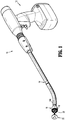
FIG. 1 is a perspective view of a surgical stapling device suitable for use with the plug assemblies of the present disclosure; -
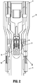
FIG. 2 is a cross-sectional view of a loading unit and a distal portion of an adapter assembly of the surgical stapling device shown inFIG. 1 , including a connector assembly having a plug assembly and a chip assembly; -
FIG. 3 is an enlarged view of the indicated area of detail shown inFIG. 2 ; -
FIG. 4 is a perspective view of a plug assembly according to an embodiment of the present disclosure; -
FIG. 5 is a perspective top view of a tray member, contact members and elongated electrical conductors of the plug assembly shown inFIG. 4 ; -
FIG. 6 is a perspective view of the contact members and elongated electrical conductors of the plug assembly shown inFIG. 4 ; -
FIG. 7 is a perspective cross-sectional view taken along line 7-7 shown inFIG. 5 ; -
FIG. 8 is a perspective top view of the tray member, contact member, and elongated electrical conductors shown inFIG. 4 , and further including a block member; -
FIG. 9 is a perspective top view of plug assembly shown inFIG. 4 , without a seal member; -
FIG. 10 is a perspective bottom view of the plug assembly shown inFIG. 9 ; -
FIG. 11 is a perspective side view of a contact member according to another embodiment of the present disclosure; -
FIG. 12 is a perspective side view of the contact member shown inFIG. 11 , connected to an elongated electric conductor; -
FIG. 13 is a perspective view of a plug assembly according to another embodiment of the present disclosure; -
FIG. 14 is a perspective view of contact members and a flexible cable of the plug assembly shown inFIG. 13 ; -
FIG. 15 is a perspective view of the contact members and flexible cable shown inFIG. 14 received within a tray member; -
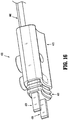
FIG. 16 is a perspective view of a plug assembly according to another embodiment of the present disclosure; -
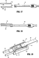
FIG. 17 is a perspective view of contact members and a flexible cable of the plug assembly shown inFIG. 16 , with parts separated; -
FIG. 18 is a perspective view of the contact members and the flexible cable shown inFIG. 17 , connected to one another; -
FIG. 19 is a perspective view of the connected contact members and flexible cable shown inFIG. 18 and received within a tray member; -
FIG. 20 is a perspective top view of plug assembly shown inFIG. 16 , with without a seal member; -
FIG. 21 is a side view of the plug assembly without the seal member shown inFIG. 20 ; and -
FIG. 22 is a perspective bottom view of the plug assembly without the seal member shown inFIG. 20 . - Embodiments of the presently disclosed plug assemblies will now be described in detail with reference to the drawings in which like reference numerals designate identical or corresponding elements in each of the several views. As is common in the art, the term "proximal" refers to that part or component closer to the user or operator, e.g. surgeon or clinician, while the term "distal" refers to that part or component further away from the user.
- Although the plug assemblies of the present disclosure will be shown and described as relates to circular stapling devices, the aspects of the present disclosure may be modified for use with any reusable surgical device utilizing a disposable and/or separable loading unit.
- With reference initially to
FIG. 1 , a surgical stapling instrument suitable for use with a plug assembly of the present disclosure is shown generally ascircular stapler 10. Thecircular stapler 10 includes ahandle assembly 12 and anadapter assembly 14 removably attached to, and extending distally fromhandle assembly 12. A detailed description of an exemplary handle assembly is disclosed in commonly ownedU.S. Pat. App. Pub. No. 2012/0089131 ("the '131 publication"), and a detailed description of an exemplary adapter assembly is disclosed in commonly ownedU.S. Pat. App. Pub. No. 2016/0106406 ("the '406 publication"). The content of each of the '131 and '406 publications is incorporated herein by reference in their entirety. - With additional reference to
FIG. 2 , a reloadassembly 16 is selectively secured to adistal portion 14b ofadapter portion 14. Briefly, the reloadassembly 16 includes acartridge assembly 18 supporting a plurality of staples (not shown). Atrocar 20 extends through the reloadassembly 16 and is configured for releasable connection with ananvil assembly 22. For a detailed description of exemplary reload assemblies, please refer to commonly ownedU.S. Pat. Nos. 9,351,724 9,022,274 - With reference now to
FIGS. 2 and3 , disposed within thedistal portion 14b of theadapter portion 14 of the circular stapler 10 (FIG. 1 ) is aplug assembly 30. Theplug assembly 30 is configured to electrically couple with achip assembly 40 disposed within the reloadassembly 16. The plug andchip assemblies 30, 40 (collectively, connector assembly 50) are configured such that when the reloadassembly 16 is secured to theadapter portion 14 of thecircular stapler 10,connector members plug assembly 20 engagecontact members chip assembly 40. Engagement between theconnector members contact members chip 46 disposed within thechip assembly 40 with a control unit (not shown) disposed within thehandle assembly 12. For a detailed description of an exemplary connector assembly please refer to commonly ownedU.S. Pat. No. 9,833,235 - The harsh environments of disinfecting and sterilization require components that can withstand such methods. These components include pc boards, electronic components such as resistors, diodes, microprocessors, and the like. In many instances, it is necessary to also have connectors that can withstand the harsh environments of common disinfecting and sterilization process such as, for example, high PH auto washers and steam autoclaves.
- With reference now to
FIGS. 4-10 , a plug assembly according to a first embodiment of the present disclosure is shown asplug assembly 100. Theplug assembly 100 includes atray member 110, first andsecond contact members tray member 110, first and second elongatedelectrical conductors second contact members block member 160 received between the first andsecond contact members outer case 170 received about thetray member 110, and aseal member 180 received about the first andsecond contact members distal extension 172 of theouter case 170. - With particular reference to
FIG. 5 , thetray member 110 of theplug assembly 100 includes a substantiallyrectangular body 112 and is formed from a material that can withstand common disinfecting and sterilization processes. In embodiments,tray member 110 is molded using Sabic Noryl HNA055-111S resin. - The
tray member 110 of theplug assembly 100 is configured to support the first andsecond contact members tray member 110 defines first andsecond channels rectangular body 112 for receiving the respective first andsecond contact members rectangular body 112 further defines first andsecond reliefs second channels second cutouts 115, 117 (FIG. 7 ; only one shown) along each of the first andsecond channels recess 119 disposed between the first andsecond channels second reliefs second contact members electrical conductors second cutouts second channels second contact members tray member 110. Therecess 119 is configured to receive theblock member 160. - The
tray member 110 of theplug assembly 100 includes anannular flange 114 extending outwardly from therectangular body 112 defining athroughbore 114a. Theannular flange 114 is configured to facilitate attachment of theplug assembly 100 within and to the adapter assembly 14 (FIG. 2 ). - Turning now to
FIG. 6 , each of the first andsecond contact members elongate body distal portions second contact members second contact members - The
proximal portions second contact members electrical conductors proximal portions extension extensions surface 124a, 134b about which aloop electrical conductors extensions electrical conductors distal portions second contact members second contact members 42, 44 (FIG. 3 ), respectively, of thechip assembly 40. - Still referring to
FIG. 6 , each of the first andsecond contact members plug assembly 100 include afirst tab second tab first tabs second contact members FIG. 7 ; only one shown) in the tray member 110 (FIG. 7 ) and thesecond tabs second contact members FIG. 7 ; only one shown) in the tray member 110 (FIG. 7 ). The first andsecond tabs second contact members second contact members tray member 110. - Although the first and second elongated
electrical conductors electrical conductors electrical conductors - With continued reference to
FIG. 6 , adistal portion electrical conductors loop loop electrical conductors distal portion electrical conductors electrical conductors distal ends electrical conductors loops electrical conductors electrical conductors loops electrical conductors electrical conductors electrical conductors second contact members - During manufacture of the
plug assembly 100, theloops electrical conductors respective extensions second contact members inclined surface extensions respective loops second contact members - Once the
loops electrical conductors second contact members second contact members second channels tray member 110. Theextension second contact members respective loops second reliefs second channels tray member 110. - The configuration of the first and
second reliefs loops electrical conductors second reliefs loops extensions loops electrical conductors electrical conductors - When the first and
second contact members plug assembly 100 are received within the respective first andsecond channels tray member 110, thefirst tabs second contact members FIG. 7 ; only one shown) in thetray member 110 and thesecond tabs second contact members FIG. 7 ; only one shown) in thetray member 110. As noted above, the receipt of the first andsecond tabs second contact members second cutouts second channels second contact members tray member 110. - Turning to
FIG. 8 , after receiving the first andsecond contact members second channels tray member 110, theblock member 160 is received withinrecess 119 of thetray member 110 to further secure the first and second elongatedelectrical conductors second contact members tray member 110. Therecess 119 may be configured such that an interference fit is created between theblock member 160 and thetray member 110. In embodiments, the interference is from 0.005 to 0.0015 inches. Alternatively, theblock member 160 may fit within therecess 119 with a clearance fit. The depth of therecess 119 is such that when theblock member 160 is received within therecess 119, a top surface of theblock member 160 is substantially coplanar with the top surface of thetray member 110. Theblock member 160 is formed from a material that can withstand common disinfecting and sterilization processes. In embodiments, theblock member 160 is molded using Sabic Noryl HNA055-111S resin. - Once the
block member 160 is received within therecess 119 in thetray member 110, material is applied within the first andsecond channels reliefs second channels reliefs - Turning to
FIGS. 9 and 10 , theouter case 170 of theplug assembly 100 is then received over thetray member 110. Theouter case 170 is formed of a material that can withstand common disinfecting and sterilization processes. In embodiments, theouter case 170 is molded using Sabic Noryl HNA055-111S resin. In embodiments, theouter case 170 is formed directly about thetray member 110. For example, theouter case 170 may be molded over the tray member 110 (overmolded). Theouter case 170 includes anextension 172 extending between the first andsecond contact members extension 172 defines a slot oropening 173. Theextension 172 is configured to facilitate the attachment of the seal member 180 (FIG. 4 ) about the first andsecond contact members tray member 110. Theouter case 170 further includes acylindrical projection 174 extending outwardly and disposed adjacent theannular flange 114 of thetray member 110. On a side opposite thecylindrical projection 174, theouter case 170 defines acircular recess 175. - The seal member 180 (
FIG. 4 ) of theplug assembly 100 is fabricated using a low durometer (e.g. rubber properties) resin that can withstand common disinfecting and sterilization processes. In embodiments, theseal member 180 is compression molded using Elastosil LR 3003/60 W A/B-LSR Silicone. However, other suitable materials are possible, including injection molded resins. In embodiments, theseal member 180 is directly formed over the first andsecond contact members tray member 110 using, for example, an overmolding process. Alternatively, theseal member 180 is formed as a separate component that is then received about the first andsecond contact members extension 172 of thetray member 170. - With reference now to
FIGS. 11 and 12 , an alternative embodiment of the first andsecond contact members contact member 220. Thecontact member 220 is configured for electrical connection to the elongated electric conductor 140 (FIG. 12 ) without the need for soldering thecontact member 220 and the elongatedelectric conductor 140 together. Thecontact member 220 is substantially similar to the first andsecond contact members - With continued reference to
FIGS. 11 and 12 , thecontact member 220 includes anelongate body 222 having proximal anddistal portions proximal portion 222a of thecontact member 220 is configured for operable engagement with the elongated electric conductor 140 (FIG. 12 ). More particularly, theproximal portion 222a of thecontact member 220 includes anextension 224. Theextension 224 of thecontact member 220 defines aslot 225 having a distal facing opening. The slot is configured to receive theloop 142 of the elongatedelectric conductor 140. In embodiments, theslot 225 is tapered in the proximal direction to facilitate a friction fit with theloop 142. - Alternatively, after the
loop 142 of the elongatedelectric conductor 140 is received within theslot 225 formed in theextension 224 of thecontact member 220, theextension 224 is bent towards theelongate body 222 of thecontact member 220 to cause the narrowing of theslot 225. This narrowing of theslot 225 squeezes or crimps theloop 142 of the elongatedelectric conductor 140, thereby securing theloop 142 within theslot 225 and ensuring an electrical connection between thecontact member 220 and the elongatedelectric conductor 140. Thecontact member 220 and the elongatedelectric conductor 140 may additionally be soldered together to further ensure the connection between thecontact member 220 and the elongatedelectric conductor 140. - With reference now to
FIGS. 13-15 , another embodiment of a plug assembly according to the present disclosure is shown asplug assembly 300. Theplug assembly 300 is substantially similar to plugassembly 100 described herein, and will only be described in detail to the extent necessary to full disclose the aspects of the present disclosure. - With particular reference to
FIG. 13 , theplug assembly 300 includes atray member 310, first andsecond contact members tray member 310, aflexible cable 340 connected to and extending proximally from the first andsecond contact members tray member 310, a base orblock member 360 received between the first andsecond contact members outer case 370 received about thetray member 310, and aseal member 380 formed about the first andsecond contact members outer case 370. - Turing to
FIG. 14 , each of the first andsecond contact members elongate body proximal portion distal portion flexible cable 340 includes adistal portion 340a having first andsecond extensions first extension 342 of theflexible cable 340 is secured to theproximal portion 322a of thefirst contact member 320 and thesecond extension 344 of theflexible cable 340 is secured to theproximal portion 332a of thesecond contact member 330 in any suitable manner. In embodiments, and as shown, the first andsecond extensions second contact members - Once the
flexible cable 340 is secured to the first andsecond contact members second contact members second channels tray member 310. The first andsecond contact members second channels second tabs FIG. 13 ) is received withinrecess 319 in thetray member 310 and is configured to secure thedistal portion 340a of theflexible cable 340 within thetray member 310. An epoxy or other material may then be injected, or otherwise received, within the first andsecond channels second contact members distal portion 340a of theflexible cable 340 within thetray member 310. - It is envisioned that each of the first and
second extensions flexible cable 340 may include an enlarged portion (not shown) that conforms withreliefs second channels tray member 310. The enlarged portions would assist in preventing the first andsecond extensions flexible cable 340 from being pulled out of thetray member 310, and thereby preventing separation from the respective first andsecond contact members second extensions flexible cable 340, the first andsecond extensions flexible cable 340 may need not be soldered to the respective first andsecond contact members second contact members flexible cable 340. - The
outer case 370 may be secured about thetray member 310 as described above, or in any other suitable manner. Similarly, theseal member 380 may be secured about the first andsecond contact members tray member 310 as described above, or in any other suitable manner. - With reference now to
FIGS. 16-22 , another embodiment of the present disclosure is shown generally asplug assembly 400. Theplug assembly 400 is substantially similar to the plug assemblies described herein and will only be described in detail to the extent necessary to fully disclose the aspects of the present disclosure. - With particular reference to
FIG. 16 , theplug assembly 400 includes atray member 410, first andsecond contact members tray member 410, aflexible cable 440 connected to and extending from the first andsecond contact members outer case 470 received about thetray member 410, and aseal member 480 received about the first andsecond contact members outer case 470. - Turing to
FIG. 17 , each of the first andsecond contact members flexible cable 440 includes adistal portion 340a having first and second contact portions 442, 444. The first contact portion 442 of theflexible cable 340 is secured to the proximal portion 422a of thefirst contact member 420 and the second contact portion 444 of theflexible cable 440 is secured to the proximal portion 432a of thesecond contact member 430 in any suitable manner. In embodiments, and as shown, the first and second contact portions 442, 444 are soldered to the respective first andsecond contact members - Once the
flexible cable 440 is secured to the first andsecond contact members second contact members second channels tray member 410 and thedistal portion 440 of theflexible cable 440 is received within arecess 419 of thetray member 410. A pair ofposts 414 engages thedistal portion 440 of theflexible cable 440, thereby preventing theflexible cable 440 from being pulled from thetray member 410. An epoxy or other material may then be injected, or otherwise received, within the first andsecond channels second contact members distal portion 440a of theflexible cable 440 within thetray member 410. - The
outer case 470 may be secured about thetray member 410 as described above, or in any other suitable manner. Similarly, theseal member 480 may be secured about the first andsecond contact members tray member 310 as described above, or in any other suitable manner. - It will be understood that various modifications may be made to the embodiments disclosed herein. For example, the components of the surgical stapling device can be formed of any material suitable for surgical use and having the required strength characteristics. Therefore, the above description should not be construed as limiting, but merely as exemplifications of preferred embodiments. Those skilled in the art will envision other modifications within the scope and spirit of the claims appended hereto.
- The invention may be described by reference to the following numbered paragraphs:-
- 1. A surgical stapling device comprising:
- a handle assembly;
- an adapter assembly extending from the handle assembly, the adapter assembly including a distal portion configured for operable engagement with a loading unit; and
- a plug assembly disposed within the distal portion of the adapter assembly and configured for electrical connection with a chip assembly in a loading unit, the plug assembly including:
- a tray member;
- first and second contact members received within and extending distally from the tray member, each of the first and second contact members including proximal and distal portions and an extension formed on the proximal portions; and
- first and second elongated electrical conductors in electrical connection with the first and second contact members and extending proximally from the tray member, each of the first and second elongated electrical conductors including proximal and distal portions and a loop formed on the distal portion, the loop of each of the first and second elongated electrical conductors being received about the extension of the respective first and second contact member;
- an outer case formed about the tray member and the proximal portion of the first and second contact members; and
- a seal member received about the first and second contact members adjacent the outer tray.
- 2. The surgical stapling device of paragraph 1, wherein the outer case of the plug assembly is overmolded about the tray member and the proximal portion of the first and second contact members.
- 3. The surgical stapling device of paragraph 1, further including a loading unit, wherein the loading unit includes a chip assembly configured for electrical connection with the plug assembly.
- 4. The surgical stapling device of paragraph 1, wherein the plug assembly further includes a block member received between the first and second contact members.
- 5. The surgical stapling device of paragraph 1, wherein the tray member defines first and second channels and the first and second contact members are received within the respective first and second channels.
- 6. The surgical stapling device of paragraph 5, wherein the first and second elongated electrical conductors are received within the respective first and second channels.
- 7. The surgical stapling device of paragraph 6, wherein the first and second contact members and the first and second elongated electrical conductors are secured within the respective first and second channels with a sealant material.
- 8. The surgical stapling device of
paragraph 7, wherein the sealant material is a thermoset resin. - 9. The surgical stapling device of paragraph 1, wherein the outer case includes a cylindrical projection configured to facilitate connection of the plug assembly with the adapter assembly.
- 10. The surgical stapling device of paragraph 1, wherein the first and second elongated electrical conductors are electrically connected to the handle assembly.
- 11. The surgical stapling device of paragraph 1, wherein the outer case includes a distally extending extension and the seal member is secured to the extension.
- 12. A plug assembly configured for electrical connection with a chip assembly in a loading unit, the plug assembly comprising:
- a tray member;
- first and second contact members received within and extending distally from the tray member, each of the first and second contact members including proximal and distal portions and an extension formed on the proximal portions; and
- first and second elongated electrical conductors in electrical connection with the first and second contact members and extending proximally from the tray member, each of the first and second elongated electrical conductors including proximal and distal portions and a loop formed on the distal portion, the loop of each of the first and second elongated electrical conductors being received about the extension of the respective first and second contact member;
- an outer case formed about the tray member and the proximal portion of the first and second contact members; and
- a seal member received about the first and second contact members adjacent the outer tray.
- 13. The plug assembly of
paragraph 12, wherein the outer case is overmolded about the tray member and the proximal portion of the first and second contact members. - 14. The plug assembly of
paragraph 12, further including a block member received between the first and second contact members. - 15. The plug assembly of
paragraph 12, wherein the tray member defines first and second channels and the first and second contact members are received within the respective first and second channels. - 16. The plug assembly of
paragraph 12, wherein the first and second elongated electrical conductors are received within the respective first and second channels. - 17. The plug assembly of
paragraph 16, wherein the first and second contact members and the first and second elongated electrical conductors are secured within the respective first and second channels with a sealant material. - 18. The plug assembly of paragraph 17, wherein the sealant material is an epoxy.
- 19. The plug assembly of
paragraph 12, wherein the outer case includes a cylindrical projection configured to facilitate connection of the plug assembly with an adapter assembly. - 20. The plug assembly of
paragraph 12, wherein the outer case includes a distally extending extension and the seal member is secured to the extension.
Claims (14)
- A surgical stapling device comprising:a handle assembly;an adapter assembly extending from the handle assembly, the adapter assembly including a distal portion configured for operable engagement with a loading unit; anda plug assembly disposed within the distal portion of the adapter assembly and configured for electrical connection with a chip assembly in a loading unit, the plug assembly including:a tray member;first and second contact members received within and extending distally from the tray member, each of the first and second contact members including proximal and distal portions and an extension formed on the proximal portions; andfirst and second elongated electrical conductors in electrical connection with the first and second contact members and extending proximally from the tray member, each of the first and second elongated electrical conductors including proximal and distal portions and a loop formed on the distal portion, the loop of each of the first and second elongated electrical conductors being received about the extension of the respective first and second contact member;an outer case formed about the tray member and the proximal portion of the first and second contact members; anda seal member received about the first and second contact members adjacent the outer tray.
- The surgical stapling device of claim 1, wherein the outer case of the plug assembly is overmolded about the tray member and the proximal portion of the first and second contact members.
- The surgical stapling device of claim 1 or claim 2 further including a loading unit, wherein the loading unit includes a chip assembly configured for electrical connection with the plug assembly.
- The surgical stapling device of any preceding claim, wherein the plug assembly further includes a block member received between the first and second contact members and/or wherein the tray member defines first and second channels and the first and second contact members are received within the respective first and second channels.
- The surgical stapling device of claim 4, wherein the first and second elongated electrical conductors are received within the respective first and second channels; and/or wherein the first and second contact members and the first and second elongated electrical conductors are secured within the respective first and second channels with a sealant material; preferably wherein the sealant material is a thermoset resin.
- The surgical stapling device of any preceding claim wherein the outer case includes a cylindrical projection configured to facilitate connection of the plug assembly with the adapter assembly and/or wherein the first and second elongated electrical conductors are electrically connected to the handle assembly.
- The surgical stapling device of any preceding claim, wherein the outer case includes a distally extending extension and the seal member is secured to the extension.
- A plug assembly configured for electrical connection with a chip assembly in a loading unit, the plug assembly comprising:a tray member;first and second contact members received within and extending distally from the tray member, each of the first and second contact members including proximal and distal portions and an extension formed on the proximal portions; andfirst and second elongated electrical conductors in electrical connection with the first and second contact members and extending proximally from the tray member, each of the first and second elongated electrical conductors including proximal and distal portions and a loop formed on the distal portion, the loop of each of the first and second elongated electrical conductors being received about the extension of the respective first and second contact member;an outer case formed about the tray member and the proximal portion of the first and second contact members; anda seal member received about the first and second contact members adjacent the outer tray.
- The plug assembly of claim 8, wherein the outer case is overmolded about the tray member and the proximal portion of the first and second contact members.
- The plug assembly of claim 8 or claim 9, further including a block member received between the first and second contact member; and/or wherein the tray member defines first and second channels and the first and second contact members are received within the respective first and second channels.
- The plug assembly of any of claims 8 to 10, wherein the first and second elongated electrical conductors are received within the respective first and second channels.
- The plug assembly of claim 11, wherein the first and second contact members and the first and second elongated electrical conductors are secured within the respective first and second channels with a sealant material; preferably wherein the sealant material is an epoxy.
- The plug assembly of any of claims 8 to 12, wherein the outer case includes a cylindrical projection configured to facilitate connection of the plug assembly with an adapter assembly.
- The plug assembly of any of claims 8 to 12, wherein the outer case includes a distally extending extension and the seal member is secured to the extension.
Applications Claiming Priority (2)
| Application Number | Priority Date | Filing Date | Title |
|---|---|---|---|
| US201862661247P | 2018-04-23 | 2018-04-23 | |
| US16/360,684 US10905416B2 (en) | 2018-04-23 | 2019-03-21 | Over-molded connector for surgical instruments |
Publications (2)
| Publication Number | Publication Date |
|---|---|
| EP3560436A1 true EP3560436A1 (en) | 2019-10-30 |
| EP3560436B1 EP3560436B1 (en) | 2024-04-03 |
Family
ID=66239926
Family Applications (1)
| Application Number | Title | Priority Date | Filing Date |
|---|---|---|---|
| EP19170305.7A Active EP3560436B1 (en) | 2018-04-23 | 2019-04-18 | Over-molded connector for surgical instruments |
Country Status (3)
| Country | Link |
|---|---|
| US (1) | US10905416B2 (en) |
| EP (1) | EP3560436B1 (en) |
| CN (1) | CN110384529B (en) |
Cited By (3)
| Publication number | Priority date | Publication date | Assignee | Title |
|---|---|---|---|---|
| EP3659529A1 (en) * | 2018-11-28 | 2020-06-03 | Covidien LP | Surgical stapler adapter with flexible cable assembly, flexible fingers, and contact clips |
| EP3698728A1 (en) * | 2019-02-22 | 2020-08-26 | Covidien LP | Encapsulated plug assembly for electromechanical surgical devices |
| EP3698727A3 (en) * | 2019-02-22 | 2020-11-25 | Covidien LP | Encapsulated plug assembly for electromechanical surgical devices |
Citations (5)
| Publication number | Priority date | Publication date | Assignee | Title |
|---|---|---|---|---|
| US20120089131A1 (en) | 2007-09-21 | 2012-04-12 | Tyco Healthcare Group Lp | Hand held surgical handle assembly, surgical adapters for use between surgical handle assembly and surgical end effectors, and methods of use |
| US20150048140A1 (en) * | 2013-08-16 | 2015-02-19 | Covidien Lp | Chip assembly for reusable surgical instruments |
| US20160106406A1 (en) | 2014-10-21 | 2016-04-21 | Covidien Lp | Adapter, extension, and connector assemblies for surgical devices |
| US9351724B2 (en) | 2013-01-11 | 2016-05-31 | Covidien Lp | Circular stapling instrument |
| US20160265938A1 (en) * | 2015-03-11 | 2016-09-15 | Covidien Lp | Surgical stapling instruments with linear position assembly |
Family Cites Families (41)
| Publication number | Priority date | Publication date | Assignee | Title |
|---|---|---|---|---|
| US4731058A (en) | 1986-05-22 | 1988-03-15 | Pharmacia Deltec, Inc. | Drug delivery system |
| DE3742830C2 (en) | 1987-12-17 | 1995-11-16 | Teves Gmbh Alfred | Valve block assembly |
| US5391166A (en) | 1991-06-07 | 1995-02-21 | Hemostatic Surgery Corporation | Bi-polar electrosurgical endoscopic instruments having a detachable working end |
| US5971801A (en) | 1996-09-11 | 1999-10-26 | Yazaki Corporation | Service plug having a lever mechanism for positioning circuit terminals and short-circuiting terminals |
| US5954535A (en) | 1997-12-30 | 1999-09-21 | Aerospace Lighting Corporation | Quick release compact fluorescent lamp connector |
| US8229549B2 (en) | 2004-07-09 | 2012-07-24 | Tyco Healthcare Group Lp | Surgical imaging device |
| US8241322B2 (en) | 2005-07-27 | 2012-08-14 | Tyco Healthcare Group Lp | Surgical device |
| US6981941B2 (en) | 1999-06-02 | 2006-01-03 | Power Medical Interventions | Electro-mechanical surgical device |
| US6793652B1 (en) | 1999-06-02 | 2004-09-21 | Power Medical Interventions, Inc. | Electro-mechanical surgical device |
| US7951071B2 (en) | 1999-06-02 | 2011-05-31 | Tyco Healthcare Group Lp | Moisture-detecting shaft for use with an electro-mechanical surgical device |
| EP3158942B1 (en) | 2001-06-22 | 2018-08-08 | Covidien LP | Electro-mechanical surgical device |
| US6988897B2 (en) | 2002-04-29 | 2006-01-24 | Focus Products Group, Llc | Detachable breakaway power supply source |
| US6727477B1 (en) | 2003-03-28 | 2004-04-27 | Lyu Jan Co., Ltd. | Temperature controller |
| US20090090763A1 (en) | 2007-10-05 | 2009-04-09 | Tyco Healthcare Group Lp | Powered surgical stapling device |
| US10105140B2 (en) | 2009-11-20 | 2018-10-23 | Covidien Lp | Surgical console and hand-held surgical device |
| US20050272565A1 (en) | 2004-06-02 | 2005-12-08 | Kuo-Wu Hao | Safety device for treadmills |
| US7959050B2 (en) | 2005-07-26 | 2011-06-14 | Ethicon Endo-Surgery, Inc | Electrically self-powered surgical instrument with manual release |
| US8763879B2 (en) | 2006-01-31 | 2014-07-01 | Ethicon Endo-Surgery, Inc. | Accessing data stored in a memory of surgical instrument |
| US7721931B2 (en) | 2007-01-10 | 2010-05-25 | Ethicon Endo-Surgery, Inc. | Prevention of cartridge reuse in a surgical instrument |
| US7814804B2 (en) | 2007-03-30 | 2010-10-19 | Brunswick Corporation | Methods and apparatus to determine belt condition in exercise equipment |
| US7950560B2 (en) | 2007-04-13 | 2011-05-31 | Tyco Healthcare Group Lp | Powered surgical instrument |
| US20090054208A1 (en) | 2007-08-20 | 2009-02-26 | Shen Yi Wu | Safety device for motorized fitness equipment |
| EP3111854B1 (en) | 2007-09-21 | 2021-01-20 | Covidien LP | Surgical device |
| US20110022032A1 (en) | 2007-10-05 | 2011-01-27 | Tyco Healthcare Group Lp | Battery ejection design for a surgical device |
| US8397971B2 (en) | 2009-02-05 | 2013-03-19 | Ethicon Endo-Surgery, Inc. | Sterilizable surgical instrument |
| JP2013537056A (en) | 2010-09-09 | 2013-09-30 | クイーン マリー アンド ウエストフィールド カレッジ、ユニバーシティ オブ ロンドン | Stoma trephine and anastomosis forming method and forming apparatus |
| US8632525B2 (en) | 2010-09-17 | 2014-01-21 | Ethicon Endo-Surgery, Inc. | Power control arrangements for surgical instruments and batteries |
| US9510895B2 (en) | 2010-11-05 | 2016-12-06 | Ethicon Endo-Surgery, Llc | Surgical instrument with modular shaft and end effector |
| EP4364674A1 (en) | 2011-02-15 | 2024-05-08 | Intuitive Surgical Operations, Inc. | Indicator for knife location in a stapling or vessel sealing instrument |
| DE112011105709T5 (en) | 2011-10-05 | 2014-08-21 | Autonetworks Technologies, Ltd. | Electronic switching unit capable of external connection |
| US8899462B2 (en) | 2011-10-25 | 2014-12-02 | Covidien Lp | Apparatus for endoscopic procedures |
| CN111281457B (en) | 2011-11-15 | 2023-10-20 | 直观外科手术操作公司 | Surgical instrument with retracting blade |
| US9022274B2 (en) | 2012-02-15 | 2015-05-05 | Covidien Lp | Circular stapler with increased lumen diameter |
| US10080563B2 (en) | 2012-06-01 | 2018-09-25 | Covidien Lp | Loading unit detection assembly and surgical device for use therewith |
| US9700310B2 (en) | 2013-08-23 | 2017-07-11 | Ethicon Llc | Firing member retraction devices for powered surgical instruments |
| CN104042288A (en) * | 2013-03-15 | 2014-09-17 | 柯惠Lp公司 | Operation anastomosis device |
| US9750503B2 (en) | 2013-07-11 | 2017-09-05 | Covidien Lp | Methods and devices for performing a surgical anastomosis |
| US10463365B2 (en) * | 2013-10-17 | 2019-11-05 | Covidien Lp | Chip assembly for surgical instruments |
| US9706674B2 (en) | 2014-02-04 | 2017-07-11 | Covidien Lp | Authentication system for reusable surgical instruments |
| US10085744B2 (en) * | 2014-12-08 | 2018-10-02 | Covidien Lp | Loading unit attachment band for surgical stapling instrument |
| US10835255B2 (en) * | 2016-02-10 | 2020-11-17 | Covidien Lp | Adapter assemblies for interconnecting electromechanical handle assemblies and surgical loading units |
-
2019
- 2019-03-21 US US16/360,684 patent/US10905416B2/en active Active
- 2019-04-16 CN CN201910304452.1A patent/CN110384529B/en active Active
- 2019-04-18 EP EP19170305.7A patent/EP3560436B1/en active Active
Patent Citations (6)
| Publication number | Priority date | Publication date | Assignee | Title |
|---|---|---|---|---|
| US20120089131A1 (en) | 2007-09-21 | 2012-04-12 | Tyco Healthcare Group Lp | Hand held surgical handle assembly, surgical adapters for use between surgical handle assembly and surgical end effectors, and methods of use |
| US9351724B2 (en) | 2013-01-11 | 2016-05-31 | Covidien Lp | Circular stapling instrument |
| US20150048140A1 (en) * | 2013-08-16 | 2015-02-19 | Covidien Lp | Chip assembly for reusable surgical instruments |
| US9833235B2 (en) | 2013-08-16 | 2017-12-05 | Covidien Lp | Chip assembly for reusable surgical instruments |
| US20160106406A1 (en) | 2014-10-21 | 2016-04-21 | Covidien Lp | Adapter, extension, and connector assemblies for surgical devices |
| US20160265938A1 (en) * | 2015-03-11 | 2016-09-15 | Covidien Lp | Surgical stapling instruments with linear position assembly |
Cited By (5)
| Publication number | Priority date | Publication date | Assignee | Title |
|---|---|---|---|---|
| EP3659529A1 (en) * | 2018-11-28 | 2020-06-03 | Covidien LP | Surgical stapler adapter with flexible cable assembly, flexible fingers, and contact clips |
| US11369372B2 (en) | 2018-11-28 | 2022-06-28 | Covidien Lp | Surgical stapler adapter with flexible cable assembly, flexible fingers, and contact clips |
| US12029422B2 (en) | 2018-11-28 | 2024-07-09 | Covidien Lp | Surgical stapler adapter with flexible cable assembly, flexible fingers, and contact clips |
| EP3698728A1 (en) * | 2019-02-22 | 2020-08-26 | Covidien LP | Encapsulated plug assembly for electromechanical surgical devices |
| EP3698727A3 (en) * | 2019-02-22 | 2020-11-25 | Covidien LP | Encapsulated plug assembly for electromechanical surgical devices |
Also Published As
| Publication number | Publication date |
|---|---|
| CN110384529B (en) | 2024-04-16 |
| US20190321033A1 (en) | 2019-10-24 |
| CN110384529A (en) | 2019-10-29 |
| EP3560436B1 (en) | 2024-04-03 |
| US10905416B2 (en) | 2021-02-02 |
Similar Documents
| Publication | Publication Date | Title |
|---|---|---|
| EP3560436B1 (en) | Over-molded connector for surgical instruments | |
| US10806445B2 (en) | Chip assembly for reusable surgical instruments | |
| US8147488B2 (en) | Surgical operating apparatus | |
| EP2042112A2 (en) | Surgical operating apparatus | |
| US20190099209A1 (en) | Bipolar electrode saline linked closed loop modulated vacuum system | |
| US10811816B2 (en) | Chip assembly for reusable surgical instruments | |
| AU784537B2 (en) | Hand piece connector | |
| US6986686B2 (en) | Electrical plug for supplying electric power from a power supply to a medical instrument | |
| US20090088743A1 (en) | Surgical operating apparatus | |
| JP7592484B2 (en) | Contact Force Spring with Mechanical Stop | |
| JP2019022756A (en) | Authentication system for reusable surgical instruments | |
| EP2105099A1 (en) | Ultrasonic operating apparatus | |
| JP7022727B2 (en) | Radiofrequency surgical instruments | |
| CN110269656A (en) | The chip assembly of reusable surgical instruments | |
| CN106794041B (en) | Electrical connector for electrosurgical devices | |
| EP2345113A1 (en) | Rotationally adjustable connector assembly | |
| CN106037848A (en) | Staple cartridge for surgical instrument, and surgical instrument | |
| CN105120790A (en) | Packaging material for endoscope treatment system and endoscope system | |
| EP2042113A1 (en) | Surgical operating apparatus | |
| US20120076577A1 (en) | Attachment/detachment mechanism and operation tool system | |
| CN210811269U (en) | Nail bin assembly and medical anastomat comprising same | |
| US20090088668A1 (en) | Surgical operating apparatus | |
| EP3001968A1 (en) | Ingress protection for electrosurgical pencil switch | |
| US20210038288A1 (en) | Endoscopic device | |
| CN115211925B (en) | Endoscopic surgical instrument, and proximal end delivery device and distal end operation device for same |
Legal Events
| Date | Code | Title | Description |
|---|---|---|---|
| PUAI | Public reference made under article 153(3) epc to a published international application that has entered the european phase |
Free format text: ORIGINAL CODE: 0009012 |
|
| STAA | Information on the status of an ep patent application or granted ep patent |
Free format text: STATUS: THE APPLICATION HAS BEEN PUBLISHED |
|
| AK | Designated contracting states |
Kind code of ref document: A1 Designated state(s): AL AT BE BG CH CY CZ DE DK EE ES FI FR GB GR HR HU IE IS IT LI LT LU LV MC MK MT NL NO PL PT RO RS SE SI SK SM TR |
|
| AX | Request for extension of the european patent |
Extension state: BA ME |
|
| STAA | Information on the status of an ep patent application or granted ep patent |
Free format text: STATUS: REQUEST FOR EXAMINATION WAS MADE |
|
| 17P | Request for examination filed |
Effective date: 20200430 |
|
| RBV | Designated contracting states (corrected) |
Designated state(s): AL AT BE BG CH CY CZ DE DK EE ES FI FR GB GR HR HU IE IS IT LI LT LU LV MC MK MT NL NO PL PT RO RS SE SI SK SM TR |
|
| STAA | Information on the status of an ep patent application or granted ep patent |
Free format text: STATUS: EXAMINATION IS IN PROGRESS |
|
| 17Q | First examination report despatched |
Effective date: 20210909 |
|
| GRAP | Despatch of communication of intention to grant a patent |
Free format text: ORIGINAL CODE: EPIDOSNIGR1 |
|
| STAA | Information on the status of an ep patent application or granted ep patent |
Free format text: STATUS: GRANT OF PATENT IS INTENDED |
|
| INTG | Intention to grant announced |
Effective date: 20231019 |
|
| GRAS | Grant fee paid |
Free format text: ORIGINAL CODE: EPIDOSNIGR3 |
|
| GRAA | (expected) grant |
Free format text: ORIGINAL CODE: 0009210 |
|
| STAA | Information on the status of an ep patent application or granted ep patent |
Free format text: STATUS: THE PATENT HAS BEEN GRANTED |
|
| AK | Designated contracting states |
Kind code of ref document: B1 Designated state(s): AL AT BE BG CH CY CZ DE DK EE ES FI FR GB GR HR HU IE IS IT LI LT LU LV MC MK MT NL NO PL PT RO RS SE SI SK SM TR |
|
| REG | Reference to a national code |
Ref country code: GB Ref legal event code: FG4D |
|
| REG | Reference to a national code |
Ref country code: CH Ref legal event code: EP |
|
| REG | Reference to a national code |
Ref country code: IE Ref legal event code: FG4D |
|
| REG | Reference to a national code |
Ref country code: DE Ref legal event code: R096 Ref document number: 602019049303 Country of ref document: DE |
|
| REG | Reference to a national code |
Ref country code: LT Ref legal event code: MG9D |
|
| REG | Reference to a national code |
Ref country code: NL Ref legal event code: MP Effective date: 20240403 |
|
| REG | Reference to a national code |
Ref country code: AT Ref legal event code: MK05 Ref document number: 1671360 Country of ref document: AT Kind code of ref document: T Effective date: 20240403 |
|
| PG25 | Lapsed in a contracting state [announced via postgrant information from national office to epo] |
Ref country code: NL Free format text: LAPSE BECAUSE OF FAILURE TO SUBMIT A TRANSLATION OF THE DESCRIPTION OR TO PAY THE FEE WITHIN THE PRESCRIBED TIME-LIMIT Effective date: 20240403 |
|
| PG25 | Lapsed in a contracting state [announced via postgrant information from national office to epo] |
Ref country code: NL Free format text: LAPSE BECAUSE OF FAILURE TO SUBMIT A TRANSLATION OF THE DESCRIPTION OR TO PAY THE FEE WITHIN THE PRESCRIBED TIME-LIMIT Effective date: 20240403 |
|
| PG25 | Lapsed in a contracting state [announced via postgrant information from national office to epo] |
Ref country code: IS Free format text: LAPSE BECAUSE OF FAILURE TO SUBMIT A TRANSLATION OF THE DESCRIPTION OR TO PAY THE FEE WITHIN THE PRESCRIBED TIME-LIMIT Effective date: 20240803 |
|
| PG25 | Lapsed in a contracting state [announced via postgrant information from national office to epo] |
Ref country code: BG Free format text: LAPSE BECAUSE OF FAILURE TO SUBMIT A TRANSLATION OF THE DESCRIPTION OR TO PAY THE FEE WITHIN THE PRESCRIBED TIME-LIMIT Effective date: 20240403 |
|
| PG25 | Lapsed in a contracting state [announced via postgrant information from national office to epo] |
Ref country code: HR Free format text: LAPSE BECAUSE OF FAILURE TO SUBMIT A TRANSLATION OF THE DESCRIPTION OR TO PAY THE FEE WITHIN THE PRESCRIBED TIME-LIMIT Effective date: 20240403 Ref country code: FI Free format text: LAPSE BECAUSE OF FAILURE TO SUBMIT A TRANSLATION OF THE DESCRIPTION OR TO PAY THE FEE WITHIN THE PRESCRIBED TIME-LIMIT Effective date: 20240403 |
|
| PG25 | Lapsed in a contracting state [announced via postgrant information from national office to epo] |
Ref country code: GR Free format text: LAPSE BECAUSE OF FAILURE TO SUBMIT A TRANSLATION OF THE DESCRIPTION OR TO PAY THE FEE WITHIN THE PRESCRIBED TIME-LIMIT Effective date: 20240704 |
|
| PG25 | Lapsed in a contracting state [announced via postgrant information from national office to epo] |
Ref country code: PT Free format text: LAPSE BECAUSE OF FAILURE TO SUBMIT A TRANSLATION OF THE DESCRIPTION OR TO PAY THE FEE WITHIN THE PRESCRIBED TIME-LIMIT Effective date: 20240805 |
|
| PG25 | Lapsed in a contracting state [announced via postgrant information from national office to epo] |
Ref country code: ES Free format text: LAPSE BECAUSE OF FAILURE TO SUBMIT A TRANSLATION OF THE DESCRIPTION OR TO PAY THE FEE WITHIN THE PRESCRIBED TIME-LIMIT Effective date: 20240403 |
|
| PG25 | Lapsed in a contracting state [announced via postgrant information from national office to epo] |
Ref country code: CZ Free format text: LAPSE BECAUSE OF FAILURE TO SUBMIT A TRANSLATION OF THE DESCRIPTION OR TO PAY THE FEE WITHIN THE PRESCRIBED TIME-LIMIT Effective date: 20240403 |
|
| PG25 | Lapsed in a contracting state [announced via postgrant information from national office to epo] |
Ref country code: AT Free format text: LAPSE BECAUSE OF FAILURE TO SUBMIT A TRANSLATION OF THE DESCRIPTION OR TO PAY THE FEE WITHIN THE PRESCRIBED TIME-LIMIT Effective date: 20240403 |
|
| PG25 | Lapsed in a contracting state [announced via postgrant information from national office to epo] |
Ref country code: PL Free format text: LAPSE BECAUSE OF FAILURE TO SUBMIT A TRANSLATION OF THE DESCRIPTION OR TO PAY THE FEE WITHIN THE PRESCRIBED TIME-LIMIT Effective date: 20240403 |
|
| PG25 | Lapsed in a contracting state [announced via postgrant information from national office to epo] |
Ref country code: LV Free format text: LAPSE BECAUSE OF FAILURE TO SUBMIT A TRANSLATION OF THE DESCRIPTION OR TO PAY THE FEE WITHIN THE PRESCRIBED TIME-LIMIT Effective date: 20240403 |
|
| PG25 | Lapsed in a contracting state [announced via postgrant information from national office to epo] |
Ref country code: PT Free format text: LAPSE BECAUSE OF FAILURE TO SUBMIT A TRANSLATION OF THE DESCRIPTION OR TO PAY THE FEE WITHIN THE PRESCRIBED TIME-LIMIT Effective date: 20240805 Ref country code: PL Free format text: LAPSE BECAUSE OF FAILURE TO SUBMIT A TRANSLATION OF THE DESCRIPTION OR TO PAY THE FEE WITHIN THE PRESCRIBED TIME-LIMIT Effective date: 20240403 Ref country code: NO Free format text: LAPSE BECAUSE OF FAILURE TO SUBMIT A TRANSLATION OF THE DESCRIPTION OR TO PAY THE FEE WITHIN THE PRESCRIBED TIME-LIMIT Effective date: 20240703 Ref country code: LV Free format text: LAPSE BECAUSE OF FAILURE TO SUBMIT A TRANSLATION OF THE DESCRIPTION OR TO PAY THE FEE WITHIN THE PRESCRIBED TIME-LIMIT Effective date: 20240403 Ref country code: IS Free format text: LAPSE BECAUSE OF FAILURE TO SUBMIT A TRANSLATION OF THE DESCRIPTION OR TO PAY THE FEE WITHIN THE PRESCRIBED TIME-LIMIT Effective date: 20240803 Ref country code: HR Free format text: LAPSE BECAUSE OF FAILURE TO SUBMIT A TRANSLATION OF THE DESCRIPTION OR TO PAY THE FEE WITHIN THE PRESCRIBED TIME-LIMIT Effective date: 20240403 Ref country code: GR Free format text: LAPSE BECAUSE OF FAILURE TO SUBMIT A TRANSLATION OF THE DESCRIPTION OR TO PAY THE FEE WITHIN THE PRESCRIBED TIME-LIMIT Effective date: 20240704 Ref country code: FI Free format text: LAPSE BECAUSE OF FAILURE TO SUBMIT A TRANSLATION OF THE DESCRIPTION OR TO PAY THE FEE WITHIN THE PRESCRIBED TIME-LIMIT Effective date: 20240403 Ref country code: ES Free format text: LAPSE BECAUSE OF FAILURE TO SUBMIT A TRANSLATION OF THE DESCRIPTION OR TO PAY THE FEE WITHIN THE PRESCRIBED TIME-LIMIT Effective date: 20240403 Ref country code: CZ Free format text: LAPSE BECAUSE OF FAILURE TO SUBMIT A TRANSLATION OF THE DESCRIPTION OR TO PAY THE FEE WITHIN THE PRESCRIBED TIME-LIMIT Effective date: 20240403 Ref country code: BG Free format text: LAPSE BECAUSE OF FAILURE TO SUBMIT A TRANSLATION OF THE DESCRIPTION OR TO PAY THE FEE WITHIN THE PRESCRIBED TIME-LIMIT Effective date: 20240403 Ref country code: AT Free format text: LAPSE BECAUSE OF FAILURE TO SUBMIT A TRANSLATION OF THE DESCRIPTION OR TO PAY THE FEE WITHIN THE PRESCRIBED TIME-LIMIT Effective date: 20240403 Ref country code: RS Free format text: LAPSE BECAUSE OF FAILURE TO SUBMIT A TRANSLATION OF THE DESCRIPTION OR TO PAY THE FEE WITHIN THE PRESCRIBED TIME-LIMIT Effective date: 20240703 |
|
| REG | Reference to a national code |
Ref country code: CH Ref legal event code: PL |
|
| PG25 | Lapsed in a contracting state [announced via postgrant information from national office to epo] |
Ref country code: LU Free format text: LAPSE BECAUSE OF NON-PAYMENT OF DUE FEES Effective date: 20240418 |
|
| REG | Reference to a national code |
Ref country code: BE Ref legal event code: MM Effective date: 20240430 |
|
| PG25 | Lapsed in a contracting state [announced via postgrant information from national office to epo] |
Ref country code: LU Free format text: LAPSE BECAUSE OF NON-PAYMENT OF DUE FEES Effective date: 20240418 |
|
| REG | Reference to a national code |
Ref country code: DE Ref legal event code: R097 Ref document number: 602019049303 Country of ref document: DE |
|
| PG25 | Lapsed in a contracting state [announced via postgrant information from national office to epo] |
Ref country code: DK Free format text: LAPSE BECAUSE OF FAILURE TO SUBMIT A TRANSLATION OF THE DESCRIPTION OR TO PAY THE FEE WITHIN THE PRESCRIBED TIME-LIMIT Effective date: 20240403 |
|
| PG25 | Lapsed in a contracting state [announced via postgrant information from national office to epo] |
Ref country code: BE Free format text: LAPSE BECAUSE OF NON-PAYMENT OF DUE FEES Effective date: 20240430 |
|
| PG25 | Lapsed in a contracting state [announced via postgrant information from national office to epo] |
Ref country code: EE Free format text: LAPSE BECAUSE OF FAILURE TO SUBMIT A TRANSLATION OF THE DESCRIPTION OR TO PAY THE FEE WITHIN THE PRESCRIBED TIME-LIMIT Effective date: 20240403 |
|
| PG25 | Lapsed in a contracting state [announced via postgrant information from national office to epo] |
Ref country code: RO Free format text: LAPSE BECAUSE OF FAILURE TO SUBMIT A TRANSLATION OF THE DESCRIPTION OR TO PAY THE FEE WITHIN THE PRESCRIBED TIME-LIMIT Effective date: 20240403 Ref country code: SK Free format text: LAPSE BECAUSE OF FAILURE TO SUBMIT A TRANSLATION OF THE DESCRIPTION OR TO PAY THE FEE WITHIN THE PRESCRIBED TIME-LIMIT Effective date: 20240403 |
|
| PG25 | Lapsed in a contracting state [announced via postgrant information from national office to epo] |
Ref country code: SM Free format text: LAPSE BECAUSE OF FAILURE TO SUBMIT A TRANSLATION OF THE DESCRIPTION OR TO PAY THE FEE WITHIN THE PRESCRIBED TIME-LIMIT Effective date: 20240403 |
|
| PG25 | Lapsed in a contracting state [announced via postgrant information from national office to epo] |
Ref country code: SM Free format text: LAPSE BECAUSE OF FAILURE TO SUBMIT A TRANSLATION OF THE DESCRIPTION OR TO PAY THE FEE WITHIN THE PRESCRIBED TIME-LIMIT Effective date: 20240403 Ref country code: SK Free format text: LAPSE BECAUSE OF FAILURE TO SUBMIT A TRANSLATION OF THE DESCRIPTION OR TO PAY THE FEE WITHIN THE PRESCRIBED TIME-LIMIT Effective date: 20240403 Ref country code: RO Free format text: LAPSE BECAUSE OF FAILURE TO SUBMIT A TRANSLATION OF THE DESCRIPTION OR TO PAY THE FEE WITHIN THE PRESCRIBED TIME-LIMIT Effective date: 20240403 Ref country code: EE Free format text: LAPSE BECAUSE OF FAILURE TO SUBMIT A TRANSLATION OF THE DESCRIPTION OR TO PAY THE FEE WITHIN THE PRESCRIBED TIME-LIMIT Effective date: 20240403 Ref country code: DK Free format text: LAPSE BECAUSE OF FAILURE TO SUBMIT A TRANSLATION OF THE DESCRIPTION OR TO PAY THE FEE WITHIN THE PRESCRIBED TIME-LIMIT Effective date: 20240403 Ref country code: BE Free format text: LAPSE BECAUSE OF NON-PAYMENT OF DUE FEES Effective date: 20240430 Ref country code: CH Free format text: LAPSE BECAUSE OF NON-PAYMENT OF DUE FEES Effective date: 20240430 Ref country code: MC Free format text: LAPSE BECAUSE OF FAILURE TO SUBMIT A TRANSLATION OF THE DESCRIPTION OR TO PAY THE FEE WITHIN THE PRESCRIBED TIME-LIMIT Effective date: 20240403 |
|
| PLBE | No opposition filed within time limit |
Free format text: ORIGINAL CODE: 0009261 |
|
| STAA | Information on the status of an ep patent application or granted ep patent |
Free format text: STATUS: NO OPPOSITION FILED WITHIN TIME LIMIT |
|
| 26N | No opposition filed |
Effective date: 20250106 |
|
| GBPC | Gb: european patent ceased through non-payment of renewal fee |
Effective date: 20240703 |
|
| PG25 | Lapsed in a contracting state [announced via postgrant information from national office to epo] |
Ref country code: IE Free format text: LAPSE BECAUSE OF NON-PAYMENT OF DUE FEES Effective date: 20240418 |
|
| PG25 | Lapsed in a contracting state [announced via postgrant information from national office to epo] |
Ref country code: SI Free format text: LAPSE BECAUSE OF FAILURE TO SUBMIT A TRANSLATION OF THE DESCRIPTION OR TO PAY THE FEE WITHIN THE PRESCRIBED TIME-LIMIT Effective date: 20240403 |
|
| PG25 | Lapsed in a contracting state [announced via postgrant information from national office to epo] |
Ref country code: GB Free format text: LAPSE BECAUSE OF NON-PAYMENT OF DUE FEES Effective date: 20240703 |
|
| PGFP | Annual fee paid to national office [announced via postgrant information from national office to epo] |
Ref country code: DE Payment date: 20250319 Year of fee payment: 7 |
|
| PG25 | Lapsed in a contracting state [announced via postgrant information from national office to epo] |
Ref country code: CY Free format text: LAPSE BECAUSE OF FAILURE TO SUBMIT A TRANSLATION OF THE DESCRIPTION OR TO PAY THE FEE WITHIN THE PRESCRIBED TIME-LIMIT; INVALID AB INITIO Effective date: 20190418 |
|
| PG25 | Lapsed in a contracting state [announced via postgrant information from national office to epo] |
Ref country code: HU Free format text: LAPSE BECAUSE OF FAILURE TO SUBMIT A TRANSLATION OF THE DESCRIPTION OR TO PAY THE FEE WITHIN THE PRESCRIBED TIME-LIMIT; INVALID AB INITIO Effective date: 20190418 |
|
| PG25 | Lapsed in a contracting state [announced via postgrant information from national office to epo] |
Ref country code: SE Free format text: LAPSE BECAUSE OF FAILURE TO SUBMIT A TRANSLATION OF THE DESCRIPTION OR TO PAY THE FEE WITHIN THE PRESCRIBED TIME-LIMIT Effective date: 20240403 |
|
| PG25 | Lapsed in a contracting state [announced via postgrant information from national office to epo] |
Ref country code: IT Free format text: LAPSE BECAUSE OF FAILURE TO SUBMIT A TRANSLATION OF THE DESCRIPTION OR TO PAY THE FEE WITHIN THE PRESCRIBED TIME-LIMIT Effective date: 20240403 |
|
| PGFP | Annual fee paid to national office [announced via postgrant information from national office to epo] |
Ref country code: FR Payment date: 20260320 Year of fee payment: 8 |