EP3560424A1 - Multimodality 2d to 3d imaging navigation - Google Patents
Multimodality 2d to 3d imaging navigation Download PDFInfo
- Publication number
- EP3560424A1 EP3560424A1 EP19170954.2A EP19170954A EP3560424A1 EP 3560424 A1 EP3560424 A1 EP 3560424A1 EP 19170954 A EP19170954 A EP 19170954A EP 3560424 A1 EP3560424 A1 EP 3560424A1
- Authority
- EP
- European Patent Office
- Prior art keywords
- image
- synthetic
- volume
- dbt
- acquisition
- Prior art date
- Legal status (The legal status is an assumption and is not a legal conclusion. Google has not performed a legal analysis and makes no representation as to the accuracy of the status listed.)
- Granted
Links
Images



Classifications
-
- G—PHYSICS
- G06—COMPUTING OR CALCULATING; COUNTING
- G06T—IMAGE DATA PROCESSING OR GENERATION, IN GENERAL
- G06T7/00—Image analysis
- G06T7/0002—Inspection of images, e.g. flaw detection
- G06T7/0012—Biomedical image inspection
-
- A—HUMAN NECESSITIES
- A61—MEDICAL OR VETERINARY SCIENCE; HYGIENE
- A61B—DIAGNOSIS; SURGERY; IDENTIFICATION
- A61B6/00—Apparatus or devices for radiation diagnosis; Apparatus or devices for radiation diagnosis combined with radiation therapy equipment
- A61B6/02—Arrangements for diagnosis sequentially in different planes; Stereoscopic radiation diagnosis
- A61B6/025—Tomosynthesis
-
- A—HUMAN NECESSITIES
- A61—MEDICAL OR VETERINARY SCIENCE; HYGIENE
- A61B—DIAGNOSIS; SURGERY; IDENTIFICATION
- A61B34/00—Computer-aided surgery; Manipulators or robots specially adapted for use in surgery
- A61B34/20—Surgical navigation systems; Devices for tracking or guiding surgical instruments, e.g. for frameless stereotaxis
-
- A—HUMAN NECESSITIES
- A61—MEDICAL OR VETERINARY SCIENCE; HYGIENE
- A61B—DIAGNOSIS; SURGERY; IDENTIFICATION
- A61B6/00—Apparatus or devices for radiation diagnosis; Apparatus or devices for radiation diagnosis combined with radiation therapy equipment
- A61B6/46—Arrangements for interfacing with the operator or the patient
- A61B6/461—Displaying means of special interest
- A61B6/463—Displaying means of special interest characterised by displaying multiple images or images and diagnostic data on one display
-
- A—HUMAN NECESSITIES
- A61—MEDICAL OR VETERINARY SCIENCE; HYGIENE
- A61B—DIAGNOSIS; SURGERY; IDENTIFICATION
- A61B6/00—Apparatus or devices for radiation diagnosis; Apparatus or devices for radiation diagnosis combined with radiation therapy equipment
- A61B6/46—Arrangements for interfacing with the operator or the patient
- A61B6/467—Arrangements for interfacing with the operator or the patient characterised by special input means
- A61B6/469—Arrangements for interfacing with the operator or the patient characterised by special input means for selecting a region of interest [ROI]
-
- A—HUMAN NECESSITIES
- A61—MEDICAL OR VETERINARY SCIENCE; HYGIENE
- A61B—DIAGNOSIS; SURGERY; IDENTIFICATION
- A61B6/00—Apparatus or devices for radiation diagnosis; Apparatus or devices for radiation diagnosis combined with radiation therapy equipment
- A61B6/48—Diagnostic techniques
- A61B6/481—Diagnostic techniques involving the use of contrast agents
-
- A—HUMAN NECESSITIES
- A61—MEDICAL OR VETERINARY SCIENCE; HYGIENE
- A61B—DIAGNOSIS; SURGERY; IDENTIFICATION
- A61B6/00—Apparatus or devices for radiation diagnosis; Apparatus or devices for radiation diagnosis combined with radiation therapy equipment
- A61B6/50—Apparatus or devices for radiation diagnosis; Apparatus or devices for radiation diagnosis combined with radiation therapy equipment specially adapted for specific body parts; specially adapted for specific clinical applications
- A61B6/502—Apparatus or devices for radiation diagnosis; Apparatus or devices for radiation diagnosis combined with radiation therapy equipment specially adapted for specific body parts; specially adapted for specific clinical applications for diagnosis of breast, i.e. mammography
-
- A—HUMAN NECESSITIES
- A61—MEDICAL OR VETERINARY SCIENCE; HYGIENE
- A61B—DIAGNOSIS; SURGERY; IDENTIFICATION
- A61B6/00—Apparatus or devices for radiation diagnosis; Apparatus or devices for radiation diagnosis combined with radiation therapy equipment
- A61B6/52—Devices using data or image processing specially adapted for radiation diagnosis
- A61B6/5211—Devices using data or image processing specially adapted for radiation diagnosis involving processing of medical diagnostic data
- A61B6/5223—Devices using data or image processing specially adapted for radiation diagnosis involving processing of medical diagnostic data generating planar views from image data, e.g. extracting a coronal view from a 3D image
-
- A—HUMAN NECESSITIES
- A61—MEDICAL OR VETERINARY SCIENCE; HYGIENE
- A61B—DIAGNOSIS; SURGERY; IDENTIFICATION
- A61B6/00—Apparatus or devices for radiation diagnosis; Apparatus or devices for radiation diagnosis combined with radiation therapy equipment
- A61B6/52—Devices using data or image processing specially adapted for radiation diagnosis
- A61B6/5211—Devices using data or image processing specially adapted for radiation diagnosis involving processing of medical diagnostic data
- A61B6/5229—Devices using data or image processing specially adapted for radiation diagnosis involving processing of medical diagnostic data combining image data of a patient, e.g. combining a functional image with an anatomical image
- A61B6/5235—Devices using data or image processing specially adapted for radiation diagnosis involving processing of medical diagnostic data combining image data of a patient, e.g. combining a functional image with an anatomical image combining images from the same or different ionising radiation imaging techniques, e.g. PET and CT
-
- A—HUMAN NECESSITIES
- A61—MEDICAL OR VETERINARY SCIENCE; HYGIENE
- A61B—DIAGNOSIS; SURGERY; IDENTIFICATION
- A61B6/00—Apparatus or devices for radiation diagnosis; Apparatus or devices for radiation diagnosis combined with radiation therapy equipment
- A61B6/52—Devices using data or image processing specially adapted for radiation diagnosis
- A61B6/5211—Devices using data or image processing specially adapted for radiation diagnosis involving processing of medical diagnostic data
- A61B6/5229—Devices using data or image processing specially adapted for radiation diagnosis involving processing of medical diagnostic data combining image data of a patient, e.g. combining a functional image with an anatomical image
- A61B6/5247—Devices using data or image processing specially adapted for radiation diagnosis involving processing of medical diagnostic data combining image data of a patient, e.g. combining a functional image with an anatomical image combining images from an ionising-radiation diagnostic technique and a non-ionising radiation diagnostic technique, e.g. X-ray and ultrasound
-
- A—HUMAN NECESSITIES
- A61—MEDICAL OR VETERINARY SCIENCE; HYGIENE
- A61B—DIAGNOSIS; SURGERY; IDENTIFICATION
- A61B8/00—Diagnosis using ultrasonic, sonic or infrasonic waves
- A61B8/08—Clinical applications
- A61B8/0825—Clinical applications for diagnosis of the breast, e.g. mammography
-
- A—HUMAN NECESSITIES
- A61—MEDICAL OR VETERINARY SCIENCE; HYGIENE
- A61B—DIAGNOSIS; SURGERY; IDENTIFICATION
- A61B8/00—Diagnosis using ultrasonic, sonic or infrasonic waves
- A61B8/08—Clinical applications
- A61B8/0833—Clinical applications involving detecting or locating foreign bodies or organic structures
- A61B8/085—Clinical applications involving detecting or locating foreign bodies or organic structures for locating body or organic structures, e.g. tumours, calculi, blood vessels, nodules
-
- A—HUMAN NECESSITIES
- A61—MEDICAL OR VETERINARY SCIENCE; HYGIENE
- A61B—DIAGNOSIS; SURGERY; IDENTIFICATION
- A61B8/00—Diagnosis using ultrasonic, sonic or infrasonic waves
- A61B8/42—Details of probe positioning or probe attachment to the patient
- A61B8/4209—Details of probe positioning or probe attachment to the patient by using holders, e.g. positioning frames
- A61B8/4218—Details of probe positioning or probe attachment to the patient by using holders, e.g. positioning frames characterised by articulated arms
-
- A—HUMAN NECESSITIES
- A61—MEDICAL OR VETERINARY SCIENCE; HYGIENE
- A61B—DIAGNOSIS; SURGERY; IDENTIFICATION
- A61B8/00—Diagnosis using ultrasonic, sonic or infrasonic waves
- A61B8/52—Devices using data or image processing specially adapted for diagnosis using ultrasonic, sonic or infrasonic waves
- A61B8/5207—Devices using data or image processing specially adapted for diagnosis using ultrasonic, sonic or infrasonic waves involving processing of raw data to produce diagnostic data, e.g. for generating an image
-
- A—HUMAN NECESSITIES
- A61—MEDICAL OR VETERINARY SCIENCE; HYGIENE
- A61B—DIAGNOSIS; SURGERY; IDENTIFICATION
- A61B8/00—Diagnosis using ultrasonic, sonic or infrasonic waves
- A61B8/54—Control of the diagnostic device
-
- G—PHYSICS
- G06—COMPUTING OR CALCULATING; COUNTING
- G06T—IMAGE DATA PROCESSING OR GENERATION, IN GENERAL
- G06T12/00—Tomographic reconstruction from projections
-
- G—PHYSICS
- G06—COMPUTING OR CALCULATING; COUNTING
- G06T—IMAGE DATA PROCESSING OR GENERATION, IN GENERAL
- G06T15/00—Three-dimensional [3D] image rendering
- G06T15/08—Volume rendering
-
- A—HUMAN NECESSITIES
- A61—MEDICAL OR VETERINARY SCIENCE; HYGIENE
- A61B—DIAGNOSIS; SURGERY; IDENTIFICATION
- A61B34/00—Computer-aided surgery; Manipulators or robots specially adapted for use in surgery
- A61B34/20—Surgical navigation systems; Devices for tracking or guiding surgical instruments, e.g. for frameless stereotaxis
- A61B2034/2046—Tracking techniques
- A61B2034/2063—Acoustic tracking systems, e.g. using ultrasound
-
- A—HUMAN NECESSITIES
- A61—MEDICAL OR VETERINARY SCIENCE; HYGIENE
- A61B—DIAGNOSIS; SURGERY; IDENTIFICATION
- A61B34/00—Computer-aided surgery; Manipulators or robots specially adapted for use in surgery
- A61B34/20—Surgical navigation systems; Devices for tracking or guiding surgical instruments, e.g. for frameless stereotaxis
- A61B2034/2046—Tracking techniques
- A61B2034/2065—Tracking using image or pattern recognition
-
- A—HUMAN NECESSITIES
- A61—MEDICAL OR VETERINARY SCIENCE; HYGIENE
- A61B—DIAGNOSIS; SURGERY; IDENTIFICATION
- A61B8/00—Diagnosis using ultrasonic, sonic or infrasonic waves
- A61B8/42—Details of probe positioning or probe attachment to the patient
- A61B8/4272—Details of probe positioning or probe attachment to the patient involving the acoustic interface between the transducer and the tissue
- A61B8/4281—Details of probe positioning or probe attachment to the patient involving the acoustic interface between the transducer and the tissue characterised by sound-transmitting media or devices for coupling the transducer to the tissue
-
- G—PHYSICS
- G06—COMPUTING OR CALCULATING; COUNTING
- G06T—IMAGE DATA PROCESSING OR GENERATION, IN GENERAL
- G06T2200/00—Indexing scheme for image data processing or generation, in general
- G06T2200/04—Indexing scheme for image data processing or generation, in general involving 3D image data
-
- G—PHYSICS
- G06—COMPUTING OR CALCULATING; COUNTING
- G06T—IMAGE DATA PROCESSING OR GENERATION, IN GENERAL
- G06T2207/00—Indexing scheme for image analysis or image enhancement
- G06T2207/10—Image acquisition modality
- G06T2207/10072—Tomographic images
- G06T2207/10081—Computed x-ray tomography [CT]
-
- G—PHYSICS
- G06—COMPUTING OR CALCULATING; COUNTING
- G06T—IMAGE DATA PROCESSING OR GENERATION, IN GENERAL
- G06T2207/00—Indexing scheme for image analysis or image enhancement
- G06T2207/10—Image acquisition modality
- G06T2207/10072—Tomographic images
- G06T2207/10084—Hybrid tomography; Concurrent acquisition with multiple different tomographic modalities
-
- G—PHYSICS
- G06—COMPUTING OR CALCULATING; COUNTING
- G06T—IMAGE DATA PROCESSING OR GENERATION, IN GENERAL
- G06T2207/00—Indexing scheme for image analysis or image enhancement
- G06T2207/10—Image acquisition modality
- G06T2207/10072—Tomographic images
- G06T2207/10088—Magnetic resonance imaging [MRI]
-
- G—PHYSICS
- G06—COMPUTING OR CALCULATING; COUNTING
- G06T—IMAGE DATA PROCESSING OR GENERATION, IN GENERAL
- G06T2207/00—Indexing scheme for image analysis or image enhancement
- G06T2207/10—Image acquisition modality
- G06T2207/10072—Tomographic images
- G06T2207/10112—Digital tomosynthesis [DTS]
-
- G—PHYSICS
- G06—COMPUTING OR CALCULATING; COUNTING
- G06T—IMAGE DATA PROCESSING OR GENERATION, IN GENERAL
- G06T2207/00—Indexing scheme for image analysis or image enhancement
- G06T2207/30—Subject of image; Context of image processing
- G06T2207/30004—Biomedical image processing
- G06T2207/30068—Mammography; Breast
Definitions
- the ultrasound transducer may be movable in a plurality of lateral directions (e.g., the actuator 234 may include a plurality of linear actuators or otherwise be configured to articulate the ultrasound transducer 232 in a plurality of directions).
- the actuator 234 may be configured to move the ultrasound transducer in a raster pattern sized and configured to cover a region of interest.
- the ultrasound transducer 232 may be removably mounted to a paddle or plate, and physically removed from the paddle or plate during X-ray scanning.
Landscapes
- Health & Medical Sciences (AREA)
- Life Sciences & Earth Sciences (AREA)
- Engineering & Computer Science (AREA)
- Medical Informatics (AREA)
- Physics & Mathematics (AREA)
- General Health & Medical Sciences (AREA)
- Nuclear Medicine, Radiotherapy & Molecular Imaging (AREA)
- Surgery (AREA)
- Radiology & Medical Imaging (AREA)
- Heart & Thoracic Surgery (AREA)
- Molecular Biology (AREA)
- Public Health (AREA)
- Veterinary Medicine (AREA)
- Biomedical Technology (AREA)
- Animal Behavior & Ethology (AREA)
- Biophysics (AREA)
- Pathology (AREA)
- Optics & Photonics (AREA)
- High Energy & Nuclear Physics (AREA)
- Computer Vision & Pattern Recognition (AREA)
- General Physics & Mathematics (AREA)
- Theoretical Computer Science (AREA)
- Human Computer Interaction (AREA)
- Quality & Reliability (AREA)
- Computer Graphics (AREA)
- Robotics (AREA)
- Vascular Medicine (AREA)
- Dentistry (AREA)
- Oral & Maxillofacial Surgery (AREA)
- Ultra Sonic Daignosis Equipment (AREA)
- Apparatus For Radiation Diagnosis (AREA)
Abstract
Description
- The present disclosure relates to the field of combined 2D and 3D imaging and to a method and system for processing 2D and 3D imaging data for improving navigation through the imaging data.
- X-ray imaging systems have become a valuable tool in medical applications such as for the diagnosis of many diseases. As standard screening for breast cancer mammography 2-dimensional (2D) x-ray images are taken across the entire breast tissue. These known 2D mammograms are limited by tissue superimposition. That is to say, lesions may be masked by the tissue above or underneath, or normal structures may mimic a lesion. In order to minimize limitations of standard 2D-mammography caused by tissue superimposition, digital breast tomosynthesis using digital receptors has been developed.
- Current tomosynthesis systems employ at least one x-ray tube, which is moved, e.g., in an arc, above a stationary detector. In digital breast tomosynthesis (DBT) the volume information of an object of interest can be derived from a series of images, known as projection images or projections, which are taken at various angles by means of one or more x-ray sources. Objects of different heights in a breast display differently in the different projections. From the 2D projection images 3D volumes can be generated for review. The generated 3D volume portions offer advantages to overcome the limitations associated with tissue superimposition.
- However, if a potential lesion or other abnormality is identified on a 2D or 3D tomosynthesis X-ray image, a follow-up visit is scheduled for an ultrasound exam or MRI of the breast to confirm or check the initial diagnosis based on the X-ray image. Such rescheduling typically involves a delay of days or even weeks between exams. This amount of time can lead to patient anxiety and concern between the examinations. Further, because the exams are conducted at separate visits, and also because upright positioning and compression is typically used for mammographic X-ray exams and supine positioning is used for ultrasound or prone for MRI, it is very difficult to co-register the X-ray image and ultrasound image such that the radiologist or other practitioner can view the same areas imaged using the different modalities. Present techniques for performing ultrasound examinations of the breast have additional drawbacks, such as the time associated with such examinations.
- In addition if the patient is found to have dense breasts she may be referred for whole breast ultrasound screening to be performed on the same visit or subsequent visit. The ultrasound imaging can be performed either by hand by an experienced sonographer technologist and a standard ultrasound imaging system or with a specially designed automated breast ultrasound system (ABUS).
- To address this issue with regard to the need for tomosynthesis and 3D ultrasound imaging of the breast, combined imaging systems have been developed such as that disclosed in US Patent Application Publication No.
US2014/0135623 entitled SYSTEMS AND METHODS FOR X-RAY AND ULTRASOUND IMAGING, the entirety of which is expressly incorporated herein by reference for all purposes. In these systems, an imaging system including X-ray and ultrasound modalities can be articulated to position and/or compress an object, such as a portion of a human anatomy (e.g., a breast) to perform an X-ray scan or exam. Using information obtained via the X-ray scan or exam, one or more portions of interest of the object may be identified for further analysis using ultrasound imaging on the same system. - While combined imaging systems of this type facilitate the obtaining and review of combined 2D and 3D images of the tissue, in order to effectively review the images, the images are displayed separately to the radiologist or other practitioner. During review of the images, the radiologist will typically separately view the 2D mammography and 3D ultrasound images for one patient, and search for suspicious areas in both images. Radiologists very often need to verify on mammography images suspicious areas of regions of interest (ROI's) found in ultrasound and vice versa. Because the patient or breast positioning used in acquiring mammograms and 3D ultrasound are often very different, it is not immediately obvious to the radiologist what location in an image of one modality corresponds to an ROI found in another modality. In practice, the manual method practiced by radiologists is quite tedious and prone to error. For example, the radiologist will measure the distance of an ROI from the nipple and estimate the clock face position of the ROI on the mammogram and then find the corresponding ROI on the 3D breast ultrasound images based on that measurement.
- In order to address this issue and attempt to speed up the workflow of the review of the combined images, one solution that has been developed is disclosed in US Patent Application Publication No.
US2014/0082542 entitled VIEWING AND CORRELATING BETWEEN BREAST ULTRASOUND AND MAMMOGRAM OR BREAST TOMOSYNTHESIS IMAGES, the entirety of which is expressly incorporated herein by reference for all purposes. In this solution, mammography images, that is, images taken along the mediolateral-oblique (MLO) and cranial-caudal (CC) planes, and a 3D ultrasound image are each obtained of the tissue being imaged. In response to the selection of an identified ROI on one of the mammogram images or ultrasound images by the user of the system, the system automatically calculates the coordinates of the selected ROI within the other modality image(s) and provides navigation aids on those image(s) to assist the user in determining the location of the ROI on the other of the images. - However, variations in the images obtained in the mammography and ultrasound modalities, along with any variations in the form or state of the tissue being imaged, such as the upright compression of the breast during the mammography imaging versus the supine compressed tissue in ultrasound imaging, creates significant correlation issues between the locations of the selected ROIs within the mammography images and within the ultrasound images. Further the separate review of the image data of each modality greatly slows down the review and workflow. This, in turn, presents significant problems with the proper determination of the exact location of the ROI in either image, particularly with regard to small ROIs and/or when the images are obtained at different times and with separate compressions, thereby increasing the time required to properly analyze the images and increasing the number of false positive screening callbacks and eventually biopsies.
- Accordingly, it is desirable to develop a system and method for the creation of a navigation map utilizing 2D image data obtained from a tomosynthesis acquisition for the identification and location of ROIs in a 3D ultrasound volume that improves upon the state of the art.
- There is a need or desire for a system and method for the detection of ROIs in images obtained of a breast or other tissue of a patient significantly improves the speed and accuracy of navigation between multimodality 2D and 3D images. In the system and method, images of the tissue are obtained in a 3D DBT acquisition to generate a synthetic 2D image of the imaged tissue and in a 3D, e.g., ultrasound or MRI, image acquisition. The 2D image generation process creates a synthetic 2D image that each embed a navigation map correlating pixels in the 2D image to sections of the 3D ultrasound volume, such as via a registration between the 3D ultrasound volume and a 3D DBT volume created using the DBT image data. When a synthetic 2D image is reviewed, an ROI on the 2D image is selected and the system will additionally present the user with the section of the 3D volume containing that ROI. With the use of synthetic 2D DBT images, as opposed to the 2D images presented to the radiologist can more closely approximate the locations of the ROIs within the planes of the 3D volume, greatly enhancing the speed and precision of navigation to the ROIs between planes of the imaging modalities.
- According to another exemplary aspect of the disclosure, the synthetic 2D image can be enhanced using results of a computer-aided detection (CAD) system applied to the 3D images to define the locations of the ROIs in the 2D synthetic image. The enhanced 2D image can then be presented with the ROI locations to make navigation to those ROIs in the 3D image(s) more efficient.
- According to another exemplary aspect of the disclosure, a system for assisting a user in navigating through 2D and 3D image data to locate a region of interest within a breast tissue includes a 2D image acquisition system for acquiring 2D image data, a 3D image acquisition system for acquiring 3D image data, an analysis module operably connected to the 2D image acquisition system and the 3D image acquisition system and configured to generate a synthetic 2D image and a 3D volume from the acquired 2D image data, to generate a 3D volume from the 3D image data, to correlate locations within the 3D image volume to locations within the 3D image volume, to generate a navigation map providing information for each pixel in the synthetic 2D image corresponding to a plane in the 3D volume and the 3D volume and to select and present a section within the 3D volume corresponding to the navigation map information for a pixel selected within the synthetic 2D image, a display operably connected to the analysis module and operable to display the synthetic 2D image and sections of the 3D volume and an input operably connected to the analysis module and configured to receive commands from a user regarding the selection of a pixel within the synthetic 2D image present on the display.
- According to still another aspect of the disclosure, a method of navigating between images of an object obtained in different imaging modalities of the object, include the steps of obtaining a number of x-ray images of the object at varying angles relative to the object in a digital tomosynthesis acquisition, obtaining a three-dimensional (3D) volumetric image of the object in a 3D imaging acquisition, forming a DBT volume of the object from the x-ray images, forming a synthetic two-dimensional (2D) image of the object from the x-ray images and/or the DBT volume, forming a navigation map correlating pixels of the synthetic 2D image with associated planes in the DBT volume, correlating the 3D volumetric image from the 3D imaging acquisition with the DBT volume from the digital tomosynthesis acquisition, displaying the synthetic 2D image; and displaying a section of the 3D volumetric image corresponding to a location of a pixel in the synthetic 2D image in response to a selection of the pixel in the displayed synthetic 2D image.
- It should be understood that the brief description above is provided to introduce in simplified form a selection of concepts that are further described in the detailed description. It is not meant to identify key or essential features of the claimed subject matter, the scope of which is defined uniquely by the claims that follow the detailed description. Furthermore, the claimed subject matter is not limited to implementations that solve any disadvantages noted above or in any part of this disclosure.
- The drawings illustrate the best mode presently contemplated of carrying out the disclosure. In the drawings:
-
FIG. 1 is a schematic view of a multimodal imaging assembly according to an exemplary non-limiting embodiment of the disclosure. -
FIG. 2 is a schematic view of the simultaneous display of a synthetic 2D image, a 3D plane and a 3D section for a selected pixel of the synthetic 2D image correlated via a navigation map according to an exemplary non-limiting embodiment of the invention. -
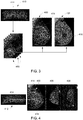
FIG. 3 is a schematic view of an identified region of interest from a 3D volume used to improve a correlated synthetic 2D image and navigation map according to an exemplary non-limiting embodiment of the invention. -
FIG. 4 is a schematic view of the display of the synthetic 2D image and overlaid region of interest identified in the 3D volume ofFIG. 3 , according to an exemplary non-limiting embodiment of the invention. -
FIG. 5 is a schematic view of the simultaneous display of a synthetic 2D image, a 3D plane and a 3D section along with selected pixel and a nipple position correlated via a navigation map according to an exemplary non-limiting embodiment of the invention. - Various embodiments will be better understood when read in conjunction with the appended drawings. To the extent that the figures illustrate diagrams of the functional blocks of various embodiments, the functional blocks are not necessarily indicative of the division between hardware circuitry. Thus, for example, one or more of the functional blocks (e.g., processors, controllers or memories) may be implemented in a single piece of hardware (e.g., a general purpose signal processor or random access memory, hard disk, or the like) or multiple pieces of hardware. Similarly, any programs may be stand-alone programs, may be incorporated as subroutines in an operating system, may be functions in an installed software package, and the like. It should be understood that the various embodiments are not limited to the arrangements and instrumentality shown in the drawings.
- As used herein, an element or step recited in the singular and proceeded with the word "a" or "an" should be understood as not excluding plural of said elements or steps, unless such exclusion is explicitly stated. Furthermore, references to "one embodiment" are not intended to be interpreted as excluding the existence of additional embodiments that also incorporate the recited features. Moreover, unless explicitly stated to the contrary, embodiments "comprising" or "having" an element or a plurality of elements having a particular property may include additional such elements not having that property.
- Also as used herein, the phrases "image" or "reconstructing an image" are not intended to exclude embodiments in which data representing an image is generated, but a viewable image is not. Therefore, as used herein the term "image" broadly refers to both viewable images and data representing a viewable image. However, many embodiments generate, or are configured to generate, at least one viewable image.
- Systems formed in accordance with various embodiments provide an imaging system including a 2D imaging modality (i.e., X-ray imaging) and a 3D imaging modality (e.g., ultrasound (US) or magnetic resonance imaging (MRI)) for performing scans on the object or patient using both modalities to enhance the scan results and diagnosis.
- Some embodiments provide an imaging system having a modified compression paddle that includes and/or accepts a cassette containing an ultrasound probe that can be moved to various locations within the field of view of the imaging system. For example, a control module utilizing appropriately configured software may obtain multiple X-ray images and an ultrasound scan to identify potential regions of interest, such as potential lesions, for further investigation. In some embodiments, a cassette containing an ultrasound probe may be positioned between a compression plate and an X-ray detector.
- Some exemplary embodiments provide for improved co-registration of X-ray and ultrasound images, for example by acquiring such images at substantially the same time and/or by acquiring such images utilizing a same or similar amount of compression.
- A technical effect of at least one embodiment includes reduced time required to acquire and analyze results of combined mammographic exams, including 2D imaging and 3D imaging exams. A technical effect of at least one embodiment includes reducing errors associated with multimodal imaging examinations. A technical effect of at least one embodiment includes improved co-registration of X-ray and ultrasound images, thereby improving and speeding up navigation between 2D and 3D images during review of the images, consequently improving diagnoses and/or reducing time and skill required by a medical professional for analysis of acquired images.
-
FIG. 1 provides an example of animaging system 200 for imaging an object in accordance with an exemplary embodiment, such as that disclosed inUS Patent Application Publication No. 2014/0135623 , entitled SYSTEMS AND METHODS FOR X-RAY AND ULTRASOUND IMAGING, which is expressly incorporated herein by reference in its entirety for all purposes. In the illustrated embodiment, thesystem 200 and associated method may employ structures or aspects of various embodiments discussed herein. In various embodiments, certain steps may be omitted or added, certain steps may be combined, certain steps may be performed simultaneously, certain steps may be performed concurrently, certain steps may be split into multiple steps, certain steps may be performed in a different order, or certain steps or series of steps may be re-performed in an iterative fashion. - In the system and method, an
object 202 is positioned between plates of an imaging system. For example, the object may be a portion of human anatomy such as a breast. Because X-ray scans effectively view an object in two dimensions (2D), structures such as breast tissue that exceed a certain density and/or thickness may not be readily amenable to X-ray scans. Compression may be used to render a breast more amenable to X-ray imaging. For example, compression may reduce the thickness of the breast, and stretch tissue to a wider viewing area in two dimensions, allowing for improved identification of structures located during a scan. Further, by presenting a thinner overall structure to an X-ray detecting system, the X-ray dosage required to image the breast may be reduced. - The exemplary illustrated embodiment of
FIG. 1 presents a schematic view of animaging system 200 formed in accordance with various embodiments. Theimaging system 200 is configured to provide both 2D (i.e., X-ray) and 3D (e.g., ultrasound or MRI or contrast-enhanced DBT, or CT) imaging modalities that may be used to perform scans on an object (e.g. a patient) in the same visit to a scanning location. For example, theimaging system 200 may be used to perform an X-ray scan and an ultrasound scan substantially consecutively. Substantially consecutively may be understood to describe, for example, scans that are performed with a relatively short time interval therebetween. In some embodiments, the 2D scan and the 3D scan may be performed substantially consecutively with a time interval of less than about 5 seconds therebetween. In some embodiments, the 2D scan and the 3D scan may be performed substantially consecutively with a time interval of less than about 10 seconds therebetween. In some embodiments, the 2D scan and the 3D scan may be performed substantially consecutively with a time interval of less than about 1 minute therebetween. In some embodiments, the 2D scan and the 3D scan may be performed substantially consecutively with a time interval of less than about 5 minutes therebetween. However, it should be appreciated that other time intervals are contemplated as well and that theimaging system 200 can be formed with separate devices for performing the 2D scan and 3D scan at different times and/or at different locations. - The
imaging system 200 may be used to image an object, such as ahuman breast 202. Theimaging system 200 may be articulable with respect to the object being imaged. In the illustrated embodiments, theimaging system 200 is articulable in arotational direction 206 and thus may be used to view thebreast 202 from a variety of angles for different scans. For example, a first X-ray scan may be performed at a first angle, and a second X-ray scan may be performed at a second angle to provide a different view of thebreast 202. Because thebreast 202 is a three-dimensional (3D) object and the X-ray scan effectively sees thebreast 202 in two dimensions, a structure within thebreast 202 may be obscured, blocked, or otherwise un-identifiable at one angle or view, but may be identifiable when viewed at a different angle or view. Thus, improved identification of structures within thebreast 202 may be achieved by performing X-ray scans at two or more different angles or views. - In the illustrated embodiment, the
system 200 is configured to obtain a 3-dimensional X-ray image, such as via 3D digital breast tomosynthesis (DBT). In some embodiments, tomosynthesis imaging information may be acquired utilizing a tube or other structure that may rotate between about 10 and 30 degrees in one or more directions to provide a volumetric image. In some embodiments, the amount of compression applied between plates or paddles may be reduced (e.g., in connection with the use of 3D DBT). For example, an amount of compression that is sufficient to position the object (e.g., breast) may be used. Thus, in various embodiments, various imaging techniques may be employed. Further, various mountings of an X-ray detection unit proximate to a plate or paddle may be employed (e.g., stationary or rotational). - The
imaging system 200 includes a 2D imaging orX-ray module 210, a3D imaging module 230, such as an ultrasound or MRI module, acontrol module 240, and aninterface 250. Generally speaking, in the illustrated embodiment, theX-ray module 210 is configured to perform an X-ray scan of theobject 202 at various angles with respect to theobject 202, such as in a DBT scan, and to provide X-ray imaging information to thecontrol module 240. Thecontrol module 240 is also configured to control the3D imaging module 230 to perform a scan of theobject 202 to facilitate improved analysis and/or diagnosis of theobject 202 and/or one or more regions of interest within theobject 202. For example, the 3D imaging scan may be used to confirm whether or not one or more regions of interest were false positives in the X-ray scan (e.g., not a cause for concern) or whether not one or more regions of interest appear to be of medical interest (e.g., potentially cancerous). - In the illustrated exemplary embodiment, the
X-ray module 210 includes anX-ray source 212, a paddle assembly 213 (including anupper plate 214 and a lower plate 216), adetector 218, and anactuator 220. TheX-ray source 212 is configured to emit X-rays that pass through an object (e.g., object 202) and are received by thedetector 218. The detector is position on, mounted to, and/or forms a part of thelower plate 216. Information acquired by thedetector 218 is communicated to thecontrol module 240. TheX-ray source 212 in the illustrated embodiment has a field ofview 204 that projects on to thedetector 218. - The
paddle assembly 213 includes anupper plate 214 andlower plate 216. Theupper plate 214 andlower plate 216 are an example of first and second opposed plates that are articulable with respect to each other. In the illustrated embodiment, thelower plate 216 is fixed and theupper plate 214 is articulable along acompression direction 222 by theactuator 220. Theupper plate 214 may be articulated downward (in the sense ofFIG. 2 ) toward thelower plate 216 to compress the breast and upward away from thelower plate 216 to reduce an amount of compression on thebreast 202 and/or to release thebreast 202 from between theupper plate 214 and thelower plate 216. In alternate embodiments, other arrangements may be employed to provide articulation of two plates with respect to each other. In the illustrated embodiment, theupper plate 214 and thelower plate 216 are depicted as substantially flat. In alternate embodiments, plates may be employed having curved or otherwise contoured profiles. Other types or orientations of articulation may be employed as well. As one example, in some embodiments, the first and second plates may be coupled by a pivot and thus be rotatable with respect to each other. Theactuator 220 may be controlled by thecontrol module 240 and/or an operator. In various embodiments, a variety of devices or mechanisms (e.g., one or more motors, pneumatic or hydraulic cylinders, electronic linear actuators, hand-operated mechanisms, or the like) may be employed to articulate the plates. In some embodiments, one or more paddles or plates may translate and/or rotate on a gantry which may be mounted to a floor and/or a wall. - In various embodiments, the
upper plate 214 and/or thelower plate 216 may be configured to reduce any potential attenuation (e.g., radiolucent) of an X-ray as the X-ray passes through the plates. Further, in various embodiments, theupper plate 214 and/or thelower plate 216 may be substantially transparent to provide an operator with visual confirmation of the positioning of theobject 202. - The
detector 218 is configured to receive X-ray beams that have been emitted from theX-ray source 212 and have passed through thebreast 202, and to provide X-ray imaging information to thecontrol module 240. Thecontrol module 240 is configured to receive the X-ray image information from thedetector 218 and/or to reconstruct 2D and/or 3D X-ray image(s) using the X-ray information from thedetector 218. In some embodiments, thedetector 218 may include more than one detector, such as an array of detectors. In the illustrated embodiment thedetector 218 is mounted to thelower plate 216. In other embodiments, thedetector 218 may be a part of, embedded within or otherwise associated with a plate or paddle. - In the illustrated exemplary embodiment, the 3D imaging module is constructed as an
ultrasound module 230, such as an automated breast ultrasound system (ABUS), that is configured to acquire ultrasound information of the object to be imaged. In the illustrated embodiment, theultrasound module 230 includes anultrasound transducer 232, a dispensing module 233, anactuator 234, and a reservoir 237. Theultrasound transducer 232 is configured to send an ultrasonic beam or beams through a portion of an object and to receive returned ultrasonic beams. Information acquired by the ultrasound transducer is then used to reconstruct a 3D image corresponding to the object, or portion thereof, that is scanned. For example, information from theultrasound transducer 232 may be communicated to thecontrol module 240 and/or theinterface 250 for image reconstruction and/or analysis. - In some embodiments, the
ultrasound transducer 232 includes an array of aligned transducers that are configured to be articulated in a substantially lateral direction, allowing for a region of interest of the breast to be ultrasonically scanned in a single pass. Theultrasound transducer 232 may be part of a cassette type assembly that is movable within and/or along a plate or paddle (as one example, anupper surface 215 of theupper plate 214, or, as another example, a lower surface of the lower plate 216). A liquid or gel may be employed to create or improve an acoustic contact between the ultrasound probe and a casing or surface of the plate or paddle. - The
actuator 234 is configured to articulate theultrasound transducer 232 to a desired position for scanning theobject 202 or a region of interest of the object (e.g., a region of interest of the breast 202). Theactuator 234 may position the ultrasound transducer based on control signals or messages received from thecontrol module 240. In the illustrated embodiment, theactuator 234 is configured to articulate theultrasound transducer 232 in anultrasound direction 236 substantially laterally along anupper surface 215 of theupper plate 214. In various embodiments, theactuator 234 may include one or more of a variety of devices or mechanisms (e.g., one or more motors, pneumatic or hydraulic cylinders, electronic linear actuators, or the like). - The
ultrasound transducer 232 may be positioned outside of the field ofview 204 of theX-ray source 212 while an X-ray scan is being performed. After the X-ray scan is complete and a region of interest has been selected, theactuator 234 may position theultrasound transducer 232 to scan theobject 202. Thus, theultrasound transducer 232 may be articulable between a position outside of the field ofview 204 and one or more positions inside of the field ofview 204. In some embodiments, the ultrasound transducer may be mounted to one or more paddles and plates, and articulable across one or more surfaces, for example, via a track or guide. In some embodiments, the ultrasound transducer may be movable in a plurality of lateral directions (e.g., theactuator 234 may include a plurality of linear actuators or otherwise be configured to articulate theultrasound transducer 232 in a plurality of directions). For example, theactuator 234 may be configured to move the ultrasound transducer in a raster pattern sized and configured to cover a region of interest. Further still, in some embodiments, theultrasound transducer 232 may be removably mounted to a paddle or plate, and physically removed from the paddle or plate during X-ray scanning. - The dispensing module 233 in the illustrated exemplary embodiment illustrated in
FIG. 1 includes a reservoir 237 (e.g., a sealed reservoir). The dispensing module 233 is configured to dispense a liquid or gel from the reservoir 237 to acoustically couple an ultrasound transducer with a surface of a plate or paddle. For example, in the illustrated embodiment, the dispensing module 233 is configured to dispense a liquid to theupper surface 215 of theupper plate 214 over which theultrasound transducer 232 traverses during ultrasound scanning of one or more regions of interest. The liquid or gel is configured to improve the acoustic contact between a transducer and a plate or paddle, so that soundwaves may be transmitted between the transducer and the object via the plate or paddle (e.g., with the plate or paddle pressed against the object to be scanned as the object is compressed). In some embodiments, a portion of the dispensing module and/or a surface of a plate or paddle may be configured to improve retention of liquid or gel on the surface when theimaging system 200 is articulated in therotational direction 206 at an angle in which gravity may urge the liquid or gel off of the surface. - The
control module 240 includes amotion control module 244 that is configured to control movement and/or position of theX-ray source 212, theplates ultrasound transducer 232 to scan theobject 202 and/or a region of interest within theobject 202. - The
analysis module 242 ofcontrol module 240 is configured to receive information from thedetector 218 of theX-ray module 210 and theultrasound transducer 232, and to reconstruct 2D and 3D images using the information using each image data set. Theanalysis module 242 may also be configured, for example, to adjust or account for compression when reconstructing an image using ultrasound information from theultrasound transducer 232. In some embodiments, reconstructed X-ray and/or ultrasound images may be provided by the control module to a practitioner or other system via thedisplay 252 on theinterface 250. - In the illustrated embodiments, the
analysis module 242 may include or have access to software, such as a computer-aided detection (CAD) system, that facilitates the identification of lesions or other regions of interest in a 2D image(s) and/or the 3D images provided by the X-ray and ultrasound scans. In some embodiments, thecontrol module 240 may receive an input from a practitioner, such as through theinterface 250, identifying one or more regions of interest. For example, in some embodiments, theanalysis module 242 is configured to autonomously identify one or more potential lesions or other aspects of interest based on X-ray information received from thedetector 218. In some embodiments, the region or regions of interest may be identified by a practitioner based on an analysis of one or more of the 2D and/or 3D images on thedisplay 252. - The
interface 250 is configured to allow information and/or commands to be communicated between thecontrol module 240 and a practitioner. In the illustrated embodiments, theinterface 250 includes adisplay module 252 and aninput module 254. Thedisplay module 252 may include, for example, a printer, a screen, a touchscreen, a speaker, or the like. Theinput module 254 may include a touchscreen (e.g., a touchscreen shared between thedisplay module 252 and the input module 254), a mouse, stylus, keyboard, keypad, or the like. One or more reconstructed images may be displayed via thedisplay module 252. - The
input module 254 is configured to receive input from a practitioner to perform one or more imaging activities. For example, theinput module 254 may receive input from a practitioner establishing one or more settings or parameters for imaging. Further, theinput module 254 may receive input from a practitioner establishing a region of interest within the images for further evaluation or display. - In one exemplary embodiment of the
system 200, after the 2D and 3D imaging scans of theobject 202 have been performed, theanalysis module 242 will generate synthetic 2D image(s) and 3D images/volumes of theobject 202 from the X-ray/DBT/full filed digital mammography (FFDM)/contrast-enhanced spectral mammography (CESM) scans performed by theX-ray source 212 and the data provided by theX-ray detector 218 to theanalysis module 242. An exemplary embodiment of a DBT/DBT-FFDM/DBT-CESM imaging process performed on the image data from theX-ray detector 218 is disclosed inUS Patent No. 8,126,226 , entitled SYSTEM AND METHOD TO GENERATE A SELECTED VISUALIZATION OF A RADIOLOGICAL IMAGE OF AN IMAGED SUBJECT, and in US Patent Application Publication No.US2016/0189376 , entitled METHOD AND SYSTEM FOR OBTAINING LOW DOSE TOMOSYNTHESIS AND MATERIAL DECOMPOSITION IMAGES, the entirety of which are each expressly incorporated by reference herein for all purposes. In addition, theanalysis module 242 can employ the images from theultrasound transducer 232 to generate a 3D volume of theobject 202. - In another exemplary embodiment, the system and method for acquiring and processing 2D and 3D imaging data for improving navigation through the imaging data may include the acquisition of 2D and 3D imaging data from a separate and independent DBT X-ray imaging system and a separate and independent ABUS ultrasound imaging system.
- Looking now at
FIG. 2 , in generating both the synthetic 2D image(s) and 3D volume(s) containing a number of planar views of the imaged tissue from the DBT acquisition or scan, theanalysis module 242 maps location of any point on thesynthetic 2D image 400 to the location of a voxel within the generated3D DBT volume 405. As such, for anysynthetic 2D image 400 presented to the user on thedisplay 252, theanalysis module 242 creates an associated but hiddennavigation map 402 for theimage 400 containing the height or z-axis information for any (x,y)pixel 404 on thesynthetic 2D image 400. The z-axis information associated with each (x,y)pixel 404 is correlated by theanalysis module 242 to the corresponding z-axis plane 406 of the3D DBT volume 405. This process is described inUS8126226 along withUS9842415 - Further, with the information on the z-
axis plane 406 in the3D DBT volume 405, theanalysis module 242 can correlate the (x,y,z) location in the DBT z-axis plane 406 to a corresponding section orplane 408 of the automated breast ultrasound system (ABUS) or MRI 3D or CEDBT orCT volume 410. TheDBT plane 406 to ABUS/MRI/CEDBT/CT plane orsection 408 correspondence can require a quite straightforward transformation when the image modalities were obtained at the same time and/or with theobject 202 in the same position and/or compression in thesystem 200, though some resolution scaling may need to be performed. - Alternatively, the
DBT plane 406 to ABUS/MRI/CEDBT/CT section 408 correspondence can require their positions in the respective 3D volumes 405,410 to be correlated using a suitable transformation to accommodate for the changes in position of the object/tissue 202 (e.g., compression of the object/tissue 202) between imaging modalities. The registration process could rely on matching findings detected in theDBT volume 405 and ABUS/MRI/CEDBT/CT volume 410, such as for example, by utilizing finite element model in a known manner, and/or by employing a linear affine transformation-MLO translation utilizing the compression angle from the dicom header from the ABUS images. For registration or translation of theDBT volume 405 to an MRI/CT volume 410, the lack of compression performed in the MRI/CT scan enables finite element modeling to be effectively utilized to transform the MRI/CT scan volume 410 to register it to theDBT volume 405. - With this mapping of the
pixels 404 in the synthetic2D DBT image 400 to theDBT volume 405, and the corresponding correlation and/or registration of theDBT volume 405 to the 3D imaging (ABUS or MRI or CEDBT or CT)volume 410, in the review of thesynthetic 2D image 400 on thedisplay 252 by the radiologist, the selection of an (x,y)pixel 404 corresponding to a potential region of interest within thesynthetic 2D image 400 being reviewed allows theanalysis module 242 to access and read thenavigation map 402 to determine the z-axis information for thatpixel 404. In a particular embodiment, theanalysis module 242 can then automatically utilize the z-axis information for thepixel 404 selected to locate thecorresponding DBT plane 406 and the ABUS/MRI/CEDBT/CT section 408 registered with thatDBT plane 406, which, e.g., can be an axial or coronal plane/view of theABUS volume 410 created in a process disclosed in US Patent Application Publication No.US20100076311 , entitled THICK SLICE PROCESSING AND DISPLAY OF INFORMATION FROM A VOLUMETRIC ULTRASOUND SCAN OF A CHESTWARDLY COMPRESSED BREAST, which is expressly incorporated by reference herein in its entirety for all purposes. Theanalysis module 242 can then present the ABUS/MRI section 408, and optionally theDBT plane 406, on thedisplay 252 in conjunction with thesynthetic 2D image 400 with a cross orcursor 412 on each image 400,406,408 indicating the corresponding precise position of thepixel 404 selected in theimage 400. As a result the speed of navigation between the DBT and ABUS/MRI/CEDBT/CT image data sets/volumes is greatly enhanced, consequently speeding up the overall workflow when reading DBT and ABUS/MRI/CEDBT/CT volumes - Referring now to
FIG. 3 , in another exemplary embodiment of the disclosure theanalysis module 242 can be utilized to identify volumes of interest (VOIs) or regions of interest (ROIs) 414 in the ABUS/MRI/CEDBT/CT volume 410. This identification of the VOIs/ROIs 414 can be performed manually by the user through theinterface input 254 during a review of the ABUS/MRI/CEDBT/CT volume 410, or can be performed automatically using a computer aided detection (CAD) system 413 associated with theanalysis module 242. Ascertain ROIs 414 are more readily detectable/visible in theABUS volume 410 than in theDBT volume 405, the identification of theROIs 414 in the ABUS/MRI/CEDBT/CT volume 410 can be used to mitigate both the omission of theROIs 414 in theDBT volume 405 and the rate of false positives where theROI 414 is present in the ABUS/MRI/CEDBT/CT volume 410 but not in theDBT volume 405. - Once identified in the ABUS/MRI/CEDBT/
CT volume 410, the correlation of the ABUS/MRI/CEDBT/CT volume 410 to theDBT volume 405 allows for the locations of theROIs 414 to be translated into theDBT volume 405 where theROIs 414 can be represented in thesynthetic 2D image 400 generated by theanalysis module 242 using a reprojection operation. Additionally, in other exemplary embodiments the representation of the VOI/ROI 414 in thesynthetic 2D image 400 can include a boundary for the VOI/ROI 414 overlaid within thesynthetic 2D image 400. Optionally, the ROI/VOI 414 as obtained from theDBT volume 405 can also be blended onto the existingsynthetic 2D image 400. Alternatively, the syntheticimage DBT images 400 are enhanced/enriched during the generation process for thesynthetic 2D image 400, such as that disclosed inUS Patent No. 9,842,415 US2016/0183901 , entitled METHOD AND SYSTEM FOR TOMOSYNTHESIS PROJECTION IMAGES ENHANCEMENT, which are each expressly incorporated herein by reference in their entirety for all purposes, to take theROIs 414 position into account and avoid non-relevant overlapping tissues within the presentedimage 400. - In addition, the
navigation map 402 can be modified accordingly to direct the user upon the selection ofpixels 404 within the modifiedarea 416 of themap 402 to the corresponding ABUS/MRI/CEDBT/CT section 408 including the VOI/ROI 414, thereby providing more efficient synthetic 2D to DBT/ABUS/MRI/CEDBT/CT navigation. In particular, with reference to the exemplary embodiment illustrated inFIG. 4 , with the ability to represent the VOIs/ROIs 414 overlaid in thesynthetic 2D image 400 that are manually identified or identified using the CAD system 413 in the ABUS/MRI/CEDBT/CT volume 410. The selection of a VOI/ROI 414 represented on thesynthetic 2D image 400 instructs theanalysis module 242 to present thecorresponding DBT plane 406 and/or ABUS/MRI/CEDBT/CT plane/section 408 on thedisplay 252 for a side-by-side comparison of the planes of interest carrying the multi-modality information on the selected VOI/ROI 414. - Looking now at
FIG. 5 , in addition to theROIs 414 that are identified in the ABUS/MRI volume 410 and correlated into thesynthetic 2D image 400 andDBT volume 405, the position of thenipple 418 is represented in the ABUS/MRI volume 410 with high precision, but is not readily apparent in thesynthetic 2D image 400 or3D volume 405. Thus, with the correlation or registration of the ABUS/MRI volume 410 to theDBT volume 405 andsynthetic 2D image 400, the position of thenipple 418 can be represented/re-projected onto thesynthetic 2D image 400 and the3D volume 405. When apixel 404 representing anROI 414 on thesynthetic 2D image 400 is selected on thedisplay 252 by the user, thenipple position 418 can be presented on the synthetic 2D image(s) 400, the DBT plane 406 (if presented) and optionally on the ABUS/MRI section 410 corresponding to the information contained within thenavigation map 402 associated with thepixel 404. In addition, theimages ROI 414 to thenipple 418, a clockwise position of the VOI/ROI 414 with respect to thenipple 418 and the distance of the VOI/ROI 414 from the skin line 420. This information is reported for further treatment wherein VOI/ROI 414 localization in the anatomy is required as biopsy. - The written description uses examples to disclose the invention, including the best mode, and also to enable any person skilled in the art to practice the invention, including making and using any devices or systems and performing any incorporated methods. The patentable scope of the invention is defined by the claims, and may include other examples that occur to those skilled in the art. Such other examples are intended to be within the scope of the claims if they have structural elements that do not differ from the literal language of the claims, or if they include equivalent structural elements with insubstantial differences from the literal language of the claims.
Claims (22)
- A method of navigating between images of an object obtained in different imaging modalities of the object, the method comprising:obtaining a number of x-ray images of the object at varying angles relative to the object in a digital breast tomosynthesis (DBT) acquisition;obtaining a three-dimensional (3D) volumetric image of the object in a 3D imaging acquisition;forming a DBT volume of the object from the x-ray images;forming a synthetic two-dimensional (2D) image of the object from the x-ray images and/or the DBT volume;forming a navigation map correlating pixels of the synthetic 2D image with associated planes in the DBT volume;correlating the 3D volumetric image from the 3D imaging acquisition with the DBT volume from the DBT acquisition;displaying the synthetic 2D image; anddisplaying a section of the 3D volumetric image corresponding to a location of a pixel in the synthetic 2D image in response to a selection of the pixel in the displayed synthetic 2D image.
- A method according to claim 1 wherein the 3D imaging acquisition is an ultrasound (US) acquisition.
- A method according to claim 1 wherein the 3D imaging acquisition is a magnetic resonance imaging (MRI) acquisition.
- A method according to claim 1 wherein the 3D imaging acquisition is a contrast enhanced DBT (CEDBT) acquisition.
- A method according to claim 1 wherein the 3D imaging acquisition is a CT acquisition.
- A method according to claim 1 wherein the registration of the 3D volumetric image to the DBT volume comprises employing a finite element model.
- A method according to claim 1 wherein the registration of the 3D volumetric image to the DBT volume comprises matching findings in the 3D volumetric image and the DBT volume.
- A method according to claim 1 wherein the step of obtaining a number of x-ray images of the object and the step of obtaining a 3D volumetric image of the object occur with the object in the same position.
- A method according to claim 1 wherein the step of forming the navigation map comprises associating a height value to each pixel of the synthetic 2D image corresponding to a position in the 3D volumetric image.
- A method according to claim 1 wherein the step of forming the synthetic 2D image further comprises the steps of:detecting one or more volumes of interest (VOIs) within the 3D volumetric image;determining the positions of the one or more VOIs from the 3D volumetric image within the DBT volume;reprojecting the VOIs from the DBT volume; andmodifying the navigation map to include the location of the VOIs.
- A method according to claim 10 wherein the VOI reprojections are blended onto the synthetic 2D image after formation of the synthetic 2D image.
- A method according to claim 10 wherein the VOI reprojections are utilized to enrich the synthetic 2D image during formation of the synthetic 2D image.
- A method according to claim 10 further comprising the step of representing a boundary overlay of the VOI from the DBT volume within the synthetic 2D image.
- A method according to claim 1 further comprising the steps of:detecting a position of the nipple within the 3D volumetric image;locating the position of the nipple from the 3D volumetric image into the DBT volume; andrepresenting the nipple in the synthetic 2D image.
- A method according to claim 14 wherein the step of representing the nipple in the synthetic 2D image includes representing a distance from a selected pixel in the synthetic 2D image to the nipple.
- A method according to claim 14 wherein the step of representing the nipple in the synthetic 2D image includes representing a clockwise position relative to the nipple of a selected pixel in the synthetic 2D image.
- A method according to claim 1 further comprising the step of illustrating a cursor on the synthetic 2D image and the section of the 3D volumetric image on the display, wherein the cursor represents the location of the selected pixel in the synthetic 2D image and the corresponding position in the section of the 3D volumetric image.
- A system for assisting a user in navigating through 2D and 3D image data to locate a region of interest within a breast tissue, the system comprising:a 2D image acquisition system for acquiring 2D image data;a 3D image acquisition system for acquiring 3D image data;an analysis module operably connected to the 2D image acquisition system and the 3D image acquisition system and configured:to generate a synthetic 2D image and a DBT volume from the acquired 2D image data;to generate a 3D volume from the 3D image data;to correlate locations within the DBT volume to locations within the 3D image volume;to generate a navigation map providing information for each pixel in the synthetic 2D image corresponding to a plane in the DBT volume and the 3D image volume; andto select and present a section within the 3D volume corresponding to the navigation map information for a pixel selected within the synthetic 2D image;a display operably connected to the analysis module and operable to display the synthetic 2D image and sections of the 3D volume; andan input operably connected to the analysis module and configured to receive commands from a user regarding the selection of a pixel within the synthetic 2D image present on the display.
- A system according to claim 18 wherein the 3D image acquisition system is an automated breast ultrasound system (ABUS) or a magnetic resonance imaging (MRI) system.
- A system according to claim 18 further comprising a computer aided detection system associated with the analysis module and configured with the analysis module to:detect regions of interest within the 3D volume;update the navigation map with the locations of the regions of interest (ROIs); andoptionally enhance the synthetic 2D image to illustrate the ROIs.
- A system according to claim 18 wherein the analysis module presents a cursor on the synthetic 2D image and the section of the 3D volume on the display, wherein the cursor represents the location of the selected pixel in the synthetic 2D image and the section of the 3D volume.
- A system according to claim 18 wherein the analysis module is further configured to:detect a position of the nipple within the 3D volume;locating the position of the nipple from the 3D volume into the DBT volume; andrepresent the nipple and information on the location of the selected pixel relative to the nipple on the display in the synthetic 2D image formed from DBT volume and in the section of the 3D volume.
Applications Claiming Priority (1)
| Application Number | Priority Date | Filing Date | Title |
|---|---|---|---|
| US15/960,803 US10796430B2 (en) | 2018-04-24 | 2018-04-24 | Multimodality 2D to 3D imaging navigation |
Publications (2)
| Publication Number | Publication Date |
|---|---|
| EP3560424A1 true EP3560424A1 (en) | 2019-10-30 |
| EP3560424B1 EP3560424B1 (en) | 2025-01-15 |
Family
ID=66286139
Family Applications (1)
| Application Number | Title | Priority Date | Filing Date |
|---|---|---|---|
| EP19170954.2A Active EP3560424B1 (en) | 2018-04-24 | 2019-04-24 | Multimodality 2d to 3d imaging navigation |
Country Status (4)
| Country | Link |
|---|---|
| US (1) | US10796430B2 (en) |
| EP (1) | EP3560424B1 (en) |
| CN (1) | CN110393591B (en) |
| ES (1) | ES3015127T3 (en) |
Cited By (1)
| Publication number | Priority date | Publication date | Assignee | Title |
|---|---|---|---|---|
| WO2023160720A1 (en) * | 2022-02-28 | 2023-08-31 | Shanghai United Imaging Healthcare Co., Ltd. | Methods, systems, and storage mediums for image generation |
Families Citing this family (24)
| Publication number | Priority date | Publication date | Assignee | Title |
|---|---|---|---|---|
| WO2013078476A1 (en) | 2011-11-27 | 2013-05-30 | Hologic, Inc. | System and method for generating a 2d image using mammography and/or tomosynthesis image data |
| WO2007095330A2 (en) | 2006-02-15 | 2007-08-23 | Hologic Inc | Breast biopsy and needle localization using tomosynthesis systems |
| CN102481146B (en) | 2009-10-08 | 2016-08-17 | 霍罗吉克公司 | Breast needle biopsy system and method of use thereof |
| JP6057922B2 (en) | 2011-03-08 | 2017-01-11 | ホロジック, インコーポレイテッドHologic, Inc. | System and method for dual energy and / or contrast enhanced breast imaging for screening, diagnosis and biopsy |
| WO2013123091A1 (en) | 2012-02-13 | 2013-08-22 | Hologic, Inc. | System and method for navigating a tomosynthesis stack using synthesized image data |
| WO2014151646A1 (en) | 2013-03-15 | 2014-09-25 | Hologic Inc. | Tomosynthesis-guided biopsy in prone |
| US10624598B2 (en) | 2013-03-15 | 2020-04-21 | Hologic, Inc. | System and method for navigating a tomosynthesis stack including automatic focusing |
| US10111631B2 (en) | 2014-02-28 | 2018-10-30 | Hologic, Inc. | System and method for generating and displaying tomosynthesis image slabs |
| CN110621233B (en) | 2017-03-30 | 2023-12-12 | 豪洛捷公司 | Methods for processing breast tissue image data |
| EP3600047A1 (en) | 2017-03-30 | 2020-02-05 | Hologic, Inc. | System and method for hierarchical multi-level feature image synthesis and representation |
| WO2019045144A1 (en) * | 2017-08-31 | 2019-03-07 | (주)레벨소프트 | Medical image processing apparatus and medical image processing method which are for medical navigation device |
| CN112804944B (en) | 2018-09-24 | 2024-07-23 | 豪洛捷公司 | Breast mapping and abnormality localization |
| JP7023254B2 (en) * | 2019-03-27 | 2022-02-21 | 富士フイルム株式会社 | Shooting support equipment, methods and programs |
| CN111275617B (en) * | 2020-01-09 | 2023-04-07 | 云南大学 | Automatic splicing method and system for ABUS breast ultrasound panorama and storage medium |
| AU2021241536A1 (en) | 2020-03-27 | 2022-08-18 | Hologic, Inc. | Systems and methods for identifying regions of interest in multiple imaging modalities |
| JP2023519878A (en) | 2020-03-27 | 2023-05-15 | ホロジック, インコーポレイテッド | Systems and methods for correlating regions of interest in multiple imaging modalities |
| EP4218595B1 (en) * | 2020-09-28 | 2025-12-17 | FUJIFILM Corporation | Ultrasonic diagnostic device and method for controlling ultrasonic diagnostic device |
| US11963670B2 (en) * | 2021-03-01 | 2024-04-23 | GE Precision Healthcare LLC | Systems and methods for identifying biopsy location coordinates |
| JP7672892B2 (en) * | 2021-06-17 | 2025-05-08 | キヤノンメディカルシステムズ株式会社 | Medical image processing device, ultrasound diagnostic device, and program |
| US12254586B2 (en) * | 2021-10-25 | 2025-03-18 | Hologic, Inc. | Auto-focus tool for multimodality image review |
| IL313196A (en) | 2021-11-29 | 2024-07-01 | Hologic Inc | Systems and methods for determining correlations between objects of interest |
| EP4254350A1 (en) * | 2022-04-01 | 2023-10-04 | Siemens Healthcare GmbH | Determination of illumination parameters in medical image rendering |
| CN114430482B (en) * | 2022-04-02 | 2022-08-05 | 深圳市即达健康医疗科技有限公司 | Holographic diagnosis system, method, computer equipment and storage medium |
| WO2024223029A1 (en) * | 2023-04-25 | 2024-10-31 | Supersonic Imagine | A method of determining an ultrasound acquisition parameter |
Citations (9)
| Publication number | Priority date | Publication date | Assignee | Title |
|---|---|---|---|---|
| US20030149364A1 (en) * | 2002-02-01 | 2003-08-07 | Ajay Kapur | Methods, system and apparatus for digital imaging |
| US20090080765A1 (en) * | 2007-09-20 | 2009-03-26 | General Electric Company | System and method to generate a selected visualization of a radiological image of an imaged subject |
| US20100076311A1 (en) | 2006-09-22 | 2010-03-25 | U-Systems, Inc. | Thick-slice processing and display of information from a volumetric ultrasound scan of a chestwardly compressed breast |
| US20120293511A1 (en) * | 2010-02-25 | 2012-11-22 | Siemens Aktiengesellschaft | Method for displaying an area to be medically examined and/or treated |
| US20140082542A1 (en) | 2010-07-19 | 2014-03-20 | Qview, Inc. | Viewing and correlating between breast ultrasound and mammogram or breast tomosynthesis images |
| US20140135623A1 (en) | 2012-11-15 | 2014-05-15 | General Electric Company | Systems and methods for x-ray and ultrasound imaging |
| US20160183901A1 (en) | 2014-12-31 | 2016-06-30 | General Electric Company | Method and system for tomosynthesis projection images enhancement |
| US20160189376A1 (en) | 2014-12-24 | 2016-06-30 | General Electric Company | Method and system for obtaining low dose tomosynthesis and material decomposition images |
| US9842415B2 (en) | 2009-12-22 | 2017-12-12 | General Electric Company | Method for processing tomosynthesis acquisitions in order to obtain a representation of the contents of an organ |
Family Cites Families (35)
| Publication number | Priority date | Publication date | Assignee | Title |
|---|---|---|---|---|
| US5672877A (en) | 1996-03-27 | 1997-09-30 | Adac Laboratories | Coregistration of multi-modality data in a medical imaging system |
| US20050089205A1 (en) | 2003-10-23 | 2005-04-28 | Ajay Kapur | Systems and methods for viewing an abnormality in different kinds of images |
| WO2006017172A1 (en) | 2004-07-09 | 2006-02-16 | Fischer Imaging Corporation | Diagnostic system for multimodality mammography |
| US8326006B2 (en) | 2004-07-09 | 2012-12-04 | Suri Jasjit S | Method for breast screening in fused mammography |
| ATE469424T1 (en) | 2004-07-30 | 2010-06-15 | Fischer Imaging Corp | IMAGING DEVICE FOR FUSIONED MAMMOGRAPHY WITH INDEPENDENTLY MOVABLE IMAGING SYSTEMS OF DIFFERENT MODALITIES |
| US7639896B2 (en) | 2004-08-09 | 2009-12-29 | Carestream Health, Inc. | Multimodal image registration using compound mutual information |
| EP1828981A2 (en) | 2004-12-15 | 2007-09-05 | Koninklijke Philips Electronics N.V. | Registration of multi-modality images |
| US20060136259A1 (en) | 2004-12-17 | 2006-06-22 | General Electric Company | Multi-dimensional analysis of medical data |
| US20070003118A1 (en) | 2005-06-30 | 2007-01-04 | Wheeler Frederick W | Method and system for projective comparative image analysis and diagnosis |
| US7738683B2 (en) | 2005-07-22 | 2010-06-15 | Carestream Health, Inc. | Abnormality detection in medical images |
| US20070237372A1 (en) | 2005-12-29 | 2007-10-11 | Shoupu Chen | Cross-time and cross-modality inspection for medical image diagnosis |
| US7945083B2 (en) | 2006-05-25 | 2011-05-17 | Carestream Health, Inc. | Method for supporting diagnostic workflow from a medical imaging apparatus |
| US8527293B2 (en) | 2007-03-30 | 2013-09-03 | General Electric Company | Method and system for supporting clinical decision-making |
| US20080242979A1 (en) | 2007-03-30 | 2008-10-02 | Rayette Ann Fisher | Combined X-ray detector and ultrasound imager |
| US20120093383A1 (en) | 2007-03-30 | 2012-04-19 | General Electric Company | Sequential image acquisition method |
| US20090082637A1 (en) | 2007-09-21 | 2009-03-26 | Michael Galperin | Multi-modality fusion classifier with integrated non-imaging factors |
| BRPI0821291B1 (en) | 2007-12-21 | 2020-10-06 | Koninklijke Philips N. V | METHOD THAT UNDERSTANDS STORING PLURALITY OF OCCURRENCES, SYSTEM THAT UNDERSTANDS A MEMORY STORING PLURALITY OF OCCURRENCES AND SYSTEM THAT UNDERSTANDS RESOURCES TO STORE PLURALITY OF OCCURRENCES |
| DE102008009967A1 (en) | 2008-02-20 | 2009-09-17 | Siemens Aktiengesellschaft | Mammography system and method for sonographic and radiographic examination of a breast |
| EP2303127A1 (en) | 2008-06-11 | 2011-04-06 | Koninklijke Philips Electronics N.V. | Multiple modality computer aided diagnostic system and method |
| EP2194506B1 (en) | 2008-12-02 | 2016-03-09 | Samsung Medison Co., Ltd. | Image based registration |
| CN102473300B (en) * | 2009-07-17 | 2016-03-30 | 皇家飞利浦电子股份有限公司 | multi-modality breast imaging |
| US9451924B2 (en) | 2009-12-30 | 2016-09-27 | General Electric Company | Single screen multi-modality imaging displays |
| US9401047B2 (en) | 2010-04-15 | 2016-07-26 | Siemens Medical Solutions, Usa, Inc. | Enhanced visualization of medical image data |
| US10282840B2 (en) * | 2010-07-21 | 2019-05-07 | Armin Moehrle | Image reporting method |
| RU2595628C2 (en) * | 2010-10-19 | 2016-08-27 | Конинклейке Филипс Электроникс Н.В. | Medical imaging system |
| WO2012096882A1 (en) | 2011-01-11 | 2012-07-19 | Rutgers, The State University Of New Jersey | Method and apparatus for segmentation and registration of longitudinal images |
| US9378550B2 (en) | 2011-03-02 | 2016-06-28 | Mevis Medical Solutions Ag | Image processing device for finding corresponding regions in two image data sets of an object |
| US20120256920A1 (en) | 2011-04-05 | 2012-10-11 | Julian Marshall | System and Method for Fusing Computer Assisted Detection in a Multi-Modality, Multi-Dimensional Breast Imaging Environment |
| US20130211230A1 (en) | 2012-02-08 | 2013-08-15 | Convergent Life Sciences, Inc. | System and method for using medical image fusion |
| EP3005298B1 (en) * | 2013-06-06 | 2019-04-17 | Volpara Health Technologies Limited | A method of reconstruction of an object from projection views |
| EP3071108A1 (en) * | 2013-11-18 | 2016-09-28 | Koninklijke Philips N.V. | One or more two dimensional (2d) planning projection images based on three dimensional (3d) pre-scan image data |
| WO2016142492A1 (en) * | 2015-03-10 | 2016-09-15 | Koninklijke Philips N.V. | Retrieval of corresponding structures in pairs of medical images |
| US9792703B2 (en) * | 2015-07-06 | 2017-10-17 | Siemens Healthcare Gmbh | Generating a synthetic two-dimensional mammogram |
| US9984478B2 (en) * | 2015-07-28 | 2018-05-29 | PME IP Pty Ltd | Apparatus and method for visualizing digital breast tomosynthesis and other volumetric images |
| US10716525B2 (en) * | 2015-08-06 | 2020-07-21 | Covidien Lp | System and method for navigating to target and performing procedure on target utilizing fluoroscopic-based local three dimensional volume reconstruction |
-
2018
- 2018-04-24 US US15/960,803 patent/US10796430B2/en active Active
-
2019
- 2019-04-24 CN CN201910337148.7A patent/CN110393591B/en active Active
- 2019-04-24 ES ES19170954T patent/ES3015127T3/en active Active
- 2019-04-24 EP EP19170954.2A patent/EP3560424B1/en active Active
Patent Citations (10)
| Publication number | Priority date | Publication date | Assignee | Title |
|---|---|---|---|---|
| US20030149364A1 (en) * | 2002-02-01 | 2003-08-07 | Ajay Kapur | Methods, system and apparatus for digital imaging |
| US20100076311A1 (en) | 2006-09-22 | 2010-03-25 | U-Systems, Inc. | Thick-slice processing and display of information from a volumetric ultrasound scan of a chestwardly compressed breast |
| US20090080765A1 (en) * | 2007-09-20 | 2009-03-26 | General Electric Company | System and method to generate a selected visualization of a radiological image of an imaged subject |
| US8126226B2 (en) | 2007-09-20 | 2012-02-28 | General Electric Company | System and method to generate a selected visualization of a radiological image of an imaged subject |
| US9842415B2 (en) | 2009-12-22 | 2017-12-12 | General Electric Company | Method for processing tomosynthesis acquisitions in order to obtain a representation of the contents of an organ |
| US20120293511A1 (en) * | 2010-02-25 | 2012-11-22 | Siemens Aktiengesellschaft | Method for displaying an area to be medically examined and/or treated |
| US20140082542A1 (en) | 2010-07-19 | 2014-03-20 | Qview, Inc. | Viewing and correlating between breast ultrasound and mammogram or breast tomosynthesis images |
| US20140135623A1 (en) | 2012-11-15 | 2014-05-15 | General Electric Company | Systems and methods for x-ray and ultrasound imaging |
| US20160189376A1 (en) | 2014-12-24 | 2016-06-30 | General Electric Company | Method and system for obtaining low dose tomosynthesis and material decomposition images |
| US20160183901A1 (en) | 2014-12-31 | 2016-06-30 | General Electric Company | Method and system for tomosynthesis projection images enhancement |
Cited By (1)
| Publication number | Priority date | Publication date | Assignee | Title |
|---|---|---|---|---|
| WO2023160720A1 (en) * | 2022-02-28 | 2023-08-31 | Shanghai United Imaging Healthcare Co., Ltd. | Methods, systems, and storage mediums for image generation |
Also Published As
| Publication number | Publication date |
|---|---|
| US20190325573A1 (en) | 2019-10-24 |
| CN110393591B (en) | 2022-09-13 |
| CN110393591A (en) | 2019-11-01 |
| US10796430B2 (en) | 2020-10-06 |
| EP3560424B1 (en) | 2025-01-15 |
| ES3015127T3 (en) | 2025-04-29 |
Similar Documents
| Publication | Publication Date | Title |
|---|---|---|
| EP3560424B1 (en) | Multimodality 2d to 3d imaging navigation | |
| US11730442B2 (en) | System and method for fusing three dimensional image data from a plurality of different imaging systems for use in diagnostic imaging | |
| US12505645B2 (en) | Systems and methods for correlating regions of interest in multiple imaging modalities | |
| JP7431729B2 (en) | Ultrasound system and method for correlating ultrasound chest images with chest images from other imaging modalities | |
| Rella et al. | Automated breast ultrasonography (ABUS) in the screening and diagnostic setting: indications and practical use | |
| EP3871603B1 (en) | Methods and systems for digital mammography imaging | |
| CN101273919B (en) | Sequential image acquisition with updating method and system | |
| JP5893290B2 (en) | Image processing method for determining suspicious areas of tissue matrix, and use of the method in 3D navigation across tissue matrix | |
| US20140135623A1 (en) | Systems and methods for x-ray and ultrasound imaging | |
| Huang et al. | 2.5-D extended field-of-view ultrasound | |
| US20120078101A1 (en) | Ultrasound system for displaying slice of object and method thereof | |
| Jiang et al. | A semi-automated 3-D annotation method for breast ultrasound imaging: system development and feasibility study on phantoms | |
| WO2022097524A1 (en) | Image processing device, method and program, and image display device, method and program | |
| RU2779836C2 (en) | Ultrasound system and method for correlation between ultrasound breast images and breast images of other imaging methods | |
| Hopp et al. | 2D/3D image fusion of x-ray mammograms with speed of sound images: evaluation and visualization | |
| McDonald | 3-Dimensional breast ultrasonography: What have we been missing? | |
| Costa | Automated Deformable Registration of Breast Images: towards a software-assisted multimodal breast image reading | |
| Blank et al. | From Sweeps to Volumes: 3D Multiscan Stitching Enables Operator-Independent, Large-Area Abdominal Ultrasound—A Phantom-and-Patient Feasibility Study | |
| Jiang | Development of a 3D breast ultrasound system for providing automated annotation and coronal images | |
| CN120078438A (en) | System and method for generating predicted views for improved mammographic imaging system positioning | |
| McDonald | Ultrasonography: What Have We Been | |
| Huang | Development of a portable 3D ultrasound system for imaging and measurement of musculoskeletal body parts |
Legal Events
| Date | Code | Title | Description |
|---|---|---|---|
| PUAI | Public reference made under article 153(3) epc to a published international application that has entered the european phase |
Free format text: ORIGINAL CODE: 0009012 |
|
| STAA | Information on the status of an ep patent application or granted ep patent |
Free format text: STATUS: REQUEST FOR EXAMINATION WAS MADE |
|
| 17P | Request for examination filed |
Effective date: 20190424 |
|
| AK | Designated contracting states |
Kind code of ref document: A1 Designated state(s): AL AT BE BG CH CY CZ DE DK EE ES FI FR GB GR HR HU IE IS IT LI LT LU LV MC MK MT NL NO PL PT RO RS SE SI SK SM TR |
|
| AX | Request for extension of the european patent |
Extension state: BA ME |
|
| STAA | Information on the status of an ep patent application or granted ep patent |
Free format text: STATUS: EXAMINATION IS IN PROGRESS |
|
| 17Q | First examination report despatched |
Effective date: 20220713 |
|
| P01 | Opt-out of the competence of the unified patent court (upc) registered |
Effective date: 20230528 |
|
| GRAP | Despatch of communication of intention to grant a patent |
Free format text: ORIGINAL CODE: EPIDOSNIGR1 |
|
| STAA | Information on the status of an ep patent application or granted ep patent |
Free format text: STATUS: GRANT OF PATENT IS INTENDED |
|
| INTG | Intention to grant announced |
Effective date: 20240808 |
|
| GRAS | Grant fee paid |
Free format text: ORIGINAL CODE: EPIDOSNIGR3 |
|
| GRAA | (expected) grant |
Free format text: ORIGINAL CODE: 0009210 |
|
| STAA | Information on the status of an ep patent application or granted ep patent |
Free format text: STATUS: THE PATENT HAS BEEN GRANTED |
|
| AK | Designated contracting states |
Kind code of ref document: B1 Designated state(s): AL AT BE BG CH CY CZ DE DK EE ES FI FR GB GR HR HU IE IS IT LI LT LU LV MC MK MT NL NO PL PT RO RS SE SI SK SM TR |
|
| REG | Reference to a national code |
Ref country code: CH Ref legal event code: EP Ref country code: GB Ref legal event code: FG4D |
|
| REG | Reference to a national code |
Ref country code: DE Ref legal event code: R096 Ref document number: 602019064800 Country of ref document: DE |
|
| REG | Reference to a national code |
Ref country code: IE Ref legal event code: FG4D |
|
| REG | Reference to a national code |
Ref country code: NL Ref legal event code: FP |
|
| REG | Reference to a national code |
Ref country code: SE Ref legal event code: TRGR |
|
| REG | Reference to a national code |
Ref country code: ES Ref legal event code: FG2A Ref document number: 3015127 Country of ref document: ES Kind code of ref document: T3 Effective date: 20250429 |
|
| RAP2 | Party data changed (patent owner data changed or rights of a patent transferred) |
Owner name: GE PRECISION HEALTHCARE LLC |
|
| PG25 | Lapsed in a contracting state [announced via postgrant information from national office to epo] |
Ref country code: RS Free format text: LAPSE BECAUSE OF FAILURE TO SUBMIT A TRANSLATION OF THE DESCRIPTION OR TO PAY THE FEE WITHIN THE PRESCRIBED TIME-LIMIT Effective date: 20250415 |
|
| PG25 | Lapsed in a contracting state [announced via postgrant information from national office to epo] |
Ref country code: FI Free format text: LAPSE BECAUSE OF FAILURE TO SUBMIT A TRANSLATION OF THE DESCRIPTION OR TO PAY THE FEE WITHIN THE PRESCRIBED TIME-LIMIT Effective date: 20250115 |
|
| PG25 | Lapsed in a contracting state [announced via postgrant information from national office to epo] |
Ref country code: PL Free format text: LAPSE BECAUSE OF FAILURE TO SUBMIT A TRANSLATION OF THE DESCRIPTION OR TO PAY THE FEE WITHIN THE PRESCRIBED TIME-LIMIT Effective date: 20250115 |
|
| PGFP | Annual fee paid to national office [announced via postgrant information from national office to epo] |
Ref country code: DE Payment date: 20250319 Year of fee payment: 7 |
|
| PGFP | Annual fee paid to national office [announced via postgrant information from national office to epo] |
Ref country code: ES Payment date: 20250502 Year of fee payment: 7 |
|
| REG | Reference to a national code |
Ref country code: LT Ref legal event code: MG9D |
|
| PG25 | Lapsed in a contracting state [announced via postgrant information from national office to epo] |
Ref country code: IS Free format text: LAPSE BECAUSE OF FAILURE TO SUBMIT A TRANSLATION OF THE DESCRIPTION OR TO PAY THE FEE WITHIN THE PRESCRIBED TIME-LIMIT Effective date: 20250515 Ref country code: NO Free format text: LAPSE BECAUSE OF FAILURE TO SUBMIT A TRANSLATION OF THE DESCRIPTION OR TO PAY THE FEE WITHIN THE PRESCRIBED TIME-LIMIT Effective date: 20250415 |
|
| REG | Reference to a national code |
Ref country code: AT Ref legal event code: MK05 Ref document number: 1759300 Country of ref document: AT Kind code of ref document: T Effective date: 20250115 |
|
| PG25 | Lapsed in a contracting state [announced via postgrant information from national office to epo] |
Ref country code: HR Free format text: LAPSE BECAUSE OF FAILURE TO SUBMIT A TRANSLATION OF THE DESCRIPTION OR TO PAY THE FEE WITHIN THE PRESCRIBED TIME-LIMIT Effective date: 20250115 |
|
| PG25 | Lapsed in a contracting state [announced via postgrant information from national office to epo] |
Ref country code: LV Free format text: LAPSE BECAUSE OF FAILURE TO SUBMIT A TRANSLATION OF THE DESCRIPTION OR TO PAY THE FEE WITHIN THE PRESCRIBED TIME-LIMIT Effective date: 20250115 Ref country code: PT Free format text: LAPSE BECAUSE OF FAILURE TO SUBMIT A TRANSLATION OF THE DESCRIPTION OR TO PAY THE FEE WITHIN THE PRESCRIBED TIME-LIMIT Effective date: 20250515 |
|
| PG25 | Lapsed in a contracting state [announced via postgrant information from national office to epo] |
Ref country code: GR Free format text: LAPSE BECAUSE OF FAILURE TO SUBMIT A TRANSLATION OF THE DESCRIPTION OR TO PAY THE FEE WITHIN THE PRESCRIBED TIME-LIMIT Effective date: 20250416 Ref country code: BG Free format text: LAPSE BECAUSE OF FAILURE TO SUBMIT A TRANSLATION OF THE DESCRIPTION OR TO PAY THE FEE WITHIN THE PRESCRIBED TIME-LIMIT Effective date: 20250115 |
|
| PG25 | Lapsed in a contracting state [announced via postgrant information from national office to epo] |
Ref country code: AT Free format text: LAPSE BECAUSE OF FAILURE TO SUBMIT A TRANSLATION OF THE DESCRIPTION OR TO PAY THE FEE WITHIN THE PRESCRIBED TIME-LIMIT Effective date: 20250115 |
|
| REG | Reference to a national code |
Ref country code: NL Ref legal event code: PD Owner name: GE PRECISION HEALTHCARE LLC; US Free format text: DETAILS ASSIGNMENT: CHANGE OF OWNER(S), ASSIGNMENT; FORMER OWNER NAME: GENERAL ELECTRIC COMPANY Effective date: 20250711 |
|
| REG | Reference to a national code |
Ref country code: DE Ref legal event code: R081 Ref document number: 602019064800 Country of ref document: DE Owner name: GE PRECISION HEALTHCARE LLC, WAUKESHA, US Free format text: FORMER OWNER: GENERAL ELECTRIC COMPANY, SCHENECTADY, NY, US |
|
| PG25 | Lapsed in a contracting state [announced via postgrant information from national office to epo] |
Ref country code: SM Free format text: LAPSE BECAUSE OF FAILURE TO SUBMIT A TRANSLATION OF THE DESCRIPTION OR TO PAY THE FEE WITHIN THE PRESCRIBED TIME-LIMIT Effective date: 20250115 |
|
| PG25 | Lapsed in a contracting state [announced via postgrant information from national office to epo] |
Ref country code: DK Free format text: LAPSE BECAUSE OF FAILURE TO SUBMIT A TRANSLATION OF THE DESCRIPTION OR TO PAY THE FEE WITHIN THE PRESCRIBED TIME-LIMIT Effective date: 20250115 |
|
| PG25 | Lapsed in a contracting state [announced via postgrant information from national office to epo] |
Ref country code: IT Free format text: LAPSE BECAUSE OF FAILURE TO SUBMIT A TRANSLATION OF THE DESCRIPTION OR TO PAY THE FEE WITHIN THE PRESCRIBED TIME-LIMIT Effective date: 20250115 |
|
| REG | Reference to a national code |
Ref country code: DE Ref legal event code: R097 Ref document number: 602019064800 Country of ref document: DE |
|
| PG25 | Lapsed in a contracting state [announced via postgrant information from national office to epo] |
Ref country code: EE Free format text: LAPSE BECAUSE OF FAILURE TO SUBMIT A TRANSLATION OF THE DESCRIPTION OR TO PAY THE FEE WITHIN THE PRESCRIBED TIME-LIMIT Effective date: 20250115 Ref country code: CZ Free format text: LAPSE BECAUSE OF FAILURE TO SUBMIT A TRANSLATION OF THE DESCRIPTION OR TO PAY THE FEE WITHIN THE PRESCRIBED TIME-LIMIT Effective date: 20250115 |
|
| PG25 | Lapsed in a contracting state [announced via postgrant information from national office to epo] |
Ref country code: RO Free format text: LAPSE BECAUSE OF FAILURE TO SUBMIT A TRANSLATION OF THE DESCRIPTION OR TO PAY THE FEE WITHIN THE PRESCRIBED TIME-LIMIT Effective date: 20250115 |
|
| PG25 | Lapsed in a contracting state [announced via postgrant information from national office to epo] |
Ref country code: SK Free format text: LAPSE BECAUSE OF FAILURE TO SUBMIT A TRANSLATION OF THE DESCRIPTION OR TO PAY THE FEE WITHIN THE PRESCRIBED TIME-LIMIT Effective date: 20250115 |
|
| REG | Reference to a national code |
Ref country code: GB Ref legal event code: 732E Free format text: REGISTERED BETWEEN 20251009 AND 20251015 |
|
| PLBE | No opposition filed within time limit |
Free format text: ORIGINAL CODE: 0009261 |
|
| STAA | Information on the status of an ep patent application or granted ep patent |
Free format text: STATUS: NO OPPOSITION FILED WITHIN TIME LIMIT |
|
| REG | Reference to a national code |
Ref country code: CH Ref legal event code: H13 Free format text: ST27 STATUS EVENT CODE: U-0-0-H10-H13 (AS PROVIDED BY THE NATIONAL OFFICE) Effective date: 20251125 |
|
| REG | Reference to a national code |
Ref country code: CH Ref legal event code: L10 Free format text: ST27 STATUS EVENT CODE: U-0-0-L10-L00 (AS PROVIDED BY THE NATIONAL OFFICE) Effective date: 20251126 |
|
| PG25 | Lapsed in a contracting state [announced via postgrant information from national office to epo] |
Ref country code: LU Free format text: LAPSE BECAUSE OF NON-PAYMENT OF DUE FEES Effective date: 20250424 |
|
| PG25 | Lapsed in a contracting state [announced via postgrant information from national office to epo] |
Ref country code: MC Free format text: LAPSE BECAUSE OF FAILURE TO SUBMIT A TRANSLATION OF THE DESCRIPTION OR TO PAY THE FEE WITHIN THE PRESCRIBED TIME-LIMIT Effective date: 20250115 |
|
| 26N | No opposition filed |
Effective date: 20251016 |
|
| REG | Reference to a national code |
Ref country code: BE Ref legal event code: MM Effective date: 20250430 |
|
| PG25 | Lapsed in a contracting state [announced via postgrant information from national office to epo] |
Ref country code: BE Free format text: LAPSE BECAUSE OF NON-PAYMENT OF DUE FEES Effective date: 20250430 |
|
| PG25 | Lapsed in a contracting state [announced via postgrant information from national office to epo] |
Ref country code: CH Free format text: LAPSE BECAUSE OF NON-PAYMENT OF DUE FEES Effective date: 20250430 |
|
| PGFP | Annual fee paid to national office [announced via postgrant information from national office to epo] |
Ref country code: SE Payment date: 20260319 Year of fee payment: 8 |
|
| PGFP | Annual fee paid to national office [announced via postgrant information from national office to epo] |
Ref country code: GB Payment date: 20260319 Year of fee payment: 8 |
|
| PG25 | Lapsed in a contracting state [announced via postgrant information from national office to epo] |
Ref country code: IE Free format text: LAPSE BECAUSE OF NON-PAYMENT OF DUE FEES Effective date: 20250424 |
|
| PGFP | Annual fee paid to national office [announced via postgrant information from national office to epo] |
Ref country code: NL Payment date: 20260319 Year of fee payment: 8 |
|
| PGFP | Annual fee paid to national office [announced via postgrant information from national office to epo] |
Ref country code: FR Payment date: 20260319 Year of fee payment: 8 |