EP3560380A1 - Furniture stabiliser - Google Patents
Furniture stabiliser Download PDFInfo
- Publication number
- EP3560380A1 EP3560380A1 EP17884878.4A EP17884878A EP3560380A1 EP 3560380 A1 EP3560380 A1 EP 3560380A1 EP 17884878 A EP17884878 A EP 17884878A EP 3560380 A1 EP3560380 A1 EP 3560380A1
- Authority
- EP
- European Patent Office
- Prior art keywords
- furniture
- case
- glide
- item
- connecting rods
- Prior art date
- Legal status (The legal status is an assumption and is not a legal conclusion. Google has not performed a legal analysis and makes no representation as to the accuracy of the status listed.)
- Granted
Links
Images



Classifications
-
- A—HUMAN NECESSITIES
- A47—FURNITURE; DOMESTIC ARTICLES OR APPLIANCES; COFFEE MILLS; SPICE MILLS; SUCTION CLEANERS IN GENERAL
- A47B—TABLES; DESKS; OFFICE FURNITURE; CABINETS; DRAWERS; GENERAL DETAILS OF FURNITURE
- A47B91/00—Feet for furniture in general
- A47B91/16—Self-levelling legs
Definitions
- the present invention describes a furniture stabilizer suitable for uneven floors that prevents its wobbling.
- the stabilizer comprises connecting rods attached to a sliding glide and this glide is attached to damping means.
- the problem solved by the present invention is a furniture stabilizer without manual manipulation, completely automatically and without using bearings, or screws, using the weight of the item of furniture to be stabilized.
- the solution found by the inventors is a stabilizer comprising a set of connecting rods coupled to a sliding glide and damping means.
- Another problem solved by the invention is to be able to attach the stabilizer to any item of furniture without having to remove the legs, since the stabilizer is attached to the base of the furniture itself or is embedded in the furniture.
- Another problem solved by the invention is to be able to slide the furniture horizontally without deteriorating the levelling system, this aspect being of special interest for heavy furniture.
- the invention consists of a rectangular-shape case (1) with a lower base with open section and inside of which two connecting rods (2 and 3), a glide (4) and damping means are coupled.
- the damping means adjust the travel speed of the glide.
- the damping means comprise a damper (5) and a flexor spring (6).
- the system consists of two connecting rods (2 and 3) located in reverse positions to each other, each of which touches the floor independently of the other occupying the space corresponding to its own support plane with which the protuberances, unevenness or hollows of the supporting surface do not affect the stability that is achieved when those connecting rods pressed by the weight of the item of furniture, in turn press one or more dampers (5) provided or not with flexor-tension spring (6) which horizontally move a glide (4) for each damper.
- the glide (4) is the element that slides by the pressure of the furniture's weight, cushioned by the damper (5) inside the case (1) itself occupying the space free inside it by the supporting positions adopted by the connecting rods according to the distance to the floor.
- Figure 3 shows the connecting rod closed or pressed by the weight of the item of furniture and with the supporting surface at the same level causing its upward movement occupying the entire available internal surface of the case, in this case, the glide (4) it remains fully pressed and without any displacement.
- the invention is showed before coming into contact with the floor or supporting surface, the connecting rods (2 and 3) are fully extended and without pressure, which involves the distension of the damper (5) and extension of the spring (6), the glide (4) occupies the position totally to the left.
- the stabilizer is attached to any item of furniture, without having to disassemble the furniture or legs.
- the stabilizing element will achieve the total stability of the item of furniture to which it is attached by a standard anchoring system of screws or harpoons (9) as detailed in figure 6 .
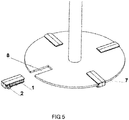
- the stabilizing element can also be embedded (7) as detailed in figure (5 ).
- the case (1) is embedded in the notches (8).
- the invention that is being sought as we have anticipated consists of a part that is coupled by a standard anchoring system of screws or harpoons, or extruded inside a metal piece or other material, flat coupling, to any item of furniture or table, placing it at the base of the same in different support points or in each of its legs.
- Said part consists of a case (1) of rectangular plant open at its base, which is provided with two connecting rods (2 and 3) that come into contact with the supporting surface of the item furniture and move by the pressure of its weight, up and down. This displacement drives the movement of a glide (4) that is cushioned by a damper (5) and a flexor-tension spring (6) located inside the case, which smoothly stabilizes the item of furniture to which it is attached.
Landscapes
- Legs For Furniture In General (AREA)
Abstract
Description
- The present invention describes a furniture stabilizer suitable for uneven floors that prevents its wobbling. The stabilizer comprises connecting rods attached to a sliding glide and this glide is attached to damping means.
- There are different means on the market to adjust in height supporting surfaces of tables and other items of furniture in order to correct their stability in the presence of uneven floors or supporting surfaces and thereby stabilize them, avoiding the annoying "wobbling" effect. The existing systems are mainly manual because they require manual manipulation by means of screwing screws or similar to lengthen or shorten the height of the supporting leg and thereby achieving the levelling of the furniture base. One of the main problems of these systems is that by moving, even slightly, the furniture from the place where it has been stabilized, it is once again necessary to adapt the mechanisms to the new location of the furniture to achieve its stability, because if the floor or supporting surface is not is levelled, the furniture will be adapted to its previous position but not to the current one and it will re-wobble, being necessary new manipulations of the stabilization system. To address this, complicated hydraulics systems of communicating vessels arose, that allow the self-regulation of the furniture legs. Its main problem is the complexity, cost and installation thereof.
- In addition, the systems described in the state of the art are placed on the furniture legs, so for their installation it is necessary to remove the legs.
- Finally, another problem with the stabilization systems for furniture described in the state of the art is that they deteriorate when the items of furniture are dragged horizontally.
- The problem solved by the present invention is a furniture stabilizer without manual manipulation, completely automatically and without using bearings, or screws, using the weight of the item of furniture to be stabilized.
- The solution found by the inventors is a stabilizer comprising a set of connecting rods coupled to a sliding glide and damping means.
- Another problem solved by the invention is to be able to attach the stabilizer to any item of furniture without having to remove the legs, since the stabilizer is attached to the base of the furniture itself or is embedded in the furniture.
- Another problem solved by the invention is to be able to slide the furniture horizontally without deteriorating the levelling system, this aspect being of special interest for heavy furniture.
- The invention consists of a rectangular-shape case (1) with a lower base with open section and inside of which two connecting rods (2 and 3), a glide (4) and damping means are coupled. The damping means adjust the travel speed of the glide.
- In a preferred mode, the damping means comprise a damper (5) and a flexor spring (6).
- When the case is attached to the bottom of the item of furniture or leg, the weight of the item of furniture or element that is placed on top, the pressure exerted by it, causes the connecting rod to move upwards adjusting to the floor in case of unevenness and thus preventing the rolling and stabilizing the item of furniture. The system consists of two connecting rods (2 and 3) located in reverse positions to each other, each of which touches the floor independently of the other occupying the space corresponding to its own support plane with which the protuberances, unevenness or hollows of the supporting surface do not affect the stability that is achieved when those connecting rods pressed by the weight of the item of furniture, in turn press one or more dampers (5) provided or not with flexor-tension spring (6) which horizontally move a glide (4) for each damper. The glide (4) is the element that slides by the pressure of the furniture's weight, cushioned by the damper (5) inside the case (1) itself occupying the space free inside it by the supporting positions adopted by the connecting rods according to the distance to the floor.
Figure 3 shows the connecting rod closed or pressed by the weight of the item of furniture and with the supporting surface at the same level causing its upward movement occupying the entire available internal surface of the case, in this case, the glide (4) it remains fully pressed and without any displacement. Infigure 2 the invention is showed before coming into contact with the floor or supporting surface, the connecting rods (2 and 3) are fully extended and without pressure, which involves the distension of the damper (5) and extension of the spring (6), the glide (4) occupies the position totally to the left. Between the positions offigures 2 and3 all the positions of the connecting rods (2 and 3) are possible, the higher the pressure, the greater the displacement of the glide (4) to the right and left, the greater bending of the spring (6) and the greater damping work to soften the stabilization by the damper (5). - The stabilizer is attached to any item of furniture, without having to disassemble the furniture or legs.
- The stabilizing element will achieve the total stability of the item of furniture to which it is attached by a standard anchoring system of screws or harpoons (9) as detailed in
figure 6 . - The stabilizing element can also be embedded (7) as detailed in
figure (5 ). The case (1) is embedded in the notches (8). -
-
Figure 1 shows an exploded view of the invention. -
Figure 2 shows the invention closed inside the case (1) as seen normally leaving only outward the connecti ng rods (2 and 3) coming into contact with the floor or supporting surface. -
Figure 3 shows the stabilizer object of the invention extended, the connecting rods (2 and 3) have not yet been supported on the floor nor has pressure been exerted on the damper (5) due to the weight of the item of furniture, so damper (5) and spring (6) appear fully extended and the glide occupies the position as far to the left as possible inside the case (1). -
Figure 4 shows the connecti ng rod total ly closed or pressed by the weight of the item of furniture and with the supporting surface at the same level causing its upward movement occupying all the available internal surface of the case, in this case, the 2 glide (4) it remains fully pressed against the damper (5) and without any displacement. -
Figure 5 shows a possible use of the invention in a standard circular base for supporting an item of furniture in which notches (8) are made, wherein the cases (1) are placed embedded (7) in the base itself. -
Figure 6 shows a possible use of the invention by screwing into the base (9) of the case (1) contai ni ng the i nventi on. - The invention that is being sought as we have anticipated consists of a part that is coupled by a standard anchoring system of screws or harpoons, or extruded inside a metal piece or other material, flat coupling, to any item of furniture or table, placing it at the base of the same in different support points or in each of its legs. Said part consists of a case (1) of rectangular plant open at its base, which is provided with two connecting rods (2 and 3) that come into contact with the supporting surface of the item furniture and move by the pressure of its weight, up and down. This displacement drives the movement of a glide (4) that is cushioned by a damper (5) and a flexor-tension spring (6) located inside the case, which smoothly stabilizes the item of furniture to which it is attached.
Claims (4)
- Furniture stabilizer comprising a case (1) inside on which contains two connecting rods (2,3) wherein the connecting rod (2) is fixed to the case (1) and the connecting rod (3) is attached to a glide (4) that moves horizontally inside the case (1) and the displacement of the glide is regulated by damping means.
- Furniture stabilizer according to claim 1, characterised in that the damping means is a damper (5) and a flexor spring (6).
- Furniture stabilizer according to the preceding claims characterised in that it is coupled to the base of an item of furniture by means of screws (9).
- Furniture stabilizer according to claims 1, 2 characterised in that the case (1) is embedded (7) in the notches (8).
Applications Claiming Priority (2)
| Application Number | Priority Date | Filing Date | Title |
|---|---|---|---|
| ES201700012U ES1180161Y (en) | 2016-12-22 | 2016-12-22 | Furniture Stabilizer |
| PCT/ES2017/070836 WO2018115561A1 (en) | 2016-12-22 | 2017-12-20 | Furniture stabiliser |
Publications (4)
| Publication Number | Publication Date |
|---|---|
| EP3560380A1 true EP3560380A1 (en) | 2019-10-30 |
| EP3560380A4 EP3560380A4 (en) | 2020-08-12 |
| EP3560380C0 EP3560380C0 (en) | 2023-11-15 |
| EP3560380B1 EP3560380B1 (en) | 2023-11-15 |
Family
ID=58430407
Family Applications (1)
| Application Number | Title | Priority Date | Filing Date |
|---|---|---|---|
| EP17884878.4A Active EP3560380B1 (en) | 2016-12-22 | 2017-12-20 | Furniture stabiliser |
Country Status (3)
| Country | Link |
|---|---|
| EP (1) | EP3560380B1 (en) |
| ES (2) | ES1180161Y (en) |
| WO (1) | WO2018115561A1 (en) |
Families Citing this family (1)
| Publication number | Priority date | Publication date | Assignee | Title |
|---|---|---|---|---|
| ES1272319Y (en) * | 2021-06-02 | 2021-10-11 | Frances Rafael Ortega | LEVELER FOR TABLES |
Family Cites Families (8)
| Publication number | Priority date | Publication date | Assignee | Title |
|---|---|---|---|---|
| US2793467A (en) * | 1954-03-12 | 1957-05-28 | Albert J Matter | Foot adjusters for enclosed appliances |
| GB959427A (en) * | 1961-09-08 | 1964-06-03 | Artmann Kurt | Improvements in means for increasing the stability of articles of furniture |
| WO2000059344A1 (en) * | 1999-04-01 | 2000-10-12 | Mark Gwynneth | Self stabilising system |
| DE202005005317U1 (en) * | 2005-04-04 | 2005-09-01 | Trendelkamp, Josef | Chair guiding device |
| DE102005024850A1 (en) * | 2005-05-27 | 2006-12-07 | Johan Lefferts | Leveling device for e.g. chair, has lever arm and roller giving movement impulse through movement of supporting unit that adjusts effective length of leg to unevenness of surface, where impulse causes locking of supporting unit |
| NL1036141C (en) * | 2008-10-31 | 2010-05-04 | Bin Innovations Bv | DEVICE FOR STABILIZING OBJECTS ON AN UNDENOUS BACKGROUND. |
| IT1399494B1 (en) * | 2010-04-13 | 2013-04-19 | Brera | HINGE, PARTICULARLY FOR HOUSEHOLD APPLIANCES SUCH AS OVENS, DISHWASHER OR SIMILAR. |
| CN110731639A (en) * | 2019-11-07 | 2020-01-31 | 徐州昇科源信息技术有限公司 | movable seat for VR training |
-
2016
- 2016-12-22 ES ES201700012U patent/ES1180161Y/en active Active
-
2017
- 2017-12-20 EP EP17884878.4A patent/EP3560380B1/en active Active
- 2017-12-20 ES ES17884878T patent/ES2972614T3/en active Active
- 2017-12-20 WO PCT/ES2017/070836 patent/WO2018115561A1/en not_active Ceased
Also Published As
| Publication number | Publication date |
|---|---|
| WO2018115561A1 (en) | 2018-06-28 |
| EP3560380C0 (en) | 2023-11-15 |
| ES2972614T3 (en) | 2024-06-13 |
| EP3560380A4 (en) | 2020-08-12 |
| EP3560380B1 (en) | 2023-11-15 |
| ES1180161U (en) | 2017-04-05 |
| ES1180161Y (en) | 2017-06-26 |
Similar Documents
| Publication | Publication Date | Title |
|---|---|---|
| US9188278B1 (en) | Lifting support structure | |
| US8936306B2 (en) | Composite chair | |
| EP3560380A1 (en) | Furniture stabiliser | |
| CN104006618A (en) | Refrigerator | |
| US20190365096A1 (en) | Desk With Slidable Drawer Assembly | |
| CN202588753U (en) | Multifunctional balance table capable of automatically adjusting angles and height | |
| CN206507551U (en) | Table-top lifting workbench | |
| KR101932958B1 (en) | Array-tool for books | |
| CN209644367U (en) | A kind of household Conjoined dining table chair | |
| CN203709529U (en) | Multifunctional furniture | |
| CN205513436U (en) | Folding student's desk | |
| EP3409143B1 (en) | Leveller for furniture legs | |
| CN204594045U (en) | For refrigerator lower margin assembly and there is its refrigerator | |
| CN203656522U (en) | Multifunctional computer display screen support | |
| CN107581784A (en) | A kind of multifunctional desk | |
| CN201189063Y (en) | Telescopic clothes rack | |
| CN205988089U (en) | Desktop dip angle regulating device and the desk including this desktop dip angle regulating device | |
| CN207821375U (en) | Multifunctional foldable desk | |
| CN201032593Y (en) | Improved structure of thin display support | |
| CN204664799U (en) | Supporting leg | |
| KR200342094Y1 (en) | Height adjustment device of desk and chair for student | |
| CN106175106A (en) | The collapsible magnet attraction height bed-table that a kind of student does one's assignment winter | |
| CN105146907A (en) | Length-adjustable dining table structure | |
| KR100338887B1 (en) | Support for Furniture | |
| CN223773327U (en) | An adjustable height outdoor folding table |
Legal Events
| Date | Code | Title | Description |
|---|---|---|---|
| STAA | Information on the status of an ep patent application or granted ep patent |
Free format text: STATUS: THE INTERNATIONAL PUBLICATION HAS BEEN MADE |
|
| PUAI | Public reference made under article 153(3) epc to a published international application that has entered the european phase |
Free format text: ORIGINAL CODE: 0009012 |
|
| STAA | Information on the status of an ep patent application or granted ep patent |
Free format text: STATUS: REQUEST FOR EXAMINATION WAS MADE |
|
| 17P | Request for examination filed |
Effective date: 20190722 |
|
| AK | Designated contracting states |
Kind code of ref document: A1 Designated state(s): AL AT BE BG CH CY CZ DE DK EE ES FI FR GB GR HR HU IE IS IT LI LT LU LV MC MK MT NL NO PL PT RO RS SE SI SK SM TR |
|
| AX | Request for extension of the european patent |
Extension state: BA ME |
|
| DAV | Request for validation of the european patent (deleted) | ||
| DAX | Request for extension of the european patent (deleted) | ||
| A4 | Supplementary search report drawn up and despatched |
Effective date: 20200709 |
|
| RIC1 | Information provided on ipc code assigned before grant |
Ipc: A47B 91/16 20060101AFI20200704BHEP |
|
| STAA | Information on the status of an ep patent application or granted ep patent |
Free format text: STATUS: EXAMINATION IS IN PROGRESS |
|
| 17Q | First examination report despatched |
Effective date: 20210630 |
|
| GRAP | Despatch of communication of intention to grant a patent |
Free format text: ORIGINAL CODE: EPIDOSNIGR1 |
|
| STAA | Information on the status of an ep patent application or granted ep patent |
Free format text: STATUS: GRANT OF PATENT IS INTENDED |
|
| INTG | Intention to grant announced |
Effective date: 20230605 |
|
| GRAS | Grant fee paid |
Free format text: ORIGINAL CODE: EPIDOSNIGR3 |
|
| GRAA | (expected) grant |
Free format text: ORIGINAL CODE: 0009210 |
|
| STAA | Information on the status of an ep patent application or granted ep patent |
Free format text: STATUS: THE PATENT HAS BEEN GRANTED |
|
| AK | Designated contracting states |
Kind code of ref document: B1 Designated state(s): AL AT BE BG CH CY CZ DE DK EE ES FI FR GB GR HR HU IE IS IT LI LT LU LV MC MK MT NL NO PL PT RO RS SE SI SK SM TR |
|
| REG | Reference to a national code |
Ref country code: CH Ref legal event code: EP Ref country code: GB Ref legal event code: FG4D |
|
| REG | Reference to a national code |
Ref country code: DE Ref legal event code: R096 Ref document number: 602017076624 Country of ref document: DE |
|
| REG | Reference to a national code |
Ref country code: IE Ref legal event code: FG4D |
|
| U01 | Request for unitary effect filed |
Effective date: 20231212 |
|
| U07 | Unitary effect registered |
Designated state(s): AT BE BG DE DK EE FI FR IT LT LU LV MT NL PT SE SI Effective date: 20240108 |
|
| PG25 | Lapsed in a contracting state [announced via postgrant information from national office to epo] |
Ref country code: GR Free format text: LAPSE BECAUSE OF FAILURE TO SUBMIT A TRANSLATION OF THE DESCRIPTION OR TO PAY THE FEE WITHIN THE PRESCRIBED TIME-LIMIT Effective date: 20240216 |
|
| PG25 | Lapsed in a contracting state [announced via postgrant information from national office to epo] |
Ref country code: IS Free format text: LAPSE BECAUSE OF FAILURE TO SUBMIT A TRANSLATION OF THE DESCRIPTION OR TO PAY THE FEE WITHIN THE PRESCRIBED TIME-LIMIT Effective date: 20240315 |
|
| PG25 | Lapsed in a contracting state [announced via postgrant information from national office to epo] |
Ref country code: IS Free format text: LAPSE BECAUSE OF FAILURE TO SUBMIT A TRANSLATION OF THE DESCRIPTION OR TO PAY THE FEE WITHIN THE PRESCRIBED TIME-LIMIT Effective date: 20240315 Ref country code: GR Free format text: LAPSE BECAUSE OF FAILURE TO SUBMIT A TRANSLATION OF THE DESCRIPTION OR TO PAY THE FEE WITHIN THE PRESCRIBED TIME-LIMIT Effective date: 20240216 |
|
| U20 | Renewal fee for the european patent with unitary effect paid |
Year of fee payment: 7 Effective date: 20240408 |
|
| PG25 | Lapsed in a contracting state [announced via postgrant information from national office to epo] |
Ref country code: RS Free format text: LAPSE BECAUSE OF FAILURE TO SUBMIT A TRANSLATION OF THE DESCRIPTION OR TO PAY THE FEE WITHIN THE PRESCRIBED TIME-LIMIT Effective date: 20231115 Ref country code: PL Free format text: LAPSE BECAUSE OF FAILURE TO SUBMIT A TRANSLATION OF THE DESCRIPTION OR TO PAY THE FEE WITHIN THE PRESCRIBED TIME-LIMIT Effective date: 20231115 Ref country code: NO Free format text: LAPSE BECAUSE OF FAILURE TO SUBMIT A TRANSLATION OF THE DESCRIPTION OR TO PAY THE FEE WITHIN THE PRESCRIBED TIME-LIMIT Effective date: 20240215 Ref country code: HR Free format text: LAPSE BECAUSE OF FAILURE TO SUBMIT A TRANSLATION OF THE DESCRIPTION OR TO PAY THE FEE WITHIN THE PRESCRIBED TIME-LIMIT Effective date: 20231115 |
|
| REG | Reference to a national code |
Ref country code: ES Ref legal event code: FG2A Ref document number: 2972614 Country of ref document: ES Kind code of ref document: T3 Effective date: 20240613 |
|
| PG25 | Lapsed in a contracting state [announced via postgrant information from national office to epo] |
Ref country code: CZ Free format text: LAPSE BECAUSE OF FAILURE TO SUBMIT A TRANSLATION OF THE DESCRIPTION OR TO PAY THE FEE WITHIN THE PRESCRIBED TIME-LIMIT Effective date: 20231115 |
|
| PG25 | Lapsed in a contracting state [announced via postgrant information from national office to epo] |
Ref country code: SK Free format text: LAPSE BECAUSE OF FAILURE TO SUBMIT A TRANSLATION OF THE DESCRIPTION OR TO PAY THE FEE WITHIN THE PRESCRIBED TIME-LIMIT Effective date: 20231115 |
|
| PG25 | Lapsed in a contracting state [announced via postgrant information from national office to epo] |
Ref country code: SM Free format text: LAPSE BECAUSE OF FAILURE TO SUBMIT A TRANSLATION OF THE DESCRIPTION OR TO PAY THE FEE WITHIN THE PRESCRIBED TIME-LIMIT Effective date: 20231115 Ref country code: SK Free format text: LAPSE BECAUSE OF FAILURE TO SUBMIT A TRANSLATION OF THE DESCRIPTION OR TO PAY THE FEE WITHIN THE PRESCRIBED TIME-LIMIT Effective date: 20231115 Ref country code: RO Free format text: LAPSE BECAUSE OF FAILURE TO SUBMIT A TRANSLATION OF THE DESCRIPTION OR TO PAY THE FEE WITHIN THE PRESCRIBED TIME-LIMIT Effective date: 20231115 Ref country code: CZ Free format text: LAPSE BECAUSE OF FAILURE TO SUBMIT A TRANSLATION OF THE DESCRIPTION OR TO PAY THE FEE WITHIN THE PRESCRIBED TIME-LIMIT Effective date: 20231115 |
|
| REG | Reference to a national code |
Ref country code: CH Ref legal event code: PL |
|
| REG | Reference to a national code |
Ref country code: DE Ref legal event code: R097 Ref document number: 602017076624 Country of ref document: DE |
|
| PG25 | Lapsed in a contracting state [announced via postgrant information from national office to epo] |
Ref country code: MC Free format text: LAPSE BECAUSE OF FAILURE TO SUBMIT A TRANSLATION OF THE DESCRIPTION OR TO PAY THE FEE WITHIN THE PRESCRIBED TIME-LIMIT Effective date: 20231115 |
|
| PG25 | Lapsed in a contracting state [announced via postgrant information from national office to epo] |
Ref country code: MC Free format text: LAPSE BECAUSE OF FAILURE TO SUBMIT A TRANSLATION OF THE DESCRIPTION OR TO PAY THE FEE WITHIN THE PRESCRIBED TIME-LIMIT Effective date: 20231115 |
|
| PLBE | No opposition filed within time limit |
Free format text: ORIGINAL CODE: 0009261 |
|
| STAA | Information on the status of an ep patent application or granted ep patent |
Free format text: STATUS: NO OPPOSITION FILED WITHIN TIME LIMIT |
|
| REG | Reference to a national code |
Ref country code: IE Ref legal event code: MM4A |
|
| PG25 | Lapsed in a contracting state [announced via postgrant information from national office to epo] |
Ref country code: IE Free format text: LAPSE BECAUSE OF NON-PAYMENT OF DUE FEES Effective date: 20231220 |
|
| PG25 | Lapsed in a contracting state [announced via postgrant information from national office to epo] |
Ref country code: CH Free format text: LAPSE BECAUSE OF NON-PAYMENT OF DUE FEES Effective date: 20231231 |
|
| 26N | No opposition filed |
Effective date: 20240819 |
|
| GBPC | Gb: european patent ceased through non-payment of renewal fee |
Effective date: 20240215 |
|
| PG25 | Lapsed in a contracting state [announced via postgrant information from national office to epo] |
Ref country code: IE Free format text: LAPSE BECAUSE OF NON-PAYMENT OF DUE FEES Effective date: 20231220 Ref country code: CH Free format text: LAPSE BECAUSE OF NON-PAYMENT OF DUE FEES Effective date: 20231231 |
|
| PG25 | Lapsed in a contracting state [announced via postgrant information from national office to epo] |
Ref country code: GB Free format text: LAPSE BECAUSE OF NON-PAYMENT OF DUE FEES Effective date: 20240215 |
|
| U20 | Renewal fee for the european patent with unitary effect paid |
Year of fee payment: 8 Effective date: 20241226 |
|
| PG25 | Lapsed in a contracting state [announced via postgrant information from national office to epo] |
Ref country code: GB Free format text: LAPSE BECAUSE OF NON-PAYMENT OF DUE FEES Effective date: 20240215 |
|
| PGFP | Annual fee paid to national office [announced via postgrant information from national office to epo] |
Ref country code: ES Payment date: 20250227 Year of fee payment: 8 |
|
| PG25 | Lapsed in a contracting state [announced via postgrant information from national office to epo] |
Ref country code: CY Free format text: LAPSE BECAUSE OF FAILURE TO SUBMIT A TRANSLATION OF THE DESCRIPTION OR TO PAY THE FEE WITHIN THE PRESCRIBED TIME-LIMIT; INVALID AB INITIO Effective date: 20171220 |
|
| PG25 | Lapsed in a contracting state [announced via postgrant information from national office to epo] |
Ref country code: HU Free format text: LAPSE BECAUSE OF FAILURE TO SUBMIT A TRANSLATION OF THE DESCRIPTION OR TO PAY THE FEE WITHIN THE PRESCRIBED TIME-LIMIT; INVALID AB INITIO Effective date: 20171220 |
|
| PG25 | Lapsed in a contracting state [announced via postgrant information from national office to epo] |
Ref country code: TR Free format text: LAPSE BECAUSE OF FAILURE TO SUBMIT A TRANSLATION OF THE DESCRIPTION OR TO PAY THE FEE WITHIN THE PRESCRIBED TIME-LIMIT Effective date: 20231115 |
|
| U20 | Renewal fee for the european patent with unitary effect paid |
Year of fee payment: 9 Effective date: 20251231 |