EP3560108B1 - Distributed mimo and/or transmit diversity in a cloud-ran system - Google Patents
Distributed mimo and/or transmit diversity in a cloud-ran system Download PDFInfo
- Publication number
- EP3560108B1 EP3560108B1 EP17884470.0A EP17884470A EP3560108B1 EP 3560108 B1 EP3560108 B1 EP 3560108B1 EP 17884470 A EP17884470 A EP 17884470A EP 3560108 B1 EP3560108 B1 EP 3560108B1
- Authority
- EP
- European Patent Office
- Prior art keywords
- user equipment
- antenna ports
- items
- transmit
- downlink transmission
- Prior art date
- Legal status (The legal status is an assumption and is not a legal conclusion. Google has not performed a legal analysis and makes no representation as to the accuracy of the status listed.)
- Active
Links
Images



Classifications
-
- H—ELECTRICITY
- H04—ELECTRIC COMMUNICATION TECHNIQUE
- H04B—TRANSMISSION
- H04B7/00—Radio transmission systems, i.e. using radiation field
- H04B7/02—Diversity systems; Multi-antenna system, i.e. transmission or reception using multiple antennas
- H04B7/022—Site diversity; Macro-diversity
-
- H—ELECTRICITY
- H04—ELECTRIC COMMUNICATION TECHNIQUE
- H04B—TRANSMISSION
- H04B7/00—Radio transmission systems, i.e. using radiation field
- H04B7/02—Diversity systems; Multi-antenna system, i.e. transmission or reception using multiple antennas
- H04B7/04—Diversity systems; Multi-antenna system, i.e. transmission or reception using multiple antennas using two or more spaced independent antennas
- H04B7/0413—MIMO systems
- H04B7/0426—Power distribution
- H04B7/043—Power distribution using best eigenmode, e.g. beam forming or beam steering
-
- H—ELECTRICITY
- H04—ELECTRIC COMMUNICATION TECHNIQUE
- H04B—TRANSMISSION
- H04B7/00—Radio transmission systems, i.e. using radiation field
- H04B7/02—Diversity systems; Multi-antenna system, i.e. transmission or reception using multiple antennas
- H04B7/04—Diversity systems; Multi-antenna system, i.e. transmission or reception using multiple antennas using two or more spaced independent antennas
- H04B7/0413—MIMO systems
- H04B7/0456—Selection of precoding matrices or codebooks, e.g. using matrices antenna weighting
- H04B7/046—Selection of precoding matrices or codebooks, e.g. using matrices antenna weighting taking physical layer constraints into account
- H04B7/0465—Selection of precoding matrices or codebooks, e.g. using matrices antenna weighting taking physical layer constraints into account taking power constraints at power amplifier or emission constraints, e.g. constant modulus, into account
-
- H—ELECTRICITY
- H04—ELECTRIC COMMUNICATION TECHNIQUE
- H04B—TRANSMISSION
- H04B7/00—Radio transmission systems, i.e. using radiation field
- H04B7/02—Diversity systems; Multi-antenna system, i.e. transmission or reception using multiple antennas
- H04B7/04—Diversity systems; Multi-antenna system, i.e. transmission or reception using multiple antennas using two or more spaced independent antennas
- H04B7/0413—MIMO systems
- H04B7/0456—Selection of precoding matrices or codebooks, e.g. using matrices antenna weighting
- H04B7/0478—Special codebook structures directed to feedback optimisation
- H04B7/0481—Special codebook structures directed to feedback optimisation using subset selection of codebooks
-
- H—ELECTRICITY
- H04—ELECTRIC COMMUNICATION TECHNIQUE
- H04L—TRANSMISSION OF DIGITAL INFORMATION, e.g. TELEGRAPHIC COMMUNICATION
- H04L1/00—Arrangements for detecting or preventing errors in the information received
- H04L1/02—Arrangements for detecting or preventing errors in the information received by diversity reception
- H04L1/06—Arrangements for detecting or preventing errors in the information received by diversity reception using space diversity
- H04L1/0606—Space-frequency coding
-
- H—ELECTRICITY
- H04—ELECTRIC COMMUNICATION TECHNIQUE
- H04L—TRANSMISSION OF DIGITAL INFORMATION, e.g. TELEGRAPHIC COMMUNICATION
- H04L27/00—Modulated-carrier systems
- H04L27/26—Systems using multi-frequency codes
- H04L27/2601—Multicarrier modulation systems
- H04L27/2647—Arrangements specific to the receiver only
- H04L27/2655—Synchronisation arrangements
- H04L27/2668—Details of algorithms
- H04L27/2673—Details of algorithms characterised by synchronisation parameters
- H04L27/2675—Pilot or known symbols
-
- H—ELECTRICITY
- H04—ELECTRIC COMMUNICATION TECHNIQUE
- H04L—TRANSMISSION OF DIGITAL INFORMATION, e.g. TELEGRAPHIC COMMUNICATION
- H04L5/00—Arrangements affording multiple use of the transmission path
- H04L5/003—Arrangements for allocating sub-channels of the transmission path
- H04L5/0032—Distributed allocation, i.e. involving a plurality of allocating devices, each making partial allocation
- H04L5/0035—Resource allocation in a cooperative multipoint environment
-
- H—ELECTRICITY
- H04—ELECTRIC COMMUNICATION TECHNIQUE
- H04L—TRANSMISSION OF DIGITAL INFORMATION, e.g. TELEGRAPHIC COMMUNICATION
- H04L5/00—Arrangements affording multiple use of the transmission path
- H04L5/003—Arrangements for allocating sub-channels of the transmission path
- H04L5/0058—Allocation criteria
- H04L5/0073—Allocation arrangements that take into account other cell interferences
-
- H—ELECTRICITY
- H04—ELECTRIC COMMUNICATION TECHNIQUE
- H04W—WIRELESS COMMUNICATION NETWORKS
- H04W72/00—Local resource management
- H04W72/20—Control channels or signalling for resource management
- H04W72/23—Control channels or signalling for resource management in the downlink direction of a wireless link, i.e. towards a terminal
-
- G—PHYSICS
- G06—COMPUTING OR CALCULATING; COUNTING
- G06F—ELECTRIC DIGITAL DATA PROCESSING
- G06F17/00—Digital computing or data processing equipment or methods, specially adapted for specific functions
- G06F17/10—Complex mathematical operations
- G06F17/16—Matrix or vector computation, e.g. matrix-matrix or matrix-vector multiplication, matrix factorization
-
- H—ELECTRICITY
- H04—ELECTRIC COMMUNICATION TECHNIQUE
- H04L—TRANSMISSION OF DIGITAL INFORMATION, e.g. TELEGRAPHIC COMMUNICATION
- H04L5/00—Arrangements affording multiple use of the transmission path
Definitions
- LTE Long Term Evolution
- 3GPP 3rd Generation Partnership Project
- LTE supports multiple downlink transmission modes, most of which support downlink transmission using multiple antennas. Indeed, support for the use of multiple antennas is a core feature of LTE.
- these multiple-antenna LTE downlink transmission modes are performed using precoding.
- Precoding performs a matrix transformation of v sequences of symbols x into p sequences of symbols y, where v corresponds to the number of layers being used and p corresponds to the number of transmit antenna ports being used. The number of layers being used is also referred to as the "transmission rank.”
- One or two data code words are transmitted per layer.
- a precoder matrix W is used for precoding.
- the multiple-antenna LTE downlink transmission modes that employ precoding use either transmit diversity or spatial multiplexing.
- transmit diversity for example, LTE downlink transmission mode 2
- a single sequence of symbols is transmitted from multiple antennas.
- a single code word is sent.
- the precoding is done using a precoding matrix W specified by the LTE standards that is based on Space-Frequency Block Coding (SFBC).
- SFBC Space-Frequency Block Coding
- the precoding is done using a precoding matrix W specified by the LTE standards that is based on SFBC and Frequency-Shift Transmit Diversity (FSTD)
- a codebook is a table that comprises several predefined precoder matrices W that can be selected for use in precoding.
- CS-RS Cell specific reference symbols
- the UE uses the CS-RSs to generate channel state information (CSI) that is fed back to the eNodeB.
- This CSI includes a rank indicator (RI) and a precoder matrix indicator (PMI).
- RI indicates how many layers should be used for the current channel conditions
- PMI indicates which one of the predefined precoder matrices included in the codebook should be used for the current channel conditions.
- the precoding schemes used with such multiple-antenna LTE downlink transmission modes are not designed for use with a specific base station or radio access network configuration.
- the present invention relates to a method and system as defined by the independent claims 1 and 7, respectively.
- FIG. 1 is a block diagram illustrating one exemplary embodiment of a radio access network (RAN) 100 in which multiple-antenna downlink transmission modes can be implemented in a distributed manner.
- the RAN 100 is deployed at a site 102 to provide wireless coverage and capacity for one or more wireless network operators.
- the site 102 may be, for example, a building or campus or other grouping of buildings (used, for example, by one or more businesses, government, other enterprise entities) or some other public venue (such as a hotel, resort, amusement park, hospital, shopping center, airport, university campus, arena, or an outdoor area such as a ski area, stadium or a densely-populated downtown area).
- the RAN 100 at the site 102 is implemented at least in part using a point-to-multipoint distributed base station architecture that employs at least one central controller 104 and multiple radio points (RPs) 106.
- Each RP 106 includes or is coupled to one or more antennas 108 via which downlink RF signals are radiated to user equipment 110 and via which uplink RF signals transmitted by user equipment (UE) 110 are received.
- UE user equipment
- each RP 106 comprises two antennas 108.
- Each RP 106 can include or be coupled to a different number of antennas 108.
- the RAN 100 is coupled to the core network 112 of each wireless network operator over an appropriate back-haul.
- the Internet 114 is used for back-haul between the RAN 100 and each core network 112.
- the back-haul can be implemented in other ways.
- LTE Long Term Evolution
- eNodeB eNodeB
- eNB LTE Evolved Node B
- each core network 112 is implemented as an Evolved Packet Core (EPC) 112 comprising standard LTE EPC network elements such as, for example, a mobility management entity (MME) and a Serving Gateway (SGW) and, optionally, a Home eNodeB gateway (HeNB GW) and a Security Gateway (SeGW) (all of which are not shown in FIG. 1 ).
- EPC Evolved Packet Core
- each controller 104 communicates with the MME and SGW in the EPC core network 112 using the LTE S1 interface and communicates with other eNodeBs using the LTE X2 interface.
- the controller 104 communicates with an outdoor macro eNodeB (not shown) via the LTE X2 interface.
- the controller 104 and the radio points 106 can be implemented to use an air interface that supports one or more of frequency-division duplexing (FDD) and/or time-division duplexing (TDD). Also, the controller 104 and the radio points 106 can be implemented to use an air interface that supports one or more of the multiple-input-multiple-output (MIMO), single-input-single-output (SISO), single-input-multiple-output (SIMO), multiple-input-single-output (MISO), and/or beam forming schemes. For example, the controller 104 and the radio points 106 can implement one or more of the LTE transmission modes. Moreover, the controller 104 and/or the radio points 106 can be configured to support multiple air interfaces and/or to support multiple wireless operators.
- FDD frequency-division duplexing
- TDD time-division duplexing
- MIMO multiple-input-multiple-output
- SISO single-input-single-out
- the front-haul that communicatively couples each controller 104 to the one or more RPs 106 is implemented using a standard ETHERNET network 118.
- ETHERNET network 118 the front-haul between the controllers 104 and RPs 106 can be implemented in other ways.
- one or more nodes in a RAN perform analog radio frequency (RF) functions for the air interface as well as digital Layer 1, Layer 2, and Layer 3 (of the Open Systems Interconnection (OSI) model) functions for the air interface.
- RF radio frequency
- OSI Open Systems Interconnection
- each controller 104 includes one or more baseband modems (BBMs) (or other units) 120 that perform digital Layer-3, Layer-2, and Layer-1 processing for the LTE air interface
- each RP 106 includes (optionally) one or more Layer-1 units (not shown) that implements any Layer-1 processing for the air interface that is not performed in the controller 104 and one or more radio frequency (RF) circuits (not shown) that implement the RF front-end functions for the air interface and the one or more antennas 108 associated with that RP 106.
- BFMs baseband modems
- RF radio frequency
- the baseband modems 120 in the controllers 104 can be configured to perform all of the digital Layer-3, Layer-2, and Layer-1 processing for the air interface, while the RPs 106 (specifically, the RF circuits) implement only the RF functions for the air interface and the antennas 108 associated with each RP 106.
- IQ data representing time-domain symbols for the air interface is communicated between the controller 104 and the RPs 106. Communicating such time-domain IQ data typically requires a relatively high data rate front haul. This approach (communicating time-domain IQ data over the front haul) is suitable for those implementations where the front-haul ETHERNET network 118 is able to deliver the required high data rate.
- the front-haul ETHERNET network 118 is not able to deliver the data rate needed to front haul time-domain IQ data (for example, where the front-haul is implemented using typical enterprise-grade ETHERNET networks), this issue can be addressed by communicating IQ data representing frequency-domain symbols for the air interface between the CUs 104 and the RPs 106.
- This frequency-domain IQ data represents the symbols in the frequency domain before the inverse fast Fourier transform (IFFT) is performed.
- IFFT inverse fast Fourier transform
- the time-domain IQ data can be generated by quantizing the IQ data representing the frequency-domain symbols without guard band zeroes or any cyclic prefix and communicating the resulting compressed, quantized frequency-domain IQ data over the front-haul ETHERNET network 118. Additional details regarding this approach to communicating frequency-domain IQ data can be found in US Patent Application Serial No. 13/762,283, filed on February 7, 2013 , and titled "RADIO ACCESS NETWORKS,”.
- the baseband modems 120 in each controller 104 can be configured to perform all of the digital Layer-3, Layer-2, and Layer-1 processing for the air interface except for the inverse fast Fourier transform (IFFT) in the downlink and the fast Fourier transform (FFT) in the uplink.
- IFFT inverse fast Fourier transform
- FFT fast Fourier transform
- the Layer-1 functions in each RP 106 can be configured to implement the digital Layer-1 processing for the air interface that is not performed in the controller 104 (that is, the IFFT in the downlink and the FFT in the uplink).
- Data can be front-hauled between the controllers 104 and RPs 106 in other ways (for example, using front-haul interfaces and techniques specified in the Common Public Radio Interface (CPRI) and/or Open Base Station Architecture Initiative (OBSAI) family of specifications).
- CPRI Common Public Radio Interface
- OBSAI Open Base Station Architecture Initiative
- Each baseband modem 120 in the controller 104 provides the capacity of a single cellular sector.
- traditional base stations for example, with traditional small cell or distributed base stations
- the capacity provided by each baseband modem creates a separate cell, having a separate physical cell identifier associated with that cell and transmitting separate control and reference signals associated with that cell.
- the capacity provided by several baseband modems for example, in the form of several small cell base stations
- multiple overlapping cells are created with interference at cell borders. This happens even when there is a traditional central service controller that is coordinating multiple small cell base stations.
- the service controller can assist with network configuration and optimization, handovers, and backhaul aggregation, but does not address the issue that each baseband modem forms a separate, standalone cell and interferes with its neighboring separate, standalone cells.
- the signal quality in these overlap areas can drop significantly, reducing data speeds and impairing voice quality.
- creating multiple separate cells generates frequent handovers, for example, in the form of "ping-ponging" of stationery users in border areas, or as users move about the site. This further degrades the user experience and creates the potential for handover failures.
- each controller 104 includes a central coordinator 128 that performs central resource block scheduling for all of the baseband modems 120 across all of the RPs 106 and all of the user equipment 110 associated with those baseband modems 120.
- Frequency reuse techniques can be used to create virtual sectors within the single super cell 126, with different baseband modems 120 providing capacity to each of the virtual sectors.
- the central coordinator 128 can also serve as an aggregation point for data that is transmitted and received using multiple baseband modems 120 and multiple RPs 106.
- the central coordinator 128 can schedule multiple RPs 106 to jointly transmit to an individual UE 110, helping overcome an interfering macro signal without having to boost RP transmit power such that it would interfere with the macro. Similarly, the central coordinator 128 can schedule multiple RPs 106 to jointly receive uplink transmissions from a single UE 110, which are then combined at the controller 104 (either in the baseband modem 120 or in the central coordinator 128). This inter-RP uplink combining enables the UE 110 to transmit at a lower power, reducing its interference on the macro uplink. Additional details regarding the creation of such a super cell 126 can be found in US Patent Application Serial No. 13/762,283 , mentioned above.
- the baseband modems 120 and the central coordinator 128 in each controller 104 can be implemented in software or firmware executing on one or more suitable programmable processors.
- the baseband modems 120 and the central coordinator 128 in each controller 104 (or portions thereof) can be implemented in other ways (for example, in a field programmable gate array (FPGA), application specific integrated circuit (ASIC), etc.).
- the baseband modem 120 and the central coordinator 128 in each controller 104 can be implemented in other ways.
- one or more Layer-1 units (not shown) in each RP 106 can be implemented in software or firmware executing on one or more suitable programmable processors.
- the one or more Layer-1 units in each RP 106 (or portions thereof) can be implemented in other ways (for example, in a field programmable gate array (FPGA), application specific integrated circuit (ASIC), etc.).
- the one or more RF circuits in each RP 106 can be implemented using one or more RF integrated circuits (RFICs) and/or discrete components.
- RFICs RF integrated circuits
- the Layer-1 units and RF circuit in each RP 106 can be implemented in other ways.
- the common, single super cell 126 is created using baseband modems 120 from multiple controllers 104, where resource block scheduling is performed across all of the baseband modems 120 from the multiple controllers 104 (for example, using one or more of the central coordinators 128 in the controllers 104 and/or using a separate global coordinator).
- FIG. 1 makes use of a central coordinator 128 to create a super cell 126 as described above, it is to be understood that other embodiments are implemented in other ways (for example, where the controllers 104 do not include such a central coordinator 128 and instead such coordination functions are incorporated into each baseband modem 120).
- the controllers 104 may also include certain MME functionality (not shown) and SGW functionality (not shown), thus allowing traffic to flow directly between UE 110 and a destination node on the Internet 114 or on a local network at the site 102 without traversing an operator's core network 112.
- a management system 130 is communicatively coupled to the controllers 104 and RPs 106, for example, via the Internet 114 and ETHERNET network 118 (in the case of the RPs 106).
- the management system 130 communicates with the various elements of the RAN 100 using the Internet 114 and the ETHERNET network 118. Also, in some implementations, the management system 130 sends and receives management communications to and from the controllers 104, each of which in turn forwards relevant management communications to and from the RPs 106.
- the controller 104 and RPs 106 together are used to implement an LTE eNodeB.
- the controller 104 and RPs 106 are configured to implement the multiple-antenna LTE downlink transmission modes in a distributed manner.
- the multiple-antenna LTE downlink transmission modes are implemented in a "distributed" manner in the sense that the multiple antennas for a given logical eNodeB are not co-located with each other and, instead, are deployed using radio points 106 that are located remotely from each other.
- Each downlink transmission mode makes use of one or more "antenna ports,” which are logical entities that are distinguished by their reference signal sequences.
- each multiple-antenna downlink transmission mode makes use of multiple antenna ports.
- each antenna port as assigned to a respective one or more antenna 108 in the RAN 100.
- each antenna port can be assigned one of four antenna port indices (0, 1, 2, or 3).
- Each of the distributed antennas 108 in the RAN 100 can also be assigned one of four antenna indices (0, 1, 2, or 3), where each antenna index corresponds to a respective antenna port index for that transmission mode.
- the RPs 106 (and associated antennas 108) are physically arranged within the coverage area of the RAN 100 so that four adjacent antennas 108 will be assigned four different antenna indices. Also, the antennas 108 are assigned and arranged to minimize the number of antennas 108 with the same antenna index that are physically near each other.
- each RP 106 includes or is coupled to two antennas 108.
- each RP 106 is assigned a respective one of two RP indices (0 or 1), where the RPs assigned the RP index 0 are labelled "RP 0" and where the RPs assigned the RP index 1 are labelled as "RP 1.”
- the two antennas 108 associated with each RP 0 are assigned antenna indices 0 and 1, respectively, (and are labelled "antenna 0" and “antenna 1,” respectively), and the two antennas 108 associated with each RP 1 are assigned antenna indices 2 and 3, respectively, (and are labelled “antenna 2" and “antenna 3,” respectively).
- adjacent pairs of RPs 106 are assigned different RP indices so that the associated antennas 108 are assigned four different antenna
- the RPs 106 are arranged in a generally "checkerboard" pattern with RPs 106 assigned the first RP index alternating in both of two directions with RPs 106 assigned the second RP index.
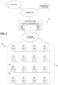
- FIG. 2 illustrates another example where each RP 106 includes or is coupled to a single antenna 108.
- each RP 106 is assigned a respective one of four RP indices (0, 1, 2, or 3), where the RPs 106 assigned the RP index 0 are labelled as "RP 0," the RPs 106 assigned the RP index 1 are labelled as "RP 1," the RPs 106 assigned the RP index 2 are labelled as "RP 2,” and the RPs 106 assigned the RP index 3 are labelled as "RP 3.”
- Each antenna 108 associated with each RP 0 is assigned antenna index 0 (and is labelled “antenna 0")
- each antenna 108 associated with each RP 1 is assigned antenna index 1 (and is labelled “antenna 1")
- each antenna 108 associated with each RP 2 is assigned antenna index 2 (and is labelled “antenna 2")
- each antenna 108 associated with each RP 3 is assigned antenna index 3 (and is labelled "antenna 3”
- These assignments can be made manually (for example, using the management system 130).
- receive power measurements of user-equipment transmissions are made at each RP 106 for many user-equipment positions. These power measurements are used to determine the antenna and radio point assignments.
- the controller 104 and the RPs 106 are made aware of the various assignments.
- a "simulcast group" for a given UE 110 is the set of RPs 106 and associated antennas 108 that are used to transmit downlink user data to that UE 110.
- the cell-specific reference symbols are radiated from all of the antennas 108 and RPs 106 in the RAN 100.
- the rank indicator (RI) that is, how many layers should be used for the current channel conditions
- the precoding matrix indicator (PMI) that is, which predefined precoder matrix included in the codebook should be used for the current channel conditions
- the user-plane data for each UE 110 is radiated from less than all of the antennas 108 and RPs 106. That is, the user-plane data for each UE 110 is only radiated from the antennas 108 and RPs 106 that are in that UE's simulcast group. This can result in bias when the user-plane transmissions are demodulated and decoded by each UE 110. This bias results from the difference between the composite RF channel under which each UE 110 receives the cell-specific reference symbols and the composite RF channel under which each UE 110 receives the user-plane transmissions.
- reuse refers to situations where two or more UEs 110 receive user-plane transmissions using the same resource elements in the same cell.
- one approach to supporting such reuse is to define simulcast groups that include the antennas 108 (and associated RPs 106) assigned to all of the antenna ports used by that downlink transmission mode. That is, where this type of reuse is being used with a downlink transmission mode that uses four antenna ports, each simulcast group for a UE 110 in reuse includes antennas 108 (and associated RPs 106) that are assigned to all four antenna ports.
- reuse can be used with a downlink transmission mode that uses four antenna ports where a first UE 110 is provided wireless service by a first simulcast group that includes a first pair of RPs 0 and 1 (and associated four antennas 0, 1, 2, and 3) and a second UE 110 is provided wireless service by a second simulcast group that includes a second pair of RPs 0 and 1 (and associated four antennas 0, 1, 2, and 3).
- Each UE is sufficiently physically separated from the antennas 108 of the other UE's simulcast group to enable such resource-element reuse.
- This first approach to reuse is also referred to here as "far" reuse.
- simulcast groups that include antennas 108 (and associated RPs 106) assigned to less than all of the antenna ports used by the multiple-antenna downlink transmission mode. For example, where reuse is being used with a downlink transmission mode that uses four antenna ports, each simulcast group can include physical antennas 108 (and associated RPs 106) assigned to two of the antenna ports.
- reuse can be used with a downlink transmission mode that uses four antenna ports where a first UE 110 is provided wireless service by a first simulcast group that includes a first RP 0 (and associated two antennas 0 and 1) and a second UE 110 is provided wireless service by a second simulcast group that includes RP 1 (and associated two antennas 2, and 3).
- Each UE 110 is sufficiently physically separated from the antennas 108 of the other UE's simulcast group to enable such resource-element reuse.
- This second approach to reuse is also referred to here as "near" reuse.
- near reuse can result in bias when the user-plane transmissions are demodulated and decoded by each UE 110. This bias results from the difference between the composite RF channel under which each UE 110 receives the cell-specific reference symbols and the composite RF channel under which each UE 110 receives the user-plane transmissions.
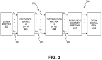
- FIG. 3 is a block diagram illustrating an exemplary embodiment of a scheme for addressing this issue with bias.
- the exemplary embodiment shown in FIG. 3 is described here as being implemented using the RAN 100 shown in FIG. 1 , though it is to be understood that other embodiments can be implemented in other ways (for example, using the example shown in FIG. 2 ).
- the scheme shown in FIG. 3 can implemented in the controller 104, the radio point 106, or both the controller 104 and the radio point 106. More specifically, the processing described here can be implemented at least in part in software or firmware (for example, by programming a programmable processor such as a general-purpose microprocessor or using a field programmable gate array (FPGA)). The processing can also be implemented at least in part in other ways (for example, implemented in discrete circuitry or using an application specification integrated circuit (ASIC)).
- ASIC application specification integrated circuit
- v sequences of symbols x 301 are received from the layer mapper 302 that performs standard LTE layer mapping (if necessary) for the selected LTE downlink transmission mode, where v corresponds to the number of layers being used.
- Standard LTE precoding of the sequences of symbols x 301 is performed for the selected LTE downlink transmission mode.
- This standard LTE precoding is performed using a precoder matrix W 304.
- the precoder matrix W 304 is a p ⁇ v matrix, where p corresponds to the number of transmit antenna ports being used for the selected LTE downlink transmission mode and again v corresponds to the number of layers being used.
- the result of performing the standard LTE precoding is p sequences of symbols y 303.
- a linear (matrix) transformation is performed on the resulting sequence of symbols y 303 resulting from the standard LTE precoding.
- This second matrix transformation is performed using a second matrix G 306.
- This second matrix transformation is also referred to here as the "distribution” transformation, and the second matrix G is also referred to here as the “distribution” matrix G.
- the distribution matrix G 306 is a p ⁇ p matrix, where again p is the number of transmit antenna ports being used for the selected LTE downlink transmission mode.
- the distribution matrix G 306 is configured to spatially distribute transmit power across the various transmit antenna ports being used for the associated downlink transmission mode.
- Some LTE downlink transmission modes employ closed-loop spatial multiplexing.
- cell-specific reference symbols (CS-RS) r 305 are inserted at the inputs to the distribution matrix G 306.
- the CSI including the RI and PMI
- the controller 104 reflects the transformation performed using the distribution matrix G 306.
- the result of performing the distribution transformation using the distribution matrix G 306 is p sequences of symbols y 307, where p corresponds to the number of transmit antenna ports being used for the selected LTE downlink transmission mode.
- the resulting sequences of symbols y 307 are then used for subsequent standard LTE processing 308 (for example, resource element mapping 310 and OFDM signal generation 312) in the controller 104 and/or radio points 106.
- the UEs 110 should be able to accurately measure the received power of reference symbols, independent of the location of each UE 110 and of the choice of reference symbols.
- the distribution matrix G is configured to be a unitary matrix and to have, for each column of the distribution G matrix, a significant (non-zero) gain for the entry associated with each antenna port. Not doing this would introduce correlations on the antenna ports and, as a result, lower throughput.
- the distribution matrix G is configured to steer the transmit power towards particular antenna ports (and associated RPs 106) when a particular precoder matrix is used. Doing this can be used to enable near reuse of the same resource elements by two or more UEs 110 in certain circumstances.
- the channel that is experienced by user-plane downlink transmissions to each of the UEs A and B is different from the channel experienced during transmission of the cell-specific reference symbols to each of the UEs A and B.
- the cell-specific reference symbols are transmitted to each UE A and B using all of the antennas ports (and associated antennas 108 and RPs 106), whereas user data is transmitted to UE A only from the specific RP 0 and associated antennas 0 and 1 in the simulcast group defined for UE A and user data is transmitted to UE B only from the specific RP 1 and associated antennas 2 and 3 in the simulcast group defined for UE B.
- the symbols that would normally be transmitted to UE A from RP 1 (and antennas 2 and 3) are not transmitted (that is, are "purged”).
- the symbols that would normally be transmitted to UE B from RP 0 (and antennas 0 and 1) are purged. This difference in the channel can result in bias error in the demodulation of the received symbols by UEs A and B.
- the distribution matrix G can be used to reduce or eliminate such bias during such near reuse of resource elements. This is done by using a distribution matrix G that is configured so that, for a given LTE downlink transmission mode, a first precoder matrix (having a corresponding PMI) in the associated codebook provides perfect steering of the transmit power to the antenna ports assigned to antennas 0 and 1 (and the associated RPs 0) and a second precoder matrix (having a corresponding PMI) in the associated codebook provides perfect steering of the transmit power to the antenna ports assigned to antennas 2 and 3 (and the associated RPs 1).
- a distribution matrix G that is configured so that, for a given LTE downlink transmission mode, a first precoder matrix (having a corresponding PMI) in the associated codebook provides perfect steering of the transmit power to the antenna ports assigned to antennas 0 and 1 (and the associated RPs 0) and a second precoder matrix (having a corresponding PMI) in the associated codebook provides perfect steering of the transmit power
- perfect steering to a given set of antenna ports refers to providing peak power to those antenna ports while providing no or extremely limited power to the other antenna ports (that is, the antenna ports that are not being steered to).
- perfect steering can be configured to provide 3dB higher power on each antenna port that is being steered to so that an output power (Pa) of -3dB can be used with peak transmit power.
- the controller 104 can be configured to determine if the two UEs A and B should be put into near reuse for some resource elements based on measurements of reference signals made at the UEs A and B and/or at the radio points 106.
- such determination can be made based on power measurements made by the radio points 106 and reported to the controller 104. These power measurements can be made based on Sounding Reference Signal (SRS) transmissions from the UEs 110.
- SRS Sounding Reference Signal
- the controller 104 can be configured to determine if the power measurements for the two UEs A and B indicate that it is appropriate for user-data downlink transmissions to one UE (UE A in this example) to use that first PMI (which perfectly steers to RP 0) and that it is appropriate for user-data downlink transmissions to the other UE (UE B in this example) to use the second PMI (which perfectly steers to RP 1). If the controller 104 determines that this is the case, the UEs A and B can be put into near reuse and the controller 104 uses the first PMI for user-data transmissions to UE A and uses the second PMI for user-data transmissions to UE B.
- the purging of the output symbols for the respective other RP does not cause any bias since peak power is already being provided on the antennas ports associated with the respective near RP and very little power is being provided on the antennas ports associated with the other RP. This results in improved transmission performance.
- the distribution matrix G can be configured to provide perfect steering to each RP 106 for a respective PMI for each of the one and two layer multiple-antenna LTE downlink transmission modes used in the RAN 100. These PMIs can be used to enable resource element reuse in more situations.
- the distribution matrix G can also be used to provide increased transmission performance for single-user transmission (that is, when near reuse is not be used for a UE).
- the distribution matrix G can be configured so that, for a given multiple-antenna downlink transmission mode, a precoder matrix (having a corresponding PMI) in the associated codebook distributes transmit power to all of the antenna ports used for the downlink transmission mode.
- a precoder matrix having a corresponding PMI
- the simulcast group defined for that UE 110 would include at least one RP 106 (with a relatively low path loss to the UE) that is associated with each of the antenna ports used for that downlink transmission mode.
- a precoder matrix (having a corresponding PMI) in the associated codebook distributes transmit power to all four antenna ports (and antennas 108 assigned all of the four antenna indices 0, 1, 2, and 3 and associated RPs 0 and 1) used for the downlink transmission mode.
- the simulcast group used for the UE C includes at least one RP that is associated each of the four antenna ports. That is, the simulcast group used for UE C includes at least one RP 0 (and the associated antennas 0 and 1) and at least one RP 1 (and the associated antennas 2, and 3).
- G sqrt 1 / 8 * ⁇ 1 + 1 i 1 ⁇ 1 i 1 + 1 i 1 + 1 i 1 ⁇ 1 i ⁇ 1 + 1 i 1 + 1 i 1 + 1 i 1 + 1 i 1 + 1 i 1 + 1 i 1 + 1 i 1 + 1 i 1 + 1 i 1 + 1 i 1 + 1 i 1 + 1 i 1 + 1 i 1 + 1 i 1 + 1 i 1 + 1 i 1 + 1 i 1 + 1 i 1 + 1 i 1 + 1 i 1 + 1 i 1 + 1 i 1 + 1 i 1 ⁇ 1 + 1 i 1 ⁇ 1 i 1 ⁇ 1 i
- the PMIs that provide perfect steering may result in excess power at the transmit antennas 108.
- This can be addressed using the referenceSignalPower (Pa) parameter defined by the LTE standard.
- the Pa parameter can be set to have the transmit power of resource elements carrying user data be the same as, greater than, or less than the transmit power of resource elements carrying the cell-specific reference signals.
- the controller 104 can use a referenceSignalPower (Pa) less than 0 dB (that is, Pa ⁇ 0 dB).
- Pa referenceSignalPower
- the controller 104 can be configured to monitor the receive power measurements for a UE 110 that are made at the radio points 106, to determine whether a UE 110 is a candidate for reuse, and to configure the referenceSignalPower (Pa) for the UE 110 accordingly.
- Pa referenceSignalPower
- the controller 104 performs both the precoding transformation and the distribution transformation and communicates the resulting the symbols y to the appropriate radio points 104 for subsequent LTE processing.
- the insertion of any CS-RSs is performed by the controller 104.
- Each symbol is associated with a respective transmit antenna port and is sent to the associated one or more radio points 106 in the simulcast group assigned to that UE 110.
- each radio point 106 performs the precoding transformation and the distribution transformation for the transmit antenna ports that are assigned to that radio point 106.
- the controller 104 communicates to each radio point 106 the input symbols x output by the layer mapper 302 and the RI and PMI feedback from the UE 110.
- Each radio point 106 generates the sequence of output symbols y for the transmit antenna ports assigned to that radio point 106 by performing both the precoding transformation and the distribution transformation (using, for example, a precoder matrix W304 and a distribution matrix G 306 implemented in that radio point 106).
- Each radio point 106 performs the insertion of any CS-RSs and the distribution transformation on the inserted CS-RSs (using, for example, a distribution matrix G 306 implemented in that radio point 106). Also, each radio point 106 performs the subsequent standard LTE processing 308.
- FIG. 4 is a flow diagram of one exemplary embodiment of a method 400 of transmitting data using a multiple-antenna downlink transmission mode with distributed antennas.
- the embodiment of method 400 shown in FIG. 4 is described here as being implemented in the RAN 100 shown in FIG. 1 . More specifically, the processing associated with method 400 is described here as being implemented by the controller 104 of the RAN 100. Also, in this exemplary embodiment, the distribution matrix G described above in connection with FIG. 3 can be used. It is to be understood that other embodiments can be implemented in other ways.
- Method 400 comprises performing linear transformations on sequences of precoded symbols using a distribution matrix G (block 402).
- the antenna ports used for the downlink transmission mode are divided into multiple disjoint subsets, where the number of subsets used is determined based on the number of UEs 110 that can be put into reuse to use the same one or more resource elements.
- the subsets are "disjoint" in that no antenna port is in both subsets.
- a first subset of the antenna ports includes antenna ports 0 and 1 and is associated with the RPs 106 assigned the RP index 0 and the antennas 108 assigned the antenna indices 0 and 1.
- a second subset of the antenna ports includes antenna ports 2 and 3 and is associated with the RPs 106 assigned the RP index 1 and the antennas 108 assigned the antenna indices 2 and 3.
- two UEs 110 that are in near reuse can be placed into far reuse with respect to one or more other UEs have high path loss with respect to those two UEs 110.
- the downlink transmission mode operates by precoding sequences of symbols using a precoder matrix selected from a codebook.
- the precoding produces sequences of precoded symbols.
- a respective sequence of precoded symbols is produced for each antenna port used for that downlink transmission mode.
- the system is configured to perform linear transformations on the sequences of precoded symbols using the distribution matrix G. If each sequence has N symbols, N linear transformations are performed using the distribution matrix G.
- the nth transformation is obtained as Gy, where vector y is a p ⁇ 1 vector, the kth element of which being the nth symbol in sequence k, and the nth transformation outputs vector y representing the p physical antenna output ports for the nth resource element.
- the distribution matrix G is configured so that, for each disjoint subset of antenna ports used for the downlink transmission mode, the codebook includes of one or more corresponding precoder matrices that provide perfect steering of transmit power to the antenna ports in that subset.
- the distribution matrix G is configured so that at least one precoder matrix provides peak power to all of the antenna ports used for the transmission mode.
- Method 400 comprises, for each active UE 110, determining whether that UE 110 can be placed into near reuse with another active UE 110 (block 404).
- two UEs 110 can be put into near reuse if simulcast groups can be defined for those two UEs 110 that are "orthogonal" and all of the RPs 106 (and associated antennas 108) in the simulcast group for a first one of the UEs 110 are assigned to a first subset of the antenna ports and all of the RPs 106 (and associated antennas 108) in the simulcast group for the other UE 110 are assigned to a second subset of the antenna ports, where the first and second subsets are disjoint.
- the simulcast groups for two UEs 110 are orthogonal if the simulcast groups defined for the two UEs 110 do not include any common RPs 106. If both conditions are true, then the controller 104 uses those simulcast groups for the two UEs 110.
- the controller 104 monitors the received power measurements made at each radio point 106 in the RAN 100 and determines if orthogonal simulcast groups can be defined for those two UEs 110 based on the power measurements.
- the controller 104 uses a "signature vector" (SV) determined for each active UE 110 based on receive power measurements made at each radio point 106 for that UE 110.
- the controller 104 maintains a signature vector for each UE 110 that includes, for each RP 106 associated with the cell, a signal reception metric indicative of the power level being received by that RP 106 from that UE 110 (for example, a signal-to-noise plus interference ratio (SNIR)).
- This signature vector is a measure of the UE's proximity to each RP 106 associated with the cell and is used to track the mobility of the UE 110.
- the controller 104 determines if orthogonal simulcast groups can be defined for those two UEs 110 by quantizing the SV for each UE 110 to one of two values ⁇ 0,1 ⁇ per RP 106 based on the received power metric measured at each RP 106 relative to the peak received power metric measurement.
- Various algorithms can be used to quantize received power metric measured at each RP 106 to one of the two values.
- a UE 110 is considered “close” to an RP 106 if the received power metric measured by that RP 106 for that UE 106 is quantized to a value of 1, and a UE 110 is not considered “close” to an RP 106 if the received power metric measured by that RP 106 for that UE 110 is quantized to a value of 0.
- the simulcast group for each UE 110 is then determined by selecting those RPs 106 having a 1 in the SV for that UE 110. Then, the simulcast groups for the two UEs 110 are orthogonal if the simulcast groups defined for the two UEs 110 do not include any common RPs 106. Also, it is determined if all of the RPs 106 (and associated antennas 108) for a first one of the UEs 110 are assigned to a first subset of the antenna ports and all of the RPs 106 (and associated antennas 108) for the other UE 110 are assigned to the second subset of the antenna ports, where the first and second subsets are disjoint.
- a first subset of the antenna ports includes antenna ports 0 and 1 and is associated with the RPs 106 assigned the RP index 0 and the antennas 108 assigned the antenna indices 0 and 1.
- a second subset of the antenna ports includes antenna ports 2 and 3 and is associated with the RPs 106 assigned the RP index 1 and the antennas 108 assigned the antenna indices 2 and 3.
- two active UEs 110 can be can be placed into near reuse if a first simulcast group can be defined for one of the active UEs 110 that includes only RPs 106 and antennas 108 assigned to the first subset of the antenna ports and a second simulcast group can be defined for the other one of the active UEs 110 that includes only RPs 106 and antennas 108 assigned to the second subset of the antenna ports.
- two active UEs 100 can be can be placed into near reuse if a first simulcast group can be defined for one of the active UEs 110 that includes only RPs 106 assigned the RP index 0 (and the associated antennas 108 assigned the antenna indices 0 and 1) and a second simulcast group can be defined for the other one of the active UEs 110 that includes only RPs 106 assigned the RP index 1 (and the associated antennas 108 assigned the antenna indices 2 and 3).
- UE A can be placed into near reuse with UE B since the simulcast group defined for UE A includes only RPs 106 in the first subset of antenna ports (that is, RP 0 and antennas 0 and 1) and the simulcast group defined for UE B includes only RPs 106 in the second subset of antenna ports (that is, RP 1 and antennas 2 and 3).
- the determination as to whether a UE 110 can be placed into near reuse with another active UE 110 is made in other ways.
- Method 400 further comprises, if an active UE 110 can be placed into near reuse with another active UE 110, reusing one or more resource elements by assigning a respective simulcast group to each UE 110 that uses a respective one of the plurality of disjoint subsets of antenna ports (block 406) and transmitting user data to each UE 110 using a respective precoder matrix that provides perfect steering to the respective subset of antenna ports in the simulcast group assigned to that UE 110 (block 408).
- an active UE 110 can be placed into near reuse with another active UE 110, one of the active UEs 110 is assigned a first simulcast group defined for it that includes only RPs 106 and antennas 108 assigned to the first subset of the antenna ports (that is, RP 0 and antennas 0 and 1) and the other active UE 110 is assigned a second simulcast group defined for it that includes only RPs 106 and antennas 108 assigned to the second subset of the antenna ports (that is, RP 1 and antennas 2 and 3).
- the first precoder matrix can be used for transmitting user data to the first active UE 110 (UE A in the example shown in FIG. 1 ) and the second precoder matrix can be used for transmitting user data to the second active UE 110 (UE B in the example shown in FIG. 1 ).
- method 400 further comprises, if an active UE 110 can be placed into near reuse with another active UE 110, using a referenceSignalPower (Pa) less than 0 dB (that is, Pa ⁇ 0 dB) for user-data transmissions to those UEs 110 using the one or more shared resource elements (block 410).
- Pa referenceSignalPower
- this is done to avoid transmit power in excess of peak. It is to be understood, however, that in other embodiments, this is not done.
- Method 400 comprises, if an active UE 110 cannot be placed into near reuse with any other active UE 110, using said one or more resource elements to transmit user data to one of UEs 110 by assigning to that UE 110 a simulcast group that uses all of the antenna ports for the downlink transmission mode (block 412) and transmitting user data to that UE 110 using the precoder matrix that provides peak power to all of the antenna ports (block 414).
- the controller 104 defines a simulcast group for that UE 110 that includes one or more RPs 106 (and the associated antennas 108) that are associated with all of the antenna ports used for the selected downlink transmission mode.
- the distribution matrix G is configured so that at least one precoder matrix provides peak power to all of the antenna ports used for the transmission mode.
- the controller 104 defines a simulcast group for that UE 110 that includes RPs 106 and antennas 108 assigned to all of the antenna ports (that is, RPs 0 and 1 and antennas 0, 1, 2 and 3). Then, user data can be transmitted to such a UE 110 using the precoder matrix that provides peak power to all of the antenna ports used for the transmission mode.
- Pa 0 dB
- near reuse can be combined with far reuse. That is, two UEs 110 that are in near reuse using the techniques described above in connection with FIG. 4 can also be placed into far reuse with one or more other UEs 110 having high path loss with those two UEs 110.
- UEs A and B can be placed into near reuse as described above while UEs A and B are placed into far reuse with UE C so that the same resource element can be used to simultaneously transmit user data to UEs A, B, and C.
- FIG. 5 illustrates another example in which UEs D and E have high path loss with UEs F and G.
- UEs D and E are placed into near reuse with each other as described above
- UEs F and G are placed into near reuse with each other as described above
- the UEs D and E are placed into far reuse with UEs F and G.
- the same resource element can be used to simultaneously transmit user data to UEs D, E, F, and G.
- the distribution matrix G can be selectively used with only some of the downlink transmission modes.
- those downlink transmissions modes 9 and 10 can be implemented without using the distribution matrix G (for example, by skipping the distribution matrix G processing or by performing the distribution matrix G processing using an identity matrix for the matrix G).
- the methods and techniques described here may be implemented in digital electronic circuitry, or with a programmable processor (for example, a special-purpose processor or a general-purpose processor such as a computer) firmware, software, or in combinations of them.
- Apparatus embodying these techniques may include appropriate input and output devices, a programmable processor, and a storage medium tangibly embodying program instructions for execution by the programmable processor.
- a process embodying these techniques may be performed by a programmable processor executing a program of instructions to perform desired functions by operating on input data and generating appropriate output.
- the techniques may advantageously be implemented in one or more programs that are executable on a programmable system including at least one programmable processor coupled to receive data and instructions from, and to transmit data and instructions to, a data storage system, at least one input device, and at least one output device.
- a processor will receive instructions and data from a read-only memory and/or a random access memory.
- Storage devices suitable for tangibly embodying computer program instructions and data include all forms of non-volatile memory, including by way of example semiconductor memory devices, such as EPROM, EEPROM, and flash memory devices; magnetic disks such as internal hard disks and removable disks; magneto-optical disks; and DVD disks. Any of the foregoing may be supplemented by, or incorporated in, specially-designed application-specific integrated circuits (ASICs).
- ASICs application-specific integrated circuits
Landscapes
- Engineering & Computer Science (AREA)
- Signal Processing (AREA)
- Computer Networks & Wireless Communication (AREA)
- Power Engineering (AREA)
- Mobile Radio Communication Systems (AREA)
Description
- This application claims the benefit of
U.S. Provisional Application Serial No. 62/438,597, filed December 23, 2016 - Long Term Evolution (LTE) is a standard for high-speed wireless communication for mobile phones and data terminals (collectively referred to here as "user equipment" or "UE"). The LTE standard is developed by the 3rd Generation Partnership Project (3GPP) standards organization.
- LTE supports multiple downlink transmission modes, most of which support downlink transmission using multiple antennas. Indeed, support for the use of multiple antennas is a core feature of LTE.
- In general, these multiple-antenna LTE downlink transmission modes are performed using precoding. Precoding performs a matrix transformation of v sequences of symbols x into p sequences of symbols y, where v corresponds to the number of layers being used and p corresponds to the number of transmit antenna ports being used. The number of layers being used is also referred to as the "transmission rank." One or two data code words are transmitted per layer. A precoder matrix W is used for precoding.
- The multiple-antenna LTE downlink transmission modes that employ precoding use either transmit diversity or spatial multiplexing.
- In the case of transmit diversity (for example, LTE downlink transmission mode 2), a single sequence of symbols is transmitted from multiple antennas. A single code word is sent. With transmit diversity using two transmit antennas, the precoding is done using a precoding matrix W specified by the LTE standards that is based on Space-Frequency Block Coding (SFBC). With transmit diversity using four transmit antennas, the precoding is done using a precoding matrix W specified by the LTE standards that is based on SFBC and Frequency-Shift Transmit Diversity (FSTD)
- In the case of spatial multiplexing, multiple layers are transmitted simultaneously from multiple antennas. Some forms of multi-antenna transmission (for example, LTE downlink transmission mode 4) make use of a codebook. A codebook is a table that comprises several predefined precoder matrices W that can be selected for use in precoding.
- Cell specific reference symbols (CS-RS) are inserted in between data symbols transmitted to the UE. The UE uses the CS-RSs to generate channel state information (CSI) that is fed back to the eNodeB. This CSI includes a rank indicator (RI) and a precoder matrix indicator (PMI). The RI indicates how many layers should be used for the current channel conditions, and the PMI indicates which one of the predefined precoder matrices included in the codebook should be used for the current channel conditions.
- However, the precoding schemes used with such multiple-antenna LTE downlink transmission modes are not designed for use with a specific base station or radio access network configuration.
- Document
US 2016/149626 A1 (FRENNE MATTIAS [SE] ET AL), 26 May 2016 , discloses a transmission structure of precoded spatial multiplexing mode in LTE, wherein a precoder matrix is selected from a codebook of possible precoder matrices, and indicated by means of a precoder matrix indicator (PMI), which specifies a unique precoder matrix in the codebook for a given number of symbol streams and wherein spatial multiplexing is achieved since multiple symbols can be transmitted simultaneously over the same time/frequency resource element (TFRE). - The present invention relates to a method and system as defined by the
independent claims 1 and 7, respectively. - The details of various embodiments are set forth in the accompanying drawings and the description below. Other features and advantages will become apparent from the description, the drawings, and the claims.
-
-
FIG. 1 is a block diagram illustrating one exemplary embodiment of a radio access network in which multiple-antenna downlink transmission modes can be implemented in a distributed manner. -
FIG. 2 is a block diagram illustrating another exemplary embodiment of a radio access network in which multiple-antenna downlink transmission modes can be implemented in a distributed manner. -
FIG. 3 is a block diagram illustrating an exemplary embodiment of a scheme for a performing a linear transformation on sequences of precoded symbols using a distribution matrix. -
FIG. 4 is a flow diagram of one exemplary embodiment of a method of transmitting data using a multiple-antenna downlink transmission mode with distributed antennas. -
FIG. 5 is a block diagram of another example illustrated in the radio access network ofFIG. 1 . -
FIG. 1 is a block diagram illustrating one exemplary embodiment of a radio access network (RAN) 100 in which multiple-antenna downlink transmission modes can be implemented in a distributed manner. The RAN 100 is deployed at asite 102 to provide wireless coverage and capacity for one or more wireless network operators. Thesite 102 may be, for example, a building or campus or other grouping of buildings (used, for example, by one or more businesses, government, other enterprise entities) or some other public venue (such as a hotel, resort, amusement park, hospital, shopping center, airport, university campus, arena, or an outdoor area such as a ski area, stadium or a densely-populated downtown area). - In the exemplary embodiment shown in
FIG. 1 , the RAN 100 at thesite 102 is implemented at least in part using a point-to-multipoint distributed base station architecture that employs at least onecentral controller 104 and multiple radio points (RPs) 106. EachRP 106 includes or is coupled to one ormore antennas 108 via which downlink RF signals are radiated touser equipment 110 and via which uplink RF signals transmitted by user equipment (UE) 110 are received. - More specifically, in the example shown in
FIG. 1 , eachRP 106 comprises twoantennas 108. EachRP 106 can include or be coupled to a different number ofantennas 108. - The RAN 100 is coupled to the
core network 112 of each wireless network operator over an appropriate back-haul. In the exemplary embodiment shown inFIG. 1 , the Internet 114 is used for back-haul between the RAN 100 and eachcore network 112. However, it is to be understood that the back-haul can be implemented in other ways. - The exemplary embodiment of the RAN 100 shown in
FIG. 1 is described here as being implemented as a Long Term Evolution (LTE) radio access network providing wireless service using an LTE air interface. LTE is a standard developed by 3GPP standards organization. In this embodiment, thecontroller 104 and RPs 106 together are used to implement an LTE Evolved Node B (also referred to here as an "eNodeB" or "eNB") that is used to provideuser equipment 110 with mobile access to the wireless network operator'score network 112 to enable theuser equipment 110 to wirelessly communicate data and voice (using, for example, Voice over LTE (VoLTE) technology). - Also, in this exemplary LTE embodiment, each
core network 112 is implemented as an Evolved Packet Core (EPC) 112 comprising standard LTE EPC network elements such as, for example, a mobility management entity (MME) and a Serving Gateway (SGW) and, optionally, a Home eNodeB gateway (HeNB GW) and a Security Gateway (SeGW) (all of which are not shown inFIG. 1 ). - Moreover, in this exemplary embodiment, each
controller 104 communicates with the MME and SGW in theEPC core network 112 using the LTE S1 interface and communicates with other eNodeBs using the LTE X2 interface. In the example shown inFIG. 1 , thecontroller 104 communicates with an outdoor macro eNodeB (not shown) via the LTE X2 interface. - The
controller 104 and theradio points 106 can be implemented to use an air interface that supports one or more of frequency-division duplexing (FDD) and/or time-division duplexing (TDD). Also, thecontroller 104 and theradio points 106 can be implemented to use an air interface that supports one or more of the multiple-input-multiple-output (MIMO), single-input-single-output (SISO), single-input-multiple-output (SIMO), multiple-input-single-output (MISO), and/or beam forming schemes. For example, thecontroller 104 and theradio points 106 can implement one or more of the LTE transmission modes. Moreover, thecontroller 104 and/or theradio points 106 can be configured to support multiple air interfaces and/or to support multiple wireless operators. - In the exemplary embodiment shown in
FIG. 1 , the front-haul that communicatively couples eachcontroller 104 to the one ormore RPs 106 is implemented using a standard ETHERNETnetwork 118. However, it is to be understood that the front-haul between thecontrollers 104 andRPs 106 can be implemented in other ways. - Generally, one or more nodes in a RAN perform analog radio frequency (RF) functions for the air interface as well as
digital Layer 1,Layer 2, and Layer 3 (of the Open Systems Interconnection (OSI) model) functions for the air interface. - In the exemplary embodiment shown in
FIG. 1 , eachcontroller 104 includes one or more baseband modems (BBMs) (or other units) 120 that perform digital Layer-3, Layer-2, and Layer-1 processing for the LTE air interface, and eachRP 106 includes (optionally) one or more Layer-1 units (not shown) that implements any Layer-1 processing for the air interface that is not performed in thecontroller 104 and one or more radio frequency (RF) circuits (not shown) that implement the RF front-end functions for the air interface and the one ormore antennas 108 associated with thatRP 106. - The
baseband modems 120 in thecontrollers 104 can be configured to perform all of the digital Layer-3, Layer-2, and Layer-1 processing for the air interface, while the RPs 106 (specifically, the RF circuits) implement only the RF functions for the air interface and theantennas 108 associated with eachRP 106. In that case, IQ data representing time-domain symbols for the air interface is communicated between thecontroller 104 and theRPs 106. Communicating such time-domain IQ data typically requires a relatively high data rate front haul. This approach (communicating time-domain IQ data over the front haul) is suitable for those implementations where the front-haul ETHERNETnetwork 118 is able to deliver the required high data rate. - If the front-
haul ETHERNET network 118 is not able to deliver the data rate needed to front haul time-domain IQ data (for example, where the front-haul is implemented using typical enterprise-grade ETHERNET networks), this issue can be addressed by communicating IQ data representing frequency-domain symbols for the air interface between theCUs 104 and theRPs 106. This frequency-domain IQ data represents the symbols in the frequency domain before the inverse fast Fourier transform (IFFT) is performed. The time-domain IQ data can be generated by quantizing the IQ data representing the frequency-domain symbols without guard band zeroes or any cyclic prefix and communicating the resulting compressed, quantized frequency-domain IQ data over the front-haul ETHERNET network 118. Additional details regarding this approach to communicating frequency-domain IQ data can be found inUS Patent Application Serial No. 13/762,283, filed on February 7, 2013 - Where frequency-domain IQ data is front-hauled between the
controllers 104 and theRPs 106, the baseband modems 120 in eachcontroller 104 can be configured to perform all of the digital Layer-3, Layer-2, and Layer-1 processing for the air interface except for the inverse fast Fourier transform (IFFT) in the downlink and the fast Fourier transform (FFT) in the uplink. In this case, the Layer-1 functions in eachRP 106 can be configured to implement the digital Layer-1 processing for the air interface that is not performed in the controller 104 (that is, the IFFT in the downlink and the FFT in the uplink). - Where the front-
haul ETHERNET network 118 is not able to deliver the data rate need to front haul (uncompressed) time-domain IQ data, the time-domain IQ data can be compressed prior to being communicated over theETHERNET network 118, thereby reducing the data rate needed communicate such IQ data over theETHERNET network 118. - Data can be front-hauled between the
controllers 104 andRPs 106 in other ways (for example, using front-haul interfaces and techniques specified in the Common Public Radio Interface (CPRI) and/or Open Base Station Architecture Initiative (OBSAI) family of specifications). - Each
baseband modem 120 in thecontroller 104 provides the capacity of a single cellular sector. With traditional base stations (for example, with traditional small cell or distributed base stations), the capacity provided by each baseband modem creates a separate cell, having a separate physical cell identifier associated with that cell and transmitting separate control and reference signals associated with that cell. Traditionally, when the capacity provided by several baseband modems (for example, in the form of several small cell base stations) is densely deployed within a site (with the capacity provided by each baseband modem creating a separate cell), multiple overlapping cells are created with interference at cell borders. This happens even when there is a traditional central service controller that is coordinating multiple small cell base stations. The service controller can assist with network configuration and optimization, handovers, and backhaul aggregation, but does not address the issue that each baseband modem forms a separate, standalone cell and interferes with its neighboring separate, standalone cells. The signal quality in these overlap areas can drop significantly, reducing data speeds and impairing voice quality. Also, creating multiple separate cells generates frequent handovers, for example, in the form of "ping-ponging" of stationery users in border areas, or as users move about the site. This further degrades the user experience and creates the potential for handover failures. - To address these issues with creating separate cells for the capacity provided by each baseband modem, in the exemplary embodiment shown in
FIG. 1 , the capacity provided bymultiple baseband modems 120 can be used within a common, single "super"cell 126, sharing a common physical cell identifier and for which common control and reference signals are transmitted. In this embodiment, eachcontroller 104 includes acentral coordinator 128 that performs central resource block scheduling for all of the baseband modems 120 across all of theRPs 106 and all of theuser equipment 110 associated with those baseband modems 120. Frequency reuse techniques can be used to create virtual sectors within the singlesuper cell 126, withdifferent baseband modems 120 providing capacity to each of the virtual sectors. Thecentral coordinator 128 can also serve as an aggregation point for data that is transmitted and received usingmultiple baseband modems 120 andmultiple RPs 106. - The
central coordinator 128 can schedulemultiple RPs 106 to jointly transmit to anindividual UE 110, helping overcome an interfering macro signal without having to boost RP transmit power such that it would interfere with the macro. Similarly, thecentral coordinator 128 can schedulemultiple RPs 106 to jointly receive uplink transmissions from asingle UE 110, which are then combined at the controller 104 (either in thebaseband modem 120 or in the central coordinator 128). This inter-RP uplink combining enables theUE 110 to transmit at a lower power, reducing its interference on the macro uplink. Additional details regarding the creation of such asuper cell 126 can be found inUS Patent Application Serial No. 13/762,283 , mentioned above. - The baseband modems 120 and the
central coordinator 128 in eachcontroller 104 can be implemented in software or firmware executing on one or more suitable programmable processors. The baseband modems 120 and thecentral coordinator 128 in each controller 104 (or portions thereof) can be implemented in other ways (for example, in a field programmable gate array (FPGA), application specific integrated circuit (ASIC), etc.). Thebaseband modem 120 and thecentral coordinator 128 in eachcontroller 104 can be implemented in other ways. - Likewise, one or more Layer-1 units (not shown) in each
RP 106 can be implemented in software or firmware executing on one or more suitable programmable processors. The one or more Layer-1 units in each RP 106 (or portions thereof) can be implemented in other ways (for example, in a field programmable gate array (FPGA), application specific integrated circuit (ASIC), etc.). The one or more RF circuits in eachRP 106 can be implemented using one or more RF integrated circuits (RFICs) and/or discrete components. The Layer-1 units and RF circuit in eachRP 106 can be implemented in other ways. - In some implementations, the common, single
super cell 126 is created usingbaseband modems 120 frommultiple controllers 104, where resource block scheduling is performed across all of the baseband modems 120 from the multiple controllers 104 (for example, using one or more of thecentral coordinators 128 in thecontrollers 104 and/or using a separate global coordinator). - Although the exemplary embodiment shown in
FIG. 1 makes use of acentral coordinator 128 to create asuper cell 126 as described above, it is to be understood that other embodiments are implemented in other ways (for example, where thecontrollers 104 do not include such acentral coordinator 128 and instead such coordination functions are incorporated into each baseband modem 120). - The
controllers 104 may also include certain MME functionality (not shown) and SGW functionality (not shown), thus allowing traffic to flow directly betweenUE 110 and a destination node on theInternet 114 or on a local network at thesite 102 without traversing an operator'score network 112. - In the exemplary embodiment shown in
FIG. 1 , a management system 130 is communicatively coupled to thecontrollers 104 andRPs 106, for example, via theInternet 114 and ETHERNET network 118 (in the case of the RPs 106). - In the exemplary embodiment shown in
FIG. 1 , the management system 130 communicates with the various elements of theRAN 100 using theInternet 114 and theETHERNET network 118. Also, in some implementations, the management system 130 sends and receives management communications to and from thecontrollers 104, each of which in turn forwards relevant management communications to and from theRPs 106. - As noted above, the
controller 104 andRPs 106 together are used to implement an LTE eNodeB. In this example, thecontroller 104 andRPs 106 are configured to implement the multiple-antenna LTE downlink transmission modes in a distributed manner. The multiple-antenna LTE downlink transmission modes are implemented in a "distributed" manner in the sense that the multiple antennas for a given logical eNodeB are not co-located with each other and, instead, are deployed usingradio points 106 that are located remotely from each other. - Each downlink transmission mode makes use of one or more "antenna ports," which are logical entities that are distinguished by their reference signal sequences. Thus, each multiple-antenna downlink transmission mode makes use of multiple antenna ports. In the embodiments described here, for the downlink transmission mode that is being used, each antenna port as assigned to a respective one or
more antenna 108 in theRAN 100. - As shown in
FIG. 1 , for four-antenna downlink transmission modes, each antenna port can be assigned one of four antenna port indices (0, 1, 2, or 3). Each of the distributedantennas 108 in theRAN 100 can also be assigned one of four antenna indices (0, 1, 2, or 3), where each antenna index corresponds to a respective antenna port index for that transmission mode. - In general, the RPs 106 (and associated antennas 108) are physically arranged within the coverage area of the
RAN 100 so that fouradjacent antennas 108 will be assigned four different antenna indices. Also, theantennas 108 are assigned and arranged to minimize the number ofantennas 108 with the same antenna index that are physically near each other. - In the example shown in
FIG. 1 , eachRP 106 includes or is coupled to twoantennas 108. However, it is to be understood that other embodiments can be implemented in other ways (for example, as shown inFIG. 2 ). In the example shown inFIG. 1 , eachRP 106 is assigned a respective one of two RP indices (0 or 1), where the RPs assigned theRP index 0 are labelled "RP 0" and where the RPs assigned theRP index 1 are labelled as "RP 1." The twoantennas 108 associated with eachRP 0 are assignedantenna indices antenna 0" and "antenna 1," respectively), and the twoantennas 108 associated with eachRP 1 are assignedantenna indices antenna 2" and "antenna 3," respectively). In this example, adjacent pairs ofRPs 106 are assigned different RP indices so that the associatedantennas 108 are assigned four different antenna indices. - In this example, the
RPs 106 are arranged in a generally "checkerboard" pattern withRPs 106 assigned the first RP index alternating in both of two directions withRPs 106 assigned the second RP index. -
FIG. 2 illustrates another example where eachRP 106 includes or is coupled to asingle antenna 108. In this example, eachRP 106 is assigned a respective one of four RP indices (0, 1, 2, or 3), where theRPs 106 assigned theRP index 0 are labelled as "RP 0," theRPs 106 assigned theRP index 1 are labelled as "RP 1," theRPs 106 assigned theRP index 2 are labelled as "RP 2," and theRPs 106 assigned theRP index 3 are labelled as "RP 3." Eachantenna 108 associated with eachRP 0 is assigned antenna index 0 (and is labelled "antenna 0"), eachantenna 108 associated with eachRP 1 is assigned antenna index 1 (and is labelled "antenna 1"), eachantenna 108 associated with eachRP 2 is assigned antenna index 2 (and is labelled "antenna 2"), and eachantenna 108 associated with eachRP 3 is assigned antenna index 3 (and is labelled "antenna 3"). In this example, adjacent four-tuples ofRPs 106 are assigned different RP indices so that the associatedantennas 108 are assigned four different antenna indices. - These assignments can be made manually (for example, using the management system 130). During initialization of the
RAN 100, receive power measurements of user-equipment transmissions are made at eachRP 106 for many user-equipment positions. These power measurements are used to determine the antenna and radio point assignments. Thecontroller 104 and theRPs 106 are made aware of the various assignments. - As used herein, a "simulcast group" for a given
UE 110 is the set ofRPs 106 and associatedantennas 108 that are used to transmit downlink user data to thatUE 110. The cell-specific reference symbols are radiated from all of theantennas 108 andRPs 106 in theRAN 100. As a result, the rank indicator (RI) (that is, how many layers should be used for the current channel conditions), and the precoding matrix indicator (PMI) (that is, which predefined precoder matrix included in the codebook should be used for the current channel conditions) are selected based on transmissions from all of theantennas 108 andRPs 106. - However, in this example, the user-plane data for each
UE 110 is radiated from less than all of theantennas 108 andRPs 106. That is, the user-plane data for eachUE 110 is only radiated from theantennas 108 andRPs 106 that are in that UE's simulcast group. This can result in bias when the user-plane transmissions are demodulated and decoded by eachUE 110. This bias results from the difference between the composite RF channel under which eachUE 110 receives the cell-specific reference symbols and the composite RF channel under which eachUE 110 receives the user-plane transmissions. - As used herein "reuse" refers to situations where two or
more UEs 110 receive user-plane transmissions using the same resource elements in the same cell. When reuse is used with a multiple-antenna downlink transmission mode, one approach to supporting such reuse is to define simulcast groups that include the antennas 108 (and associated RPs 106) assigned to all of the antenna ports used by that downlink transmission mode. That is, where this type of reuse is being used with a downlink transmission mode that uses four antenna ports, each simulcast group for aUE 110 in reuse includes antennas 108 (and associated RPs 106) that are assigned to all four antenna ports. - For example, reuse can be used with a downlink transmission mode that uses four antenna ports where a
first UE 110 is provided wireless service by a first simulcast group that includes a first pair ofRPs 0 and 1 (and associated fourantennas second UE 110 is provided wireless service by a second simulcast group that includes a second pair ofRPs 0 and 1 (and associated fourantennas antennas 108 of the other UE's simulcast group to enable such resource-element reuse. This first approach to reuse is also referred to here as "far" reuse. - However, there may not be many opportunities for far reuse to be employed.
- Another approach to employing reuse with a multiple-antenna downlink transmission mode is to define simulcast groups that include antennas 108 (and associated RPs 106) assigned to less than all of the antenna ports used by the multiple-antenna downlink transmission mode. For example, where reuse is being used with a downlink transmission mode that uses four antenna ports, each simulcast group can include physical antennas 108 (and associated RPs 106) assigned to two of the antenna ports.
- With this second approach to reuse, for each
UE 110 and corresponding simulcast group, some of the antenna ports will be mapped to therespective antennas 108 and associatedRPs 106 in that simulcast group, while the other antenna ports will not be mapped to anyphysical antennas 108 or associatedRPs 106 and the symbols for those other antenna ports will not transmitted. - For example, reuse can be used with a downlink transmission mode that uses four antenna ports where a
first UE 110 is provided wireless service by a first simulcast group that includes a first RP 0 (and associated twoantennas 0 and 1) and asecond UE 110 is provided wireless service by a second simulcast group that includes RP 1 (and associated twoantennas 2, and 3). EachUE 110 is sufficiently physically separated from theantennas 108 of the other UE's simulcast group to enable such resource-element reuse. This second approach to reuse is also referred to here as "near" reuse. - By transmitting the user-plane data for each
UE 110 from less than all of the antenna ports, interference can be reduced and the number of opportunities for near reuse can be increased (relative to the number of opportunities for far reuse). However, in the absence of the techniques described below, near reuse can result in bias when the user-plane transmissions are demodulated and decoded by eachUE 110. This bias results from the difference between the composite RF channel under which eachUE 110 receives the cell-specific reference symbols and the composite RF channel under which eachUE 110 receives the user-plane transmissions. - As noted below, near reuse can be combined with far reuse.
-
FIG. 3 is a block diagram illustrating an exemplary embodiment of a scheme for addressing this issue with bias. The exemplary embodiment shown inFIG. 3 is described here as being implemented using theRAN 100 shown inFIG. 1 , though it is to be understood that other embodiments can be implemented in other ways (for example, using the example shown inFIG. 2 ). - The scheme shown in
FIG. 3 can implemented in thecontroller 104, theradio point 106, or both thecontroller 104 and theradio point 106. More specifically, the processing described here can be implemented at least in part in software or firmware (for example, by programming a programmable processor such as a general-purpose microprocessor or using a field programmable gate array (FPGA)). The processing can also be implemented at least in part in other ways (for example, implemented in discrete circuitry or using an application specification integrated circuit (ASIC)). - As shown in
FIG. 3 , v sequences of symbols x 301 are received from thelayer mapper 302 that performs standard LTE layer mapping (if necessary) for the selected LTE downlink transmission mode, where v corresponds to the number of layers being used. - Standard LTE precoding of the sequences of symbols x 301 is performed for the selected LTE downlink transmission mode. This standard LTE precoding is performed using a
precoder matrix W 304. Theprecoder matrix W 304 is a p × v matrix, where p corresponds to the number of transmit antenna ports being used for the selected LTE downlink transmission mode and again v corresponds to the number of layers being used. - The result of performing the standard LTE precoding is p sequences of
symbols y 303. - A linear (matrix) transformation is performed on the resulting sequence of
symbols y 303 resulting from the standard LTE precoding. This second matrix transformation is performed using asecond matrix G 306. This second matrix transformation is also referred to here as the "distribution" transformation, and the second matrix G is also referred to here as the "distribution" matrix G. - The
distribution matrix G 306 is a p × p matrix, where again p is the number of transmit antenna ports being used for the selected LTE downlink transmission mode. Thedistribution matrix G 306 is configured to spatially distribute transmit power across the various transmit antenna ports being used for the associated downlink transmission mode. - Some LTE downlink transmission modes employ closed-loop spatial multiplexing. For such transmission modes, cell-specific reference symbols (CS-RS)
r 305 are inserted at the inputs to thedistribution matrix G 306. As a result, the CSI (including the RI and PMI) that is generated by theUE 110 and that is fed back to thecontroller 104 reflects the transformation performed using thedistribution matrix G 306. - The result of performing the distribution transformation using the
distribution matrix G 306 is p sequences ofsymbols y 307, where p corresponds to the number of transmit antenna ports being used for the selected LTE downlink transmission mode. The resulting sequences ofsymbols y 307 are then used for subsequent standard LTE processing 308 (for example,resource element mapping 310 and OFDM signal generation 312) in thecontroller 104 and/or radio points 106. - By including an appropriately configured distribution matrix G, the
UEs 110 should be able to accurately measure the received power of reference symbols, independent of the location of eachUE 110 and of the choice of reference symbols. To do this, the distribution matrix G is configured to be a unitary matrix and to have, for each column of the distribution G matrix, a significant (non-zero) gain for the entry associated with each antenna port. Not doing this would introduce correlations on the antenna ports and, as a result, lower throughput. - The distribution matrix G is configured to steer the transmit power towards particular antenna ports (and associated RPs 106) when a particular precoder matrix is used. Doing this can be used to enable near reuse of the same resource elements by two or
more UEs 110 in certain circumstances. - Even when such near reuse is not employed, the use of such a distribution matrix G (which steers transmit power toward particular antenna ports and associated
RPs 106 when a particular precoder matrix is used) can also enable somewhat higher throughput for anindividual UE 110 that is located near aparticular RP 106. - In the near reuse example described above in connection with
FIG. 1 , without the use of the distribution matrix G as described in more detail below, the channel that is experienced by user-plane downlink transmissions to each of the UEs A and B is different from the channel experienced during transmission of the cell-specific reference symbols to each of the UEs A and B. In such a situation, the cell-specific reference symbols are transmitted to each UE A and B using all of the antennas ports (and associatedantennas 108 and RPs 106), whereas user data is transmitted to UE A only from thespecific RP 0 and associatedantennas specific RP 1 and associatedantennas - For such reused resource elements, the symbols that would normally be transmitted to UE A from RP 1 (and
antennas 2 and 3) are not transmitted (that is, are "purged"). Likewise, for such reused resource elements, the symbols that would normally be transmitted to UE B from RP 0 (andantennas 0 and 1) are purged. This difference in the channel can result in bias error in the demodulation of the received symbols by UEs A and B. - The distribution matrix G can be used to reduce or eliminate such bias during such near reuse of resource elements. This is done by using a distribution matrix G that is configured so that, for a given LTE downlink transmission mode, a first precoder matrix (having a corresponding PMI) in the associated codebook provides perfect steering of the transmit power to the antenna ports assigned to
antennas 0 and 1 (and the associated RPs 0) and a second precoder matrix (having a corresponding PMI) in the associated codebook provides perfect steering of the transmit power to the antenna ports assigned toantennas 2 and 3 (and the associated RPs 1). - As used here, "perfect" steering to a given set of antenna ports (and associated
antennas 108 and RPs 106) refers to providing peak power to those antenna ports while providing no or extremely limited power to the other antenna ports (that is, the antenna ports that are not being steered to). For example, such perfect steering can be configured to provide 3dB higher power on each antenna port that is being steered to so that an output power (Pa) of -3dB can be used with peak transmit power. - The
controller 104 can be configured to determine if the two UEs A and B should be put into near reuse for some resource elements based on measurements of reference signals made at the UEs A and B and/or at the radio points 106. - For example, such determination can be made based on power measurements made by the radio points 106 and reported to the
controller 104. These power measurements can be made based on Sounding Reference Signal (SRS) transmissions from theUEs 110. - For example, the
controller 104 can be configured to determine if the power measurements for the two UEs A and B indicate that it is appropriate for user-data downlink transmissions to one UE (UE A in this example) to use that first PMI (which perfectly steers to RP 0) and that it is appropriate for user-data downlink transmissions to the other UE (UE B in this example) to use the second PMI (which perfectly steers to RP 1). If thecontroller 104 determines that this is the case, the UEs A and B can be put into near reuse and thecontroller 104 uses the first PMI for user-data transmissions to UE A and uses the second PMI for user-data transmissions to UE B. As a result of the perfect steering to the RP near each UE, the purging of the output symbols for the respective other RP does not cause any bias since peak power is already being provided on the antennas ports associated with the respective near RP and very little power is being provided on the antennas ports associated with the other RP. This results in improved transmission performance. - Thus, the distribution matrix G can be configured to provide perfect steering to each
RP 106 for a respective PMI for each of the one and two layer multiple-antenna LTE downlink transmission modes used in theRAN 100. These PMIs can be used to enable resource element reuse in more situations. - The distribution matrix G can also be used to provide increased transmission performance for single-user transmission (that is, when near reuse is not be used for a UE). The distribution matrix G can be configured so that, for a given multiple-antenna downlink transmission mode, a precoder matrix (having a corresponding PMI) in the associated codebook distributes transmit power to all of the antenna ports used for the downlink transmission mode. When such a precoder matrix is being used to provide single-user user-plane transmission to a
UE 110, the simulcast group defined for thatUE 110 would include at least one RP 106 (with a relatively low path loss to the UE) that is associated with each of the antenna ports used for that downlink transmission mode. - For example, in the example described above in connection with
FIG. 1 , a precoder matrix (having a corresponding PMI) in the associated codebook distributes transmit power to all four antenna ports (andantennas 108 assigned all of the fourantenna indices RPs 0 and 1) used for the downlink transmission mode. In this example, the simulcast group used for the UE C includes at least one RP that is associated each of the four antenna ports. That is, the simulcast group used for UE C includes at least one RP 0 (and the associatedantennas 0 and 1) and at least one RP 1 (and the associatedantennas 2, and 3). - These conditions are important for single user transmission when the
UE 110 is nearly equidistant fromantennas 108 assigned all of the antenna indices. This situation where aUE 110 is nearly equidistant fromantennas 108 assigned all of the antenna indices is also referred to here as theUE 110 being in the "center" of antennas 108 (and the associated RPs 106). - What follows is one example of a distribution matrix G that is unitary, that provides perfect power steering for at least one of the PMIs used for LTE and that provides peak power at all of the transmit
antennas 108 for at least one of the PMIs used for LTE.
- By virtue of the unitary property of the distribution matrix G, the PMIs that provide perfect steering may result in excess power at the transmit
antennas 108. This can be addressed using the referenceSignalPower (Pa) parameter defined by the LTE standard. The Pa parameter can be set to have the transmit power of resource elements carrying user data be the same as, greater than, or less than the transmit power of resource elements carrying the cell-specific reference signals. - In one embodiment, to address the issue with excess transmit power, when reuse is enabled using perfect power steering to less than all of the transmit antenna ports as described above, the
controller 104 can use a referenceSignalPower (Pa) less than 0 dB (that is, Pa < 0 dB). In such an embodiment, when single-user transmission is used for aUE 110 betweenRPs 106 with a PMI that provides peak power at all of the antenna transmit ports, thecontroller 104 can use a referenceSignalPower equal to 0 dB (that is, Pa = 0 dB). - In such an embodiment, the
controller 104 can be configured to monitor the receive power measurements for aUE 110 that are made at the radio points 106, to determine whether aUE 110 is a candidate for reuse, and to configure the referenceSignalPower (Pa) for theUE 110 accordingly. - Alternatively, in other embodiments, the
controller 104 can be configured to use a fixed referenceSignalPower of 0 dB (that is, Pa = 0 dB) and reduced transmit power to avoid saturation in reuse, with a reduction in rate in some cases for single-user transmission. - In one embodiment, the
controller 104 performs both the precoding transformation and the distribution transformation and communicates the resulting the symbols y to the appropriate radio points 104 for subsequent LTE processing. In such an embodiment, the insertion of any CS-RSs is performed by thecontroller 104. Each symbol is associated with a respective transmit antenna port and is sent to the associated one ormore radio points 106 in the simulcast group assigned to thatUE 110. - In another embodiment, each
radio point 106 performs the precoding transformation and the distribution transformation for the transmit antenna ports that are assigned to thatradio point 106. In such an embodiment, thecontroller 104 communicates to eachradio point 106 the input symbols x output by thelayer mapper 302 and the RI and PMI feedback from theUE 110. Eachradio point 106 generates the sequence of output symbols y for the transmit antenna ports assigned to thatradio point 106 by performing both the precoding transformation and the distribution transformation (using, for example, a precoder matrix W304 and adistribution matrix G 306 implemented in that radio point 106). Eachradio point 106 performs the insertion of any CS-RSs and the distribution transformation on the inserted CS-RSs (using, for example, adistribution matrix G 306 implemented in that radio point 106). Also, eachradio point 106 performs the subsequentstandard LTE processing 308. -
FIG. 4 is a flow diagram of one exemplary embodiment of amethod 400 of transmitting data using a multiple-antenna downlink transmission mode with distributed antennas. The embodiment ofmethod 400 shown inFIG. 4 is described here as being implemented in theRAN 100 shown inFIG. 1 . More specifically, the processing associated withmethod 400 is described here as being implemented by thecontroller 104 of theRAN 100. Also, in this exemplary embodiment, the distribution matrix G described above in connection withFIG. 3 can be used. It is to be understood that other embodiments can be implemented in other ways. -
Method 400 comprises performing linear transformations on sequences of precoded symbols using a distribution matrix G (block 402). - The antenna ports used for the downlink transmission mode are divided into multiple disjoint subsets, where the number of subsets used is determined based on the number of
UEs 110 that can be put into reuse to use the same one or more resource elements. The subsets are "disjoint" in that no antenna port is in both subsets. - In this exemplary embodiment implemented using the configuration shown in
FIG. 1 , up to twoUEs 110 near a pair ofRPs antenna ports RPs 106 assigned theRP index 0 and theantennas 108 assigned theantenna indices antenna ports RPs 106 assigned theRP index 1 and theantennas 108 assigned theantenna indices UEs 110 that are in near reuse can be placed into far reuse with respect to one or more other UEs have high path loss with respect to those twoUEs 110. - As described above, the downlink transmission mode operates by precoding sequences of symbols using a precoder matrix selected from a codebook. The precoding produces sequences of precoded symbols. A respective sequence of precoded symbols is produced for each antenna port used for that downlink transmission mode.
- The system is configured to perform linear transformations on the sequences of precoded symbols using the distribution matrix G. If each sequence has N symbols, N linear transformations are performed using the distribution matrix G. The nth transformation is obtained as Gy, where vector y is a p × 1 vector, the kth element of which being the nth symbol in sequence k, and the nth transformation outputs vector y representing the p physical antenna output ports for the nth resource element.
- The distribution matrix G is configured so that, for each disjoint subset of antenna ports used for the downlink transmission mode, the codebook includes of one or more corresponding precoder matrices that provide perfect steering of transmit power to the antenna ports in that subset.
- Also, in this exemplary embodiment, the distribution matrix G is configured so that at least one precoder matrix provides peak power to all of the antenna ports used for the transmission mode.
-
Method 400 comprises, for eachactive UE 110, determining whether thatUE 110 can be placed into near reuse with another active UE 110 (block 404). - In this exemplary embodiment, two
UEs 110 can be put into near reuse if simulcast groups can be defined for those twoUEs 110 that are "orthogonal" and all of the RPs 106 (and associated antennas 108) in the simulcast group for a first one of theUEs 110 are assigned to a first subset of the antenna ports and all of the RPs 106 (and associated antennas 108) in the simulcast group for theother UE 110 are assigned to a second subset of the antenna ports, where the first and second subsets are disjoint. The simulcast groups for twoUEs 110 are orthogonal if the simulcast groups defined for the twoUEs 110 do not include anycommon RPs 106. If both conditions are true, then thecontroller 104 uses those simulcast groups for the twoUEs 110. - Generally, this means that the
first UE 110 is close to RPs 106 (and associated antennas 108) assigned to the first subset of the antenna ports but not close to RPs 106 (and associated antennas 108) assigned to the second subset of the antenna ports and thesecond UE 110 is close to RPs 106 (and associated antennas 108) assigned to the second subset of the antenna ports but not close to RPs 106 (and associated antennas 108) assigned to the first subset of the antenna ports. - In this exemplary embodiment, the
controller 104 monitors the received power measurements made at eachradio point 106 in theRAN 100 and determines if orthogonal simulcast groups can be defined for those twoUEs 110 based on the power measurements. - In one implementation of such an embodiment, the
controller 104 uses a "signature vector" (SV) determined for eachactive UE 110 based on receive power measurements made at eachradio point 106 for thatUE 110. Thecontroller 104 maintains a signature vector for eachUE 110 that includes, for eachRP 106 associated with the cell, a signal reception metric indicative of the power level being received by thatRP 106 from that UE 110 (for example, a signal-to-noise plus interference ratio (SNIR)). This signature vector is a measure of the UE's proximity to eachRP 106 associated with the cell and is used to track the mobility of theUE 110. - In such an implementation, the
controller 104 determines if orthogonal simulcast groups can be defined for those twoUEs 110 by quantizing the SV for eachUE 110 to one of two values {0,1} perRP 106 based on the received power metric measured at eachRP 106 relative to the peak received power metric measurement. Various algorithms can be used to quantize received power metric measured at eachRP 106 to one of the two values. - In this implementation, a
UE 110 is considered "close" to anRP 106 if the received power metric measured by thatRP 106 for thatUE 106 is quantized to a value of 1, and aUE 110 is not considered "close" to anRP 106 if the received power metric measured by thatRP 106 for thatUE 110 is quantized to a value of 0. - The simulcast group for each
UE 110 is then determined by selecting thoseRPs 106 having a 1 in the SV for thatUE 110. Then, the simulcast groups for the twoUEs 110 are orthogonal if the simulcast groups defined for the twoUEs 110 do not include anycommon RPs 106. Also, it is determined if all of the RPs 106 (and associated antennas 108) for a first one of theUEs 110 are assigned to a first subset of the antenna ports and all of the RPs 106 (and associated antennas 108) for theother UE 110 are assigned to the second subset of the antenna ports, where the first and second subsets are disjoint. - In this exemplary embodiment implemented using the configuration shown in
FIG. 1 , a first subset of the antenna ports includesantenna ports RPs 106 assigned theRP index 0 and theantennas 108 assigned theantenna indices antenna ports RPs 106 assigned theRP index 1 and theantennas 108 assigned theantenna indices active UEs 110 can be can be placed into near reuse if a first simulcast group can be defined for one of theactive UEs 110 that includes only RPs 106 andantennas 108 assigned to the first subset of the antenna ports and a second simulcast group can be defined for the other one of theactive UEs 110 that includes only RPs 106 andantennas 108 assigned to the second subset of the antenna ports. That is, twoactive UEs 100 can be can be placed into near reuse if a first simulcast group can be defined for one of theactive UEs 110 that includes only RPs 106 assigned the RP index 0 (and the associatedantennas 108 assigned theantenna indices 0 and 1) and a second simulcast group can be defined for the other one of theactive UEs 110 that includes only RPs 106 assigned the RP index 1 (and the associatedantennas 108 assigned theantenna indices 2 and 3). - In the example shown in
FIG. 1 and described above, UE A can be placed into near reuse with UE B since the simulcast group defined for UE A includes only RPs 106 in the first subset of antenna ports (that is,RP 0 andantennas 0 and 1) and the simulcast group defined for UE B includes only RPs 106 in the second subset of antenna ports (that is,RP 1 andantennas 2 and 3). - In other implementations, the determination as to whether a
UE 110 can be placed into near reuse with anotheractive UE 110 is made in other ways. -
Method 400 further comprises, if anactive UE 110 can be placed into near reuse with anotheractive UE 110, reusing one or more resource elements by assigning a respective simulcast group to eachUE 110 that uses a respective one of the plurality of disjoint subsets of antenna ports (block 406) and transmitting user data to eachUE 110 using a respective precoder matrix that provides perfect steering to the respective subset of antenna ports in the simulcast group assigned to that UE 110 (block 408). - In this exemplary embodiment implemented using the configuration shown in
FIG. 1 , if anactive UE 110 can be placed into near reuse with anotheractive UE 110, one of theactive UEs 110 is assigned a first simulcast group defined for it that includes only RPs 106 andantennas 108 assigned to the first subset of the antenna ports (that is,RP 0 andantennas 0 and 1) and the otheractive UE 110 is assigned a second simulcast group defined for it that includes only RPs 106 andantennas 108 assigned to the second subset of the antenna ports (that is,RP 1 andantennas 2 and 3). Then, the first precoder matrix can be used for transmitting user data to the first active UE 110 (UE A in the example shown inFIG. 1 ) and the second precoder matrix can be used for transmitting user data to the second active UE 110 (UE B in the example shown inFIG. 1 ). - In the embodiment shown in
FIG. 4 ,method 400 further comprises, if anactive UE 110 can be placed into near reuse with anotheractive UE 110, using a referenceSignalPower (Pa) less than 0 dB (that is, Pa < 0 dB) for user-data transmissions to thoseUEs 110 using the one or more shared resource elements (block 410). As noted above, this is done to avoid transmit power in excess of peak. It is to be understood, however, that in other embodiments, this is not done. -
Method 400 comprises, if anactive UE 110 cannot be placed into near reuse with any otheractive UE 110, using said one or more resource elements to transmit user data to one ofUEs 110 by assigning to that UE 110 a simulcast group that uses all of the antenna ports for the downlink transmission mode (block 412) and transmitting user data to thatUE 110 using the precoder matrix that provides peak power to all of the antenna ports (block 414). - As noted above, this is done to provide increased transmission performance for single-user transmission when frequency reuse is not used.
- In this situation where an
active UE 110 cannot be placed into near reuse, thecontroller 104 defines a simulcast group for thatUE 110 that includes one or more RPs 106 (and the associated antennas 108) that are associated with all of the antenna ports used for the selected downlink transmission mode. - As noted above, in this example the distribution matrix G is configured so that at least one precoder matrix provides peak power to all of the antenna ports used for the transmission mode.
- For example, in the example described herein connection with
FIG. 1 , thecontroller 104 defines a simulcast group for thatUE 110 that includesRPs 106 andantennas 108 assigned to all of the antenna ports (that is,RPs antennas UE 110 using the precoder matrix that provides peak power to all of the antenna ports used for the transmission mode. - In the embodiment shown in
FIG. 4 ,method 400 further comprises, if anactive UE 110 cannot be placed into near reuse with any otheractive UE 110, using a referenceSignalPower (Pa) equal to 0 dB (that is, Pa = 0 dB) for user-data transmissions to that UE 110 (block 416). As noted above, this is done to provide increased transmission performance for single-user transmission when frequency reuse is not used. - Other embodiments can be implemented in other ways.
- As noted above, near reuse can be combined with far reuse. That is, two
UEs 110 that are in near reuse using the techniques described above in connection withFIG. 4 can also be placed into far reuse with one or moreother UEs 110 having high path loss with those twoUEs 110. For example, in the example shown inFIG. 1 , if UE C has high path loss with UEs A and B, UEs A and B can be placed into near reuse as described above while UEs A and B are placed into far reuse with UE C so that the same resource element can be used to simultaneously transmit user data to UEs A, B, and C. Other combinations of near and far reuse are possible. For example,FIG. 5 illustrates another example in which UEs D and E have high path loss with UEs F and G. In the example shown inFIG. 5 , UEs D and E are placed into near reuse with each other as described above, UEs F and G are placed into near reuse with each other as described above, and the UEs D and E are placed into far reuse with UEs F and G. As a result, the same resource element can be used to simultaneously transmit user data to UEs D, E, F, and G. - Moreover, the distribution matrix G can be selectively used with only some of the downlink transmission modes. For example, in an embodiment that supports LTE
downlink transmissions modes 9 and 10, thosedownlink transmissions modes 9 and 10 can be implemented without using the distribution matrix G (for example, by skipping the distribution matrix G processing or by performing the distribution matrix G processing using an identity matrix for the matrix G). - The methods and techniques described here may be implemented in digital electronic circuitry, or with a programmable processor (for example, a special-purpose processor or a general-purpose processor such as a computer) firmware, software, or in combinations of them. Apparatus embodying these techniques may include appropriate input and output devices, a programmable processor, and a storage medium tangibly embodying program instructions for execution by the programmable processor. A process embodying these techniques may be performed by a programmable processor executing a program of instructions to perform desired functions by operating on input data and generating appropriate output. The techniques may advantageously be implemented in one or more programs that are executable on a programmable system including at least one programmable processor coupled to receive data and instructions from, and to transmit data and instructions to, a data storage system, at least one input device, and at least one output device. Generally, a processor will receive instructions and data from a read-only memory and/or a random access memory. Storage devices suitable for tangibly embodying computer program instructions and data include all forms of non-volatile memory, including by way of example semiconductor memory devices, such as EPROM, EEPROM, and flash memory devices; magnetic disks such as internal hard disks and removable disks; magneto-optical disks; and DVD disks. Any of the foregoing may be supplemented by, or incorporated in, specially-designed application-specific integrated circuits (ASICs).
- A number of embodiments of the invention defined by the following claims have been described. Nevertheless, it will be understood that various modifications to the described embodiments may be made without departing from the scope of the claimed invention, as defined by the appended claims. Accordingly, other embodiments are within the scope of the following claims.
Claims (15)
- A method of reusing a same resource element in a same cell to transmit user data to a plurality of items of user equipment (110) using a downlink transmission mode that uses multiple antenna ports, wherein the downlink transmission mode precodes sequences of symbols using a precoder matrix selected from a codebook, wherein the precoding produces sequences of precoded symbols, the method comprising:performing linear transformations on the sequences of precoded symbols using a distribution matrix, wherein the distribution matrix is configured to steer transmit power towards a corresponding one of a plurality of disjoint subsets of the antenna ports used for the downlink transmission mode when a corresponding one of a plurality of precoder matrices is used, wherein each of the plurality of disjoint subsets of the antenna ports is assigned to a respective plurality of radio points (106);determining if the same resource element in the same cell can be reused to simultaneously transmit respective user data to the plurality of items of user equipment (110); andwhen the same resource element in the same cell can be reused to simultaneously transmit the respective user data to the plurality of items of user equipment (110), reusing the same resource element to simultaneously transmit the respective user data to the plurality of items of user equipment (110) by:assigning a respective simulcast group to each of the plurality of items of user equipment (110) that includes one or more of the respective radio points (106) and associated antennas (108) to which a respective one of the plurality of disjoint subsets of antenna ports is assigned; andsimultaneously transmitting, using the same resource element in the same cell, the respective user data to each of the items of user equipment (110) using the respective precoder matrix that steers transmit power towards the respective subset of antenna ports assigned to the respective one or more radio points (106) included in the respective simulcast group for that item of user equipment (110).
- The method of claim 1, further comprising:
when the same resource element in the same cell can be reused to simultaneously transmit the respective user data to the plurality of items of user equipment (110), simultaneously transmitting, using the same resource element in the same cell, the respective user data to each of the items of user equipment (110) at a first power level that is less than a second power level at which reference signals are transmitted to the items of user equipment (110). - The method of claim 1, wherein the distribution matrix is configured so that at least one precoder matrix distributes transmit power to all of the antenna ports used for the downlink transmission mode; and
wherein the method further comprises, when the same resource element in the same cell cannot be reused to simultaneously transmit the respective user data to the plurality of items of user equipment (110), using the resource element to transmit user data to one item of user equipment (110) by:assigning to said one item of user equipment (110) a simulcast group that includes one or more of respective radio points (106) and associated antennas (108) and that uses all of the antenna ports for the downlink transmission mode; andtransmitting user data to said one item of user equipment (110) using said at least one precoder matrix that distributes transmit power to all of the antenna ports. - The method of claim 1, further comprising:
when the same resource element in the same cell cannot be reused to simultaneously transmit the respective user data to the plurality of items of user equipment (110), transmitting user data to one item of user equipment (110) at a power level that is used to transmit reference signals to the items of user equipment (110). - The method of claim 1, wherein the distribution matrix is configured to be unitary and to have, for each column of the distribution matrix, a non-zero gain for a corresponding entry associated with each antenna port.
- The method of claim 1, wherein the distribution matrix is configured to steer transmit power towards the corresponding one of the plurality of disjoint subsets of the antenna ports used for the downlink transmission mode when the corresponding precoder matrix is used so as to provide 3 decibels (dB) higher power to the corresponding one of the plurality of disjoint subsets of the antenna ports used for the downlink transmission mode, the 3 dB higher power being 3 dB higher than the power provided to the antenna ports other than those included in the corresponding one of the plurality of disjoint subsets of the antenna ports used for the downlink transmission mode.
- A system to provide wireless service to user equipment (110), the system comprising:a controller (104) communicatively coupled to a core network (112) of a wireless service provider;a plurality of radio points (106) to transmit and receive radio frequency signals to and from the user equipment (110), each of the radio points (106) associated with at least one antenna (108) and located remote from the controller (104), wherein the plurality of radio points (106) is communicatively coupled to the controller (104); andwherein the controller (104) and plurality of radio points (106) implement a base station for a radio access network;wherein the system is configured to reuse a same resource element in a same cell in order to transmit user data to a plurality of items of user equipment (110) using a downlink transmission mode that uses multiple antenna ports;wherein the system is configured so that the downlink transmission mode precodes sequences of symbols using a precoder matrix selected from a codebook, wherein the precoding produces sequences of precoded symbols;wherein the system is configured to perform linear transformations on the sequences of precoded symbols using a distribution matrix, wherein the distribution matrix is configured to steer transmit power towards a corresponding one of a plurality of disjoint subsets of the antenna ports used for the downlink transmission mode when a corresponding one of a plurality of precoder matrices is used, wherein each of the plurality of disjoint subsets of the antenna ports is assigned to respective different subsets of radio points (106);wherein the system is configured to determine if the same resource element in the same cell can be reused to simultaneously transmit respective user data to the plurality of items of user equipment (110); andwherein the system is configured to, when the same resource element in the same cell can be reused to simultaneously transmit the respective user data to the plurality of items of user equipment (110), reuse the same resource element in the same cell to simultaneously transmit the respective user data to the plurality of items of user equipment (110) by:assigning a respective simulcast group to each of the plurality of items of user equipment (110) that includes one or more of the respective radio points (106) and associated antennas (108) to which a respective one of the plurality of disjoint subsets of antenna ports is assigned; andsimultaneously transmitting, using the same resource element in the same cell, the respective user data to each of the items of user equipment (110) using a respective precoder matrix that steers transmit power towards the respective subset of antenna ports assigned to the respective one or more radio points (106) included in the respective simulcast group for that item of user equipment (110).
- The system of claim 7, wherein the system is configured to, when the same resource element in the same cell can be reused to simultaneously transmit the respective user data to the plurality of items of user equipment (110), simultaneously transmit, using the same resource element in the same cell, the respective user data to each of the items of user equipment (110) at a first power level that is less than a second power level at which reference signals are transmitted to the items of user equipment (110).
- The system of claim 7, wherein the distribution matrix is configured so that at least one precoder matrix distributes transmit power to all of the antenna ports used for the downlink transmission mode; and
wherein the system is configured to, when the same resource element in the same cell cannot be reused to simultaneously transmit the respective user data to the plurality of items of user equipment (110), use the resource element to transmit user data to one item of user equipment (110) by:assigning to said one item of user equipment a simulcast group that includes one or more of respective radio points (106) and associated antennas (108) and that uses all of the antenna ports for the downlink transmission mode; andtransmitting user data to said one item of user equipment (110) using said at least one precoder matrix that distributes transmit power to all of the antenna ports. - The system of claim 7, wherein the system is configured to, when the same resource element in the same cell cannot be reused to simultaneously transmit the respective user data to a plurality of items of user equipment (110), transmit user data to one item of user equipment (110) at a power level that is used to transmit reference signals to the items of user equipment (110).
- The system of claim 7, wherein the distribution matrix is configured to be unitary and to have, for each column of the distribution matrix, a non-zero gain for a corresponding entry associated with each antenna port.
- The system of claim 7, wherein one of: the controller (104) is configured to perform the linear transformation on the sequences of precoded symbols using the distribution matrix; or one or more of the radio points (106) are configured to perform the linear transformation on the sequences of precoded symbols using the distribution matrix.
- The system of claim 7, wherein the distribution matrix is configured to steer transmit power towards the corresponding one of the plurality of disjoint subsets of the antenna ports used for the downlink transmission mode when the corresponding precoder matrix is used so as to provide 3 decibels (dB) higher power to the corresponding one of the plurality of disjoint subsets of the antenna ports used for the downlink transmission mode, the 3 dB higher power being 3 dB higher than the power provided to the antenna ports other than those included in the corresponding one of the plurality of disjoint subsets of the antenna ports used for the downlink transmission mode.
- The system of claim 7, wherein the downlink transmission mode uses four antenna ports, and wherein each of the plurality of disjoint subsets of antenna ports comprises two antenna ports; and, optionally, wherein each radio point (106) is associated with either two antenna ports or one antenna port.
- The system of claim 7, wherein the system is configured to not use the distribution matrix for some at least one other downlink transmission mode.
Applications Claiming Priority (2)
| Application Number | Priority Date | Filing Date | Title |
|---|---|---|---|
| US201662438597P | 2016-12-23 | 2016-12-23 | |
| PCT/US2017/067991 WO2018119290A1 (en) | 2016-12-23 | 2017-12-21 | Distributed mimo and/or transmit diversity in a cloud-ran system |
Publications (3)
| Publication Number | Publication Date |
|---|---|
| EP3560108A1 EP3560108A1 (en) | 2019-10-30 |
| EP3560108A4 EP3560108A4 (en) | 2020-06-03 |
| EP3560108B1 true EP3560108B1 (en) | 2024-07-24 |
Family
ID=62625128
Family Applications (1)
| Application Number | Title | Priority Date | Filing Date |
|---|---|---|---|
| EP17884470.0A Active EP3560108B1 (en) | 2016-12-23 | 2017-12-21 | Distributed mimo and/or transmit diversity in a cloud-ran system |
Country Status (4)
| Country | Link |
|---|---|
| US (1) | US10461825B2 (en) |
| EP (1) | EP3560108B1 (en) |
| CN (1) | CN110352566B (en) |
| WO (1) | WO2018119290A1 (en) |
Families Citing this family (7)
| Publication number | Priority date | Publication date | Assignee | Title |
|---|---|---|---|---|
| EP3881443A4 (en) | 2018-11-16 | 2022-07-20 | CommScope Technologies LLC | Interference suppression for multi-user multiple-input-multiple-output (mu-mimo) pre-coders using coordination among one or more radio points |
| JP7611891B2 (en) | 2019-07-22 | 2025-01-10 | ジョン メツァリングア アソシエイツ エルエルシー | SYSTEM AND METHOD FOR SECURELY HOSTING MULTIPLE NETWORK OPERATORS IN A SHARED SPECTRUM ACCESS SYSTEM IN A SINGLE VIRTUAL BASE STATION ENVIRONMENT - Patent application |
| US11350269B2 (en) * | 2019-10-31 | 2022-05-31 | Qualcomm Incorporated | Antenna correlation feedback for partial reciprocity |
| WO2021163992A1 (en) | 2020-02-21 | 2021-08-26 | Qualcomm Incorporated | Uplink pre-coding resource group (uprg) based wireless communications |
| EP4413814A4 (en) * | 2021-10-07 | 2025-08-27 | Commscope Technologies Llc | Systems and methods for using orthogonal demodulation reference signal ports with resource block reuse in a single cell |
| CN118160232A (en) * | 2021-10-25 | 2024-06-07 | 上海诺基亚贝尔股份有限公司 | Beamforming Solutions for MIMO Communications |
| US12574100B2 (en) * | 2024-03-12 | 2026-03-10 | Viavi Solutions Inc. | Differential sensing for joint communications and sensing |
Family Cites Families (43)
| Publication number | Priority date | Publication date | Assignee | Title |
|---|---|---|---|---|
| CA2191721C (en) | 1994-06-01 | 2003-05-20 | Ronald R. Carney | Wideband wireless basestation making use of time division multiple-access bus to effect switchable connections to modulator/demodulator resources |
| US5579341A (en) | 1994-12-29 | 1996-11-26 | Motorola, Inc. | Multi-channel digital transceiver and method |
| US5748683A (en) | 1994-12-29 | 1998-05-05 | Motorola, Inc. | Multi-channel transceiver having an adaptive antenna array and method |
| US5761619A (en) | 1995-03-23 | 1998-06-02 | Telefoanktiebolaget Lm Ericsson | Distributed telecommunications system |
| US6205133B1 (en) | 1996-11-25 | 2001-03-20 | Ericsson Inc. | Flexible wideband architecture for use in radio communications systems |
| US7577398B2 (en) | 2000-01-14 | 2009-08-18 | Andrew Llc | Repeaters for wireless communication systems |
| US7027770B2 (en) | 2001-05-22 | 2006-04-11 | Andrew Corporation | Repeater for customer premises |
| GB0125349D0 (en) | 2001-10-22 | 2001-12-12 | Qinetiq Ltd | Antenna system |
| US8396368B2 (en) | 2009-12-09 | 2013-03-12 | Andrew Llc | Distributed antenna system for MIMO signals |
| IT1403065B1 (en) | 2010-12-01 | 2013-10-04 | Andrew Wireless Systems Gmbh | DISTRIBUTED ANTENNA SYSTEM FOR MIMO SIGNALS. |
| US20030228854A1 (en) | 2002-06-10 | 2003-12-11 | Nokia Corporation | Method and system for increasing the output power of a wireless signal |
| US7079869B2 (en) | 2003-02-12 | 2006-07-18 | Lucent Technologies Inc. | Communication system transmitter or receiver module having integrated radio frequency circuitry directly coupled to antenna element |
| US8023589B2 (en) * | 2004-08-09 | 2011-09-20 | Texas Instruments Incorporated | Wireless MIMO transmitter with antenna and tone precoding blocks |
| FI20065841A0 (en) | 2006-12-21 | 2006-12-21 | Nokia Corp | Communication method and systems |
| EP2899897B1 (en) * | 2007-02-13 | 2017-07-26 | Telefonaktiebolaget LM Ericsson (publ) | Methods and systems for combined precoding and cyclic delay diversity |
| US8190085B2 (en) | 2008-11-27 | 2012-05-29 | At&T Intellectual Property I, L.P. | Signal power summation using satellite transponders having orthogonal polarizations |
| CN104135346B (en) * | 2009-04-24 | 2018-04-10 | 夏普株式会社 | Wireless communication system, radio communication device and wireless communications method |
| US8346091B2 (en) | 2009-04-29 | 2013-01-01 | Andrew Llc | Distributed antenna system for wireless network systems |
| US8451944B2 (en) * | 2009-09-04 | 2013-05-28 | Hitachi, Ltd. | Tomlinson harashima precoding with additional receiver processing in a multi-user multiple-input multiple-output wireless transmission system |
| WO2011049401A2 (en) * | 2009-10-25 | 2011-04-28 | 엘지전자 주식회사 | Backhaul downlink signal decoding method of relay station and relay station using same |
| IT1398025B1 (en) | 2010-02-12 | 2013-02-07 | Andrew Llc | DISTRIBUTED ANTENNA SYSTEM FOR MIMO COMMUNICATIONS. |
| JP5259639B2 (en) | 2010-03-12 | 2013-08-07 | 株式会社日立製作所 | Wireless communication system and method, base station apparatus |
| WO2011122832A2 (en) * | 2010-03-29 | 2011-10-06 | 엘지전자 주식회사 | Method and apparatus for efficiently transmitting control information to support uplink multiple antenna transmission |
| JP5785605B2 (en) * | 2010-04-08 | 2015-09-30 | エルジー エレクトロニクス インコーポレイティド | Signal transmission method and apparatus using codebook in multi-antenna assisted wireless communication system |
| TW201233090A (en) | 2011-01-07 | 2012-08-01 | Interdigital Patent Holdings | Method and apparatus for signaling for multi-antenna transmission with precoding |
| US9559884B2 (en) | 2011-02-07 | 2017-01-31 | Intel Corporation | Co-phasing of transmissions from multiple infrastructure nodes |
| WO2013028584A1 (en) | 2011-08-19 | 2013-02-28 | Quintel Technology Limited | Method and apparatus for providing elevation plane spatial beamforming |
| KR20130032172A (en) | 2011-09-22 | 2013-04-01 | 한국전자통신연구원 | Butler matrix |
| US9312941B2 (en) * | 2011-10-14 | 2016-04-12 | Qualcomm Incorporated | Base stations and methods for facilitating dynamic simulcasting and de-simulcasting in a distributed antenna system |
| US8908753B2 (en) | 2012-05-17 | 2014-12-09 | Andrew Llc | Calibration sub-system for telecommunication systems |
| US9088323B2 (en) | 2013-01-09 | 2015-07-21 | Lg Electronics Inc. | Method and apparatus for reporting downlink channel state |
| CN105122671A (en) * | 2013-01-25 | 2015-12-02 | 株式会社Ntt都科摩 | Mobile communication terminal |
| US9414399B2 (en) | 2013-02-07 | 2016-08-09 | Commscope Technologies Llc | Radio access networks |
| US9936470B2 (en) | 2013-02-07 | 2018-04-03 | Commscope Technologies Llc | Radio access networks |
| WO2014124432A1 (en) | 2013-02-11 | 2014-08-14 | Andrew Llc | Automatic configuration sub-system for distributed antenna systems |
| CN105191175B (en) * | 2013-03-13 | 2019-02-05 | Lg 电子株式会社 | Method and device for transmitting wireless signal |
| EP2802089B1 (en) | 2013-05-07 | 2019-02-27 | Andrew Wireless Systems GmbH | Repeater for a wireless communication network |
| US20160149626A1 (en) * | 2013-06-20 | 2016-05-26 | Telefonaktiebolaget L M Ericsson (Publ) | Mapping Codewords |
| EP3105864B1 (en) | 2014-02-13 | 2019-07-24 | CommScope Technologies LLC | Spatial separation sub-system for supporting multiple-input/multiple-output operations in distributed antenna systems |
| CA3167284A1 (en) | 2014-06-09 | 2015-12-17 | Airvana Lp | Radio access networks |
| EP3216133B1 (en) | 2014-11-06 | 2020-02-26 | CommScope Technologies LLC | Allocating bandwidth among communication links in a telecommunication system |
| US9917628B2 (en) * | 2015-01-16 | 2018-03-13 | RF DSP Inc. | Beamforming in a MU-MIMO wireless communication system with relays |
| EP3958483A1 (en) * | 2015-09-17 | 2022-02-23 | Sony Group Corporation | Base station, terminal and methods |
-
2017
- 2017-12-21 WO PCT/US2017/067991 patent/WO2018119290A1/en not_active Ceased
- 2017-12-21 EP EP17884470.0A patent/EP3560108B1/en active Active
- 2017-12-21 CN CN201780085961.9A patent/CN110352566B/en not_active Expired - Fee Related
- 2017-12-21 US US15/851,364 patent/US10461825B2/en active Active
Also Published As
| Publication number | Publication date |
|---|---|
| EP3560108A4 (en) | 2020-06-03 |
| US10461825B2 (en) | 2019-10-29 |
| CN110352566B (en) | 2022-03-18 |
| US20180183502A1 (en) | 2018-06-28 |
| CN110352566A (en) | 2019-10-18 |
| WO2018119290A1 (en) | 2018-06-28 |
| EP3560108A1 (en) | 2019-10-30 |
Similar Documents
| Publication | Publication Date | Title |
|---|---|---|
| US10461825B2 (en) | Distributed MIMO and/or transmit diversity in a cloud-ran system | |
| JP5792058B2 (en) | Improved performance for multi-antenna beamforming cellular networks | |
| CN111226414B (en) | Method for enhancing quasi co-location framework, user equipment and computer readable medium | |
| US10148332B2 (en) | System and method for multi-level beamformed non-orthogonal multiple access communications | |
| CN110663201B (en) | Beam management procedure for user equipment and transmission and reception points | |
| US20180212662A1 (en) | Multi-antenna channel measurement method and apparatus | |
| US20130188540A1 (en) | Controlling a power level of an uplink control channel | |
| CN103444220A (en) | Base station apparatus, terminal apparatus, communication system and communication method | |
| TW201312957A (en) | Method and apparatus for supporting multi-user and single-user MIMO in a wireless communication system | |
| US12250677B2 (en) | Control signaling for uplink frequency selective precoding | |
| EP3641211B1 (en) | Cdm8 based csi-rs designs for mimo | |
| KR101410603B1 (en) | System and method for supporting multi-user antenna beamforming in a cellular network | |
| JP2019525610A (en) | Downlink beam training method and apparatus | |
| CN110663199A (en) | Codebook Implementation in User Equipment and Base Station Systems | |
| US20240244612A1 (en) | Systems and Methods for PTRS and DMRS Port Association for Transmission of PUSCH on Multiple Beams | |
| WO2016008528A1 (en) | Method, apparatus and system | |
| US20220400495A1 (en) | Virtual multi-transmission reception point/panel transmission for urllc | |
| WO2025090008A1 (en) | Measurement based reporting for user equipment (ue) with low complexity receivers | |
| KR20170074183A (en) | Multi-input multi-output transmission method for multi-antenna communication system, and method and apparatus for feeding-back beam identification |
Legal Events
| Date | Code | Title | Description |
|---|---|---|---|
| STAA | Information on the status of an ep patent application or granted ep patent |
Free format text: STATUS: THE INTERNATIONAL PUBLICATION HAS BEEN MADE |
|
| PUAI | Public reference made under article 153(3) epc to a published international application that has entered the european phase |
Free format text: ORIGINAL CODE: 0009012 |
|
| STAA | Information on the status of an ep patent application or granted ep patent |
Free format text: STATUS: REQUEST FOR EXAMINATION WAS MADE |
|
| 17P | Request for examination filed |
Effective date: 20190711 |
|
| AK | Designated contracting states |
Kind code of ref document: A1 Designated state(s): AL AT BE BG CH CY CZ DE DK EE ES FI FR GB GR HR HU IE IS IT LI LT LU LV MC MK MT NL NO PL PT RO RS SE SI SK SM TR |
|
| AX | Request for extension of the european patent |
Extension state: BA ME |
|
| DAV | Request for validation of the european patent (deleted) | ||
| DAX | Request for extension of the european patent (deleted) | ||
| A4 | Supplementary search report drawn up and despatched |
Effective date: 20200506 |
|
| RIC1 | Information provided on ipc code assigned before grant |
Ipc: H04L 5/00 20060101ALI20200428BHEP Ipc: H04L 1/06 20060101ALI20200428BHEP Ipc: H04B 7/022 20170101ALI20200428BHEP Ipc: H04B 7/0456 20170101AFI20200428BHEP Ipc: H04B 7/04 20170101ALI20200428BHEP |
|
| STAA | Information on the status of an ep patent application or granted ep patent |
Free format text: STATUS: EXAMINATION IS IN PROGRESS |
|
| 17Q | First examination report despatched |
Effective date: 20210708 |
|
| GRAP | Despatch of communication of intention to grant a patent |
Free format text: ORIGINAL CODE: EPIDOSNIGR1 |
|
| STAA | Information on the status of an ep patent application or granted ep patent |
Free format text: STATUS: GRANT OF PATENT IS INTENDED |
|
| INTG | Intention to grant announced |
Effective date: 20230329 |
|
| GRAJ | Information related to disapproval of communication of intention to grant by the applicant or resumption of examination proceedings by the epo deleted |
Free format text: ORIGINAL CODE: EPIDOSDIGR1 |
|
| STAA | Information on the status of an ep patent application or granted ep patent |
Free format text: STATUS: EXAMINATION IS IN PROGRESS |
|
| GRAP | Despatch of communication of intention to grant a patent |
Free format text: ORIGINAL CODE: EPIDOSNIGR1 |
|
| STAA | Information on the status of an ep patent application or granted ep patent |
Free format text: STATUS: GRANT OF PATENT IS INTENDED |
|
| INTC | Intention to grant announced (deleted) | ||
| INTG | Intention to grant announced |
Effective date: 20230825 |
|
| GRAJ | Information related to disapproval of communication of intention to grant by the applicant or resumption of examination proceedings by the epo deleted |
Free format text: ORIGINAL CODE: EPIDOSDIGR1 |
|
| STAA | Information on the status of an ep patent application or granted ep patent |
Free format text: STATUS: EXAMINATION IS IN PROGRESS |
|
| INTC | Intention to grant announced (deleted) | ||
| GRAP | Despatch of communication of intention to grant a patent |
Free format text: ORIGINAL CODE: EPIDOSNIGR1 |
|
| STAA | Information on the status of an ep patent application or granted ep patent |
Free format text: STATUS: GRANT OF PATENT IS INTENDED |
|
| INTG | Intention to grant announced |
Effective date: 20240215 |
|
| RAP3 | Party data changed (applicant data changed or rights of an application transferred) |
Owner name: COMMSCOPE TECHNOLOGIES LLC |
|
| GRAS | Grant fee paid |
Free format text: ORIGINAL CODE: EPIDOSNIGR3 |
|
| GRAA | (expected) grant |
Free format text: ORIGINAL CODE: 0009210 |
|
| STAA | Information on the status of an ep patent application or granted ep patent |
Free format text: STATUS: THE PATENT HAS BEEN GRANTED |
|
| AK | Designated contracting states |
Kind code of ref document: B1 Designated state(s): AL AT BE BG CH CY CZ DE DK EE ES FI FR GB GR HR HU IE IS IT LI LT LU LV MC MK MT NL NO PL PT RO RS SE SI SK SM TR |
|
| REG | Reference to a national code |
Ref country code: GB Ref legal event code: FG4D |
|
| RIN1 | Information on inventor provided before grant (corrected) |
Inventor name: TARLAZZI, LUIGI Inventor name: RAGHOTHAMAN, BALAJI B. Inventor name: EYUBOGLU, VEDAT Inventor name: SANDBERG, STUART D. |
|
| REG | Reference to a national code |
Ref country code: CH Ref legal event code: EP |
|
| REG | Reference to a national code |
Ref country code: IE Ref legal event code: FG4D Ref country code: DE Ref legal event code: R096 Ref document number: 602017083591 Country of ref document: DE |
|
| REG | Reference to a national code |
Ref country code: LT Ref legal event code: MG9D |
|
| REG | Reference to a national code |
Ref country code: NL Ref legal event code: MP Effective date: 20240724 |
|
| PG25 | Lapsed in a contracting state [announced via postgrant information from national office to epo] |
Ref country code: PT Free format text: LAPSE BECAUSE OF FAILURE TO SUBMIT A TRANSLATION OF THE DESCRIPTION OR TO PAY THE FEE WITHIN THE PRESCRIBED TIME-LIMIT Effective date: 20241125 |
|
| REG | Reference to a national code |
Ref country code: AT Ref legal event code: MK05 Ref document number: 1707252 Country of ref document: AT Kind code of ref document: T Effective date: 20240724 |
|
| PG25 | Lapsed in a contracting state [announced via postgrant information from national office to epo] |
Ref country code: NL Free format text: LAPSE BECAUSE OF FAILURE TO SUBMIT A TRANSLATION OF THE DESCRIPTION OR TO PAY THE FEE WITHIN THE PRESCRIBED TIME-LIMIT Effective date: 20240724 |
|
| PG25 | Lapsed in a contracting state [announced via postgrant information from national office to epo] |
Ref country code: PT Free format text: LAPSE BECAUSE OF FAILURE TO SUBMIT A TRANSLATION OF THE DESCRIPTION OR TO PAY THE FEE WITHIN THE PRESCRIBED TIME-LIMIT Effective date: 20241125 Ref country code: NL Free format text: LAPSE BECAUSE OF FAILURE TO SUBMIT A TRANSLATION OF THE DESCRIPTION OR TO PAY THE FEE WITHIN THE PRESCRIBED TIME-LIMIT Effective date: 20240724 |
|
| PG25 | Lapsed in a contracting state [announced via postgrant information from national office to epo] |
Ref country code: NO Free format text: LAPSE BECAUSE OF FAILURE TO SUBMIT A TRANSLATION OF THE DESCRIPTION OR TO PAY THE FEE WITHIN THE PRESCRIBED TIME-LIMIT Effective date: 20241024 |
|
| PG25 | Lapsed in a contracting state [announced via postgrant information from national office to epo] |
Ref country code: FI Free format text: LAPSE BECAUSE OF FAILURE TO SUBMIT A TRANSLATION OF THE DESCRIPTION OR TO PAY THE FEE WITHIN THE PRESCRIBED TIME-LIMIT Effective date: 20240724 Ref country code: PL Free format text: LAPSE BECAUSE OF FAILURE TO SUBMIT A TRANSLATION OF THE DESCRIPTION OR TO PAY THE FEE WITHIN THE PRESCRIBED TIME-LIMIT Effective date: 20240724 Ref country code: GR Free format text: LAPSE BECAUSE OF FAILURE TO SUBMIT A TRANSLATION OF THE DESCRIPTION OR TO PAY THE FEE WITHIN THE PRESCRIBED TIME-LIMIT Effective date: 20241025 |
|
| PG25 | Lapsed in a contracting state [announced via postgrant information from national office to epo] |
Ref country code: BG Free format text: LAPSE BECAUSE OF FAILURE TO SUBMIT A TRANSLATION OF THE DESCRIPTION OR TO PAY THE FEE WITHIN THE PRESCRIBED TIME-LIMIT Effective date: 20240724 |
|
| PG25 | Lapsed in a contracting state [announced via postgrant information from national office to epo] |
Ref country code: LV Free format text: LAPSE BECAUSE OF FAILURE TO SUBMIT A TRANSLATION OF THE DESCRIPTION OR TO PAY THE FEE WITHIN THE PRESCRIBED TIME-LIMIT Effective date: 20240724 |
|
| PG25 | Lapsed in a contracting state [announced via postgrant information from national office to epo] |
Ref country code: IS Free format text: LAPSE BECAUSE OF FAILURE TO SUBMIT A TRANSLATION OF THE DESCRIPTION OR TO PAY THE FEE WITHIN THE PRESCRIBED TIME-LIMIT Effective date: 20241124 Ref country code: AT Free format text: LAPSE BECAUSE OF FAILURE TO SUBMIT A TRANSLATION OF THE DESCRIPTION OR TO PAY THE FEE WITHIN THE PRESCRIBED TIME-LIMIT Effective date: 20240724 |
|
| PG25 | Lapsed in a contracting state [announced via postgrant information from national office to epo] |
Ref country code: HR Free format text: LAPSE BECAUSE OF FAILURE TO SUBMIT A TRANSLATION OF THE DESCRIPTION OR TO PAY THE FEE WITHIN THE PRESCRIBED TIME-LIMIT Effective date: 20240724 |
|
| PG25 | Lapsed in a contracting state [announced via postgrant information from national office to epo] |
Ref country code: RS Free format text: LAPSE BECAUSE OF FAILURE TO SUBMIT A TRANSLATION OF THE DESCRIPTION OR TO PAY THE FEE WITHIN THE PRESCRIBED TIME-LIMIT Effective date: 20241024 Ref country code: ES Free format text: LAPSE BECAUSE OF FAILURE TO SUBMIT A TRANSLATION OF THE DESCRIPTION OR TO PAY THE FEE WITHIN THE PRESCRIBED TIME-LIMIT Effective date: 20240724 |
|
| PG25 | Lapsed in a contracting state [announced via postgrant information from national office to epo] |
Ref country code: RS Free format text: LAPSE BECAUSE OF FAILURE TO SUBMIT A TRANSLATION OF THE DESCRIPTION OR TO PAY THE FEE WITHIN THE PRESCRIBED TIME-LIMIT Effective date: 20241024 Ref country code: PL Free format text: LAPSE BECAUSE OF FAILURE TO SUBMIT A TRANSLATION OF THE DESCRIPTION OR TO PAY THE FEE WITHIN THE PRESCRIBED TIME-LIMIT Effective date: 20240724 Ref country code: NO Free format text: LAPSE BECAUSE OF FAILURE TO SUBMIT A TRANSLATION OF THE DESCRIPTION OR TO PAY THE FEE WITHIN THE PRESCRIBED TIME-LIMIT Effective date: 20241024 Ref country code: LV Free format text: LAPSE BECAUSE OF FAILURE TO SUBMIT A TRANSLATION OF THE DESCRIPTION OR TO PAY THE FEE WITHIN THE PRESCRIBED TIME-LIMIT Effective date: 20240724 Ref country code: IS Free format text: LAPSE BECAUSE OF FAILURE TO SUBMIT A TRANSLATION OF THE DESCRIPTION OR TO PAY THE FEE WITHIN THE PRESCRIBED TIME-LIMIT Effective date: 20241124 Ref country code: HR Free format text: LAPSE BECAUSE OF FAILURE TO SUBMIT A TRANSLATION OF THE DESCRIPTION OR TO PAY THE FEE WITHIN THE PRESCRIBED TIME-LIMIT Effective date: 20240724 Ref country code: GR Free format text: LAPSE BECAUSE OF FAILURE TO SUBMIT A TRANSLATION OF THE DESCRIPTION OR TO PAY THE FEE WITHIN THE PRESCRIBED TIME-LIMIT Effective date: 20241025 Ref country code: FI Free format text: LAPSE BECAUSE OF FAILURE TO SUBMIT A TRANSLATION OF THE DESCRIPTION OR TO PAY THE FEE WITHIN THE PRESCRIBED TIME-LIMIT Effective date: 20240724 Ref country code: ES Free format text: LAPSE BECAUSE OF FAILURE TO SUBMIT A TRANSLATION OF THE DESCRIPTION OR TO PAY THE FEE WITHIN THE PRESCRIBED TIME-LIMIT Effective date: 20240724 Ref country code: BG Free format text: LAPSE BECAUSE OF FAILURE TO SUBMIT A TRANSLATION OF THE DESCRIPTION OR TO PAY THE FEE WITHIN THE PRESCRIBED TIME-LIMIT Effective date: 20240724 Ref country code: AT Free format text: LAPSE BECAUSE OF FAILURE TO SUBMIT A TRANSLATION OF THE DESCRIPTION OR TO PAY THE FEE WITHIN THE PRESCRIBED TIME-LIMIT Effective date: 20240724 |
|
| PG25 | Lapsed in a contracting state [announced via postgrant information from national office to epo] |
Ref country code: DK Free format text: LAPSE BECAUSE OF FAILURE TO SUBMIT A TRANSLATION OF THE DESCRIPTION OR TO PAY THE FEE WITHIN THE PRESCRIBED TIME-LIMIT Effective date: 20240724 Ref country code: RO Free format text: LAPSE BECAUSE OF FAILURE TO SUBMIT A TRANSLATION OF THE DESCRIPTION OR TO PAY THE FEE WITHIN THE PRESCRIBED TIME-LIMIT Effective date: 20240724 Ref country code: SM Free format text: LAPSE BECAUSE OF FAILURE TO SUBMIT A TRANSLATION OF THE DESCRIPTION OR TO PAY THE FEE WITHIN THE PRESCRIBED TIME-LIMIT Effective date: 20240724 |
|
| PG25 | Lapsed in a contracting state [announced via postgrant information from national office to epo] |
Ref country code: EE Free format text: LAPSE BECAUSE OF FAILURE TO SUBMIT A TRANSLATION OF THE DESCRIPTION OR TO PAY THE FEE WITHIN THE PRESCRIBED TIME-LIMIT Effective date: 20240724 |
|
| PG25 | Lapsed in a contracting state [announced via postgrant information from national office to epo] |
Ref country code: CZ Free format text: LAPSE BECAUSE OF FAILURE TO SUBMIT A TRANSLATION OF THE DESCRIPTION OR TO PAY THE FEE WITHIN THE PRESCRIBED TIME-LIMIT Effective date: 20240724 |
|
| REG | Reference to a national code |
Ref country code: DE Ref legal event code: R097 Ref document number: 602017083591 Country of ref document: DE |
|
| PG25 | Lapsed in a contracting state [announced via postgrant information from national office to epo] |
Ref country code: SK Free format text: LAPSE BECAUSE OF FAILURE TO SUBMIT A TRANSLATION OF THE DESCRIPTION OR TO PAY THE FEE WITHIN THE PRESCRIBED TIME-LIMIT Effective date: 20240724 Ref country code: IT Free format text: LAPSE BECAUSE OF FAILURE TO SUBMIT A TRANSLATION OF THE DESCRIPTION OR TO PAY THE FEE WITHIN THE PRESCRIBED TIME-LIMIT Effective date: 20240724 |
|
| PLBE | No opposition filed within time limit |
Free format text: ORIGINAL CODE: 0009261 |
|
| STAA | Information on the status of an ep patent application or granted ep patent |
Free format text: STATUS: NO OPPOSITION FILED WITHIN TIME LIMIT |
|
| REG | Reference to a national code |
Ref country code: DE Ref legal event code: R119 Ref document number: 602017083591 Country of ref document: DE |
|
| 26N | No opposition filed |
Effective date: 20250425 |
|
| PG25 | Lapsed in a contracting state [announced via postgrant information from national office to epo] |
Ref country code: MC Free format text: LAPSE BECAUSE OF FAILURE TO SUBMIT A TRANSLATION OF THE DESCRIPTION OR TO PAY THE FEE WITHIN THE PRESCRIBED TIME-LIMIT Effective date: 20240724 |
|
| REG | Reference to a national code |
Ref country code: CH Ref legal event code: PL |
|
| PG25 | Lapsed in a contracting state [announced via postgrant information from national office to epo] |
Ref country code: LU Free format text: LAPSE BECAUSE OF NON-PAYMENT OF DUE FEES Effective date: 20241221 |
|
| PG25 | Lapsed in a contracting state [announced via postgrant information from national office to epo] |
Ref country code: SE Free format text: LAPSE BECAUSE OF FAILURE TO SUBMIT A TRANSLATION OF THE DESCRIPTION OR TO PAY THE FEE WITHIN THE PRESCRIBED TIME-LIMIT Effective date: 20240724 |
|
| REG | Reference to a national code |
Ref country code: BE Ref legal event code: MM Effective date: 20241231 |
|
| PG25 | Lapsed in a contracting state [announced via postgrant information from national office to epo] |
Ref country code: DE Free format text: LAPSE BECAUSE OF NON-PAYMENT OF DUE FEES Effective date: 20250701 |
|
| PG25 | Lapsed in a contracting state [announced via postgrant information from national office to epo] |
Ref country code: BE Free format text: LAPSE BECAUSE OF NON-PAYMENT OF DUE FEES Effective date: 20241231 |
|
| PG25 | Lapsed in a contracting state [announced via postgrant information from national office to epo] |
Ref country code: FR Free format text: LAPSE BECAUSE OF NON-PAYMENT OF DUE FEES Effective date: 20241231 |
|
| PG25 | Lapsed in a contracting state [announced via postgrant information from national office to epo] |
Ref country code: CH Free format text: LAPSE BECAUSE OF NON-PAYMENT OF DUE FEES Effective date: 20241231 |
|
| PG25 | Lapsed in a contracting state [announced via postgrant information from national office to epo] |
Ref country code: IE Free format text: LAPSE BECAUSE OF NON-PAYMENT OF DUE FEES Effective date: 20241221 |
|
| PGFP | Annual fee paid to national office [announced via postgrant information from national office to epo] |
Ref country code: GB Payment date: 20251229 Year of fee payment: 9 |
|
| PG25 | Lapsed in a contracting state [announced via postgrant information from national office to epo] |
Ref country code: CY Free format text: LAPSE BECAUSE OF FAILURE TO SUBMIT A TRANSLATION OF THE DESCRIPTION OR TO PAY THE FEE WITHIN THE PRESCRIBED TIME-LIMIT Effective date: 20240724 |