EP3559625B1 - Device and method for managing an electric vehicle - Google Patents
Device and method for managing an electric vehicle Download PDFInfo
- Publication number
- EP3559625B1 EP3559625B1 EP17883626.8A EP17883626A EP3559625B1 EP 3559625 B1 EP3559625 B1 EP 3559625B1 EP 17883626 A EP17883626 A EP 17883626A EP 3559625 B1 EP3559625 B1 EP 3559625B1
- Authority
- EP
- European Patent Office
- Prior art keywords
- vehicle
- electric vehicle
- data
- telematics device
- server
- Prior art date
- Legal status (The legal status is an assumption and is not a legal conclusion. Google has not performed a legal analysis and makes no representation as to the accuracy of the status listed.)
- Active
Links
Images






Classifications
-
- B—PERFORMING OPERATIONS; TRANSPORTING
- B60—VEHICLES IN GENERAL
- B60L—PROPULSION OF ELECTRICALLY-PROPELLED VEHICLES; SUPPLYING ELECTRIC POWER FOR AUXILIARY EQUIPMENT OF ELECTRICALLY-PROPELLED VEHICLES; ELECTRODYNAMIC BRAKE SYSTEMS FOR VEHICLES IN GENERAL; MAGNETIC SUSPENSION OR LEVITATION FOR VEHICLES; MONITORING OPERATING VARIABLES OF ELECTRICALLY-PROPELLED VEHICLES; ELECTRIC SAFETY DEVICES FOR ELECTRICALLY-PROPELLED VEHICLES
- B60L53/00—Methods of charging batteries, specially adapted for electric vehicles; Charging stations or on-board charging equipment therefor; Exchange of energy storage elements in electric vehicles
- B60L53/60—Monitoring or controlling charging stations
- B60L53/65—Monitoring or controlling charging stations involving identification of vehicles or their battery types
-
- H—ELECTRICITY
- H04—ELECTRIC COMMUNICATION TECHNIQUE
- H04W—WIRELESS COMMUNICATION NETWORKS
- H04W4/00—Services specially adapted for wireless communication networks; Facilities therefor
- H04W4/30—Services specially adapted for particular environments, situations or purposes
- H04W4/38—Services specially adapted for particular environments, situations or purposes for collecting sensor information
-
- B—PERFORMING OPERATIONS; TRANSPORTING
- B60—VEHICLES IN GENERAL
- B60L—PROPULSION OF ELECTRICALLY-PROPELLED VEHICLES; SUPPLYING ELECTRIC POWER FOR AUXILIARY EQUIPMENT OF ELECTRICALLY-PROPELLED VEHICLES; ELECTRODYNAMIC BRAKE SYSTEMS FOR VEHICLES IN GENERAL; MAGNETIC SUSPENSION OR LEVITATION FOR VEHICLES; MONITORING OPERATING VARIABLES OF ELECTRICALLY-PROPELLED VEHICLES; ELECTRIC SAFETY DEVICES FOR ELECTRICALLY-PROPELLED VEHICLES
- B60L53/00—Methods of charging batteries, specially adapted for electric vehicles; Charging stations or on-board charging equipment therefor; Exchange of energy storage elements in electric vehicles
- B60L53/60—Monitoring or controlling charging stations
- B60L53/66—Data transfer between charging stations and vehicles
- B60L53/665—Methods related to measuring, billing or payment
-
- H—ELECTRICITY
- H04—ELECTRIC COMMUNICATION TECHNIQUE
- H04L—TRANSMISSION OF DIGITAL INFORMATION, e.g. TELEGRAPHIC COMMUNICATION
- H04L12/00—Data switching networks
- H04L12/28—Data switching networks characterised by path configuration, e.g. LAN [Local Area Networks] or WAN [Wide Area Networks]
- H04L12/40—Bus networks
-
- H—ELECTRICITY
- H04—ELECTRIC COMMUNICATION TECHNIQUE
- H04L—TRANSMISSION OF DIGITAL INFORMATION, e.g. TELEGRAPHIC COMMUNICATION
- H04L67/00—Network arrangements or protocols for supporting network services or applications
- H04L67/01—Protocols
- H04L67/12—Protocols specially adapted for proprietary or special-purpose networking environments, e.g. medical networks, sensor networks, networks in vehicles or remote metering networks
- H04L67/125—Protocols specially adapted for proprietary or special-purpose networking environments, e.g. medical networks, sensor networks, networks in vehicles or remote metering networks involving control of end-device applications over a network
-
- H—ELECTRICITY
- H04—ELECTRIC COMMUNICATION TECHNIQUE
- H04W—WIRELESS COMMUNICATION NETWORKS
- H04W4/00—Services specially adapted for wireless communication networks; Facilities therefor
- H04W4/30—Services specially adapted for particular environments, situations or purposes
- H04W4/40—Services specially adapted for particular environments, situations or purposes for vehicles, e.g. vehicle-to-pedestrians [V2P]
- H04W4/44—Services specially adapted for particular environments, situations or purposes for vehicles, e.g. vehicle-to-pedestrians [V2P] for communication between vehicles and infrastructures, e.g. vehicle-to-cloud [V2C] or vehicle-to-home [V2H]
-
- B—PERFORMING OPERATIONS; TRANSPORTING
- B60—VEHICLES IN GENERAL
- B60L—PROPULSION OF ELECTRICALLY-PROPELLED VEHICLES; SUPPLYING ELECTRIC POWER FOR AUXILIARY EQUIPMENT OF ELECTRICALLY-PROPELLED VEHICLES; ELECTRODYNAMIC BRAKE SYSTEMS FOR VEHICLES IN GENERAL; MAGNETIC SUSPENSION OR LEVITATION FOR VEHICLES; MONITORING OPERATING VARIABLES OF ELECTRICALLY-PROPELLED VEHICLES; ELECTRIC SAFETY DEVICES FOR ELECTRICALLY-PROPELLED VEHICLES
- B60L2240/00—Control parameters of input or output; Target parameters
- B60L2240/70—Interactions with external data bases, e.g. traffic centres
-
- G—PHYSICS
- G07—CHECKING-DEVICES
- G07C—TIME OR ATTENDANCE REGISTERS; REGISTERING OR INDICATING THE WORKING OF MACHINES; GENERATING RANDOM NUMBERS; VOTING OR LOTTERY APPARATUS; ARRANGEMENTS, SYSTEMS OR APPARATUS FOR CHECKING NOT PROVIDED FOR ELSEWHERE
- G07C2205/00—Indexing scheme relating to group G07C5/00
- G07C2205/02—Indexing scheme relating to group G07C5/00 using a vehicle scan tool
-
- G—PHYSICS
- G07—CHECKING-DEVICES
- G07C—TIME OR ATTENDANCE REGISTERS; REGISTERING OR INDICATING THE WORKING OF MACHINES; GENERATING RANDOM NUMBERS; VOTING OR LOTTERY APPARATUS; ARRANGEMENTS, SYSTEMS OR APPARATUS FOR CHECKING NOT PROVIDED FOR ELSEWHERE
- G07C5/00—Registering or indicating the working of vehicles
- G07C5/008—Registering or indicating the working of vehicles communicating information to a remotely located station
-
- G—PHYSICS
- G07—CHECKING-DEVICES
- G07C—TIME OR ATTENDANCE REGISTERS; REGISTERING OR INDICATING THE WORKING OF MACHINES; GENERATING RANDOM NUMBERS; VOTING OR LOTTERY APPARATUS; ARRANGEMENTS, SYSTEMS OR APPARATUS FOR CHECKING NOT PROVIDED FOR ELSEWHERE
- G07C5/00—Registering or indicating the working of vehicles
- G07C5/08—Registering or indicating performance data other than driving, working, idle, or waiting time, with or without registering driving, working, idle or waiting time
-
- H—ELECTRICITY
- H04—ELECTRIC COMMUNICATION TECHNIQUE
- H04L—TRANSMISSION OF DIGITAL INFORMATION, e.g. TELEGRAPHIC COMMUNICATION
- H04L12/00—Data switching networks
- H04L12/28—Data switching networks characterised by path configuration, e.g. LAN [Local Area Networks] or WAN [Wide Area Networks]
- H04L12/40—Bus networks
- H04L2012/40208—Bus networks characterized by the use of a particular bus standard
- H04L2012/40215—Controller Area Network CAN
-
- H—ELECTRICITY
- H04—ELECTRIC COMMUNICATION TECHNIQUE
- H04L—TRANSMISSION OF DIGITAL INFORMATION, e.g. TELEGRAPHIC COMMUNICATION
- H04L12/00—Data switching networks
- H04L12/28—Data switching networks characterised by path configuration, e.g. LAN [Local Area Networks] or WAN [Wide Area Networks]
- H04L12/40—Bus networks
- H04L2012/40267—Bus for use in transportation systems
- H04L2012/40273—Bus for use in transportation systems the transportation system being a vehicle
-
- H—ELECTRICITY
- H04—ELECTRIC COMMUNICATION TECHNIQUE
- H04L—TRANSMISSION OF DIGITAL INFORMATION, e.g. TELEGRAPHIC COMMUNICATION
- H04L67/00—Network arrangements or protocols for supporting network services or applications
- H04L67/34—Network arrangements or protocols for supporting network services or applications involving the movement of software or configuration parameters
-
- H—ELECTRICITY
- H04—ELECTRIC COMMUNICATION TECHNIQUE
- H04Q—SELECTING
- H04Q2209/00—Arrangements in telecontrol or telemetry systems
-
- H—ELECTRICITY
- H04—ELECTRIC COMMUNICATION TECHNIQUE
- H04Q—SELECTING
- H04Q2209/00—Arrangements in telecontrol or telemetry systems
- H04Q2209/10—Arrangements in telecontrol or telemetry systems using a centralized architecture
-
- H—ELECTRICITY
- H04—ELECTRIC COMMUNICATION TECHNIQUE
- H04Q—SELECTING
- H04Q2209/00—Arrangements in telecontrol or telemetry systems
- H04Q2209/40—Arrangements in telecontrol or telemetry systems using a wireless architecture
-
- H—ELECTRICITY
- H04—ELECTRIC COMMUNICATION TECHNIQUE
- H04Q—SELECTING
- H04Q2209/00—Arrangements in telecontrol or telemetry systems
- H04Q2209/70—Arrangements in the main station, i.e. central controller
-
- H—ELECTRICITY
- H04—ELECTRIC COMMUNICATION TECHNIQUE
- H04Q—SELECTING
- H04Q9/00—Arrangements in telecontrol or telemetry systems for selectively calling a substation from a main station, in which substation desired apparatus is selected for applying a control signal thereto or for obtaining measured values therefrom
-
- Y—GENERAL TAGGING OF NEW TECHNOLOGICAL DEVELOPMENTS; GENERAL TAGGING OF CROSS-SECTIONAL TECHNOLOGIES SPANNING OVER SEVERAL SECTIONS OF THE IPC; TECHNICAL SUBJECTS COVERED BY FORMER USPC CROSS-REFERENCE ART COLLECTIONS [XRACs] AND DIGESTS
- Y02—TECHNOLOGIES OR APPLICATIONS FOR MITIGATION OR ADAPTATION AGAINST CLIMATE CHANGE
- Y02T—CLIMATE CHANGE MITIGATION TECHNOLOGIES RELATED TO TRANSPORTATION
- Y02T10/00—Road transport of goods or passengers
- Y02T10/60—Other road transportation technologies with climate change mitigation effect
- Y02T10/70—Energy storage systems for electromobility, e.g. batteries
-
- Y—GENERAL TAGGING OF NEW TECHNOLOGICAL DEVELOPMENTS; GENERAL TAGGING OF CROSS-SECTIONAL TECHNOLOGIES SPANNING OVER SEVERAL SECTIONS OF THE IPC; TECHNICAL SUBJECTS COVERED BY FORMER USPC CROSS-REFERENCE ART COLLECTIONS [XRACs] AND DIGESTS
- Y02—TECHNOLOGIES OR APPLICATIONS FOR MITIGATION OR ADAPTATION AGAINST CLIMATE CHANGE
- Y02T—CLIMATE CHANGE MITIGATION TECHNOLOGIES RELATED TO TRANSPORTATION
- Y02T10/00—Road transport of goods or passengers
- Y02T10/60—Other road transportation technologies with climate change mitigation effect
- Y02T10/7072—Electromobility specific charging systems or methods for batteries, ultracapacitors, supercapacitors or double-layer capacitors
-
- Y—GENERAL TAGGING OF NEW TECHNOLOGICAL DEVELOPMENTS; GENERAL TAGGING OF CROSS-SECTIONAL TECHNOLOGIES SPANNING OVER SEVERAL SECTIONS OF THE IPC; TECHNICAL SUBJECTS COVERED BY FORMER USPC CROSS-REFERENCE ART COLLECTIONS [XRACs] AND DIGESTS
- Y02—TECHNOLOGIES OR APPLICATIONS FOR MITIGATION OR ADAPTATION AGAINST CLIMATE CHANGE
- Y02T—CLIMATE CHANGE MITIGATION TECHNOLOGIES RELATED TO TRANSPORTATION
- Y02T10/00—Road transport of goods or passengers
- Y02T10/60—Other road transportation technologies with climate change mitigation effect
- Y02T10/72—Electric energy management in electromobility
-
- Y—GENERAL TAGGING OF NEW TECHNOLOGICAL DEVELOPMENTS; GENERAL TAGGING OF CROSS-SECTIONAL TECHNOLOGIES SPANNING OVER SEVERAL SECTIONS OF THE IPC; TECHNICAL SUBJECTS COVERED BY FORMER USPC CROSS-REFERENCE ART COLLECTIONS [XRACs] AND DIGESTS
- Y02—TECHNOLOGIES OR APPLICATIONS FOR MITIGATION OR ADAPTATION AGAINST CLIMATE CHANGE
- Y02T—CLIMATE CHANGE MITIGATION TECHNOLOGIES RELATED TO TRANSPORTATION
- Y02T90/00—Enabling technologies or technologies with a potential or indirect contribution to GHG emissions mitigation
- Y02T90/10—Technologies relating to charging of electric vehicles
- Y02T90/12—Electric charging stations
-
- Y—GENERAL TAGGING OF NEW TECHNOLOGICAL DEVELOPMENTS; GENERAL TAGGING OF CROSS-SECTIONAL TECHNOLOGIES SPANNING OVER SEVERAL SECTIONS OF THE IPC; TECHNICAL SUBJECTS COVERED BY FORMER USPC CROSS-REFERENCE ART COLLECTIONS [XRACs] AND DIGESTS
- Y02—TECHNOLOGIES OR APPLICATIONS FOR MITIGATION OR ADAPTATION AGAINST CLIMATE CHANGE
- Y02T—CLIMATE CHANGE MITIGATION TECHNOLOGIES RELATED TO TRANSPORTATION
- Y02T90/00—Enabling technologies or technologies with a potential or indirect contribution to GHG emissions mitigation
- Y02T90/10—Technologies relating to charging of electric vehicles
- Y02T90/16—Information or communication technologies improving the operation of electric vehicles
-
- Y—GENERAL TAGGING OF NEW TECHNOLOGICAL DEVELOPMENTS; GENERAL TAGGING OF CROSS-SECTIONAL TECHNOLOGIES SPANNING OVER SEVERAL SECTIONS OF THE IPC; TECHNICAL SUBJECTS COVERED BY FORMER USPC CROSS-REFERENCE ART COLLECTIONS [XRACs] AND DIGESTS
- Y02—TECHNOLOGIES OR APPLICATIONS FOR MITIGATION OR ADAPTATION AGAINST CLIMATE CHANGE
- Y02T—CLIMATE CHANGE MITIGATION TECHNOLOGIES RELATED TO TRANSPORTATION
- Y02T90/00—Enabling technologies or technologies with a potential or indirect contribution to GHG emissions mitigation
- Y02T90/10—Technologies relating to charging of electric vehicles
- Y02T90/16—Information or communication technologies improving the operation of electric vehicles
- Y02T90/167—Systems integrating technologies related to power network operation and communication or information technologies for supporting the interoperability of electric or hybrid vehicles, i.e. smartgrids as interface for battery charging of electric vehicles [EV] or hybrid vehicles [HEV]
-
- Y—GENERAL TAGGING OF NEW TECHNOLOGICAL DEVELOPMENTS; GENERAL TAGGING OF CROSS-SECTIONAL TECHNOLOGIES SPANNING OVER SEVERAL SECTIONS OF THE IPC; TECHNICAL SUBJECTS COVERED BY FORMER USPC CROSS-REFERENCE ART COLLECTIONS [XRACs] AND DIGESTS
- Y04—INFORMATION OR COMMUNICATION TECHNOLOGIES HAVING AN IMPACT ON OTHER TECHNOLOGY AREAS
- Y04S—SYSTEMS INTEGRATING TECHNOLOGIES RELATED TO POWER NETWORK OPERATION, COMMUNICATION OR INFORMATION TECHNOLOGIES FOR IMPROVING THE ELECTRICAL POWER GENERATION, TRANSMISSION, DISTRIBUTION, MANAGEMENT OR USAGE, i.e. SMART GRIDS
- Y04S30/00—Systems supporting specific end-user applications in the sector of transportation
- Y04S30/10—Systems supporting the interoperability of electric or hybrid vehicles
- Y04S30/14—Details associated with the interoperability, e.g. vehicle recognition, authentication, identification or billing
Definitions
- the embodiments disclosed herein relate to electric vehicles, and, in particular to systems and methods for managing a fleet of electric vehicles.
- On-board diagnostics is an automotive term referring to a vehicle's self-diagnostic and reporting capability. OBD systems give a vehicle owner or a repair technician access to the status of the various vehicle subsystems. Early versions of OBD (OBD1) would simply illuminate a malfunction indicator light if a problem was detected but would not provide any information as to the nature of the problem. Modern OBD implementations use a standardized digital communications port to provide real-time data in addition to a standardized series of diagnostic trouble codes (DTCs) which allow a user to rapidly identify and remedy malfunctions within the vehicle.
- DTCs diagnostic trouble codes
- On-Board Diagnostics 2 is an improvement over OBD1 and the OBD2 standard specifies the type of diagnostic connector (e.g., an OBD2 Data Link Connector) and its pinout, the electrical signaling or communication protocols available, and the messaging format.
- OBD2 standard also provides a candidate list of vehicle parameters to monitor along with how to encode the data for each.
- the vehicle side of the OBD2 connector includes a pin in the connector that provides power for the scan tool from the vehicle battery, which eliminates the need to connect a scan tool to a power source separately.
- the OBD2 standard provides a list of standardized Diagnostic Trouble Codes (DTCs). As a result of this standardization, a single device can query the on-board computer(s) for these parameters in any vehicle. OBD2 standardization was prompted to simplify diagnosis of increasingly complicated emissions equipment. Although only emission-related codes and data are required to be transmitted according to U.S. legislation, most manufacturers have made the OBD2 Data Link Connector the main connector in the vehicle through which all systems are diagnosed and reprogrammed.
- DTCs Diagnostic Trouble Codes
- OBD2 DTCs are 4-digits and preceded by a letter: P for engine and transmission (powertrain), B for body, C for chassis, and U for network. Manufacturers may also add custom data parameters to their specific OBD2 implementation, including real-time data requests as well as additional diagnostic trouble codes.
- the OBD2 standard is based in emission standards, electric vehicles may be particularly challenging for the OBD2 communication protocol to support. Further, the OBD2 standard is not legally mandated for electric vehicles. In most cases, electric vehicles do not support the OBD2 communication protocol.
- the OBD2 communication protocol may not contain electric vehicle data and information, such as battery state of charge (SOC) and energy consumption.
- Electric vehicle charging is a new vehicle state, where for gasoline, diesel, and propane vehicles (herein referred to as non-electric vehicles) there is only a driving state and an off state.
- Non-electric vehicles typically are "on” while the engine is on. Tracking the vehicle "mode” of a non-electric vehicle can be trivial as the vehicle is either on if the engine revolutions per minute (RPM) is greater than zero (e.g., Engine RPM > 0) or the vehicle is off.
- RPM revolutions per minute
- United States patent application US 2015/224891 A1 discloses systems and methods for collecting data from electric vehicles, and for performing various different actions based on the collected data.
- a device such as a remote device that communicates with a server, connects with a controller area network (CAN) of an electric vehicle, and collects data from the CAN and/or other types of data associated with the electric vehicle, e.g. geographical information that identifies a location of an electric vehicle, movement information that identifies whether the electric vehicle is in motion or not.
- CAN controller area network
- United States patent application US 2007/083303 A1 discloses a system and method for providing vehicle information to a vehicle-diagnostic system (VDS).
- VDS uses the vehicle information provided by the system to process vehicle diagnostic data associated with an operation of a vehicle.
- the system includes a network server being adapted to (i) receive from a vehicle-diagnostic system a first request for particular vehicle information, (ii) provide to an information-retrieval engine the first request, (iii) receive from the information-retrieval engine an indication as to whether the particular vehicle information has been located, (iv) receive from the information-retrieval engine the particular vehicle information, and (v) provide to the vehicle-diagnostic system the particular vehicle information.
- United States patent application US 2016/093216 A1 discloses programmable telematics systems and methods for two-way transmission of data and information between fleet vehicles and a fleet management system.
- the systems and methods employ a programmable telematics communications unit (TCU) configured to connect to the OBD II port of a vehicle, enabling two-way transmission of data and information between a fleet management system and vehicles in the fleet.
- TCU device includes cellular data connectivity enabling communication with the management system through existing cellular telephone networks.
- the programmable TCU is toggled between multiple operating modes, wherein the TCU provides different functionality, such that a single vehicle participates in multiple vehicle programs (including separate vehicle rental and vehicle sharing programs) at different points in time.
- United States patent application US 2004/112124 A1 discloses a method for carrying out a remote diagnosis in a motor vehicle.
- the method comprises the steps of initializing the remote diagnosis, determining diagnostic data in the vehicle as a function of diagnostic mechanisms available in the vehicle at the time of the diagnostic data determination, and transferring at least portions of the diagnostic data to an external service centre which is designed to evaluate the transmitted diagnostic data.
- the tire pressure monitoring method comprises the steps of obtaining relevant information of a vehicle from a CAN bus of the current vehicle, identifying a vehicle model to which the current vehicle belongs on the basis of the obtained relevant information of the vehicle, and obtaining driving data of the vehicle from the CAN bus of the current vehicle.
- the method further comprises the steps of reading a safety standard value corresponding to the vehicle model of the current vehicle, comparing the driving data of the vehicle with the safety standard value corresponding to the vehicle model of the vehicle, and if the driving data of the vehicle exceeds the safety standard value corresponding to the vehicle model of the vehicle, sending out an alarm signal.
- the present invention relates to a method and apparatus for managing an electrical vehicle of a fleet of vehicles as defined by independent claims 1 and 11.
- Other advantageous aspects of the present invention are defined by the appended dependent claims.
- One or more systems described herein may be implemented in computer programs executing on programmable computers, each comprising at least one processor, a data storage system (including volatile and non-volatile memory and/or storage elements), at least one input device, and at least one output device.
- the programmable computer may be a programmable logic unit, a mainframe computer, server, and personal computer, cloud based program or system, laptop, personal data assistance, cellular telephone, smartphone, or tablet device.
- Each program is preferably implemented in a high level procedural or object oriented programming and/or scripting language to communicate with a computer system.
- the programs can be implemented in assembly or machine language, if desired. In any case, the language may be a compiled or interpreted language.
- Each such computer program is preferably stored on a storage media or a device readable by a general or special purpose programmable computer for configuring and operating the computer when the storage media or device is read by the computer to perform the procedures described herein.
- One or more systems described herein may be implemented in computer programs executing on programmable computers, each comprising at least one processor, a data storage system (including volatile and non-volatile memory and/or storage elements), at least one input device, and at least one output device.
- the programmable computer may be a programmable logic unit, a mainframe computer, server, and personal computer, cloud based program or system, laptop, personal data assistance, cellular telephone, smartphone, or tablet device.
- Each program is preferably implemented in a high level procedural or object oriented programming and/or scripting language to communicate with a computer system.
- the programs can be implemented in assembly or machine language, if desired. In any case, the language may be a compiled or interpreted language.
- Each such computer program is preferably stored on a storage media or a device readable by a general or special purpose programmable computer for configuring and operating the computer when the storage media or device is read by the computer to perform the procedures described herein.
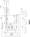
- the system 100 includes at least one telematics device 106 in data communication over a communication network 112 with a server 110.
- a telematics device 106 is provided for each vehicle 104 that is managed by the system 100.
- the server 110 receives data from the telematics device 106 and provide instructions to the telematics device 106 via communication network 112.
- the server 110 includes a storage unit, a processor, and a communication interface (not shown in Figure 1 ).
- the server stores, in the storage unit, a plurality of data definition sets.
- the data definition sets defines how vehicle signals are encoded.
- the data definition sets is used to configure the telematics device 106 for decoding vehicle signals.
- the plurality of data definition sets form a vehicle signal configuration management system (VSIG), which is generally too large to store locally on a telematics device 106.
- VSIG vehicle signal configuration management system
- the communication network 112 may be any network capable of carrying data, including the Internet, Ethernet, plain old telephone service (POTS) line, public switch telephone network (PSTN), integrated services digital network (ISDN), digital subscriber line (DSL), coaxial cable, fiber optics, satellite, mobile, wireless (e.g. Wi-Fi, WiMAX), SS7 signaling network, fixed line, local area network, wide area network, and others, including any combination of these, capable of interfacing with, and enabling communication between the telematics device 106 and the server 110.
- POTS plain old telephone service
- PSTN public switch telephone network
- ISDN integrated services digital network
- DSL digital subscriber line
- coaxial cable fiber optics
- satellite mobile
- wireless e.g. Wi-Fi, WiMAX
- SS7 signaling network fixed line, local area network, wide area network, and others, including any combination of these, capable of interfacing with, and enabling communication between the telematics device 106 and the server 110.
- the fleet 102 of vehicles 104 includes at least one electric vehicle.
- the term “electric vehicle” used herein broadly refers to any vehicle having an electric power train, that is, motive power provided by an electric motor and an energy storage component. It will be understood that the term “electric vehicle” used herein includes “hybrid vehicles” having both an electric power train and an internal combustion engine.
- the fleet 102 can also include non-electric vehicles.
- non-electric vehicles used herein broadly refers to vehicles whose only source of motive power is provided by an internal combustion engine.
- Non-electric vehicles include, but is not limited to, gasoline, propane, and diesel vehicles.
- the fleet 102 may include a plurality of electric vehicles 104 that replace non-electric vehicles.
- the fleet 102 is shown having three vehicles 104 for illustrative purposes, however, the fleet 102 is not limited to three vehicles 104. Any number of vehicles 104 can be included in the fleet 102.
- a system 100 manages a portion of the fleet 102 of vehicles.
- a system 100 may only manage electric vehicles of a fleet 102 and not manage non-electric vehicles of the fleet 102.
- an entire fleet 102 is managed by one system 100.
- the telematics device 106 includes a connection port 108 for connecting to the vehicle, a memory 118, a processor 120, a communications module 116 for communicating with a communications network, and a power supply circuit 126.
- the telematics device 106 is connected to the vehicle 104 via the connection port 108.
- the connection port 108 can be an OBD2 port.
- the connection port 108 provides access to OBD2 communication data and/or non-OBD2 communication data, that is, data that does not use the OBD2 communication protocol.
- Non-OBD2 communication protocols include, but are not limited to, broadcast serial run-time data or the unified diagnostics system (UDS) protocol.
- Non-OBD2 communication data includes electric vehicle specific data.
- the telematics device 106 can be a purpose built computer having the processor 120 and the memory 118 therein.
- the processor 120 can be any suitable processors, controllers, or digital signal processors that provides sufficient processing power, depending on the configuration, purposes, and requirements of the telematics device 106.
- the processor 120 can include more than one processor, with each processor configured to perform different dedicated tasks.
- the processor 120 is configured to obtain data from the vehicle 104 when the telematics device 106 is connected to the vehicle 104.
- the processor 120 can obtain data from a serial network on-board the vehicle via the connection port 108.
- the serial network on-board the vehicle 104 is a Controller Area Network (CAN) bus.
- the CAN bus is a standard vehicle bus that allows microcontrollers and devices on a vehicle to communicate with each other in applications without a host computer.
- the CAN bus protocol is a message-based protocol, designed originally for multiplex electrical wiring within automobiles, but may also be used in other contexts.
- the memory 118 is operably connected to the processor 120.
- the memory 118 is a non-transitory computer-readable storage medium.
- the memory 118 is configured to store instructions executable by the processor 120 to perform at least one of the methods described herein.
- the memory 118 can also store a plurality of fingerprints and a plurality of vehicle identification instruction sets. Each fingerprint is stored in association with a vehicle identification instruction set.
- a fingerprint includes a CAN bus identifier and a payload for a CAN bus message.
- a fingerprint can also include a payload filter for the CAN bus message.
- the processor 120 compares the data obtained from the vehicle 104 to the plurality of fingerprints stored in memory 118 to identify a fingerprint that matches the data obtained from the vehicle 104. The identification of a matching fingerprint is described in more detail below.
- the processor 120 determines a vehicle identification instruction set that corresponds to the fingerprint identified by the data obtained from the vehicle 104. That is, based on the captured data, the processor 120 determines a vehicle identification instruction set for the vehicle 104 from the plurality of vehicle identification instruction sets.
- the processor 120 executes instructions to carry out the vehicle identification instruction set in order to identify the vehicle 104.
- the vehicle identification instruction set includes one or more instructions to identify the vehicle 104.
- the vehicle 104 is identified by a vehicle identification number (VIN) and the vehicle instruction set includes an instruction to retrieve the VIN.
- VIN vehicle identification number
- the VIN is unique for each vehicle 104. That is, no two vehicles 104 can have the same VIN.
- the processor 120 determines a vehicle mode of the electric vehicle 104.
- the determination of a vehicle mode is described in more detail below.
- the vehicle mode can be any one or more of the following: a charging state, a driving state, an off state, and an idling state.
- the processor 120 determines if the vehicle 104 is charging or driving.
- the processor 120 can identify the "mode" along with the vehicle 104 such that charging events are tracked separately than driving events.
- the processor 120 can also identify if the vehicle 104 is: (i) plugged in but not charging, or (ii) plugged in and charging.
- the processor 120 includes a driving module 122 for determining if the electric vehicle 104 is driving.
- the processor 120 includes acharging module 124 for determining if the electric vehicle 104 is charging. Each of these modules are described in more detail below.
- the telematics device 106 includes a communications module 116 for communicating with the server 110 via the communication network 112.
- the telematics device 106 provides local vehicle data to the server 110.
- the telematics device 106 receives central vehicle data from the server 110.
- the local vehicle data includes data from a vehicle's serial network.
- the local vehicle data can also include a vehicle identifier of the vehicle 104.
- the local vehicle data is used to determine a mode of operation of the electric vehicle 104.
- the power supply circuit 126 provides power to circuit components of the telematics device 106 including the processor 120 and memory 118.
- the method 200 includes providing 202 a telematics device 106 for an electric vehicle 104, using 204 the telematics device 106 to identify the electric vehicle 202, providing a data definition set for the electric vehicle 104 to the telematics device 106, and determining 208 a mode for the electric vehicle 104.
- the method 200 begins with providing 202 a telematics device 106 for an electric vehicle 104 of the fleet 102.
- a telematics device 106 can be provided for more than one electric vehicle 104 of the fleet 102.
- the telematics device 106 can be installed in the electric vehicle 104 by connecting the connection port 108 to aconnector in the electric vehicle 104.
- the connector in the vehicle 104 is an OBD2 Data Link Connector
- the connection port 108 is an OBD2 connector.
- the data obtained from the electric vehicle 104 is stored in the telematics device 106.
- the electric vehicle 104 can be automatically identified at 204 using data obtained from the vehicle's serial network without user input.
- the data obtained from the vehicle's serial network is referred to as a "fingerprint" because it is used to identify the vehicle.
- the telematics device 106 A generate a list of candidate vehicle makes and models and use the fingerprint to identify the vehicle's make and model from the list of candidates.
- the fingerprint is used to select a vehicle identification instruction set that, when performed, identifies the vehicle.
- the identity of the vehicle 104 is represented by a vehicle identification number (VIN) and the vehicle identification instruction set retrieves the VIN from the electric vehicle 104.
- VIN vehicle identification number
- the instruction set to identify a vehicle can vary for each make, model, and/or year.
- the vehicle identifier is periodically broadcast on the serial network.
- the vehicle identification instruction set sets out various ways for listen for such broadcasts since they can vary with each make, model, and year of vehicle.
- the vehicle identification instruction set can also set out various way to request the vehicle identifier from vehicles that do not have broadcast the vehicle identifier.
- the selected vehicle identification instruction set is performed to identify the electric vehicle 104.
- the vehicle identification instruction set is performed to determine the VIN.
- the execution of the vehicle identification instruction set can be the first interaction that the telematics device 106 has with the vehicle 104.
- the execution of the vehicle identification instruction set can be the only interaction that the telematics device 106 has with the vehicle 104 prior to receiving a data definition set at 206, which allows the telematics device 106 to decode data obtained from the vehicle 104.
- Electric vehicle data is stored in different locations within the electric vehicle, depending on the vehicle make, model, and/or year.
- Obtaining a data definition set at 206 involves retrieving information about signals that are encoded for that vehicle.
- each data definition set is a specific to a particular vehicle, such as for a particular VIN.
- data definition sets are specific to a vehicle make, model, and year, or any combination of the vehicle make, model, and/or year.
- the data definition set is retrieved from the server 110, which stores a plurality of data definition sets, that is, the vehicle signal configuration management system (VSIG).
- the VSIG stores a data definition set for each potential vehicle.
- a VSIG that is remote from the telematics device 106 allows the VSIG to be dynamically updated when new vehicles or configurations are created or modified.
- the VSIG includes a data definition set for each vehicle make, model, and year.
- the telematics device 106 provides information identifying the vehicle that is sufficient for obtaining a data definition set. For example, when data definition sets are specific to the combination of vehicle make, model, and year, the telematics device 106 provides the vehicle make, model, and year. In contrast, in some embodiments, the telematics device 106 provides information identifying a specific vehicle, such as a VIN and the server 110 determines the vehicle make, model, and year, based on the VIN provided, in order to select the appropriate data definition set.
- a specific vehicle such as a VIN
- the server 110 determines the vehicle make, model, and year, based on the VIN provided, in order to select the appropriate data definition set.
- the telematics device 106 uses the data definition set to decode data obtained from the serial network on-board the vehicle 104.
- the decoded data are used to determine a mode of the electric vehicle 104.
- the decoded data are used to determine if the electric vehicle 104 is charging or driving.
- information about whether the electric vehicle 104 is charging or driving vehicle is used to track operating performance.
- the method 204 identifies the electric vehicle 104.
- the method 204 occurs within the in-vehicle hardware such as the telematics device 106, without the need for a third party or a server connection.
- the telematics device 106 stores a plurality of fingerprints and associated vehicle identification information sets in the onboard memory 118.
- Fingerprints may include a set of CAN message identifiers, a payload of a specific message identifiers, a combination of payloads across multiple message identifiers (i.e., VIN), and/or a cyclic rate of transmission for each defined message identifier.
- Each electric vehicle 104 has a unique fingerprint. For example, a vehicle 104 may have approximately 100 unique CAN message identifiers present on its CAN network, that is, a serial network onboard the vehicle, at any given time. A subset of these messages and message payloads are identified as sufficient to identify this vehicle uniquely compared to all other vehicles.
- data from the vehicle's serial network is obtained. That is, a vehicle's fingerprint is obtained.
- Data is obtained from the serial network for a predetermined period time.
- data on the vehicle's serial network is captured longer than required in order to ensure sufficient data is captured.
- the predetermined period of time can be up to 3 times longer than the time required to capture sufficient data to form fingerprint. That is, the predetermined period of time can be 3 times the maximum nominal broadcast rate defined in the fingerprint. In at least one embodiment, the predetermined period of time can be 5 seconds.
- the captured data is stored on the memory 118 of the telematics device 106.
- the captured data is compared to the plurality of fingerprints stored in the memory 118 of the telematics device 106.
- the plurality of fingerprints stored in the memory 118 includes CAN bus identifiers, message payloads, and payload filters.
- An example of a portion of a plurality of fingerprints stored on the telematics device 106, is provided in Table A. Table A is shown for illustrative purposes only. For example, other fingerprints may include additional CAN bus message information and/or may not include the message payload mask.
- Each fingerprint in the database has a predefined corresponding vehicle identification instruction set.
- the captured fingerprint is matched with one or more fingerprints to select a vehicle identification instruction set that corresponds to the captured data.
- the selected vehicle identification instruction set is performed.
- a valid vehicle identifier is determined.
- the vehicle identifier is a specific to the vehicle, such as a VIN.
- the vehicle identifier A be a combination of the vehicle make, model, and year.
- Vehicles can adopt different communication protocols, depending on the vehicle make, model, and/or year. Some communication protocols may be compliant with the OBD2 standard.
- Figure 4 illustrated therein is a conventional method 300 for using a telematics device to identify the vehicle 104 when the communication protocol supported by the vehicle 104 is OBD2 compliant.
- the telematics device can be woken up when power is applied and the telematics device is connected to the vehicle. Where the telematics device is not power cycled (e.g., unplugged from the electric vehicle 104 and then re-plugged in), the protocol last used by the telematics device is also used at 304.
- the telematics device detects the protocol at 306.
- a CAN bus baud rate is identified, and, at 308, for each baud rate, the telematics device listens for passive identification of the CAN bus.
- the vehicle 104 has a data gateway, the telematics device 106 actively identifies the CAN bus, at 310.
- legacy OBD2 protocols are detected, such as K-Line (ISO 9141, KWP), SAE J1850 - PWM, and SAE J1850 - VPW protocols.
- the VIN is identified, at 316 the VSIG signature definitions are returned and, at 318 logging and tasks are performed.
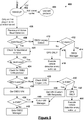
- FIG. 5 illustrated therein is a method 400 for using the telematics device 106 to identify the vehicle 104, in accordance with an embodiment. Similar to 302, at 402 the telematics device 106 can be woken up with the application of power and connection to the vehicle. For illustrative purposes only, Figure 5 shows 12 Volts (V) and a connection to a CAN bus. However, it will be understood that other embodiments can use different power levels and connect to different communication networks on-board a vehicle. Where the telematics device 106 is not power cycled (e.g., unplugged from the electric vehicle 104 and then re-plugged in), the protocol last used by the telematics device 106 can also be used at 404, similar to 304. Where the telematics device 106 is first attached to the vehicle 104, or where no protocol is saved by the telematics device 106, the telematics device 106 attempts to detect the communication protocol of the vehicle 104.
- V Volts
- the CAN bus baud rate is identified at 406.
- the CAN bus baud rate is first identified passively. Since there are a limited number of valid potential baud rates, each potential baud rate is checked in sequence to determine if it is the baud rate of the CAN bus.
- the telematics device 106 is configured to listen to pre-existing broadcast data on the CAN bus at a first potential baud rate and capture a portion of this data for a pre-determined interval.
- the pre-existing broadcast data can be broadcast from vehicle controllers. If data captured in the pre-determined interval is valid, then the telematics device 106 determines that the first potential baud rate is the baud rate of the CAN bus.
- the telematics device 106 determines that the first potential baud rate is not be the baud rate of the CAN bus and the telematics device 106 checks another potential baud rate.
- passive identification of the CAN bus baud rate requires pre-existing broadcast data on the CAN bus, which is not available for vehicles having a data gateway.
- the telematics device 106 can actively identify the CAN bus baud rate in vehicles 104 that have a data gateway. To actively identify the CAN bus baud rate, the telematics device 106 also tests each valid potential baud rate in sequence. However, with active identification, the telematics device 106 transmits a few test messages to the CAN bus at a first potential baud rate. If the test messages are acknowledged by the data gateway, the telematics device 106 determines that the CAN bus baud rate is the first potential baud rate. If the test messages are not acknowledge by the data gateway, the telematics device 106 determines that the CAN bus baud rate is not the first potential baud rate and proceeds to test another potential baud rate.
- the telematics device 106 determines, at 408 if there is a valid baud. If there is not a valid baud, the telematics device 106 detects, at 410, if the vehicle 104 supports any of the legacy OBD2 protocols, similar to 312. If the telematics device 106 determines that the vehicle 104 supports a legacy OBD2 protocol at 412, the OBD2 manager is triggered at 414.
- the OBD2 manager allows for the retrieval of data from OBD2 compliant vehicles. That is, the OBD2 manager provides a data definition set in accordance with the OBD2 standards. In addition, the OBD2 manager provides specifics for determining a mode of an OBD2 compliant vehicle, namely detection of the vehicle 104 being on or off.
- the vehicle 104 enters a GPS only mode at 416. In the GPS only mode, the vehicle communication protocol detection is executed at every wake up at 418.
- the telematics device 106 checks for blacklisted vehicles, at 420. Where the vehicle 104 is blacklisted, at 422, the telematics device 106 returns to the blacklist check, at 420.
- the blacklist identifies vehicles that require special procedures. For example, some vehicles sound an audible alarm when a device, such as the telematics device 106, attempts to communicate with the vehicle when the doors are locked. In this case, the telematics device 106 is configured to not communicate with the vehicle when the doors are locked in order to avoid sounding the audible alarm. Thus, the blacklist identifies exceptions so that the telematics device 106 can carry out special procedures when an exception is identified.
- the telematics device 106 checks whether the vehicle 104 supports the OBD2 CAN protocol, at 424. At 426, the telematics device 106 can determine if the OBD2 CAN protocol is supported.
- the telematics device 106 checks for electric vehicle fingerprints, at 428. That is, at 428, the telematics device 106 obtains data from a serial network on-board the electric vehicle 104 and compare the data obtained with the plurality of stored fingerprints.
- the telematics device 106 enters GPS only mode. Similar to 416 and 418, once in GPS only mode, the telematics device 106 executes the vehicle communication protocol detection at every wake up 444.
- the method 400 proceeds to identify the vehicle 104 at 343, which involves a vehicle identification instruction set. That is, a vehicle identification instruction set is obtained and executed at 343. Following identification of the vehicle 104, the telematics device 106 enters the electric vehicle manager, at 440.
- the OBD2 VIN is retrieved at 436, similar to 314.
- the telematics device 106 stores a list of VINs that correspond to an electric vehicle.
- the telematics device 106 determines if the VIN retrieved at 436 corresponds to an electric vehicle by matching the retrieved VIN to the stored list of VINs. Where the VIN corresponds to an electric vehicle, the telematics device 106 enters the electric vehicle manager, at 440. Where the VIN does not correspond to an electric vehicle, the telematics device 106 enters the OBD2 manager, at 442.
- the data definition set obtained from the VSIG provides the telematics device 106 with information to collect data from the vehicle 104 and transition through the various modes. There are a number of signal attributes that the telematics device 106 uses to accurately parse and calculate local electric vehicle data. The telematics device 106 identifies when signals are valid. The telematics device 106 identifies in what modes the telematics device 106 transmits local vehicle data to the server 110 and at what rates.
- the data definition set may include metadata about each signal definition, including: signal validity criteria, maximum value allowed, minimum value allowed, and default value after signal hits timeout. As well as signal timeout values, time after signal reverts to default value, signal value type, and physical protocol specifications.
- the VSIG database architecture may be compatible with OBD2, J1939, J1587, UDS, KWP, Transport Protocol, ISO 15765-2, BMW-TP, and other protocols.
- the data definition set may include saturation limits for signal scaling (i.e. useable versus actual battery state of charge (SOC)), maximum saturation limit, minimum saturation limit, and mode transmit limits for signals (i.e. for UDS type request signals).
- saturation limits for signal scaling i.e. useable versus actual battery state of charge (SOC)
- maximum saturation limit i.e. useable versus actual battery state of charge (SOC)
- minimum saturation limit i.e. for UDS type request signals.
- the data definition set may include specifications for each signal such as maximum and minimum transmit limits for each signal request for each vehicle mode (e.g. Scanning, Driving, Charging).
- specifications for each signal such as maximum and minimum transmit limits for each signal request for each vehicle mode (e.g. Scanning, Driving, Charging).
- the data definition set may include global vehicle parameters.
- the global vehicle parameters may include global minimum or maximum transmit rates.
- the telematics device 106 can also include an user interface to receive input defining the local vehicle data obtained or collected from vehicle by the telematics device 106 in real-time, the collection rate of the local vehicle data, the local vehicle data to be transmitted from the telematics device 106 to the server 110 in real-time, as well as the transmission rates of the local vehicle data.
- the telematics device 106 is configured to collect and transmit the following local vehicle data to the server 110: vehicle speed and odometer.
- vehicle speed and odometer The telematics device 106 can be configured to also include a logging rate and a signal delta in the transmission of each of a vehicle speed and odometer.
- the telematics device 106 can define real-time update rates by mode. In some embodiments, the telematics device 106 may minimize data usage. For example, in some embodiments, the telematics device 106 may transmit signals only when the signal changes. In other embodiments, the telematics device 106 may transmit signals at a pre-defined transmission rate.
- Updates to VSIG Configuration may be completed as in Table B. TABLE B Real-time Update Rates Signal Name Moving Mode Idling Mode Charging Mode GPS Distance: 100m Rate: 60s Rate: 300s Vehicle Speed Rate: 1s HV Battery State of Charge Rate: 10s Rate: 30s Rate: 60s Charger Power Rate: 30s Battery Temperature Engine Hours End of Trip Seatbelt Status Signal Delta: 1 OBD2 DTCs Signal Delta: 1
- the telematics device 106 is configured to include any one or more of data relating to real-time update, rates, allowing the system to configure the rate of raw data in any vehicle mode, and as a function of the time elapsed or the distance the vehicle 104 has travelled, or upon specific vehicle events.
- the data definition set is obtained using the vehicle identification obtained from 204.
- the electric vehicle data includes any one or more of battery state of charge, vehicle plug in status, vehicle current charging status, battery power, electrical current of the battery, electrical voltage of the battery, vehicle speed, vehicle fuel rate, and odometer value.
- the electric vehicle information may be available at the physical OBD2 port. However, the digital location of the electric vehicle information may be different for each make, model, and year of vehicle.
- the communications module 116 transmits the VIN, at 230, to the server 110 via the network 112 (e.g., the Internet).
- the network 112 e.g., the Internet
- the server 110 includes the vehicle signals database (VSIG) and, at 232, the data definition set is retrieved from the VSIG database. At 234, the retrieved data definition set is transmitted from the server 110 to the telematics device 106.
- VSIG vehicle signals database
- the data definition set can include any one or more of: CAN bus signal definitions, including CAN identifiers, start and end bits, and scaling and offset factors, and request and response definitions that detail which parameters to request from the vehicle, and information on how to interpret the vehicle's response.
- the telematics device 106 is able to communicate at 326, via the OBD2 port 108, with the electric vehicle 104.
- the telematics device 106 uses the data definition set to communicate with the electric vehicle 104.
- the telematics device 106 calculates trip and charge metrics for the electric vehicle 104.
- the telematics device 106 calculates various metrics. At the conclusion of the trip, the telematics device 106 uploads the overall metrics for the event.
- the trip metrics may include any one or more of Trip Start time, Trip Duration, Total Idle Time, Total Distance, Starting Odometer, Ending Odometer, Outside Temperature, Total Fuel Consumed, Idle, Fuel Consumed, Starting Battery State of Charge, Ending Battery State of Charge, Distance driven on Electricity, Number of Idling events, Number of hard braking events, Number of hard acceleration events, Average Speed, and Maximum Speed.
- Charge metrics summarize the details of the charging event and the telematics device 106 uploads the charge metrics to the server at the end of the event.
- Charge metrics may include any one or more of Charge Start time, Charge Duration, Maximum Charging Power (Watts), Total Charging Energy, Estimated Charging Losses, Starting Battery State of Charge, Ending Battery State of Charge, GPS Latitude, GPS Longitude, GPS Altitude, and Charge Energy Interval Data.
- the telematics device 106 calculates the total energy entering the vehicle 104 via the charge plug during a periodic (e.g., 15 minute) window to determine the charge energy interval data.
- a periodic (e.g., 15 minute) window to determine the charge energy interval data.
- a common reporting mechanism for electric utility data is "15 minute interval data”.
- the telematics device 106 calculates the trip and charge metrics with a relevant calculator, such as a driving calculator or a charging calculator.
- a relevant calculator such as a driving calculator or a charging calculator.
- the determination of state is used to select which calculator to activate.
- the telematics device 106 may also upload live "raw" data from the vehicle 104 where the instantaneous GPS position or State of Charge of the vehicle, or speed, etc., is desired.
- the telematics device 106 includes data rate profiles for live data upload. Data rate profiles change the rate of data upload to be slower during charge than for driving. This allows savings on wireless data transfer costs, since the total on hours during charge are much higher than during driving. Electric vehicles tend to spend more time charging than driving, for example 12 hours charging/day and 2 hours driving/day.
- the telematics device 106 receives high data rates during driving in order to monitor the location of the vehicles when driving. During a charge, not much of interest is happening as the state of charge goes up slowly.
- the telematics device 106 uploads a single charge metrics package.
- the charge metrics package may have a fixed size.
- the vehicle mode detection method 206 illustrated therein is the vehicle mode detection method 206, in accordance with an embodiment.
- the telematics device 106 may determine operating modes for the electric vehicle.
- the telematics device 106 uses the vehicle diagnostic data to determine in which mode the vehicle 104 operates (for example, driving, charging, off, or plugged in).
- the telematics device 106 determines if and/or when the electric vehicle 104 is charging to determine an electric vehicle charging mode.
- the determination of the charging mode may be performed using the method 700 of Figure 10 .
- the telematics device 106 determines if and/or when the electric vehicle 104 is driving to determine an electric vehicle driving mode.
- the determination of the driving mode may be performed using the method 800 of Figure 11 .
- the telematics device 106 determines if the electric vehicle 104 is plugged in to a charging source.
- the charging source may be, for example, an electric supply grid.
- the telematics device 106 determines if the electric vehicle 104 is on or off. Where power is being supplied from the power system of the electric vehicle 104 to the driving system of the electric vehicle 104, the electric vehicle 104 is on. Where power is not being supplied from the power system to the driving system, the electric vehicle is off.
- the telematics device 106 may not directly make an on/off determination. For example, if the vehicle 104 wakes in the middle of the night to call the manufacturer with diagnostics, it is not on. In this case, the telematics device 106 wakes up upon detecting runtime CAN bus traffic, but since the telematics device 106 does not detect that the vehicle 104 is charging or driving, the telematics device 106 waits in the scan mode for either the CAN bus to go silent (upon the telematics device 106 will go to sleep), or the vehicle 104 to start driving or charging.
- the telematics device 106 determines the odometer reading of the electric vehicle 104. Once the data definition set is obtained from VSIG, then the odometer is read periodically during driving and attached to end of trip metrics.
- a vehicle mode determination method 500 illustrated therein is a vehicle mode determination method 500, in accordance with an embodiment.
- the first vehicle determination has occurred and data definitions set has been retrieved from the server.
- the telematics device 106 obtains a vehicle speed, a battery power, an engine speed (rpm). Optionally, the telematics device 106 obtains a charger power, a signal indicating that the vehicle 104 is driving (herein referred to as a "driving signal") and a signal indicating that the vehicle 104 is charging (herein referred to as a "charging signal"). If a driving signal is not available from the vehicle 104, the driving module 122 operates in accordance with Figure 10 to determine if the vehicle 104 is driving. If a charging signal is not available from the vehicle 104, the charging module 124 operates in accordance with Figure 11 to determine if the vehicle 104 is charging.
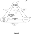
- the high level state determination is separated into a scan mode 502, a driving mode 504, and a charging mode 506.
- the scan mode 502 is where the state of the vehicle 104 is not yet determined, or it is a nuisance wakeup, or some other event.
- the driving mode 504 is where the vehicle 104 is considered to be in a drive ready state. The vehicle 104 could be idling, moving, parked. For example, if a user is sitting in the car, the user would expect the drive ready light to be lit on the vehicle's dashboard.
- the charging mode 506 is where the vehicle 104 is currently plugged in and charging the battery.
- the method 600 includes, at 602, providing a telematics device 106 on each electric vehicle. Providing a telematics device 106 involves connecting the telematics device 106 to the vehicle 104 via an OBD2 port.
- the method 600 includes, at 604, identifying the process (e.g., as described with reference to Figures 3 through 6 ) needed to retrieve the vehicle identification number (VIN).
- the method 600 includes, at 606, identifying the electric vehicle with the telematics device 106 using the VIN.
- the method 600 includes, at 608, using the VIN to retrieve vehicle diagnostic data from a remote server.
- the method 600 includes, at 610, using the vehicle diagnostic data to determine which mode the vehicle 104 operates (driving, charging, off, or plugged in).
- the method 600 includes, at 612 modifying collection parameters.
- the behavior of collection is modified in a variety of ways. For example, which signals are collected, how the telematics device 106 interacts with the vehicle, and the rate that data is requested from the vehicle.
- the telematics device 106 may modify rates of data capture. For instance, change is slow during charging so the rate of data capture is lower. However, change is rapid during driving so the rate of data capture is higher.
- the method 600 further includes retrieving a data definition set from the VSIG, communicating the data definition set to the vehicle 104, and calculating trip and charge metrics.
- the method 600 can further include determining the power of an on-board or off-board battery charger.
- the method 600 can further include determining the vehicle speed, battery power and engine speed.
- the method 600 can further include determining if the electric vehicle is charging. Determining this mode (driving/off/idling/charging) of the vehicle 104 is used to enforce minimum and/or maximum signal transmit rates to avoid unwanted vehicle behavior. For example, if the telematics device 106 communicates with the vehicle 104 while the vehicle 104 is "off", then the telematics device 106 may trigger the car alarm.
- the telematics device 106 may keep the vehicle computer system awake and drain the 12V battery in a few hours. In these cases, the telematics device 106 controls the way and rate at which the telematics device 106 communicates with the vehicle 104 based on the vehicle mode.
- FIG 10 illustrates a method 700 for determining if the electric vehicle is charging.
- the method 700 is executed by the charging module 124.
- the vehicle 104 is inferred to be such a state using the local electric vehicle data retrieved by the telematics device 106.
- Charging mode data may include any one or more of charging summary calculators, charge parameters, real-time data, raw data (guaranteed), and rates and signals defined by the data definition set.
- the telematics device 106 checks for explicit signals indicating that the vehicle 104 is charging. For example, some vehicle provides an "isCharging” or “isChargingDC" signal. If, at 704 a charging signal is available (i.e. defined in data definition set), and if, at 706 the charging signal is true, then the telematics device 106 determines that the electric vehicle is charging, at 708, and if not, the telematics device 106 determines that the electric vehicle is not charging, at 710.
- the telematics device 106 determines from AC charger input signals, if charger power signal is available, at 712.
- the AC charger signals may include AC voltage, current, or AC charger power. If, at 714, the charger power is greater than zero, then the telematics device 106 determines that the electric vehicle is charging, at 716. If, at 714, charger power is zero, then the telematics device 106 determines that the electric vehicle not charging, at 718.
- the telematics device 106 determines, at 720, if the vehicle 104 is stopped. Where the vehicle speed is not zero, the vehicle 104 is determined to be not charging, at 722. Where the vehicle 104 is stopped at 720, and the engine is off, at 724, the electric vehicle is determined to be charging, at 726. Where battery power is greater than 100%, at 728, and the engine speed (rpm) is zero, or does not exist, the telematics device 106 determines that the electric vehicle is charging at 730, otherwise the telematics device 106 determines that the electric vehicle is not charging.
- FIG 11 illustrates a method 800 for determining if an electric vehicle is driving, in accordance with an embodiment.
- the method 800 is executed by the driving module 122.
- the telematics device 106 checks for a driving signal.
- Driving mode data may include any one or more of trip summary calculators, trip parameters, park event summary, real-time data, raw data (guaranteed), and rates and signals defined by the data definition set, trip data, distance, and fuel consumed.
- a driving signal is available signal (i.e. defined in data definition set)
- the telematics device 106 determines that the electric vehicle is driving, at 808, otherwise the telematics device 106 determines that the electric vehicle is not driving at 810.
- the telematics device 106 determines if the vehicle is moving, at 812. If the vehicle speed is greater than zero, the telematics device 106 determines that the electric vehicle is driving.
- the telematics device 106 determines if the engine is on, at 816. If the engine speed is greater than zero, the telematics device 106 determines that the electric vehicle is driving, at 818. Where the engine rpm is zero, at 816, the telematics device 106 determines, at 820, if the battery is discharging battery power less than -100W (i.e., discharging great than 100W). If so, then the telematics device 106 determines that the electric vehicle is driving at 822, otherwise the telematics device 106 determines that the electric vehicle is not driving, at 824.
- the driving signal if it is available it overrules other conflicting triggers.
- Figure 12 illustrates a method 900 for determining 904 if an electric vehicle in a driving mode 902 is on a trip 906 or is parked 908, in accordance with an embodiment.
- the telematics device 106 looks for a signal indicating that the vehicle is parked (herein referred to as a "park signal") from the data definition set. Should a park signal be available, a trip will not begin until the vehicle has been shifted away from park. Instead a park event summary will be generated.
- the telematics device 106 determines, at 904, if there is a park signal. If there is a park signal, then the telematics device 106 determines that the vehicle is parked at 908. If the vehicle speed is zero for a period of time (e.g., 5 minutes), the telematics device 106 determines that the vehicle is idling at 912. If the vehicle speed is above zero, the telematics device 106 determines that the vehicle is moving, at 910.
- a period of time e.g., 5 minutes
Landscapes
- Engineering & Computer Science (AREA)
- Computer Networks & Wireless Communication (AREA)
- Signal Processing (AREA)
- Power Engineering (AREA)
- Transportation (AREA)
- Mechanical Engineering (AREA)
- Health & Medical Sciences (AREA)
- Computing Systems (AREA)
- General Health & Medical Sciences (AREA)
- Medical Informatics (AREA)
- Electric Propulsion And Braking For Vehicles (AREA)
Description
- The embodiments disclosed herein relate to electric vehicles, and, in particular to systems and methods for managing a fleet of electric vehicles.
- On-board diagnostics (OBD) is an automotive term referring to a vehicle's self-diagnostic and reporting capability. OBD systems give a vehicle owner or a repair technician access to the status of the various vehicle subsystems. Early versions of OBD (OBD1) would simply illuminate a malfunction indicator light if a problem was detected but would not provide any information as to the nature of the problem. Modern OBD implementations use a standardized digital communications port to provide real-time data in addition to a standardized series of diagnostic trouble codes (DTCs) which allow a user to rapidly identify and remedy malfunctions within the vehicle.
- On-Board Diagnostics 2 (OBD2) is an improvement over OBD1 and the OBD2 standard specifies the type of diagnostic connector (e.g., an OBD2 Data Link Connector) and its pinout, the electrical signaling or communication protocols available, and the messaging format. The OBD2 standard also provides a candidate list of vehicle parameters to monitor along with how to encode the data for each.
- The vehicle side of the OBD2 connector includes a pin in the connector that provides power for the scan tool from the vehicle battery, which eliminates the need to connect a scan tool to a power source separately.
- The OBD2 standard provides a list of standardized Diagnostic Trouble Codes (DTCs). As a result of this standardization, a single device can query the on-board computer(s) for these parameters in any vehicle. OBD2 standardization was prompted to simplify diagnosis of increasingly complicated emissions equipment. Although only emission-related codes and data are required to be transmitted according to U.S. legislation, most manufacturers have made the OBD2 Data Link Connector the main connector in the vehicle through which all systems are diagnosed and reprogrammed.
- OBD2 DTCs are 4-digits and preceded by a letter: P for engine and transmission (powertrain), B for body, C for chassis, and U for network. Manufacturers may also add custom data parameters to their specific OBD2 implementation, including real-time data requests as well as additional diagnostic trouble codes.
- As the OBD2 standard is based in emission standards, electric vehicles may be particularly challenging for the OBD2 communication protocol to support. Further, the OBD2 standard is not legally mandated for electric vehicles. In most cases, electric vehicles do not support the OBD2 communication protocol.
- Further, the OBD2 communication protocol, even where the OBD2 communication protocol is supported, may not contain electric vehicle data and information, such as battery state of charge (SOC) and energy consumption. Electric vehicle charging is a new vehicle state, where for gasoline, diesel, and propane vehicles (herein referred to as non-electric vehicles) there is only a driving state and an off state. Non-electric vehicles typically are "on" while the engine is on. Tracking the vehicle "mode" of a non-electric vehicle can be trivial as the vehicle is either on if the engine revolutions per minute (RPM) is greater than zero (e.g., Engine RPM > 0) or the vehicle is off.
-
United States patent application US 2015/224891 A1 discloses systems and methods for collecting data from electric vehicles, and for performing various different actions based on the collected data. A device, such as a remote device that communicates with a server, connects with a controller area network (CAN) of an electric vehicle, and collects data from the CAN and/or other types of data associated with the electric vehicle, e.g. geographical information that identifies a location of an electric vehicle, movement information that identifies whether the electric vehicle is in motion or not. -
United States patent application US 2007/083303 A1 discloses a system and method for providing vehicle information to a vehicle-diagnostic system (VDS). The VDS uses the vehicle information provided by the system to process vehicle diagnostic data associated with an operation of a vehicle. - The system includes a network server being adapted to (i) receive from a vehicle-diagnostic system a first request for particular vehicle information, (ii) provide to an information-retrieval engine the first request, (iii) receive from the information-retrieval engine an indication as to whether the particular vehicle information has been located, (iv) receive from the information-retrieval engine the particular vehicle information, and (v) provide to the vehicle-diagnostic system the particular vehicle information.
-
United States patent application US 2016/093216 A1 discloses programmable telematics systems and methods for two-way transmission of data and information between fleet vehicles and a fleet management system. The systems and methods employ a programmable telematics communications unit (TCU) configured to connect to the OBD II port of a vehicle, enabling two-way transmission of data and information between a fleet management system and vehicles in the fleet. The TCU device includes cellular data connectivity enabling communication with the management system through existing cellular telephone networks. The programmable TCU is toggled between multiple operating modes, wherein the TCU provides different functionality, such that a single vehicle participates in multiple vehicle programs (including separate vehicle rental and vehicle sharing programs) at different points in time. -
United States patent application US 2004/112124 A1 discloses a method for carrying out a remote diagnosis in a motor vehicle. The method comprises the steps of initializing the remote diagnosis, determining diagnostic data in the vehicle as a function of diagnostic mechanisms available in the vehicle at the time of the diagnostic data determination, and transferring at least portions of the diagnostic data to an external service centre which is designed to evaluate the transmitted diagnostic data. -
Chinese patent application CN 104 589 933 A discloses a tire pressure monitoring method for multiple vehicle models. The tire pressure monitoring method comprises the steps of obtaining relevant information of a vehicle from a CAN bus of the current vehicle, identifying a vehicle model to which the current vehicle belongs on the basis of the obtained relevant information of the vehicle, and obtaining driving data of the vehicle from the CAN bus of the current vehicle. The method further comprises the steps of reading a safety standard value corresponding to the vehicle model of the current vehicle, comparing the driving data of the vehicle with the safety standard value corresponding to the vehicle model of the vehicle, and if the driving data of the vehicle exceeds the safety standard value corresponding to the vehicle model of the vehicle, sending out an alarm signal. - Accordingly, there is a need for an improved system and method for managing a fleet of vehicles including electric vehicles.
- The present invention relates to a method and apparatus for managing an electrical vehicle of a fleet of vehicles as defined by independent claims 1 and 11. Other advantageous aspects of the present invention are defined by the appended dependent claims.
- Other aspects and features will become apparent, to those ordinarily skilled in the art, upon review of the following description of some exemplary embodiments.
- The drawings included herewith are for illustrating various examples of articles, methods, and apparatuses of the present specification. In the drawings:
-
Figure 1 is a block diagram of a system for managing a fleet of electric vehicles, in accordance with an embodiment; -
Figure 2 is a flow chart of a method for managing a fleet of electric vehicles, in accordance with an embodiment; -
Figures 3 to 5 are a flow charts of a method for fingerprinting an electric vehicle, in accordance with an embodiment; -
Figure 6 is a flow chart of a method for remote configuration management of an electric vehicle, in accordance with an embodiment; -
Figures 7 and8 are flow charts of a method for vehicle mode detection for an electric vehicle, in accordance with an embodiment; -
Figure 9 is a flow chart of a method for managing a fleet of electric vehicles, in accordance with an embodiment; -
Figure 10 is a flow chart of a method for determining if an electric vehicle is charging, in accordance with an embodiment; -
Figure 11 is a flow chart of a method for determining if an electric vehicle is driving, in accordance with an embodiment; and -
Figure 12 is a flow chart of a method for determining trip and parking status for an electric vehicle, in accordance with an embodiment. - It will be appreciated that numerous specific details are set forth in order to provide a thorough understanding of the exemplary embodiments described herein. However, it will be understood by those of ordinary skill in the art that the embodiments described herein may be practiced without these specific details. In other instances, well-known methods, procedures and components have not been described in detail so as not to obscure the embodiments described herein. Furthermore, this description is not to be considered as limiting the scope of the embodiments described herein in any way, but rather as merely describing the implementation of the various embodiments described herein.
- One or more systems described herein may be implemented in computer programs executing on programmable computers, each comprising at least one processor, a data storage system (including volatile and non-volatile memory and/or storage elements), at least one input device, and at least one output device. For example, and without limitation, the programmable computer may be a programmable logic unit, a mainframe computer, server, and personal computer, cloud based program or system, laptop, personal data assistance, cellular telephone, smartphone, or tablet device.
- Each program is preferably implemented in a high level procedural or object oriented programming and/or scripting language to communicate with a computer system. However, the programs can be implemented in assembly or machine language, if desired. In any case, the language may be a compiled or interpreted language. Each such computer program is preferably stored on a storage media or a device readable by a general or special purpose programmable computer for configuring and operating the computer when the storage media or device is read by the computer to perform the procedures described herein.
- One or more systems described herein may be implemented in computer programs executing on programmable computers, each comprising at least one processor, a data storage system (including volatile and non-volatile memory and/or storage elements), at least one input device, and at least one output device. For example, and without limitation, the programmable computer may be a programmable logic unit, a mainframe computer, server, and personal computer, cloud based program or system, laptop, personal data assistance, cellular telephone, smartphone, or tablet device.
- Each program is preferably implemented in a high level procedural or object oriented programming and/or scripting language to communicate with a computer system. However, the programs can be implemented in assembly or machine language, if desired. In any case, the language may be a compiled or interpreted language. Each such computer program is preferably stored on a storage media or a device readable by a general or special purpose programmable computer for configuring and operating the computer when the storage media or device is read by the computer to perform the procedures described herein.
- A description of an embodiment with several components in communication with each other does not imply that all such components are required. On the contrary a variety of optional components are described to illustrate the wide variety of possible embodiments of the present invention.
- Referring to
Figure 1 , illustrated therein is asystem 100 for managing a fleet 102 ofvehicles 104, in accordance with an embodiment. Thesystem 100 includes at least onetelematics device 106 in data communication over acommunication network 112 with aserver 110. Atelematics device 106 is provided for eachvehicle 104 that is managed by thesystem 100. - The
server 110 receives data from thetelematics device 106 and provide instructions to thetelematics device 106 viacommunication network 112. Theserver 110 includes a storage unit, a processor, and a communication interface (not shown inFigure 1 ). The server stores, in the storage unit, a plurality of data definition sets. The data definition sets defines how vehicle signals are encoded. The data definition sets is used to configure thetelematics device 106 for decoding vehicle signals. The plurality of data definition sets form a vehicle signal configuration management system (VSIG), which is generally too large to store locally on atelematics device 106. - The
communication network 112 may be any network capable of carrying data, including the Internet, Ethernet, plain old telephone service (POTS) line, public switch telephone network (PSTN), integrated services digital network (ISDN), digital subscriber line (DSL), coaxial cable, fiber optics, satellite, mobile, wireless (e.g. Wi-Fi, WiMAX), SS7 signaling network, fixed line, local area network, wide area network, and others, including any combination of these, capable of interfacing with, and enabling communication between thetelematics device 106 and theserver 110. - The fleet 102 of
vehicles 104 includes at least one electric vehicle. The term "electric vehicle" used herein broadly refers to any vehicle having an electric power train, that is, motive power provided by an electric motor and an energy storage component. It will be understood that the term "electric vehicle" used herein includes "hybrid vehicles" having both an electric power train and an internal combustion engine. - The fleet 102 can also include non-electric vehicles. The term "non-electric vehicles" used herein broadly refers to vehicles whose only source of motive power is provided by an internal combustion engine. Non-electric vehicles include, but is not limited to, gasoline, propane, and diesel vehicles. The fleet 102 may include a plurality of
electric vehicles 104 that replace non-electric vehicles. - The fleet 102 is shown having three
vehicles 104 for illustrative purposes, however, the fleet 102 is not limited to threevehicles 104. Any number ofvehicles 104 can be included in the fleet 102. - Furthermore, only one
vehicle 104 of fleet 102 is shown having atelematics device 106 for illustrative purposes, however, more than onevehicle 104 of a fleet 102 can have atelematics device 106. That is, asystem 100 manages a portion of the fleet 102 of vehicles. For example, asystem 100 may only manage electric vehicles of a fleet 102 and not manage non-electric vehicles of the fleet 102. In at least one embodiment, an entire fleet 102 is managed by onesystem 100. - The
telematics device 106 includes aconnection port 108 for connecting to the vehicle, amemory 118, aprocessor 120, acommunications module 116 for communicating with a communications network, and apower supply circuit 126. - The
telematics device 106 is connected to thevehicle 104 via theconnection port 108. Theconnection port 108 can be an OBD2 port. Theconnection port 108 provides access to OBD2 communication data and/or non-OBD2 communication data, that is, data that does not use the OBD2 communication protocol. Non-OBD2 communication protocols include, but are not limited to, broadcast serial run-time data or the unified diagnostics system (UDS) protocol. Non-OBD2 communication data includes electric vehicle specific data. - In at least one embodiment, the
telematics device 106 can be a purpose built computer having theprocessor 120 and thememory 118 therein. Theprocessor 120 can be any suitable processors, controllers, or digital signal processors that provides sufficient processing power, depending on the configuration, purposes, and requirements of thetelematics device 106. In at least one embodiment, theprocessor 120 can include more than one processor, with each processor configured to perform different dedicated tasks. - The
processor 120 is configured to obtain data from thevehicle 104 when thetelematics device 106 is connected to thevehicle 104. In some embodiments, theprocessor 120 can obtain data from a serial network on-board the vehicle via theconnection port 108. The serial network on-board thevehicle 104 is a Controller Area Network (CAN) bus. The CAN bus is a standard vehicle bus that allows microcontrollers and devices on a vehicle to communicate with each other in applications without a host computer. The CAN bus protocol is a message-based protocol, designed originally for multiplex electrical wiring within automobiles, but may also be used in other contexts. - The
memory 118 is operably connected to theprocessor 120. Thememory 118 is a non-transitory computer-readable storage medium. Thememory 118 is configured to store instructions executable by theprocessor 120 to perform at least one of the methods described herein. Thememory 118 can also store a plurality of fingerprints and a plurality of vehicle identification instruction sets. Each fingerprint is stored in association with a vehicle identification instruction set. A fingerprint includes a CAN bus identifier and a payload for a CAN bus message. A fingerprint can also include a payload filter for the CAN bus message. - The
processor 120 compares the data obtained from thevehicle 104 to the plurality of fingerprints stored inmemory 118 to identify a fingerprint that matches the data obtained from thevehicle 104. The identification of a matching fingerprint is described in more detail below. Theprocessor 120 determines a vehicle identification instruction set that corresponds to the fingerprint identified by the data obtained from thevehicle 104. That is, based on the captured data, theprocessor 120 determines a vehicle identification instruction set for thevehicle 104 from the plurality of vehicle identification instruction sets. - The
processor 120 executes instructions to carry out the vehicle identification instruction set in order to identify thevehicle 104. The vehicle identification instruction set includes one or more instructions to identify thevehicle 104. In at least one embodiment, thevehicle 104 is identified by a vehicle identification number (VIN) and the vehicle instruction set includes an instruction to retrieve the VIN. The VIN is unique for eachvehicle 104. That is, no twovehicles 104 can have the same VIN. - The
processor 120 determines a vehicle mode of theelectric vehicle 104. The determination of a vehicle mode is described in more detail below. The vehicle mode can be any one or more of the following: a charging state, a driving state, an off state, and an idling state. Aselectric vehicles 104 also include a charge mode, theprocessor 120 determines if thevehicle 104 is charging or driving. Theprocessor 120 can identify the "mode" along with thevehicle 104 such that charging events are tracked separately than driving events. Theprocessor 120 can also identify if thevehicle 104 is: (i) plugged in but not charging, or (ii) plugged in and charging. - The
processor 120 includes adriving module 122 for determining if theelectric vehicle 104 is driving. Theprocessor 120 includesacharging module 124 for determining if theelectric vehicle 104 is charging. Each of these modules are described in more detail below. - The
telematics device 106 includes acommunications module 116 for communicating with theserver 110 via thecommunication network 112. Thetelematics device 106 provides local vehicle data to theserver 110. Thetelematics device 106 receives central vehicle data from theserver 110. The local vehicle data includes data from a vehicle's serial network. The local vehicle data can also include a vehicle identifier of thevehicle 104. The local vehicle data is used to determine a mode of operation of theelectric vehicle 104. - The
server 110 communicates via awireless network 112 with thecommunications module 116 of thetelematics device 106. Theserver 110 receives local vehicle data from thetelematics device 106. Theserver 110 provides central vehicle data to thetelematics device 106. The central vehicle data includes vehicle signal encoding definition data (VSIG) for thetelematics device 106 to use for decoding data from a vehicle's serial network. The central vehicle data can also include vehicle diagnostic data for thetelematics device 106 to use for determining a mode of theelectric vehicle 104. - The
power supply circuit 126 provides power to circuit components of thetelematics device 106 including theprocessor 120 andmemory 118. - Turning now to
Figure 2 , illustrated therein is amethod 200 for managing a fleet 102 ofelectric vehicles 104, in accordance with an embodiment. Themethod 200 includes providing 202 atelematics device 106 for anelectric vehicle 104, using 204 thetelematics device 106 to identify theelectric vehicle 202, providing a data definition set for theelectric vehicle 104 to thetelematics device 106, and determining 208 a mode for theelectric vehicle 104. - The
method 200 begins with providing 202 atelematics device 106 for anelectric vehicle 104 of the fleet 102. Atelematics device 106 can be provided for more than oneelectric vehicle 104 of the fleet 102. Thetelematics device 106 can be installed in theelectric vehicle 104 by connecting theconnection port 108 to aconnector in theelectric vehicle 104. When the connector in thevehicle 104 is an OBD2 Data Link Connector, theconnection port 108 is an OBD2 connector. In at least one embodiment, the data obtained from theelectric vehicle 104 is stored in thetelematics device 106. - As the OBD2 communication protocol may not be supported by electric vehicles, standard OBD2 VIN retrieval methods may also not be supported. Instead, the
electric vehicle 104 can be automatically identified at 204 using data obtained from the vehicle's serial network without user input. The data obtained from the vehicle's serial network is referred to as a "fingerprint" because it is used to identify the vehicle. - In some embodiments, the telematics device 106 A generate a list of candidate vehicle makes and models and use the fingerprint to identify the vehicle's make and model from the list of candidates. In some embodiments, the fingerprint is used to select a vehicle identification instruction set that, when performed, identifies the vehicle. In some embodiments, the identity of the
vehicle 104 is represented by a vehicle identification number (VIN) and the vehicle identification instruction set retrieves the VIN from theelectric vehicle 104. The instruction set to identify a vehicle can vary for each make, model, and/or year. - In some vehicles, the vehicle identifier is periodically broadcast on the serial network. The vehicle identification instruction set sets out various ways for listen for such broadcasts since they can vary with each make, model, and year of vehicle. The vehicle identification instruction set can also set out various way to request the vehicle identifier from vehicles that do not have broadcast the vehicle identifier.
- Finally, the selected vehicle identification instruction set is performed to identify the
electric vehicle 104. In some embodiments, the vehicle identification instruction set is performed to determine the VIN. The execution of the vehicle identification instruction set can be the first interaction that thetelematics device 106 has with thevehicle 104. Furthermore, the execution of the vehicle identification instruction set can be the only interaction that thetelematics device 106 has with thevehicle 104 prior to receiving a data definition set at 206, which allows thetelematics device 106 to decode data obtained from thevehicle 104. - Electric vehicle data is stored in different locations within the electric vehicle, depending on the vehicle make, model, and/or year. Obtaining a data definition set at 206 involves retrieving information about signals that are encoded for that vehicle. In some embodiments, each data definition set is a specific to a particular vehicle, such as for a particular VIN. In some embodiments, data definition sets are specific to a vehicle make, model, and year, or any combination of the vehicle make, model, and/or year.
- The data definition set is retrieved from the
server 110, which stores a plurality of data definition sets, that is, the vehicle signal configuration management system (VSIG). The VSIG stores a data definition set for each potential vehicle. Further, a VSIG that is remote from thetelematics device 106 allows the VSIG to be dynamically updated when new vehicles or configurations are created or modified. Generally, the VSIG includes a data definition set for each vehicle make, model, and year. Once thevehicle 104 identity is known by thetelematics device 106, thetelematics device 106 provides the vehicle identity to theserver 110. Theserver 110 accesses the VSIG to provide the data definition set corresponding to thevehicle 104 to thetelematics device 106. - In some embodiments, the
telematics device 106 provides information identifying the vehicle that is sufficient for obtaining a data definition set. For example, when data definition sets are specific to the combination of vehicle make, model, and year, thetelematics device 106 provides the vehicle make, model, and year. In contrast, in some embodiments, thetelematics device 106 provides information identifying a specific vehicle, such as a VIN and theserver 110 determines the vehicle make, model, and year, based on the VIN provided, in order to select the appropriate data definition set. - At 208, the
telematics device 106 uses the data definition set to decode data obtained from the serial network on-board thevehicle 104. The decoded data are used to determine a mode of theelectric vehicle 104. For example, the decoded data are used to determine if theelectric vehicle 104 is charging or driving. In at least one embodiment, information about whether theelectric vehicle 104 is charging or driving vehicle is used to track operating performance. - Turning now to
Figure 3 , illustrated therein is amethod 204 for using thetelematics device 106 to identify 204 anelectric vehicle 104, in accordance with an embodiment. Themethod 204 identifies theelectric vehicle 104. Themethod 204 occurs within the in-vehicle hardware such as thetelematics device 106, without the need for a third party or a server connection. Thetelematics device 106 stores a plurality of fingerprints and associated vehicle identification information sets in theonboard memory 118. - Fingerprints may include a set of CAN message identifiers, a payload of a specific message identifiers, a combination of payloads across multiple message identifiers (i.e., VIN), and/or a cyclic rate of transmission for each defined message identifier. Each
electric vehicle 104 has a unique fingerprint. For example, avehicle 104 may have approximately 100 unique CAN message identifiers present on its CAN network, that is, a serial network onboard the vehicle, at any given time. A subset of these messages and message payloads are identified as sufficient to identify this vehicle uniquely compared to all other vehicles. - At 210, data from the vehicle's serial network is obtained. That is, a vehicle's fingerprint is obtained. Data is obtained from the serial network for a predetermined period time. In at least one embodiment, data on the vehicle's serial network is captured longer than required in order to ensure sufficient data is captured. For example, the predetermined period of time can be up to 3 times longer than the time required to capture sufficient data to form fingerprint. That is, the predetermined period of time can be 3 times the maximum nominal broadcast rate defined in the fingerprint. In at least one embodiment, the predetermined period of time can be 5 seconds.
- In at least one embodiment, the captured data is stored on the
memory 118 of thetelematics device 106. - At 212, the captured data, that is the captured fingerprint, is compared to the plurality of fingerprints stored in the
memory 118 of thetelematics device 106. The plurality of fingerprints stored in thememory 118 includes CAN bus identifiers, message payloads, and payload filters. An example of a portion of a plurality of fingerprints stored on thetelematics device 106, is provided in Table A. Table A is shown for illustrative purposes only. For example, other fingerprints may include additional CAN bus message information and/or may not include the message payload mask.Table A Message ID Nominal Broadcast Rate (ms) Message Payload Mask Message Payload Match 0x104 10 00 FF FF 00 00 00 00 00 00 22 44 00 00 00 00 00 0x200 100 0x2EE 100 Ox24A 100 0x700 1000 - Each fingerprint in the database has a predefined corresponding vehicle identification instruction set. At 214, the captured fingerprint is matched with one or more fingerprints to select a vehicle identification instruction set that corresponds to the captured data.
- At 216, the selected vehicle identification instruction set is performed.
- At 218, a valid vehicle identifier is determined. In some embodiments, the vehicle identifier is a specific to the vehicle, such as a VIN. In some embodiments, the vehicle identifier A be a combination of the vehicle make, model, and year.
- It will be understood that while the method shown in
Figure 3 has been described in relation to an electric vehicle, it is also applicable to non-electric vehicles. That is, the method of automatically identifying a vehicle is used to automatically identify any vehicle having a serial network from which CAN bus messages is obtained. - Vehicles can adopt different communication protocols, depending on the vehicle make, model, and/or year. Some communication protocols may be compliant with the OBD2 standard. Turning now to
Figure 4 , illustrated therein is aconventional method 300 for using a telematics device to identify thevehicle 104 when the communication protocol supported by thevehicle 104 is OBD2 compliant. - At 302, the telematics device can be woken up when power is applied and the telematics device is connected to the vehicle. Where the telematics device is not power cycled (e.g., unplugged from the
electric vehicle 104 and then re-plugged in), the protocol last used by the telematics device is also used at 304. - Where the telematics device is first attached to the
vehicle 104, or where no protocol is saved, the telematics device detects the protocol at 306. A CAN bus baud rate is identified, and, at 308, for each baud rate, the telematics device listens for passive identification of the CAN bus. Where thevehicle 104 has a data gateway, thetelematics device 106 actively identifies the CAN bus, at 310. At 312, legacy OBD2 protocols are detected, such as K-Line (ISO 9141, KWP), SAE J1850 - PWM, and SAE J1850 - VPW protocols. At 314 the VIN is identified, at 316 the VSIG signature definitions are returned and, at 318 logging and tasks are performed. - Turning now to
Figure 5 , illustrated therein is amethod 400 for using thetelematics device 106 to identify thevehicle 104, in accordance with an embodiment. Similar to 302, at 402 thetelematics device 106 can be woken up with the application of power and connection to the vehicle. For illustrative purposes only,Figure 5 shows 12 Volts (V) and a connection to a CAN bus. However, it will be understood that other embodiments can use different power levels and connect to different communication networks on-board a vehicle. Where thetelematics device 106 is not power cycled (e.g., unplugged from theelectric vehicle 104 and then re-plugged in), the protocol last used by thetelematics device 106 can also be used at 404, similar to 304. Where thetelematics device 106 is first attached to thevehicle 104, or where no protocol is saved by thetelematics device 106, thetelematics device 106 attempts to detect the communication protocol of thevehicle 104. - Similar to 308 and 310, the CAN bus baud rate is identified at 406. The CAN bus baud rate is first identified passively. Since there are a limited number of valid potential baud rates, each potential baud rate is checked in sequence to determine if it is the baud rate of the CAN bus. For example, the
telematics device 106 is configured to listen to pre-existing broadcast data on the CAN bus at a first potential baud rate and capture a portion of this data for a pre-determined interval. The pre-existing broadcast data can be broadcast from vehicle controllers. If data captured in the pre-determined interval is valid, then thetelematics device 106 determines that the first potential baud rate is the baud rate of the CAN bus. If the data captured in the pre-determined interval is not valid, then thetelematics device 106 determines that the first potential baud rate is not be the baud rate of the CAN bus and thetelematics device 106 checks another potential baud rate. However, such passive identification of the CAN bus baud rate requires pre-existing broadcast data on the CAN bus, which is not available for vehicles having a data gateway. - For vehicles having a data gateway, only the
telematics device 106 and the data gateway are on the CAN bus. Instead, thetelematics device 106 can actively identify the CAN bus baud rate invehicles 104 that have a data gateway. To actively identify the CAN bus baud rate, thetelematics device 106 also tests each valid potential baud rate in sequence. However, with active identification, thetelematics device 106 transmits a few test messages to the CAN bus at a first potential baud rate. If the test messages are acknowledged by the data gateway, thetelematics device 106 determines that the CAN bus baud rate is the first potential baud rate. If the test messages are not acknowledge by the data gateway, thetelematics device 106 determines that the CAN bus baud rate is not the first potential baud rate and proceeds to test another potential baud rate. - The
telematics device 106 determines, at 408 if there is a valid baud. If there is not a valid baud, thetelematics device 106 detects, at 410, if thevehicle 104 supports any of the legacy OBD2 protocols, similar to 312. If thetelematics device 106 determines that thevehicle 104 supports a legacy OBD2 protocol at 412, the OBD2 manager is triggered at 414. The OBD2 manager allows for the retrieval of data from OBD2 compliant vehicles. That is, the OBD2 manager provides a data definition set in accordance with the OBD2 standards. In addition, the OBD2 manager provides specifics for determining a mode of an OBD2 compliant vehicle, namely detection of thevehicle 104 being on or off. - If the
telematics device 106 determines that thevehicle 104 does not support a legacy OBD2 protocol, thevehicle 104 enters a GPS only mode at 416. In the GPS only mode, the vehicle communication protocol detection is executed at every wake up at 418. - Where there is a valid baud, at 408, the
telematics device 106 checks for blacklisted vehicles, at 420. Where thevehicle 104 is blacklisted, at 422, thetelematics device 106 returns to the blacklist check, at 420. The blacklist identifies vehicles that require special procedures. For example, some vehicles sound an audible alarm when a device, such as thetelematics device 106, attempts to communicate with the vehicle when the doors are locked. In this case, thetelematics device 106 is configured to not communicate with the vehicle when the doors are locked in order to avoid sounding the audible alarm. Thus, the blacklist identifies exceptions so that thetelematics device 106 can carry out special procedures when an exception is identified. - Where the
vehicle 104 is not blacklisted, at 422, thetelematics device 106 checks whether thevehicle 104 supports the OBD2 CAN protocol, at 424. At 426, thetelematics device 106 can determine if the OBD2 CAN protocol is supported. - If the OBD2 CAN protocol is not supported, the
telematics device 106 checks for electric vehicle fingerprints, at 428. That is, at 428, thetelematics device 106 obtains data from a serial network on-board theelectric vehicle 104 and compare the data obtained with the plurality of stored fingerprints. - If, at 430, the data obtained from the serial network on-board the
vehicle 104 does not match a stored fingerprint, it can be said that thevehicle 104 is not "fingerprintable". In this case, thetelematics device 106 enters GPS only mode. Similar to 416 and 418, once in GPS only mode, thetelematics device 106 executes the vehicle communication protocol detection at every wake up 444. - If the
vehicle 104 is an electric vehicle, that is, if the data obtained from the serial network on-board thevehicle 104 matches a stored fingerprint, themethod 400 proceeds to identify thevehicle 104 at 343, which involves a vehicle identification instruction set. That is, a vehicle identification instruction set is obtained and executed at 343. Following identification of thevehicle 104, thetelematics device 106 enters the electric vehicle manager, at 440. - Where the
vehicle 104 supports the OBD2 protocol at 426, the OBD2 VIN is retrieved at 436, similar to 314. Thetelematics device 106 stores a list of VINs that correspond to an electric vehicle. At 438, thetelematics device 106 determines if the VIN retrieved at 436 corresponds to an electric vehicle by matching the retrieved VIN to the stored list of VINs. Where the VIN corresponds to an electric vehicle, thetelematics device 106 enters the electric vehicle manager, at 440. Where the VIN does not correspond to an electric vehicle, thetelematics device 106 enters the OBD2 manager, at 442. - The data definition set obtained from the VSIG provides the
telematics device 106 with information to collect data from thevehicle 104 and transition through the various modes. There are a number of signal attributes that thetelematics device 106 uses to accurately parse and calculate local electric vehicle data. Thetelematics device 106 identifies when signals are valid. Thetelematics device 106 identifies in what modes thetelematics device 106 transmits local vehicle data to theserver 110 and at what rates. - The data definition set may include metadata about each signal definition, including: signal validity criteria, maximum value allowed, minimum value allowed, and default value after signal hits timeout. As well as signal timeout values, time after signal reverts to default value, signal value type, and physical protocol specifications. The VSIG database architecture may be compatible with OBD2, J1939, J1587, UDS, KWP, Transport Protocol, ISO 15765-2, BMW-TP, and other protocols.
- The data definition set may include saturation limits for signal scaling (i.e. useable versus actual battery state of charge (SOC)), maximum saturation limit, minimum saturation limit, and mode transmit limits for signals (i.e. for UDS type request signals).
- The data definition set may include specifications for each signal such as maximum and minimum transmit limits for each signal request for each vehicle mode (e.g. Scanning, Driving, Charging).
- The data definition set may include global vehicle parameters. The global vehicle parameters may include global minimum or maximum transmit rates.
- The
telematics device 106 can also include an user interface to receive input defining the local vehicle data obtained or collected from vehicle by thetelematics device 106 in real-time, the collection rate of the local vehicle data, the local vehicle data to be transmitted from thetelematics device 106 to theserver 110 in real-time, as well as the transmission rates of the local vehicle data. - In an embodiment, the
telematics device 106 is configured to collect and transmit the following local vehicle data to the server 110: vehicle speed and odometer. Thetelematics device 106 can be configured to also include a logging rate and a signal delta in the transmission of each of a vehicle speed and odometer. - The
telematics device 106 can define real-time update rates by mode. In some embodiments, thetelematics device 106 may minimize data usage. For example, in some embodiments, thetelematics device 106 may transmit signals only when the signal changes. In other embodiments, thetelematics device 106 may transmit signals at a pre-defined transmission rate. - Updates to VSIG Configuration may be completed as in Table B.
TABLE B Real-time Update Rates Signal Name Moving Mode Idling Mode Charging Mode GPS Distance: 100m Rate: 60s Rate: 300s Vehicle Speed Rate: 1s HV Battery State of Charge Rate: 10s Rate: 30s Rate: 60s Charger Power Rate: 30s Battery Temperature Engine Hours End of Trip Seatbelt Status Signal Delta: 1 OBD2 DTCs Signal Delta: 1 - The
telematics device 106 is configured to include any one or more of data relating to real-time update, rates, allowing the system to configure the rate of raw data in any vehicle mode, and as a function of the time elapsed or the distance thevehicle 104 has travelled, or upon specific vehicle events. - Turning now to
Figure 6 , illustrated therein is a method forremote configuration management 204, in accordance with an embodiment. Duringremote configuration management 204, the data definition set is obtained using the vehicle identification obtained from 204. - For electric vehicles that are plug-in vehicles, the electric vehicle data includes any one or more of battery state of charge, vehicle plug in status, vehicle current charging status, battery power, electrical current of the battery, electrical voltage of the battery, vehicle speed, vehicle fuel rate, and odometer value. The electric vehicle information may be available at the physical OBD2 port. However, the digital location of the electric vehicle information may be different for each make, model, and year of vehicle.
- Once the
telematics device 106 has retrieved a VIN (at 220) using thefingerprinting method 202, thecommunications module 116 transmits the VIN, at 230, to theserver 110 via the network 112 (e.g., the Internet). - The
server 110 includes the vehicle signals database (VSIG) and, at 232, the data definition set is retrieved from the VSIG database. At 234, the retrieved data definition set is transmitted from theserver 110 to thetelematics device 106. - The data definition set can include any one or more of: CAN bus signal definitions, including CAN identifiers, start and end bits, and scaling and offset factors, and request and response definitions that detail which parameters to request from the vehicle, and information on how to interpret the vehicle's response.
- Once the
telematics device 106 has received the data definition set, thetelematics device 106 is able to communicate at 326, via theOBD2 port 108, with theelectric vehicle 104. Thetelematics device 106 uses the data definition set to communicate with theelectric vehicle 104. At 238, thetelematics device 106 calculates trip and charge metrics for theelectric vehicle 104. - During a driving event for the electric vehicle, the
telematics device 106 calculates various metrics. At the conclusion of the trip, thetelematics device 106 uploads the overall metrics for the event. For example, the trip metrics may include any one or more of Trip Start time, Trip Duration, Total Idle Time, Total Distance, Starting Odometer, Ending Odometer, Outside Temperature, Total Fuel Consumed, Idle, Fuel Consumed, Starting Battery State of Charge, Ending Battery State of Charge, Distance driven on Electricity, Number of Idling events, Number of hard braking events, Number of hard acceleration events, Average Speed, and Maximum Speed. - Charge metrics summarize the details of the charging event and the
telematics device 106 uploads the charge metrics to the server at the end of the event. Charge metrics may include any one or more of Charge Start time, Charge Duration, Maximum Charging Power (Watts), Total Charging Energy, Estimated Charging Losses, Starting Battery State of Charge, Ending Battery State of Charge, GPS Latitude, GPS Longitude, GPS Altitude, and Charge Energy Interval Data. - The
telematics device 106 calculates the total energy entering thevehicle 104 via the charge plug during a periodic (e.g., 15 minute) window to determine the charge energy interval data. In some cases, a common reporting mechanism for electric utility data is "15 minute interval data". - The
telematics device 106 calculates the trip and charge metrics with a relevant calculator, such as a driving calculator or a charging calculator. The determination of state is used to select which calculator to activate. - In addition to trip and charge metrics, the
telematics device 106 may also upload live "raw" data from thevehicle 104 where the instantaneous GPS position or State of Charge of the vehicle, or speed, etc., is desired. - In certain embodiments, the
telematics device 106 includes data rate profiles for live data upload. Data rate profiles change the rate of data upload to be slower during charge than for driving. This allows savings on wireless data transfer costs, since the total on hours during charge are much higher than during driving. Electric vehicles tend to spend more time charging than driving, for example 12 hours charging/day and 2 hours driving/day. Thetelematics device 106 receives high data rates during driving in order to monitor the location of the vehicles when driving. During a charge, not much of interest is happening as the state of charge goes up slowly. - In some cases, no matter how long the duration of a charge is, the
telematics device 106 uploads a single charge metrics package. The charge metrics package may have a fixed size. - Referring now to
Figure 7 , illustrated therein is the vehiclemode detection method 206, in accordance with an embodiment. Once thetelematics device 106 is able to communicate with theelectric vehicle 104 by using the remoteconfiguration management method 204, thetelematics device 106 may determine operating modes for the electric vehicle. Thetelematics device 106 uses the vehicle diagnostic data to determine in which mode thevehicle 104 operates (for example, driving, charging, off, or plugged in). - At 240, the
telematics device 106 determines if and/or when theelectric vehicle 104 is charging to determine an electric vehicle charging mode. The determination of the charging mode may be performed using themethod 700 ofFigure 10 . - At 242, the
telematics device 106 determines if and/or when theelectric vehicle 104 is driving to determine an electric vehicle driving mode. The determination of the driving mode may be performed using themethod 800 ofFigure 11 . - At 244, the
telematics device 106 determines if theelectric vehicle 104 is plugged in to a charging source. The charging source may be, for example, an electric supply grid. - At 246, the
telematics device 106 determines if theelectric vehicle 104 is on or off. Where power is being supplied from the power system of theelectric vehicle 104 to the driving system of theelectric vehicle 104, theelectric vehicle 104 is on. Where power is not being supplied from the power system to the driving system, the electric vehicle is off. - The
telematics device 106 may not directly make an on/off determination. For example, if thevehicle 104 wakes in the middle of the night to call the manufacturer with diagnostics, it is not on. In this case, thetelematics device 106 wakes up upon detecting runtime CAN bus traffic, but since thetelematics device 106 does not detect that thevehicle 104 is charging or driving, thetelematics device 106 waits in the scan mode for either the CAN bus to go silent (upon thetelematics device 106 will go to sleep), or thevehicle 104 to start driving or charging. - At 248, the
telematics device 106 determines the odometer reading of theelectric vehicle 104. Once the data definition set is obtained from VSIG, then the odometer is read periodically during driving and attached to end of trip metrics. - Referring now to
Figure 8 , illustrated therein is a vehiclemode determination method 500, in accordance with an embodiment. The first vehicle determination has occurred and data definitions set has been retrieved from the server. - The
telematics device 106 obtains a vehicle speed, a battery power, an engine speed (rpm). Optionally, thetelematics device 106 obtains a charger power, a signal indicating that thevehicle 104 is driving (herein referred to as a "driving signal") and a signal indicating that thevehicle 104 is charging (herein referred to as a "charging signal"). If a driving signal is not available from thevehicle 104, thedriving module 122 operates in accordance withFigure 10 to determine if thevehicle 104 is driving. If a charging signal is not available from thevehicle 104, thecharging module 124 operates in accordance withFigure 11 to determine if thevehicle 104 is charging. - The high level state determination is separated into a
scan mode 502, a drivingmode 504, and a chargingmode 506. Thescan mode 502 is where the state of thevehicle 104 is not yet determined, or it is a nuisance wakeup, or some other event. The drivingmode 504 is where thevehicle 104 is considered to be in a drive ready state. Thevehicle 104 could be idling, moving, parked. For example, if a user is sitting in the car, the user would expect the drive ready light to be lit on the vehicle's dashboard. The chargingmode 506 is where thevehicle 104 is currently plugged in and charging the battery. - Turning now to
Figure 9 , illustrated therein is amethod 600 for managing a fleet of electric vehicles. Themethod 600 includes, at 602, providing atelematics device 106 on each electric vehicle. Providing atelematics device 106 involves connecting thetelematics device 106 to thevehicle 104 via an OBD2 port. Themethod 600 includes, at 604, identifying the process (e.g., as described with reference toFigures 3 through 6 ) needed to retrieve the vehicle identification number (VIN). Themethod 600 includes, at 606, identifying the electric vehicle with thetelematics device 106 using the VIN. Themethod 600 includes, at 608, using the VIN to retrieve vehicle diagnostic data from a remote server. Themethod 600 includes, at 610, using the vehicle diagnostic data to determine which mode thevehicle 104 operates (driving, charging, off, or plugged in). - The
method 600 includes, at 612 modifying collection parameters. The behavior of collection is modified in a variety of ways. For example, which signals are collected, how thetelematics device 106 interacts with the vehicle, and the rate that data is requested from the vehicle. Thetelematics device 106 may modify rates of data capture. For instance, change is slow during charging so the rate of data capture is lower. However, change is rapid during driving so the rate of data capture is higher. - The
method 600 further includes retrieving a data definition set from the VSIG, communicating the data definition set to thevehicle 104, and calculating trip and charge metrics. - The
method 600 can further include determining the power of an on-board or off-board battery charger. Themethod 600 can further include determining the vehicle speed, battery power and engine speed. Themethod 600 can further include determining if the electric vehicle is charging. Determining this mode (driving/off/idling/charging) of thevehicle 104 is used to enforce minimum and/or maximum signal transmit rates to avoid unwanted vehicle behavior. For example, if thetelematics device 106 communicates with thevehicle 104 while thevehicle 104 is "off", then thetelematics device 106 may trigger the car alarm. In another example, if thetelematics device 106 continues to communicate with thevehicle 104 after a drive, thetelematics device 106 may keep the vehicle computer system awake and drain the 12V battery in a few hours. In these cases, thetelematics device 106 controls the way and rate at which thetelematics device 106 communicates with thevehicle 104 based on the vehicle mode. -
Figure 10 illustrates amethod 700 for determining if the electric vehicle is charging. Themethod 700 is executed by thecharging module 124. There is no standard method for electric vehicles to indicate a charging state. Thevehicle 104 is inferred to be such a state using the local electric vehicle data retrieved by thetelematics device 106. Charging mode data may include any one or more of charging summary calculators, charge parameters, real-time data, raw data (guaranteed), and rates and signals defined by the data definition set. - At 702, the
telematics device 106 checks for explicit signals indicating that thevehicle 104 is charging. For example, some vehicle provides an "isCharging" or "isChargingDC" signal. If, at 704 a charging signal is available (i.e. defined in data definition set), and if, at 706 the charging signal is true, then thetelematics device 106 determines that the electric vehicle is charging, at 708, and if not, thetelematics device 106 determines that the electric vehicle is not charging, at 710. - If a charging signal is not available, at 704, then the
telematics device 106 determines from AC charger input signals, if charger power signal is available, at 712. The AC charger signals may include AC voltage, current, or AC charger power. If, at 714, the charger power is greater than zero, then thetelematics device 106 determines that the electric vehicle is charging, at 716. If, at 714, charger power is zero, then thetelematics device 106 determines that the electric vehicle not charging, at 718. - If the charger power is not available, at 712, the
telematics device 106 determines, at 720, if thevehicle 104 is stopped. Where the vehicle speed is not zero, thevehicle 104 is determined to be not charging, at 722. Where thevehicle 104 is stopped at 720, and the engine is off, at 724, the electric vehicle is determined to be charging, at 726. Where battery power is greater than 100%, at 728, and the engine speed (rpm) is zero, or does not exist, thetelematics device 106 determines that the electric vehicle is charging at 730, otherwise thetelematics device 106 determines that the electric vehicle is not charging. -
Figure 11 illustrates amethod 800 for determining if an electric vehicle is driving, in accordance with an embodiment. Themethod 800 is executed by thedriving module 122. At 802, thetelematics device 106 checks for a driving signal. Driving mode data may include any one or more of trip summary calculators, trip parameters, park event summary, real-time data, raw data (guaranteed), and rates and signals defined by the data definition set, trip data, distance, and fuel consumed. - If, at 804, a driving signal is available signal (i.e. defined in data definition set), and if, at 806 the driving signal is true, then the
telematics device 106 determines that the electric vehicle is driving, at 808, otherwise thetelematics device 106 determines that the electric vehicle is not driving at 810. - Where the driving signal is not available at 804, the
telematics device 106 determines if the vehicle is moving, at 812. If the vehicle speed is greater than zero, thetelematics device 106 determines that the electric vehicle is driving. - Where the vehicle speed is zero, at 812, the
telematics device 106 determines if the engine is on, at 816. If the engine speed is greater than zero, thetelematics device 106 determines that the electric vehicle is driving, at 818. Where the engine rpm is zero, at 816, thetelematics device 106 determines, at 820, if the battery is discharging battery power less than -100W (i.e., discharging great than 100W). If so, then thetelematics device 106 determines that the electric vehicle is driving at 822, otherwise thetelematics device 106 determines that the electric vehicle is not driving, at 824. - In certain embodiments, if the driving signal is available it overrules other conflicting triggers.
-
Figure 12 illustrates amethod 900 for determining 904 if an electric vehicle in a drivingmode 902 is on atrip 906 or is parked 908, in accordance with an embodiment. Thetelematics device 106 looks for a signal indicating that the vehicle is parked (herein referred to as a "park signal") from the data definition set. Should a park signal be available, a trip will not begin until the vehicle has been shifted away from park. Instead a park event summary will be generated. - The
telematics device 106 determines, at 904, if there is a park signal. If there is a park signal, then thetelematics device 106 determines that the vehicle is parked at 908. If the vehicle speed is zero for a period of time (e.g., 5 minutes), thetelematics device 106 determines that the vehicle is idling at 912. If the vehicle speed is above zero, thetelematics device 106 determines that the vehicle is moving, at 910. - While the above description provides examples of one or more apparatus, methods, or systems, it will be appreciated that other apparatus, methods, or systems may be within the scope of the claims as interpreted by one of skill in the art.
Claims (19)
- A method (200) for managing an electrical vehicle of a fleet (102) of vehicles, with a telematics device (106) being capable of obtaining data from the electric vehicle (104) and of communicating with a server (110), the method (200) comprising:identifying (204), using the telematics device (106), the electric vehicle (104) based on the data obtained from the electric vehicle (104), wherein said identifying comprises obtaining (210) data from a serial network on-board the electric vehicle (104), comparing (212) the data obtained from the serial network to a plurality of fingerprints stored on the telematics device (106) to identify a matching fingerprint, wherein each of the plurality of fingerprints is stored in association with a vehicle identification instruction set, identifying (214) a vehicle identification instruction set corresponding to the matching fingerprint, and performing (216) the vehicle identification instruction set corresponding to the matching fingerprint to obtain (218) a vehicle identifier for the electric vehicle (104);obtaining (206), using the telematics device (106), a data definition set for the electric vehicle (104) from the server (110) based on the vehicle identifier for the electric vehicle (104); anddetermining (208), using the telematics device (106) and the data definition set, whether the electric vehicle (104) is in a vehicle mode based on further data obtained from the electric vehicle (104), wherein the vehicle mode comprises at least one of a charging mode, a driving mode, and a parked mode.
- The method (200) of claim 1, wherein obtaining (210) data from a serial network on-board the electric vehicle comprises obtaining data from a serial network on-board the electric vehicle for a pre-determined period of time.
- The method (200) of claim 1, wherein the data obtained from the serial network comprises a CAN bus identifier and a payload of a CAN bus message.
- The method (200) of claim 3, wherein the data obtained from the serial network further comprises a payload filter of the CAN bus message.
- The method (200) of claim 1, wherein obtaining (206), using the telematics device (106), a data definition set for the electric vehicle (104) from the server (110) comprises:communicating a vehicle identifier for the electric vehicle (104) from the telematics device (106) to the server (110), the server storing a plurality of vehicle identifiers, the vehicle identifiers being stored in association with data definition sets;locating the data definition set for the electric vehicle (104) based on the vehicle identifier for the electric vehicle (104); andcommunicating the data definition set from the server (110) to the telematics device (106).
- The method (200) of claim 5, wherein
the data definition set comprises at least one of a CAN bus signal definition and a request-response definition;
the CAN bus signal definition comprising at least one of a CAN bus identifier, a CAN bus message start bit, a CAN bus message end bit, a CAN bus message scaling factor, and a CAN bus message offset factor; and
the request-response definition comprising at least one request parameter and an interpretation definition for the at least one request parameter. - The method (200) of claim 1 further comprising, in response to determining that the electric vehicle (104) is in a charging mode, reducing a rate at which data is transmitted from the electric vehicle (104) to the server (110).
- The method (200) of claim 1 further comprising, in response to determining that the electric vehicle (104) is not in a driving mode, reducing a rate at which data is obtained from the electric vehicle (104).
- The method (200) of claim 1 further comprising, in response to determining that the electric vehicle is in a charging mode, determining charge metrics including at least one of a charge start time, a charge duration, a maximum charging power, a total charging energy, estimated charging losses, a starting battery state of charge, an ending battery state of charge, location coordinates, and a charge energy interval data.
- The method (200) of claim 1 further comprising, in response to determining that the electric vehicle (104) is in a driving mode, determining trip metrics including at least one of a trip start time, a trip duration, a total idle time, a total distance travelled, a total distance travelled on electricity, a starting odometer, an ending odometer, an outside temperature, a total fuel consumed amount, an amount of fuel consumed while idle, a starting battery state of charge, an ending battery state of charge, a number of idling events, a number of hard braking events, a number of hard acceleration events, an average Speed, and a maximum speed.
- A telematics device (106) for managing an electric vehicle (104) of a fleet (102) of vehicles, the telematics device (106) comprising:a connection port (108) for obtaining data from the electric vehicle (104);a wireless communication interface (116) for communicating with a server (110) storing a plurality of vehicle identifiers, the vehicle identifiers being stored in association with data definition sets;a memory (118) operably connected to a processor (120) and storing a plurality of fingerprints and a plurality of vehicle identification instruction sets, each fingerprint being stored in association with a vehicle identification instruction set; andthe processor (120) configured to:obtain data from the electric vehicle (104);identify the electric vehicle (104) based on the data obtained from the electric vehicle (104), wherein said identify the electric vehicle (104) based on the data obtained from the electric vehicle (104) comprises obtaining data from a serial network on-board the electric vehicle (104), comparing the data obtained from the serial network to the plurality of fingerprints to identify a matching fingerprint, wherein each of the plurality of fingerprints is stored in association with a vehicle identification instruction set, identifying a vehicle identification instruction set corresponding to the matching fingerprint, and performing the vehicle identification instruction set corresponding to the matching fingerprint to obtain a vehicle identifier for the electric vehicle (104);obtain a data definition set for the electric vehicle (104) from the server (110) based on the vehicle identifier for the electric vehicle (104); anddetermine whether the electric vehicle (104) is in a vehicle mode based on further data obtained from the electric vehicle (104) and the data definition set, the vehicle mode of the electric vehicle comprising at least one of a charging mode, a driving mode, and a parked mode.
- The telematics device (106) of claim 11, wherein the connection port (108) comprises an onboard diagnostics connection port.
- The telematics device (106) of claim 12, wherein the processor (120) configured to obtain data from a serial network on-board the electric vehicle (104) comprises the processor (120) configured to obtain data from a serial network on-board the electric vehicle for a pre-determined period of time.
- The telematics device (106) of claim 11, wherein the data obtained from the serial network comprises a CAN bus identifier and a payload of a CAN bus message.
- The telematics device (106) of claim 14, wherein the data obtained from the serial network further comprises a payload filter of the CAN bus message.
- The telematics device (106) of claim 11, wherein the processor (120) configured to obtain a data definition set for the electric vehicle (104) from the server (110) comprises:communicating a vehicle identifier for the electric vehicle (104) to the server (110); andreceiving the data definition set from the server (110).
- The telematics device (106) of claim 11, wherein:the data definition set comprises at least one of a CAN bus signal definition and a request-response definition;the CAN bus signal definitions comprising at least one of a CAN bus identifier, a CAN bus message start bit, a CAN bus message end bit, a CAN bus message scaling factor, and a CAN bus message offset factor; andthe request-response definition comprising at least one parameter to request and an interpretation definition for the at least one parameter.
- The telematics device (106) of claim 11, wherein the processor (120) is further configured to reduce a rate at which data is transmitted to the server (110) when the electric vehicle (104) is in a charging mode.
- The telematics device of claim 11, wherein the processor (120) is further configured to reduce a rate at which data is obtained from the electric vehicle (104) when the electric vehicle (104) is not in a driving mode.
Priority Applications (2)
| Application Number | Priority Date | Filing Date | Title |
|---|---|---|---|
| DE17883626.8T DE17883626T1 (en) | 2016-12-22 | 2017-12-21 | System and method for managing a fleet of vehicles with electric vehicles |
| PL17883626T PL3559625T3 (en) | 2016-12-22 | 2017-12-21 | System and method for managing a fleet of vehicles including electric vehicles |
Applications Claiming Priority (2)
| Application Number | Priority Date | Filing Date | Title |
|---|---|---|---|
| US201662438192P | 2016-12-22 | 2016-12-22 | |
| PCT/CA2017/051573 WO2018112646A1 (en) | 2016-12-22 | 2017-12-21 | System and method for managing a fleet of vehicles including electric vehicles |
Publications (3)
| Publication Number | Publication Date |
|---|---|
| EP3559625A1 EP3559625A1 (en) | 2019-10-30 |
| EP3559625A4 EP3559625A4 (en) | 2020-06-24 |
| EP3559625B1 true EP3559625B1 (en) | 2021-07-14 |
Family
ID=62624098
Family Applications (1)
| Application Number | Title | Priority Date | Filing Date |
|---|---|---|---|
| EP17883626.8A Active EP3559625B1 (en) | 2016-12-22 | 2017-12-21 | Device and method for managing an electric vehicle |
Country Status (6)
| Country | Link |
|---|---|
| US (5) | US10750336B2 (en) |
| EP (1) | EP3559625B1 (en) |
| DE (1) | DE17883626T1 (en) |
| ES (1) | ES2735107T3 (en) |
| PL (1) | PL3559625T3 (en) |
| WO (1) | WO2018112646A1 (en) |
Families Citing this family (32)
| Publication number | Priority date | Publication date | Assignee | Title |
|---|---|---|---|---|
| AU2013323782A1 (en) | 2012-09-25 | 2015-04-16 | Scoot Rides, Inc. | Systems and methods for regulating vehicle access |
| US10750336B2 (en) * | 2016-12-22 | 2020-08-18 | Geotab Inc. | System and method for managing a fleet of vehicles including electric vehicles |
| US11362882B2 (en) * | 2017-08-25 | 2022-06-14 | Veniam, Inc. | Methods and systems for optimal and adaptive urban scanning using self-organized fleets of autonomous vehicles |
| US11014466B2 (en) * | 2018-01-12 | 2021-05-25 | Johnson Controls Technology Company | Building energy optimization system with battery powered vehicle cost optimization |
| LT3539843T (en) * | 2018-03-12 | 2021-09-10 | Railnova Sa | A device for processing data of rolling stock |
| US11468503B2 (en) * | 2018-04-16 | 2022-10-11 | Bird Rides, Inc. | On-demand rental of electric vehicles |
| WO2019204145A1 (en) | 2018-04-20 | 2019-10-24 | Bird Rides, Inc. | Remotely controlling use of an on-demand electric vehicle |
| US11263690B2 (en) | 2018-08-20 | 2022-03-01 | Bird Rides, Inc. | On-demand rental of electric vehicles |
| US10996255B2 (en) * | 2019-03-26 | 2021-05-04 | Ford Global Technologies, Llc | Voltage-characteristic-based vehicle identification number |
| US11552963B2 (en) * | 2019-12-19 | 2023-01-10 | Intel Corporation | Relative voltage pattern for electronic control unit identification |
| US11539550B2 (en) * | 2020-02-25 | 2022-12-27 | Calamp Corp. | Systems and methods for detection of vehicle bus protocol using signal analysis |
| WO2021173141A1 (en) * | 2020-02-27 | 2021-09-02 | Calamp Corp. | Systems and methods for identifying a vehicle platform using machine learning on vehicle bus data |
| US11587376B2 (en) * | 2020-02-27 | 2023-02-21 | CalAmpCorp. | Systems and methods for delivering vehicle parameters to a remote device via vehicle module identities |
| US11727271B2 (en) | 2020-02-27 | 2023-08-15 | Calamp Corp. | Systems and methods for identifying a vehicle platform using machine learning on vehicle bus data |
| WO2021173140A1 (en) * | 2020-02-27 | 2021-09-02 | Calamp Corp. | Systems and methods for delivering vehicle parameters to a remote device via vehicle module identities |
| CN111464413B (en) * | 2020-04-01 | 2022-03-15 | 北京四维智联科技有限公司 | Adaptation method of Internet of vehicles signal and related device |
| GB2600751B (en) * | 2020-11-09 | 2023-08-02 | Delphi Tech Ip Ltd | Assisted vehicle identification method and device |
| CN112659957B (en) * | 2020-12-31 | 2022-11-25 | 爱驰汽车有限公司 | Remote monitoring method of charging equipment |
| CN114979191A (en) * | 2021-02-24 | 2022-08-30 | 华为技术有限公司 | Data communication processing method and device |
| EP4064652B1 (en) * | 2021-03-23 | 2026-03-04 | GEOTAB Inc. | Systems and methods for asset type fingerprinting and data message decoding |
| US11588664B2 (en) * | 2021-03-23 | 2023-02-21 | Geotab Inc. | Systems and methods for data message decoding and asset type fingerprinting |
| US11757676B2 (en) * | 2021-03-23 | 2023-09-12 | Geotab Inc. | Systems and methods for asset type fingerprinting and data message decoding |
| US12322223B2 (en) | 2021-09-23 | 2025-06-03 | Moj.Io, Inc. | Compute system with controller area network vehicle identification mechanism and method of operation thereof |
| US12580407B2 (en) | 2021-10-06 | 2026-03-17 | Geotab Inc. | Methods for controlling power distribution to vehicles |
| US11447030B1 (en) | 2021-12-27 | 2022-09-20 | Beta Air, Llc | Methods and systems for authentication of an electric aircraft for recharging |
| DE202022100283U1 (en) | 2022-01-20 | 2022-01-28 | Vandana Ahuja | Intelligent system to automatically identify the charging voltage of electric vehicles using artificial intelligence and machine learning |
| US11552825B1 (en) | 2022-02-01 | 2023-01-10 | Geotab Inc. | Systems and methods for controlling a non-interfering mode in a telematics device |
| US12094268B2 (en) * | 2022-04-25 | 2024-09-17 | Geotab Inc. | Systems and methods for configuring a non-interfering mode in a telematics device |
| US12033440B2 (en) * | 2022-04-25 | 2024-07-09 | Geotab Inc. | Systems and methods for diagnostic tool detection in a telematics device |
| FR3146434A1 (en) * | 2023-03-09 | 2024-09-13 | Psa Automobiles Sa | METHOD FOR REMOTELY DETECTING A DIFFICULTY IN RECHARGING A LOW-VOLTAGE ELECTRIC STORAGE DEVICE IN A MOTOR VEHICLE |
| EP4530948A1 (en) * | 2023-09-29 | 2025-04-02 | Siemens Aktiengesellschaft | Method and system for managing dispatch of vehicle fleet |
| US20260070458A1 (en) * | 2025-11-11 | 2026-03-12 | King Khalid University | System and method for privacy-preserving electric-vehicle charging using artificial intelligence integrated blockchain and homomorphic encryption |
Family Cites Families (41)
| Publication number | Priority date | Publication date | Assignee | Title |
|---|---|---|---|---|
| DE10145906A1 (en) | 2001-09-18 | 2003-04-10 | Bosch Gmbh Robert | Method for carrying out remote diagnosis in a motor vehicle, vehicle diagnosis module and service center |
| US6625539B1 (en) | 2002-10-22 | 2003-09-23 | Electricab Taxi Company | Range prediction in fleet management of electric and fuel-cell vehicles |
| US8706348B2 (en) | 2004-12-13 | 2014-04-22 | Geotab | Apparatus, system and method utilizing aperiodic nonrandom triggers for vehicular telematics data queries |
| US20070083303A1 (en) | 2005-10-11 | 2007-04-12 | Snap-On Incorporated | Marketplace for vehicle original equipment manufacturer information |
| US20070133455A1 (en) | 2005-12-13 | 2007-06-14 | Ravi Kuchibhotla | System and method for multicasting through short range mobile-to-mobile communication |
| US8909924B2 (en) | 2006-11-30 | 2014-12-09 | Dapict, Inc. | Digital asset management system |
| US8682525B1 (en) * | 2009-08-18 | 2014-03-25 | Hti Ip, L.L.C. | Method and system for determining that a user has operated a vehicle ignition switch |
| US8378843B2 (en) | 2009-12-22 | 2013-02-19 | General Electric Company | System and method to provide value added services in an asset network |
| FR2958065B1 (en) * | 2010-03-24 | 2012-04-20 | Continental Automotive France | METHOD AND OPTIMIZED TRANSMISSION UNIT FOR MEASURING PARAMETERS OF VEHICLE TIRES |
| US8583304B2 (en) * | 2011-03-30 | 2013-11-12 | Honda Motor Co., Ltd. | System and method for precise state of charge management |
| US9104993B2 (en) | 2011-04-28 | 2015-08-11 | Lantronix, Inc. | Asset management via virtual tunnels |
| US20130162221A1 (en) * | 2011-12-22 | 2013-06-27 | Schneider Electric USA, Inc. | Direct Communications System for Charging Electric Vehicles |
| US20130275368A1 (en) * | 2012-04-13 | 2013-10-17 | General Motors Llc | Maintaining Electrical Vehicle Recharging Station Data |
| US8768565B2 (en) * | 2012-05-23 | 2014-07-01 | Enterprise Holdings, Inc. | Rental/car-share vehicle access and management system and method |
| US9367968B2 (en) * | 2013-01-25 | 2016-06-14 | Moj.Io Inc. | System and methods for mobile applications using vehicle telematics data |
| US9456302B2 (en) | 2013-06-03 | 2016-09-27 | Temeda Llc | Geospatial asset tracking systems, methods and apparatus for acquiring, manipulating and presenting telematic metadata |
| US20150102943A1 (en) * | 2013-10-10 | 2015-04-16 | Datang Nxp Semiconductors Co., Ltd. | Daisy-chain communication bus and protocol |
| FI126011B (en) * | 2013-12-31 | 2016-05-31 | Suunto Oy | Communication module for monitoring personal performance and associated device, system and procedure |
| EP3105743A4 (en) | 2014-02-13 | 2018-01-24 | Recargo, Inc. | Performing actions associated with a connected vehicle |
| US10383059B2 (en) * | 2014-05-23 | 2019-08-13 | General Motors Llc | Vehicle telematics unit power management |
| US9635518B2 (en) | 2014-09-29 | 2017-04-25 | Avis Budget Car Rental, LLC | Telematics system, methods and apparatus for two-way data communication between vehicles in a fleet and a fleet management system |
| CN104589933B (en) | 2015-01-16 | 2019-05-14 | 张海涛 | A kind of tire pressure monitoring method and device suitable for various |
| DE102015205670A1 (en) * | 2015-03-30 | 2016-06-09 | Volkswagen Aktiengesellschaft | Attack detection method, attack detection device and bus system for a motor vehicle |
| WO2016201091A1 (en) | 2015-06-10 | 2016-12-15 | RunSafe Security, Inc. | System and method for guarding a controller area network |
| CA2933669A1 (en) | 2015-06-23 | 2016-12-23 | Above Security Inc. | Method and system for detecting and identifying assets on a computer network |
| EP4335703A3 (en) * | 2015-09-17 | 2024-04-10 | Tower-Sec Ltd. | Systems and methods for detection of malicious activity in vehicle data communication networks |
| US9779562B1 (en) | 2015-12-21 | 2017-10-03 | Lytx, Inc. | System for automatically characterizing a vehicle |
| US10467906B2 (en) * | 2015-12-28 | 2019-11-05 | Bosch Automotive Service Solutions Inc. | System to identify a vehicle |
| US20180247262A1 (en) | 2016-09-07 | 2018-08-30 | David Arena | Central monitoring system and method for efficiently managing and assuring the safety, quality and security of goods stored within a truck, tractor or trailer |
| US10902381B2 (en) | 2016-12-19 | 2021-01-26 | General Electric Company | Methods and systems for providing improved data access framework |
| US10750336B2 (en) | 2016-12-22 | 2020-08-18 | Geotab Inc. | System and method for managing a fleet of vehicles including electric vehicles |
| US10572542B1 (en) | 2017-06-27 | 2020-02-25 | Lytx, Inc. | Identifying a vehicle based on signals available on a bus |
| SG10201705700RA (en) | 2017-07-11 | 2019-02-27 | Custodio Tech Pte Ltd | Digital asset tracking system and method |
| US20190019090A1 (en) | 2017-07-12 | 2019-01-17 | Accenture Global Solutions Limited | Field services platform |
| US11423712B2 (en) | 2018-08-16 | 2022-08-23 | Car Iq Inc. | Blockchain based hardware appliance authentication |
| US20200065760A1 (en) | 2018-08-22 | 2020-02-27 | Blackberry Limited | System and method for selecting transportation assets |
| US11573879B2 (en) | 2018-10-22 | 2023-02-07 | General Electric Company | Active asset monitoring |
| US20210233094A1 (en) | 2020-01-28 | 2021-07-29 | Salesforce.Com, Inc. | Dynamic asset management system and methods for generating actions in response to interaction with assets |
| US11321399B1 (en) | 2021-03-23 | 2022-05-03 | Geotab Inc. | Systems and methods for asset type fingerprinting and data message decoding |
| US11588664B2 (en) | 2021-03-23 | 2023-02-21 | Geotab Inc. | Systems and methods for data message decoding and asset type fingerprinting |
| US11757676B2 (en) | 2021-03-23 | 2023-09-12 | Geotab Inc. | Systems and methods for asset type fingerprinting and data message decoding |
-
2017
- 2017-12-21 US US16/464,910 patent/US10750336B2/en active Active
- 2017-12-21 ES ES17883626T patent/ES2735107T3/en active Active
- 2017-12-21 DE DE17883626.8T patent/DE17883626T1/en active Pending
- 2017-12-21 EP EP17883626.8A patent/EP3559625B1/en active Active
- 2017-12-21 PL PL17883626T patent/PL3559625T3/en unknown
- 2017-12-21 WO PCT/CA2017/051573 patent/WO2018112646A1/en not_active Ceased
-
2020
- 2020-07-14 US US16/928,335 patent/US11368825B2/en active Active
- 2020-10-19 US US17/074,512 patent/US11051143B2/en active Active
-
2022
- 2022-06-01 US US17/829,443 patent/US11800332B2/en active Active
-
2023
- 2023-09-20 US US18/471,189 patent/US20240137737A1/en active Pending
Also Published As
| Publication number | Publication date |
|---|---|
| US20200015048A1 (en) | 2020-01-09 |
| US20210037358A1 (en) | 2021-02-04 |
| US10750336B2 (en) | 2020-08-18 |
| WO2018112646A1 (en) | 2018-06-28 |
| ES2735107T3 (en) | 2022-02-07 |
| US11051143B2 (en) | 2021-06-29 |
| EP3559625A1 (en) | 2019-10-30 |
| US11368825B2 (en) | 2022-06-21 |
| PL3559625T3 (en) | 2022-01-31 |
| US20200351629A1 (en) | 2020-11-05 |
| EP3559625A4 (en) | 2020-06-24 |
| US20240137737A1 (en) | 2024-04-25 |
| US20230017061A1 (en) | 2023-01-19 |
| US11800332B2 (en) | 2023-10-24 |
| DE17883626T1 (en) | 2020-02-27 |
| ES2735107T1 (en) | 2019-12-16 |
Similar Documents
| Publication | Publication Date | Title |
|---|---|---|
| US11800332B2 (en) | System and method for managing a fleet of vehicles including electric vehicles | |
| CN112380045B (en) | Vehicle abnormality detection method, device, equipment and storage medium | |
| US10401937B2 (en) | Method and apparatus for detection of battery drain | |
| CN102830690B (en) | Data processing system of automobile fault data | |
| US20200114768A1 (en) | Energy-consumption detection of vehicles in an off state | |
| US20180107473A1 (en) | Determining whether to install a vehicle system update in a vehicle | |
| US20210320815A1 (en) | Configurable obd isolation | |
| CN112445183A (en) | Remote monitoring platform and system based on diesel oil obd detects | |
| US10857882B2 (en) | System and method for remotely controlling and monitoring vehicle based on IOT | |
| CN108415410B (en) | A kind of automobile fault diagnosis system and diagnosis method | |
| CN101751033A (en) | Vehicular remote monitoring and diagnosing system and method | |
| CN105577443A (en) | Multi-vehicle automatic upgrade system and method for vehicle-mounted OBD terminal equipment | |
| CN112068536A (en) | Universal self-adaptive vehicle remote diagnosis method, device and system | |
| CN110995823B (en) | Vehicle-mounted terminal offline processing method, device, storage medium and device | |
| KR101060681B1 (en) | Vehicle information transmission method, vehicle information receiving method and system performing the same | |
| US11210870B2 (en) | On-board diagnostic monitor planning and execution | |
| CN111929079A (en) | Annual inspection pre-examining method for vehicle and vehicle | |
| CN201583829U (en) | Heavy-duty vehicle tail gas monitoring system | |
| US11954949B2 (en) | Systems and methods for identifying a vehicle based on messages received by a control area network bus of the vehicle | |
| CN113885480A (en) | Fault diagnosis method, system and device for mining explosion-proof diesel engine | |
| CN116088485B (en) | Vehicle fault data acquisition system and method and vehicle | |
| CN118778611A (en) | Method, device, equipment and storage medium for detecting vehicle sleep anomaly | |
| CN202306659U (en) | Vehicle management system | |
| CN113806131B (en) | Access control method and device for fault code library, electronic equipment and storage medium | |
| CN113867314A (en) | Access control method and device for fault code library, electronic equipment and storage medium |
Legal Events
| Date | Code | Title | Description |
|---|---|---|---|
| STAA | Information on the status of an ep patent application or granted ep patent |
Free format text: STATUS: THE INTERNATIONAL PUBLICATION HAS BEEN MADE |
|
| PUAI | Public reference made under article 153(3) epc to a published international application that has entered the european phase |
Free format text: ORIGINAL CODE: 0009012 |
|
| STAA | Information on the status of an ep patent application or granted ep patent |
Free format text: STATUS: REQUEST FOR EXAMINATION WAS MADE |
|
| 17P | Request for examination filed |
Effective date: 20190722 |
|
| AK | Designated contracting states |
Kind code of ref document: A1 Designated state(s): AL AT BE BG CH CY CZ DE DK EE ES FI FR GB GR HR HU IE IS IT LI LT LU LV MC MK MT NL NO PL PT RO RS SE SI SK SM TR |
|
| AX | Request for extension of the european patent |
Extension state: BA ME |
|
| REG | Reference to a national code |
Ref country code: ES Ref legal event code: BA2A Ref document number: 2735107 Country of ref document: ES Kind code of ref document: T1 Effective date: 20191216 |
|
| REG | Reference to a national code |
Ref country code: DE Ref legal event code: R210 Ref document number: 602017042308 Country of ref document: DE |
|
| DAV | Request for validation of the european patent (deleted) | ||
| DAX | Request for extension of the european patent (deleted) | ||
| A4 | Supplementary search report drawn up and despatched |
Effective date: 20200527 |
|
| RIC1 | Information provided on ipc code assigned before grant |
Ipc: H04W 4/44 20180101ALI20200519BHEP Ipc: H04L 29/08 20060101ALI20200519BHEP Ipc: G01M 17/00 20060101AFI20200519BHEP Ipc: G07C 5/08 20060101ALI20200519BHEP Ipc: B60R 16/00 20060101ALI20200519BHEP Ipc: B60S 5/00 20060101ALI20200519BHEP Ipc: G01R 31/36 20200101ALI20200519BHEP Ipc: B60L 15/00 20060101ALI20200519BHEP |
|
| GRAP | Despatch of communication of intention to grant a patent |
Free format text: ORIGINAL CODE: EPIDOSNIGR1 |
|
| STAA | Information on the status of an ep patent application or granted ep patent |
Free format text: STATUS: GRANT OF PATENT IS INTENDED |
|
| INTG | Intention to grant announced |
Effective date: 20210303 |
|
| GRAS | Grant fee paid |
Free format text: ORIGINAL CODE: EPIDOSNIGR3 |
|
| GRAA | (expected) grant |
Free format text: ORIGINAL CODE: 0009210 |
|
| STAA | Information on the status of an ep patent application or granted ep patent |
Free format text: STATUS: THE PATENT HAS BEEN GRANTED |
|
| REG | Reference to a national code |
Ref country code: DE Ref legal event code: R081 Ref document number: 602017042308 Country of ref document: DE Owner name: GEOTAB INC., OAKVILLE, CA Free format text: FORMER OWNER: GEOTAB INC., OAKVILLE, ONTARIO, CA Ref country code: DE Ref legal event code: R082 Ref document number: 602017042308 Country of ref document: DE Representative=s name: CORINNA VOSSIUS IP GROUP PATENT- UND RECHTSANW, DE Ref country code: DE Ref legal event code: R082 Ref document number: 602017042308 Country of ref document: DE Representative=s name: FLEUCHAUS & GALLO PARTNERSCHAFT MBB PATENTANWA, DE Ref country code: DE Ref legal event code: R082 Ref document number: 602017042308 Country of ref document: DE Representative=s name: FLEUCHAUS & GALLO PARTNERSCHAFT MBB - PATENT- , DE |
|
| AK | Designated contracting states |
Kind code of ref document: B1 Designated state(s): AL AT BE BG CH CY CZ DE DK EE ES FI FR GB GR HR HU IE IS IT LI LT LU LV MC MK MT NL NO PL PT RO RS SE SI SK SM TR |
|
| REG | Reference to a national code |
Ref country code: GB Ref legal event code: FG4D |
|
| REG | Reference to a national code |
Ref country code: DE Ref legal event code: R096 Ref document number: 602017042308 Country of ref document: DE |
|
| REG | Reference to a national code |
Ref country code: IE Ref legal event code: FG4D |
|
| REG | Reference to a national code |
Ref country code: AT Ref legal event code: REF Ref document number: 1411035 Country of ref document: AT Kind code of ref document: T Effective date: 20210815 |
|
| REG | Reference to a national code |
Ref country code: DE Ref legal event code: R082 Ref document number: 602017042308 Country of ref document: DE Representative=s name: FLEUCHAUS & GALLO PARTNERSCHAFT MBB - PATENT- , DE Ref country code: DE Ref legal event code: R082 Ref document number: 602017042308 Country of ref document: DE Representative=s name: FLEUCHAUS & GALLO PARTNERSCHAFT MBB PATENTANWA, DE Ref country code: DE Ref legal event code: R082 Ref document number: 602017042308 Country of ref document: DE Representative=s name: CORINNA VOSSIUS IP GROUP PATENT- UND RECHTSANW, DE |
|
| REG | Reference to a national code |
Ref country code: NL Ref legal event code: FP |
|
| REG | Reference to a national code |
Ref country code: LT Ref legal event code: MG9D |
|
| REG | Reference to a national code |
Ref country code: AT Ref legal event code: MK05 Ref document number: 1411035 Country of ref document: AT Kind code of ref document: T Effective date: 20210714 |
|
| PG25 | Lapsed in a contracting state [announced via postgrant information from national office to epo] |
Ref country code: RS Free format text: LAPSE BECAUSE OF FAILURE TO SUBMIT A TRANSLATION OF THE DESCRIPTION OR TO PAY THE FEE WITHIN THE PRESCRIBED TIME-LIMIT Effective date: 20210714 Ref country code: SE Free format text: LAPSE BECAUSE OF FAILURE TO SUBMIT A TRANSLATION OF THE DESCRIPTION OR TO PAY THE FEE WITHIN THE PRESCRIBED TIME-LIMIT Effective date: 20210714 Ref country code: FI Free format text: LAPSE BECAUSE OF FAILURE TO SUBMIT A TRANSLATION OF THE DESCRIPTION OR TO PAY THE FEE WITHIN THE PRESCRIBED TIME-LIMIT Effective date: 20210714 Ref country code: HR Free format text: LAPSE BECAUSE OF FAILURE TO SUBMIT A TRANSLATION OF THE DESCRIPTION OR TO PAY THE FEE WITHIN THE PRESCRIBED TIME-LIMIT Effective date: 20210714 Ref country code: BG Free format text: LAPSE BECAUSE OF FAILURE TO SUBMIT A TRANSLATION OF THE DESCRIPTION OR TO PAY THE FEE WITHIN THE PRESCRIBED TIME-LIMIT Effective date: 20211014 Ref country code: AT Free format text: LAPSE BECAUSE OF FAILURE TO SUBMIT A TRANSLATION OF THE DESCRIPTION OR TO PAY THE FEE WITHIN THE PRESCRIBED TIME-LIMIT Effective date: 20210714 Ref country code: LT Free format text: LAPSE BECAUSE OF FAILURE TO SUBMIT A TRANSLATION OF THE DESCRIPTION OR TO PAY THE FEE WITHIN THE PRESCRIBED TIME-LIMIT Effective date: 20210714 Ref country code: NO Free format text: LAPSE BECAUSE OF FAILURE TO SUBMIT A TRANSLATION OF THE DESCRIPTION OR TO PAY THE FEE WITHIN THE PRESCRIBED TIME-LIMIT Effective date: 20211014 Ref country code: PT Free format text: LAPSE BECAUSE OF FAILURE TO SUBMIT A TRANSLATION OF THE DESCRIPTION OR TO PAY THE FEE WITHIN THE PRESCRIBED TIME-LIMIT Effective date: 20211115 |
|
| REG | Reference to a national code |
Ref country code: ES Ref legal event code: FG2A Ref document number: 2735107 Country of ref document: ES Kind code of ref document: T3 Effective date: 20220207 |
|
| PG25 | Lapsed in a contracting state [announced via postgrant information from national office to epo] |
Ref country code: LV Free format text: LAPSE BECAUSE OF FAILURE TO SUBMIT A TRANSLATION OF THE DESCRIPTION OR TO PAY THE FEE WITHIN THE PRESCRIBED TIME-LIMIT Effective date: 20210714 Ref country code: GR Free format text: LAPSE BECAUSE OF FAILURE TO SUBMIT A TRANSLATION OF THE DESCRIPTION OR TO PAY THE FEE WITHIN THE PRESCRIBED TIME-LIMIT Effective date: 20211015 |
|
| REG | Reference to a national code |
Ref country code: DE Ref legal event code: R097 Ref document number: 602017042308 Country of ref document: DE |
|
| PG25 | Lapsed in a contracting state [announced via postgrant information from national office to epo] |
Ref country code: DK Free format text: LAPSE BECAUSE OF FAILURE TO SUBMIT A TRANSLATION OF THE DESCRIPTION OR TO PAY THE FEE WITHIN THE PRESCRIBED TIME-LIMIT Effective date: 20210714 |
|
| PLBE | No opposition filed within time limit |
Free format text: ORIGINAL CODE: 0009261 |
|
| STAA | Information on the status of an ep patent application or granted ep patent |
Free format text: STATUS: NO OPPOSITION FILED WITHIN TIME LIMIT |
|
| PG25 | Lapsed in a contracting state [announced via postgrant information from national office to epo] |
Ref country code: SM Free format text: LAPSE BECAUSE OF FAILURE TO SUBMIT A TRANSLATION OF THE DESCRIPTION OR TO PAY THE FEE WITHIN THE PRESCRIBED TIME-LIMIT Effective date: 20210714 Ref country code: SK Free format text: LAPSE BECAUSE OF FAILURE TO SUBMIT A TRANSLATION OF THE DESCRIPTION OR TO PAY THE FEE WITHIN THE PRESCRIBED TIME-LIMIT Effective date: 20210714 Ref country code: RO Free format text: LAPSE BECAUSE OF FAILURE TO SUBMIT A TRANSLATION OF THE DESCRIPTION OR TO PAY THE FEE WITHIN THE PRESCRIBED TIME-LIMIT Effective date: 20210714 Ref country code: EE Free format text: LAPSE BECAUSE OF FAILURE TO SUBMIT A TRANSLATION OF THE DESCRIPTION OR TO PAY THE FEE WITHIN THE PRESCRIBED TIME-LIMIT Effective date: 20210714 Ref country code: CZ Free format text: LAPSE BECAUSE OF FAILURE TO SUBMIT A TRANSLATION OF THE DESCRIPTION OR TO PAY THE FEE WITHIN THE PRESCRIBED TIME-LIMIT Effective date: 20210714 Ref country code: AL Free format text: LAPSE BECAUSE OF FAILURE TO SUBMIT A TRANSLATION OF THE DESCRIPTION OR TO PAY THE FEE WITHIN THE PRESCRIBED TIME-LIMIT Effective date: 20210714 |
|
| 26N | No opposition filed |
Effective date: 20220419 |
|
| PG25 | Lapsed in a contracting state [announced via postgrant information from national office to epo] |
Ref country code: MC Free format text: LAPSE BECAUSE OF FAILURE TO SUBMIT A TRANSLATION OF THE DESCRIPTION OR TO PAY THE FEE WITHIN THE PRESCRIBED TIME-LIMIT Effective date: 20210714 |
|
| REG | Reference to a national code |
Ref country code: CH Ref legal event code: PL |
|
| REG | Reference to a national code |
Ref country code: BE Ref legal event code: MM Effective date: 20211231 |
|
| PG25 | Lapsed in a contracting state [announced via postgrant information from national office to epo] |
Ref country code: LU Free format text: LAPSE BECAUSE OF NON-PAYMENT OF DUE FEES Effective date: 20211221 Ref country code: IE Free format text: LAPSE BECAUSE OF NON-PAYMENT OF DUE FEES Effective date: 20211221 |
|
| PG25 | Lapsed in a contracting state [announced via postgrant information from national office to epo] |
Ref country code: BE Free format text: LAPSE BECAUSE OF NON-PAYMENT OF DUE FEES Effective date: 20211231 |
|
| PG25 | Lapsed in a contracting state [announced via postgrant information from national office to epo] |
Ref country code: LI Free format text: LAPSE BECAUSE OF NON-PAYMENT OF DUE FEES Effective date: 20211231 Ref country code: CH Free format text: LAPSE BECAUSE OF NON-PAYMENT OF DUE FEES Effective date: 20211231 |
|
| REG | Reference to a national code |
Ref country code: DE Ref legal event code: R082 Ref document number: 602017042308 Country of ref document: DE Representative=s name: FLEUCHAUS & GALLO PARTNERSCHAFT MBB - PATENT- , DE Ref country code: DE Ref legal event code: R082 Ref document number: 602017042308 Country of ref document: DE Representative=s name: FLEUCHAUS & GALLO PARTNERSCHAFT MBB PATENTANWA, DE |
|
| PG25 | Lapsed in a contracting state [announced via postgrant information from national office to epo] |
Ref country code: CY Free format text: LAPSE BECAUSE OF FAILURE TO SUBMIT A TRANSLATION OF THE DESCRIPTION OR TO PAY THE FEE WITHIN THE PRESCRIBED TIME-LIMIT Effective date: 20210714 |
|
| PG25 | Lapsed in a contracting state [announced via postgrant information from national office to epo] |
Ref country code: HU Free format text: LAPSE BECAUSE OF FAILURE TO SUBMIT A TRANSLATION OF THE DESCRIPTION OR TO PAY THE FEE WITHIN THE PRESCRIBED TIME-LIMIT; INVALID AB INITIO Effective date: 20171221 |
|
| PG25 | Lapsed in a contracting state [announced via postgrant information from national office to epo] |
Ref country code: MK Free format text: LAPSE BECAUSE OF FAILURE TO SUBMIT A TRANSLATION OF THE DESCRIPTION OR TO PAY THE FEE WITHIN THE PRESCRIBED TIME-LIMIT Effective date: 20210714 |
|
| PG25 | Lapsed in a contracting state [announced via postgrant information from national office to epo] |
Ref country code: MT Free format text: LAPSE BECAUSE OF FAILURE TO SUBMIT A TRANSLATION OF THE DESCRIPTION OR TO PAY THE FEE WITHIN THE PRESCRIBED TIME-LIMIT Effective date: 20210714 |
|
| PGFP | Annual fee paid to national office [announced via postgrant information from national office to epo] |
Ref country code: GB Payment date: 20251210 Year of fee payment: 9 |
|
| PGFP | Annual fee paid to national office [announced via postgrant information from national office to epo] |
Ref country code: IT Payment date: 20251215 Year of fee payment: 9 |
|
| PGFP | Annual fee paid to national office [announced via postgrant information from national office to epo] |
Ref country code: FR Payment date: 20251210 Year of fee payment: 9 Ref country code: NL Payment date: 20251210 Year of fee payment: 9 |
|
| PGFP | Annual fee paid to national office [announced via postgrant information from national office to epo] |
Ref country code: TR Payment date: 20251215 Year of fee payment: 9 |
|
| PGFP | Annual fee paid to national office [announced via postgrant information from national office to epo] |
Ref country code: PL Payment date: 20251210 Year of fee payment: 9 |
|
| PGFP | Annual fee paid to national office [announced via postgrant information from national office to epo] |
Ref country code: ES Payment date: 20260108 Year of fee payment: 9 |
|
| PGFP | Annual fee paid to national office [announced via postgrant information from national office to epo] |
Ref country code: DE Payment date: 20251218 Year of fee payment: 9 |