EP3559549B1 - Homogenous led vehicle lamp - Google Patents
Homogenous led vehicle lamp Download PDFInfo
- Publication number
- EP3559549B1 EP3559549B1 EP17883053.5A EP17883053A EP3559549B1 EP 3559549 B1 EP3559549 B1 EP 3559549B1 EP 17883053 A EP17883053 A EP 17883053A EP 3559549 B1 EP3559549 B1 EP 3559549B1
- Authority
- EP
- European Patent Office
- Prior art keywords
- led
- diffusion sheet
- leds
- homogeneous
- lamp
- Prior art date
- Legal status (The legal status is an assumption and is not a legal conclusion. Google has not performed a legal analysis and makes no representation as to the accuracy of the status listed.)
- Active
Links
Images


Classifications
-
- F—MECHANICAL ENGINEERING; LIGHTING; HEATING; WEAPONS; BLASTING
- F21—LIGHTING
- F21S—NON-PORTABLE LIGHTING DEVICES; SYSTEMS THEREOF; VEHICLE LIGHTING DEVICES SPECIALLY ADAPTED FOR VEHICLE EXTERIORS
- F21S43/00—Signalling devices specially adapted for vehicle exteriors, e.g. brake lamps, direction indicator lights or reversing lights
- F21S43/20—Signalling devices specially adapted for vehicle exteriors, e.g. brake lamps, direction indicator lights or reversing lights characterised by refractors, transparent cover plates, light guides or filters
- F21S43/26—Refractors, transparent cover plates, light guides or filters not provided in groups F21S43/235 - F21S43/255
-
- B—PERFORMING OPERATIONS; TRANSPORTING
- B60—VEHICLES IN GENERAL
- B60Q—ARRANGEMENT OF SIGNALLING OR LIGHTING DEVICES, THE MOUNTING OR SUPPORTING THEREOF OR CIRCUITS THEREFOR, FOR VEHICLES IN GENERAL
- B60Q1/00—Arrangement of optical signalling or lighting devices, the mounting or supporting thereof or circuits therefor
- B60Q1/26—Arrangement of optical signalling or lighting devices, the mounting or supporting thereof or circuits therefor the devices being primarily intended to indicate the vehicle, or parts thereof, or to give signals, to other traffic
- B60Q1/44—Arrangement of optical signalling or lighting devices, the mounting or supporting thereof or circuits therefor the devices being primarily intended to indicate the vehicle, or parts thereof, or to give signals, to other traffic for indicating braking action or preparation for braking, e.g. by detection of the foot approaching the brake pedal
-
- F—MECHANICAL ENGINEERING; LIGHTING; HEATING; WEAPONS; BLASTING
- F21—LIGHTING
- F21S—NON-PORTABLE LIGHTING DEVICES; SYSTEMS THEREOF; VEHICLE LIGHTING DEVICES SPECIALLY ADAPTED FOR VEHICLE EXTERIORS
- F21S43/00—Signalling devices specially adapted for vehicle exteriors, e.g. brake lamps, direction indicator lights or reversing lights
- F21S43/10—Signalling devices specially adapted for vehicle exteriors, e.g. brake lamps, direction indicator lights or reversing lights characterised by the light source
- F21S43/13—Signalling devices specially adapted for vehicle exteriors, e.g. brake lamps, direction indicator lights or reversing lights characterised by the light source characterised by the type of light source
- F21S43/14—Light emitting diodes [LED]
-
- F—MECHANICAL ENGINEERING; LIGHTING; HEATING; WEAPONS; BLASTING
- F21—LIGHTING
- F21S—NON-PORTABLE LIGHTING DEVICES; SYSTEMS THEREOF; VEHICLE LIGHTING DEVICES SPECIALLY ADAPTED FOR VEHICLE EXTERIORS
- F21S43/00—Signalling devices specially adapted for vehicle exteriors, e.g. brake lamps, direction indicator lights or reversing lights
- F21S43/10—Signalling devices specially adapted for vehicle exteriors, e.g. brake lamps, direction indicator lights or reversing lights characterised by the light source
- F21S43/13—Signalling devices specially adapted for vehicle exteriors, e.g. brake lamps, direction indicator lights or reversing lights characterised by the light source characterised by the type of light source
- F21S43/15—Strips of light sources
-
- F—MECHANICAL ENGINEERING; LIGHTING; HEATING; WEAPONS; BLASTING
- F21—LIGHTING
- F21S—NON-PORTABLE LIGHTING DEVICES; SYSTEMS THEREOF; VEHICLE LIGHTING DEVICES SPECIALLY ADAPTED FOR VEHICLE EXTERIORS
- F21S43/00—Signalling devices specially adapted for vehicle exteriors, e.g. brake lamps, direction indicator lights or reversing lights
- F21S43/20—Signalling devices specially adapted for vehicle exteriors, e.g. brake lamps, direction indicator lights or reversing lights characterised by refractors, transparent cover plates, light guides or filters
- F21S43/2605—Refractors
- F21S43/2621—Refractors characterised by the properties of the light beam shaping surface
- F21S43/26241—Refractors characterised by the properties of the light beam shaping surface diffusing, scattering or spreading
-
- F—MECHANICAL ENGINEERING; LIGHTING; HEATING; WEAPONS; BLASTING
- F21—LIGHTING
- F21S—NON-PORTABLE LIGHTING DEVICES; SYSTEMS THEREOF; VEHICLE LIGHTING DEVICES SPECIALLY ADAPTED FOR VEHICLE EXTERIORS
- F21S43/00—Signalling devices specially adapted for vehicle exteriors, e.g. brake lamps, direction indicator lights or reversing lights
- F21S43/20—Signalling devices specially adapted for vehicle exteriors, e.g. brake lamps, direction indicator lights or reversing lights characterised by refractors, transparent cover plates, light guides or filters
- F21S43/2605—Refractors
- F21S43/2621—Refractors characterised by the properties of the light beam shaping surface
- F21S43/26251—Holograms
-
- F—MECHANICAL ENGINEERING; LIGHTING; HEATING; WEAPONS; BLASTING
- F21—LIGHTING
- F21V—FUNCTIONAL FEATURES OR DETAILS OF LIGHTING DEVICES OR SYSTEMS THEREOF; STRUCTURAL COMBINATIONS OF LIGHTING DEVICES WITH OTHER ARTICLES, NOT OTHERWISE PROVIDED FOR
- F21V3/00—Globes; Bowls; Cover glasses
- F21V3/04—Globes; Bowls; Cover glasses characterised by materials, surface treatments or coatings
- F21V3/049—Patterns or structured surfaces for diffusing light, e.g. frosted surfaces
-
- B—PERFORMING OPERATIONS; TRANSPORTING
- B60—VEHICLES IN GENERAL
- B60Q—ARRANGEMENT OF SIGNALLING OR LIGHTING DEVICES, THE MOUNTING OR SUPPORTING THEREOF OR CIRCUITS THEREFOR, FOR VEHICLES IN GENERAL
- B60Q1/00—Arrangement of optical signalling or lighting devices, the mounting or supporting thereof or circuits therefor
- B60Q1/26—Arrangement of optical signalling or lighting devices, the mounting or supporting thereof or circuits therefor the devices being primarily intended to indicate the vehicle, or parts thereof, or to give signals, to other traffic
- B60Q1/30—Arrangement of optical signalling or lighting devices, the mounting or supporting thereof or circuits therefor the devices being primarily intended to indicate the vehicle, or parts thereof, or to give signals, to other traffic for indicating rear of vehicle, e.g. by means of reflecting surfaces
- B60Q1/302—Arrangement of optical signalling or lighting devices, the mounting or supporting thereof or circuits therefor the devices being primarily intended to indicate the vehicle, or parts thereof, or to give signals, to other traffic for indicating rear of vehicle, e.g. by means of reflecting surfaces mounted in the vicinity, e.g. in the middle, of a rear window
-
- F—MECHANICAL ENGINEERING; LIGHTING; HEATING; WEAPONS; BLASTING
- F21—LIGHTING
- F21Y—INDEXING SCHEME ASSOCIATED WITH SUBCLASSES F21K, F21L, F21S and F21V, RELATING TO THE FORM OR THE KIND OF THE LIGHT SOURCES OR OF THE COLOUR OF THE LIGHT EMITTED
- F21Y2103/00—Elongate light sources, e.g. fluorescent tubes
- F21Y2103/10—Elongate light sources, e.g. fluorescent tubes comprising a linear array of point-like light-generating elements
-
- F—MECHANICAL ENGINEERING; LIGHTING; HEATING; WEAPONS; BLASTING
- F21—LIGHTING
- F21Y—INDEXING SCHEME ASSOCIATED WITH SUBCLASSES F21K, F21L, F21S and F21V, RELATING TO THE FORM OR THE KIND OF THE LIGHT SOURCES OR OF THE COLOUR OF THE LIGHT EMITTED
- F21Y2115/00—Light-generating elements of semiconductor light sources
- F21Y2115/10—Light-emitting diodes [LED]
Definitions
- Embodiments of this disclosure relate generally to systems to control light output, and more specifically to non-imaging optics to control light output from a plurality of light-emitting diodes (LEDs) for an automotive vehicle lamp.
- LEDs light-emitting diodes
- U.S. Patent 7,267,466 to Reiss discloses a cargo lamp assembly for vehicles with a white LED and a lens for focusing light emitted from the LED.
- an automotive vehicle lamp for producing homogenous light includes a plurality of LEDs each positioned a first distance apart from one another to form an array of LEDs, and a diffusion sheet positioned a second distance from the array of LEDs for smoothing light emitted from the array of LEDs.
- the first distance and the second distance are arranged for the purpose of providing a substantially homogenous light output from the vehicle lamp when viewed through the diffusion sheet.
Landscapes
- Engineering & Computer Science (AREA)
- General Engineering & Computer Science (AREA)
- Physics & Mathematics (AREA)
- Microelectronics & Electronic Packaging (AREA)
- Optics & Photonics (AREA)
- Mechanical Engineering (AREA)
- Non-Portable Lighting Devices Or Systems Thereof (AREA)
Description
- Embodiments of this disclosure relate generally to systems to control light output, and more specifically to non-imaging optics to control light output from a plurality of light-emitting diodes (LEDs) for an automotive vehicle lamp.
-
U.S. Patent 7,267,466 to Reiss discloses a cargo lamp assembly for vehicles with a white LED and a lens for focusing light emitted from the LED. -
U.S. Patent 7,374,322 to Steen et al. discloses a center high mounted stop lamp having a plurality of LEDs mounted on a printed circuit board. Each LED is aligned with a total internal reflecting lens which each include a prism for directing light from its respective LED.US 2016/0362042 A1 discloses a light assembly, which, in an embodiment, includes a first lighting source in the form of a plurality of light emitting diodes (LEDs) connected to a printed circuit board, and an illuminable outer lens. Light emitted by the LEDs passes through the illuminable outer lens and its outer surface, respectively, in the form of diffused light.US 2014/0078727 A1 discloses an embodiment of a light bar comprising one or more LEDs. Light from green and red LEDs can be combined to generate white light The light bar may include various lighting arrangements, each of which represents possible LED combinations adapted to generate white light. Each of the lighting arrangements includes clusters of discrete LEDs, with each LED within a cluster spaced a distance from the next LED, and each cluster spaced a distance from the next cluster. In some embodiments, an acceptable range of distances for separating consecutive LEDs within a cluster is not more than approximately 8mm. Each cluster can comprise e.g. two blue-shifted-yellow LEDs and a single red LED, which LEDs, when properly mixed, combine to yield light having a "warm white" appearance.US 2005/0195603 A1 discloses an embodiment of an illumination device including a diffracting element. The diffracting element may be a light shaping diffusor sheet The illumination device comprises a rod-like member, a housing, and a plurality of LEDs. The LEDs are arranged linearly along a longitudinal direction parallel to the rod-like member. Between the LED array and the rod-like member, a light color conversion system in the form of an intermediate light-transmitting medium is incorporated. Between the intermediate light-transmitting medium and the rod-like member, the diffracting element is arranged. Both the intermediate light-transmitting medium and the diffracting element extend in the longitudinal direction and are of a plane form following the interior flat lateral surface of the rod-like member. - The present invention is defined in the appended independent claim. Embodiments of the invention are the subject-matter of the dependent claims. In an embodiment, a homogenous light-emitting diode (LED) lamp for an automotive vehicle is provided. The homogenous LED includes a plurality of LEDs configured as a LED array. A diffusion sheet is provided that has a curvature aligned with the LED array for smoothing and bending light emitted by the plurality of LEDs for the purpose of creating a lighting appearance substantially lacking hotspots.
- In another embodiment, an automotive vehicle lamp for producing homogenous light is provided. The vehicle lamp includes a plurality of LEDs each positioned a first distance apart from one another to form an array of LEDs, and a diffusion sheet positioned a second distance from the array of LEDs for smoothing light emitted from the array of LEDs. The first distance and the second distance are arranged for the purpose of providing a substantially homogenous light output from the vehicle lamp when viewed through the diffusion sheet.
- Illustrative embodiments of the present invention are described in detail below with reference to the attached drawing figures, wherein:
-
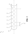
FIG. 1 is a front view of a homogenous LED vehicle lamp, in an embodiment; -
FIG. 2 is a cross-sectional side view of the homogenous LED vehicle lamp ofFIG. 1 ; -
FIG. 3 is a perspective view of a homogenous LED vehicle lamp, in an embodiment; and -
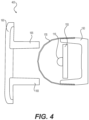
FIG. 4 is a cross-sectional side view of a homogenous LED vehicle lamp, in an embodiment. - A light-emitting diode (LED) produces light when activated by a suitable voltage applied across a semiconductor p-n junction diode. For many illumination applications, light emitted by LEDs may be modified using non-imaging optics such as one or more lenses. However, a disadvantage of using lenses is that a complex system of lenses is typically required to achieve a uniform and homogenous appearing light output from a plurality of LEDs while still meeting output-angle luminance requirements for certain applications. Additional disadvantages of using lenses include a non-contiguous appearance due to the separation of the focal reflectors, and shadowing due to various thicknesses in a typical lens optic.
- Embodiments of the present invention provide a vehicle lamp that uses LEDs as the light source. In certain embodiments, the LED vehicle lamp is a Center-High-Mounted Stop Lamp (CHMSL). CHMSLs are used in passenger cars and light trucks and are required to meet regulations governing luminance, viewing angle, and contrast ratio.
-
FIG. 1 is a front view of an exemplaryhomogenous LED lamp 100. Adiffusion sheet 105 is disposed in front of a plurality of LEDs, such as afirst LED 111, asecond LED 112, athird LED 113, afourth LED 114, afifth LED 115, and asixth LED 116, which are depicted inFIG. 1 with dashed lines to indicate their location behinddiffusion sheet 105.Homogenous LED lamp 100 may include fewer than six or greater than six LEDs without departing from the scope hereof. In certain embodiments, as few as three LEDs may be used, while in other embodiments, greater than fifty LEDs may be used, depending on the length ofhomogenous LED lamp 100 and the intensity of the individual LEDs. - In certain embodiments, first through sixth LEDs 111-116 are arranged in a single string-array of LEDs aligned linearly along a longitudinal axis, marked by a L-L' dashed line in
FIG. 1 . In some embodiments, one or more additional arrays of LEDs may be provided above or below LEDs 111-116 along a transverse axis, marked by a T-T' dashed line, which is perpendicular to the L-L' longitudinal axis. The one or more additional arrays of LEDs may be aligned directly above/below, or offset from, first through sixth LEDs 111-116. - A center-to-
center distance 120 is illustrated inFIG. 1 between C and C' dashed lines corresponding to the distance between the center offirst LED 111 and the center ofsecond LED 112. The center-to-center distance of LEDs 111-116 may be determined based on individual LED properties, such as LED luminance and diameter, as well as a desired light emission profile ofhomogenous LED lamp 100. In some embodiments, the LED diameter is less than 13 mm. In one embodiment, the LED diameter is about 10 mm. In another embodiment, the LED diameter is about 8 mm. In yet another embodiment, the LED diameter is about 5 mm. The light emission profile is based on a cone angle of the LED, which depends on the required prescription (e.g., to meet regulatory requirements), in combination with a preference to prevent or minimize "hot spots". Hot spots are portions of a lamp that appear brighter than other portions. In some embodiments, center-to-center distance 120 is between about 10 mm and 25 mm. In other embodiments, center-to-center distance 120 is between about 10 mm and 15 mm. In one embodiment, center-to-center distance 120 is about 13 mm. -
Diffusion sheet 105 is curved about longitudinal axis L-L'. The radius-of-curvature ofdiffusion sheet 105 about longitudinal axis L-L' is between about 1 mm and 100 mm, and more preferably between about 5 mm and 20 mm. The curvature ofdiffusion sheet 105 may be best viewed from the cross-sectional view provided inFIG. 2 , described below. In certain embodiments, the curvature ofdiffusion sheet 105 bends symmetrically about a midpoint (seeFIG. 2 ). For example,diffusion sheet 105 may have a semi-circular curvature forming a half-cylindrical shape. The material used to formdiffusion sheet 105 may be a transparent or semi-transparent material that smooths uneven light distribution. In an embodiment,diffusion sheet 105 is a Luminit™ light-shaping diffuser (Luminit, LLC. Torrance, CA).Diffusion sheet 105 may be used to smooth light distribution from individual LEDs, such as first through sixth LEDs 111-116, to provide a more uniform and homogenous appearing light source. -
FIG. 2 is a cross-sectional side view ofhomogenous LED lamp 100,FIG. 1 . The cross-sectional view showssixth LED 116 in proximity todiffusion sheet 105.Sixth LED 116 is centrally aligned along a zenith axis, marked by a Z-Z' dashed line inFIG. 2 . In certain embodiments, a midpoint ofdiffusion sheet 105 is aligned with the zenith axis Z-Z', such that a center of curvature ofdiffusion sheet 105 is aligned with a central axis or midpoint ofsixth LED 116.Homogenous LED lamp 100 focuses light output intensity from LEDs 111-116 to create an appearance of smooth homogeneity while meeting functional luminance requirements, as described below. - A maximum intensity of light emitted from
sixth LED 116 occurs along the zenith axis Z-Z'. Light intensity diminishes as an angle of emitted light deviates above or below the zenith axis Z-Z'. A cone of light emitted fromLED 116 may be described as having cone edges, marked as dashed lines E and E' inFIG. 2 , and abeam angle 130, which is an angle between the cone edges. In some embodiments, the cone edges are defined as the portion of light distribution at which fifty percent of the maximum intensity of light is emitted.Beam angle 130 is determined by properties of the LED and may vary from a very narrow spot LED of less than seven degrees to very wide flood LED of more than one-hundred-sixty degrees. In an embodiment,beam angle 130 is about thirty degrees, which sufficiently reduces loss of light per distance away fromsixth LED 116. - Light emitted by first through sixth LEDs 111-116 may be diffused and bent as it passes through
diffusion sheet 105. Specifically, the curvature ofdiffusion sheet 105 contributes to both the appearance and functionality of emitted light by altering the angle of light emitted from LEDs 111-116. For example, light emitted fromsixth LED 116 throughdiffusion sheet 105 may be configured to meet certain luminance requirements including, for example, a ten-degree upward angle and a five-degree downward angle. In certain embodiments,diffusion sheet 105 may be configured to broaden the beam angle compared tobeam angle 130, by bending light output fromsixth LED 116. For example, fifty percent of the maximum intensity of light may emitted at the bent cone edges, marked by B-B' dashed lines inFIG. 2 , instead of at the LED cone edges marked by E-E' dashed lines. - A
distance 140 betweensixth LED 116 anddiffusion sheet 105, which is marked with dashed lines D-D' inFIG. 2 , is adapted for providing the overall desired beam angle and appearance of light emitted fromhomogenous LED lamp 100. In a non-claimed example,distance 140 is about half of the radius of curvature ofdiffusion sheet 105 at the midpoint ofdiffusion sheet 105. In another non-claimed example,distance 140 is between about half of the radius of curvature ofdiffusion sheet 105 to about equal the radius of curvature ofdiffusion sheet 105. -
FIG. 3 is a perspective view of an exemplaryhomogenous LED lamp 300 in operation on a vehicle.Homogenous LED lamp 300 is an example ofhomogenous LED lamp 100,FIG. 1 , configured as a vehicle Center-High-Mounted Stop Lamp (CHMSL). CHMSLs are required by U.S. Federal Motor Vehicle Safety Standard 108 (Code of Federal Regulations, Title 49, Section 571.108) for all passenger cars and light trucks.FIG. 3 illustrates exemplary diffuse light emitted byhomogenous LED lamp 300 in a dark environment. - In some embodiments, a substantially homogeneous appearance from
homogenous LED lamp 300 is provided when viewed from above or below a midpoint of the diffusion sheet by about fifteen degrees (+/- 15°). In other embodiments, the substantially homogenous appearance is provided when viewed from above or below the midpoint by about sixty degrees (+/- 60°). In certain embodiments, a homogeneous appearance is provided when viewinghomogenous LED lamp 300 through an opening of a blackout surface of the rear windshield, while maintaining a maximum contrast ratio of three-to-one (3:1). In some embodiments, the contrast ratio is at least three-to-one. -
FIG. 4 is a cross-sectional side view of an exemplary homogenousLED vehicle lamp 400.First LED 111 is mounted to a printedcircuit board 155 for providing electrical power and control offirst LED 111. Ahousing 150 is used to secure the printedcircuit board 155 anddiffusion sheet 105.First LED 111 anddiffusion sheet 105 are aligned in proximity with a lamp lens, including a transparentouter lens 160 and an opaqueinner lens 165.Outer lens 160 is made of a transparent material configured to protect inner portions oflamp 400 from outside elements while allowing light from thefirst LED 111 to pass through. In certain embodiments,outer lens 160 is a colored transparent lens for creating a colored appearance (e.g., a red lens for a vehicle stop light) from a white light source (e.g., a white LED).Inner lens 165 is made of an opaque material adapted for use as an absorbing element. - In certain embodiments,
diffusion sheet 105 is a hybrid diffusion sheet, which functions partially as a collimator by redirecting at least a portion of the upward and downward light for redirecting wasted light to the beam pattern. For example, at least a portion of light traveling in an upward direction abovefirst LED 111 is redirected downward, and at least a portion of light traveling in a downward direction belowfirst LED 111 is redirected upward. For light traveling horizontally,diffusion sheet 105 works as a diffuser to smooth the light as described above in connection withFIGs. 1-3 . - Advantages of the embodiments of the present disclosure include providing a uniform and homogenous LED light output capable of meeting output angle requirements without needing complex inner lenses.
- Features described above as well as those claimed below may be combined in various ways without departing from the scope of the invention as defined by the appended claims.
- Many different arrangements of the various components depicted, as well as components not shown, are possible without departing from the scope of the present invention as defined in the appended claims. Embodiments of the present invention have been described with the intent to be illustrative rather than restrictive. Alternative embodiments will become apparent to those skilled in the art that do not depart from its scope. A skilled artisan may develop alternative means of implementing the aforementioned improvements without departing from the scope of the present invention.
- It will be understood that certain features and subcombinations are of utility and may be employed without reference to other features and subcombinations and are contemplated within the scope of the claims. Not all operations listed in the various figures need be carried out in the specific order described.
Claims (13)
- A homogeneous light-emitting diode (LED) lamp (100) for an automotive vehicle, comprising:a plurality of LEDs (111 - 116) configured as a LED array, wherein the LED array includes at least one linear array of LEDs aligned linearly along a longitudinal axis (L-L');a diffusion sheet (105) having a curvature aligned with the LED array, wherein the diffusion sheet has a curvature along a transverse axis, perpendicular to the longitudinal axis, such that the diffusion sheet curves around the LED array and extends along the longitudinal axis for smoothing and bending light emitted by the LED array;wherein a first distance is a center-to-center distance (120) between each of the plurality of LEDs, the first distance being between equal to a diameter of each LED to twice the diameter of each LED, and a second distance (140) between the LED array and the diffusion sheet is between half the diameter of each LED to equal the diameter of each LED, andwherein the first distance and the second distance are arranged for the purpose of creating a lighting appearance substantially lacking hotspots.
- The homogeneous LED lamp (100) of claim 1, wherein a LED midpoint of each of the plurality of LEDs is aligned with a midpoint of the diffusion sheet, particularly wherein the curvature of the diffusion sheet is symmetrical about either side of the midpoint of the diffusion sheet.
- The homogeneous LED lamp (100) of claim 1, wherein the curvature of the diffusion sheet has a semi-circular curvature that forms a half-cylindrical shape, or wherein the diffusion sheet bends light emitted from the LED array to a broader cone angle than that of the LED array.
- The homogeneous LED lamp (100) of claim 1, wherein the first distance between each of the plurality of LEDs along the longitudinal axis is between 10 mm to 15 mm.
- The homogeneous LED lamp (100) of claim 1 configured as a vehicle lamp,
wherein the first distance and the second distance are arranged for the purpose of providing a substantially homogenous light output from the vehicle lamp when viewed through the diffusion sheet. - The homogeneous LED lamp (100) of claim 5, wherein each of the plurality of LEDs has a LED midpoint, and the array of LEDs is arranged such that the LED midpoint for each of the plurality of LEDs is aligned with a diffusion sheet midpoint, particularly wherein the diffusion sheet is curved symmetrically about the diffusion sheet midpoint for bending light emitted from the array of LEDs.
- The homogeneous LED lamp (100) of claim 5, wherein the curvature of the diffusion sheet is configured to alter the angle of light emitted from LEDs.
- The homogeneous LED lamp (100) of claim 5, wherein the diffusion sheet is curved to broaden a cone angle of light emitted from the array of LEDs.
- The homogeneous LED lamp (100) of claim 5, wherein the substantially homogenous light output appears substantially homogeneous when viewed from above or below the diffusion sheet midpoint by an angle of up to sixty degrees.
- The homogeneous LED lamp (100) of claim 5, wherein light output intensity from the array of LEDs is focused to create an appearance of smooth homogeneity.
- The homogeneous LED lamp (100) of claim 10, wherein light emitted from LEDs through diffusion sheet includes a ten-degree upward angle and a five-degree downward angle.
- The homogeneous LED lamp (100) of claim 5, wherein a maximum contrast ratio of three-to-one is maintained while viewing the vehicle lamp through an opening of a blackout surface of a rear windshield of a vehicle.
- The homogeneous LED lamp (100) of claim 5, wherein the vehicle lamp is configured to function as a center-high-mounted stop lamp (CHMSL).
Applications Claiming Priority (2)
| Application Number | Priority Date | Filing Date | Title |
|---|---|---|---|
| US201662437906P | 2016-12-22 | 2016-12-22 | |
| PCT/US2017/068086 WO2018119344A1 (en) | 2016-12-22 | 2017-12-22 | Homogenous led vehicle lamp |
Publications (3)
| Publication Number | Publication Date |
|---|---|
| EP3559549A1 EP3559549A1 (en) | 2019-10-30 |
| EP3559549A4 EP3559549A4 (en) | 2020-08-12 |
| EP3559549B1 true EP3559549B1 (en) | 2025-05-28 |
Family
ID=62627926
Family Applications (1)
| Application Number | Title | Priority Date | Filing Date |
|---|---|---|---|
| EP17883053.5A Active EP3559549B1 (en) | 2016-12-22 | 2017-12-22 | Homogenous led vehicle lamp |
Country Status (4)
| Country | Link |
|---|---|
| US (1) | US10443806B2 (en) |
| EP (1) | EP3559549B1 (en) |
| ES (1) | ES3036473T3 (en) |
| WO (1) | WO2018119344A1 (en) |
Families Citing this family (2)
| Publication number | Priority date | Publication date | Assignee | Title |
|---|---|---|---|---|
| US11629832B2 (en) | 2020-06-01 | 2023-04-18 | Flex-N-Gate Advanced Product Development, Llc | Homogenous lit line image vehicle lamp assembly |
| US11506359B2 (en) | 2020-06-01 | 2022-11-22 | Flex-N-Gate Advanced Product Development, Llc | Homogenous lit line image vehicle lamp assembly |
Citations (1)
| Publication number | Priority date | Publication date | Assignee | Title |
|---|---|---|---|---|
| US20050195603A1 (en) * | 2001-10-18 | 2005-09-08 | Ilight Technologies, Inc. | Color-changing illumination device |
Family Cites Families (16)
| Publication number | Priority date | Publication date | Assignee | Title |
|---|---|---|---|---|
| JPH0451404A (en) | 1990-06-18 | 1992-02-19 | Toshihiko Yoshizawa | Dispersion method for high-brightness straight projecting led and car led stop lamp |
| US6592238B2 (en) * | 2001-01-31 | 2003-07-15 | Light Technologies, Inc. | Illumination device for simulation of neon lighting |
| AU2003207854A1 (en) | 2002-02-06 | 2003-09-02 | Schefenacker Vision Systems Usa Inc. | Center high mounted stop lamp including leds and tir lens |
| JP4094366B2 (en) * | 2002-07-24 | 2008-06-04 | 株式会社小糸製作所 | Vehicle lighting |
| US7267466B2 (en) | 2003-08-26 | 2007-09-11 | Valeo Sylvania Llc | Cargo lamp assembly for vehicles |
| KR20090102019A (en) * | 2008-03-25 | 2009-09-30 | 주식회사 엘 앤 에프 | Lighting system for door scuff of vehicles |
| US20120033420A1 (en) * | 2009-04-08 | 2012-02-09 | Sun Woong Kim | Led lamp having broad and uniform light distribution |
| FR2953276B1 (en) * | 2009-11-27 | 2011-11-18 | Peugeot Citroen Automobiles Sa | LIGHTING DEVICE WITH INTERCALE LIGHT GUIDE (S) BETWEEN A REFLECTOR AND A SCREEN |
| JP5538089B2 (en) * | 2010-06-23 | 2014-07-02 | スタンレー電気株式会社 | Vehicle lamp unit |
| US9822951B2 (en) * | 2010-12-06 | 2017-11-21 | Cree, Inc. | LED retrofit lens for fluorescent tube |
| US9194566B2 (en) | 2012-06-08 | 2015-11-24 | Lg Innotek Co., Ltd. | Lamp unit and vehicle lamp apparatus using the same |
| RU134862U1 (en) * | 2013-04-18 | 2013-11-27 | Александр Алексеевич Жаров | CAR LABELS WITH ILLUMINATION (OPTIONS) |
| US9586523B2 (en) * | 2013-11-21 | 2017-03-07 | Ford Global Technologies, Llc | Vehicle lighting assembly |
| US9597998B2 (en) * | 2015-06-15 | 2017-03-21 | GM Global Technology Operations LLC | Light assembly with illuminable outer lens |
| JP6575204B2 (en) * | 2015-07-29 | 2019-09-18 | テイ・エス テック株式会社 | Light emitting device for vehicle |
| DE102015222505A1 (en) * | 2015-11-16 | 2017-05-18 | Bayerische Motoren Werke Aktiengesellschaft | Lighting device for a motor vehicle |
-
2017
- 2017-12-22 ES ES17883053T patent/ES3036473T3/en active Active
- 2017-12-22 EP EP17883053.5A patent/EP3559549B1/en active Active
- 2017-12-22 WO PCT/US2017/068086 patent/WO2018119344A1/en not_active Ceased
- 2017-12-22 US US15/851,880 patent/US10443806B2/en active Active
Patent Citations (1)
| Publication number | Priority date | Publication date | Assignee | Title |
|---|---|---|---|---|
| US20050195603A1 (en) * | 2001-10-18 | 2005-09-08 | Ilight Technologies, Inc. | Color-changing illumination device |
Non-Patent Citations (1)
| Title |
|---|
| ANONYMOUS: "Light Shaping Diffusers (LSDs) | Luminit, LLC", 1 April 2015 (2015-04-01), pages 1 - 3, XP055226304, Retrieved from the Internet <URL:https://web.archive.org/web/20150401074306/http://www.luminitco.com/products/light-shaping-diffusers> [retrieved on 20151105] * |
Also Published As
| Publication number | Publication date |
|---|---|
| ES3036473T3 (en) | 2025-09-19 |
| WO2018119344A1 (en) | 2018-06-28 |
| US20180180244A1 (en) | 2018-06-28 |
| EP3559549A1 (en) | 2019-10-30 |
| EP3559549A4 (en) | 2020-08-12 |
| US10443806B2 (en) | 2019-10-15 |
Similar Documents
| Publication | Publication Date | Title |
|---|---|---|
| US11506358B2 (en) | Optical element, optical module, and vehicle | |
| US10060592B2 (en) | Dual beam pattern vehicular lighting assembly | |
| US11054105B2 (en) | Lamp and vehicle having same | |
| CN108351084B (en) | Lighting device for motor vehicle searchlight | |
| US7762701B2 (en) | Rear-loaded light emitting diode module for automotive rear combination lamps | |
| US7070310B2 (en) | Light emitting diode headlamp | |
| US7988345B2 (en) | Projection module of an automobile headlight | |
| CN110118330B (en) | Vehicle lamps | |
| CN101592303B (en) | Rear loading LED module for motor vehicle rear assembled lamp | |
| US7686481B1 (en) | Illumination apparatus, method, and system for converting pseudo-collimated radiant energy into a predetermined pattern in angle space with controlled intensity | |
| US9851066B2 (en) | Reflector signal lamp having a hidden light source | |
| EP3018401B1 (en) | Vehicle lighting unit | |
| CN102313222A (en) | Vehicular lamp | |
| US9671081B2 (en) | Marker lamp | |
| US20080278961A1 (en) | Hybrid Optics for L.E.D. Lamp | |
| US20090207610A1 (en) | Combination rear lighting system | |
| WO2017075506A1 (en) | Methods and apparatus for intrinsically safe laser sourced illumination | |
| US10443806B2 (en) | Homogenous LED vehicle lamp | |
| EP2179216B1 (en) | Lighting device, in particular light signalling supplementary device for rescue and emergency prioritary vehicles | |
| US9862306B2 (en) | Vehicle decorative lighting device and vehicle lamp | |
| EP3838564A1 (en) | Vehicle lighting fixture | |
| US6851842B2 (en) | Vehicular lamp | |
| US20180023783A1 (en) | Method and apparatus for subtending light downwardly | |
| CN120140681A (en) | Vehicle lighting | |
| CN112351911A (en) | Driving direction indicating device for motor vehicle |
Legal Events
| Date | Code | Title | Description |
|---|---|---|---|
| STAA | Information on the status of an ep patent application or granted ep patent |
Free format text: STATUS: THE INTERNATIONAL PUBLICATION HAS BEEN MADE |
|
| PUAI | Public reference made under article 153(3) epc to a published international application that has entered the european phase |
Free format text: ORIGINAL CODE: 0009012 |
|
| STAA | Information on the status of an ep patent application or granted ep patent |
Free format text: STATUS: REQUEST FOR EXAMINATION WAS MADE |
|
| 17P | Request for examination filed |
Effective date: 20190719 |
|
| AK | Designated contracting states |
Kind code of ref document: A1 Designated state(s): AL AT BE BG CH CY CZ DE DK EE ES FI FR GB GR HR HU IE IS IT LI LT LU LV MC MK MT NL NO PL PT RO RS SE SI SK SM TR |
|
| AX | Request for extension of the european patent |
Extension state: BA ME |
|
| DAV | Request for validation of the european patent (deleted) | ||
| DAX | Request for extension of the european patent (deleted) | ||
| A4 | Supplementary search report drawn up and despatched |
Effective date: 20200715 |
|
| RIC1 | Information provided on ipc code assigned before grant |
Ipc: F21W 107/10 20180101ALI20200709BHEP Ipc: F21S 43/15 20180101ALI20200709BHEP Ipc: F21S 43/20 20180101ALI20200709BHEP Ipc: B60Q 1/30 20060101ALI20200709BHEP Ipc: F21S 43/14 20180101AFI20200709BHEP |
|
| STAA | Information on the status of an ep patent application or granted ep patent |
Free format text: STATUS: EXAMINATION IS IN PROGRESS |
|
| 17Q | First examination report despatched |
Effective date: 20220324 |
|
| RAP3 | Party data changed (applicant data changed or rights of an application transferred) |
Owner name: FLEX-N-GATE ADVANCED PRODUCT DEVELOPMENT, LLC |
|
| GRAP | Despatch of communication of intention to grant a patent |
Free format text: ORIGINAL CODE: EPIDOSNIGR1 |
|
| STAA | Information on the status of an ep patent application or granted ep patent |
Free format text: STATUS: GRANT OF PATENT IS INTENDED |
|
| INTG | Intention to grant announced |
Effective date: 20250217 |
|
| GRAS | Grant fee paid |
Free format text: ORIGINAL CODE: EPIDOSNIGR3 |
|
| GRAA | (expected) grant |
Free format text: ORIGINAL CODE: 0009210 |
|
| STAA | Information on the status of an ep patent application or granted ep patent |
Free format text: STATUS: THE PATENT HAS BEEN GRANTED |
|
| AK | Designated contracting states |
Kind code of ref document: B1 Designated state(s): AL AT BE BG CH CY CZ DE DK EE ES FI FR GB GR HR HU IE IS IT LI LT LU LV MC MK MT NL NO PL PT RO RS SE SI SK SM TR |
|
| REG | Reference to a national code |
Ref country code: GB Ref legal event code: FG4D |
|
| REG | Reference to a national code |
Ref country code: CH Ref legal event code: EP |
|
| REG | Reference to a national code |
Ref country code: IE Ref legal event code: FG4D Ref country code: DE Ref legal event code: R096 Ref document number: 602017089712 Country of ref document: DE |
|
| REG | Reference to a national code |
Ref country code: ES Ref legal event code: FG2A Ref document number: 3036473 Country of ref document: ES Kind code of ref document: T3 Effective date: 20250919 |
|
| REG | Reference to a national code |
Ref country code: NL Ref legal event code: MP Effective date: 20250528 |
|
| PG25 | Lapsed in a contracting state [announced via postgrant information from national office to epo] |
Ref country code: FI Free format text: LAPSE BECAUSE OF FAILURE TO SUBMIT A TRANSLATION OF THE DESCRIPTION OR TO PAY THE FEE WITHIN THE PRESCRIBED TIME-LIMIT Effective date: 20250528 |
|
| REG | Reference to a national code |
Ref country code: LT Ref legal event code: MG9D |
|
| PG25 | Lapsed in a contracting state [announced via postgrant information from national office to epo] |
Ref country code: GR Free format text: LAPSE BECAUSE OF FAILURE TO SUBMIT A TRANSLATION OF THE DESCRIPTION OR TO PAY THE FEE WITHIN THE PRESCRIBED TIME-LIMIT Effective date: 20250829 Ref country code: NO Free format text: LAPSE BECAUSE OF FAILURE TO SUBMIT A TRANSLATION OF THE DESCRIPTION OR TO PAY THE FEE WITHIN THE PRESCRIBED TIME-LIMIT Effective date: 20250828 |
|
| PG25 | Lapsed in a contracting state [announced via postgrant information from national office to epo] |
Ref country code: PL Free format text: LAPSE BECAUSE OF FAILURE TO SUBMIT A TRANSLATION OF THE DESCRIPTION OR TO PAY THE FEE WITHIN THE PRESCRIBED TIME-LIMIT Effective date: 20250528 Ref country code: NL Free format text: LAPSE BECAUSE OF FAILURE TO SUBMIT A TRANSLATION OF THE DESCRIPTION OR TO PAY THE FEE WITHIN THE PRESCRIBED TIME-LIMIT Effective date: 20250528 |
|
| PG25 | Lapsed in a contracting state [announced via postgrant information from national office to epo] |
Ref country code: BG Free format text: LAPSE BECAUSE OF FAILURE TO SUBMIT A TRANSLATION OF THE DESCRIPTION OR TO PAY THE FEE WITHIN THE PRESCRIBED TIME-LIMIT Effective date: 20250528 |
|
| PG25 | Lapsed in a contracting state [announced via postgrant information from national office to epo] |
Ref country code: HR Free format text: LAPSE BECAUSE OF FAILURE TO SUBMIT A TRANSLATION OF THE DESCRIPTION OR TO PAY THE FEE WITHIN THE PRESCRIBED TIME-LIMIT Effective date: 20250528 |
|
| PG25 | Lapsed in a contracting state [announced via postgrant information from national office to epo] |
Ref country code: RS Free format text: LAPSE BECAUSE OF FAILURE TO SUBMIT A TRANSLATION OF THE DESCRIPTION OR TO PAY THE FEE WITHIN THE PRESCRIBED TIME-LIMIT Effective date: 20250828 |
|
| PG25 | Lapsed in a contracting state [announced via postgrant information from national office to epo] |
Ref country code: IS Free format text: LAPSE BECAUSE OF FAILURE TO SUBMIT A TRANSLATION OF THE DESCRIPTION OR TO PAY THE FEE WITHIN THE PRESCRIBED TIME-LIMIT Effective date: 20250928 |
|
| PG25 | Lapsed in a contracting state [announced via postgrant information from national office to epo] |
Ref country code: LV Free format text: LAPSE BECAUSE OF FAILURE TO SUBMIT A TRANSLATION OF THE DESCRIPTION OR TO PAY THE FEE WITHIN THE PRESCRIBED TIME-LIMIT Effective date: 20250528 |
|
| REG | Reference to a national code |
Ref country code: AT Ref legal event code: MK05 Ref document number: 1798759 Country of ref document: AT Kind code of ref document: T Effective date: 20250528 |
|
| PGFP | Annual fee paid to national office [announced via postgrant information from national office to epo] |
Ref country code: GB Payment date: 20251218 Year of fee payment: 9 |
|
| PG25 | Lapsed in a contracting state [announced via postgrant information from national office to epo] |
Ref country code: AT Free format text: LAPSE BECAUSE OF FAILURE TO SUBMIT A TRANSLATION OF THE DESCRIPTION OR TO PAY THE FEE WITHIN THE PRESCRIBED TIME-LIMIT Effective date: 20250528 Ref country code: DK Free format text: LAPSE BECAUSE OF FAILURE TO SUBMIT A TRANSLATION OF THE DESCRIPTION OR TO PAY THE FEE WITHIN THE PRESCRIBED TIME-LIMIT Effective date: 20250528 Ref country code: SM Free format text: LAPSE BECAUSE OF FAILURE TO SUBMIT A TRANSLATION OF THE DESCRIPTION OR TO PAY THE FEE WITHIN THE PRESCRIBED TIME-LIMIT Effective date: 20250528 |
|
| PGFP | Annual fee paid to national office [announced via postgrant information from national office to epo] |
Ref country code: FR Payment date: 20251217 Year of fee payment: 9 |
|
| PG25 | Lapsed in a contracting state [announced via postgrant information from national office to epo] |
Ref country code: CZ Free format text: LAPSE BECAUSE OF FAILURE TO SUBMIT A TRANSLATION OF THE DESCRIPTION OR TO PAY THE FEE WITHIN THE PRESCRIBED TIME-LIMIT Effective date: 20250528 |
|
| PG25 | Lapsed in a contracting state [announced via postgrant information from national office to epo] |
Ref country code: EE Free format text: LAPSE BECAUSE OF FAILURE TO SUBMIT A TRANSLATION OF THE DESCRIPTION OR TO PAY THE FEE WITHIN THE PRESCRIBED TIME-LIMIT Effective date: 20250528 |
|
| PG25 | Lapsed in a contracting state [announced via postgrant information from national office to epo] |
Ref country code: SK Free format text: LAPSE BECAUSE OF FAILURE TO SUBMIT A TRANSLATION OF THE DESCRIPTION OR TO PAY THE FEE WITHIN THE PRESCRIBED TIME-LIMIT Effective date: 20250528 Ref country code: RO Free format text: LAPSE BECAUSE OF FAILURE TO SUBMIT A TRANSLATION OF THE DESCRIPTION OR TO PAY THE FEE WITHIN THE PRESCRIBED TIME-LIMIT Effective date: 20250528 |
|
| PG25 | Lapsed in a contracting state [announced via postgrant information from national office to epo] |
Ref country code: IT Free format text: LAPSE BECAUSE OF FAILURE TO SUBMIT A TRANSLATION OF THE DESCRIPTION OR TO PAY THE FEE WITHIN THE PRESCRIBED TIME-LIMIT Effective date: 20250528 |
|
| REG | Reference to a national code |
Ref country code: DE Ref legal event code: R097 Ref document number: 602017089712 Country of ref document: DE |
|
| PLBE | No opposition filed within time limit |
Free format text: ORIGINAL CODE: 0009261 |
|
| STAA | Information on the status of an ep patent application or granted ep patent |
Free format text: STATUS: NO OPPOSITION FILED WITHIN TIME LIMIT |
|
| REG | Reference to a national code |
Ref country code: CH Ref legal event code: L10 Free format text: ST27 STATUS EVENT CODE: U-0-0-L10-L00 (AS PROVIDED BY THE NATIONAL OFFICE) Effective date: 20260409 |
|
| PGFP | Annual fee paid to national office [announced via postgrant information from national office to epo] |
Ref country code: ES Payment date: 20260122 Year of fee payment: 9 |
|
| PGFP | Annual fee paid to national office [announced via postgrant information from national office to epo] |
Ref country code: DE Payment date: 20251222 Year of fee payment: 9 |
|
| 26N | No opposition filed |
Effective date: 20260303 |