EP3559539B1 - Grease coupler - Google Patents
Grease coupler Download PDFInfo
- Publication number
- EP3559539B1 EP3559539B1 EP18800826.2A EP18800826A EP3559539B1 EP 3559539 B1 EP3559539 B1 EP 3559539B1 EP 18800826 A EP18800826 A EP 18800826A EP 3559539 B1 EP3559539 B1 EP 3559539B1
- Authority
- EP
- European Patent Office
- Prior art keywords
- nozzle
- outer sleeve
- axially
- collar
- sleeve
- Prior art date
- Legal status (The legal status is an assumption and is not a legal conclusion. Google has not performed a legal analysis and makes no representation as to the accuracy of the status listed.)
- Active
Links
Images



Classifications
-
- F—MECHANICAL ENGINEERING; LIGHTING; HEATING; WEAPONS; BLASTING
- F16—ENGINEERING ELEMENTS AND UNITS; GENERAL MEASURES FOR PRODUCING AND MAINTAINING EFFECTIVE FUNCTIONING OF MACHINES OR INSTALLATIONS; THERMAL INSULATION IN GENERAL
- F16N—LUBRICATING
- F16N21/00—Conduits; Junctions; Fittings for lubrication apertures
- F16N21/04—Nozzles for connection of lubricating equipment to nipples
-
- F—MECHANICAL ENGINEERING; LIGHTING; HEATING; WEAPONS; BLASTING
- F16—ENGINEERING ELEMENTS AND UNITS; GENERAL MEASURES FOR PRODUCING AND MAINTAINING EFFECTIVE FUNCTIONING OF MACHINES OR INSTALLATIONS; THERMAL INSULATION IN GENERAL
- F16L—PIPES; JOINTS OR FITTINGS FOR PIPES; SUPPORTS FOR PIPES, CABLES OR PROTECTIVE TUBING; MEANS FOR THERMAL INSULATION IN GENERAL
- F16L37/00—Couplings of the quick-acting type
- F16L37/08—Couplings of the quick-acting type in which the connection between abutting or axially overlapping ends is maintained by locking members
- F16L37/12—Couplings of the quick-acting type in which the connection between abutting or axially overlapping ends is maintained by locking members using hooks, pawls, or other movable or insertable locking members
- F16L37/121—Couplings of the quick-acting type in which the connection between abutting or axially overlapping ends is maintained by locking members using hooks, pawls, or other movable or insertable locking members using freely rocking hooks
-
- F—MECHANICAL ENGINEERING; LIGHTING; HEATING; WEAPONS; BLASTING
- F16—ENGINEERING ELEMENTS AND UNITS; GENERAL MEASURES FOR PRODUCING AND MAINTAINING EFFECTIVE FUNCTIONING OF MACHINES OR INSTALLATIONS; THERMAL INSULATION IN GENERAL
- F16L—PIPES; JOINTS OR FITTINGS FOR PIPES; SUPPORTS FOR PIPES, CABLES OR PROTECTIVE TUBING; MEANS FOR THERMAL INSULATION IN GENERAL
- F16L37/00—Couplings of the quick-acting type
- F16L37/22—Couplings of the quick-acting type in which the connection is maintained by means of balls, rollers or helical springs under radial pressure between the parts
- F16L37/23—Couplings of the quick-acting type in which the connection is maintained by means of balls, rollers or helical springs under radial pressure between the parts by means of balls
-
- F—MECHANICAL ENGINEERING; LIGHTING; HEATING; WEAPONS; BLASTING
- F16—ENGINEERING ELEMENTS AND UNITS; GENERAL MEASURES FOR PRODUCING AND MAINTAINING EFFECTIVE FUNCTIONING OF MACHINES OR INSTALLATIONS; THERMAL INSULATION IN GENERAL
- F16N—LUBRICATING
- F16N3/00—Devices for supplying lubricant by manual action
- F16N3/10—Devices for supplying lubricant by manual action delivering grease
- F16N3/12—Grease guns
Definitions
- the present invention relates to grease couplers.
- Grease couplers connect a grease nipple to pressurised grease from a grease gun.
- the patent US 1 744 305 discloses a nozzle for a grease gun, with automatic locking and easy disconnecting properties, comprising: a sleeve axially movable on a discharge member, both having an inlet end and an outlet end; a nut connected to the inlet end of the discharge member; a sliding sleeve movable on the sleeve between the nut and the inlet end of the sleeve; a spring on the inlet end of the discharge member between the sliding sleeve and the nut to axially bias the sliding sleeve toward the outlet end of the sleeve; locking bars axially and radially movable in the outlet end of the sleeve to lock and unlock with a nipple; a tubular plunger tube axially movable in the outlet end of the discharge member between the locking bars and the outlet end of the discharge member; a coiled spring in the discharge member between the tubular plunger tube and the nut; the grease
- a grease coupler comprising:
- the outlet end of the outer sleeve may have an inwardly inclined lip, wherein the jaws are axially and radially movable against the inwardly inclined lip to lock and unlock with the grease nipple.
- a nozzle flange may extend radially from the nozzle to axially move the jaws toward the inwardly inclined lip at the outlet end of the outer sleeve.
- a pair of finger grips may extend radially from the collar to axially move the collar axially away from the outlet end of the outer sleeve.
- a ball check valve may be provided in the connection body.
- the ball check valve may be an adjustable ball check valve.
- the present invention also provides a method, comprising positively coupling and uncoupling a grease nipple to pressurised grease from a grease gun using the grease coupler described above.
- a grease coupler 10 may generally comprise an outer sleeve 12, an actuation collar 14, and a connection body 16.
- a pair of finger grips 18 may extend radially from the collar 14 to axially move the collar 14 axially away from an outlet end of the outer sleeve 12.
- the connection body 16 may be threadingly connectable to a grease gun hose (not shown).
- Clamping jaws 20 may be provided in an outlet end of the outer sleeve 12 to lock and unlock with a grease nipple, for example, a Zerk nipple (not shown).
- the finger grips 18 may be a moulding of suitable plastics materials, while the remaining components may be formed from suitable metals or metal alloys unless stated otherwise.
- the outer sleeve 12 may be axially movable on an inner sleeve 22.
- the outer sleeve 12 and the inner sleeve 22 may each have an inlet end and an outlet end.
- the connection body 16 may be threadingly connected to the inlet end of the inner sleeve 22.
- the collar 14 may be axially movable on the outer sleeve 12 between the connection body 16 and the inlet end of the outer sleeve 12.
- a collar spring 24 may be provided on the inlet end of the inner sleeve 22 between the collar 14 and the connection body 16 to axially bias the collar 14 toward the outlet end of the outer sleeve 22.
- the jaws 20 may be axially and radially movable in the outlet end of the outer sleeve 12 to lock and unlock with a grease nipple 26.
- the outlet end of the outer sleeve 12 may have an inwardly inclined lip 28, and the jaws 20 may be axially and radially movable against the inwardly inclined lip 28 to lock and unlock with the grease nipple 26.
- the jaws 20 may comprise three jaws 20 spaced circumferentially around 120° from one another each other in a floating configuration for gripping the grease nipple 26. This configuration advantageously provides maximum grip surface, and lower and more even contact stress on grease nipples 26 to avoid damaging them.
- the three-floating configuration of the jaws 20 is more versatile and conforms better to standardised shapes, sizes and tolerances of grease nipples 26 (eg, SAE J534, BS1486 and DIN71412 applicable standards). This is advantageous as grease nipples 26 are no longer machined for cost reasons, and hence are not as dimensionally accurate and consistent as they used to be.
- grease nipples 26 eg, SAE J534, BS1486 and DIN71412 applicable standards.
- a nozzle 30 may be axially movable in the outlet end of the outer sleeve 12 between the jaws 20 and the outlet end of the inner sleeve 22.
- the connection body 16, the inner sleeve 22, the outer sleeve 12, the nozzle 30 may collectively define a flow passage for pressurised grease from the grease gun hose to the grease nipple 26.
- a nozzle spring 32 may be provided in the inner sleeve 22 between the nozzle 30 and the connection body 16.
- a rubber nozzle seal 34 may be provided in the nozzle 30.
- a nozzle flange 36 may extend radially from the nozzle 30 to axially move the jaws 20 toward the inwardly inclined lip 28 at the outlet end of the outer sleeve 12.
- a collar ball groove 38 may be formed in the collar 14, and a corresponding inner ball groove 40 may be formed in the inner sleeve 22.
- Sleeve locking balls 42 may be axially and radially movable between the collar ball groove 38 and the inner ball groove 40 via ball holes 44 formed in the outer sleeve 12.
- a nozzle ball groove 46 defining a limited axial distance may be formed in the nozzle 30.
- Nozzle locking balls 48 may be provided in the outlet end of the inner sleeve 22 to be axially movable within the limited axial distance defined by the nozzle ball groove 46.
- the nozzle locking balls 48 may be axially retained by a retaining ring 50 and a snap ring (or circlip) 52.
- An O-ring 54 may be provided in an O-ring groove on the inner sleeve 22 axially inward of the nozzle.
- a ball check valve 56 may be provided in the connection body 16.
- the ball check valves 56 may comprise a valve spring 58, a valve ball 60 and an adjustable valve seat ring 62 that provides selectively adjustable limitation of pressurised grease flow from the grease gun hose after disconnection.
- a first retraction of the collar 14 axially away from the outlet end of the outer sleeve 12 pre-arms the grease coupler 10 for coupling to the grease nipple 26 by axially and radially moving the sleeve locking balls 42 from the collar ball groove 38 to the inner ball groove 40 to lock the outer sleeve 12 and the inner sleeve 22 to one another to thereby permit relative axial movement between the outer sleeve 12 and the nozzle 30 to lock the jaws 20.
- the collar 14 is axially biased back toward the outlet end of the outer sleeve 12 by the collar spring 24. This leaves the grease collar 10 pre-armed and ready to positively couple to the grease nipple 26, as illustrated in Figure 6 .
- a second retraction of the collar 14 axially away from the outlet end of the outer sleeve 12 moves the sleeve locking balls 42 from the inner ball groove 40 back into the collar ball groove 38 to unlock the outer sleeve 12 and the inner sleeve 22 from one another to thereby permit relative axial movement between the outer sleeve 12 and the nozzle 30 to unlock the jaws 20 from the grease nipple 26, while relative axial movement between the nozzle 30 and the inner sleeve 22 is limited by the nozzle locking balls 48 axially moving within the limited axial distance defined by the nozzle ball groove 46 to positively uncouple the nozzle 30 from the grease nipple 26.
- the positive nozzle retention provided by the nozzle ball groove 46 and the nozzle locking balls 48 during uncoupling may overcome any hydraulic lock between the grease nipple 26 and the nozzle 30 from build-up of back pressure inside the grease coupler 10.
- Embodiments of the present invention provide grease couplers that are useful for positively coupling and uncoupling grease nipples to pressurised grease from grease guns, while avoiding or minimising leaking or back spurting of grease.
Landscapes
- Engineering & Computer Science (AREA)
- General Engineering & Computer Science (AREA)
- Mechanical Engineering (AREA)
- Quick-Acting Or Multi-Walled Pipe Joints (AREA)
Description
- The present invention relates to grease couplers.
- Grease couplers connect a grease nipple to pressurised grease from a grease gun.
- Conventional couplers suffer from several drawbacks. It is difficult to positively couple and uncouple the coupler and the nipple, particularly under high grease pressure. This requires noticeable physical effort and also leads to wear and tear, or even failure of the components. The lack of positive coupling and uncoupling also leads to leaking of grease, or even spurting of high pressure grease back onto an operator. Furthermore, build-up of back pressure inside the coupler can lead to the formation of hydraulic lock which prevents positive uncoupling of the coupler and the nipple. Most conventional quick-release couplers are bulky which poses problems of access to tight greasing points.
- The patent
US 1 744 305 discloses a nozzle for a grease gun, with automatic locking and easy disconnecting properties, comprising: a sleeve axially movable on a discharge member, both having an inlet end and an outlet end; a nut connected to the inlet end of the discharge member; a sliding sleeve movable on the sleeve between the nut and the inlet end of the sleeve; a spring on the inlet end of the discharge member between the sliding sleeve and the nut to axially bias the sliding sleeve toward the outlet end of the sleeve; locking bars axially and radially movable in the outlet end of the sleeve to lock and unlock with a nipple; a tubular plunger tube axially movable in the outlet end of the discharge member between the locking bars and the outlet end of the discharge member; a coiled spring in the discharge member between the tubular plunger tube and the nut; the grease coupler being locked with or disconnected from a grease nipple (or fitting) by drawing the sleeve rearward. - In this context, there is a need for improved grease couplers.
- According to the present invention, there is provided a grease coupler, comprising:
- an outer sleeve axially movable on an inner sleeve, each of which has an inlet end and an outlet end; a connection body connected to the inlet end of the inner sleeve;
- a collar axially movable on the outer sleeve between the connection body and the inlet end of the outer sleeve; a collar spring on the inlet end of the inner sleeve between the collar and the connection body to axially bias the collar toward the outlet end of the outer sleeve;
- jaws axially and radially movable in the outlet end of the outer sleeve to lock and unlock with a grease nipple;
- a nozzle axially movable in the outlet end of the outer sleeve between the jaws and the outlet end of the inner sleeve;
- a nozzle spring in the inner sleeve between the nozzle and the connection body;
- a collar ball groove in the collar and a corresponding inner ball groove in the inner sleeve;
- sleeve locking balls axially and radially movable between the collar ball groove and the inner ball groove via ball holes in the outer sleeve;
- a nozzle ball groove in the nozzle; and
- nozzle locking balls in the outlet end of the inner sleeve and axially movable within a limited axial distance defined by the nozzle ball groove;
- wherein a first retraction of the collar axially away from the outlet end of the outer sleeve pre-arms the grease coupler for coupling to the grease nipple by axially and radially moving the sleeve locking balls from the collar ball groove to the inner ball groove to lock the outer sleeve and the inner sleeve to one another to thereby permit relative axial movement between the outer sleeve and the nozzle to lock the jaws;
- wherein pushing the grease nipple inside the outlet end of the outer sleeve initially moves the nozzle axially away from the jaws to unlock the jaws and compress the nozzle spring, and subsequently moves the nozzle axially toward the grease nipple under spring pressure by the nozzle spring to thereby relock the jaws and positively couple the nozzle to the grease nipple; and
- wherein a second retraction of the collar axially away from the outlet end of the outer sleeve moves the sleeve locking balls from the inner ball groove to the collar ball groove to unlock the outer sleeve and the inner sleeve from one another to thereby permit relative axial movement between the outer sleeve and the nozzle to thereby unlock the jaws from the grease nipple, while relative axial movement between the nozzle and the inner sleeve is limited by axial movement of the nozzle locking balls within the limited axial distance defined by the nozzle ball groove to thereby positively uncouple the nozzle from the grease nipple.
- The outlet end of the outer sleeve may have an inwardly inclined lip, wherein the jaws are axially and radially movable against the inwardly inclined lip to lock and unlock with the grease nipple.
- A nozzle flange may extend radially from the nozzle to axially move the jaws toward the inwardly inclined lip at the outlet end of the outer sleeve.
- A pair of finger grips may extend radially from the collar to axially move the collar axially away from the outlet end of the outer sleeve.
- A ball check valve may be provided in the connection body.
- The ball check valve may be an adjustable ball check valve.
- The present invention also provides a method, comprising positively coupling and uncoupling a grease nipple to pressurised grease from a grease gun using the grease coupler described above.
- Embodiments of the invention will now be described by way of example only with reference to the accompanying drawings, in which:
-
Figures 1 and 2 are perspective front and rear views of a grease coupler according to an embodiment of the present invention; -
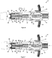
Figure 3 is a section view of the grease coupler in an uncoupled state; -
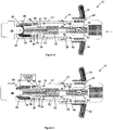
Figures 4 to 6 are sequential section views showing pre-arming of the grease coupler for coupling with a grease nipple; -
Figures 7 to 9 are sequential section views showing positive coupling of the grease coupler to the grease nipple; and -
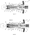
Figures 10 to 13 are sequential section views showing positive uncoupling of the grease coupler from the grease nipple. - Referring to
Figures 1 and 2 , agrease coupler 10 according to an embodiment of the present invention may generally comprise anouter sleeve 12, anactuation collar 14, and aconnection body 16. A pair offinger grips 18 may extend radially from thecollar 14 to axially move thecollar 14 axially away from an outlet end of theouter sleeve 12. Theconnection body 16 may be threadingly connectable to a grease gun hose (not shown). Clampingjaws 20 may be provided in an outlet end of theouter sleeve 12 to lock and unlock with a grease nipple, for example, a Zerk nipple (not shown). Thefinger grips 18 may be a moulding of suitable plastics materials, while the remaining components may be formed from suitable metals or metal alloys unless stated otherwise. - Referring to
Figure 3 , theouter sleeve 12 may be axially movable on aninner sleeve 22. Theouter sleeve 12 and theinner sleeve 22 may each have an inlet end and an outlet end. Theconnection body 16 may be threadingly connected to the inlet end of theinner sleeve 22. Thecollar 14 may be axially movable on theouter sleeve 12 between theconnection body 16 and the inlet end of theouter sleeve 12. Acollar spring 24 may be provided on the inlet end of theinner sleeve 22 between thecollar 14 and theconnection body 16 to axially bias thecollar 14 toward the outlet end of theouter sleeve 22. - The
jaws 20 may be axially and radially movable in the outlet end of theouter sleeve 12 to lock and unlock with agrease nipple 26. The outlet end of theouter sleeve 12 may have an inwardlyinclined lip 28, and thejaws 20 may be axially and radially movable against the inwardlyinclined lip 28 to lock and unlock with thegrease nipple 26. Thejaws 20 may comprise threejaws 20 spaced circumferentially around 120° from one another each other in a floating configuration for gripping thegrease nipple 26. This configuration advantageously provides maximum grip surface, and lower and more even contact stress ongrease nipples 26 to avoid damaging them. In comparison to four jaws spaced circumferentially around 90° from one another, the three-floating configuration of thejaws 20 is more versatile and conforms better to standardised shapes, sizes and tolerances of grease nipples 26 (eg, SAE J534, BS1486 and DIN71412 applicable standards). This is advantageous asgrease nipples 26 are no longer machined for cost reasons, and hence are not as dimensionally accurate and consistent as they used to be. - A
nozzle 30 may be axially movable in the outlet end of theouter sleeve 12 between thejaws 20 and the outlet end of theinner sleeve 22. Theconnection body 16, theinner sleeve 22, theouter sleeve 12, thenozzle 30 may collectively define a flow passage for pressurised grease from the grease gun hose to thegrease nipple 26. Anozzle spring 32 may be provided in theinner sleeve 22 between thenozzle 30 and theconnection body 16. Arubber nozzle seal 34 may be provided in thenozzle 30. Anozzle flange 36 may extend radially from thenozzle 30 to axially move thejaws 20 toward the inwardlyinclined lip 28 at the outlet end of theouter sleeve 12. - A
collar ball groove 38 may be formed in thecollar 14, and a correspondinginner ball groove 40 may be formed in theinner sleeve 22.Sleeve locking balls 42 may be axially and radially movable between thecollar ball groove 38 and theinner ball groove 40 viaball holes 44 formed in theouter sleeve 12. - A
nozzle ball groove 46 defining a limited axial distance may be formed in thenozzle 30.Nozzle locking balls 48 may be provided in the outlet end of theinner sleeve 22 to be axially movable within the limited axial distance defined by thenozzle ball groove 46. Thenozzle locking balls 48 may be axially retained by a retainingring 50 and a snap ring (or circlip) 52. An O-ring 54 may be provided in an O-ring groove on theinner sleeve 22 axially inward of the nozzle. - A ball check valve 56 may be provided in the
connection body 16. The ball check valves 56 may comprise avalve spring 58, avalve ball 60 and an adjustablevalve seat ring 62 that provides selectively adjustable limitation of pressurised grease flow from the grease gun hose after disconnection. - Referring to
Figure 4 , a first retraction of thecollar 14 axially away from the outlet end of theouter sleeve 12 pre-arms thegrease coupler 10 for coupling to thegrease nipple 26 by axially and radially moving thesleeve locking balls 42 from thecollar ball groove 38 to theinner ball groove 40 to lock theouter sleeve 12 and theinner sleeve 22 to one another to thereby permit relative axial movement between theouter sleeve 12 and thenozzle 30 to lock thejaws 20. As illustrated inFigure 5 , after the first retraction, thecollar 14 is axially biased back toward the outlet end of theouter sleeve 12 by thecollar spring 24. This leaves thegrease collar 10 pre-armed and ready to positively couple to thegrease nipple 26, as illustrated inFigure 6 . - Referring to
Figure 7 , pushing thegrease nipple 26 inside the outlet end of theouter sleeve 12 initially moves thenozzle 30 axially away from thejaws 20 to unlock thejaws 20 and compress thenozzle spring 32. As illustrated inFigure 8 , thenozzle 30 is subsequently moved axially toward thegrease nipple 26 under spring pressure by thenozzle spring 32 to thereby relock thejaws 20 and positively couple thenozzle 30 to thegrease nipple 26. This leaves thegrease coupler 10 in a positively coupled state with the grease nipple, as illustrated inFigure 9 , to allow pressurised grease to be supplied from the grease gun hose to thegrease nipple 26. - Referring to
Figures 10 to 13 , a second retraction of thecollar 14 axially away from the outlet end of theouter sleeve 12 moves thesleeve locking balls 42 from theinner ball groove 40 back into thecollar ball groove 38 to unlock theouter sleeve 12 and theinner sleeve 22 from one another to thereby permit relative axial movement between theouter sleeve 12 and thenozzle 30 to unlock thejaws 20 from thegrease nipple 26, while relative axial movement between thenozzle 30 and theinner sleeve 22 is limited by thenozzle locking balls 48 axially moving within the limited axial distance defined by thenozzle ball groove 46 to positively uncouple thenozzle 30 from thegrease nipple 26. The positive nozzle retention provided by thenozzle ball groove 46 and thenozzle locking balls 48 during uncoupling may overcome any hydraulic lock between thegrease nipple 26 and thenozzle 30 from build-up of back pressure inside thegrease coupler 10. - Embodiments of the present invention provide grease couplers that are useful for positively coupling and uncoupling grease nipples to pressurised grease from grease guns, while avoiding or minimising leaking or back spurting of grease.
- For the purpose of this specification, the word "comprising" means "including but not limited to," and the word "comprises" has a corresponding meaning.
- The above embodiments have been described by way of example only and modifications are possible within the scope of the claims that follow.
Claims (7)
- A grease coupler (10), comprising:an outer sleeve (12) axially movable on an inner sleeve (22), each of which has an inlet end and an outlet end;a connection body (16) connected to the inlet end of the inner sleeve (22);a collar (14) axially movable on the outer sleeve (12) between the connection body (16) and the inlet end of the outer sleeve (12);a collar spring (24) on the inlet end of the inner sleeve (22) between the collar (14) and the connection body (16) to axially bias the collar (14) toward the outlet end of the outer sleeve (22);jaws (20) axially and radially movable in the outlet end of the outer sleeve (12) to lock and unlock with a grease nipple (26);a nozzle (30) axially movable in the outlet end of the inner sleeve (22) between the jaws (20) and the outlet end of the inner sleeve (22);a nozzle spring (32) in the inner sleeve (22) between the nozzle (30) and the connection body (16);characterized in that it comprises:a collar ball groove (38) in the collar (14) and a corresponding inner ball groove (40) in the inner sleeve (22);sleeve locking balls (42) axially and radially movable between the collar ball groove (38) and the inner ball groove (40) via ball holes (44) in the outer sleeve (12);a nozzle ball groove (46) in the nozzle (30); andnozzle locking balls (48) in the outlet end of the inner sleeve (22) and axially movable within a limited axial distance defined by the nozzle ball groove (46);wherein a first retraction of the collar (14) axially away from the outlet end of the outer sleeve (12) pre-arms the grease coupler (10) for coupling to the grease nipple (26) by axially and radially moving the sleeve locking balls (42) from the collar ball groove (38) to the inner ball groove (40) to lock the outer sleeve (12) and the inner sleeve (22) to one another to thereby permit relative axial movement between the outer sleeve (12) and the nozzle (30) to lock the jaws (20);wherein pushing the grease nipple (26) inside the outlet end of the outer sleeve (12) initially moves the nozzle (30) axially away from the jaws (20) to unlock the jaws (20) and compress the nozzle spring (32), and subsequently moves the nozzle (30) axially toward the grease nipple (26) under spring pressure by the nozzle spring (32) to thereby relock the jaws (20) and positively couple the nozzle (30) to the grease nipple (26); andwherein a second retraction of the collar (14) axially away from the outlet end of the outer sleeve (12) moves the sleeve locking balls (42) from the inner ball groove (40) to the collar ball groove (38) to unlock the outer sleeve (12) and the inner sleeve (22) from one another to thereby permit relative axial movement between the outer sleeve (12) and the nozzle (30) to thereby unlock the jaws (20) from the grease nipple (26), while relative axial movement between the nozzle (30) and the inner sleeve (22) is limited by axial movement of the nozzle locking balls (48) within the limited axial distance defined by the nozzle ball groove (46) to thereby positively uncouple the nozzle (30) from the grease nipple (26).
- The coupler of claim 1 , wherein the outlet end of the outer sleeve (12) has an inwardly inclined lip (28), and wherein the jaws (20) arranged in a floating configuration are axially and radially movable against the inwardly inclined lip (28) to lock and unlock with the grease nipple (26).
- The coupler of claim 2, wherein a nozzle flange (36) may extend radially from the nozzle (30) to axially move the jaws (20) toward the inwardly inclined lip (28) at the outlet end of the outer sleeve (12).
- The coupler of claim 1, wherein a pair of finger grips (18) extend radially from the collar (14) to axially move the collar (14) axially away from the outlet end of the outer sleeve (12).
- The coupler of claim 1, wherein a ball check valve (56) is provided in the connection body (16).
- The coupler of claim 5, wherein the ball check valve (56) is an adjustable ball check valve.
- A method, comprising positively coupling and uncoupling a grease nipple (26) to pressurised grease from a grease gun using the grease coupler of claim 1.
Applications Claiming Priority (2)
| Application Number | Priority Date | Filing Date | Title |
|---|---|---|---|
| AU2017902478A AU2017902478A0 (en) | 2017-06-27 | Grease couplers | |
| PCT/AU2018/050651 WO2019000035A1 (en) | 2017-06-27 | 2018-06-27 | Grease coupler |
Publications (3)
| Publication Number | Publication Date |
|---|---|
| EP3559539A1 EP3559539A1 (en) | 2019-10-30 |
| EP3559539A4 EP3559539A4 (en) | 2020-02-26 |
| EP3559539B1 true EP3559539B1 (en) | 2022-05-04 |
Family
ID=64740283
Family Applications (1)
| Application Number | Title | Priority Date | Filing Date |
|---|---|---|---|
| EP18800826.2A Active EP3559539B1 (en) | 2017-06-27 | 2018-06-27 | Grease coupler |
Country Status (12)
| Country | Link |
|---|---|
| US (1) | US10865940B1 (en) |
| EP (1) | EP3559539B1 (en) |
| JP (1) | JP7184802B2 (en) |
| CN (1) | CN110914584B (en) |
| AU (1) | AU2018256611B1 (en) |
| BR (1) | BR112019023959B1 (en) |
| MX (1) | MX2019014125A (en) |
| NZ (1) | NZ747968A (en) |
| RU (1) | RU2761297C2 (en) |
| TW (1) | TWI763872B (en) |
| WO (1) | WO2019000035A1 (en) |
| ZA (1) | ZA201807394B (en) |
Cited By (1)
| Publication number | Priority date | Publication date | Assignee | Title |
|---|---|---|---|---|
| DE102024130256A1 (en) | 2024-10-17 | 2026-04-23 | Rudolf Schlenker | Coupling for connection to a nipple |
Families Citing this family (1)
| Publication number | Priority date | Publication date | Assignee | Title |
|---|---|---|---|---|
| CN119321527B (en) * | 2024-10-23 | 2025-11-07 | 宝武杰富意特殊钢有限公司 | Grease filling device and grease filling method |
Family Cites Families (44)
| Publication number | Priority date | Publication date | Assignee | Title |
|---|---|---|---|---|
| US1744305A (en) | 1928-02-03 | 1930-01-21 | Charles L Gannaway | Nozzle for grease guns |
| US1796827A (en) * | 1928-03-26 | 1931-03-17 | Alemite Corp | Grease-gun coupling |
| US2104146A (en) * | 1928-12-31 | 1938-01-04 | Adams Grease Gun Corp | Lubricating apparatus |
| US2056249A (en) * | 1934-01-22 | 1936-10-06 | Stewart Warner Corp | Lubricating apparatus |
| US2070013A (en) * | 1935-04-29 | 1937-02-09 | Min A Max Co Inc | Lubricating apparatus |
| US2274651A (en) * | 1939-04-05 | 1942-03-03 | Lincoln Eng Co | Coupler |
| US2311097A (en) * | 1941-10-17 | 1943-02-16 | Edwin P Sundholm | Multijawed chuck-type hydraulic snap-on coupler |
| US2362880A (en) * | 1942-10-24 | 1944-11-14 | Stewart Warner Corp | Coupler |
| US2400817A (en) * | 1942-12-17 | 1946-05-21 | Lincoln Eng Co | Lubricant-receiving fitting |
| US2397342A (en) * | 1944-03-18 | 1946-03-26 | Universal Lubricating Systems | Lubricant-carrying means |
| US2396499A (en) * | 1944-03-22 | 1946-03-12 | Aro Equipment Corp | Coupler |
| US2425692A (en) * | 1944-08-19 | 1947-08-12 | Balcrank Inc | Coupler |
| US2714021A (en) * | 1950-03-21 | 1955-07-26 | So Called Tecalemit Sa Soc | Pressure-lubricating devices |
| GB695656A (en) | 1950-03-21 | 1953-08-12 | Tecalemit Ltd | A coupling device for use in pressure lubrication |
| US2764769A (en) * | 1950-07-10 | 1956-10-02 | Neuman Chaim Jakob | Coupling for pressure lubricating devices |
| US2754135A (en) | 1951-01-05 | 1956-07-10 | Kramer Richard | Rapid pipe coupling with means to prevent seal blowout |
| US2784987A (en) | 1954-02-03 | 1957-03-12 | Corcoran Richard Stanley | Pipe coupling with detent means |
| GB792710A (en) * | 1955-05-02 | 1958-04-02 | Chaim Jakob Neuman | Improvements in or relating to couplings for lubricators |
| US3421792A (en) * | 1966-02-02 | 1969-01-14 | Edwin P Sundholm | Angularly adjustable coupler assembly |
| US3464436A (en) | 1967-09-05 | 1969-09-02 | Earl F Bruning | Self-cleaning fluid coupling |
| US3589673A (en) * | 1968-06-20 | 1971-06-29 | Foster Mfg Co Inc | Fluid line coupling |
| US3589470A (en) * | 1969-09-24 | 1971-06-29 | Superior Mfg Co | Grease gun adapter |
| US3788427A (en) * | 1972-06-09 | 1974-01-29 | Wheelabrator Frye Inc | Grease gun and coupling |
| US3779586A (en) | 1972-08-10 | 1973-12-18 | D Rossiter | Hose coupling connect and disconnect mechanism |
| US4195812A (en) * | 1977-12-27 | 1980-04-01 | Thexton Manufacturing Company | Coupler for grease guns |
| SE440138B (en) | 1982-07-27 | 1985-07-15 | Karl Ove Nyberg | Pneumatic |
| US4607727A (en) * | 1985-03-18 | 1986-08-26 | Jochum Vincent F | Grease zerk ram |
| JPH0234556Y2 (en) * | 1985-12-28 | 1990-09-17 | ||
| SE506405C2 (en) * | 1996-03-22 | 1997-12-15 | Nyberg Bo Erik | Quick release with pressure relief for safe release |
| JP3002168B2 (en) * | 1998-01-09 | 2000-01-24 | ナスコフィッティング株式会社 | Pipe fittings |
| FR2786848B1 (en) * | 1998-12-02 | 2001-02-09 | Legris Sa | BALL COUPLER |
| AU2002306959B2 (en) | 2001-03-27 | 2006-06-29 | Invacare Corporation | Rapid connection coupling |
| US6675833B2 (en) | 2002-02-04 | 2004-01-13 | Parker-Hannifin Corporation | Connect under pressure coupling |
| CN2577096Y (en) * | 2002-10-18 | 2003-10-01 | 程虎 | A pressurized butter flat nozzle |
| US6776187B1 (en) * | 2003-03-06 | 2004-08-17 | Parker-Hannifin Corporation | Quick coupling with pressure assist piston |
| MX338955B (en) * | 2009-12-01 | 2016-05-06 | Gurtech Pty Ltd | An improved grease coupler. |
| US8303000B2 (en) * | 2010-09-13 | 2012-11-06 | Liu Hsiu-Hsiung | Quick release connector |
| US8720487B2 (en) | 2010-10-19 | 2014-05-13 | Robert Charles Cooley | Grease delivery receiver and nozzle couplable without fluid pressure bleed-down and having pressurization lockout and flush face coupling |
| CA2869435A1 (en) * | 2012-05-29 | 2013-12-05 | Y&D Brothers Innovations Inc. | Grease gun coupler |
| RU2531067C1 (en) * | 2013-04-01 | 2014-10-20 | Леонид Васильевич Соболев | Tip for input of portions of grease lubricant |
| CA2948936C (en) * | 2014-05-12 | 2022-05-03 | Alfa Gomma S.P.A. | Quick coupling engageable under pressure |
| CN205350812U (en) * | 2016-02-02 | 2016-06-29 | 阳江核电有限公司 | Fuel filler neck device |
| WO2018109777A1 (en) * | 2016-12-12 | 2018-06-21 | Groz Engineering Tools (P) Ltd. | A coupling device |
| TWM545862U (en) * | 2017-04-12 | 2017-07-21 | King Cho Machinery Industrial Co Ltd | Connector structure of grease gun |
-
2018
- 2018-06-27 NZ NZ747968A patent/NZ747968A/en unknown
- 2018-06-27 WO PCT/AU2018/050651 patent/WO2019000035A1/en not_active Ceased
- 2018-06-27 TW TW107122180A patent/TWI763872B/en active
- 2018-06-27 JP JP2019560650A patent/JP7184802B2/en active Active
- 2018-06-27 CN CN201880040518.4A patent/CN110914584B/en active Active
- 2018-06-27 US US16/300,376 patent/US10865940B1/en active Active
- 2018-06-27 EP EP18800826.2A patent/EP3559539B1/en active Active
- 2018-06-27 RU RU2019142513A patent/RU2761297C2/en active
- 2018-06-27 MX MX2019014125A patent/MX2019014125A/en unknown
- 2018-06-27 BR BR112019023959-6A patent/BR112019023959B1/en active IP Right Grant
- 2018-06-27 AU AU2018256611A patent/AU2018256611B1/en active Active
- 2018-11-05 ZA ZA201807394A patent/ZA201807394B/en unknown
Cited By (2)
| Publication number | Priority date | Publication date | Assignee | Title |
|---|---|---|---|---|
| DE102024130256A1 (en) | 2024-10-17 | 2026-04-23 | Rudolf Schlenker | Coupling for connection to a nipple |
| WO2026082703A1 (en) | 2024-10-17 | 2026-04-23 | Rudolf Schlenker | Coupling for coupling to a lubricating nipple |
Also Published As
| Publication number | Publication date |
|---|---|
| JP7184802B2 (en) | 2022-12-06 |
| EP3559539A4 (en) | 2020-02-26 |
| WO2019000035A1 (en) | 2019-01-03 |
| CA3062096A1 (en) | 2019-01-03 |
| MX2019014125A (en) | 2020-07-29 |
| TWI763872B (en) | 2022-05-11 |
| RU2019142513A3 (en) | 2021-11-11 |
| EP3559539A1 (en) | 2019-10-30 |
| BR112019023959B1 (en) | 2023-11-21 |
| AU2018256611B1 (en) | 2019-01-17 |
| BR112019023959A2 (en) | 2020-06-09 |
| RU2019142513A (en) | 2021-07-27 |
| NZ747968A (en) | 2024-10-25 |
| US10865940B1 (en) | 2020-12-15 |
| ZA201807394B (en) | 2019-11-27 |
| US20200393081A1 (en) | 2020-12-17 |
| RU2761297C2 (en) | 2021-12-06 |
| CN110914584A (en) | 2020-03-24 |
| TW201904796A (en) | 2019-02-01 |
| JP2020525715A (en) | 2020-08-27 |
| CN110914584B (en) | 2021-09-14 |
Similar Documents
| Publication | Publication Date | Title |
|---|---|---|
| US2860893A (en) | Ball detent type coupling with break-away feature | |
| US8807525B2 (en) | Quick-release coupling | |
| US20090140519A1 (en) | Quick connect tubular coupling | |
| US20190120413A1 (en) | A coupling device | |
| US4221235A (en) | Quick disconnect coupling | |
| US6283151B1 (en) | Rigid mount, breakaway coupling | |
| EP0916057A1 (en) | Coupling device for rapid connection | |
| EP0804701A1 (en) | Rapid connection coupling | |
| US11002406B2 (en) | Coupling for pressure lines | |
| US20150115601A1 (en) | Grease gun coupler | |
| AU2017266442B2 (en) | Fluid coupling assembly | |
| US10865940B1 (en) | Grease coupler | |
| CN107917296B (en) | Quick coupler | |
| CA3062096C (en) | Grease coupler | |
| US7537246B2 (en) | Pipe coupler | |
| US6688655B1 (en) | Quick connection-release coupling | |
| EP3807566B1 (en) | Quick coupling joining kit for irrigation hoses | |
| JP2002514728A (en) | Connector with safety release device | |
| GB2435913A (en) | Air line safety coupling with venting position | |
| WO2000004316A1 (en) | Quick-acting coupling for fluid transporting pipes | |
| WO2020129793A1 (en) | Pipe-joint size adjustment attachment | |
| EP3244115B1 (en) | Kit comprising a plurality of male couplings with an integrated shunt system for achieving a shunt function on the movable side of a multi-coupling device and multi-coupling device comprising said kit |
Legal Events
| Date | Code | Title | Description |
|---|---|---|---|
| STAA | Information on the status of an ep patent application or granted ep patent |
Free format text: STATUS: UNKNOWN |
|
| STAA | Information on the status of an ep patent application or granted ep patent |
Free format text: STATUS: THE INTERNATIONAL PUBLICATION HAS BEEN MADE |
|
| PUAI | Public reference made under article 153(3) epc to a published international application that has entered the european phase |
Free format text: ORIGINAL CODE: 0009012 |
|
| STAA | Information on the status of an ep patent application or granted ep patent |
Free format text: STATUS: REQUEST FOR EXAMINATION WAS MADE |
|
| 17P | Request for examination filed |
Effective date: 20181123 |
|
| AK | Designated contracting states |
Kind code of ref document: A1 Designated state(s): AL AT BE BG CH CY CZ DE DK EE ES FI FR GB GR HR HU IE IS IT LI LT LU LV MC MK MT NL NO PL PT RO RS SE SI SK SM TR |
|
| AX | Request for extension of the european patent |
Extension state: BA ME |
|
| A4 | Supplementary search report drawn up and despatched |
Effective date: 20200123 |
|
| RIC1 | Information provided on ipc code assigned before grant |
Ipc: F16N 3/12 20060101ALI20200117BHEP Ipc: F16N 21/04 20060101AFI20200117BHEP Ipc: F16L 37/23 20060101ALI20200117BHEP Ipc: F16L 37/00 20060101ALI20200117BHEP |
|
| DAV | Request for validation of the european patent (deleted) | ||
| DAX | Request for extension of the european patent (deleted) | ||
| GRAP | Despatch of communication of intention to grant a patent |
Free format text: ORIGINAL CODE: EPIDOSNIGR1 |
|
| STAA | Information on the status of an ep patent application or granted ep patent |
Free format text: STATUS: GRANT OF PATENT IS INTENDED |
|
| INTG | Intention to grant announced |
Effective date: 20211126 |
|
| RIN1 | Information on inventor provided before grant (corrected) |
Inventor name: SINGH, PRABHJOT Inventor name: UCCELLANI, MARCO |
|
| GRAS | Grant fee paid |
Free format text: ORIGINAL CODE: EPIDOSNIGR3 |
|
| GRAA | (expected) grant |
Free format text: ORIGINAL CODE: 0009210 |
|
| STAA | Information on the status of an ep patent application or granted ep patent |
Free format text: STATUS: THE PATENT HAS BEEN GRANTED |
|
| AK | Designated contracting states |
Kind code of ref document: B1 Designated state(s): AL AT BE BG CH CY CZ DE DK EE ES FI FR GB GR HR HU IE IS IT LI LT LU LV MC MK MT NL NO PL PT RO RS SE SI SK SM TR |
|
| REG | Reference to a national code |
Ref country code: GB Ref legal event code: FG4D |
|
| REG | Reference to a national code |
Ref country code: CH Ref legal event code: EP |
|
| REG | Reference to a national code |
Ref country code: AT Ref legal event code: REF Ref document number: 1489393 Country of ref document: AT Kind code of ref document: T Effective date: 20220515 |
|
| REG | Reference to a national code |
Ref country code: IE Ref legal event code: FG4D Ref country code: DE Ref legal event code: R096 Ref document number: 602018035080 Country of ref document: DE |
|
| REG | Reference to a national code |
Ref country code: LT Ref legal event code: MG9D |
|
| REG | Reference to a national code |
Ref country code: NL Ref legal event code: MP Effective date: 20220504 |
|
| REG | Reference to a national code |
Ref country code: AT Ref legal event code: MK05 Ref document number: 1489393 Country of ref document: AT Kind code of ref document: T Effective date: 20220504 |
|
| PG25 | Lapsed in a contracting state [announced via postgrant information from national office to epo] |
Ref country code: SE Free format text: LAPSE BECAUSE OF FAILURE TO SUBMIT A TRANSLATION OF THE DESCRIPTION OR TO PAY THE FEE WITHIN THE PRESCRIBED TIME-LIMIT Effective date: 20220504 Ref country code: PT Free format text: LAPSE BECAUSE OF FAILURE TO SUBMIT A TRANSLATION OF THE DESCRIPTION OR TO PAY THE FEE WITHIN THE PRESCRIBED TIME-LIMIT Effective date: 20220905 Ref country code: NO Free format text: LAPSE BECAUSE OF FAILURE TO SUBMIT A TRANSLATION OF THE DESCRIPTION OR TO PAY THE FEE WITHIN THE PRESCRIBED TIME-LIMIT Effective date: 20220804 Ref country code: NL Free format text: LAPSE BECAUSE OF FAILURE TO SUBMIT A TRANSLATION OF THE DESCRIPTION OR TO PAY THE FEE WITHIN THE PRESCRIBED TIME-LIMIT Effective date: 20220504 Ref country code: LT Free format text: LAPSE BECAUSE OF FAILURE TO SUBMIT A TRANSLATION OF THE DESCRIPTION OR TO PAY THE FEE WITHIN THE PRESCRIBED TIME-LIMIT Effective date: 20220504 Ref country code: HR Free format text: LAPSE BECAUSE OF FAILURE TO SUBMIT A TRANSLATION OF THE DESCRIPTION OR TO PAY THE FEE WITHIN THE PRESCRIBED TIME-LIMIT Effective date: 20220504 Ref country code: GR Free format text: LAPSE BECAUSE OF FAILURE TO SUBMIT A TRANSLATION OF THE DESCRIPTION OR TO PAY THE FEE WITHIN THE PRESCRIBED TIME-LIMIT Effective date: 20220805 Ref country code: FI Free format text: LAPSE BECAUSE OF FAILURE TO SUBMIT A TRANSLATION OF THE DESCRIPTION OR TO PAY THE FEE WITHIN THE PRESCRIBED TIME-LIMIT Effective date: 20220504 Ref country code: ES Free format text: LAPSE BECAUSE OF FAILURE TO SUBMIT A TRANSLATION OF THE DESCRIPTION OR TO PAY THE FEE WITHIN THE PRESCRIBED TIME-LIMIT Effective date: 20220504 Ref country code: BG Free format text: LAPSE BECAUSE OF FAILURE TO SUBMIT A TRANSLATION OF THE DESCRIPTION OR TO PAY THE FEE WITHIN THE PRESCRIBED TIME-LIMIT Effective date: 20220804 Ref country code: AT Free format text: LAPSE BECAUSE OF FAILURE TO SUBMIT A TRANSLATION OF THE DESCRIPTION OR TO PAY THE FEE WITHIN THE PRESCRIBED TIME-LIMIT Effective date: 20220504 |
|
| PG25 | Lapsed in a contracting state [announced via postgrant information from national office to epo] |
Ref country code: RS Free format text: LAPSE BECAUSE OF FAILURE TO SUBMIT A TRANSLATION OF THE DESCRIPTION OR TO PAY THE FEE WITHIN THE PRESCRIBED TIME-LIMIT Effective date: 20220504 Ref country code: PL Free format text: LAPSE BECAUSE OF FAILURE TO SUBMIT A TRANSLATION OF THE DESCRIPTION OR TO PAY THE FEE WITHIN THE PRESCRIBED TIME-LIMIT Effective date: 20220504 Ref country code: LV Free format text: LAPSE BECAUSE OF FAILURE TO SUBMIT A TRANSLATION OF THE DESCRIPTION OR TO PAY THE FEE WITHIN THE PRESCRIBED TIME-LIMIT Effective date: 20220504 Ref country code: IS Free format text: LAPSE BECAUSE OF FAILURE TO SUBMIT A TRANSLATION OF THE DESCRIPTION OR TO PAY THE FEE WITHIN THE PRESCRIBED TIME-LIMIT Effective date: 20220904 |
|
| PG25 | Lapsed in a contracting state [announced via postgrant information from national office to epo] |
Ref country code: SM Free format text: LAPSE BECAUSE OF FAILURE TO SUBMIT A TRANSLATION OF THE DESCRIPTION OR TO PAY THE FEE WITHIN THE PRESCRIBED TIME-LIMIT Effective date: 20220504 Ref country code: SK Free format text: LAPSE BECAUSE OF FAILURE TO SUBMIT A TRANSLATION OF THE DESCRIPTION OR TO PAY THE FEE WITHIN THE PRESCRIBED TIME-LIMIT Effective date: 20220504 Ref country code: RO Free format text: LAPSE BECAUSE OF FAILURE TO SUBMIT A TRANSLATION OF THE DESCRIPTION OR TO PAY THE FEE WITHIN THE PRESCRIBED TIME-LIMIT Effective date: 20220504 Ref country code: EE Free format text: LAPSE BECAUSE OF FAILURE TO SUBMIT A TRANSLATION OF THE DESCRIPTION OR TO PAY THE FEE WITHIN THE PRESCRIBED TIME-LIMIT Effective date: 20220504 Ref country code: DK Free format text: LAPSE BECAUSE OF FAILURE TO SUBMIT A TRANSLATION OF THE DESCRIPTION OR TO PAY THE FEE WITHIN THE PRESCRIBED TIME-LIMIT Effective date: 20220504 Ref country code: CZ Free format text: LAPSE BECAUSE OF FAILURE TO SUBMIT A TRANSLATION OF THE DESCRIPTION OR TO PAY THE FEE WITHIN THE PRESCRIBED TIME-LIMIT Effective date: 20220504 |
|
| REG | Reference to a national code |
Ref country code: CH Ref legal event code: PL |
|
| REG | Reference to a national code |
Ref country code: DE Ref legal event code: R097 Ref document number: 602018035080 Country of ref document: DE |
|
| REG | Reference to a national code |
Ref country code: BE Ref legal event code: MM Effective date: 20220630 |
|
| PG25 | Lapsed in a contracting state [announced via postgrant information from national office to epo] |
Ref country code: MC Free format text: LAPSE BECAUSE OF FAILURE TO SUBMIT A TRANSLATION OF THE DESCRIPTION OR TO PAY THE FEE WITHIN THE PRESCRIBED TIME-LIMIT Effective date: 20220504 |
|
| PLBE | No opposition filed within time limit |
Free format text: ORIGINAL CODE: 0009261 |
|
| STAA | Information on the status of an ep patent application or granted ep patent |
Free format text: STATUS: NO OPPOSITION FILED WITHIN TIME LIMIT |
|
| PG25 | Lapsed in a contracting state [announced via postgrant information from national office to epo] |
Ref country code: AL Free format text: LAPSE BECAUSE OF FAILURE TO SUBMIT A TRANSLATION OF THE DESCRIPTION OR TO PAY THE FEE WITHIN THE PRESCRIBED TIME-LIMIT Effective date: 20220504 |
|
| 26N | No opposition filed |
Effective date: 20230207 |
|
| PG25 | Lapsed in a contracting state [announced via postgrant information from national office to epo] |
Ref country code: LU Free format text: LAPSE BECAUSE OF NON-PAYMENT OF DUE FEES Effective date: 20220627 Ref country code: LI Free format text: LAPSE BECAUSE OF NON-PAYMENT OF DUE FEES Effective date: 20220630 Ref country code: IE Free format text: LAPSE BECAUSE OF NON-PAYMENT OF DUE FEES Effective date: 20220627 Ref country code: CH Free format text: LAPSE BECAUSE OF NON-PAYMENT OF DUE FEES Effective date: 20220630 |
|
| PG25 | Lapsed in a contracting state [announced via postgrant information from national office to epo] |
Ref country code: SI Free format text: LAPSE BECAUSE OF FAILURE TO SUBMIT A TRANSLATION OF THE DESCRIPTION OR TO PAY THE FEE WITHIN THE PRESCRIBED TIME-LIMIT Effective date: 20220504 Ref country code: BE Free format text: LAPSE BECAUSE OF NON-PAYMENT OF DUE FEES Effective date: 20220630 |
|
| P01 | Opt-out of the competence of the unified patent court (upc) registered |
Effective date: 20230514 |
|
| PG25 | Lapsed in a contracting state [announced via postgrant information from national office to epo] |
Ref country code: IT Free format text: LAPSE BECAUSE OF FAILURE TO SUBMIT A TRANSLATION OF THE DESCRIPTION OR TO PAY THE FEE WITHIN THE PRESCRIBED TIME-LIMIT Effective date: 20220504 |
|
| PG25 | Lapsed in a contracting state [announced via postgrant information from national office to epo] |
Ref country code: HU Free format text: LAPSE BECAUSE OF FAILURE TO SUBMIT A TRANSLATION OF THE DESCRIPTION OR TO PAY THE FEE WITHIN THE PRESCRIBED TIME-LIMIT; INVALID AB INITIO Effective date: 20180627 |
|
| PG25 | Lapsed in a contracting state [announced via postgrant information from national office to epo] |
Ref country code: MK Free format text: LAPSE BECAUSE OF FAILURE TO SUBMIT A TRANSLATION OF THE DESCRIPTION OR TO PAY THE FEE WITHIN THE PRESCRIBED TIME-LIMIT Effective date: 20220504 Ref country code: CY Free format text: LAPSE BECAUSE OF FAILURE TO SUBMIT A TRANSLATION OF THE DESCRIPTION OR TO PAY THE FEE WITHIN THE PRESCRIBED TIME-LIMIT Effective date: 20220504 |
|
| PG25 | Lapsed in a contracting state [announced via postgrant information from national office to epo] |
Ref country code: TR Free format text: LAPSE BECAUSE OF FAILURE TO SUBMIT A TRANSLATION OF THE DESCRIPTION OR TO PAY THE FEE WITHIN THE PRESCRIBED TIME-LIMIT Effective date: 20220504 |
|
| PG25 | Lapsed in a contracting state [announced via postgrant information from national office to epo] |
Ref country code: MT Free format text: LAPSE BECAUSE OF FAILURE TO SUBMIT A TRANSLATION OF THE DESCRIPTION OR TO PAY THE FEE WITHIN THE PRESCRIBED TIME-LIMIT Effective date: 20220504 |
|
| PG25 | Lapsed in a contracting state [announced via postgrant information from national office to epo] |
Ref country code: BG Free format text: LAPSE BECAUSE OF FAILURE TO SUBMIT A TRANSLATION OF THE DESCRIPTION OR TO PAY THE FEE WITHIN THE PRESCRIBED TIME-LIMIT Effective date: 20220504 |
|
| PG25 | Lapsed in a contracting state [announced via postgrant information from national office to epo] |
Ref country code: BG Free format text: LAPSE BECAUSE OF FAILURE TO SUBMIT A TRANSLATION OF THE DESCRIPTION OR TO PAY THE FEE WITHIN THE PRESCRIBED TIME-LIMIT Effective date: 20220504 |
|
| PGFP | Annual fee paid to national office [announced via postgrant information from national office to epo] |
Ref country code: DE Payment date: 20250620 Year of fee payment: 8 |
|
| PGFP | Annual fee paid to national office [announced via postgrant information from national office to epo] |
Ref country code: GB Payment date: 20250619 Year of fee payment: 8 |
|
| PGFP | Annual fee paid to national office [announced via postgrant information from national office to epo] |
Ref country code: FR Payment date: 20250619 Year of fee payment: 8 |