EP3558767B1 - Lever assembly - Google Patents
Lever assembly Download PDFInfo
- Publication number
- EP3558767B1 EP3558767B1 EP17826565.8A EP17826565A EP3558767B1 EP 3558767 B1 EP3558767 B1 EP 3558767B1 EP 17826565 A EP17826565 A EP 17826565A EP 3558767 B1 EP3558767 B1 EP 3558767B1
- Authority
- EP
- European Patent Office
- Prior art keywords
- lever
- support
- tooth
- seat
- cover
- Prior art date
- Legal status (The legal status is an assumption and is not a legal conclusion. Google has not performed a legal analysis and makes no representation as to the accuracy of the status listed.)
- Active
Links
Images



Classifications
-
- B—PERFORMING OPERATIONS; TRANSPORTING
- B60—VEHICLES IN GENERAL
- B60T—VEHICLE BRAKE CONTROL SYSTEMS OR PARTS THEREOF; BRAKE CONTROL SYSTEMS OR PARTS THEREOF, IN GENERAL; ARRANGEMENT OF BRAKING ELEMENTS ON VEHICLES IN GENERAL; PORTABLE DEVICES FOR PREVENTING UNWANTED MOVEMENT OF VEHICLES; VEHICLE MODIFICATIONS TO FACILITATE COOLING OF BRAKES
- B60T7/00—Brake-action initiating means
- B60T7/02—Brake-action initiating means for personal initiation
- B60T7/08—Brake-action initiating means for personal initiation hand actuated
-
- B—PERFORMING OPERATIONS; TRANSPORTING
- B62—LAND VEHICLES FOR TRAVELLING OTHERWISE THAN ON RAILS
- B62K—CYCLES; CYCLE FRAMES; CYCLE STEERING DEVICES; RIDER-OPERATED TERMINAL CONTROLS SPECIALLY ADAPTED FOR CYCLES; CYCLE AXLE SUSPENSIONS; CYCLE SIDECARS, FORECARS, OR THE LIKE
- B62K23/00—Rider-operated controls specially adapted for cycles, i.e. means for initiating control operations, e.g. levers, grips
- B62K23/02—Rider-operated controls specially adapted for cycles, i.e. means for initiating control operations, e.g. levers, grips hand actuated
- B62K23/06—Levers
-
- B—PERFORMING OPERATIONS; TRANSPORTING
- B62—LAND VEHICLES FOR TRAVELLING OTHERWISE THAN ON RAILS
- B62L—BRAKES SPECIALLY ADAPTED FOR CYCLES
- B62L3/00—Brake-actuating mechanisms; Arrangements thereof
- B62L3/02—Brake-actuating mechanisms; Arrangements thereof for control by a hand lever
- B62L3/023—Brake-actuating mechanisms; Arrangements thereof for control by a hand lever acting on fluid pressure systems
-
- B—PERFORMING OPERATIONS; TRANSPORTING
- B60—VEHICLES IN GENERAL
- B60T—VEHICLE BRAKE CONTROL SYSTEMS OR PARTS THEREOF; BRAKE CONTROL SYSTEMS OR PARTS THEREOF, IN GENERAL; ARRANGEMENT OF BRAKING ELEMENTS ON VEHICLES IN GENERAL; PORTABLE DEVICES FOR PREVENTING UNWANTED MOVEMENT OF VEHICLES; VEHICLE MODIFICATIONS TO FACILITATE COOLING OF BRAKES
- B60T11/00—Transmitting braking action from initiating means to ultimate brake actuator without power assistance or drive or where such assistance or drive is irrelevant
- B60T11/10—Transmitting braking action from initiating means to ultimate brake actuator without power assistance or drive or where such assistance or drive is irrelevant transmitting by fluid means, e.g. hydraulic
- B60T11/16—Master control, e.g. master cylinders
Definitions
- the present invention relates to a lever assembly, in particular a lever assembly for vehicles controlled by means of a handle, such as, for example, motor vehicles and or snowmobiles.
- control levers e.g. for braking systems or for clutches, which are easy to be constructed and assembled, are increasingly required.
- Known solutions are disclosed in US-4850241 , CN-201961485 , DE807064 e WO-2014-040248
- Figure 1 shows a local section of a lever assembly according to a first prior art, where the pin, which forms the rotation hinge element of the lever with respect to its support, is received in through seats and connected in a use position due to the extension thereof, or head, which rests on the body of the support.
- This known pin remains in the work position due to the inclusion, at its opposite end with respect to the head, of a Seeger ring, or elastic ring, which prevents the pin from exiting the seats.
- This known pin is made by means of molding and the seat made therein for the elastic element, or Seeger ring, is obtained by means of mechanical processing.
- this known solution also requires an automatic assembly system, which allows the Seeger to be inserted into its seat, thus preventing the accidental exit of the pin.
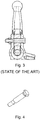
- Figure 3 depicts a local section of a further solution according to the prior art.
- the pin always has an enlarged head and a stem with a threaded end portion protruding from the seats of the lever and the support thereof for engaging a locking nut.
- Figure 4 shows an axonometric view of this known pin.
- the thread is obtained by mechanical processing and involves the use of special equipment for tightening the locking nut of the pin with predetermined tightening torques to prevent the accidental unscrewing of the nut and the exit of the pin.
- a lever assembly 1 comprises a control lever 2 having at least one lever coupling portion 3 delimiting a lever rotation seat 4.
- Said assembly also comprises a lever support 5 comprising at least one support tooth 6; 7. Said at least one support tooth 6; 7 delimits a tooth seat 8; 9.
- Said assembly also comprises an articulation pin 10 received in said tooth seat 8; 9 of at least one support tooth 6; 7 and also received in said lever rotation seat 4 for the rotation of the control lever 2 with respect to said lever support 5.
- Said lever assembly 1 advantageously comprises at least one cover 11 connected to said lever support 5, which at least partially closes at least one of said tooth seat 8 and said rotation seat 4, to prevent the pin 10 from exiting said seats 4, 8 and rotatably constrain the lever 2 to the support 5.
- said control lever 2 comprises a grasping portion 12 adapted to be grasped by at least one finger of a driver.
- said control lever 2 comprises a pump control extension 13 adapted to act in conjunction with a pump 14 for actuating a brake or clutch.
- said control lever 2 comprises a microswitch control extension 15 adapted to act in conjunction with a microswitch 16 to signal the actuation of the control lever 2.
- said lever support 5 comprises two teeth, a support tooth 6 and a through tooth 7. Said two teeth 6, 7 form said tooth seat 8 and a through tooth seat 9, respectively.
- said lever coupling portion 3 is received between said two teeth 6, 7 so as to align said rotation seat 4 with said tooth seat 8 and through tooth seat 9 for receiving said articulation pin 10 in said seats 8, 4, 9.
- said lever support 5 comprises a pump body 17.
- said lever support 5 is made in one body, or one piece, with said pump body 17.
- said lever support 5 comprises a tank 18 for supplying fluid to a pump body 17.
- said lever support 5 is made in one body, or one piece, with said tank 18.
- said lever support 5 comprises a support-handle connecting portion 19 adapted to connect said support 5 to a handle of a vehicle.
- said at least one support tooth 6; 7, which delimits a tooth seat 8; 9, comprises an insertion seat end 20 and an opposite abutment seat end 21.
- said opposite abutment seat end 21 comprises a tooth support surface 22, which allows the articulation pin 10 to be supported so as to prevent it from exiting the side opposite to the insertion seat end 20, or the side opposite to said cover 11 placed on the insertion side.
- said opposite abutment seat end 21 comprises a maneuvering opening 23, which prevents the pin 10 from exiting, but allows a tool to extract the pin from the seats 4, 8; 9 when the cover 11 is removed.
- said articulation pin 10 comprises a first end support surface 24, which rests on a tooth support surface 22, which allows the articulation pin 10 to be supported so as to prevent it from exiting the side opposite to said cover 11 and the insertion side.
- said articulation pin 10 comprises a second end support surface 25, which rests on a cover support surface 26, which allows to block the articulation pin 10 in the seats 4, 8; 9, so as to prevent it from exiting when said cover 11 is connected in place to the support 5.
- said articulation pin 10 comprises a body having a main longitudinal extension and a constant transverse size.
- said articulation pin 10 comprises a cylindrical-shaped body.
- said articulation pin 10 is obtained from a bar.
- said cover 11 is in one piece with a tank cover 27 adapted to close a tank 18.
- said cover 11 is connected to the lever support 5 by threaded means.
- said cover 11 is connected to the tank 27 by threaded means.
- said cover 11 comprises a cover support surface 26, which acts in conjunction with a second end support surface 25 of the pin 10, thus blocking said pin 10 received in said rotation seat 4 of the lever 2 and in said tooth seat 8 of said support tooth 6, thus rotatably constraining said lever 2 to said support 5.
- said cover 11 completely closes said at least one of said tooth seat 8 and said rotation seat 4.
- This method incudes the steps of:
- a method of disassembling a lever assembly 1 is described below.
- This method includes the steps of:
- a through hole is present in the support body of the tooth, so that the pin is pushed by a tool to be removed from the seat.
Landscapes
- Engineering & Computer Science (AREA)
- Mechanical Engineering (AREA)
- Transportation (AREA)
- Physics & Mathematics (AREA)
- Fluid Mechanics (AREA)
- Mechanical Control Devices (AREA)
- Transmission Of Braking Force In Braking Systems (AREA)
- Braking Elements And Transmission Devices (AREA)
- Hydraulic Clutches, Magnetic Clutches, Fluid Clutches, And Fluid Joints (AREA)
- Details And Applications Of Rotary Liquid Pumps (AREA)
Description
- The present invention relates to a lever assembly, in particular a lever assembly for vehicles controlled by means of a handle, such as, for example, motor vehicles and or snowmobiles.
- As known, control levers, e.g. for braking systems or for clutches, which are easy to be constructed and assembled, are increasingly required. Known solutions are disclosed in
US-4850241 ,CN-201961485 ,DE807064 eWO-2014-040248 -
Figure 1 shows a local section of a lever assembly according to a first prior art, where the pin, which forms the rotation hinge element of the lever with respect to its support, is received in through seats and connected in a use position due to the extension thereof, or head, which rests on the body of the support. - This known pin remains in the work position due to the inclusion, at its opposite end with respect to the head, of a Seeger ring, or elastic ring, which prevents the pin from exiting the seats.
- This known pin, as can be seen from
figure 2 , is made by means of molding and the seat made therein for the elastic element, or Seeger ring, is obtained by means of mechanical processing. - Therefore, besides being particularly laborious to be achieved, this known solution also requires an automatic assembly system, which allows the Seeger to be inserted into its seat, thus preventing the accidental exit of the pin.
- Furthermore, this known solution leaves many parts of the molded pin in sight, which molded pin is often galvanized due to wear and aesthetics problems, for example. Should the galvanizing have flaws during the assembly step, it would be necessary to discard the pin simply for aesthetic reasons, forcing a pin sorting station to be introduced into the assembly line.
-
Figure 3 depicts a local section of a further solution according to the prior art. - In this known solution, the pin always has an enlarged head and a stem with a threaded end portion protruding from the seats of the lever and the support thereof for engaging a locking nut.
-
Figure 4 shows an axonometric view of this known pin. - In this known solution, in which the pin is molded, the thread is obtained by mechanical processing and involves the use of special equipment for tightening the locking nut of the pin with predetermined tightening torques to prevent the accidental unscrewing of the nut and the exit of the pin.
- Therefore, the need is strongly felt to simplify the construction of the known lever assembly solutions reducing the number of details, better protecting the device, and in particular the articulation pin, as well as reducing the assembly complexity and aesthetic problems.
- It is therefore an object of the present invention to overcome the drawbacks of the prior art and offer a solution to the need to provide a lever assembly, which is easy to be constructed and especially reliable.
- This and other objects are achieved by a lever assembly according to
claim 1, and by the assembly and disassembly method inclaims - Further features and advantages of the lever assembly according to the invention will become apparent from the description of preferred embodiments thereof, given below by way of not limiting example, with reference to the accompanying drawings, in which:
-
figure 1 is a local section view of a solution according to the prior art; -
figure 2 shows an axonometric view of a detail of the pin of the solution infigure 1 of the prior art; -
figure 3 depicts a local section of a second solution according to the prior art; -
figure 4 depicts an axonometric view of a pin of the solution infigure 3 of the prior art; -
figure 5 depicts an axonometric view of a lever assembly according to the invention, along with a pump and a tank; -
figure 6 depicts an axonometric view of the assembly and pump body and tank infigure 5 according to a further point of view; -
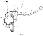
figure 7 depicts a top view of the solution infigure 5 ; -
figure 8 depicts a local section according to line A-A infigure 7 ; -
figure 9 depicts the solution infigure 5 in axonometry and with separated parts; -
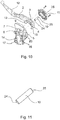
figure 10 depicts an axonometric view of the assembly infigure 5 according to a further point of view; -
figure 11 depicts an axonometric view of a pin of the lever assembly according to the invention. - With reference to the drawings, a lever assembly is shown by
numeral reference 1. - According to a general embodiment, a
lever assembly 1 comprises acontrol lever 2 having at least onelever coupling portion 3 delimiting alever rotation seat 4. - Said assembly also comprises a
lever support 5 comprising at least onesupport tooth 6; 7. Said at least onesupport tooth 6; 7 delimits atooth seat 8; 9. - Said assembly also comprises an
articulation pin 10 received in saidtooth seat 8; 9 of at least onesupport tooth 6; 7 and also received in saidlever rotation seat 4 for the rotation of thecontrol lever 2 with respect to saidlever support 5. - Said
lever assembly 1 advantageously comprises at least onecover 11 connected to saidlever support 5, which at least partially closes at least one of saidtooth seat 8 and saidrotation seat 4, to prevent thepin 10 from exiting saidseats lever 2 to thesupport 5. - According to one embodiment, in addition to the at least one
coupling portion 3, saidcontrol lever 2 comprises agrasping portion 12 adapted to be grasped by at least one finger of a driver. - According to one embodiment, said
control lever 2 comprises apump control extension 13 adapted to act in conjunction with apump 14 for actuating a brake or clutch. - According to one embodiment, said
control lever 2 comprises amicroswitch control extension 15 adapted to act in conjunction with amicroswitch 16 to signal the actuation of thecontrol lever 2. - According to one embodiment, said
lever support 5 comprises two teeth, asupport tooth 6 and a throughtooth 7. Said twoteeth tooth seat 8 and a throughtooth seat 9, respectively. - According to one embodiment, said
lever coupling portion 3 is received between said twoteeth rotation seat 4 with saidtooth seat 8 and throughtooth seat 9 for receiving saidarticulation pin 10 in saidseats - According to one embodiment, said
lever support 5 comprises apump body 17. - According to one embodiment, said
lever support 5 is made in one body, or one piece, with saidpump body 17. - According to one embodiment, said
lever support 5 comprises atank 18 for supplying fluid to apump body 17. - According to one embodiment, said
lever support 5 is made in one body, or one piece, with saidtank 18. - According to one embodiment, said
lever support 5 comprises a support-handle connecting portion 19 adapted to connect saidsupport 5 to a handle of a vehicle. - According to the invention, said at least one
support tooth 6; 7, which delimits atooth seat 8; 9, comprises aninsertion seat end 20 and an oppositeabutment seat end 21. - According to the invention, said opposite
abutment seat end 21 comprises atooth support surface 22, which allows thearticulation pin 10 to be supported so as to prevent it from exiting the side opposite to theinsertion seat end 20, or the side opposite to saidcover 11 placed on the insertion side. - According to the invention, said opposite
abutment seat end 21 comprises amaneuvering opening 23, which prevents thepin 10 from exiting, but allows a tool to extract the pin from theseats cover 11 is removed. - According to one embodiment, said
articulation pin 10 comprises a firstend support surface 24, which rests on atooth support surface 22, which allows thearticulation pin 10 to be supported so as to prevent it from exiting the side opposite to saidcover 11 and the insertion side. - According to one embodiment, said
articulation pin 10 comprises a secondend support surface 25, which rests on acover support surface 26, which allows to block thearticulation pin 10 in theseats cover 11 is connected in place to thesupport 5. - According to one embodiment, said
articulation pin 10 comprises a body having a main longitudinal extension and a constant transverse size. - According to one embodiment, said
articulation pin 10 comprises a cylindrical-shaped body. - According to one embodiment, said
articulation pin 10 is obtained from a bar. - According to one embodiment, said
cover 11 is in one piece with a tank cover 27 adapted to close atank 18. - According to one embodiment, said
cover 11 is connected to thelever support 5 by threaded means. - According to one embodiment, said
cover 11 is connected to the tank 27 by threaded means. - According to one embodiment, said
cover 11 comprises acover support surface 26, which acts in conjunction with a secondend support surface 25 of thepin 10, thus blocking saidpin 10 received in saidrotation seat 4 of thelever 2 and in saidtooth seat 8 of saidsupport tooth 6, thus rotatably constraining saidlever 2 to saidsupport 5. - According to one embodiment, said
cover 11 completely closes said at least one of saidtooth seat 8 and saidrotation seat 4. - A method of assembling or disassembling a
lever assembly 1 will be described below. - This method incudes the steps of:
- providing a
lever assembly 1 as described in any one of the above-listed embodiments; - aligning said
rotation seat 4 of saidcontrol lever 2 with saidtooth seat 8 of thesupport tooth 6; - inserting said
articulation pin 10; - connecting said
cover 11 to saidlever support 5 at least partially closing at least one of saidtooth seat 8 androtation seat 4, and preventing thepin 10 from exiting saidseats lever 2 to thesupport 5. - A method of disassembling a
lever assembly 1 is described below. - This method includes the steps of:
- providing a maneuvering opening 23 as defined in any one of the above-listed embodiments;
- removing said
cover 11; - inserting a tool into said maneuvering opening 23 removing the
articulation pin 11 from saidtooth seat 8 androtation seat 4; - removing the
lever coupling portion 3 from saidsupport tooth 6 by removing saidcontrol lever 2 from saidlever support 5. - Due to the described embodiments, it is possible to simplify the construction of the lever assembly, for example it is possible to eliminate the component which avoids the removal of the pin (the Seeger in
figure 1 or the nut infigure 3 ) making the cover perform this function, e.g. the tank cover. - For example, it is possible to make a pin obtained from a bar. This rests on the tooth seat of the support and is contained by the cover.
- According to a particular disassembly method, in order to facilitate the removal of the pin, a through hole is present in the support body of the tooth, so that the pin is pushed by a tool to be removed from the seat.
- Some of the advantages of these assembly solutions as described above are:
- elimination of constructional details;
- greater protection of the lever pin;
- lever pin obtained from a simple bar without additional processing other than cutting;
- elimination of the aesthetic defects as the pin is hidden below the cover.
-
- 1 lever assembly
- 2 control lever
- 3 lever coupling portion
- 4 rotation seat
- 5 lever support
- 6 support tooth
- 7 through tooth
- 8 tooth seat
- 9 through seat of through tooth
- 10 articulation pin
- 11 cover
- 12 lever grasping portion
- 13 pump control extension
- 14 pump
- 15 microswitch control extension
- 16 microswitch
- 17 pump body
- 18 tank
- 19 support-handle connecting portion
- 20 insertion seat end
- 21 opposite abutment seat end
- 22 tooth support surface
- 23 maneuvering opening
- 24 first end support surface
- 25 second end support surface
- 26 cover support surface
Claims (10)
- A lever assembly (1) comprising:- a control lever (2) having at least one lever coupling portion (3) which delimits a lever rotation seat (4);- a lever support (5) comprising at least one support tooth (6; 7), said at least one support tooth (6; 7) delimits a tooth seat (8; 9);- an articulation pin (10) received in said tooth seat (8; 9) of at least one support tooth (6; 7) and received in said lever rotation seat (4), for the rotation of the control lever (2) with respect to said lever support (5);
wherein- said lever assembly (1) comprises at least one cover (11) connected to said lever support (5), thus at least partly closing at least one among said tooth seat (8) and rotation seat (4) to prevent the exit of the pin (10) from said seats (4, 8), thus rotatably constraining the lever (2) to the support (5),
characterized in that- said at least one support tooth (6; 7) which delimits a tooth seat (8; 9) comprises an insertion seat end (20) and an opposite abutment seat end (21); and wherein- said opposite abutment seat end (21) comprises a tooth support surface (22) which allows supporting the articulation pin (10) so as to prevent an exit thereof from the side opposite to the insertion seat end (20) or side opposite to said cover (11) and insertion side; and wherein- said opposite abutment seat end (21) comprises a maneuvering opening (23) which prevents the pin (10) from exiting but allows a tool to extract the pin from the seats (4, 8; 9) when the cover (11) has been removed. - A lever assembly (1) according to claim 1, wherein:- in addition to comprising at least one coupling portion (3), said control lever (2) comprises a grasping portion (12) suitable for being grasped by at least one finger of a driver; and/or wherein- said control lever (2) comprises a pump control extension (13) suitable for acting in conjunction with a pump (14) to actuate a brake or a clutch; and/or wherein- said control lever (2) comprises a microswitch control extension (15) suitable for acting in conjunction with a microswitch (16) to signal the actuation of the control lever (2).
- A lever assembly (1) according to any one of the preceding claims, wherein:- said lever support (5) comprises two teeth, a support tooth (6) and a through tooth (7), said two teeth (6, 7) forming said tooth seat (8) and a tooth through seat (9), respectively;- said lever coupling portion (3) is received between said two teeth (6, 7) so as to align said rotation seat (4) to said tooth seat (8) and tooth through seat (9) to receive said articulation pin (10) in said seats (8, 4, 9).
- A lever assembly (1) according to any one of the preceding claims, wherein:- said lever support (5) comprises a pump body (17); and/or wherein said lever support (5) is in a single body, or single piece, with said pump body (17); and/or wherein- said lever support (5) comprises a tank (18) for supplying a pump body (17) with fluid; and/or wherein said lever support (5) is in a single body, or single piece, with said tank (18); and/or wherein- said lever support (5) comprises a supporting connection portion to a handle (19) suitable for connecting said support (5) to a handle of a vehicle.
- A lever assembly (1) according to any one of the preceding claims, wherein:- said articulation pin (10) comprises a first end support surface (24) which is resting on a tooth support surface (22) which allows supporting the articulation pin (10) so as to prevent an exit thereof from the side opposite to said cover (11) and insertion side; and/or wherein- said articulation pin (10) comprises a second end support surface (25) which is resting on a cover support surface (26) which allows blocking the articulation pin (10) in the seats (4, 8; 9) so as to prevent an exit when said cover (11) is in place connected to the support (5).
- A lever assembly (1) according to any one of the preceding claims, wherein:- said articulation pin (10) comprises a body having a main longitudinal extension and a constant transverse size; and/or wherein- said articulation pin (10) comprises a cylindrical-shaped body; and/or wherein- said articulation pin (10) is obtained from a bar.
- A lever assembly (1) according to any one of the preceding claims, wherein:- said cover (11) is in a single piece with a tank cover (27) suitable for closing a tank (18); and/or wherein- said cover (11) is connected to the lever support (5) by means of threaded means; and/or wherein- said cover (11) is connected to the tank (27) by means of threaded means.
- A lever assembly (1) according to any one of the preceding claims, wherein:- said cover (11) comprises a cover support surface (26) which acts in conjunction with a second end support surface (25) of the pin (10), thus blocking said pin (10) received in said rotation seat (4) of the lever (2) and said tooth seat (8) of said support tooth (6), thus rotatably constraining said lever (2) to said support (5); and/or wherein- said cover (11) completely closes said at least one among said tooth seat (8) and said rotation seat (4).
- A method for assembling a lever assembly (1), wherein there are provided the steps of:- providing a lever assembly (1) as defined in any one of the preceding claims;- aligning said rotation seat (4) of said control lever (2) to said tooth seat (8) of the support tooth (6);- inserting said articulation pin (10);- connecting said cover (11) to said lever support (5), thus at least partly closing at least one among said tooth seat (8) and rotation seat (4), and thus preventing the exit of the pin (10) from said seats (4, 8), rotatably constraining the lever (2) to the support (5).
- A method of disassembling a lever assembly (1), wherein there are provided the steps of:- providing a maneuvering opening (23) as defined in claim 1;- removing said cover (11);- inserting a tool into said maneuvering opening (23) by removing the articulation pin (11) from said tooth seat (8) and rotation seat (4);- removing the lever coupling portion (3) from said support tooth (6) by removing said control lever (2) from said lever support (5).
Applications Claiming Priority (2)
| Application Number | Priority Date | Filing Date | Title |
|---|---|---|---|
| IT102016000130793A IT201600130793A1 (en) | 2016-12-23 | 2016-12-23 | Lever assembly |
| PCT/IB2017/057923 WO2018116087A1 (en) | 2016-12-23 | 2017-12-14 | Lever assembly |
Publications (3)
| Publication Number | Publication Date |
|---|---|
| EP3558767A1 EP3558767A1 (en) | 2019-10-30 |
| EP3558767B1 true EP3558767B1 (en) | 2021-07-07 |
| EP3558767B8 EP3558767B8 (en) | 2021-08-11 |
Family
ID=58701707
Family Applications (1)
| Application Number | Title | Priority Date | Filing Date |
|---|---|---|---|
| EP17826565.8A Active EP3558767B8 (en) | 2016-12-23 | 2017-12-14 | Lever assembly |
Country Status (5)
| Country | Link |
|---|---|
| US (1) | US11052882B2 (en) |
| EP (1) | EP3558767B8 (en) |
| JP (1) | JP6975790B2 (en) |
| IT (1) | IT201600130793A1 (en) |
| WO (1) | WO2018116087A1 (en) |
Families Citing this family (1)
| Publication number | Priority date | Publication date | Assignee | Title |
|---|---|---|---|---|
| CN211442351U (en) * | 2019-11-26 | 2020-09-08 | 士商(上海)机械有限公司 | Electric tractor |
Citations (3)
| Publication number | Priority date | Publication date | Assignee | Title |
|---|---|---|---|---|
| FR2239907A5 (en) * | 1973-08-01 | 1975-02-28 | Dba | |
| EP0504118A1 (en) * | 1991-03-11 | 1992-09-16 | Campagnolo S.R.L. | A brake and gear change control unit for a bicycle |
| DE29918245U1 (en) * | 1999-10-18 | 2000-02-03 | Lee Chi Enterprises Co., Ltd., Changhua | Brake lever assembly |
Family Cites Families (15)
| Publication number | Priority date | Publication date | Assignee | Title |
|---|---|---|---|---|
| DE807064C (en) * | 1949-12-24 | 1951-06-25 | Weinmann & Co Fahrradteilefabr | Device for actuating cable brakes, especially on bicycles |
| US4785683A (en) * | 1987-07-09 | 1988-11-22 | Hayes Industrial Brake, Inc. | Hand operated brake actuator |
| US4850241A (en) * | 1987-12-22 | 1989-07-25 | Hayes Industrial Brake, Inc. | Cable tension equalizer for a lever operated brake actuator |
| JPH0630820U (en) * | 1992-09-16 | 1994-04-22 | 日信工業株式会社 | Rotating lever mounting structure |
| DE4418703A1 (en) * | 1994-05-28 | 1995-11-30 | Bayerische Motoren Werke Ag | Vehicle caliper brake shoe pad face stops |
| US7210371B2 (en) * | 2003-12-30 | 2007-05-01 | Barnett Robert L | Control lever assembly |
| TWM354564U (en) * | 2008-09-03 | 2009-04-11 | Auto State Ind Co Ltd | Handle for motorcycle |
| JP5288298B2 (en) * | 2008-12-24 | 2013-09-11 | フレニ ブレンボ エス.ピー.エー. | Actuator with foldable lever |
| US8342305B2 (en) * | 2010-08-24 | 2013-01-01 | Ashima Ltd. | Oil guiding device for hydraulic brake lever assembly having a brake lever |
| US20120160053A1 (en) * | 2010-12-22 | 2012-06-28 | Charlie Hon | Adjustable motorcycle lever |
| CN201961485U (en) * | 2011-01-13 | 2011-09-07 | 捷奥比电动车有限公司 | Brake lever device and vehicle provided therewith |
| TWM434724U (en) * | 2012-02-08 | 2012-08-01 | Tektro Technology Corp | Transmission structure of bicycle brake device |
| JP3199709U (en) * | 2012-09-12 | 2015-09-10 | ツァオ,ホンボ | Labor saving stapler |
| US20140260756A1 (en) * | 2013-03-15 | 2014-09-18 | Hb Performance Systems, Inc. | Adjustable hand lever for vehicle control |
| IT201800010228A1 (en) * | 2018-11-12 | 2020-05-12 | Freni Brembo Spa | IMPROVED LEVER OPERATION DEVICE FOR BRAKE OR CLUTCH, ESPECIALLY FOR MOTORCYCLES AND METHOD OF REPLACEMENT OF A LEVER OF A LEVER OPERATION DEVICE |
-
2016
- 2016-12-23 IT IT102016000130793A patent/IT201600130793A1/en unknown
-
2017
- 2017-12-14 JP JP2019534120A patent/JP6975790B2/en active Active
- 2017-12-14 EP EP17826565.8A patent/EP3558767B8/en active Active
- 2017-12-14 WO PCT/IB2017/057923 patent/WO2018116087A1/en not_active Ceased
- 2017-12-14 US US16/472,578 patent/US11052882B2/en active Active
Patent Citations (3)
| Publication number | Priority date | Publication date | Assignee | Title |
|---|---|---|---|---|
| FR2239907A5 (en) * | 1973-08-01 | 1975-02-28 | Dba | |
| EP0504118A1 (en) * | 1991-03-11 | 1992-09-16 | Campagnolo S.R.L. | A brake and gear change control unit for a bicycle |
| DE29918245U1 (en) * | 1999-10-18 | 2000-02-03 | Lee Chi Enterprises Co., Ltd., Changhua | Brake lever assembly |
Also Published As
| Publication number | Publication date |
|---|---|
| US20190322251A1 (en) | 2019-10-24 |
| US11052882B2 (en) | 2021-07-06 |
| EP3558767A1 (en) | 2019-10-30 |
| WO2018116087A1 (en) | 2018-06-28 |
| EP3558767B8 (en) | 2021-08-11 |
| JP6975790B2 (en) | 2021-12-01 |
| JP2020516972A (en) | 2020-06-11 |
| IT201600130793A1 (en) | 2018-06-23 |
Similar Documents
| Publication | Publication Date | Title |
|---|---|---|
| DE102009039620A1 (en) | Encoder device for a closed hydraulic system of handlebar-guided vehicles | |
| US7749140B1 (en) | Exercise apparatus with connection assembly | |
| EP3129684B1 (en) | Extendable lever for a release mechanism | |
| JPH0235222A (en) | Quick coupler | |
| WO2007148167A3 (en) | An outer door handle for automotive vehicles | |
| DE102016110720A1 (en) | Door handle module for a motor vehicle | |
| EP3558767B1 (en) | Lever assembly | |
| DE102014112887A1 (en) | Outside door handle for motor vehicle | |
| DE102004014035A1 (en) | Bicycle gearshift device | |
| FR2544039A1 (en) | ||
| US20080047768A1 (en) | Device for Locking a Lever of a Motor Vehicle | |
| EP3128198B1 (en) | Hydraulic cylinder, in particular slave cylinder for hydraulic clutch actuation for motor vehicles | |
| EP3862198B1 (en) | Bicycle tool | |
| EP2934949B1 (en) | A clamping device for a bicycle rack | |
| EP0151099A2 (en) | A coupling device for a vehicle | |
| EP1834868A3 (en) | Gear change mechanism with compression spring | |
| US8122784B2 (en) | Cover assembly for a motor vehicle gearshift assembly | |
| EP1969241B1 (en) | Device for fastening an attachment to a support part | |
| US11123092B2 (en) | Handle device | |
| US8100032B2 (en) | Cable adjustment device | |
| US11859415B2 (en) | Door handle assembly for a motor vehicle | |
| EP1125836A3 (en) | Bicycle gear shifter | |
| WO2017109306A1 (en) | Motor vehicle gearbox equipped with a component that temporarily immobilises the gearshift lever of this box | |
| EP2771201B1 (en) | System for fixing the knob of a gear shift lever to a boot | |
| DE102019107884B4 (en) | Hand tool for assembling valve devices for motor vehicles |
Legal Events
| Date | Code | Title | Description |
|---|---|---|---|
| STAA | Information on the status of an ep patent application or granted ep patent |
Free format text: STATUS: UNKNOWN |
|
| STAA | Information on the status of an ep patent application or granted ep patent |
Free format text: STATUS: THE INTERNATIONAL PUBLICATION HAS BEEN MADE |
|
| PUAI | Public reference made under article 153(3) epc to a published international application that has entered the european phase |
Free format text: ORIGINAL CODE: 0009012 |
|
| STAA | Information on the status of an ep patent application or granted ep patent |
Free format text: STATUS: REQUEST FOR EXAMINATION WAS MADE |
|
| 17P | Request for examination filed |
Effective date: 20190610 |
|
| AK | Designated contracting states |
Kind code of ref document: A1 Designated state(s): AL AT BE BG CH CY CZ DE DK EE ES FI FR GB GR HR HU IE IS IT LI LT LU LV MC MK MT NL NO PL PT RO RS SE SI SK SM TR |
|
| AX | Request for extension of the european patent |
Extension state: BA ME |
|
| DAV | Request for validation of the european patent (deleted) | ||
| DAX | Request for extension of the european patent (deleted) | ||
| STAA | Information on the status of an ep patent application or granted ep patent |
Free format text: STATUS: EXAMINATION IS IN PROGRESS |
|
| 17Q | First examination report despatched |
Effective date: 20200709 |
|
| GRAP | Despatch of communication of intention to grant a patent |
Free format text: ORIGINAL CODE: EPIDOSNIGR1 |
|
| STAA | Information on the status of an ep patent application or granted ep patent |
Free format text: STATUS: GRANT OF PATENT IS INTENDED |
|
| INTG | Intention to grant announced |
Effective date: 20210302 |
|
| GRAS | Grant fee paid |
Free format text: ORIGINAL CODE: EPIDOSNIGR3 |
|
| GRAA | (expected) grant |
Free format text: ORIGINAL CODE: 0009210 |
|
| STAA | Information on the status of an ep patent application or granted ep patent |
Free format text: STATUS: THE PATENT HAS BEEN GRANTED |
|
| REG | Reference to a national code |
Ref country code: DE Ref legal event code: R081 Ref document number: 602017041814 Country of ref document: DE Owner name: BREMBO S.P.A., CURNO, IT Free format text: FORMER OWNER: FRENI BREMBO S.P.A., CURNO, BERGAMO, IT |
|
| AK | Designated contracting states |
Kind code of ref document: B1 Designated state(s): AL AT BE BG CH CY CZ DE DK EE ES FI FR GB GR HR HU IE IS IT LI LT LU LV MC MK MT NL NO PL PT RO RS SE SI SK SM TR |
|
| REG | Reference to a national code |
Ref country code: GB Ref legal event code: FG4D |
|
| REG | Reference to a national code |
Ref country code: AT Ref legal event code: REF Ref document number: 1408281 Country of ref document: AT Kind code of ref document: T Effective date: 20210715 |
|
| GRAT | Correction requested after decision to grant or after decision to maintain patent in amended form |
Free format text: ORIGINAL CODE: EPIDOSNCDEC |
|
| RAP4 | Party data changed (patent owner data changed or rights of a patent transferred) |
Owner name: BREMBO S.P.A. |
|
| RIN2 | Information on inventor provided after grant (corrected) |
Inventor name: LAVEZZI, ROBERTO Inventor name: ESPOSITO, ALESSANDRO Inventor name: MAGGIONI, IVAN |
|
| REG | Reference to a national code |
Ref country code: DE Ref legal event code: R096 Ref document number: 602017041814 Country of ref document: DE |
|
| REG | Reference to a national code |
Ref country code: CH Ref legal event code: PK Free format text: BERICHTIGUNGEN |
|
| REG | Reference to a national code |
Ref country code: IE Ref legal event code: FG4D Ref country code: DE Ref legal event code: R083 Ref document number: 602017041814 Country of ref document: DE |
|
| RAP4 | Party data changed (patent owner data changed or rights of a patent transferred) |
Owner name: BREMBO S.P.A. |
|
| RIN2 | Information on inventor provided after grant (corrected) |
Inventor name: LAVEZZI, ROBERTO Inventor name: ESPOSITO, ALESSANDRO Inventor name: MAGGIONI, IVAN |
|
| REG | Reference to a national code |
Ref country code: LT Ref legal event code: MG9D |
|
| REG | Reference to a national code |
Ref country code: NL Ref legal event code: MP Effective date: 20210707 |
|
| REG | Reference to a national code |
Ref country code: AT Ref legal event code: MK05 Ref document number: 1408281 Country of ref document: AT Kind code of ref document: T Effective date: 20210707 |
|
| PG25 | Lapsed in a contracting state [announced via postgrant information from national office to epo] |
Ref country code: AT Free format text: LAPSE BECAUSE OF FAILURE TO SUBMIT A TRANSLATION OF THE DESCRIPTION OR TO PAY THE FEE WITHIN THE PRESCRIBED TIME-LIMIT Effective date: 20210707 Ref country code: BG Free format text: LAPSE BECAUSE OF FAILURE TO SUBMIT A TRANSLATION OF THE DESCRIPTION OR TO PAY THE FEE WITHIN THE PRESCRIBED TIME-LIMIT Effective date: 20211007 Ref country code: LT Free format text: LAPSE BECAUSE OF FAILURE TO SUBMIT A TRANSLATION OF THE DESCRIPTION OR TO PAY THE FEE WITHIN THE PRESCRIBED TIME-LIMIT Effective date: 20210707 Ref country code: NL Free format text: LAPSE BECAUSE OF FAILURE TO SUBMIT A TRANSLATION OF THE DESCRIPTION OR TO PAY THE FEE WITHIN THE PRESCRIBED TIME-LIMIT Effective date: 20210707 Ref country code: PT Free format text: LAPSE BECAUSE OF FAILURE TO SUBMIT A TRANSLATION OF THE DESCRIPTION OR TO PAY THE FEE WITHIN THE PRESCRIBED TIME-LIMIT Effective date: 20211108 Ref country code: NO Free format text: LAPSE BECAUSE OF FAILURE TO SUBMIT A TRANSLATION OF THE DESCRIPTION OR TO PAY THE FEE WITHIN THE PRESCRIBED TIME-LIMIT Effective date: 20211007 Ref country code: SE Free format text: LAPSE BECAUSE OF FAILURE TO SUBMIT A TRANSLATION OF THE DESCRIPTION OR TO PAY THE FEE WITHIN THE PRESCRIBED TIME-LIMIT Effective date: 20210707 Ref country code: RS Free format text: LAPSE BECAUSE OF FAILURE TO SUBMIT A TRANSLATION OF THE DESCRIPTION OR TO PAY THE FEE WITHIN THE PRESCRIBED TIME-LIMIT Effective date: 20210707 Ref country code: HR Free format text: LAPSE BECAUSE OF FAILURE TO SUBMIT A TRANSLATION OF THE DESCRIPTION OR TO PAY THE FEE WITHIN THE PRESCRIBED TIME-LIMIT Effective date: 20210707 Ref country code: ES Free format text: LAPSE BECAUSE OF FAILURE TO SUBMIT A TRANSLATION OF THE DESCRIPTION OR TO PAY THE FEE WITHIN THE PRESCRIBED TIME-LIMIT Effective date: 20210707 Ref country code: FI Free format text: LAPSE BECAUSE OF FAILURE TO SUBMIT A TRANSLATION OF THE DESCRIPTION OR TO PAY THE FEE WITHIN THE PRESCRIBED TIME-LIMIT Effective date: 20210707 |
|
| PG25 | Lapsed in a contracting state [announced via postgrant information from national office to epo] |
Ref country code: PL Free format text: LAPSE BECAUSE OF FAILURE TO SUBMIT A TRANSLATION OF THE DESCRIPTION OR TO PAY THE FEE WITHIN THE PRESCRIBED TIME-LIMIT Effective date: 20210707 Ref country code: LV Free format text: LAPSE BECAUSE OF FAILURE TO SUBMIT A TRANSLATION OF THE DESCRIPTION OR TO PAY THE FEE WITHIN THE PRESCRIBED TIME-LIMIT Effective date: 20210707 Ref country code: GR Free format text: LAPSE BECAUSE OF FAILURE TO SUBMIT A TRANSLATION OF THE DESCRIPTION OR TO PAY THE FEE WITHIN THE PRESCRIBED TIME-LIMIT Effective date: 20211008 |
|
| REG | Reference to a national code |
Ref country code: DE Ref legal event code: R097 Ref document number: 602017041814 Country of ref document: DE |
|
| PG25 | Lapsed in a contracting state [announced via postgrant information from national office to epo] |
Ref country code: DK Free format text: LAPSE BECAUSE OF FAILURE TO SUBMIT A TRANSLATION OF THE DESCRIPTION OR TO PAY THE FEE WITHIN THE PRESCRIBED TIME-LIMIT Effective date: 20210707 |
|
| PLBE | No opposition filed within time limit |
Free format text: ORIGINAL CODE: 0009261 |
|
| STAA | Information on the status of an ep patent application or granted ep patent |
Free format text: STATUS: NO OPPOSITION FILED WITHIN TIME LIMIT |
|
| PG25 | Lapsed in a contracting state [announced via postgrant information from national office to epo] |
Ref country code: SM Free format text: LAPSE BECAUSE OF FAILURE TO SUBMIT A TRANSLATION OF THE DESCRIPTION OR TO PAY THE FEE WITHIN THE PRESCRIBED TIME-LIMIT Effective date: 20210707 Ref country code: SK Free format text: LAPSE BECAUSE OF FAILURE TO SUBMIT A TRANSLATION OF THE DESCRIPTION OR TO PAY THE FEE WITHIN THE PRESCRIBED TIME-LIMIT Effective date: 20210707 Ref country code: RO Free format text: LAPSE BECAUSE OF FAILURE TO SUBMIT A TRANSLATION OF THE DESCRIPTION OR TO PAY THE FEE WITHIN THE PRESCRIBED TIME-LIMIT Effective date: 20210707 Ref country code: EE Free format text: LAPSE BECAUSE OF FAILURE TO SUBMIT A TRANSLATION OF THE DESCRIPTION OR TO PAY THE FEE WITHIN THE PRESCRIBED TIME-LIMIT Effective date: 20210707 Ref country code: CZ Free format text: LAPSE BECAUSE OF FAILURE TO SUBMIT A TRANSLATION OF THE DESCRIPTION OR TO PAY THE FEE WITHIN THE PRESCRIBED TIME-LIMIT Effective date: 20210707 Ref country code: AL Free format text: LAPSE BECAUSE OF FAILURE TO SUBMIT A TRANSLATION OF THE DESCRIPTION OR TO PAY THE FEE WITHIN THE PRESCRIBED TIME-LIMIT Effective date: 20210707 |
|
| 26N | No opposition filed |
Effective date: 20220408 |
|
| PG25 | Lapsed in a contracting state [announced via postgrant information from national office to epo] |
Ref country code: MC Free format text: LAPSE BECAUSE OF FAILURE TO SUBMIT A TRANSLATION OF THE DESCRIPTION OR TO PAY THE FEE WITHIN THE PRESCRIBED TIME-LIMIT Effective date: 20210707 Ref country code: IT Free format text: LAPSE BECAUSE OF FAILURE TO SUBMIT A TRANSLATION OF THE DESCRIPTION OR TO PAY THE FEE WITHIN THE PRESCRIBED TIME-LIMIT Effective date: 20210707 |
|
| REG | Reference to a national code |
Ref country code: CH Ref legal event code: PL |
|
| REG | Reference to a national code |
Ref country code: BE Ref legal event code: MM Effective date: 20211231 |
|
| PG25 | Lapsed in a contracting state [announced via postgrant information from national office to epo] |
Ref country code: LU Free format text: LAPSE BECAUSE OF NON-PAYMENT OF DUE FEES Effective date: 20211214 Ref country code: IE Free format text: LAPSE BECAUSE OF NON-PAYMENT OF DUE FEES Effective date: 20211214 |
|
| PG25 | Lapsed in a contracting state [announced via postgrant information from national office to epo] |
Ref country code: BE Free format text: LAPSE BECAUSE OF NON-PAYMENT OF DUE FEES Effective date: 20211231 |
|
| PG25 | Lapsed in a contracting state [announced via postgrant information from national office to epo] |
Ref country code: LI Free format text: LAPSE BECAUSE OF NON-PAYMENT OF DUE FEES Effective date: 20211231 Ref country code: CH Free format text: LAPSE BECAUSE OF NON-PAYMENT OF DUE FEES Effective date: 20211231 |
|
| PG25 | Lapsed in a contracting state [announced via postgrant information from national office to epo] |
Ref country code: CY Free format text: LAPSE BECAUSE OF FAILURE TO SUBMIT A TRANSLATION OF THE DESCRIPTION OR TO PAY THE FEE WITHIN THE PRESCRIBED TIME-LIMIT Effective date: 20210707 |
|
| P01 | Opt-out of the competence of the unified patent court (upc) registered |
Effective date: 20230526 |
|
| PG25 | Lapsed in a contracting state [announced via postgrant information from national office to epo] |
Ref country code: HU Free format text: LAPSE BECAUSE OF FAILURE TO SUBMIT A TRANSLATION OF THE DESCRIPTION OR TO PAY THE FEE WITHIN THE PRESCRIBED TIME-LIMIT; INVALID AB INITIO Effective date: 20171214 |
|
| PG25 | Lapsed in a contracting state [announced via postgrant information from national office to epo] |
Ref country code: MK Free format text: LAPSE BECAUSE OF FAILURE TO SUBMIT A TRANSLATION OF THE DESCRIPTION OR TO PAY THE FEE WITHIN THE PRESCRIBED TIME-LIMIT Effective date: 20210707 |
|
| PG25 | Lapsed in a contracting state [announced via postgrant information from national office to epo] |
Ref country code: TR Free format text: LAPSE BECAUSE OF FAILURE TO SUBMIT A TRANSLATION OF THE DESCRIPTION OR TO PAY THE FEE WITHIN THE PRESCRIBED TIME-LIMIT Effective date: 20210707 |
|
| PG25 | Lapsed in a contracting state [announced via postgrant information from national office to epo] |
Ref country code: MT Free format text: LAPSE BECAUSE OF FAILURE TO SUBMIT A TRANSLATION OF THE DESCRIPTION OR TO PAY THE FEE WITHIN THE PRESCRIBED TIME-LIMIT Effective date: 20210707 |
|
| PGFP | Annual fee paid to national office [announced via postgrant information from national office to epo] |
Ref country code: GB Payment date: 20251219 Year of fee payment: 9 |
|
| PGFP | Annual fee paid to national office [announced via postgrant information from national office to epo] |
Ref country code: FR Payment date: 20251128 Year of fee payment: 9 |
|
| PGFP | Annual fee paid to national office [announced via postgrant information from national office to epo] |
Ref country code: DE Payment date: 20251222 Year of fee payment: 9 |