EP3558553B1 - Gemstone sorting - Google Patents
Gemstone sorting Download PDFInfo
- Publication number
- EP3558553B1 EP3558553B1 EP17822764.1A EP17822764A EP3558553B1 EP 3558553 B1 EP3558553 B1 EP 3558553B1 EP 17822764 A EP17822764 A EP 17822764A EP 3558553 B1 EP3558553 B1 EP 3558553B1
- Authority
- EP
- European Patent Office
- Prior art keywords
- gemstones
- gemstone
- marker
- present
- measurement
- Prior art date
- Legal status (The legal status is an assumption and is not a legal conclusion. Google has not performed a legal analysis and makes no representation as to the accuracy of the status listed.)
- Active
Links
Images





Classifications
-
- B—PERFORMING OPERATIONS; TRANSPORTING
- B07—SEPARATING SOLIDS FROM SOLIDS; SORTING
- B07C—POSTAL SORTING; SORTING INDIVIDUAL ARTICLES, OR BULK MATERIAL FIT TO BE SORTED PIECE-MEAL, e.g. BY PICKING
- B07C5/00—Sorting according to a characteristic or feature of the articles or material being sorted, e.g. by control effected by devices which detect or measure such characteristic or feature; Sorting by manually actuated devices, e.g. switches
- B07C5/34—Sorting according to other particular properties
- B07C5/3416—Sorting according to other particular properties according to radiation transmissivity, e.g. for light, x-rays, particle radiation
-
- B—PERFORMING OPERATIONS; TRANSPORTING
- B07—SEPARATING SOLIDS FROM SOLIDS; SORTING
- B07C—POSTAL SORTING; SORTING INDIVIDUAL ARTICLES, OR BULK MATERIAL FIT TO BE SORTED PIECE-MEAL, e.g. BY PICKING
- B07C5/00—Sorting according to a characteristic or feature of the articles or material being sorted, e.g. by control effected by devices which detect or measure such characteristic or feature; Sorting by manually actuated devices, e.g. switches
- B07C5/02—Measures preceding sorting, e.g. arranging articles in a stream orientating
-
- B—PERFORMING OPERATIONS; TRANSPORTING
- B07—SEPARATING SOLIDS FROM SOLIDS; SORTING
- B07C—POSTAL SORTING; SORTING INDIVIDUAL ARTICLES, OR BULK MATERIAL FIT TO BE SORTED PIECE-MEAL, e.g. BY PICKING
- B07C5/00—Sorting according to a characteristic or feature of the articles or material being sorted, e.g. by control effected by devices which detect or measure such characteristic or feature; Sorting by manually actuated devices, e.g. switches
- B07C5/34—Sorting according to other particular properties
- B07C5/342—Sorting according to other particular properties according to optical properties, e.g. colour
- B07C5/3425—Sorting according to other particular properties according to optical properties, e.g. colour of granular material, e.g. ore particles, grain
- B07C5/3427—Sorting according to other particular properties according to optical properties, e.g. colour of granular material, e.g. ore particles, grain by changing or intensifying the optical properties prior to scanning, e.g. by inducing fluorescence under UV or x-radiation, subjecting the material to a chemical reaction
-
- B—PERFORMING OPERATIONS; TRANSPORTING
- B07—SEPARATING SOLIDS FROM SOLIDS; SORTING
- B07C—POSTAL SORTING; SORTING INDIVIDUAL ARTICLES, OR BULK MATERIAL FIT TO BE SORTED PIECE-MEAL, e.g. BY PICKING
- B07C5/00—Sorting according to a characteristic or feature of the articles or material being sorted, e.g. by control effected by devices which detect or measure such characteristic or feature; Sorting by manually actuated devices, e.g. switches
- B07C5/36—Sorting apparatus characterised by the means used for distribution
-
- B—PERFORMING OPERATIONS; TRANSPORTING
- B07—SEPARATING SOLIDS FROM SOLIDS; SORTING
- B07C—POSTAL SORTING; SORTING INDIVIDUAL ARTICLES, OR BULK MATERIAL FIT TO BE SORTED PIECE-MEAL, e.g. BY PICKING
- B07C5/00—Sorting according to a characteristic or feature of the articles or material being sorted, e.g. by control effected by devices which detect or measure such characteristic or feature; Sorting by manually actuated devices, e.g. switches
- B07C5/36—Sorting apparatus characterised by the means used for distribution
- B07C5/361—Processing or control devices therefor, e.g. escort memory
-
- B—PERFORMING OPERATIONS; TRANSPORTING
- B07—SEPARATING SOLIDS FROM SOLIDS; SORTING
- B07C—POSTAL SORTING; SORTING INDIVIDUAL ARTICLES, OR BULK MATERIAL FIT TO BE SORTED PIECE-MEAL, e.g. BY PICKING
- B07C5/00—Sorting according to a characteristic or feature of the articles or material being sorted, e.g. by control effected by devices which detect or measure such characteristic or feature; Sorting by manually actuated devices, e.g. switches
- B07C5/36—Sorting apparatus characterised by the means used for distribution
- B07C5/361—Processing or control devices therefor, e.g. escort memory
- B07C5/362—Separating or distributor mechanisms
-
- G—PHYSICS
- G01—MEASURING; TESTING
- G01N—INVESTIGATING OR ANALYSING MATERIALS BY DETERMINING THEIR CHEMICAL OR PHYSICAL PROPERTIES
- G01N21/00—Investigating or analysing materials by the use of optical means, i.e. using sub-millimetre waves, infrared, visible or ultraviolet light
- G01N21/62—Systems in which the material investigated is excited whereby it emits light or causes a change in wavelength of the incident light
- G01N21/63—Systems in which the material investigated is excited whereby it emits light or causes a change in wavelength of the incident light optically excited
- G01N21/64—Fluorescence; Phosphorescence
- G01N21/6489—Photoluminescence of semiconductors
-
- G—PHYSICS
- G01—MEASURING; TESTING
- G01N—INVESTIGATING OR ANALYSING MATERIALS BY DETERMINING THEIR CHEMICAL OR PHYSICAL PROPERTIES
- G01N21/00—Investigating or analysing materials by the use of optical means, i.e. using sub-millimetre waves, infrared, visible or ultraviolet light
- G01N21/84—Systems specially adapted for particular applications
- G01N21/87—Investigating jewels
-
- G—PHYSICS
- G01—MEASURING; TESTING
- G01N—INVESTIGATING OR ANALYSING MATERIALS BY DETERMINING THEIR CHEMICAL OR PHYSICAL PROPERTIES
- G01N33/00—Investigating or analysing materials by specific methods not covered by groups G01N1/00 - G01N31/00
- G01N33/389—Precious stones; Pearls
Definitions
- the present invention relates to a method and an apparatus for sorting gemstones.
- the invention relates to a method and an apparatus for sorting diamonds.
- Natural diamonds are stones from nature, consisting exclusively of diamond formed by geological processes over long periods of time.
- Synthetic diamonds are man-made stones manufactured by industrial processes, such as HPHT (high pressure high temperature) and CVD (chemical vapour deposition).
- Synthetic diamonds have a wide range of industrial applications, but currently form only a small percentage of the gemstone industry, and do not attract the high values associated with natural diamonds of similar colour and quality. Synthetic diamonds may be relatively easy to distinguish from natural diamonds when in an unpolished state, however, once polished and cut into a gemstone, identification that a stone is synthetic may be more difficult.
- Advanced screening instruments such as the DiamondSureTM and DiamondViewTM may be used to test whether a stone is natural or synthetic.
- Screening involves measuring the way in which light is absorbed by or emitted from a diamond. Before screening commences it is usually necessary for the stone being tested to be placed “table-down” in a precise location on the measurement surface or holder.
- the "table” is the largest central facet of the crown (the top half of the stone when mounted).
- WO 2012/146913 discloses an apparatus for orientating gemstones, in which discrete gemstones are provided on a travelling path which has a pair of opposed oscillating walls. These walls urge the gemstones into their most stable orientation (i.e. table-down) as they progress along the path. Once in this orientation, individual stones may be lifted from the travelling path by a vacuum wand and transported to a test station.
- Figure 1 is a view of the apparatus 1 described in WO 2012/146913 for orientating gemstones.
- the melee stones are poured into a hopper 2 and pass through a pair of rollers 6.
- the speed of the rollers 6 is configured to separate out the stones so they pass through one at a time.
- the stones are then directed onto a rotating disc 10, as shown in Figure 2 .
- the disc 10 rotates clockwise and provides a circular travelling path, passing the stones through an agitator 13.
- the agitator 13 comprises a pair of opposed parallel vertical walls 11 which form a semi-circular channel 12.
- the walls 11 are connected to an oscillator 15 which oscillates the walls with sufficient magnitude and frequency that they collide with the stones on the travelling path.
- the centre of the pair of walls 14 oscillates along the radius of the rotating disc 10.
- the impact level of the walls 11 is chosen such that it is enough to knock a stone off its pavilion facet, but not to knock a stone off its most stable table facet.
- the stones land table-down and are aligned by the time they reach a handling area 7.
- An orientation checking device 9 checks that each stone is table-down, by recording a side view silhouette image of the stone with a camera 16. If the stone is found to be correctly orientated, it is collected by the handler, comprising a swinging arm 3 and a vacuum wand 4, and transported to a synthetic detection device 17. If the stone is found to be incorrectly orientated, it will be transported back to the oscillating channel 12 to be re-orientated.
- WO 2015/024979 describes one system which attempts to address this problem by distinguishing between diamond and non-diamond material on a rotating glass disc using Raman spectroscopy and subsequently carrying out measurements of UV transmission intensity on stones passed as containing diamond material.
- WO 2014/067932 describes an apparatus for dropping stones onto a rotatable disc and transporting them to a measurement location, according to the preamble of independent claim 1.
- an apparatus for sorting gemstones from a batch of gemstones comprises one or more measurement locations, each comprising at least one measurement device configured to measure one or more properties of a gemstone.
- a continuously moveable surface supports the gemstones thereon and transports the gemstones to the one or more measurement locations.
- a separation device separates the gemstones from one another as they are transported on the moveable surface to the one or more measurement locations.
- a location trigger at a sensor location comprises a sensor for identifying when the gemstone passes through the sensor location.
- a controller receives a signal from the location trigger, records the position of the moveable surface when the signal is received, and tracks the subsequent location of the gemstone by monitoring the movement of the moveable surface such that a measurement of the one or more properties of each gemstone can be correlated with a location of the respective gemstone on the moveable surface.
- Specific markers in the luminescence properties of the gemstone may be used to identify properties of the stone.
- a method of sorting gemstones from a batch of gemstones comprising the steps of: transporting gemstones to one or more measurement locations on a continuously moveable surface; separating the gemstones from one another as they are transported on the moveable surface to the one or more measurement locations; after the gemstones have been separated, identifying each moment that a gemstone passes a sensor location, associating that gemstone with the position of the moveable surface at that moment, and tracking the subsequent location of the gemstone by monitoring the movement of the moveable surface; measuring one or more properties of a gemstone at the one or more measurement locations; and correlating each measurement of the one or more properties of each gemstone with the location of the respective gemstone on the moveable surface.
- the one or more properties may comprises one or more specific markers in the luminescence properties of the gemstone. These markers may include the wavelength and decay time of the luminescence. Particular combinations of markers may provide indications as to whether or not the stone contains diamond material and, if so, whether it is natural or synthetic or requires further testing.
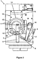
- An apparatus 101 for sorting gemstones, such as diamonds, from a batch of gemstones, will now be described with reference to Figures 3 to 7 .
- the gemstones to be sorted will typically comprise polished stones, both brilliant and fancy cut.
- a method of sorting gemstones from a batch will be described with reference to Figure 8 .
- the apparatus 101 comprises one or more measurement locations 110a, 110b, each comprising at least one measurement device configured to measure one or more properties of a gemstone, and a moveable surface 103 for supporting the gemstones thereon and for transporting the gemstones to the one or more measurement locations 110a, 110b.
- the apparatus 101 further comprises a separation device 107, 108 for separating the gemstones from one another as they are transported on the moveable surface 103 to the one or more measurement locations 110a, 110b.
- a location trigger such as a laser curtain 109.
- the position of that stone on the movable surface 103 is then known, and the subsequent location of the stone can be tracked by monitoring the movement of the surface 103. This enables measurements at the one or more measurement locations 110a, 110b to be correlated with the known locations of the gemstones on the moving surface 103.
- the moveable surface comprises a rotatable disc 103 having a substantially flat upper surface on which gemstones can be transported.
- the disc 103 is rotated by a motor (not shown here) at a rotational speed of approximately between 9 degrees/second and 13.5 degrees/second, depending on the size of the gemstones to be transported.
- the rotational speed of the disc 103 can be controlled via a controller, optionally including a screen 117.
- the surface of the rotatable disc 103 is manufactured to be flat, within a tolerance of 50 microns.
- the disc 103 is also hard black anodised so that it is hardwearing and to allow for measurements at the one or more measurements locations to be carried out in a substantially dark environment, as will be further discussed below.
- the disc 103 is also provided with a cover 104 which defines viewing ports through which gemstones being transported upon the disc 103 can be viewed.
- the apparatus 101 comprises a hopper 102 for receiving and delivering a batch of gemstones onto the surface of the rotatable disc 103, near the centre of the disc 103.
- the hopper 102 may be a hopper of the type described above with reference to Figures 1 and 2 .
- the hopper 102 comprises two counter-turning foam rollers (not shown here) which are used to control the flow of gemstones onto the rotatable disc 103.
- the speed of the rollers may be controlled via the controller 117 and can be varied according to the size and shape of gemstones being sorted.
- the hopper 102 has a minimum capacity of around 500 carats and is typically suitable for gemstones of between around 0.3 points to 30 points.
- the apparatus 101 further comprises an orientation device for orienting the gemstones as they are transported on a central portion of the rotatable disc 103, such that the gemstones are oriented into their most stable configuration prior to being separated from one another.
- the orientation device comprises an agitator 113 of the type described with reference to Figures 1 and 2 above, although without the vacuum wand.
- the agitator 113 comprises a pair of opposed parallel vertical walls 111 which form a substantially semi-circular channel 112, into which the gemstones are guided by the rotatable disc 103.
- the walls 111 are oscillated by an oscillator 115 such that a central portion 114 of the pair of walls 111 oscillates along the radius of the rotatable disc 103 i.e. generally transverse to the direction of travel of the gemstones. It will be understood that relative transverse movement of the pair of walls 111 may be minimal at the entry and exit portions of the semi-circular channel 112.
- the walls 111 are oscillated with sufficient magnitude and frequency that they collide with the gemstones that are present on the surface of the rotatable disc 103, knocking them into their most stable configuration i.e. their position of lowest potential energy.
- the most stable configuration will be table facet down.
- the impact level of the walls 111 is selected so that once a gemstone has landed on its most stable facet it will not be knocked over again and will remain in its most stable configuration.
- the impact level of the agitator 113 is carefully selected so that it is sufficient to knock a gemstone off its pavilion facet, for example, but not sufficient to knock a gemstone off its table facet.
- the length of the oscillating walls 111 is chosen so that all of the gemstones will have been orientated into their most stable configuration by the time they leave the agitator 113. Gemstones which have been oriented into their most stable configuration are easier to separate, measure and dispense as they handle more predictably.
- the apparatus 101 of this embodiment comprises a separation device 107, 108 for separating the gemstones from one another as they are transported on the rotatable disc 103 to the one or more measurement locations 110a, 110b.
- the separation device comprises a series of fixed cams 107 and a moveable cam 108.
- the gemstones come into contact with the cams 107 as the disc 103 rotates.
- the fixed cams 107 are inclined to the direction of travel of the horizontal surface so that the gemstones are pushed towards an outer region of the disc 103, which is moving faster than the central region of the disc 103. This thus increases the separation between the stones.
- Successive cam 107 surfaces may be inclined to the direction of travel of the horizontal surface of the rotatable disc 103 by successively smaller angles, and/or the cams 107 may include bent surfaces so as to optimise the rate at which the stones are moved laterally across the moving surface.
- each cam 107 pushes the gemstones successively further away from the central region of the rotatable disc 103, this naturally causes the gemstones to separate one from another as their average angular position with respect to the disc 103 is maintained while their distance from the centre of the rotatable disc 103 increases.
- the embodiment of Figures 3 to 7 further includes a moveable cam 108, with which the gemstones come into contact after they have passed the fixed cams 107.
- the angle of the moveable cam 108 surface can be adjusted in accordance with the size and shape of gemstone to be sorted.
- the moveable cam 108 is used to provide the final separation between the gemstones. In this way, once the gemstones have passed the moveable cam 108, a stream of separated gemstones is provided on the surface of the rotatable disc 103.
- Only one moveable cam 108 is provided in this example, it will be appreciated that further moveable cams may be provided as required. Additionally, the sequence of fixed and moveable cams may be varied.
- the apparatus 101 also comprises a location trigger 109.
- This is located at a sensor location on the disc 103 that the stones pass through after they have been separated, such that they need not make contact with any other item as they continue to travel on the disc 103.
- the location trigger comprises a sensor 109, for example a laser curtain, at the sensor location.
- the controller 117 is configured to receive a signal from the sensor every time a gemstone passes the sensor. The passage of that gemstone through the sensor is correlated with the angular position of the disc 103 at that moment, and the location of each gemstone can subsequently by tracked by knowledge of the angular position of the disc 103.
- the apparatus 101 further comprises one or more measurement locations 110a, 110b, each comprising at least one measurement device configured to measure one or more properties of the gemstones.
- Each measurement location 110a.110b comprises a measurement device or cell (not shown here). Separated gemstones pass through the measurement locations 110a, 110b one at a time, as the disc 103 rotates.
- Each measurement device measures a property of an individual gemstone as the gemstone moves past i.e. the rotatable disc 103 does not stop when the gemstones arrive at the measurement locations 110a, 110b and all measurements are performed upon moving gemstones.
- the disc 103 can rotate continuously and the correlation of the stones' position with the angular position of the disc 103 can be relied on. Measurements of the gemstones' properties are transmitted from the measurement devices to the controller 117. Further details of the measurements are detailed below.
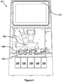
- the apparatus 101 further comprises a plurality of dispense locations, which in the example shown in Figures 3 , 4 and 5 comprise collection bins 105.
- collection bins 105 There are five collection bins 105 in this example, although it will be appreciated that the number of bins 105 may be reduced or increased as required.
- a dispensing mechanism 106 such as a push bar or a spiked foam wheel, operated via a solenoid 116 and configured to push a gemstone off the outer surface of the rotatable disc 103 and cause the gemstone to be dispensed into an associated collection bin 105.
- the five collection bins 105 illustrated in Figures 3 , 4 and 5 may be designated as follows:
- the controller 117 can accurately predict when the specific gemstone will pass the one or more measurement locations 110a, 110b. A measurement of one or more properties of the specific gemstone received by the controller 117 can therefore be correlated by the controller 117 with a location of the specific gemstone on the rotatable disc 103. The controller 117 can determine whether, for example, a specific gemstone is natural diamond, synthetic diamond or non-diamond, based upon the received measurements. When the specific gemstone arrives at a location adjacent the appropriate collection bin 105, the controller 117 activates the appropriate dispensing mechanism 106 to dispense the gemstone into the correct bin 105.
- a batch of gemstones is deposited into the hopper 102 and gemstones are individually delivered, via the foam rollers of the hopper 102, onto the surface of an inner region of the rotating disc 103.
- the gemstones are introduced into the semi-circular channel 112 of the agitator 113, where they are oriented table-down.
- the gemstones are brought by the rotating disc 103 into contact with the series of fixed cam surfaces 107 and the moveable cam surface 108, and are deflected towards an outer region of the rotatable disc 103, becoming separated from one another in the process.
- a separated stream of gemstones is transported by the rotatable disc 103 to the sensor location, where individual gemstones pass the sensor (laser curtain) 109 one at a time.
- the separated gemstones are then transported by the rotatable disc 103 through two successive measurement locations 110a, 110b, such that individual and different measurements are obtained of each gemstone at each location 110a, 110b. These measurements are transmitted to the controller 117 and associated with the gemstones to which they relate.
- the controller 117 tracks the accurate location of each measured gemstone, and activates the appropriate dispensing mechanism 106 to dispense the measured gemstone into the appropriate collection bin 105.
- the appropriate bin 105 is determined by the controller 117, based upon the measured properties of the gemstone.
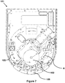
- a gemstone deposited by the hopper 102 onto an inner region of the rotating disc 103 follows a travelling path substantially as indicated by arrows A and eventually arrives at an outermost region of the disc 103, where it is dispensed into a collection bin 105.
- the orientation, separation, measurement and dispensing of gemstones from the batch may take place simultaneously.
- the first gemstones from the batch to be deposited onto the disc 103 may be being dispensed as subsequent gemstones from the same batch are being oriented, separated or measured.
- the entire batch of gemstones may be sorted without the need to stop the rotation of the disc 103, and hence the apparatus 101 of Figures 3 to 7 is capable of sorting a batch of gemstones into appropriate collection bins 105 at an approximate speed of at least 3,600 gemstones per hour.
- this gemstone may not be dispensed into a bin 105 but may instead remain upon the surface of the rotating disc 103.
- the gemstone may then be "recycled” by being deflected back to an appropriate inner region of the disc 103, so that it can pass the sensor and measurement locations 110a, 110b again.
- the apparatus 101 of Figures 3 to 7 comprises two measurement locations 110a, 110b, each comprising at least one measurement device configured to measure one or more properties of a gemstone. Separated gemstones are transported through the measurement locations 110a, 110b on the moving surface of the rotatable disc 103 one at a time. As discussed above, measurements at the measurements locations 110a, 110b are carried out in a substantially dark environment.
- the location of each gemstone is accurately known by the controller 117 and the controller 117 can therefore accurately determine when a specific gemstone will arrive at each of the two measurement locations110a, 110b. Measurements taken at each measurement location 110a, 110b can therefore be associated by the controller 117 with the specific gemstone to which they relate. Moreover, as the measurements taken do not require physical contact with the gemstones, the controller 117 can also accurately determine when a specific gemstone will arrive at each of the collection bins 105.
- the first measurement location 110a comprises a luminescence measurement cell.
- the luminescence measurement cell comprises a source of electromagnetic radiation at wavelengths of substantially 225 nanometres (nm) or less (i.e. an ultraviolet or UV lamp) for exciting a gemstone, and a light detection device or camera for capturing any visible light emitted by the gemstone upon excitation by the electromagnetic radiation.
- the operation of the UV lamp and the camera is synchronised by the controller 117, taking into account any offset value applicable to the camera.
- the lamp used in this example is a microsecond xenon spark lamp, such as a Perkin Elmer FX-4402, filtered to provide above diamond band-gap excitation at wavelengths of less than 225 nm.
- the camera in this example makes use of a complementary metal oxide semiconductor (CMOS) sensor, such as the Sony IMX174. Since the position of a specific gemstone upon the rotatable disc 103 is known by the controller 117, the excitation pulse and camera operation can be triggered to coincide with the arrival of a specific gemstone at the excitation and detection areas of the luminescence measurement cell 110a.
- CMOS complementary metal oxide semiconductor
- the camera can be configured with a delay by the controller system 117 so that the camera is able to only capture visible light during a time window which begins after the excitation pulse produced by the lamp has ended.
- the camera can capture phosphorescence as well as fluorescence. Since, in the vast majority of cases, the fluorescence decay is on time-scales shorter than that of the excitation source used here, it will be understood that fluorescence is a type of luminescence characterised as only being produced during ultraviolet excitation of the gemstone. Consequently, any fluorescence produced during excitation will decay very rapidly once the excitation is terminated. Phosphorescence on the other hand is a type of luminescence that remains once the excitation is removed, but subsequently decays away over a longer timescale.
- Phosphorescence can persist for some time after the excitation is terminated, or can decay within milliseconds of the end of the excitation pulse.
- the process of delaying capture of visible light until the excitation pulse has ended and any fluorescence has decayed ensures that the fluorescence is "gated out” and does not obscure any phosphorescence emitted after the end of the excitation pulse.
- the end of the time window for capturing visible light emitted by a gemstone may also be carefully selected to choose the decay time of the fluorescence and/or phosphorescence captured. In this way, the apparatus can capture visible light emissions which might otherwise be missed.
- the method may comprise irradiating the gemstone with multiple excitation pulses of electromagnetic radiation, and during and/or following each excitation pulse, detecting light emitted by the diamond in at least one time window having a predetermined time relationship relative to the excitation pulse so as to obtain luminescence data.
- the or each time window is chosen to include luminescence having a decay time characteristic of one or more of the markers.
- the luminescence data associated with all of the pulses may be combined and then analysed in order to establish the presence or absence of the one or more markers. These pulses and detections all take place as the stone passes through the measurement location 110a.
- One of the markers may be a blue fast phosphorescence marker comprising luminescence in a wavelength band peaking at about 450 nm and a decay time of less than about 80 milliseconds (ms). Testing for this may involve testing, in a time window opening at or after the end of the excitation pulse and ending about 80 milliseconds after the end of the associated excitation pulse, for a luminescence band peaking at about 450 nm.
- the presence of the blue fast phosphorescence marker may be an indicator that the diamond is a natural type IIa or la diamond.
- One of the markers may be a turquoise slow phosphorescence marker comprising luminescence having a wavelength peaking at about 480 nm and a decay time greater than 80 milliseconds. Testing for this may comprise testing, in a time window opening about 80 milliseconds after the end of the associated excitation pulse, for a luminescence band centred around 480 nm. The time window may close about 500 ms after the end of the associated excitation pulse, especially if multiple excitation pulses are used.
- the presence of the turquoise slow phosphorescence marker may be an indicator that the diamond is a type IIb diamond.
- One of the markers may be a green slow phosphorescence marker comprising luminescence having a wavelength between about 530 nm and about 550 nm and a decay time greater than 80 milliseconds. Testing for this marker may involve testing, in a time window opening about 80 milliseconds after the end of the associated excitation pulse, for a luminescence band between about 530 nm and about 550 nm. Again, the time window may optionally close about 500 ms after the end of the associated excitation pulse. The presence of the green slow phosphorescence marker may be an indicator that the diamond should be referred for further testing.
- One of the markers may be an "absence" marker where negligible luminescence is detected after the excitation pulse has ended.
- the presence of such a marker is an indicator that the diamond should be referred for further testing.
- One of the markers may be an orange long lived fluorescence marker comprising luminescence having a wavelength between about 535 nm and about 600 nm and a decay time less than 1 millisecond.
- the presence of the orange long lived fluorescence marker may be an indicator that the diamond should be referred for further testing.
- One of the markers may be a red phosphorescence marker comprising luminescence having a wavelength between about 575 nm and about 690 nm and a decay time greater than 1 millisecond.
- the presence of the red phosphorescence marker may be an indicator that the diamond should be referred for further testing.
- One of the markers may be a weak green fluorescence marker having a wavelength of about 510nm.
- Testing for the weak green fluorescence marker may comprise testing in a time window synchronised with an excitation pulse, since fluorescence is only produced during excitation of the gemstone and decays very rapidly once excitation is terminated. As previously discussed, the end of the time window will be carefully selected to coincide with the end of the pulse, so that any phosphorescence emitted after excitation of the gemstone has terminated, which might otherwise obscure the detection of weak fluorescence, will be "gated out”.
- the presence of the weak green fluorescence marker may be an indicator that the diamond should be referred for further testing.
- the measurement of fluorescence and/or phosphorescence and the presence of certain markers may enable a particular gemstone to be identified by the controller as natural type IIa, la or IIb diamond.
- the presence of a green slow phosphorescence marker or an "absence” marker does not permit an identification of the gemstone to be made, and in the absence of further information, any gemstone producing a green slow phosphorescence marker or an "absence” marker upon UV excitation would need to be "referred” for further testing using an alternate apparatus.
- the apparatus of Figures 3 to 7 comprises a second measurement location 110b, configured to measure one or more properties of a gemstone.
- the second measurement location 110b comprises a photoluminescence (PL) measurement cell.
- a gemstone passing through the PL measurement cell on the surface of the rotatable disc 103 undergoes laser excitation at around 450 nm with a 3mm diameter beam at an angle of 41 ° from the vertical.
- Detection of PL is carried out using a miniature spectrometer over a 3mm diameter measurement area using a single lens system at 0° from the vertical.
- the position of the gemstone on the rotatable disc 103 is known accurately by the controller 117 and is therefore used to trigger a PL measurement when the gemstone enters the PL measurement cell.
- the excitation laser, spectrometer and collection optics are optimised to allow a good quality (high signal to noise) PL spectrum to be acquired from moving gemstones within a time frame of approximately 150 milliseconds (the gemstone taking approximately 150 milliseconds to traverse the 3mm diameter PL measurement area).
- the controller 117 transmits to the controller 117 and analysed.
- a determination regarding the gemstone under test is produced and the gemstone is identified, based upon the presence of a Raman line and/or detection of Ni related PL features. The determination may be made based upon the results for the gemstone under test received from both the first and second measurement locations 110a, 110b, and therefore the determination may not be made until a gemstone has passed through both measurement locations 110a, 110b.
- the presence in the spectrum of a sharp, single Raman line centred at around 1332 cm -1 is an indicator that the gemstone under test contains diamond material and therefore is not a simulant i.e. that the gemstone is not composed of a substance other than diamond.
- the presence in the spectrum of Ni related PL features at around 787 nm in the absence of a stronger 793 nm feature. is an indicator that the gemstone under test is a natural diamond i.e. not a synthetic diamond. Therefore, the presence of both a sharp, single Raman line at around 1332 cm -1 and Ni related PL features at 787 nm but not 793 nm is an indicator that the gemstone under test is a natural diamond.
- the absence of a Raman line at around 1332 cm -1 is an indicator that the gemstone under test is non-diamond.
- the detection algorithm used by the controller 117 reaches a determination before the next gemstone in the separated stream of gemstones enters the PL measurement area.
- a gemstone which exhibited green slow phosphorescence during testing at the first measurement location 110a i.e. the luminescence measurement cell
- green phosphorescing natural diamond could either be incorrectly classified as synthetic diamond, or else might be "referred” for further testing by a further apparatus, resulting in a higher "referral" rate.
- the apparatus 101 of Figures 3 to 7 may therefore utilise a combination of different markers detected at the two measurement locations 110a, 110b to identify a gemstone, thus significantly reducing the number of gemstones in a batch which will require further testing by an alternate apparatus in order to be identified. Any gemstones which have still not been reliably identified after passing through both measurement locations 110a, 110b will typically be dispensed into the collection bin 105 designated "refer”. Such gemstones can then be subjected to further tests.
- Table 1 illustrates how combinations of different markers detected at the two measurement locations 110a, 110b of the apparatus 101 shown in Figures 3 to 7 may be used to identify a particular gemstone. The stone can then be dispensed into an appropriate collection bin 105.
- the contents of the second and third columns of Table 1 indicate whether certain of the phosphorescence markers discussed above are present or absent.
- phosphorescence is measured at the first measurement location 110a.
- "Blue” and “Not Blue” in the second column (“Phos 1”) indicates the presence and absence respectively of the blue fast phosphorescence marker comprising luminescence in a wavelength band peaking at about 450 nm and a decay time of less than about 80 ms after the end of the associated excitation pulse.
- the third column (“Phos 2”) indicates the presence and colour of slow phosphorescence having a decay time greater than about 80 ms.
- “Turquoise” in the third column indicates that this slow phosphorescence marker comprises luminescence having a wavelength peaking at about 480 nm and a decay time greater than 80 ms after the end of the associated excitation pulse, as discussed above.
- “Not Turquoise” in the third column indicates the absence of the turquoise slow phosphorescence marker. It will be appreciated that testing for these two markers comprises testing for phosphorescence in two separate time windows ( i.e. ⁇ 80 ms after the end of the excitation pulse and > 80 ms after the end of the excitation pulse).
- the contents of the fourth column of Table 1 indicate whether the weak green fluorescence marker discussed above, having a wavelength of about 510nm, is present (Weak Green) or absent (Not Weak Green).
- Testing for the weak green fluorescence marker may comprise testing in a time window synchronised with an excitation pulse i.e. testing for the marker during excitation of the gemstone. As discussed above, in this example, fluorescence is measured at the first measurement location 110a.
- the contents of the fifth column of Table 1 indicate whether specific Ni related PL features are present (a 787 nm feature in the absence of a stronger 793 nm feature) or not in the PL spectrum. As discussed above, in this example a PL spectrum is taken at the second measurement location 110b.
- a dash in any column means that any result is possible and that this measurement should be ignored.
- the gemstone under test can be identified as a simulant (i.e. non-diamond, such as cubic zirconia) regardless of which other markers may or may not be present.
- the majority of gemstones will be identified as natural diamond, simulant (i.e. non-diamond), or HPHT synthetic. Only in a few cases will a gemstone be referred for further testing.
- the gemstone under test will be dispensed to the "refer" collection bin.
- a method of sorting gemstones from a batch of gemstones comprises the steps of:
- Table 1 above illustrates testing for phosphorescence markers in two separate time windows, further time windows may be utilised to test for one or more further phosphorescence markers, as discussed above.
- markers identified above may be used as indicators of the type of gemstones even if the measurements are acquired using a different instrument.
Landscapes
- Health & Medical Sciences (AREA)
- Chemical & Material Sciences (AREA)
- Life Sciences & Earth Sciences (AREA)
- General Health & Medical Sciences (AREA)
- Analytical Chemistry (AREA)
- Biochemistry (AREA)
- General Physics & Mathematics (AREA)
- Immunology (AREA)
- Pathology (AREA)
- Physics & Mathematics (AREA)
- Food Science & Technology (AREA)
- Medicinal Chemistry (AREA)
- Engineering & Computer Science (AREA)
- Toxicology (AREA)
- Nuclear Medicine, Radiotherapy & Molecular Imaging (AREA)
- Investigating Materials By The Use Of Optical Means Adapted For Particular Applications (AREA)
- Investigating, Analyzing Materials By Fluorescence Or Luminescence (AREA)
- Sorting Of Articles (AREA)
- Polishing Bodies And Polishing Tools (AREA)
- Dry Shavers And Clippers (AREA)
- Crystals, And After-Treatments Of Crystals (AREA)
- Adornments (AREA)
Description
- The present invention relates to a method and an apparatus for sorting gemstones. In particular, although not exclusively, the invention relates to a method and an apparatus for sorting diamonds.
- Natural diamonds are stones from nature, consisting exclusively of diamond formed by geological processes over long periods of time. Synthetic diamonds are man-made stones manufactured by industrial processes, such as HPHT (high pressure high temperature) and CVD (chemical vapour deposition).
- Synthetic diamonds have a wide range of industrial applications, but currently form only a small percentage of the gemstone industry, and do not attract the high values associated with natural diamonds of similar colour and quality. Synthetic diamonds may be relatively easy to distinguish from natural diamonds when in an unpolished state, however, once polished and cut into a gemstone, identification that a stone is synthetic may be more difficult.
- Advanced screening instruments, such as the DiamondSure™ and DiamondView™, may be used to test whether a stone is natural or synthetic. Typically, such screening involves measuring the way in which light is absorbed by or emitted from a diamond. Before screening commences it is usually necessary for the stone being tested to be placed "table-down" in a precise location on the measurement surface or holder. In this context, the "table" is the largest central facet of the crown (the top half of the stone when mounted).
- In addition to screening larger, individual stones, it is also necessary to screen large numbers of smaller diamonds, including stones sometimes known as melee. Melee is a term of the trade that does not have a well-defined size range, but can be considered in practice to refer to stones smaller than about 0.2 carats (20 points), and usually (but not necessarily) larger than about 0.01 or 0.02 carats. Due to their small size, melee stones are typically sold in parcels or lots. Since one parcel may contain hundreds of stones, it is possible for synthetic diamonds and non-diamond material to be mixed in with natural stones.
- Screening of melee diamonds can potentially be extremely time consuming, since each stone must be tested individually and therefore placed in the correct orientation individually.
WO 2012/146913 discloses an apparatus for orientating gemstones, in which discrete gemstones are provided on a travelling path which has a pair of opposed oscillating walls. These walls urge the gemstones into their most stable orientation (i.e. table-down) as they progress along the path. Once in this orientation, individual stones may be lifted from the travelling path by a vacuum wand and transported to a test station. -
Figure 1 is a view of the apparatus 1 described inWO 2012/146913 for orientating gemstones. The melee stones are poured into ahopper 2 and pass through a pair ofrollers 6. The speed of therollers 6 is configured to separate out the stones so they pass through one at a time. The stones are then directed onto a rotatingdisc 10, as shown inFigure 2 . Thedisc 10 rotates clockwise and provides a circular travelling path, passing the stones through anagitator 13. Theagitator 13 comprises a pair of opposed parallelvertical walls 11 which form asemi-circular channel 12. Thewalls 11 are connected to anoscillator 15 which oscillates the walls with sufficient magnitude and frequency that they collide with the stones on the travelling path. The centre of the pair ofwalls 14 oscillates along the radius of the rotatingdisc 10. - The impact level of the
walls 11 is chosen such that it is enough to knock a stone off its pavilion facet, but not to knock a stone off its most stable table facet. Eventually, the stones land table-down and are aligned by the time they reach ahandling area 7. Anorientation checking device 9 checks that each stone is table-down, by recording a side view silhouette image of the stone with acamera 16. If the stone is found to be correctly orientated, it is collected by the handler, comprising a swingingarm 3 and a vacuum wand 4, and transported to asynthetic detection device 17. If the stone is found to be incorrectly orientated, it will be transported back to the oscillatingchannel 12 to be re-orientated. This process continues until all stones in the melee have been orientated, tested and dispensed into anappropriate collection bin 5 viachutes 8. While the apparatus ofFigure 1 speeds up the orientation and testing process, it is still necessary to halt the rotation of thedisc 10 each time an oriented stone is ready to be picked up by the vacuum wand 4. Moreover, conventional testing devices and methods often fail to conclusively identify a stone as natural or synthetic. Where a conclusive identification is not possible, stones must be "referred" for further testing. Further testing typically requires the use of more complex methods such as photoluminescence or Raman spectroscopy and/or one or more different devices. For very small gemstones, further testing may not be economically viable.WO 2015/024979 describes one system which attempts to address this problem by distinguishing between diamond and non-diamond material on a rotating glass disc using Raman spectroscopy and subsequently carrying out measurements of UV transmission intensity on stones passed as containing diamond material.WO 2014/067932 describes an apparatus for dropping stones onto a rotatable disc and transporting them to a measurement location, according to the preamble of independent claim 1. - In accordance with the present invention there is provided an apparatus for sorting gemstones from a batch of gemstones according to independent claim 1. The apparatus comprises one or more measurement locations, each comprising at least one measurement device configured to measure one or more properties of a gemstone. A continuously moveable surface supports the gemstones thereon and transports the gemstones to the one or more measurement locations. A separation device separates the gemstones from one another as they are transported on the moveable surface to the one or more measurement locations. A location trigger at a sensor location comprises a sensor for identifying when the gemstone passes through the sensor location. A controller receives a signal from the location trigger, records the position of the moveable surface when the signal is received, and tracks the subsequent location of the gemstone by monitoring the movement of the moveable surface such that a measurement of the one or more properties of each gemstone can be correlated with a location of the respective gemstone on the moveable surface. Specific markers in the luminescence properties of the gemstone may be used to identify properties of the stone.
- Also in accordance with the present invention there is provided a method of sorting gemstones from a batch of gemstones according to
independent claim 12. The method comprising the steps of:
transporting gemstones to one or more measurement locations on a continuously moveable surface; separating the gemstones from one another as they are transported on the moveable surface to the one or more measurement locations; after the gemstones have been separated, identifying each moment that a gemstone passes a sensor location, associating that gemstone with the position of the moveable surface at that moment, and tracking the subsequent location of the gemstone by monitoring the movement of the moveable surface; measuring one or more properties of a gemstone at the one or more measurement locations; and correlating each measurement of the one or more properties of each gemstone with the location of the respective gemstone on the moveable surface. - The one or more properties may comprises one or more specific markers in the luminescence properties of the gemstone. These markers may include the wavelength and decay time of the luminescence. Particular combinations of markers may provide indications as to whether or not the stone contains diamond material and, if so, whether it is natural or synthetic or requires further testing.
- Further aspects and preferred features are set out in the respective dependent claims.
-
-
Figure 1 is a perspective view of a known apparatus for orientating gemstones; -
Figure 2 is a plan view of the apparatus ofFigure 1 , with components removed for clarity; -
Figure 3 is a perspective view of an apparatus for orientating gemstones according to the present invention; -
Figure 4 is a front view of the apparatus ofFigure 3 ; -
Figure 5 is a top down view of the apparatus ofFigure 3 ; -
Figure 6 is a further top down view of the apparatus ofFigure 3 , illustrating an orientation device; -
Figure 7 is a top down view of the apparatus ofFigure 3 , illustrating a direction of travel of a batch of gemstones; and -
Figure 8 is a flow chart illustrating a method of sorting gemstones from a batch of gemstones. - An
apparatus 101 for sorting gemstones, such as diamonds, from a batch of gemstones, will now be described with reference toFigures 3 to 7 . The gemstones to be sorted will typically comprise polished stones, both brilliant and fancy cut. A method of sorting gemstones from a batch will be described with reference toFigure 8 . - The
apparatus 101 comprises one ormore measurement locations moveable surface 103 for supporting the gemstones thereon and for transporting the gemstones to the one ormore measurement locations apparatus 101 further comprises aseparation device moveable surface 103 to the one ormore measurement locations laser curtain 109. The position of that stone on themovable surface 103 is then known, and the subsequent location of the stone can be tracked by monitoring the movement of thesurface 103. This enables measurements at the one ormore measurement locations surface 103. - In the embodiment of
Figures 3 to 7 , the moveable surface comprises arotatable disc 103 having a substantially flat upper surface on which gemstones can be transported. Thedisc 103 is rotated by a motor (not shown here) at a rotational speed of approximately between 9 degrees/second and 13.5 degrees/second, depending on the size of the gemstones to be transported. The rotational speed of thedisc 103 can be controlled via a controller, optionally including ascreen 117. - In the illustrated example of
Figures 3 to 7 , the surface of therotatable disc 103 is manufactured to be flat, within a tolerance of 50 microns. Thedisc 103 is also hard black anodised so that it is hardwearing and to allow for measurements at the one or more measurements locations to be carried out in a substantially dark environment, as will be further discussed below. To this end, thedisc 103 is also provided with acover 104 which defines viewing ports through which gemstones being transported upon thedisc 103 can be viewed. - As best shown in
Figure 3 , theapparatus 101 comprises ahopper 102 for receiving and delivering a batch of gemstones onto the surface of therotatable disc 103, near the centre of thedisc 103. Thehopper 102 may be a hopper of the type described above with reference toFigures 1 and2 . Thehopper 102 comprises two counter-turning foam rollers (not shown here) which are used to control the flow of gemstones onto therotatable disc 103. The speed of the rollers may be controlled via thecontroller 117 and can be varied according to the size and shape of gemstones being sorted. In this example, thehopper 102 has a minimum capacity of around 500 carats and is typically suitable for gemstones of between around 0.3 points to 30 points. - In the embodiment of
Figures 3 to 7 and as best shown inFigure 5 , theapparatus 101 further comprises an orientation device for orienting the gemstones as they are transported on a central portion of therotatable disc 103, such that the gemstones are oriented into their most stable configuration prior to being separated from one another. In this example, the orientation device comprises anagitator 113 of the type described with reference toFigures 1 and2 above, although without the vacuum wand. Theagitator 113 comprises a pair of opposed parallelvertical walls 111 which form a substantiallysemi-circular channel 112, into which the gemstones are guided by therotatable disc 103. - The
walls 111 are oscillated by anoscillator 115 such that acentral portion 114 of the pair ofwalls 111 oscillates along the radius of therotatable disc 103 i.e. generally transverse to the direction of travel of the gemstones. It will be understood that relative transverse movement of the pair ofwalls 111 may be minimal at the entry and exit portions of thesemi-circular channel 112. - The
walls 111 are oscillated with sufficient magnitude and frequency that they collide with the gemstones that are present on the surface of therotatable disc 103, knocking them into their most stable configuration i.e. their position of lowest potential energy. For the vast majority of cut gemstones, the most stable configuration will be table facet down. The impact level of thewalls 111 is selected so that once a gemstone has landed on its most stable facet it will not be knocked over again and will remain in its most stable configuration. In other words, the impact level of theagitator 113 is carefully selected so that it is sufficient to knock a gemstone off its pavilion facet, for example, but not sufficient to knock a gemstone off its table facet. - The length of the
oscillating walls 111 is chosen so that all of the gemstones will have been orientated into their most stable configuration by the time they leave theagitator 113. Gemstones which have been oriented into their most stable configuration are easier to separate, measure and dispense as they handle more predictably. - The
apparatus 101 of this embodiment comprises aseparation device rotatable disc 103 to the one ormore measurement locations Figures 3 to 7 , the separation device comprises a series of fixedcams 107 and amoveable cam 108. The gemstones come into contact with thecams 107 as thedisc 103 rotates. The fixedcams 107 are inclined to the direction of travel of the horizontal surface so that the gemstones are pushed towards an outer region of thedisc 103, which is moving faster than the central region of thedisc 103. This thus increases the separation between the stones.Successive cam 107 surfaces may be inclined to the direction of travel of the horizontal surface of therotatable disc 103 by successively smaller angles, and/or thecams 107 may include bent surfaces so as to optimise the rate at which the stones are moved laterally across the moving surface. In this example, there are three fixedcams 107, but it will be appreciated that fewer oradditional cams 107 may be employed, as required. - Since each
cam 107 pushes the gemstones successively further away from the central region of therotatable disc 103, this naturally causes the gemstones to separate one from another as their average angular position with respect to thedisc 103 is maintained while their distance from the centre of therotatable disc 103 increases. - The embodiment of
Figures 3 to 7 further includes amoveable cam 108, with which the gemstones come into contact after they have passed the fixedcams 107. The angle of themoveable cam 108 surface can be adjusted in accordance with the size and shape of gemstone to be sorted. Themoveable cam 108 is used to provide the final separation between the gemstones. In this way, once the gemstones have passed themoveable cam 108, a stream of separated gemstones is provided on the surface of therotatable disc 103. Although only onemoveable cam 108 is provided in this example, it will be appreciated that further moveable cams may be provided as required. Additionally, the sequence of fixed and moveable cams may be varied. - As shown in
Figure 5 , theapparatus 101 also comprises alocation trigger 109. This is located at a sensor location on thedisc 103 that the stones pass through after they have been separated, such that they need not make contact with any other item as they continue to travel on thedisc 103. In this embodiment, the location trigger comprises asensor 109, for example a laser curtain, at the sensor location. Thecontroller 117 is configured to receive a signal from the sensor every time a gemstone passes the sensor. The passage of that gemstone through the sensor is correlated with the angular position of thedisc 103 at that moment, and the location of each gemstone can subsequently by tracked by knowledge of the angular position of thedisc 103. - The
apparatus 101 further comprises one ormore measurement locations Figures 3 to 7 , there are twomeasurement locations measurement locations disc 103 rotates. Each measurement device measures a property of an individual gemstone as the gemstone moves past i.e. therotatable disc 103 does not stop when the gemstones arrive at themeasurement locations disc 103 can rotate continuously and the correlation of the stones' position with the angular position of thedisc 103 can be relied on. Measurements of the gemstones' properties are transmitted from the measurement devices to thecontroller 117. Further details of the measurements are detailed below. - The
apparatus 101 further comprises a plurality of dispense locations, which in the example shown inFigures 3 ,4 and5 comprisecollection bins 105. There are fivecollection bins 105 in this example, although it will be appreciated that the number ofbins 105 may be reduced or increased as required. Associated with eachcollection bin 105 is adispensing mechanism 106, such as a push bar or a spiked foam wheel, operated via asolenoid 116 and configured to push a gemstone off the outer surface of therotatable disc 103 and cause the gemstone to be dispensed into an associatedcollection bin 105. The fivecollection bins 105 illustrated inFigures 3 ,4 and5 may be designated as follows: - 1. non-diamond (for gemstones which consist of simulants e.g. cubic zirconia)
- 2. synthetic (for synthetic diamonds, such as those grown by CVD or HPHT)
- 3. pass (for natural diamonds)
- 4. refer (for gemstones whose properties have not been conclusively determined)
- 5. purge (for use when it is desired to quickly empty the apparatus of gemstones).
- It will be appreciated that the above sequence of
collection bins 105 is provided by way of example only and other designations and sequences may be envisaged. - Since the time at which a specific gemstone passes the sensor location and the rotational speed of the
disc 103 are known, thecontroller 117 can accurately predict when the specific gemstone will pass the one ormore measurement locations controller 117 can therefore be correlated by thecontroller 117 with a location of the specific gemstone on therotatable disc 103. Thecontroller 117 can determine whether, for example, a specific gemstone is natural diamond, synthetic diamond or non-diamond, based upon the received measurements. When the specific gemstone arrives at a location adjacent theappropriate collection bin 105, thecontroller 117 activates theappropriate dispensing mechanism 106 to dispense the gemstone into thecorrect bin 105. - The
apparatus 101 ofFigures 3 to 7 will now be described in use. A batch of gemstones is deposited into thehopper 102 and gemstones are individually delivered, via the foam rollers of thehopper 102, onto the surface of an inner region of therotating disc 103. As thedisc 103 rotates, the gemstones are introduced into thesemi-circular channel 112 of theagitator 113, where they are oriented table-down. Upon leaving theagitator 113, the gemstones are brought by therotating disc 103 into contact with the series of fixed cam surfaces 107 and themoveable cam surface 108, and are deflected towards an outer region of therotatable disc 103, becoming separated from one another in the process. Thus, a separated stream of gemstones is transported by therotatable disc 103 to the sensor location, where individual gemstones pass the sensor (laser curtain) 109 one at a time. - The separated gemstones are then transported by the
rotatable disc 103 through twosuccessive measurement locations location controller 117 and associated with the gemstones to which they relate. Thecontroller 117 tracks the accurate location of each measured gemstone, and activates theappropriate dispensing mechanism 106 to dispense the measured gemstone into theappropriate collection bin 105. Theappropriate bin 105 is determined by thecontroller 117, based upon the measured properties of the gemstone. - Hence, as illustrated in
Figure 7 , a gemstone deposited by thehopper 102 onto an inner region of therotating disc 103 follows a travelling path substantially as indicated by arrows A and eventually arrives at an outermost region of thedisc 103, where it is dispensed into acollection bin 105. It will be appreciated that, since the batch of gemstones is deposited onto therotatable disc 103 gradually, the orientation, separation, measurement and dispensing of gemstones from the batch may take place simultaneously. In other words, the first gemstones from the batch to be deposited onto thedisc 103 may be being dispensed as subsequent gemstones from the same batch are being oriented, separated or measured. In this way, the entire batch of gemstones may be sorted without the need to stop the rotation of thedisc 103, and hence theapparatus 101 ofFigures 3 to 7 is capable of sorting a batch of gemstones intoappropriate collection bins 105 at an approximate speed of at least 3,600 gemstones per hour. - It will be noted that, in a situation where a gemstone is determined by the
controller 117 to have been incorrectly measured, or not measured at all, this gemstone may not be dispensed into abin 105 but may instead remain upon the surface of therotating disc 103. The gemstone may then be "recycled" by being deflected back to an appropriate inner region of thedisc 103, so that it can pass the sensor andmeasurement locations - As described above, the
apparatus 101 ofFigures 3 to 7 comprises twomeasurement locations measurement locations rotatable disc 103 one at a time. As discussed above, measurements at themeasurements locations - Since the gemstones on the
disc 103 do not come into contact with any other part of the apparatus after passing the sensor location, the location of each gemstone is accurately known by thecontroller 117 and thecontroller 117 can therefore accurately determine when a specific gemstone will arrive at each of the two measurement locations110a, 110b. Measurements taken at eachmeasurement location controller 117 with the specific gemstone to which they relate. Moreover, as the measurements taken do not require physical contact with the gemstones, thecontroller 117 can also accurately determine when a specific gemstone will arrive at each of thecollection bins 105. - In this embodiment, the
first measurement location 110a comprises a luminescence measurement cell. The luminescence measurement cell comprises a source of electromagnetic radiation at wavelengths of substantially 225 nanometres (nm) or less (i.e. an ultraviolet or UV lamp) for exciting a gemstone, and a light detection device or camera for capturing any visible light emitted by the gemstone upon excitation by the electromagnetic radiation. - The operation of the UV lamp and the camera is synchronised by the
controller 117, taking into account any offset value applicable to the camera. The lamp used in this example is a microsecond xenon spark lamp, such as a Perkin Elmer FX-4402, filtered to provide above diamond band-gap excitation at wavelengths of less than 225 nm. The camera in this example makes use of a complementary metal oxide semiconductor (CMOS) sensor, such as the Sony IMX174. Since the position of a specific gemstone upon therotatable disc 103 is known by thecontroller 117, the excitation pulse and camera operation can be triggered to coincide with the arrival of a specific gemstone at the excitation and detection areas of theluminescence measurement cell 110a. - The camera can be configured with a delay by the
controller system 117 so that the camera is able to only capture visible light during a time window which begins after the excitation pulse produced by the lamp has ended. Thus, the camera can capture phosphorescence as well as fluorescence. Since, in the vast majority of cases, the fluorescence decay is on time-scales shorter than that of the excitation source used here, it will be understood that fluorescence is a type of luminescence characterised as only being produced during ultraviolet excitation of the gemstone. Consequently, any fluorescence produced during excitation will decay very rapidly once the excitation is terminated. Phosphorescence on the other hand is a type of luminescence that remains once the excitation is removed, but subsequently decays away over a longer timescale. Phosphorescence can persist for some time after the excitation is terminated, or can decay within milliseconds of the end of the excitation pulse. The process of delaying capture of visible light until the excitation pulse has ended and any fluorescence has decayed ensures that the fluorescence is "gated out" and does not obscure any phosphorescence emitted after the end of the excitation pulse. The end of the time window for capturing visible light emitted by a gemstone may also be carefully selected to choose the decay time of the fluorescence and/or phosphorescence captured. In this way, the apparatus can capture visible light emissions which might otherwise be missed. - A method of determining whether a gemstone is natural or synthetic by observing certain specific markers in the luminescence properties of the gemstone will now be described. The method may comprise irradiating the gemstone with multiple excitation pulses of electromagnetic radiation, and during and/or following each excitation pulse, detecting light emitted by the diamond in at least one time window having a predetermined time relationship relative to the excitation pulse so as to obtain luminescence data. The or each time window is chosen to include luminescence having a decay time characteristic of one or more of the markers. The luminescence data associated with all of the pulses may be combined and then analysed in order to establish the presence or absence of the one or more markers. These pulses and detections all take place as the stone passes through the
measurement location 110a. - One of the markers may be a blue fast phosphorescence marker comprising luminescence in a wavelength band peaking at about 450 nm and a decay time of less than about 80 milliseconds (ms). Testing for this may involve testing, in a time window opening at or after the end of the excitation pulse and ending about 80 milliseconds after the end of the associated excitation pulse, for a luminescence band peaking at about 450 nm. The presence of the blue fast phosphorescence marker may be an indicator that the diamond is a natural type IIa or la diamond.
- One of the markers may be a turquoise slow phosphorescence marker comprising luminescence having a wavelength peaking at about 480 nm and a decay time greater than 80 milliseconds. Testing for this may comprise testing, in a time window opening about 80 milliseconds after the end of the associated excitation pulse, for a luminescence band centred around 480 nm. The time window may close about 500 ms after the end of the associated excitation pulse, especially if multiple excitation pulses are used. The presence of the turquoise slow phosphorescence marker may be an indicator that the diamond is a type IIb diamond.
- One of the markers may be a green slow phosphorescence marker comprising luminescence having a wavelength between about 530 nm and about 550 nm and a decay time greater than 80 milliseconds. Testing for this marker may involve testing, in a time window opening about 80 milliseconds after the end of the associated excitation pulse, for a luminescence band between about 530 nm and about 550 nm. Again, the time window may optionally close about 500 ms after the end of the associated excitation pulse. The presence of the green slow phosphorescence marker may be an indicator that the diamond should be referred for further testing.
- One of the markers may be an "absence" marker where negligible luminescence is detected after the excitation pulse has ended. The presence of such a marker is an indicator that the diamond should be referred for further testing.
- One of the markers may be an orange long lived fluorescence marker comprising luminescence having a wavelength between about 535 nm and about 600 nm and a decay time less than 1 millisecond. The presence of the orange long lived fluorescence marker may be an indicator that the diamond should be referred for further testing.
- One of the markers may be a red phosphorescence marker comprising luminescence having a wavelength between about 575 nm and about 690 nm and a decay time greater than 1 millisecond. The presence of the red phosphorescence marker may be an indicator that the diamond should be referred for further testing.
- One of the markers may be a weak green fluorescence marker having a wavelength of about 510nm. Testing for the weak green fluorescence marker may comprise testing in a time window synchronised with an excitation pulse, since fluorescence is only produced during excitation of the gemstone and decays very rapidly once excitation is terminated. As previously discussed, the end of the time window will be carefully selected to coincide with the end of the pulse, so that any phosphorescence emitted after excitation of the gemstone has terminated, which might otherwise obscure the detection of weak fluorescence, will be "gated out". The presence of the weak green fluorescence marker may be an indicator that the diamond should be referred for further testing.
- It will be appreciated from the above that the measurement of fluorescence and/or phosphorescence and the presence of certain markers may enable a particular gemstone to be identified by the controller as natural type IIa, la or IIb diamond. However, the presence of a green slow phosphorescence marker or an "absence" marker, for example, does not permit an identification of the gemstone to be made, and in the absence of further information, any gemstone producing a green slow phosphorescence marker or an "absence" marker upon UV excitation would need to be "referred" for further testing using an alternate apparatus.
- Advantageously, the apparatus of
Figures 3 to 7 comprises asecond measurement location 110b, configured to measure one or more properties of a gemstone. In this embodiment, thesecond measurement location 110b comprises a photoluminescence (PL) measurement cell. - A gemstone passing through the PL measurement cell on the surface of the
rotatable disc 103 undergoes laser excitation at around 450 nm with a 3mm diameter beam at an angle of 41 ° from the vertical. Detection of PL is carried out using a miniature spectrometer over a 3mm diameter measurement area using a single lens system at 0° from the vertical. The position of the gemstone on therotatable disc 103 is known accurately by thecontroller 117 and is therefore used to trigger a PL measurement when the gemstone enters the PL measurement cell. The excitation laser, spectrometer and collection optics are optimised to allow a good quality (high signal to noise) PL spectrum to be acquired from moving gemstones within a time frame of approximately 150 milliseconds (the gemstone taking approximately 150 milliseconds to traverse the 3mm diameter PL measurement area). - Once the PL spectrum has been acquired it is transmitted to the
controller 117 and analysed. A determination regarding the gemstone under test is produced and the gemstone is identified, based upon the presence of a Raman line and/or detection of Ni related PL features. The determination may be made based upon the results for the gemstone under test received from both the first andsecond measurement locations measurement locations - The presence in the spectrum of a sharp, single Raman line centred at around 1332 cm-1 is an indicator that the gemstone under test contains diamond material and therefore is not a simulant i.e. that the gemstone is not composed of a substance other than diamond. The presence in the spectrum of Ni related PL features at around 787 nm in the absence of a stronger 793 nm feature.is an indicator that the gemstone under test is a natural diamond i.e. not a synthetic diamond. Therefore, the presence of both a sharp, single Raman line at around 1332 cm-1 and Ni related PL features at 787 nm but not 793 nm is an indicator that the gemstone under test is a natural diamond. In contrast, the absence of a Raman line at around 1332 cm-1 is an indicator that the gemstone under test is non-diamond. The detection algorithm used by the
controller 117 reaches a determination before the next gemstone in the separated stream of gemstones enters the PL measurement area. - Therefore, a gemstone which exhibited green slow phosphorescence during testing at the
first measurement location 110a, i.e. the luminescence measurement cell, can be identified as either natural diamond or synthetic diamond following testing at thesecond measurement location 110b, i.e. the PL measurement cell. As discussed above, without this capability, green phosphorescing natural diamond could either be incorrectly classified as synthetic diamond, or else might be "referred" for further testing by a further apparatus, resulting in a higher "referral" rate. - The
apparatus 101 ofFigures 3 to 7 may therefore utilise a combination of different markers detected at the twomeasurement locations measurement locations collection bin 105 designated "refer". Such gemstones can then be subjected to further tests. - Table 1 illustrates how combinations of different markers detected at the two
measurement locations apparatus 101 shown inFigures 3 to 7 may be used to identify a particular gemstone. The stone can then be dispensed into anappropriate collection bin 105. - Beginning from the left, the contents of the first column of Table 1 (Raman) indicate whether a sharp, single Raman line centred at around 1332 cm-1 is present ("1332") or not present ("Not 1332") in the PL spectrum. As discussed above, in this example a PL spectrum is taken at the
second measurement location 110b. - The contents of the second and third columns of Table 1 (Phos 1, Phos 2) indicate whether certain of the phosphorescence markers discussed above are present or absent. As discussed above, in this example, phosphorescence is measured at the
first measurement location 110a. "Blue" and "Not Blue" in the second column ("Phos 1") indicates the presence and absence respectively of the blue fast phosphorescence marker comprising luminescence in a wavelength band peaking at about 450 nm and a decay time of less than about 80 ms after the end of the associated excitation pulse. The third column ("Phos 2") indicates the presence and colour of slow phosphorescence having a decay time greater than about 80 ms. "Turquoise" in the third column indicates that this slow phosphorescence marker comprises luminescence having a wavelength peaking at about 480 nm and a decay time greater than 80 ms after the end of the associated excitation pulse, as discussed above. "Not Turquoise" in the third column indicates the absence of the turquoise slow phosphorescence marker. It will be appreciated that testing for these two markers comprises testing for phosphorescence in two separate time windows (i.e. < 80 ms after the end of the excitation pulse and > 80 ms after the end of the excitation pulse). - The contents of the fourth column of Table 1 (Fluorescence) indicate whether the weak green fluorescence marker discussed above, having a wavelength of about 510nm, is present (Weak Green) or absent (Not Weak Green). Testing for the weak green fluorescence marker may comprise testing in a time window synchronised with an excitation pulse i.e. testing for the marker during excitation of the gemstone. As discussed above, in this example, fluorescence is measured at the
first measurement location 110a. - The contents of the fifth column of Table 1 (PL) indicate whether specific Ni related PL features are present (a 787 nm feature in the absence of a stronger 793 nm feature) or not in the PL spectrum. As discussed above, in this example a PL spectrum is taken at the
second measurement location 110b. - A dash in any column means that any result is possible and that this measurement should be ignored. For example, as indicated in Row 1 of Table 1, where no sharp, single Raman line centred at around 1332 cm-1 is present in the PL spectrum (Not 1332), the gemstone under test can be identified as a simulant (i.e. non-diamond, such as cubic zirconia) regardless of which other markers may or may not be present.
Table 1: Raman Phos 1 Phos 2Fluorescence PL Identification 1 Not 1332 - - - - Simulant 2 1332 Blue - - - Natural 3 1332 Not Blue Blue - - Natural 4 1332 Not Blue Turquoise Weak Green - HPHT Synthetic 5 1332 Not Blue Turquoise Not Weak Green 787 nm Natural 6 1332 Not Blue Turquoise Not Weak Green No 787 nm Refer 7 1332 Not Blue Not Turquoise - 787 nm Natural 8 1332 Not Blue Not Turquoise - No 787 nm Refer - As can be seen from Table 1, the majority of gemstones will be identified as natural diamond, simulant (i.e. non-diamond), or HPHT synthetic. Only in a few cases will a gemstone be referred for further testing. For example, as shown in
Row 6 of Table 1, in the case where the Raman line at around 1332 cm-1 in the PL spectrum and the turquoise slow phosphorescence marker are both present, but the blue fast phosphorescence marker, the weak green fluorescence marker and the Ni related PL features at 787 nm in the PL spectrum are all absent, the gemstone under test will be dispensed to the "refer" collection bin. - With reference to
Figure 8 , a method of sorting gemstones from a batch of gemstones comprises the steps of: - Step 1: transporting gemstones to one or more measurement locations on a continuously moveable surface;
- Step 2: separating the gemstones from one another as they are transported on the moveable surface to the one or more measurement locations;
- Step 3: after the gemstones have been separated, identifying each moment that a gemstone passes a sensor location, associating that gemstone with the position of the moveable surface at that moment, and tracking the subsequent location of the gemstone by monitoring the movement of the moveable surface;
- Step 4: measuring one or more properties of a gemstone at the one or more measurement locations; and
- Step 5: correlating each measurement of the one or more properties of each gemstone with the location of the respective gemstone on the moveable surface.
- It will be appreciated by the person skilled in the art that various modifications may be made to the above described embodiment, without departing from the scope of the present invention. For example, although the embodiment described above comprises two
measurement locations - Further, although Table 1 above illustrates testing for phosphorescence markers in two separate time windows, further time windows may be utilised to test for one or more further phosphorescence markers, as discussed above.
- Furthermore, it will be appreciated that the markers identified above may be used as indicators of the type of gemstones even if the measurements are acquired using a different instrument.
Claims (16)
- An apparatus for sorting gemstones from a batch of gemstones, the apparatus comprising:one or more measurement locations (110a,110b), each comprising at least one measurement device configured to measure one or more properties of a gemstone;a continuously moveable surface (103) for supporting the gemstones thereon and for transporting the gemstones to the one or more measurement locations;a separation device (107,108) for separating the gemstones from one another as they are transported on the moveable surface to the one or more measurement locations;a location trigger (109) comprising a sensor at a sensor location for identifying when the gemstone passes through the sensor location; anda controller configured to receive a signal from the location trigger and record the position of the moveable surface when the signal is received;characterised in that the controller is further configured to track the subsequent location of the gemstone by monitoring the movement of the moveable surface such that a measurement of the one or more properties of each gemstone can be correlated with a location of the respective gemstone on the moveable surface.
- An apparatus as claimed in claim 1, further comprising an orientation device (113) for orienting the gemstones as they are transported to the separation device (107,108), such that the gemstones are oriented into their most stable configuration prior to being separated from one another, wherein optionally the orientation device comprises a pair of opposed parallel vertical walls (111) which form a substantially semi-circular channel (112), the pair of walls being oscillated by an oscillator (115) such that a central portion of the pair of walls oscillates in a direction generally transverse to a direction of travel of the gemstones.
- An apparatus as claimed in claim 1 or 2, wherein each measurement device is configured to measure the one or more properties of the gemstone as it moves through the measurement location on the moveable surface.
- An apparatus as claimed in any one of the preceding claims, wherein the separation device comprises a series of cam surfaces located above and closely proximate to the moveable surface, each cam surface being inclined to a direction of travel of the moveable surface, so that the gemstones are pushed successively further from their initial line of travel by successive cams in the series.
- An apparatus as claimed in any preceding claims, wherein the moveable surface comprises a rotatable disc.
- An apparatus as claimed in claim 5, wherein gemstones are delivered onto an inner region of the rotatable disc and are subsequently dispensed into a collection bin (105) located adjacent an outermost region of the rotatable disc, according to their measured properties.
- An apparatus as claimed in any preceding claim, wherein the moveable surface has a dark surface.
- An apparatus as claimed in any preceding claim, further comprising a plurality of dispensing locations, each location comprising a collection bin (105) and an associated dispensing mechanism (106), and wherein the associated dispensing mechanism comprises one of a push bar and a spiked foam wheel.
- An apparatus as claimed in any preceding claim, wherein a first measurement location (110a) of the one or more measurement locations comprises a first measurement device configured to measure luminescence emitted by the gemstones following excitation by a UV source, and optionally measure the wavelength of the luminescence;wherein optionally the luminescence is measured in a plurality of different time windows following a pulse of excitation by the UV source;and wherein optionally the different time windows include one or more of:a window synchronised with the start and end of the pulse so as to measure fluorescence;a window which opens at the end of the pulse and closes after about 80 ms to measure fast phosphorescence; anda window which opens about 80 ms after the end of the pulse and closes before a subsequent pulse to measure slow phosphorescence.
- An apparatus as claimed in any preceding claim, wherein a second measurement location (110b) comprises a measurement device configured to measure photoluminescence emitted by the gemstones following laser excitation.
- An apparatus as claimed in any preceding claim, further comprising a hopper (102) configured to receive and deliver a batch of gemstones onto the moveable surface (103).
- A method of sorting gemstones from a batch of gemstones, the method comprising the steps of:transporting gemstones to one or more measurement locations (110a,110b) on a continuously moveable surface (103);separating the gemstones from one another as they are transported on the moveable surface to the one or more measurement locations;after the gemstones have been separated, identifying each moment that a gemstone passes a sensor location (109), associating that gemstone with the position of the moveable surface at that moment, and tracking the subsequent location of the gemstone by monitoring the movement of the moveable surface;measuring one or more properties of a gemstone at the one or more measurement locations; andcorrelating each measurement of the one or more properties of each gemstone with the location of the respective gemstone on the moveable surface.
- A method as claimed in claim 12, wherein the one or more properties comprises one or more specific markers in the luminescence and/or photoluminescence properties of the gemstone;wherein optionally one of the one or more specific markers is a blue fast phosphorescence marker comprising luminescence in a wavelength band peaking at about 450 nm and a decay time of less than about 80 ms, and wherein testing for the blue fast phosphorescence marker comprises testing, in a time window opening at or after the end of an excitation pulse and ending about 80 milliseconds after the end of the associated excitation pulse, for a luminescence band peaking at about 450 nm;and/or one of the one or more markers is a turquoise slow phosphorescence marker comprising luminescence having a wavelength peaking at about 480nm and a decay time greater than 80 milliseconds, and wherein testing for the turquoise slow phosphorescence marker comprises testing, in a time window opening about 80 milliseconds after the end of an associated excitation pulse, for a luminescence band centred around 480nm, the time window optionally closing about 500 ms after the end of the associated excitation pulseand/or one of the one or more markers is a weak green fluorescence marker having a wavelength of about 510nm, and wherein testing for the weak green fluorescence marker may comprise testing in a time window synchronised with an excitation pulse;and/or one of the one or more markers is a single Raman line centred at around 1332 cm-1 in a photoluminescence spectrum of the gemstone, a stone optionally being identified as a simulant if no 1332 cm-1 Raman line is present.
- A method as claimed in claim 13, comprising identifying a stone as natural diamond if:
a 1332 cm-1 Raman line is present, anda blue fast phosphorescence marker is present; ora blue fast phosphorescence marker is not present and a turquoise slow phosphorescence marker is present and no weak green fluorescence is present and a photoluminescence marker around 787 nm without a stronger line at 793 nm is present; ora blue fast phosphorescence marker is not present and no turquoise slow phosphorescence marker is present and a photoluminescence marker around 787 nm is present. - A method as claimed in claim 13 or 14, comprising identifying a stone as HPHT synthetic if a 1332 cm-1 Raman line is present, a blue fast phosphorescence marker is not present, a turquoise slow phosphorescence marker is present, and a weak green fluorescence is present.
- A method as claimed in any of claims 13 to 15, comprising referring a stone for further tests if:
a 1332 cm-1 Raman line is present, anda blue fast phosphorescence marker is not present and a turquoise slow phosphorescence marker is present and weak green fluorescence marker is not present and a photoluminescence marker around 787 nm is not present; ora blue fast phosphorescence marker is not present and no turquoise slow phosphorescence marker is present and a photoluminescence marker around 787 nm is not present.
Applications Claiming Priority (2)
| Application Number | Priority Date | Filing Date | Title |
|---|---|---|---|
| GB1622077.4A GB2558247A (en) | 2016-12-23 | 2016-12-23 | Gemstone sorting |
| PCT/GB2017/053865 WO2018115889A1 (en) | 2016-12-23 | 2017-12-21 | Gemstone sorting |
Publications (2)
| Publication Number | Publication Date |
|---|---|
| EP3558553A1 EP3558553A1 (en) | 2019-10-30 |
| EP3558553B1 true EP3558553B1 (en) | 2021-09-15 |
Family
ID=58360523
Family Applications (1)
| Application Number | Title | Priority Date | Filing Date |
|---|---|---|---|
| EP17822764.1A Active EP3558553B1 (en) | 2016-12-23 | 2017-12-21 | Gemstone sorting |
Country Status (10)
| Country | Link |
|---|---|
| US (1) | US11541429B2 (en) |
| EP (1) | EP3558553B1 (en) |
| JP (1) | JP6941184B2 (en) |
| CN (2) | CN110325294A (en) |
| AU (1) | AU2017380581B2 (en) |
| GB (1) | GB2558247A (en) |
| IL (1) | IL267581B2 (en) |
| RU (1) | RU2754085C2 (en) |
| WO (1) | WO2018115889A1 (en) |
| ZA (1) | ZA201904550B (en) |
Families Citing this family (6)
| Publication number | Priority date | Publication date | Assignee | Title |
|---|---|---|---|---|
| CN110369315A (en) * | 2019-06-28 | 2019-10-25 | 广东鑫能机器人科技有限公司 | A kind of jewelry machining production line |
| CN111024613B (en) * | 2019-12-30 | 2021-10-26 | 自然资源部珠宝玉石首饰管理中心(国家珠宝玉石质量监督检验中心) | CVD (chemical vapor deposition) regenerated diamond identification device and method |
| JP7569867B2 (en) * | 2020-06-10 | 2024-10-18 | ジェモロジカル インスティテュート オブ アメリカ インコーポレイテッド(ジーアイエー) | Luminescence imaging for gemstone screening |
| US20240337601A1 (en) * | 2021-08-27 | 2024-10-10 | Jubilee Diamond Instrument (S) Pte. Ltd. | Gemstone testing device |
| GB2612812B (en) | 2021-11-12 | 2026-02-04 | De Beers Uk Ltd | Melee gemstone sorting |
| WO2025215663A2 (en) * | 2024-04-09 | 2025-10-16 | Sutariya Vipulbhai P | System and method for auto diamond data measurement, fingerprint authentication and sorting |
Family Cites Families (32)
| Publication number | Priority date | Publication date | Assignee | Title |
|---|---|---|---|---|
| US2835373A (en) * | 1954-05-10 | 1958-05-20 | Everett H Bickley | Article aligning conveyor for color sorting machine |
| BE789234A (en) | 1971-09-29 | 1973-01-15 | Colorant Schmuckstein G M B H | METHOD AND DEVICE FOR REGISTRATION OF THE QUALITIES OF JEWELERY STONES |
| ZA765149B (en) | 1976-08-27 | 1978-04-26 | De Beers Ind Diamond | Measurement of optical properties |
| US4784493A (en) * | 1986-06-11 | 1988-11-15 | Fmc Corporation | Element recognition and orientation |
| GB9103552D0 (en) * | 1991-02-20 | 1991-04-10 | Gersan Ets | Classifying or sorting |
| US5135113A (en) * | 1991-04-01 | 1992-08-04 | Modern Controls, Inc. | High-speed tablet sorting machine |
| RU2016672C1 (en) | 1991-05-12 | 1994-07-30 | Курский Политехнический Институт | Sorting device |
| US5193685A (en) | 1991-06-20 | 1993-03-16 | Trevithick William J | Gemstone sorting apparatus and methods |
| JP3272606B2 (en) * | 1996-07-25 | 2002-04-08 | 三菱重工業株式会社 | Glass cullet sorting device |
| US6702121B2 (en) | 1999-05-08 | 2004-03-09 | Psb Gmbh Materialfluss + Logistik | Rotating sorting device and sorting method |
| DE19949656A1 (en) * | 1999-10-14 | 2001-04-19 | Daimler Chrysler Ag | Separating scrap plastics from vehicles, electronics and other areas according to type, has two stages of separation which use sensors to determine material sort and position on a belt or carousel |
| JP2002192486A (en) * | 2000-12-25 | 2002-07-10 | Seiko Epson Corp | Robot control method and robot controller to which the method is applied |
| TR200401858T4 (en) | 2001-12-13 | 2004-09-21 | Overseas Diamonds Technologies N.V. | A device for generating data for determining a property of a gemstone and methods for determining a property of a gemstone. |
| US6879389B2 (en) * | 2002-06-03 | 2005-04-12 | Innoventor Engineering, Inc. | Methods and systems for small parts inspection |
| BE1015022A3 (en) * | 2002-07-05 | 2004-08-03 | Wetenschappelijk En Tech Onder | Method and device for distinguished from stones. |
| JP3876260B2 (en) * | 2004-09-16 | 2007-01-31 | ファナック株式会社 | Article supply equipment |
| EP1795888B1 (en) | 2005-12-09 | 2017-08-23 | Sarine Color Technologies Ltd. | Apparatus for generating data for determining a property of a gemstone |
| RU2012116155A (en) | 2009-09-22 | 2013-10-27 | Итёрнити Мэньюфэкчюринг Лимитед | DIAMOND SORTING SYSTEM |
| RU2424859C1 (en) * | 2010-05-24 | 2011-07-27 | Учреждение Российской академии наук Конструкторско-технологический институт научного приборостроения Сибирского отделения РАН | Device to sort objects to visual attributes |
| CN102166571B (en) * | 2010-11-23 | 2013-03-20 | 农业部南京农业机械化研究所 | Intelligent classification device for machine-picked fresh tea |
| GB2490330A (en) * | 2011-04-26 | 2012-10-31 | De Beers Centenary AG | Automatic gemstone orientation apparatus |
| WO2012172573A2 (en) * | 2011-06-15 | 2012-12-20 | Titan Industries Ltd | System and method for segregating diamonds |
| GB2500259A (en) | 2012-03-16 | 2013-09-18 | De Beers Centenary AG | Gemstone inspection |
| GB2504052B (en) * | 2012-03-16 | 2017-05-10 | De Beers Uk Ltd | Sorting aggregate material |
| GB201219519D0 (en) * | 2012-10-30 | 2012-12-12 | Beers Centenary De Ag | Measuring parameters of particulate material |
| CN203337568U (en) * | 2013-07-23 | 2013-12-11 | 温州市桑德拉自动化科技有限公司 | Workpiece through hole detection machine |
| EP2840384B1 (en) * | 2013-08-20 | 2020-06-17 | SATT Gems AG | Apparatus for the classification of colourless diamonds |
| WO2015183947A1 (en) | 2014-05-27 | 2015-12-03 | Gemological Appraisal Association, Inc. | Gemstone registration and recovery system, and systems for evaluating the light performance of a gemstone and capturing forensic characteristics of a gemstone |
| US9731328B2 (en) * | 2015-08-03 | 2017-08-15 | Linear Group Services, LLC | Inspection and sorting machine |
| CN205484092U (en) * | 2016-03-31 | 2016-08-17 | 宁夏佳晶科技有限公司 | Sapphire optics spare testing arrangement |
| GB2552138A (en) | 2016-07-04 | 2018-01-17 | De Beers Uk Ltd | Gemstone separation |
| GB2554467A (en) | 2016-09-30 | 2018-04-04 | De Beers Uk Ltd | Apparatus for sorting gemstones |
-
2016
- 2016-12-23 GB GB1622077.4A patent/GB2558247A/en not_active Withdrawn
-
2017
- 2017-12-21 JP JP2019555077A patent/JP6941184B2/en active Active
- 2017-12-21 RU RU2019122060A patent/RU2754085C2/en active
- 2017-12-21 WO PCT/GB2017/053865 patent/WO2018115889A1/en not_active Ceased
- 2017-12-21 AU AU2017380581A patent/AU2017380581B2/en active Active
- 2017-12-21 EP EP17822764.1A patent/EP3558553B1/en active Active
- 2017-12-21 CN CN201780087198.3A patent/CN110325294A/en active Pending
- 2017-12-21 CN CN202510986064.1A patent/CN120790540A/en active Pending
- 2017-12-21 US US16/471,839 patent/US11541429B2/en active Active
- 2017-12-21 IL IL267581A patent/IL267581B2/en unknown
-
2019
- 2019-07-11 ZA ZA2019/04550A patent/ZA201904550B/en unknown
Also Published As
| Publication number | Publication date |
|---|---|
| IL267581B1 (en) | 2023-07-01 |
| GB2558247A (en) | 2018-07-11 |
| AU2017380581B2 (en) | 2021-11-25 |
| RU2019122060A (en) | 2021-01-25 |
| CA3048462A1 (en) | 2018-06-28 |
| RU2019122060A3 (en) | 2021-06-22 |
| EP3558553A1 (en) | 2019-10-30 |
| US20200094289A1 (en) | 2020-03-26 |
| ZA201904550B (en) | 2022-05-25 |
| AU2017380581A1 (en) | 2019-07-25 |
| JP6941184B2 (en) | 2021-09-29 |
| CN110325294A (en) | 2019-10-11 |
| GB201622077D0 (en) | 2017-02-08 |
| CN120790540A (en) | 2025-10-17 |
| RU2754085C2 (en) | 2021-08-26 |
| US11541429B2 (en) | 2023-01-03 |
| JP2020504673A (en) | 2020-02-13 |
| WO2018115889A1 (en) | 2018-06-28 |
| IL267581A (en) | 2019-08-29 |
| IL267581B2 (en) | 2023-11-01 |
Similar Documents
| Publication | Publication Date | Title |
|---|---|---|
| US11541429B2 (en) | Gemstone sorting | |
| EP2825322B1 (en) | Gemstone inspection | |
| JP5965990B2 (en) | Automatic gem orientation | |
| CN104245159B (en) | sorting aggregate | |
| CA3048462C (en) | Gemstone sorting | |
| US20180250716A1 (en) | Vacuum nozzle | |
| HK40017732B (en) | Gemstone sorting | |
| HK40017732A (en) | Gemstone sorting | |
| GB2592551A (en) | Measurement of rough gemstones | |
| US12194504B2 (en) | Melee gemstone sorting | |
| EP2840384B1 (en) | Apparatus for the classification of colourless diamonds | |
| EP4357764A1 (en) | Apparatus and method for the separation of small diamonds | |
| TH1901003924A (en) | Classification of gemstones |
Legal Events
| Date | Code | Title | Description |
|---|---|---|---|
| STAA | Information on the status of an ep patent application or granted ep patent |
Free format text: STATUS: UNKNOWN |
|
| STAA | Information on the status of an ep patent application or granted ep patent |
Free format text: STATUS: THE INTERNATIONAL PUBLICATION HAS BEEN MADE |
|
| PUAI | Public reference made under article 153(3) epc to a published international application that has entered the european phase |
Free format text: ORIGINAL CODE: 0009012 |
|
| STAA | Information on the status of an ep patent application or granted ep patent |
Free format text: STATUS: REQUEST FOR EXAMINATION WAS MADE |
|
| 17P | Request for examination filed |
Effective date: 20190715 |
|
| AK | Designated contracting states |
Kind code of ref document: A1 Designated state(s): AL AT BE BG CH CY CZ DE DK EE ES FI FR GB GR HR HU IE IS IT LI LT LU LV MC MK MT NL NO PL PT RO RS SE SI SK SM TR |
|
| AX | Request for extension of the european patent |
Extension state: BA ME |
|
| DAV | Request for validation of the european patent (deleted) | ||
| DAX | Request for extension of the european patent (deleted) | ||
| REG | Reference to a national code |
Ref country code: HK Ref legal event code: DE Ref document number: 40017732 Country of ref document: HK |
|
| GRAP | Despatch of communication of intention to grant a patent |
Free format text: ORIGINAL CODE: EPIDOSNIGR1 |
|
| STAA | Information on the status of an ep patent application or granted ep patent |
Free format text: STATUS: GRANT OF PATENT IS INTENDED |
|
| INTG | Intention to grant announced |
Effective date: 20210429 |
|
| GRAS | Grant fee paid |
Free format text: ORIGINAL CODE: EPIDOSNIGR3 |
|
| GRAA | (expected) grant |
Free format text: ORIGINAL CODE: 0009210 |
|
| STAA | Information on the status of an ep patent application or granted ep patent |
Free format text: STATUS: THE PATENT HAS BEEN GRANTED |
|
| AK | Designated contracting states |
Kind code of ref document: B1 Designated state(s): AL AT BE BG CH CY CZ DE DK EE ES FI FR GB GR HR HU IE IS IT LI LT LU LV MC MK MT NL NO PL PT RO RS SE SI SK SM TR |
|
| REG | Reference to a national code |
Ref country code: CH Ref legal event code: EP |
|
| REG | Reference to a national code |
Ref country code: DE Ref legal event code: R096 Ref document number: 602017046169 Country of ref document: DE |
|
| REG | Reference to a national code |
Ref country code: IE Ref legal event code: FG4D |
|
| REG | Reference to a national code |
Ref country code: AT Ref legal event code: REF Ref document number: 1430129 Country of ref document: AT Kind code of ref document: T Effective date: 20211015 |
|
| REG | Reference to a national code |
Ref country code: LT Ref legal event code: MG9D |
|
| REG | Reference to a national code |
Ref country code: NL Ref legal event code: MP Effective date: 20210915 |
|
| PG25 | Lapsed in a contracting state [announced via postgrant information from national office to epo] |
Ref country code: BG Free format text: LAPSE BECAUSE OF FAILURE TO SUBMIT A TRANSLATION OF THE DESCRIPTION OR TO PAY THE FEE WITHIN THE PRESCRIBED TIME-LIMIT Effective date: 20211215 Ref country code: LT Free format text: LAPSE BECAUSE OF FAILURE TO SUBMIT A TRANSLATION OF THE DESCRIPTION OR TO PAY THE FEE WITHIN THE PRESCRIBED TIME-LIMIT Effective date: 20210915 Ref country code: NO Free format text: LAPSE BECAUSE OF FAILURE TO SUBMIT A TRANSLATION OF THE DESCRIPTION OR TO PAY THE FEE WITHIN THE PRESCRIBED TIME-LIMIT Effective date: 20211215 Ref country code: RS Free format text: LAPSE BECAUSE OF FAILURE TO SUBMIT A TRANSLATION OF THE DESCRIPTION OR TO PAY THE FEE WITHIN THE PRESCRIBED TIME-LIMIT Effective date: 20210915 Ref country code: SE Free format text: LAPSE BECAUSE OF FAILURE TO SUBMIT A TRANSLATION OF THE DESCRIPTION OR TO PAY THE FEE WITHIN THE PRESCRIBED TIME-LIMIT Effective date: 20210915 Ref country code: HR Free format text: LAPSE BECAUSE OF FAILURE TO SUBMIT A TRANSLATION OF THE DESCRIPTION OR TO PAY THE FEE WITHIN THE PRESCRIBED TIME-LIMIT Effective date: 20210915 Ref country code: FI Free format text: LAPSE BECAUSE OF FAILURE TO SUBMIT A TRANSLATION OF THE DESCRIPTION OR TO PAY THE FEE WITHIN THE PRESCRIBED TIME-LIMIT Effective date: 20210915 |
|
| REG | Reference to a national code |
Ref country code: AT Ref legal event code: MK05 Ref document number: 1430129 Country of ref document: AT Kind code of ref document: T Effective date: 20210915 |
|
| PG25 | Lapsed in a contracting state [announced via postgrant information from national office to epo] |
Ref country code: LV Free format text: LAPSE BECAUSE OF FAILURE TO SUBMIT A TRANSLATION OF THE DESCRIPTION OR TO PAY THE FEE WITHIN THE PRESCRIBED TIME-LIMIT Effective date: 20210915 Ref country code: GR Free format text: LAPSE BECAUSE OF FAILURE TO SUBMIT A TRANSLATION OF THE DESCRIPTION OR TO PAY THE FEE WITHIN THE PRESCRIBED TIME-LIMIT Effective date: 20211216 |
|
| PG25 | Lapsed in a contracting state [announced via postgrant information from national office to epo] |
Ref country code: AT Free format text: LAPSE BECAUSE OF FAILURE TO SUBMIT A TRANSLATION OF THE DESCRIPTION OR TO PAY THE FEE WITHIN THE PRESCRIBED TIME-LIMIT Effective date: 20210915 |
|
| PG25 | Lapsed in a contracting state [announced via postgrant information from national office to epo] |
Ref country code: IS Free format text: LAPSE BECAUSE OF FAILURE TO SUBMIT A TRANSLATION OF THE DESCRIPTION OR TO PAY THE FEE WITHIN THE PRESCRIBED TIME-LIMIT Effective date: 20220115 Ref country code: SM Free format text: LAPSE BECAUSE OF FAILURE TO SUBMIT A TRANSLATION OF THE DESCRIPTION OR TO PAY THE FEE WITHIN THE PRESCRIBED TIME-LIMIT Effective date: 20210915 Ref country code: SK Free format text: LAPSE BECAUSE OF FAILURE TO SUBMIT A TRANSLATION OF THE DESCRIPTION OR TO PAY THE FEE WITHIN THE PRESCRIBED TIME-LIMIT Effective date: 20210915 Ref country code: RO Free format text: LAPSE BECAUSE OF FAILURE TO SUBMIT A TRANSLATION OF THE DESCRIPTION OR TO PAY THE FEE WITHIN THE PRESCRIBED TIME-LIMIT Effective date: 20210915 Ref country code: PT Free format text: LAPSE BECAUSE OF FAILURE TO SUBMIT A TRANSLATION OF THE DESCRIPTION OR TO PAY THE FEE WITHIN THE PRESCRIBED TIME-LIMIT Effective date: 20220117 Ref country code: PL Free format text: LAPSE BECAUSE OF FAILURE TO SUBMIT A TRANSLATION OF THE DESCRIPTION OR TO PAY THE FEE WITHIN THE PRESCRIBED TIME-LIMIT Effective date: 20210915 Ref country code: NL Free format text: LAPSE BECAUSE OF FAILURE TO SUBMIT A TRANSLATION OF THE DESCRIPTION OR TO PAY THE FEE WITHIN THE PRESCRIBED TIME-LIMIT Effective date: 20210915 Ref country code: ES Free format text: LAPSE BECAUSE OF FAILURE TO SUBMIT A TRANSLATION OF THE DESCRIPTION OR TO PAY THE FEE WITHIN THE PRESCRIBED TIME-LIMIT Effective date: 20210915 Ref country code: EE Free format text: LAPSE BECAUSE OF FAILURE TO SUBMIT A TRANSLATION OF THE DESCRIPTION OR TO PAY THE FEE WITHIN THE PRESCRIBED TIME-LIMIT Effective date: 20210915 Ref country code: CZ Free format text: LAPSE BECAUSE OF FAILURE TO SUBMIT A TRANSLATION OF THE DESCRIPTION OR TO PAY THE FEE WITHIN THE PRESCRIBED TIME-LIMIT Effective date: 20210915 Ref country code: AL Free format text: LAPSE BECAUSE OF FAILURE TO SUBMIT A TRANSLATION OF THE DESCRIPTION OR TO PAY THE FEE WITHIN THE PRESCRIBED TIME-LIMIT Effective date: 20210915 |
|
| REG | Reference to a national code |
Ref country code: DE Ref legal event code: R097 Ref document number: 602017046169 Country of ref document: DE |
|
| REG | Reference to a national code |
Ref country code: DE Ref legal event code: R119 Ref document number: 602017046169 Country of ref document: DE |
|
| PLBE | No opposition filed within time limit |
Free format text: ORIGINAL CODE: 0009261 |
|
| STAA | Information on the status of an ep patent application or granted ep patent |
Free format text: STATUS: NO OPPOSITION FILED WITHIN TIME LIMIT |
|
| PG25 | Lapsed in a contracting state [announced via postgrant information from national office to epo] |
Ref country code: MC Free format text: LAPSE BECAUSE OF FAILURE TO SUBMIT A TRANSLATION OF THE DESCRIPTION OR TO PAY THE FEE WITHIN THE PRESCRIBED TIME-LIMIT Effective date: 20210915 Ref country code: DK Free format text: LAPSE BECAUSE OF FAILURE TO SUBMIT A TRANSLATION OF THE DESCRIPTION OR TO PAY THE FEE WITHIN THE PRESCRIBED TIME-LIMIT Effective date: 20210915 |
|
| 26N | No opposition filed |
Effective date: 20220616 |
|
| PG25 | Lapsed in a contracting state [announced via postgrant information from national office to epo] |
Ref country code: SI Free format text: LAPSE BECAUSE OF FAILURE TO SUBMIT A TRANSLATION OF THE DESCRIPTION OR TO PAY THE FEE WITHIN THE PRESCRIBED TIME-LIMIT Effective date: 20210915 |
|
| PG25 | Lapsed in a contracting state [announced via postgrant information from national office to epo] |
Ref country code: LU Free format text: LAPSE BECAUSE OF NON-PAYMENT OF DUE FEES Effective date: 20211221 Ref country code: IE Free format text: LAPSE BECAUSE OF NON-PAYMENT OF DUE FEES Effective date: 20211221 Ref country code: DE Free format text: LAPSE BECAUSE OF NON-PAYMENT OF DUE FEES Effective date: 20220701 |
|
| PG25 | Lapsed in a contracting state [announced via postgrant information from national office to epo] |
Ref country code: FR Free format text: LAPSE BECAUSE OF NON-PAYMENT OF DUE FEES Effective date: 20211231 |
|
| PG25 | Lapsed in a contracting state [announced via postgrant information from national office to epo] |
Ref country code: IT Free format text: LAPSE BECAUSE OF FAILURE TO SUBMIT A TRANSLATION OF THE DESCRIPTION OR TO PAY THE FEE WITHIN THE PRESCRIBED TIME-LIMIT Effective date: 20210915 |
|
| PG25 | Lapsed in a contracting state [announced via postgrant information from national office to epo] |
Ref country code: CY Free format text: LAPSE BECAUSE OF FAILURE TO SUBMIT A TRANSLATION OF THE DESCRIPTION OR TO PAY THE FEE WITHIN THE PRESCRIBED TIME-LIMIT Effective date: 20210915 |
|
| P01 | Opt-out of the competence of the unified patent court (upc) registered |
Effective date: 20230529 |
|
| PG25 | Lapsed in a contracting state [announced via postgrant information from national office to epo] |
Ref country code: HU Free format text: LAPSE BECAUSE OF FAILURE TO SUBMIT A TRANSLATION OF THE DESCRIPTION OR TO PAY THE FEE WITHIN THE PRESCRIBED TIME-LIMIT; INVALID AB INITIO Effective date: 20171221 |
|
| PG25 | Lapsed in a contracting state [announced via postgrant information from national office to epo] |
Ref country code: MK Free format text: LAPSE BECAUSE OF FAILURE TO SUBMIT A TRANSLATION OF THE DESCRIPTION OR TO PAY THE FEE WITHIN THE PRESCRIBED TIME-LIMIT Effective date: 20210915 |
|
| PG25 | Lapsed in a contracting state [announced via postgrant information from national office to epo] |
Ref country code: MT Free format text: LAPSE BECAUSE OF FAILURE TO SUBMIT A TRANSLATION OF THE DESCRIPTION OR TO PAY THE FEE WITHIN THE PRESCRIBED TIME-LIMIT Effective date: 20210915 |
|
| PG25 | Lapsed in a contracting state [announced via postgrant information from national office to epo] |
Ref country code: TR Free format text: LAPSE BECAUSE OF FAILURE TO SUBMIT A TRANSLATION OF THE DESCRIPTION OR TO PAY THE FEE WITHIN THE PRESCRIBED TIME-LIMIT Effective date: 20210915 |
|
| REG | Reference to a national code |
Ref country code: CH Ref legal event code: U11 Free format text: ST27 STATUS EVENT CODE: U-0-0-U10-U11 (AS PROVIDED BY THE NATIONAL OFFICE) Effective date: 20260101 |
|
| PGFP | Annual fee paid to national office [announced via postgrant information from national office to epo] |
Ref country code: GB Payment date: 20251001 Year of fee payment: 9 |
|
| PGFP | Annual fee paid to national office [announced via postgrant information from national office to epo] |
Ref country code: BE Payment date: 20251003 Year of fee payment: 9 |
|
| PGFP | Annual fee paid to national office [announced via postgrant information from national office to epo] |
Ref country code: CH Payment date: 20260101 Year of fee payment: 9 |