EP3557650A1 - Battery assembly and electronic cigarette with same - Google Patents
Battery assembly and electronic cigarette with same Download PDFInfo
- Publication number
- EP3557650A1 EP3557650A1 EP17879813.8A EP17879813A EP3557650A1 EP 3557650 A1 EP3557650 A1 EP 3557650A1 EP 17879813 A EP17879813 A EP 17879813A EP 3557650 A1 EP3557650 A1 EP 3557650A1
- Authority
- EP
- European Patent Office
- Prior art keywords
- cover
- locking
- abutting
- switch
- main body
- Prior art date
- Legal status (The legal status is an assumption and is not a legal conclusion. Google has not performed a legal analysis and makes no representation as to the accuracy of the status listed.)
- Withdrawn
Links
- 239000003571 electronic cigarette Substances 0.000 title claims abstract description 18
- 230000000391 smoking effect Effects 0.000 description 5
- 230000003213 activating effect Effects 0.000 description 3
- 241000208125 Nicotiana Species 0.000 description 2
- 235000002637 Nicotiana tabacum Nutrition 0.000 description 2
- 229910000831 Steel Inorganic materials 0.000 description 2
- 230000000694 effects Effects 0.000 description 2
- 238000007373 indentation Methods 0.000 description 2
- 239000007788 liquid Substances 0.000 description 2
- 238000004519 manufacturing process Methods 0.000 description 2
- 238000003825 pressing Methods 0.000 description 2
- 239000010959 steel Substances 0.000 description 2
- 230000004913 activation Effects 0.000 description 1
- 235000019504 cigarettes Nutrition 0.000 description 1
- 238000010586 diagram Methods 0.000 description 1
- 238000000034 method Methods 0.000 description 1
- 238000012986 modification Methods 0.000 description 1
- 230000004048 modification Effects 0.000 description 1
- 238000004088 simulation Methods 0.000 description 1
- 239000000779 smoke Substances 0.000 description 1
Images


Classifications
-
- A—HUMAN NECESSITIES
- A24—TOBACCO; CIGARS; CIGARETTES; SIMULATED SMOKING DEVICES; SMOKERS' REQUISITES
- A24F—SMOKERS' REQUISITES; MATCH BOXES; SIMULATED SMOKING DEVICES
- A24F40/00—Electrically operated smoking devices; Component parts thereof; Manufacture thereof; Maintenance or testing thereof; Charging means specially adapted therefor
- A24F40/40—Constructional details, e.g. connection of cartridges and battery parts
- A24F40/49—Child proofing
-
- A—HUMAN NECESSITIES
- A24—TOBACCO; CIGARS; CIGARETTES; SIMULATED SMOKING DEVICES; SMOKERS' REQUISITES
- A24F—SMOKERS' REQUISITES; MATCH BOXES; SIMULATED SMOKING DEVICES
- A24F40/00—Electrically operated smoking devices; Component parts thereof; Manufacture thereof; Maintenance or testing thereof; Charging means specially adapted therefor
- A24F40/40—Constructional details, e.g. connection of cartridges and battery parts
-
- A—HUMAN NECESSITIES
- A24—TOBACCO; CIGARS; CIGARETTES; SIMULATED SMOKING DEVICES; SMOKERS' REQUISITES
- A24F—SMOKERS' REQUISITES; MATCH BOXES; SIMULATED SMOKING DEVICES
- A24F40/00—Electrically operated smoking devices; Component parts thereof; Manufacture thereof; Maintenance or testing thereof; Charging means specially adapted therefor
- A24F40/50—Control or monitoring
-
- H—ELECTRICITY
- H01—ELECTRIC ELEMENTS
- H01M—PROCESSES OR MEANS, e.g. BATTERIES, FOR THE DIRECT CONVERSION OF CHEMICAL ENERGY INTO ELECTRICAL ENERGY
- H01M50/00—Constructional details or processes of manufacture of the non-active parts of electrochemical cells other than fuel cells, e.g. hybrid cells
- H01M50/20—Mountings; Secondary casings or frames; Racks, modules or packs; Suspension devices; Shock absorbers; Transport or carrying devices; Holders
- H01M50/204—Racks, modules or packs for multiple batteries or multiple cells
- H01M50/207—Racks, modules or packs for multiple batteries or multiple cells characterised by their shape
- H01M50/213—Racks, modules or packs for multiple batteries or multiple cells characterised by their shape adapted for cells having curved cross-section, e.g. round or elliptic
-
- H—ELECTRICITY
- H01—ELECTRIC ELEMENTS
- H01M—PROCESSES OR MEANS, e.g. BATTERIES, FOR THE DIRECT CONVERSION OF CHEMICAL ENERGY INTO ELECTRICAL ENERGY
- H01M50/00—Constructional details or processes of manufacture of the non-active parts of electrochemical cells other than fuel cells, e.g. hybrid cells
- H01M50/20—Mountings; Secondary casings or frames; Racks, modules or packs; Suspension devices; Shock absorbers; Transport or carrying devices; Holders
- H01M50/247—Mountings; Secondary casings or frames; Racks, modules or packs; Suspension devices; Shock absorbers; Transport or carrying devices; Holders specially adapted for portable devices, e.g. mobile phones, computers, hand tools or pacemakers
-
- H—ELECTRICITY
- H01—ELECTRIC ELEMENTS
- H01M—PROCESSES OR MEANS, e.g. BATTERIES, FOR THE DIRECT CONVERSION OF CHEMICAL ENERGY INTO ELECTRICAL ENERGY
- H01M50/00—Constructional details or processes of manufacture of the non-active parts of electrochemical cells other than fuel cells, e.g. hybrid cells
- H01M50/20—Mountings; Secondary casings or frames; Racks, modules or packs; Suspension devices; Shock absorbers; Transport or carrying devices; Holders
- H01M50/262—Mountings; Secondary casings or frames; Racks, modules or packs; Suspension devices; Shock absorbers; Transport or carrying devices; Holders with fastening means, e.g. locks
-
- H—ELECTRICITY
- H01—ELECTRIC ELEMENTS
- H01M—PROCESSES OR MEANS, e.g. BATTERIES, FOR THE DIRECT CONVERSION OF CHEMICAL ENERGY INTO ELECTRICAL ENERGY
- H01M50/00—Constructional details or processes of manufacture of the non-active parts of electrochemical cells other than fuel cells, e.g. hybrid cells
- H01M50/20—Mountings; Secondary casings or frames; Racks, modules or packs; Suspension devices; Shock absorbers; Transport or carrying devices; Holders
- H01M50/271—Lids or covers for the racks or secondary casings
-
- A—HUMAN NECESSITIES
- A24—TOBACCO; CIGARS; CIGARETTES; SIMULATED SMOKING DEVICES; SMOKERS' REQUISITES
- A24F—SMOKERS' REQUISITES; MATCH BOXES; SIMULATED SMOKING DEVICES
- A24F40/00—Electrically operated smoking devices; Component parts thereof; Manufacture thereof; Maintenance or testing thereof; Charging means specially adapted therefor
- A24F40/10—Devices using liquid inhalable precursors
-
- H—ELECTRICITY
- H01—ELECTRIC ELEMENTS
- H01M—PROCESSES OR MEANS, e.g. BATTERIES, FOR THE DIRECT CONVERSION OF CHEMICAL ENERGY INTO ELECTRICAL ENERGY
- H01M2220/00—Batteries for particular applications
- H01M2220/30—Batteries in portable systems, e.g. mobile phone, laptop
-
- Y—GENERAL TAGGING OF NEW TECHNOLOGICAL DEVELOPMENTS; GENERAL TAGGING OF CROSS-SECTIONAL TECHNOLOGIES SPANNING OVER SEVERAL SECTIONS OF THE IPC; TECHNICAL SUBJECTS COVERED BY FORMER USPC CROSS-REFERENCE ART COLLECTIONS [XRACs] AND DIGESTS
- Y02—TECHNOLOGIES OR APPLICATIONS FOR MITIGATION OR ADAPTATION AGAINST CLIMATE CHANGE
- Y02E—REDUCTION OF GREENHOUSE GAS [GHG] EMISSIONS, RELATED TO ENERGY GENERATION, TRANSMISSION OR DISTRIBUTION
- Y02E60/00—Enabling technologies; Technologies with a potential or indirect contribution to GHG emissions mitigation
- Y02E60/10—Energy storage using batteries
Definitions
- the present application relates to the technical field of smoking simulation, and more particular, to a battery assembly and an electronic cigarette having the battery assembly.
- a battery assembly of an electronic cigarette is configured to provide power for an atomizing head to enable the atomizing head to atomize the tobacco liquid.
- a cover is directly pressed to enable the contactor of the cover to contact with the contactor of the battery, the circuit is thereby powered on, thus the battery assembly outputs power.
- the switch of the battery may be pressed for a long time or be pressed continually, leading to a dry burning to the atomizing core of the atomizing head, the atomizing core is thereby damaged, or the battery itself is damaged, and a service life of the electronic cigarette is seriously affected. More likely, smoking utilizing the electric cigarette by children may occur, there is a potential safety hazard.
- a battery assembly includes a battery main body and a cover assembly arranged on the battery main body.
- the battery main body is provided with a mounting groove.
- a sidewall of the mounting groove is provided with a locking portion.
- a switch is electrically connected to the battery main body.
- the cover assembly includes a cover movably arranged in the mounting groove, a locking structure arranged on the cover, and an abutting member arranged, corresponding to the switch, between the mounting groove and the cover.
- the locking structure includes a locking member movably arranged on the cover corresponding to the locking portion, and a second elastic member elastically abutting between the cover and the locking member.
- the cover When the locking member is prodded to cause the locking member to unlock from the locking portion, the cover is capable of being pressed to cause the abutting member to resist the switch to be closed. When the cover is released, the cover resets, and the locking member resets under the action of the second elastic member to be locked with the locking portion.
- the cover assembly further includes a first elastic member elastically provided between the battery main body and the cover.
- the cover compresses the first elastic member and drives the abutting member to move, causing the abutting member to resist the switch.
- the cover resets under the action of the first elastic member and drives the abutting member to move, causing the abutting member to separate from the switch.
- one end of the abutting member elastically abuts the switch, and the other end of the abutting member elastically abuts the cover.
- the cover is pressed, the abutting member is deformed to resist the switch to be closed.
- the cover is released, the abutting member resets to cause the switch to be opened.
- the cover is provided with a positioning groove corresponding to the locking portion.
- the locking member is movably positioned in the positioning groove.
- One end of the second elastic member elastically abuts a bottom wall of the positioning groove away from the locking portion, the other end of the second elastic member elastically abuts the locking member.
- the locking structure further includes a restricting member.
- the restricting member is fixedly connected to a sidewall of the positioning groove adjacent to the battery main body.
- the locking member is provided with a restricting portion. The restricting member resists on one side of the restricting portion adjacent to the locking portion.
- the locking member is provided with an engaging portion corresponding to and engageable with the locking portion.
- the engaging portion is engaged with the locking portion under the action of the second elastic member.
- the cover assembly further includes an inner lining member fixedly mounted in the mounting groove and a connecting member provided between the inner lining member and the cover.
- the inner lining member is positioned at a side of the cover adjacent to the battery main body. The cover is connected to the inner lining member by the connecting member.
- the inner lining member is provided with a restricting hole.
- the cover is provided with a connecting hole corresponding to the restricting hole.
- One end of the connecting member extends outwardly from a periphery of the connecting member to form an abutting portion which is capable of being engaged in the restricting hole. After the connecting member extends through the restricting hole, the abutting portion is engaged in the restricting hole. The other end of the connecting member opposite to the abutting portion is fixedly connected to the cover.
- the inner lining member is provided with a through hole.
- the through hole corresponds to the switch.
- the abutting member extends through the through hole to resist the switch.
- An electronic cigarette includes the aforementioned battery assembly.
- the advantageous effects of the present application are as follows: In the battery assembly or the electronic cigarette of the present application, by providing the locking structure, it is required to prod the locking member firstly, to unlock the cover before pressing the cover. Further, after the battery assembly is used, the cover is released, and the cover can reset automatically to be locked again by the locking structure. Thus, unintended activating or smoking the electronic cigarette by children is avoided, thereby having a certain children protection function.
- battery assembly 100 200 battery main body 10 control board 20 cover assembly 30 inner lining member 31 cover 32 connecting member 33 first elastic member 34 locking structure 35 mounting groove 101 locking portion 102 switch 201 restricting hole 311 through hole 312 connecting hole 321 abutting member 322 positioning groove 323 locking member 351 second elastic member 352 restricting member 353 engaging portion 3511 positioning post 3512 restricting portion 3513 prodding portion 3514 fastener 313 protrusion 314 cutout 324 indentation 3515 abutting portion 331 first flat surface 3221 second flat surface 3222
- the battery assembly 100 configured for an electronic cigarette is provided by the present application.
- the battery assembly 100 includes a battery main body 10, and a control board 20 and a cover assembly 30 both of which are mounted on the battery main body 10.
- a direction away from an axial direction of the battery main body 10 is defined as an outward direction.
- the battery main body 10 is provided with a mounting groove 101, a sidewall of the mounting groove 101 is provided with a locking portion 102.
- the locking portion 102 is a locking groove defined in the sidewall of the mounting groove 101.
- the control board 20 is fixedly mounted on the bottom wall of the mounting groove 101.
- the control board 20 is provided with a pair of switches 201 electrically connected to the battery main body 10.
- the switch 201 is an elastic switch. When the switch 201 is pressed to be closed, the battery main body 10 supplies power externally.
- the cover assembly 30 includes an inner lining member 31, a cover 32, a connecting member 33, a first elastic member 34, and a locking structure 35.
- the inner lining member 31 is fixedly mounted in the mounting groove 101 of the battery main body 10. It can be understood that, the inner lining member 31 may be fixedly mounted to the battery main body 10 through threaded connection, adhering connection or clamping connection. In the embodiment, the inner lining member 31 is provided with a threaded hole at the end opposite to the locking portion 102. The inner lining member 31 is fixedly mounted to the battery main body 10 through fasteners such as screw or bolt. In the embodiment, in order to prevent the end of the inner lining member 31 opposite to the threaded hole disengaging from the mounting groove 101, the end of the inner lining member 31 opposite to the threaded hole is provided with a protrusion 314.
- the protrusion 314 is firstly engaged in the mounting groove 101, and the end of the inner lining member 31 with the threaded hole is then fixedly mounted to the battery main body 10 through fasteners such as screw or bolt, thereby the inner lining member 31 is stably mounted.
- the inner lining member 31 substantially has a planar shape, the inner lining member 31 is provided with a pair of restricting holes 311 and a pair of through holes 312.
- the pair of restricting holes 311 are positioned on opposite ends of the inner lining member 31.
- One through hole 312 is positioned adjacent to one restricting hole 311, the other through hole 312 is positioned adjacent to the other restricting hole 311.
- Each through hole 312 corresponds to one switch 201.
- the cover 32 is assembled to the inner lining member 31 and positioned outside the inner lining member 31.
- the cover 32 is provided with a pair of connecting holes 321 corresponding to the pair of restricting holes 311.
- a pair of abutting members 322 corresponding to the pair of through holes 312 are fixedly connected with the cover 32.
- Each abutting member 322 corresponds to a through hole 312.
- the cover 32 is movable toward or away from the inner lining member 31. When the cover 32 is pressed to move toward the inner lining member 31, the abutting member 322 is driven to resist the switch 201, causing the switch 201 to be in a closed state.
- the abutting member 322 is formed by protruding inwardly from the cover 32.
- the cover 32 is provided with a positioning groove 323 corresponding to the locking portion 102.
- the end of the connecting member 33 away from the battery main body 10 is defined as the outer end
- the end of the connecting member 33 opposite to the outer end is defined as the inner end.
- the inner end of the connecting member 33 extends outwardly from a periphery of the connecting member 33 to form an abutting portion 331 which is capable of being engaged in the restricting hole 311. After the connecting member 33 extends through the restricting hole 311, the abutting portion 331 is engaged in the restricting hole 311. The outer end of the connecting member 33 is fixedly connected to the connecting hole 321.
- a diameter of the restricting hole 311 is greater than an outer diameter of the connecting member 33, enabling the connecting member 33 to move with the cover 32 when the cover 32 is pressed.
- the connecting member 33 is a screw. A larger end of the screw is the abutting portion 331, a smaller end of the screw is threaded to the cover 32. Therefore, by providing the connecting member 33, the cover 32 is connected to the inner lining member 31.
- the first elastic member 34 is provided between the inner lining member 31 and the cover 32, one end of the first elastic member 34 elastically abuts the inner lining member 31, the other end of the first elastic member 34 elastically abuts the cover 32.
- the cover 32 is positioned away from the inner lining member 31 under the elastic force provided by the first elastic member 34, and at this time, the switch 201 is separated from the abutting member 322.
- the first elastic member 34 is a spring, and a quantity of the first elastic member 34 is two.
- Each elastic member 34 is sleeved on a corresponding abutting member 322.
- the abutting member 322 can provide a restricting function for the first elastic member 34, guaranteeing the first elastic member 34 to be abutted between the inner lining member 31 and the cover 32.
- the locking structure 35 includes a locking member 351, a second elastic member 352, and a restricting member 353.
- the locking member 351 is movably positioned in the positioning groove 323 of the cover 32.
- One end of the second elastic member 352 elastically abuts a bottom wall of the positioning groove 323, and the other end of the second elastic member 352 elastically abuts a lower end of the locking member 351.
- An upper end of the locking member 351 is provided with an engaging portion 3511 corresponding to the locking portion 102.
- the upper end of the engaging portion 3511 is engaged in the locking portion 102 under the elastic force exerted on the locking member 351 by the second elastic member 352, and the lower end of the locking member 351 is positioned in the positioning groove 323.
- the engaging portion 3511 is a protrusion.
- the engaging portion 3511 can be omitted.
- the upper end of the locking member 351 can be engaged with the locking portion 102.
- the upper end of the locking member 351 engages with the locking portion 102.
- a prodding portion 3514 extends outwardly from an outer side edge of the locking member 351 and protrudes out of the cover 32.
- the cover 32 defines a cutout 324 corresponding to the prodding portion 3514.
- a positioning post 3512 is provided at the lower end of the locking member 351, the second elastic member 352 is a spring, and the second elastic member 352 is sleeved on the positioning post 3512, for providing a restricting function.
- first elastic member 34 and the second elastic member 352 can also be other members having rigidity and elasticity, such as thin steel sheets.
- the restricting member 353 is fixedly mounted on a sidewall of the positioning groove 323 of the cover 32 adjacent to the battery main body 10.
- the locking member 351 is further provided with a restricting portion 3513, the restricting member 353 can resist on one side of the restricting portion 3513 adjacent to the locking portion 102, thereby avoiding a disengagement of the locking member 351 from the positioning groove 323.
- the restricting member 353 is a pin
- the restricting portion 3513 is a plate substantially located at a middle of the locking member 351.
- the restricting portion 3513 defines an indentation 3515 matching with the restricting member 353. Meanwhile, when the prodding portion 3514 is prodded downward, the upper end of the locking member 351 adjacent to the locking portion 102 can resist the restricting member 353 for preventing a disengagement.
- the prodding portion 3514 is firstly prodded downward, causing the prodding portion 3514 to drive the locking member 351 to move downwardly and compress the second elastic member 352, until the engaging portion 3511 at the upper end of the locking member 351 disengages from the locking portion 102 of the battery main body 10, and thus the cover 32 is unlocked.
- the prodding portion 3514 is firstly prodded downward, causing the prodding portion 3514 to drive the locking member 351 to move downwardly and compress the second elastic member 352, until the engaging portion 3511 at the upper end of the locking member 351 disengages from the locking portion 102 of the battery main body 10, and thus the cover 32 is unlocked.
- the cover 32 is then pressed inwardly, the cover 32 with the locking structure 35 moves toward the inner lining member 31 to compress the first elastic member 34, until the abutting member 322 of the cover 32 extends through the through hole 312 of the inner lining member 31 to resist the switch 201 of the control board 20, causing the switch 201 to be closed.
- the circuit is switched on.
- the atomizing core starts to work and atomizes the tobacco liquid to generate smoke.
- the cover 32 When the user does not want the battery assembly 100 to provide power externally, the cover 32 is released, the cover 32 with the locking structure 35 resets and moves outwardly under the action of the first elastic member 34.
- the abutting member 322 gradually moves away and is finally separated from the switch 201.
- the cover 32 moves to a position in which the engaging portion 3511 of the locking member 351 is aligned with the locking portion 102 of the battery main body 10, the locking member 351 with the engaging portion 3511 moves upward under the action of the second elastic member 352, causing the engaging portion 3511 to engage with the locking portion 102, such that the cover 32 is locked and cannot be pressed toward the inner lining member 31. That is, the cover 32 returns again to the state as shown in FIG. 1 .
- the inner lining member 31 and the connecting member 33 both can be omitted.
- one end of the first elastic member 34 is fixedly connected to the control board 20, and the other end of the first elastic member 34 is fixedly connected to the cover 32, the switch 201 corresponding to the abutting member 322 is provided on the control board 20 and electrically connected to the battery main body 10.
- the cover 32 can also be pressed and released, and the cover 32 is kept from falling off.
- the structure is simpler and easier to manufacture.
- the switch 201 and the abutting member 322 each can be only one.
- the locking structure 35 by providing the locking structure 35, it is required to prod the locking member 351 firstly, to unlock the cover 32 before pressing the cover 32. Further, after the battery assembly 100 is used, the cover 32 is released, and the cover 32 can reset automatically to be locked again by the locking structure 35. Thus, unintended activating or smoking the electronic cigarette by children is avoided, thereby having a certain children protection function.
- the present application further provides an electronic cigarette. Since the electronic cigarette has all the technical features of the aforementioned battery assembly 100, the electronic cigarette has the same technical effects as the aforementioned battery assembly 100.
- the battery assembly 200 in the second embodiment is different in that, the first elastic member 34 is omitted, and meanwhile, the abutting member 322 is a member having elasticity and rigidity.
- One end of the abutting member 322 elastically abuts the switch 201, and the other end of the abutting member 322 elastically abuts the cover 32.
- one end of the abutting member 322 is fixedly connected to the cover 32.
- the abutting member 322 is a thin steel sheet having a cross-section with a curved shape
- one end of the abutting member 322 elastically abutting the cover 32 is provided with a first flat surface 3221
- the first flat surface 3221 is fixedly connected to the cover 32.
- the other end of the abutting member 322 elastically abutting the switch 201 is provided with a second flat surface 3222, and the second flat surface 3222 contacts with the switch 201.
- the cover 32 when the cover 32 is not pressed, i.e., the abutting member 322 is in a natural state, although the abutting member 322 contacts with the switch 201, the elastic force of the abutting member 322 is not enough to drive the switch 201 to be closed, and the battery main body 10 does not supply power externally.
- a deformation of the abutting member 322 gradually increases, so that an elastic force of the abutting member 322 gradually increases, until the abutting member 322 resists the switch 201 to be closed, and the battery main body 10 supplies power externally.
- the cover 32 When the cover 32 is released, the cover 32 resets under the elastic force of the abutting member 322, causing the switch 201 to be opened.
- the first elastic member 34 is omitted, the abutting member 322 not only provides an action to close the switch 201, but also provides an action to reset the cover 32. It has a simpler structure, being easy to manufacture.
Landscapes
- Chemical & Material Sciences (AREA)
- Chemical Kinetics & Catalysis (AREA)
- Electrochemistry (AREA)
- General Chemical & Material Sciences (AREA)
- Child & Adolescent Psychology (AREA)
- Health & Medical Sciences (AREA)
- General Health & Medical Sciences (AREA)
- Engineering & Computer Science (AREA)
- Biophysics (AREA)
- Computer Hardware Design (AREA)
- Life Sciences & Earth Sciences (AREA)
- Battery Mounting, Suspending (AREA)
- Toys (AREA)
Abstract
Description
- This application claims the priority of Chinese Patent Application No.
201621390005.0, filed on December 16, 2016 - The present application relates to the technical field of smoking simulation, and more particular, to a battery assembly and an electronic cigarette having the battery assembly.
- A battery assembly of an electronic cigarette is configured to provide power for an atomizing head to enable the atomizing head to atomize the tobacco liquid. In use, a cover is directly pressed to enable the contactor of the cover to contact with the contactor of the battery, the circuit is thereby powered on, thus the battery assembly outputs power. When the electronic cigarette is accessible for children, an unintended activation may occur, the switch of the battery may be pressed for a long time or be pressed continually, leading to a dry burning to the atomizing core of the atomizing head, the atomizing core is thereby damaged, or the battery itself is damaged, and a service life of the electronic cigarette is seriously affected. More likely, smoking utilizing the electric cigarette by children may occur, there is a potential safety hazard.
- Accordingly, it is necessary to provide a battery assembly and an electronic cigarette having the battery assembly, to avoid unintended activating or smoking the electronic cigarette by children.
- The technical solution adopted by the present application to solve the problem is as follows.
- A battery assembly includes a battery main body and a cover assembly arranged on the battery main body. The battery main body is provided with a mounting groove. A sidewall of the mounting groove is provided with a locking portion. A switch is electrically connected to the battery main body. The cover assembly includes a cover movably arranged in the mounting groove, a locking structure arranged on the cover, and an abutting member arranged, corresponding to the switch, between the mounting groove and the cover. The locking structure includes a locking member movably arranged on the cover corresponding to the locking portion, and a second elastic member elastically abutting between the cover and the locking member. When the locking member is prodded to cause the locking member to unlock from the locking portion, the cover is capable of being pressed to cause the abutting member to resist the switch to be closed. When the cover is released, the cover resets, and the locking member resets under the action of the second elastic member to be locked with the locking portion.
- Further, one end of the abutting member away from the battery main body is fixedly connected to the cover. The cover assembly further includes a first elastic member elastically provided between the battery main body and the cover. When the cover is pressed, the cover compresses the first elastic member and drives the abutting member to move, causing the abutting member to resist the switch. When the cover is released, the cover resets under the action of the first elastic member and drives the abutting member to move, causing the abutting member to separate from the switch.
- Further, one end of the abutting member elastically abuts the switch, and the other end of the abutting member elastically abuts the cover. When the cover is pressed, the abutting member is deformed to resist the switch to be closed. When the cover is released, the abutting member resets to cause the switch to be opened.
- Further, the cover is provided with a positioning groove corresponding to the locking portion. The locking member is movably positioned in the positioning groove. One end of the second elastic member elastically abuts a bottom wall of the positioning groove away from the locking portion, the other end of the second elastic member elastically abuts the locking member.
- Further, the locking structure further includes a restricting member. The restricting member is fixedly connected to a sidewall of the positioning groove adjacent to the battery main body. The locking member is provided with a restricting portion. The restricting member resists on one side of the restricting portion adjacent to the locking portion.
- Further, the locking member is provided with an engaging portion corresponding to and engageable with the locking portion. The engaging portion is engaged with the locking portion under the action of the second elastic member.
- Further, the cover assembly further includes an inner lining member fixedly mounted in the mounting groove and a connecting member provided between the inner lining member and the cover. The inner lining member is positioned at a side of the cover adjacent to the battery main body. The cover is connected to the inner lining member by the connecting member.
- Further, the inner lining member is provided with a restricting hole. The cover is provided with a connecting hole corresponding to the restricting hole. One end of the connecting member extends outwardly from a periphery of the connecting member to form an abutting portion which is capable of being engaged in the restricting hole. After the connecting member extends through the restricting hole, the abutting portion is engaged in the restricting hole. The other end of the connecting member opposite to the abutting portion is fixedly connected to the cover.
- Further, the inner lining member is provided with a through hole. The through hole corresponds to the switch. The abutting member extends through the through hole to resist the switch.
- An electronic cigarette includes the aforementioned battery assembly.
- The advantageous effects of the present application are as follows:
In the battery assembly or the electronic cigarette of the present application, by providing the locking structure, it is required to prod the locking member firstly, to unlock the cover before pressing the cover. Further, after the battery assembly is used, the cover is released, and the cover can reset automatically to be locked again by the locking structure. Thus, unintended activating or smoking the electronic cigarette by children is avoided, thereby having a certain children protection function. - The present application will now be further described with reference to the accompanying drawings and embodiments.
-
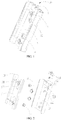
FIG. 1 is a structural schematic view of a cover assembly according to a first embodiment of the present application. -
FIG. 2 is an exploded view of the cover assembly ofFIG. 1 ; -
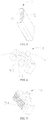
FIG. 3 is a structural schematic view of a cover of the cover assembly ofFIG. 2 , as viewed from another aspect; -
FIG. 4 is a structural schematic view of a locking member of the cover assembly ofFIG. 2 ; -
FIG. 5 is a structural schematic view of the locking member ofFIG. 2 , as viewed from another aspect; -
FIG. 6 is a structural schematic view of a battery assembly incorporated with the cover assembly ofFIG. 1 of the present application (the cover is locked); -
FIG. 7 is a structural schematic view of the battery assembly ofFIG. 6 in another state (the cover is unlocked); -
FIG. 8 is a structural schematic view of the battery assembly ofFIG. 6 in another state (the cover is pressed); and -
FIG. 9 is a structural schematic view of a battery assembly according to a second embodiment of the present application (the cover is locked). - The part names and their reference signs in the figures are:
battery assembly battery main body 10control board 20cover assembly 30inner lining member 31cover 32connecting member 33first elastic member 34locking structure 35mounting groove 101locking portion 102switch 201restricting hole 311through hole 312connecting hole 321abutting member 322positioning groove 323locking member 351second elastic member 352restricting member 353engaging portion 3511positioning post 3512restricting portion 3513prodding portion 3514fastener 313protrusion 314cutout 324indentation 3515abutting portion 331first flat surface 3221second flat surface 3222 - The present application will now be described in detail in conjunction with the drawings. These drawings are simplified schematic diagrams illustrating the basic structure of the present application only in a schematic manner, and thus they show only the configuration related to the present application.
- Referring to
FIG. 1 andFIG.6 , abattery assembly 100 configured for an electronic cigarette is provided by the present application. Thebattery assembly 100 includes a batterymain body 10, and acontrol board 20 and acover assembly 30 both of which are mounted on the batterymain body 10. In the embodiment, it is specified that, a direction away from an axial direction of the batterymain body 10 is defined as an outward direction. - The battery
main body 10 is provided with a mountinggroove 101, a sidewall of the mountinggroove 101 is provided with a lockingportion 102. In the embodiment, the lockingportion 102 is a locking groove defined in the sidewall of the mountinggroove 101. - The
control board 20 is fixedly mounted on the bottom wall of the mountinggroove 101. Thecontrol board 20 is provided with a pair ofswitches 201 electrically connected to the batterymain body 10. In the embodiment, theswitch 201 is an elastic switch. When theswitch 201 is pressed to be closed, the batterymain body 10 supplies power externally. - The
cover assembly 30 includes aninner lining member 31, acover 32, a connectingmember 33, a firstelastic member 34, and a lockingstructure 35. - Referring to
FIG. 2 andFIG. 6 , theinner lining member 31 is fixedly mounted in the mountinggroove 101 of the batterymain body 10. It can be understood that, theinner lining member 31 may be fixedly mounted to the batterymain body 10 through threaded connection, adhering connection or clamping connection. In the embodiment, theinner lining member 31 is provided with a threaded hole at the end opposite to the lockingportion 102. Theinner lining member 31 is fixedly mounted to the batterymain body 10 through fasteners such as screw or bolt. In the embodiment, in order to prevent the end of theinner lining member 31 opposite to the threaded hole disengaging from the mountinggroove 101, the end of theinner lining member 31 opposite to the threaded hole is provided with aprotrusion 314. In assembly, theprotrusion 314 is firstly engaged in the mountinggroove 101, and the end of theinner lining member 31 with the threaded hole is then fixedly mounted to the batterymain body 10 through fasteners such as screw or bolt, thereby theinner lining member 31 is stably mounted. - Referring to
FIG. 2 , theinner lining member 31 substantially has a planar shape, theinner lining member 31 is provided with a pair of restrictingholes 311 and a pair of throughholes 312. The pair of restrictingholes 311 are positioned on opposite ends of theinner lining member 31. One throughhole 312 is positioned adjacent to one restrictinghole 311, the other throughhole 312 is positioned adjacent to the other restrictinghole 311. Each throughhole 312 corresponds to oneswitch 201. - The
cover 32 is assembled to theinner lining member 31 and positioned outside theinner lining member 31. Thecover 32 is provided with a pair of connectingholes 321 corresponding to the pair of restrictingholes 311. A pair of abuttingmembers 322 corresponding to the pair of throughholes 312 are fixedly connected with thecover 32. Each abuttingmember 322 corresponds to a throughhole 312. Thecover 32 is movable toward or away from theinner lining member 31. When thecover 32 is pressed to move toward theinner lining member 31, the abuttingmember 322 is driven to resist theswitch 201, causing theswitch 201 to be in a closed state. In the embodiment, the abuttingmember 322 is formed by protruding inwardly from thecover 32. - Further, referring to
FIG. 3 , thecover 32 is provided with apositioning groove 323 corresponding to the lockingportion 102. - In order to clearly describe a connection relationship of the connecting
member 33, it is specified that, the end of the connectingmember 33 away from the batterymain body 10 is defined as the outer end, and the end of the connectingmember 33 opposite to the outer end is defined as the inner end. Referring toFIG. 6 , the inner end of the connectingmember 33 extends outwardly from a periphery of the connectingmember 33 to form an abuttingportion 331 which is capable of being engaged in the restrictinghole 311. After the connectingmember 33 extends through the restrictinghole 311, the abuttingportion 331 is engaged in the restrictinghole 311. The outer end of the connectingmember 33 is fixedly connected to the connectinghole 321. Further, a diameter of the restrictinghole 311 is greater than an outer diameter of the connectingmember 33, enabling the connectingmember 33 to move with thecover 32 when thecover 32 is pressed. In the embodiment, the connectingmember 33 is a screw. A larger end of the screw is the abuttingportion 331, a smaller end of the screw is threaded to thecover 32. Therefore, by providing the connectingmember 33, thecover 32 is connected to theinner lining member 31. - The first
elastic member 34 is provided between theinner lining member 31 and thecover 32, one end of the firstelastic member 34 elastically abuts theinner lining member 31, the other end of the firstelastic member 34 elastically abuts thecover 32. In a natural state, thecover 32 is positioned away from theinner lining member 31 under the elastic force provided by the firstelastic member 34, and at this time, theswitch 201 is separated from the abuttingmember 322. - In the embodiment, the first
elastic member 34 is a spring, and a quantity of the firstelastic member 34 is two. Eachelastic member 34 is sleeved on a corresponding abuttingmember 322. The abuttingmember 322 can provide a restricting function for the firstelastic member 34, guaranteeing the firstelastic member 34 to be abutted between theinner lining member 31 and thecover 32. - The locking
structure 35 includes a lockingmember 351, a secondelastic member 352, and a restrictingmember 353. - Referring to
FIG. 4 and FIG. 5 , the lockingmember 351 is movably positioned in thepositioning groove 323 of thecover 32. One end of the secondelastic member 352 elastically abuts a bottom wall of thepositioning groove 323, and the other end of the secondelastic member 352 elastically abuts a lower end of the lockingmember 351. An upper end of the lockingmember 351 is provided with an engagingportion 3511 corresponding to the lockingportion 102. In a natural state, the upper end of the engagingportion 3511 is engaged in the lockingportion 102 under the elastic force exerted on the lockingmember 351 by the secondelastic member 352, and the lower end of the lockingmember 351 is positioned in thepositioning groove 323. When the lockingmember 351 is prodded downward, the secondelastic member 352 is compressed, and the engagingportion 3511 is disengaged from the lockingportion 102. In the embodiment, the engagingportion 3511 is a protrusion. - It can be understood that, in an alternative embodiment not shown, the engaging
portion 3511 can be omitted. At this case, the upper end of the lockingmember 351 can be engaged with the lockingportion 102. In a natural state of the secondelastic member 352, the upper end of the lockingmember 351 engages with the lockingportion 102. - Further, in order to prod the locking
member 351 more easily, a proddingportion 3514 extends outwardly from an outer side edge of the lockingmember 351 and protrudes out of thecover 32. Thecover 32 defines acutout 324 corresponding to theprodding portion 3514. When the proddingportion 3514 of the lockingmember 351 is prodded downward along thecutout 324, the lockingmember 351 is driven to compress the secondelastic member 352. - In the embodiment, a
positioning post 3512 is provided at the lower end of the lockingmember 351, the secondelastic member 352 is a spring, and the secondelastic member 352 is sleeved on thepositioning post 3512, for providing a restricting function. - It can be understood that, the first
elastic member 34 and the secondelastic member 352 can also be other members having rigidity and elasticity, such as thin steel sheets. - The restricting
member 353 is fixedly mounted on a sidewall of thepositioning groove 323 of thecover 32 adjacent to the batterymain body 10. Referring toFIG. 4 , the lockingmember 351 is further provided with a restrictingportion 3513, the restrictingmember 353 can resist on one side of the restrictingportion 3513 adjacent to the lockingportion 102, thereby avoiding a disengagement of the lockingmember 351 from thepositioning groove 323. In the embodiment, the restrictingmember 353 is a pin, the restrictingportion 3513 is a plate substantially located at a middle of the lockingmember 351. In the embodiment, in order to facilitate the restrictingmember 353 to resist the restrictingportion 3513, the restrictingportion 3513 defines anindentation 3515 matching with the restrictingmember 353. Meanwhile, when the proddingportion 3514 is prodded downward, the upper end of the lockingmember 351 adjacent to the lockingportion 102 can resist the restrictingmember 353 for preventing a disengagement. - An operation procedure of the
battery assembly 100 of the present application is specifically described with reference to the accompanying drawings. - Referring to
FIG. 7 , when the user wants thebattery assembly 100 to provide power externally, the proddingportion 3514 is firstly prodded downward, causing theprodding portion 3514 to drive the lockingmember 351 to move downwardly and compress the secondelastic member 352, until the engagingportion 3511 at the upper end of the lockingmember 351 disengages from the lockingportion 102 of the batterymain body 10, and thus thecover 32 is unlocked. Referring toFIG. 8 , thecover 32 is then pressed inwardly, thecover 32 with the lockingstructure 35 moves toward theinner lining member 31 to compress the firstelastic member 34, until the abuttingmember 322 of thecover 32 extends through the throughhole 312 of theinner lining member 31 to resist theswitch 201 of thecontrol board 20, causing theswitch 201 to be closed. At this moment, the circuit is switched on. The atomizing core starts to work and atomizes the tobacco liquid to generate smoke. - When the user does not want the
battery assembly 100 to provide power externally, thecover 32 is released, thecover 32 with the lockingstructure 35 resets and moves outwardly under the action of the firstelastic member 34. The abuttingmember 322 gradually moves away and is finally separated from theswitch 201. When thecover 32 moves to a position in which the engagingportion 3511 of the lockingmember 351 is aligned with the lockingportion 102 of the batterymain body 10, the lockingmember 351 with the engagingportion 3511 moves upward under the action of the secondelastic member 352, causing the engagingportion 3511 to engage with the lockingportion 102, such that thecover 32 is locked and cannot be pressed toward theinner lining member 31. That is, thecover 32 returns again to the state as shown inFIG. 1 . - It can be understood that, in an alternative embodiment not shown, the
inner lining member 31 and the connectingmember 33 both can be omitted. At this case, one end of the firstelastic member 34 is fixedly connected to thecontrol board 20, and the other end of the firstelastic member 34 is fixedly connected to thecover 32, theswitch 201 corresponding to the abuttingmember 322 is provided on thecontrol board 20 and electrically connected to the batterymain body 10. As such, thecover 32 can also be pressed and released, and thecover 32 is kept from falling off. The structure is simpler and easier to manufacture. - It can be understood that, the
switch 201 and the abuttingmember 322 each can be only one. - In the
battery assembly 100 of the present application, by providing the lockingstructure 35, it is required to prod the lockingmember 351 firstly, to unlock thecover 32 before pressing thecover 32. Further, after thebattery assembly 100 is used, thecover 32 is released, and thecover 32 can reset automatically to be locked again by the lockingstructure 35. Thus, unintended activating or smoking the electronic cigarette by children is avoided, thereby having a certain children protection function. - The present application further provides an electronic cigarette. Since the electronic cigarette has all the technical features of the
aforementioned battery assembly 100, the electronic cigarette has the same technical effects as theaforementioned battery assembly 100. - Referring to
FIG. 9 , compared to thebattery assembly 100 of the first embodiment, thebattery assembly 200 in the second embodiment is different in that, the firstelastic member 34 is omitted, and meanwhile, the abuttingmember 322 is a member having elasticity and rigidity. One end of the abuttingmember 322 elastically abuts theswitch 201, and the other end of the abuttingmember 322 elastically abuts thecover 32. In order to prevent the abuttingmember 322 from falling off from theswitch 201 and thecover 32, and to avoid affecting the normal function of the abuttingmember 322 abutting against theswitch 201 and thecover 32, in the embodiment, one end of the abuttingmember 322 is fixedly connected to thecover 32. - In the embodiment, the abutting
member 322 is a thin steel sheet having a cross-section with a curved shape, one end of the abuttingmember 322 elastically abutting thecover 32 is provided with a firstflat surface 3221, and the firstflat surface 3221 is fixedly connected to thecover 32. The other end of the abuttingmember 322 elastically abutting theswitch 201 is provided with a secondflat surface 3222, and the secondflat surface 3222 contacts with theswitch 201. By surface to surface contact, the stability of connection is improved, for facilitating the abuttingmember 322 to work stably. - Specifically, when the
cover 32 is not pressed, i.e., the abuttingmember 322 is in a natural state, although the abuttingmember 322 contacts with theswitch 201, the elastic force of the abuttingmember 322 is not enough to drive theswitch 201 to be closed, and the batterymain body 10 does not supply power externally. When thecover 32 is pressed, a deformation of the abuttingmember 322 gradually increases, so that an elastic force of the abuttingmember 322 gradually increases, until the abuttingmember 322 resists theswitch 201 to be closed, and the batterymain body 10 supplies power externally. When thecover 32 is released, thecover 32 resets under the elastic force of the abuttingmember 322, causing theswitch 201 to be opened. - In the
battery assembly 200 of the second embodiment, the firstelastic member 34 is omitted, the abuttingmember 322 not only provides an action to close theswitch 201, but also provides an action to reset thecover 32. It has a simpler structure, being easy to manufacture. - Inspired by the above embodiments of the present application, the relevant persons can make various changes and modifications without deviating from the scope of the present application. The scope of the present application is not limited to the contents of the specification, and its scope must be determined according to the appended claims.
Claims (10)
- A battery assembly comprising a battery main body and a cover assembly arranged on the battery main body, wherein the battery main body is provided with a mounting groove, a sidewall of the mounting groove is provided with a locking portion, a switch is electrically connected to the battery main body, the cover assembly comprises a cover movably arranged in the mounting groove, a locking structure arranged on the cover, and an abutting member arranged, corresponding to the switch, between the mounting groove and the cover, the locking structure comprises a locking member movably arranged on the cover corresponding to the locking portion, and a second elastic member elastically abutting between the cover and the locking member; when the locking member is prodded to cause the locking member to unlock from the locking portion, the cover is capable of being pressed to cause the abutting member to resist the switch to be closed; when the cover is released, the cover resets, and the locking member resets under the action of the second elastic member to be locked with the locking portion.
- The battery assembly according to claim 1, wherein one end of the abutting member away from the battery main body is fixedly connected to the cover, the cover assembly further comprises a first elastic member elastically provided between the battery main body and the cover; when the cover is pressed, the cover compresses the first elastic member and drives the abutting member to move, causing the abutting member to resist the switch; when the cover is released, the cover resets under the action of the first elastic member and drives the abutting member to move, causing the abutting member to separate from the switch.
- The battery assembly according to claim 1, wherein one end of the abutting member elastically abuts the switch, and the other end of the abutting member elastically abuts the cover; when the cover is pressed, the abutting member is deformed to resist the switch to be closed; when the cover is released, the abutting member resets to cause the switch to be opened.
- The battery assembly according to claim 2 or 3, wherein the cover is provided with a positioning groove corresponding to the locking portion, the locking member is movably positioned in the positioning groove, one end of the second elastic member elastically abuts a bottom wall of the positioning groove away from the locking portion, the other end of the second elastic member elastically abuts the locking member.
- The battery assembly according to claim 4, wherein the locking structure further comprises a restricting member, the restricting member is fixedly connected to a sidewall of the positioning groove adjacent to the battery main body, the locking member is provided with a restricting portion, the restricting member resists on one side of the restricting portion adjacent to the locking portion.
- The battery assembly according to claim 1, wherein the locking member is provided with an engaging portion corresponding to and engageable with the locking portion, the engaging portion is engaged with the locking portion under the action of the second elastic member.
- The battery assembly according to claim 4, wherein the cover assembly further comprises an inner lining member fixedly mounted in the mounting groove and a connecting member provided between the inner lining member and the cover, the inner lining member is positioned at a side of the cover adjacent to the battery main body, the cover is connected to the inner lining member by the connecting member.
- The battery assembly according to claim 7, wherein the inner lining member is provided with a restricting hole, the cover is provided with a connecting hole corresponding to the restricting hole, one end of the connecting member extends outwardly from a periphery of the connecting member to form an abutting portion which is capable of being engaged in the restricting hole, after the connecting member extends through the restricting hole, the abutting portion is engaged in the restricting hole, the other end of the connecting member opposite to the abutting portion is fixedly connected to the cover.
- The battery assembly according to claim 8, wherein the inner lining member is provided with a through hole, the through hole corresponds to the switch, the abutting member extends through the through hole to resist the switch.
- An electronic cigarette comprising the battery assembly according to either one of claims 1 to 9.
Applications Claiming Priority (2)
| Application Number | Priority Date | Filing Date | Title |
|---|---|---|---|
| CN201621390005.0U CN206250251U (en) | 2016-12-16 | 2016-12-16 | A kind of battery component and its electronic cigarette |
| PCT/CN2017/116649 WO2018108171A1 (en) | 2016-12-16 | 2017-12-15 | Battery assembly and electronic cigarette with same |
Publications (2)
| Publication Number | Publication Date |
|---|---|
| EP3557650A1 true EP3557650A1 (en) | 2019-10-23 |
| EP3557650A4 EP3557650A4 (en) | 2020-07-15 |
Family
ID=59008404
Family Applications (1)
| Application Number | Title | Priority Date | Filing Date |
|---|---|---|---|
| EP17879813.8A Withdrawn EP3557650A4 (en) | 2016-12-16 | 2017-12-15 | Battery assembly and electronic cigarette with same |
Country Status (4)
| Country | Link |
|---|---|
| US (1) | US11103010B2 (en) |
| EP (1) | EP3557650A4 (en) |
| CN (1) | CN206250251U (en) |
| WO (1) | WO2018108171A1 (en) |
Families Citing this family (6)
| Publication number | Priority date | Publication date | Assignee | Title |
|---|---|---|---|---|
| CN206250251U (en) * | 2016-12-16 | 2017-06-13 | 常州市派腾电子技术服务有限公司 | A kind of battery component and its electronic cigarette |
| CN207167765U (en) * | 2017-07-17 | 2018-04-03 | 常州市派腾电子技术服务有限公司 | A kind of atomizer and its electronic cigarette |
| FR3104827B1 (en) * | 2019-12-17 | 2023-05-19 | Renault Sas | MOTOR VEHICLE BATTERY ASSEMBLY COMPRISING INTERLOCKED MEANS FOR PROTECTING THE TWO TERMINAL TERMINALS |
| TW202215996A (en) * | 2020-10-16 | 2022-05-01 | 瑞士商傑太日煙國際股份有限公司 | Aerosol generation device with cover and insulating air gap |
| DE102022113398A1 (en) * | 2022-05-27 | 2023-11-30 | Wacker Neuson Produktion GmbH & Co. KG | Spring element and locking device for battery holder |
| CN115942680B (en) * | 2023-02-27 | 2025-04-29 | 西安易朴通讯技术有限公司 | Self-locking handle and chassis |
Family Cites Families (13)
| Publication number | Priority date | Publication date | Assignee | Title |
|---|---|---|---|---|
| JPH0280929U (en) * | 1988-12-12 | 1990-06-21 | ||
| JP4217546B2 (en) * | 2003-06-12 | 2009-02-04 | 株式会社東海理化電機製作所 | switch |
| JP4456012B2 (en) * | 2005-01-24 | 2010-04-28 | 株式会社東海理化電機製作所 | Switch device |
| FR2924858B1 (en) * | 2007-12-06 | 2011-04-01 | Coactive Technologies Inc | ELECTRICAL SWITCH WITH SIDE ACTUATION AND ASSEMBLY COMPRISING SUCH A SWITCH |
| AT507187B1 (en) * | 2008-10-23 | 2010-03-15 | Helmut Dr Buchberger | INHALER |
| CN204409582U (en) * | 2012-09-17 | 2015-06-24 | 惠州市吉瑞科技有限公司 | Electronic hookah |
| WO2015039275A1 (en) * | 2013-09-17 | 2015-03-26 | 吉瑞高新科技股份有限公司 | Battery component and electronic cigarette |
| CN204088411U (en) | 2014-06-30 | 2015-01-07 | 深圳市麦克韦尔科技有限公司 | For battery component and the electronic cigarette of electronic cigarette |
| CN105789506B (en) * | 2015-12-24 | 2018-04-17 | 深圳瀚星翔科技有限公司 | Electronic cigarette battery |
| CN205595379U (en) | 2016-01-06 | 2016-09-21 | 深圳麦克韦尔股份有限公司 | Battery device of electron cigarette |
| CN205456059U (en) | 2016-01-18 | 2016-08-17 | 卓尔悦欧洲控股有限公司 | Spring locking mechanism , atomizer and electron cigarette of electron cigarette |
| CN205624465U (en) * | 2016-02-29 | 2016-10-12 | 深圳市菲美特科技有限公司 | battery for electronic cigarette |
| CN206250251U (en) | 2016-12-16 | 2017-06-13 | 常州市派腾电子技术服务有限公司 | A kind of battery component and its electronic cigarette |
-
2016
- 2016-12-16 CN CN201621390005.0U patent/CN206250251U/en active Active
-
2017
- 2017-12-15 WO PCT/CN2017/116649 patent/WO2018108171A1/en not_active Ceased
- 2017-12-15 US US16/469,051 patent/US11103010B2/en not_active Expired - Fee Related
- 2017-12-15 EP EP17879813.8A patent/EP3557650A4/en not_active Withdrawn
Also Published As
| Publication number | Publication date |
|---|---|
| US20200099020A1 (en) | 2020-03-26 |
| US11103010B2 (en) | 2021-08-31 |
| WO2018108171A1 (en) | 2018-06-21 |
| CN206250251U (en) | 2017-06-13 |
| EP3557650A4 (en) | 2020-07-15 |
Similar Documents
| Publication | Publication Date | Title |
|---|---|---|
| CN206250251U (en) | A kind of battery component and its electronic cigarette | |
| US9761384B2 (en) | Shift assembly structure of switch device | |
| US8245986B2 (en) | Support stand | |
| WO2016026105A1 (en) | Switch mechanism of electronic cigarette | |
| WO2024007255A1 (en) | Intelligent wall switch, wireless intelligent switch and switch mounting rack | |
| US8263888B2 (en) | Power button assembly and electronic device using the same | |
| CN209819796U (en) | Micro-gap switch's connection structure and air conditioner | |
| CN103531377A (en) | Switch with power-off protection | |
| CN206584988U (en) | Cell apparatus and its electronic cigarette | |
| CN202277254U (en) | Double anti-blocking protection structure of toaster | |
| TWM563487U (en) | Buckle structure | |
| CN210136933U (en) | Battery quick detach structure | |
| CN209744641U (en) | Air conditioner and emergency switch assembly thereof | |
| TW201824315A (en) | Button assembly and electronic device using the same | |
| CN210110877U (en) | Battery installation component | |
| CN201845674U (en) | Multifunctional switch handle | |
| CN205728056U (en) | Atomising device and the electronic cigarette with this atomising device | |
| US20120087070A1 (en) | Portable electronic device | |
| CN222619994U (en) | Locking device and remote control | |
| CN204204678U (en) | Panel-switch | |
| TW202203518A (en) | Electronic device and sealing structure thereof | |
| CN221076733U (en) | Humidifier | |
| CN222260517U (en) | Music playing device used with cans and can with music playing device | |
| CN222603776U (en) | Battery assembly, host assembly, atomizing host and electronic atomizing device | |
| CN221127349U (en) | Shell assembly and electronic equipment |
Legal Events
| Date | Code | Title | Description |
|---|---|---|---|
| PUAI | Public reference made under article 153(3) epc to a published international application that has entered the european phase |
Free format text: ORIGINAL CODE: 0009012 |
|
| 17P | Request for examination filed |
Effective date: 20190702 |
|
| AK | Designated contracting states |
Kind code of ref document: A1 Designated state(s): AL AT BE BG CH CY CZ DE DK EE ES FI FR GB GR HR HU IE IS IT LI LT LU LV MC MK MT NL NO PL PT RO RS SE SI SK SM TR |
|
| AX | Request for extension of the european patent |
Extension state: BA ME |
|
| DAV | Request for validation of the european patent (deleted) | ||
| DAX | Request for extension of the european patent (deleted) | ||
| A4 | Supplementary search report drawn up and despatched |
Effective date: 20200615 |
|
| RIC1 | Information provided on ipc code assigned before grant |
Ipc: A24F 47/00 20200101ALI20200608BHEP Ipc: H01M 2/10 20060101AFI20200608BHEP |
|
| STAA | Information on the status of an ep patent application or granted ep patent |
Free format text: STATUS: THE APPLICATION HAS BEEN WITHDRAWN |
|
| 18W | Application withdrawn |
Effective date: 20201104 |