EP3557554B1 - Vehicle hazard management system - Google Patents
Vehicle hazard management system Download PDFInfo
- Publication number
- EP3557554B1 EP3557554B1 EP19163399.9A EP19163399A EP3557554B1 EP 3557554 B1 EP3557554 B1 EP 3557554B1 EP 19163399 A EP19163399 A EP 19163399A EP 3557554 B1 EP3557554 B1 EP 3557554B1
- Authority
- EP
- European Patent Office
- Prior art keywords
- vehicle
- management system
- emergency
- emergency message
- controller
- Prior art date
- Legal status (The legal status is an assumption and is not a legal conclusion. Google has not performed a legal analysis and makes no representation as to the accuracy of the status listed.)
- Active
Links
Images

Classifications
-
- G—PHYSICS
- G07—CHECKING-DEVICES
- G07C—TIME OR ATTENDANCE REGISTERS; REGISTERING OR INDICATING THE WORKING OF MACHINES; GENERATING RANDOM NUMBERS; VOTING OR LOTTERY APPARATUS; ARRANGEMENTS, SYSTEMS OR APPARATUS FOR CHECKING NOT PROVIDED FOR ELSEWHERE
- G07C5/00—Registering or indicating the working of vehicles
- G07C5/008—Registering or indicating the working of vehicles communicating information to a remotely located station
-
- B—PERFORMING OPERATIONS; TRANSPORTING
- B60—VEHICLES IN GENERAL
- B60L—PROPULSION OF ELECTRICALLY-PROPELLED VEHICLES; SUPPLYING ELECTRIC POWER FOR AUXILIARY EQUIPMENT OF ELECTRICALLY-PROPELLED VEHICLES; ELECTRODYNAMIC BRAKE SYSTEMS FOR VEHICLES IN GENERAL; MAGNETIC SUSPENSION OR LEVITATION FOR VEHICLES; MONITORING OPERATING VARIABLES OF ELECTRICALLY-PROPELLED VEHICLES; ELECTRIC SAFETY DEVICES FOR ELECTRICALLY-PROPELLED VEHICLES
- B60L3/00—Electric devices on electrically-propelled vehicles for safety purposes; Monitoring operating variables, e.g. speed, deceleration or energy consumption
- B60L3/0007—Measures or means for preventing or attenuating collisions
-
- B—PERFORMING OPERATIONS; TRANSPORTING
- B60—VEHICLES IN GENERAL
- B60R—VEHICLES, VEHICLE FITTINGS, OR VEHICLE PARTS, NOT OTHERWISE PROVIDED FOR
- B60R21/00—Arrangements or fittings on vehicles for protecting or preventing injuries to occupants or pedestrians in case of accidents or other traffic risks
- B60R21/01—Electrical circuits for triggering passive safety arrangements, e.g. airbags, safety belt tighteners, in case of vehicle accidents or impending vehicle accidents
- B60R21/013—Electrical circuits for triggering passive safety arrangements, e.g. airbags, safety belt tighteners, in case of vehicle accidents or impending vehicle accidents including means for detecting collisions, impending collisions or roll-over
- B60R21/0136—Electrical circuits for triggering passive safety arrangements, e.g. airbags, safety belt tighteners, in case of vehicle accidents or impending vehicle accidents including means for detecting collisions, impending collisions or roll-over responsive to actual contact with an obstacle, e.g. to vehicle deformation, bumper displacement or bumper velocity relative to the vehicle
-
- G—PHYSICS
- G01—MEASURING; TESTING
- G01R—MEASURING ELECTRIC VARIABLES; MEASURING MAGNETIC VARIABLES
- G01R31/00—Arrangements for testing electric properties; Arrangements for locating electric faults; Arrangements for electrical testing characterised by what is being tested not provided for elsewhere
- G01R31/005—Testing of electric installations on transport means
- G01R31/006—Testing of electric installations on transport means on road vehicles, e.g. automobiles or trucks
-
- G—PHYSICS
- G07—CHECKING-DEVICES
- G07C—TIME OR ATTENDANCE REGISTERS; REGISTERING OR INDICATING THE WORKING OF MACHINES; GENERATING RANDOM NUMBERS; VOTING OR LOTTERY APPARATUS; ARRANGEMENTS, SYSTEMS OR APPARATUS FOR CHECKING NOT PROVIDED FOR ELSEWHERE
- G07C5/00—Registering or indicating the working of vehicles
- G07C5/08—Registering or indicating performance data other than driving, working, idle, or waiting time, with or without registering driving, working, idle or waiting time
- G07C5/0808—Diagnosing performance data
-
- G—PHYSICS
- G08—SIGNALLING
- G08B—SIGNALLING SYSTEMS, e.g. PERSONAL CALLING SYSTEMS; ORDER TELEGRAPHS; ALARM SYSTEMS
- G08B25/00—Alarm systems in which the location of the alarm condition is signalled to a central station, e.g. fire or police telegraphic systems
- G08B25/01—Alarm systems in which the location of the alarm condition is signalled to a central station, e.g. fire or police telegraphic systems characterised by the transmission medium
- G08B25/016—Personal emergency signalling and security systems
-
- G—PHYSICS
- G08—SIGNALLING
- G08G—TRAFFIC CONTROL SYSTEMS
- G08G1/00—Traffic control systems for road vehicles
- G08G1/20—Monitoring the location of vehicles belonging to a group, e.g. fleet of vehicles, countable or determined number of vehicles
- G08G1/205—Indicating the location of the monitored vehicles as destination, e.g. accidents, stolen, rental
-
- B—PERFORMING OPERATIONS; TRANSPORTING
- B60—VEHICLES IN GENERAL
- B60R—VEHICLES, VEHICLE FITTINGS, OR VEHICLE PARTS, NOT OTHERWISE PROVIDED FOR
- B60R21/00—Arrangements or fittings on vehicles for protecting or preventing injuries to occupants or pedestrians in case of accidents or other traffic risks
- B60R2021/0027—Post collision measures, e.g. notifying emergency services
Definitions
- the present disclosure generally relates to alternative fuel vehicles ("AFVs”) and more particularly to systems for managing hazards associated with such AFVs.
- AFVs alternative fuel vehicles
- AFVs include, for example, electric vehicles, hybrid vehicles, fuel cell vehicles and gaseous fuel vehicles.
- vehicle manufacturers provide emergency response guides for use by first and second responders that provide vehicle and safety information unique to the particular AFV.
- collections of these emergency response guides are made available through websites hosted, for example, by the National Fire Protection Association. The guides vary based on the type of architecture, system(s) and component(s) used in the AFV.
- emergency responders are required to locate various badges or other identifiers on the AFV and/or to decode the VIN of the AFV to properly identify the vehicle make, model and year. After the AFV is properly identified, the emergency responder must then locate the corresponding emergency response guide.
- time is of the essence, and any delays in identifying the AFV and accessing the corresponding emergency response guide may result in further property damage, more severe injuries or even death.
- AFVs when water is involved, the dangers presented by AFVs, particularly those with high voltage systems, may be even more severe. It is well known that water is a good conductor of electricity and electric vehicles and hybrid vehicles store large amounts of electrical energy in on-board batteries. The emergency response guides for such AFVs instruct the emergency responders how to safely treat the vehicles when water is involved, which may occur as a result of flooding or driver error. Many AFVs have a high voltage service disconnect and/or an emergency disconnect which must be accessed by the emergency responders. While some AFVs include a high voltage battery that discharges automatically when a collision is detected such as by a motion detector, not all AFVs include this feature. Additionally, some vehicles become at least partially submerged in water as a result of flooding or other events, where no collision occurs.
- US2012146766A1 relates to a method of processing vehicle crash data including the steps of receiving vehicle data obtained at a vehicle during a vehicle crash, determining the identity of the vehicle, estimating the severity of the vehicle crash using the determined vehicle identity and the received vehicle data, and providing the estimated severity to an emergency responder.
- JP5974888B2 relates to determining vehicle collision on the basis of a change in a vehicle speed V at the time of communication cut-off when that occurs, to discharge, by using a discharge circuit, a charge stored in a smoothing capacitor.
- US2015051771A1 relates to a system for discharging the electric charge stored in a battery of an electric/ hybrid vehicle, upon receiving a signal indicative of the occurrence of a vehicle event such as a flood, a crash or a failure of electrical isolation.
- US2015108951A1 relates to an in-vehicle power storage device that discharges a battery in a case where collision of a vehicle is detected or predicted, and stops discharging the battery when an over-discharged state has not been reached.
- US2014021914A1 discloses a method for managing battery charging of an electric vehicle docked to a charging station accommodating the vehicle to be charged through induction. The method involves monitoring the temperature in the area near the induction charging plates, such that if the sensed temperature has exceeded a threshold, the vehicle controller causes the charger to be disabled from providing power or causing the vehicle and the charger to lose association and charging of the battery to discontinue. When a battery charge procedure is already underway, the method includes interrupting the procedure in response to an object detection signal.
- a vehicle hazard management system as defined in claim 1.
- the present disclosure provides, among other things, systems for automatically communicating key information to emergency responders in the event of an AFV crash (as detected by a motion sensor, airbag system, seat belt pretensioning system, etc.), a catastrophic battery fault and/or a water immersion event.
- the key information that is automatically reported to responders may include the location of the vehicle, the vehicle make, model and year, information indicating whether the vehicle is a hybrid vehicle or an electric vehicle, and an emergency response guide corresponding to the vehicle or a link to an emergency response guide corresponding to the vehicle.
- the system permits the responders to identify and consult the emergency response guide corresponding to the vehicle either before leaving or while en route to the scene, and eliminates the delays associated with searching for vehicle badges, markings, VIN, etc. on the scene.
- emergency responders may suit up with appropriate personal protective equipment ("PPE") and prepare any other equipment needed for the response for the particular AFV involved in the incident in advance of arriving at the scene.
- PPE personal protective equipment
- AFVs are provided with a "black box" type device which in certain embodiments is heat resistant and capable of communicating wirelessly, via RF, or otherwise with an emergency responder device such as a computer in the emergency vehicle, a handheld device, a mobile phone, etc.
- an emergency responder device such as a computer in the emergency vehicle, a handheld device, a mobile phone, etc.
- the emergency responder device receives from the black box and then broadcasts, displays or otherwise communicates some or all of the following information: 1) a warning that the vehicle is an AFV; 2) the make, model and year of the AFV; and 3) appropriate emergency response guide information for the AFV.
- emergency responders can consult the appropriate emergency response guide and proceed safely with the response without having to search for vehicle identification information.
- a system that detects when an AFV has either driven into water and stopped or has become partially submerged in water when not in operation (e.g., parked in a lot that has become flooded).
- the system may automatically deactivate the batteries and switch to internal combustion power only and/or take action with the batteries, such as discharging them.
- This response may be particularly suitable for commercial AFVs due to the potentially greater height difference between the batteries and the engine as compared to a passenger AFV. Additionally, if the AFV has a range-extender, the system may discontinue providing charge to the batteries from the range-extender.
- the system may automatically deactivate the charging system.
- the system may communicate with other AFVs nearby to cause those AFVs to deactivate their charging system and/or to prepare their batteries to be discharged.
- a vehicle hazard management system 10 is shown in use with an AFV 12.
- System 10 generally includes a sensor 14, a controller 16 and a transmitter 18.
- AFV 12 generally includes a high voltage system 20 including a battery 22 (or collection of batteries), a DC-DC converter 24, a drive unit 26, a charge port 28 and a discharge device 30.
- the components of high voltage system 20 are connected via high voltage cabling 32.
- AFV 12 is depicted as a fully electric vehicle, it should be understood that the principles of the present disclosure apply equally to any type of AFV including hybrid vehicles, fuel cell vehicles, gaseous fuel vehicles and any other vehicle that presents hazards to emergency responders.
- electricity is supplied to battery 22 through charge port 28 using a conventional charging system.
- Battery 22 may include one or more cells that employ any of various suitable energy storage technologies such as lithium-ion batteries.
- Battery 22 provides the stored electricity to drive unit 26, which converts DC current into 3-phase AC current that one or more electric motors (not shown) use to power the rear wheels.
- DC-DC converter 24 transforms the high voltage current from battery 22 to low voltage for charging a standard 12 volt battery (not shown), which powers various components of AFV 12 such as the supplementary restraint system, ignition system, airbags, displays and lighting components.
- discharge device 30 causes battery 22 to discharge when activated by system 10.
- the electrical energy from battery 22 is drained through a resistive device such as a heater. As explained herein, discharge device 30 may cause battery 22 to discharge its energy before rising water reaches battery 22.
- Sensor 14 of system 10 may include one or more sensor devices as described herein, including a collision sensor and/or a water sensor.
- Sensor 14 may include one or more accelerometers or other motion detection devices that detect a sudden impact or may be integrated into an airbag system or seat belt pretensioning system of AFV 12 that provides collision detection functionality.
- sensor 14 provides an activation signal to controller 16 when an activation event occurs such as a collision, a fault involving battery 22, or at least a partial water submersion event.
- the activation signal initiates a response by system 10 in the manner described below.
- Controller 16 may be a stand-alone device or may be part of an Engine Control Module ("ECM”) in vehicles having internal combustion engines. Controller 16 may include one or more computing devices having memory, processing and communication hardware, firmware and/or software. Controller 16 may be a single device or a distributed device, and the functions of the controller may be performed by hardware and/or as computer instructions on a non-transient computer readable storage medium. As shown in FIG. 2 , in certain embodiments controller 16 may include an input interface 34, a processor 36, a memory device 38, a GPS unit 40, and an output interface 42. Input interface 34 communicates the activation signals from sensor 14 to processor 36. Processor 36 is programmed to respond to receipt of an activation signal by performing one or more of a variety of functions as described herein.
- ECM Engine Control Module
- processor 36 responds to receipt of an activation signal by generating an emergency message that is communicated by output interface 42 to transmitter 18.
- Processor 36 may generate an emergency message by accessing memory device 38 to obtain information stored in memory device 38 identifying the make, model and year of manufacture of AFV 12.
- Processor 36 may also access GPS unit 40 to obtain information regarding the current location of AFV 12, and include such location information in the emergency message.
- output interface 42 of controller 16 communicates emergency messages to transmitter 18.
- Transmitter 18 may transmit the emergency messages wirelessly, as radio waves configured to be received by a conventional cell phone tower 44.
- the emergency messages are transmitted to an intended recipient such as an emergency responder communication device 46.
- emergency responder communication device 46 may be a 911 system, an emergency responder dispatch system, an emergency responder radio or cell phone, or other device that functions to provide information to one or more first and/or second responders.
- Emergency responder communication device 46 may communicate the emergency messages to one or more additional emergency responder devices 46. In this manner, emergency responders at, for example, a fire station, may be immediately alerted of an emergency situation involving AFV 12, and provided location and identification information regarding the AFV 12.
- the emergency responders may use this information to locate the emergency response manual corresponding to the AFV 12 involved in the emergency, such as by accessing the emergency response manual on line.
- the emergency responders may use the information from the emergency response manual to suit up with PPE appropriate for the situation and/or bring other equipment that may be useful in addressing the emergency situation (e.g., fans, SCBA equipment, etc.).
- the emergency responders may obtain the necessary equipment before departing for the location of AFV 12, and review the emergency response guide en route to AFV 12.
- many AFVs 12 include "no-cut zones" (e.g., areas occupied by high voltage system 20) which present serious risk of injury or death if pierced or otherwise damaged by victim extraction equipment.
- Emergency responders can identify these "no-cut zones" before arriving at the scene and be prepared to perform any extraction procedures in a manner that avoids these areas of AFV 12. In this manner, the delay associated with locating vehicle identification information, obtaining the appropriate emergency response guide and reviewing the emergency information at the scene of the emergency is eliminated.
- Controller 16 of system 10 may also, under appropriate circumstances, respond to receipt of an activation signal by activating discharge device 30, thereby causing discharge device 30 to discharge the stored energy in battery 22 as described herein.
- system 50 is configured as a "black box" type device mounted to AFV 12 and configured to withstand significant mechanical force (e.g., from a collision) and heat (e.g., from a fire resulting from a collision, malfunction of high voltage system 20, or otherwise).
- Sensor 14 and controller 16 may be substantially the same as those described above with reference to vehicle hazard management system 10.
- Transmitter 18A is configured as a local transmitter that communicates with emergency responder communication device 46 on the scene. As such, transmitter 18A may be configured to operate according to Bluetooth wireless protocols or other personal area network technologies. In this manner, when emergency responder communication device 46 comes within range of transmitter 18A, controller 16 provides emergency messages including the information described above directly to emergency responder communication device 46.
- system 50 eliminates the need for emergency responders to identify AFV 12 on site by locating badges and other physical identifiers
- system 50 does not provide some of the benefits of system 10 in that preparations cannot be made based on emergency messages prior to dispatch of the emergency responders or while en route to the scene.
- system 10 may be unable to transmit emergency messages.
- System 50 at least provides the emergency messages to responders arriving at the scene.
- AFV 12 is provided with both system 10 and system 50.
- such a combined system may combine redundant components and/or otherwise consolidate features and functionality.
- System 60 generally includes a water sensor 62, a controller 64 and a discharge device 66.
- AFV 12 is a hybrid vehicle including an internal combustion engine 68 and a battery 22 (other components of high voltage system 20 are not shown).
- AFV 12 is shown partially submerged in water 70.
- water sensor 62 is positioned to detect water 70 when the level of the water approaches engine 68, and before water 70 reaches battery 22. This may occur when AFV 12 drives through deep water or is parked in an area that becomes flooded.
- Controller 64 may respond to the activation signal by automatically deactivating battery 22 or automatically activating discharge device 66 which discharges battery 22, and thereby causes AFV 12 to operate only on mechanical power provided by engine 68.
- FIG. 5 depicts yet another embodiment of a vehicle hazard management system 80 according to the principles of the present disclosure.
- System 80 includes a water sensor 82, a controller 16 and a transmitter 18B and is designed to deactivate a charging station 84 coupled to charge port 28 of high voltage system 20.
- Water sensor 82 is positioned to detect the presence of water 70 as the level of water approaches battery 22. When water sensor 82 detects water, it provides an activation signal to controller 16 in the manner described above. Sensor 16 responds to the activation signal by causing transmitter 18B, which may be a local transmitter similar to transmitter 18A of system 50 described above, to send a deactivation signal to charging station 84.
- Charging station 84 responds to receipt of such a deactivation signal by discontinuing charging of AFV 12.
- transmitter 18B is configured to transmit deactivation signals to other adjacent systems 80 mounted to nearby AFVs 12, such as in a situation where a fleet of vehicles are being charged in an area that is flooding.
- the adjacent systems 80 also transmit deactivation signals to their charging stations 84, causing those charging stations 84 to discontinue charging. In this manner, the first AFV 12 that experiences water submersion can cause all AFVs 12 in this fleet to discontinue charging, even before those AFVs 12 experience flooding.
- the modifier "about” used in connection with a quantity is inclusive of the stated value and has the meaning dictated by the context (for example, it includes at least the degree of error associated with the measurement of the particular quantity).
- the modifier "about” should also be considered as disclosing the range defined by the absolute values of the two endpoints. For example, the range “from about 2 to about 4" also discloses the range “from 2 to 4.”
- references to "one embodiment,” “an embodiment,” “an example embodiment,” etc. indicate that the embodiment described may include a particular feature, structure, or characteristic, but every embodiment may not necessarily include the particular feature, structure, or characteristic. Moreover, such phrases are not necessarily referring to the same embodiment. Further, when a particular feature, structure, or characteristic is described in connection with an embodiment, it is submitted that it is within the knowledge of one skilled in the art with the benefit of the present disclosure to affect such feature, structure, or characteristic in connection with other embodiments whether or not explicitly described. After reading the description, it will be apparent to one skilled in the relevant art(s) how to implement the disclosure in alternative embodiments.
Landscapes
- Engineering & Computer Science (AREA)
- Physics & Mathematics (AREA)
- General Physics & Mathematics (AREA)
- Mechanical Engineering (AREA)
- Emergency Management (AREA)
- Business, Economics & Management (AREA)
- Computer Security & Cryptography (AREA)
- Transportation (AREA)
- Power Engineering (AREA)
- Chemical & Material Sciences (AREA)
- Combustion & Propulsion (AREA)
- Sustainable Energy (AREA)
- Sustainable Development (AREA)
- Life Sciences & Earth Sciences (AREA)
- Electric Propulsion And Braking For Vehicles (AREA)
Description
- The present application claims the benefit of and priority to
U.S. Provisional Application S/ N 62/649,084, entitled "VEHICLE HAZARD MANAGEMENT SYSTEM," filed on March 28, 2018 - The present disclosure generally relates to alternative fuel vehicles ("AFVs") and more particularly to systems for managing hazards associated with such AFVs.
- Special training, tools and information are often required for emergency responders, such as the Fire Service and EMS, to safely handle emergency situations involving AFVs. Such AFVs include, for example, electric vehicles, hybrid vehicles, fuel cell vehicles and gaseous fuel vehicles. As the configuration of each AFV varies by make, model and year, vehicle manufacturers provide emergency response guides for use by first and second responders that provide vehicle and safety information unique to the particular AFV. Currently, collections of these emergency response guides are made available through websites hosted, for example, by the National Fire Protection Association. The guides vary based on the type of architecture, system(s) and component(s) used in the AFV.
- In general, emergency responders are required to locate various badges or other identifiers on the AFV and/or to decode the VIN of the AFV to properly identify the vehicle make, model and year. After the AFV is properly identified, the emergency responder must then locate the corresponding emergency response guide. Of course, in emergency situations such as fighting a fire or assisting injured people, time is of the essence, and any delays in identifying the AFV and accessing the corresponding emergency response guide may result in further property damage, more severe injuries or even death.
- Additionally, when water is involved, the dangers presented by AFVs, particularly those with high voltage systems, may be even more severe. It is well known that water is a good conductor of electricity and electric vehicles and hybrid vehicles store large amounts of electrical energy in on-board batteries. The emergency response guides for such AFVs instruct the emergency responders how to safely treat the vehicles when water is involved, which may occur as a result of flooding or driver error. Many AFVs have a high voltage service disconnect and/or an emergency disconnect which must be accessed by the emergency responders. While some AFVs include a high voltage battery that discharges automatically when a collision is detected such as by a motion detector, not all AFVs include this feature. Additionally, some vehicles become at least partially submerged in water as a result of flooding or other events, where no collision occurs.
- Thus, what is needed is an improved approach to enable emergency responders to quickly and safely respond to situations involving AFVs.
-
US2012146766A1 relates to a method of processing vehicle crash data including the steps of receiving vehicle data obtained at a vehicle during a vehicle crash, determining the identity of the vehicle, estimating the severity of the vehicle crash using the determined vehicle identity and the received vehicle data, and providing the estimated severity to an emergency responder. -
JP5974888B2 -
US2015051771A1 relates to a system for discharging the electric charge stored in a battery of an electric/ hybrid vehicle, upon receiving a signal indicative of the occurrence of a vehicle event such as a flood, a crash or a failure of electrical isolation. -
US2015108951A1 relates to an in-vehicle power storage device that discharges a battery in a case where collision of a vehicle is detected or predicted, and stops discharging the battery when an over-discharged state has not been reached. -
US2014021914A1 discloses a method for managing battery charging of an electric vehicle docked to a charging station accommodating the vehicle to be charged through induction. The method involves monitoring the temperature in the area near the induction charging plates, such that if the sensed temperature has exceeded a threshold, the vehicle controller causes the charger to be disabled from providing power or causing the vehicle and the charger to lose association and charging of the battery to discontinue. When a battery charge procedure is already underway, the method includes interrupting the procedure in response to an object detection signal. - According to one aspect of the present invention there is provided a vehicle hazard management system as defined in claim 1.
- According to another aspect of the invention there is provided a method of managing hazards associated with a vehicle having a high voltage system as defined in claim 11.
- Preferred features of the invention are recited in the dependent claims.
- The above-mentioned and other features of this disclosure and the manner of obtaining them will become more apparent and the disclosure itself will be better understood by reference to the following description of embodiments of the present disclosure taken in conjunction with the accompanying drawings, wherein;
-
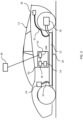
FIG. 1 is a schematic diagram of a vehicle hazard management system according to one embodiment of the present disclosure; -
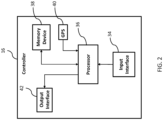
FIG. 2 is a block diagram of a controller of the system ofFIG. 1 ; -
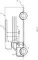
FIG. 3 is a schematic diagram of a vehicle hazard management system according to another embodiment of the present disclosure; -
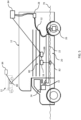
FIG. 4 is a schematic diagram of a vehicle hazard management system according to yet another embodiment of the present disclosure; and -
FIG. 5 is a schematic diagram of a vehicle hazard management system according to still another embodiment of the present disclosure. - Although the drawings represent embodiments of the various features and components according to the present disclosure, the drawings are not necessarily to scale and certain features may be exaggerated in order to better illustrate and explain the present disclosure. The exemplification set out herein illustrates embodiments of the disclosure, and such exemplifications are not to be construed as limiting the scope of the disclosure in any manner.
- For the purpose of promoting an understanding of the principles of the disclosure, reference will now be made to the embodiments illustrated in the drawings, which are described below. It will nevertheless be understood that no limitation of the scope of the disclosure is thereby intended. The disclosure includes any alterations and further modifications in the illustrated device and described methods and further applications of the principles of the disclosure, which would normally occur to one skilled in the art to which the disclosure relates. Moreover, the embodiments were selected for description to enable one of ordinary skill in the art to practice the disclosure.
- The present disclosure provides, among other things, systems for automatically communicating key information to emergency responders in the event of an AFV crash (as detected by a motion sensor, airbag system, seat belt pretensioning system, etc.), a catastrophic battery fault and/or a water immersion event. The key information that is automatically reported to responders (generally through 911 in the United States) may include the location of the vehicle, the vehicle make, model and year, information indicating whether the vehicle is a hybrid vehicle or an electric vehicle, and an emergency response guide corresponding to the vehicle or a link to an emergency response guide corresponding to the vehicle. By automatically communicating this information to the emergency responders at the time of the emergency event, the system permits the responders to identify and consult the emergency response guide corresponding to the vehicle either before leaving or while en route to the scene, and eliminates the delays associated with searching for vehicle badges, markings, VIN, etc. on the scene. In this manner, emergency responders may suit up with appropriate personal protective equipment ("PPE") and prepare any other equipment needed for the response for the particular AFV involved in the incident in advance of arriving at the scene.
- In another aspect of the present disclosure, AFVs are provided with a "black box" type device which in certain embodiments is heat resistant and capable of communicating wirelessly, via RF, or otherwise with an emergency responder device such as a computer in the emergency vehicle, a handheld device, a mobile phone, etc. When on-site, the emergency responder device receives from the black box and then broadcasts, displays or otherwise communicates some or all of the following information: 1) a warning that the vehicle is an AFV; 2) the make, model and year of the AFV; and 3) appropriate emergency response guide information for the AFV. In this manner, emergency responders can consult the appropriate emergency response guide and proceed safely with the response without having to search for vehicle identification information.
- In another embodiment of the present disclosure, a system is provided that detects when an AFV has either driven into water and stopped or has become partially submerged in water when not in operation (e.g., parked in a lot that has become flooded). In the case of a parallel hybrid AFV, if the batteries are at risk of becoming flooded (i.e., the batteries are located underneath the vehicle) and the engine has not yet flooded (e.g., because the engine is mounted at a higher location such as in a commercial AFV), the system may automatically deactivate the batteries and switch to internal combustion power only and/or take action with the batteries, such as discharging them. This response may be particularly suitable for commercial AFVs due to the potentially greater height difference between the batteries and the engine as compared to a passenger AFV. Additionally, if the AFV has a range-extender, the system may discontinue providing charge to the batteries from the range-extender.
- In situations where the AFV is being charged externally when a flooding event occurs, the system may automatically deactivate the charging system. In the case of a fleet of AFVs being charged when a flooding event occurs, when a system on an AFV located in one area detects flooding, the system may communicate with other AFVs nearby to cause those AFVs to deactivate their charging system and/or to prepare their batteries to be discharged.
- Referring now to
FIG. 1 , a vehiclehazard management system 10 is shown in use with anAFV 12.System 10 generally includes asensor 14, acontroller 16 and atransmitter 18. AFV 12 generally includes ahigh voltage system 20 including a battery 22 (or collection of batteries), a DC-DC converter 24, adrive unit 26, acharge port 28 and adischarge device 30. The components ofhigh voltage system 20 are connected viahigh voltage cabling 32. While AFV 12 is depicted as a fully electric vehicle, it should be understood that the principles of the present disclosure apply equally to any type of AFV including hybrid vehicles, fuel cell vehicles, gaseous fuel vehicles and any other vehicle that presents hazards to emergency responders. In AFV 12, electricity is supplied tobattery 22 throughcharge port 28 using a conventional charging system.Battery 22 may include one or more cells that employ any of various suitable energy storage technologies such as lithium-ion batteries.Battery 22 provides the stored electricity to driveunit 26, which converts DC current into 3-phase AC current that one or more electric motors (not shown) use to power the rear wheels. DC-DC converter 24 transforms the high voltage current frombattery 22 to low voltage for charging a standard 12 volt battery (not shown), which powers various components ofAFV 12 such as the supplementary restraint system, ignition system, airbags, displays and lighting components. In certain embodiments,discharge device 30 causesbattery 22 to discharge when activated bysystem 10. In certain embodiments, the electrical energy frombattery 22 is drained through a resistive device such as a heater. As explained herein,discharge device 30 may causebattery 22 to discharge its energy before rising water reachesbattery 22. -
Sensor 14 ofsystem 10 may include one or more sensor devices as described herein, including a collision sensor and/or a water sensor.Sensor 14 may include one or more accelerometers or other motion detection devices that detect a sudden impact or may be integrated into an airbag system or seat belt pretensioning system ofAFV 12 that provides collision detection functionality. In any event,sensor 14 provides an activation signal tocontroller 16 when an activation event occurs such as a collision, afault involving battery 22, or at least a partial water submersion event. The activation signal initiates a response bysystem 10 in the manner described below. -
Controller 16 may be a stand-alone device or may be part of an Engine Control Module ("ECM") in vehicles having internal combustion engines.Controller 16 may include one or more computing devices having memory, processing and communication hardware, firmware and/or software.Controller 16 may be a single device or a distributed device, and the functions of the controller may be performed by hardware and/or as computer instructions on a non-transient computer readable storage medium. As shown inFIG. 2 , incertain embodiments controller 16 may include aninput interface 34, aprocessor 36, amemory device 38, aGPS unit 40, and anoutput interface 42.Input interface 34 communicates the activation signals fromsensor 14 toprocessor 36.Processor 36 is programmed to respond to receipt of an activation signal by performing one or more of a variety of functions as described herein. - In certain embodiments,
processor 36 responds to receipt of an activation signal by generating an emergency message that is communicated byoutput interface 42 totransmitter 18.Processor 36 may generate an emergency message by accessingmemory device 38 to obtain information stored inmemory device 38 identifying the make, model and year of manufacture ofAFV 12.Processor 36 may also accessGPS unit 40 to obtain information regarding the current location ofAFV 12, and include such location information in the emergency message. - Referring back to
FIG. 1 ,output interface 42 ofcontroller 16 communicates emergency messages totransmitter 18.Transmitter 18 may transmit the emergency messages wirelessly, as radio waves configured to be received by a conventionalcell phone tower 44. Using conventional cell communication technology, the emergency messages are transmitted to an intended recipient such as an emergencyresponder communication device 46. In various embodiments, emergencyresponder communication device 46 may be a 911 system, an emergency responder dispatch system, an emergency responder radio or cell phone, or other device that functions to provide information to one or more first and/or second responders. Emergencyresponder communication device 46 may communicate the emergency messages to one or more additionalemergency responder devices 46. In this manner, emergency responders at, for example, a fire station, may be immediately alerted of an emergencysituation involving AFV 12, and provided location and identification information regarding theAFV 12. - The emergency responders may use this information to locate the emergency response manual corresponding to the
AFV 12 involved in the emergency, such as by accessing the emergency response manual on line. The emergency responders may use the information from the emergency response manual to suit up with PPE appropriate for the situation and/or bring other equipment that may be useful in addressing the emergency situation (e.g., fans, SCBA equipment, etc.). The emergency responders may obtain the necessary equipment before departing for the location ofAFV 12, and review the emergency response guide en route toAFV 12. For example,many AFVs 12 include "no-cut zones" (e.g., areas occupied by high voltage system 20) which present serious risk of injury or death if pierced or otherwise damaged by victim extraction equipment. Emergency responders can identify these "no-cut zones" before arriving at the scene and be prepared to perform any extraction procedures in a manner that avoids these areas ofAFV 12. In this manner, the delay associated with locating vehicle identification information, obtaining the appropriate emergency response guide and reviewing the emergency information at the scene of the emergency is eliminated. -
Controller 16 ofsystem 10 may also, under appropriate circumstances, respond to receipt of an activation signal by activatingdischarge device 30, thereby causingdischarge device 30 to discharge the stored energy inbattery 22 as described herein. - Referring now to
FIG. 3 , another embodiment of a vehiclehazard management system 50 is shown. In this embodiment,system 50 is configured as a "black box" type device mounted toAFV 12 and configured to withstand significant mechanical force (e.g., from a collision) and heat (e.g., from a fire resulting from a collision, malfunction ofhigh voltage system 20, or otherwise).Sensor 14 andcontroller 16 may be substantially the same as those described above with reference to vehiclehazard management system 10.Transmitter 18A, on the other hand, unliketransmitter 18, is configured as a local transmitter that communicates with emergencyresponder communication device 46 on the scene. As such,transmitter 18A may be configured to operate according to Bluetooth wireless protocols or other personal area network technologies. In this manner, when emergencyresponder communication device 46 comes within range oftransmitter 18A,controller 16 provides emergency messages including the information described above directly to emergencyresponder communication device 46. - It should be understood that while
system 50 eliminates the need for emergency responders to identifyAFV 12 on site by locating badges and other physical identifiers,system 50 does not provide some of the benefits ofsystem 10 in that preparations cannot be made based on emergency messages prior to dispatch of the emergency responders or while en route to the scene. However, in locations where cellular communications are unavailable,system 10 may be unable to transmit emergency messages.System 50 at least provides the emergency messages to responders arriving at the scene. In other embodiments,AFV 12 is provided with bothsystem 10 andsystem 50. Of course, such a combined system may combine redundant components and/or otherwise consolidate features and functionality. - Referring now to
FIG. 4 , another embodiment of a vehiclehazard management system 60 is shown.System 60 generally includes awater sensor 62, acontroller 64 and adischarge device 66. In the depicted embodiment,AFV 12 is a hybrid vehicle including aninternal combustion engine 68 and a battery 22 (other components ofhigh voltage system 20 are not shown).AFV 12 is shown partially submerged inwater 70. On such vehicles, for example certain commercial AFVs,water sensor 62 is positioned to detectwater 70 when the level of the water approachesengine 68, and beforewater 70 reachesbattery 22. This may occur whenAFV 12 drives through deep water or is parked in an area that becomes flooded. Whenwater sensor 62 detects the presence of water, it sends an activation signal tocontroller 64 in the manner described above.Controller 64 may respond to the activation signal by automatically deactivatingbattery 22 or automatically activatingdischarge device 66 which dischargesbattery 22, and thereby causesAFV 12 to operate only on mechanical power provided byengine 68. -
FIG. 5 depicts yet another embodiment of a vehiclehazard management system 80 according to the principles of the present disclosure.System 80 includes awater sensor 82, acontroller 16 and atransmitter 18B and is designed to deactivate a chargingstation 84 coupled to chargeport 28 ofhigh voltage system 20.Water sensor 82 is positioned to detect the presence ofwater 70 as the level of water approachesbattery 22. Whenwater sensor 82 detects water, it provides an activation signal tocontroller 16 in the manner described above.Sensor 16 responds to the activation signal by causingtransmitter 18B, which may be a local transmitter similar totransmitter 18A ofsystem 50 described above, to send a deactivation signal to chargingstation 84.Charging station 84 responds to receipt of such a deactivation signal by discontinuing charging ofAFV 12. In certain embodiments,transmitter 18B is configured to transmit deactivation signals to otheradjacent systems 80 mounted tonearby AFVs 12, such as in a situation where a fleet of vehicles are being charged in an area that is flooding. Theadjacent systems 80 also transmit deactivation signals to their chargingstations 84, causing those chargingstations 84 to discontinue charging. In this manner, thefirst AFV 12 that experiences water submersion can cause allAFVs 12 in this fleet to discontinue charging, even before thoseAFVs 12 experience flooding. - It should be understood that two or more of the various vehicle hazard management systems described herein may be combined into a single system that provides the functions of the combined individual systems.
- As used herein, the modifier "about" used in connection with a quantity is inclusive of the stated value and has the meaning dictated by the context (for example, it includes at least the degree of error associated with the measurement of the particular quantity). When used in the context of a range, the modifier "about" should also be considered as disclosing the range defined by the absolute values of the two endpoints. For example, the range "from about 2 to about 4" also discloses the range "from 2 to 4."
- The connecting lines shown in the various figures contained herein are intended to represent exemplary functional relationships and/or physical couplings between the various elements. It should be noted that many alternative or additional functional relationships or physical connections may be present in a practical system. However, the benefits, advantages, solutions to problems, and any elements that may cause any benefit, advantage, or solution to occur or become more pronounced are not to be construed as critical, required, or essential features or elements. The scope is accordingly to be limited by nothing other than the appended claims, in which reference to an element in the singular is not intended to mean "one and only one" unless explicitly so stated, but rather "one or more." Moreover, where a phrase similar to "at least one of A, B, or C" is used in the claims, it is intended that the phrase be interpreted to mean that A alone may be present in an embodiment, B alone may be present in an embodiment, C alone may be present in an embodiment, or that any combination of the elements A, B or C may be present in a single embodiment; for example, A and B, A and C, B and C, or A and B and C.
- In the detailed description herein, references to "one embodiment," "an embodiment," "an example embodiment," etc., indicate that the embodiment described may include a particular feature, structure, or characteristic, but every embodiment may not necessarily include the particular feature, structure, or characteristic. Moreover, such phrases are not necessarily referring to the same embodiment. Further, when a particular feature, structure, or characteristic is described in connection with an embodiment, it is submitted that it is within the knowledge of one skilled in the art with the benefit of the present disclosure to affect such feature, structure, or characteristic in connection with other embodiments whether or not explicitly described. After reading the description, it will be apparent to one skilled in the relevant art(s) how to implement the disclosure in alternative embodiments.
Claims (14)
- A vehicle hazard management system (10) mounted to a vehicle having a high voltage system including at least one battery (22) connected to a drive unit (26) and a DC-DC converter (24), comprising:a sensor (14) configured to provide an activation signal in response to at least one of a collision involving the vehicle, a fault of the high voltage system, and at least partial submersion of the vehicle;a controller (16) in communication with the sensor (14), the controller (16) being configured to receive the activation signal and to respond by generating an emergency message including information describing at least one of the make, model and year of the vehicle;a discharge device (30) coupled to the controller (16) and to the at least one battery (22); anda transmitter (18) coupled to the controller (16) and configured to transmit the emergency message to a communication device,wherein the emergency message includes one of an emergency response guide corresponding to the vehicle or a link to an emergency response guide corresponding to the vehicle,wherein the controller (16) is further configured to respond to receipt of the activation signal from the sensor (14) by causing the discharge device (30) to discharge energy stored in the at least one battery (22), andthe controller (16) is further configured to respond to the activation signal by causing the transmitter (18) to transmit a deactivation signal to another adjacent vehicle hazard management system mounted to a nearby vehicle, to cause that vehicle to deactivate its charging system and/or to prepare its batteries to be discharged.
- The vehicle hazard management system (10) of claim 1, wherein the emergency message includes information identifying the vehicle as a hybrid vehicle or an electric vehicle.
- The vehicle hazard management system (10) of claim 1 or 2, wherein the emergency message further includes information identifying the location of the vehicle.
- The vehicle hazard management system (10) of any preceding claim, wherein the transmitter transmits the emergency message to a cell tower, which relays the emergency message to the communication device; or wherein the transmitter is a Bluetooth transmitter.
- The vehicle hazard management system (10) of any preceding claim, wherein the controller (16) further includes a GPS unit configured to determine a current location of the vehicle.
- The vehicle hazard management system (10) of any preceding claim, wherein the controller (16) is further configured to respond to the activation signal by deactivating the high voltage system and enabling an engine to power the vehicle.
- The vehicle hazard management system (10) of any preceding claim, wherein the controller (16) is further configured to respond to the activation signal by causing the transmitter to transmit a deactivation signal to deactivate a charging station coupled to the high voltage system.
- The vehicle hazard management system (10) of any preceding claim, wherein the at least one battery (22) provides stored electricity to the drive unit (26), and the drive unit converts DC current into AC current for one or more electric motors.
- The vehicle hazard management system (10) of any preceding claim, wherein the discharge device (30) comprises a resistive device, and energy stored in the at least one battery (22) is discharged through the resistive device.
- A vehicle (12) comprising the vehicle hazard management system (10) of any preceding claim.
- A method of managing hazards associated with a vehicle having a high voltage system including at least one battery (22) connected to a drive unit and a DC-DC converter (24), comprising:sensing an activation event including at least one of a collision involving the vehicle, a fault of the high voltage system, and at least partial submersion of the vehicle;generating an activation signal in response to the sensed activation event;responding to the activation signal by generating an emergency message including information describing at least one of the make, model and year of the vehicle;transmitting the emergency message to a communication device; andresponding to the activation signal by causing a discharge device (30) to discharge energy stored in the at least one battery (22),wherein the emergency message includes one of an emergency response guide corresponding to the vehicle or a link to an emergency response guide corresponding to the vehicle,the method further comprising responding to the activation signal by transmitting a deactivation signal to another adjacent vehicle hazard management system mounted to a nearby vehicle, to cause that vehicle to deactivate its charging system and/or to prepare its batteries to be discharged.
- The method of claim 11, wherein
the emergency message further includes information identifying the location of the vehicle. - The method of claim 11 or claim 12, wherein transmitting the emergency message to a communication device further comprises transmitting the emergency message to a cell tower, which relays the emergency message to the communication device.
- The method of any of claims 11 to 13, wherein responding to the activation signal further comprises at least one of deactivating the high voltage system or deactivating a charging station coupled to the high voltage system.
Applications Claiming Priority (1)
| Application Number | Priority Date | Filing Date | Title |
|---|---|---|---|
| US201862649084P | 2018-03-28 | 2018-03-28 |
Publications (2)
| Publication Number | Publication Date |
|---|---|
| EP3557554A1 EP3557554A1 (en) | 2019-10-23 |
| EP3557554B1 true EP3557554B1 (en) | 2024-11-13 |
Family
ID=65818300
Family Applications (1)
| Application Number | Title | Priority Date | Filing Date |
|---|---|---|---|
| EP19163399.9A Active EP3557554B1 (en) | 2018-03-28 | 2019-03-18 | Vehicle hazard management system |
Country Status (2)
| Country | Link |
|---|---|
| US (1) | US10755492B2 (en) |
| EP (1) | EP3557554B1 (en) |
Families Citing this family (11)
| Publication number | Priority date | Publication date | Assignee | Title |
|---|---|---|---|---|
| US10841780B1 (en) * | 2019-05-15 | 2020-11-17 | Ronald S. Ogaz | System and method of automatically evaluating and communicating an emergency situation |
| US11919419B2 (en) * | 2020-09-30 | 2024-03-05 | GM Global Technology Operations LLC | Method and system to manage thermal propagation in an energy storage device of a battery electric vehicle |
| KR20220053762A (en) * | 2020-10-22 | 2022-05-02 | 현대자동차주식회사 | Apparatus for supporting safety of deiver and method thereof |
| CN114720844A (en) * | 2020-12-22 | 2022-07-08 | 宝马股份公司 | Method, device and high-voltage circuit system for monitoring faults in a high-voltage circuit |
| CN112700670A (en) * | 2020-12-26 | 2021-04-23 | 江苏蓝鑫电子科技有限公司 | Positioning terminal data analysis method and system based on Internet of things |
| CN113176098B (en) * | 2021-03-29 | 2022-09-02 | 江铃汽车股份有限公司 | Fuel oil cut-off signal detection method and system |
| US11833913B2 (en) | 2021-07-12 | 2023-12-05 | Beta Air, Llc | System and method for disconnecting a battery assembly from an electric aircraft |
| US12012061B2 (en) * | 2022-01-28 | 2024-06-18 | Continental Automotive Systems, Inc. | Post vehicle crash diagnostics to expedite aid |
| US20240017627A1 (en) * | 2022-07-12 | 2024-01-18 | Rivian Ip Holdings, Llc | Virtual high voltage interlock system and method using a dc-to-dc converter in electrified vehicles |
| US12304326B2 (en) * | 2022-12-21 | 2025-05-20 | GM Global Technology Operations LLC | Method and system for an electrified vehicle |
| US20240289145A1 (en) * | 2023-02-23 | 2024-08-29 | State Farm Mutual Automobile Insurance Company | Systems and methods for dynamically generating an instructional interface |
Citations (2)
| Publication number | Priority date | Publication date | Assignee | Title |
|---|---|---|---|---|
| US20120146766A1 (en) * | 2010-12-10 | 2012-06-14 | GM Global Technology Operations LLC | Method of processing vehicle crash data |
| US20150108951A1 (en) * | 2012-10-10 | 2015-04-23 | Mitsubishi Electric Corporation | In-vehicle power storage device and control method thereof |
Family Cites Families (26)
| Publication number | Priority date | Publication date | Assignee | Title |
|---|---|---|---|---|
| US5547208A (en) * | 1995-03-14 | 1996-08-20 | Dennis L. Chappell | Vehicle safety exit apparatus |
| US6116363A (en) * | 1995-05-31 | 2000-09-12 | Frank Transportation Technology, Llc | Fuel consumption control for charge depletion hybrid electric vehicles |
| JP3257494B2 (en) * | 1997-12-26 | 2002-02-18 | トヨタ自動車株式会社 | Vehicle information confirmation device, vehicle information confirmation method, and recording medium recording vehicle information confirmation program |
| US6642844B2 (en) | 2000-08-22 | 2003-11-04 | Sivan Llc | Direct dispatcherless automatic vehicle-to-vehicle and non-vehicle to vehicle police/emergency medical service notification system for life threatening accidents, hijackings, thefts and medical emergencies |
| US9014953B2 (en) * | 2000-09-08 | 2015-04-21 | Intelligent Technologies International, Inc. | Wireless sensing and communication system for traffic lanes |
| US7289786B2 (en) | 2003-01-16 | 2007-10-30 | Qualcomm Incorporated | Method and apparatus for communicating emergency information using wireless devices |
| US7849224B2 (en) * | 2007-09-17 | 2010-12-07 | Gm Global Technology Operations, Inc. | Method and apparatus for implementing a mobile server |
| JP5305390B2 (en) | 2009-03-13 | 2013-10-02 | オムロンオートモーティブエレクトロニクス株式会社 | Information processing apparatus and method, and program |
| WO2011126600A1 (en) * | 2010-04-07 | 2011-10-13 | Silver Spring Networks, Inc. | Systems and methods for charging electric vehicles |
| US8781657B2 (en) | 2010-05-21 | 2014-07-15 | General Motors, Llc | Roadside handling for alternate-propulsion systems |
| US8604919B2 (en) * | 2010-08-25 | 2013-12-10 | General Motors, Llc | Determining status of high voltage battery for emergency responders |
| JP5472396B2 (en) | 2011-10-27 | 2014-04-16 | 株式会社デンソー | In-vehicle emergency call device |
| US9349234B2 (en) * | 2012-03-14 | 2016-05-24 | Autoconnect Holdings Llc | Vehicle to vehicle social and business communications |
| GB2500427B (en) | 2012-03-22 | 2014-09-24 | Jaguar Land Rover Ltd | Battery safety system |
| DE102012008680A1 (en) | 2012-04-28 | 2013-10-31 | Audi Ag | Vehicle and method for safe shutdown of high voltage generating devices in an accident |
| US9467002B2 (en) | 2012-07-19 | 2016-10-11 | Ford Global Technologies, Llc | Vehicle charging system |
| DE102012018338B4 (en) * | 2012-09-17 | 2024-10-24 | Volkswagen Aktiengesellschaft | Device, vehicle, method and computer program for deactivating high-voltage components of a vehicle |
| JP5974888B2 (en) | 2012-12-26 | 2016-08-23 | トヨタ自動車株式会社 | Vehicle control device |
| US9633561B2 (en) | 2013-07-12 | 2017-04-25 | Ford Global Technologies, Llc | On-vehicle system providing roadside assistance |
| DE102013216129B4 (en) * | 2013-08-14 | 2025-07-03 | Bayerische Motoren Werke Aktiengesellschaft | High-voltage device and external playback device and system |
| US9365219B2 (en) * | 2014-09-01 | 2016-06-14 | Hyundai Motor Company | Method and apparatus for controlling start of vehicle |
| US10241509B1 (en) * | 2014-11-13 | 2019-03-26 | State Farm Mutual Automobile Insurance Company | Autonomous vehicle control assessment and selection |
| WO2017111875A1 (en) | 2015-12-24 | 2017-06-29 | Intel Corporation | Arrays of distributed recording devices supporting black box data retention |
| CN105799518B (en) | 2016-03-31 | 2019-02-15 | 北京长城华冠汽车科技股份有限公司 | High voltage protection method and device for electric vehicle |
| JP6861567B2 (en) * | 2017-04-19 | 2021-04-21 | 矢崎総業株式会社 | Vehicle circuit |
| KR102443338B1 (en) * | 2017-09-12 | 2022-09-15 | 현대자동차주식회사 | Battery charging control method and system |
-
2018
- 2018-10-03 US US16/150,878 patent/US10755492B2/en active Active
-
2019
- 2019-03-18 EP EP19163399.9A patent/EP3557554B1/en active Active
Patent Citations (2)
| Publication number | Priority date | Publication date | Assignee | Title |
|---|---|---|---|---|
| US20120146766A1 (en) * | 2010-12-10 | 2012-06-14 | GM Global Technology Operations LLC | Method of processing vehicle crash data |
| US20150108951A1 (en) * | 2012-10-10 | 2015-04-23 | Mitsubishi Electric Corporation | In-vehicle power storage device and control method thereof |
Also Published As
| Publication number | Publication date |
|---|---|
| US20190304207A1 (en) | 2019-10-03 |
| EP3557554A1 (en) | 2019-10-23 |
| US10755492B2 (en) | 2020-08-25 |
Similar Documents
| Publication | Publication Date | Title |
|---|---|---|
| EP3557554B1 (en) | Vehicle hazard management system | |
| CN107499137B (en) | The electrification control method and device of vehicle | |
| EP2473368B1 (en) | A vehicle battery safety system | |
| EP3461674B1 (en) | Multipoint emergency responder safety isolation system | |
| JP6790474B2 (en) | Secondary battery monitoring device, battery system, secondary battery protection system, vehicle | |
| US9000731B2 (en) | Battery discharge system and method of operation thereof | |
| US11027621B2 (en) | Vehicle and charging system | |
| US20140159670A1 (en) | Power control apparatus for vehicle battery | |
| US20140070772A1 (en) | Method for automatic energy discharge of a battery pack via internal battery electronics post crash event | |
| CN111196158A (en) | Distributed battery thermal runaway detection | |
| CN110861500B (en) | A high voltage power-off safety system for electric vehicles | |
| CN106249154A (en) | The monitoring arrangement of secondary cell and protection system, battery bag, vehicle | |
| CN108923533B (en) | Emergency start power supply with communication function and its monitoring system | |
| KR101926196B1 (en) | Fault management apparatus of the parallel battery system and method thereof | |
| CN111993891B (en) | Electric vehicle data storage device, control method and monitoring system thereof | |
| CN109017313A (en) | Electric automobile high-voltage safety control system and method | |
| EP4228052A1 (en) | Battery pack, control method for battery pack, and vehicle | |
| CN101604165A (en) | A kind of hybrid vehicle onboard diagnostic system and diagnostic method thereof | |
| WO2018192271A1 (en) | Vehicle safety control method and system with power supply systems | |
| CN102215554B (en) | In-vehicle wireless communication terminal | |
| JP2007212282A (en) | Voltage detector | |
| CN210706905U (en) | High-voltage power-off safety system of electric automobile | |
| CN106114229A (en) | A kind of electric motor car safety early warning device | |
| CN112634569A (en) | Fire early warning method and device, electronic equipment and storage medium | |
| CN112327814A (en) | Vehicle fault processing method and system |
Legal Events
| Date | Code | Title | Description |
|---|---|---|---|
| PUAI | Public reference made under article 153(3) epc to a published international application that has entered the european phase |
Free format text: ORIGINAL CODE: 0009012 |
|
| STAA | Information on the status of an ep patent application or granted ep patent |
Free format text: STATUS: THE APPLICATION HAS BEEN PUBLISHED |
|
| AK | Designated contracting states |
Kind code of ref document: A1 Designated state(s): AL AT BE BG CH CY CZ DE DK EE ES FI FR GB GR HR HU IE IS IT LI LT LU LV MC MK MT NL NO PL PT RO RS SE SI SK SM TR |
|
| AX | Request for extension of the european patent |
Extension state: BA ME |
|
| STAA | Information on the status of an ep patent application or granted ep patent |
Free format text: STATUS: REQUEST FOR EXAMINATION WAS MADE |
|
| 17P | Request for examination filed |
Effective date: 20200423 |
|
| RBV | Designated contracting states (corrected) |
Designated state(s): AL AT BE BG CH CY CZ DE DK EE ES FI FR GB GR HR HU IE IS IT LI LT LU LV MC MK MT NL NO PL PT RO RS SE SI SK SM TR |
|
| STAA | Information on the status of an ep patent application or granted ep patent |
Free format text: STATUS: EXAMINATION IS IN PROGRESS |
|
| 17Q | First examination report despatched |
Effective date: 20211110 |
|
| GRAP | Despatch of communication of intention to grant a patent |
Free format text: ORIGINAL CODE: EPIDOSNIGR1 |
|
| STAA | Information on the status of an ep patent application or granted ep patent |
Free format text: STATUS: GRANT OF PATENT IS INTENDED |
|
| INTG | Intention to grant announced |
Effective date: 20240604 |
|
| GRAS | Grant fee paid |
Free format text: ORIGINAL CODE: EPIDOSNIGR3 |
|
| GRAA | (expected) grant |
Free format text: ORIGINAL CODE: 0009210 |
|
| STAA | Information on the status of an ep patent application or granted ep patent |
Free format text: STATUS: THE PATENT HAS BEEN GRANTED |
|
| AK | Designated contracting states |
Kind code of ref document: B1 Designated state(s): AL AT BE BG CH CY CZ DE DK EE ES FI FR GB GR HR HU IE IS IT LI LT LU LV MC MK MT NL NO PL PT RO RS SE SI SK SM TR |
|
| P01 | Opt-out of the competence of the unified patent court (upc) registered |
Free format text: CASE NUMBER: UPC_APP_117898/2023 Effective date: 20230510 |
|
| REG | Reference to a national code |
Ref country code: GB Ref legal event code: FG4D |
|
| REG | Reference to a national code |
Ref country code: CH Ref legal event code: EP |
|
| REG | Reference to a national code |
Ref country code: IE Ref legal event code: FG4D |
|
| REG | Reference to a national code |
Ref country code: DE Ref legal event code: R096 Ref document number: 602019061817 Country of ref document: DE |
|
| REG | Reference to a national code |
Ref country code: LT Ref legal event code: MG9D |
|
| REG | Reference to a national code |
Ref country code: NL Ref legal event code: MP Effective date: 20241113 |
|
| PG25 | Lapsed in a contracting state [announced via postgrant information from national office to epo] |
Ref country code: IS Free format text: LAPSE BECAUSE OF FAILURE TO SUBMIT A TRANSLATION OF THE DESCRIPTION OR TO PAY THE FEE WITHIN THE PRESCRIBED TIME-LIMIT Effective date: 20250313 Ref country code: PT Free format text: LAPSE BECAUSE OF FAILURE TO SUBMIT A TRANSLATION OF THE DESCRIPTION OR TO PAY THE FEE WITHIN THE PRESCRIBED TIME-LIMIT Effective date: 20250313 Ref country code: HR Free format text: LAPSE BECAUSE OF FAILURE TO SUBMIT A TRANSLATION OF THE DESCRIPTION OR TO PAY THE FEE WITHIN THE PRESCRIBED TIME-LIMIT Effective date: 20241113 |
|
| PG25 | Lapsed in a contracting state [announced via postgrant information from national office to epo] |
Ref country code: FI Free format text: LAPSE BECAUSE OF FAILURE TO SUBMIT A TRANSLATION OF THE DESCRIPTION OR TO PAY THE FEE WITHIN THE PRESCRIBED TIME-LIMIT Effective date: 20241113 Ref country code: NL Free format text: LAPSE BECAUSE OF FAILURE TO SUBMIT A TRANSLATION OF THE DESCRIPTION OR TO PAY THE FEE WITHIN THE PRESCRIBED TIME-LIMIT Effective date: 20241113 |
|
| REG | Reference to a national code |
Ref country code: AT Ref legal event code: MK05 Ref document number: 1742301 Country of ref document: AT Kind code of ref document: T Effective date: 20241113 |
|
| PG25 | Lapsed in a contracting state [announced via postgrant information from national office to epo] |
Ref country code: BG Free format text: LAPSE BECAUSE OF FAILURE TO SUBMIT A TRANSLATION OF THE DESCRIPTION OR TO PAY THE FEE WITHIN THE PRESCRIBED TIME-LIMIT Effective date: 20241113 |
|
| PG25 | Lapsed in a contracting state [announced via postgrant information from national office to epo] |
Ref country code: ES Free format text: LAPSE BECAUSE OF FAILURE TO SUBMIT A TRANSLATION OF THE DESCRIPTION OR TO PAY THE FEE WITHIN THE PRESCRIBED TIME-LIMIT Effective date: 20241113 |
|
| PG25 | Lapsed in a contracting state [announced via postgrant information from national office to epo] |
Ref country code: NO Free format text: LAPSE BECAUSE OF FAILURE TO SUBMIT A TRANSLATION OF THE DESCRIPTION OR TO PAY THE FEE WITHIN THE PRESCRIBED TIME-LIMIT Effective date: 20250213 |
|
| PG25 | Lapsed in a contracting state [announced via postgrant information from national office to epo] |
Ref country code: AT Free format text: LAPSE BECAUSE OF FAILURE TO SUBMIT A TRANSLATION OF THE DESCRIPTION OR TO PAY THE FEE WITHIN THE PRESCRIBED TIME-LIMIT Effective date: 20241113 Ref country code: LV Free format text: LAPSE BECAUSE OF FAILURE TO SUBMIT A TRANSLATION OF THE DESCRIPTION OR TO PAY THE FEE WITHIN THE PRESCRIBED TIME-LIMIT Effective date: 20241113 Ref country code: GR Free format text: LAPSE BECAUSE OF FAILURE TO SUBMIT A TRANSLATION OF THE DESCRIPTION OR TO PAY THE FEE WITHIN THE PRESCRIBED TIME-LIMIT Effective date: 20250214 |
|
| PG25 | Lapsed in a contracting state [announced via postgrant information from national office to epo] |
Ref country code: PL Free format text: LAPSE BECAUSE OF FAILURE TO SUBMIT A TRANSLATION OF THE DESCRIPTION OR TO PAY THE FEE WITHIN THE PRESCRIBED TIME-LIMIT Effective date: 20241113 |
|
| PG25 | Lapsed in a contracting state [announced via postgrant information from national office to epo] |
Ref country code: RS Free format text: LAPSE BECAUSE OF FAILURE TO SUBMIT A TRANSLATION OF THE DESCRIPTION OR TO PAY THE FEE WITHIN THE PRESCRIBED TIME-LIMIT Effective date: 20250213 |
|
| PG25 | Lapsed in a contracting state [announced via postgrant information from national office to epo] |
Ref country code: SM Free format text: LAPSE BECAUSE OF FAILURE TO SUBMIT A TRANSLATION OF THE DESCRIPTION OR TO PAY THE FEE WITHIN THE PRESCRIBED TIME-LIMIT Effective date: 20241113 |
|
| PG25 | Lapsed in a contracting state [announced via postgrant information from national office to epo] |
Ref country code: DK Free format text: LAPSE BECAUSE OF FAILURE TO SUBMIT A TRANSLATION OF THE DESCRIPTION OR TO PAY THE FEE WITHIN THE PRESCRIBED TIME-LIMIT Effective date: 20241113 |
|
| PG25 | Lapsed in a contracting state [announced via postgrant information from national office to epo] |
Ref country code: EE Free format text: LAPSE BECAUSE OF FAILURE TO SUBMIT A TRANSLATION OF THE DESCRIPTION OR TO PAY THE FEE WITHIN THE PRESCRIBED TIME-LIMIT Effective date: 20241113 |
|
| PG25 | Lapsed in a contracting state [announced via postgrant information from national office to epo] |
Ref country code: RO Free format text: LAPSE BECAUSE OF FAILURE TO SUBMIT A TRANSLATION OF THE DESCRIPTION OR TO PAY THE FEE WITHIN THE PRESCRIBED TIME-LIMIT Effective date: 20241113 |
|
| PG25 | Lapsed in a contracting state [announced via postgrant information from national office to epo] |
Ref country code: SK Free format text: LAPSE BECAUSE OF FAILURE TO SUBMIT A TRANSLATION OF THE DESCRIPTION OR TO PAY THE FEE WITHIN THE PRESCRIBED TIME-LIMIT Effective date: 20241113 |
|
| PG25 | Lapsed in a contracting state [announced via postgrant information from national office to epo] |
Ref country code: CZ Free format text: LAPSE BECAUSE OF FAILURE TO SUBMIT A TRANSLATION OF THE DESCRIPTION OR TO PAY THE FEE WITHIN THE PRESCRIBED TIME-LIMIT Effective date: 20241113 |
|
| PG25 | Lapsed in a contracting state [announced via postgrant information from national office to epo] |
Ref country code: IT Free format text: LAPSE BECAUSE OF FAILURE TO SUBMIT A TRANSLATION OF THE DESCRIPTION OR TO PAY THE FEE WITHIN THE PRESCRIBED TIME-LIMIT Effective date: 20241113 |
|
| REG | Reference to a national code |
Ref country code: DE Ref legal event code: R097 Ref document number: 602019061817 Country of ref document: DE |
|
| PG25 | Lapsed in a contracting state [announced via postgrant information from national office to epo] |
Ref country code: SE Free format text: LAPSE BECAUSE OF FAILURE TO SUBMIT A TRANSLATION OF THE DESCRIPTION OR TO PAY THE FEE WITHIN THE PRESCRIBED TIME-LIMIT Effective date: 20241113 |
|
| PLBE | No opposition filed within time limit |
Free format text: ORIGINAL CODE: 0009261 |
|
| STAA | Information on the status of an ep patent application or granted ep patent |
Free format text: STATUS: NO OPPOSITION FILED WITHIN TIME LIMIT |
|
| PG25 | Lapsed in a contracting state [announced via postgrant information from national office to epo] |
Ref country code: MC Free format text: LAPSE BECAUSE OF FAILURE TO SUBMIT A TRANSLATION OF THE DESCRIPTION OR TO PAY THE FEE WITHIN THE PRESCRIBED TIME-LIMIT Effective date: 20241113 |
|
| 26N | No opposition filed |
Effective date: 20250814 |
|
| REG | Reference to a national code |
Ref country code: CH Ref legal event code: H13 Free format text: ST27 STATUS EVENT CODE: U-0-0-H10-H13 (AS PROVIDED BY THE NATIONAL OFFICE) Effective date: 20251023 |
|
| PG25 | Lapsed in a contracting state [announced via postgrant information from national office to epo] |
Ref country code: LU Free format text: LAPSE BECAUSE OF NON-PAYMENT OF DUE FEES Effective date: 20250318 |
|
| REG | Reference to a national code |
Ref country code: BE Ref legal event code: MM Effective date: 20250331 |
|
| PG25 | Lapsed in a contracting state [announced via postgrant information from national office to epo] |
Ref country code: FR Free format text: LAPSE BECAUSE OF NON-PAYMENT OF DUE FEES Effective date: 20250331 |
|
| PG25 | Lapsed in a contracting state [announced via postgrant information from national office to epo] |
Ref country code: BE Free format text: LAPSE BECAUSE OF NON-PAYMENT OF DUE FEES Effective date: 20250331 |
|
| PG25 | Lapsed in a contracting state [announced via postgrant information from national office to epo] |
Ref country code: CH Free format text: LAPSE BECAUSE OF NON-PAYMENT OF DUE FEES Effective date: 20250331 |
|
| PG25 | Lapsed in a contracting state [announced via postgrant information from national office to epo] |
Ref country code: IE Free format text: LAPSE BECAUSE OF NON-PAYMENT OF DUE FEES Effective date: 20250318 |
|
| PGFP | Annual fee paid to national office [announced via postgrant information from national office to epo] |
Ref country code: GB Payment date: 20260327 Year of fee payment: 8 |
|
| PGFP | Annual fee paid to national office [announced via postgrant information from national office to epo] |
Ref country code: DE Payment date: 20260327 Year of fee payment: 8 |