EP3557282B1 - System and method for configuring safety laser scanners - Google Patents
System and method for configuring safety laser scanners Download PDFInfo
- Publication number
- EP3557282B1 EP3557282B1 EP19169422.3A EP19169422A EP3557282B1 EP 3557282 B1 EP3557282 B1 EP 3557282B1 EP 19169422 A EP19169422 A EP 19169422A EP 3557282 B1 EP3557282 B1 EP 3557282B1
- Authority
- EP
- European Patent Office
- Prior art keywords
- laser scanner
- signal
- scanner
- vertex
- monitoring zone
- Prior art date
- Legal status (The legal status is an assumption and is not a legal conclusion. Google has not performed a legal analysis and makes no representation as to the accuracy of the status listed.)
- Active
Links
Images
Classifications
-
- G—PHYSICS
- G01—MEASURING; TESTING
- G01S—RADIO DIRECTION-FINDING; RADIO NAVIGATION; DETERMINING DISTANCE OR VELOCITY BY USE OF RADIO WAVES; LOCATING OR PRESENCE-DETECTING BY USE OF THE REFLECTION OR RERADIATION OF RADIO WAVES; ANALOGOUS ARRANGEMENTS USING OTHER WAVES
- G01S7/00—Details of systems according to groups G01S13/00, G01S15/00, G01S17/00
- G01S7/48—Details of systems according to groups G01S13/00, G01S15/00, G01S17/00 of systems according to group G01S17/00
- G01S7/497—Means for monitoring or calibrating
-
- G—PHYSICS
- G01—MEASURING; TESTING
- G01V—GEOPHYSICS; GRAVITATIONAL MEASUREMENTS; DETECTING MASSES OR OBJECTS; TAGS
- G01V8/00—Prospecting or detecting by optical means
- G01V8/10—Detecting, e.g. by using light barriers
-
- G—PHYSICS
- G01—MEASURING; TESTING
- G01S—RADIO DIRECTION-FINDING; RADIO NAVIGATION; DETERMINING DISTANCE OR VELOCITY BY USE OF RADIO WAVES; LOCATING OR PRESENCE-DETECTING BY USE OF THE REFLECTION OR RERADIATION OF RADIO WAVES; ANALOGOUS ARRANGEMENTS USING OTHER WAVES
- G01S17/00—Systems using the reflection or reradiation of electromagnetic waves other than radio waves, e.g. lidar systems
- G01S17/02—Systems using the reflection of electromagnetic waves other than radio waves
- G01S17/06—Systems determining position data of a target
-
- G—PHYSICS
- G01—MEASURING; TESTING
- G01S—RADIO DIRECTION-FINDING; RADIO NAVIGATION; DETERMINING DISTANCE OR VELOCITY BY USE OF RADIO WAVES; LOCATING OR PRESENCE-DETECTING BY USE OF THE REFLECTION OR RERADIATION OF RADIO WAVES; ANALOGOUS ARRANGEMENTS USING OTHER WAVES
- G01S7/00—Details of systems according to groups G01S13/00, G01S15/00, G01S17/00
- G01S7/48—Details of systems according to groups G01S13/00, G01S15/00, G01S17/00 of systems according to group G01S17/00
- G01S7/481—Constructional features, e.g. arrangements of optical elements
- G01S7/4817—Constructional features, e.g. arrangements of optical elements relating to scanning
-
- G—PHYSICS
- G08—SIGNALLING
- G08B—SIGNALLING OR CALLING SYSTEMS; ORDER TELEGRAPHS; ALARM SYSTEMS
- G08B21/00—Alarms responsive to a single specified undesired or abnormal condition and not otherwise provided for
- G08B21/18—Status alarms
Definitions
- the present disclosure relates generally to systems and methods for configuring laser scanners, and in particular, to such systems and methods for facilitating the configuration process and defining a safety or monitoring region of the laser scanner.
- a conventional safety laser scanner includes a plurality of light beams generated by one or more light transmitters.
- the light beams may be stacked or arranged in such a way to direct light along a vertical or horizontal plane to create a light curtain.
- the laser scanner detects the disruption.
- the laser scanner may in turn sound an alarm or send a signal to a remote computer to alert someone of the disturbance.
- laser scanners may be used in a variety of situations.
- laser scanners may be used to protect valuable items, such as artwork, vaults, and safes, to protect against entry into private buildings or secure areas, or to control and monitor access to work spaces where dangerous machines may be in operation.
- the scanners may be used to monitor the protected area and raise an alarm when someone enters.
- a target monitoring zone of the laser scanner is first configured.
- Many conventional methods have been used to configure this monitoring zone, however, these methods are typically complex and require trained personnel and/or specialized equipment.
- one method involves using a graphical user interface and a computer using specialized software to program the coordinates of the monitoring zone to configure the laser scanner.
- Other solutions involve directly inputting coordinate information into the laser scanner, however, such methods are useful only for defining very simply geometry (such as square or rectangular zones) and still require trained personnel to execute and equipment to accurate identify the coordinate information.
- this method may be impractical.
- US 2015/212202 A1 discloses a method and a system for configuring a laser scanner according to the preamble of independent claims 1 and 8, respectively. Further methods and systems for configuring a laser scanner are disclosed in US 2016/040827 A1 and US 8 933 593 B2 .
- the present inventor has determined that it would be desirable to have an improved and simplified method of configuring a monitoring zone for a laser scanner that does not require the use of complex software or skilled technicians.
- the present inventor has identified a need for such a configuring method that may be easily and quickly completed by an ordinary person without the need for specialized training. Additional aspects and advantages of such systems will be apparent from the following detailed description of example embodiments, which proceed with reference to the accompanying drawings.
- certain embodiments may describe use of the laser scanner to monitor safety areas surrounding a machine to protect personnel and reduce the likelihood of inadvertent injuries when using large or dangerous machines. It should be understood that these examples are merely example uses for the described system and should not be considered as limiting. In other embodiments, the laser scanner may be used for any one of a variety of purposes, such as for monitoring access to secure areas, protecting valuables, or any other suitable purpose.
- FIGS. 1-6 collectively illustrate details relating to a method for configuring a monitoring zone for a laser scanner.
- graphical user interfaces combined with computer technology have been used in previous systems to configure the monitoring zones.
- One disadvantage of such systems is that using the graphical user interface and computers require specialized skills for appropriate configuration.
- configuring the monitoring zones is the most time-consuming activity in the configuration process of a safety laser scanner system. Accordingly, simplifying the configuration process not only eliminates a need for having trained personnel to configure the laser scanner, but it also reduces the overall configuration time for the laser scanner system.
- a simplified configuration process also allows for easy configuration when more than a single area needs to be configured, such as for systems using a cluster of scanners to monitor multiple zones.
- the disclosed subject matter relates to a simplified method for configuring the monitoring zone of the laser scanner so as to avoid conventional configuration methods that rely heavily on the use of complex graphical user interfaces and expensive equipment. Rather, the disclosed method provides simple and user friendly steps to configure the monitoring zone of the laser scanner with relative ease. Additional details and information of these embodiments is further described below with specific reference to the figures.
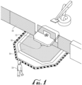
- FIG. 1 is a schematic representation of a laser scanner 10 employed in an example environment of use to protect against possible injury that may be caused if personnel nears the machine 12 without proper precaution.
- a fence 14 may not be feasible to protect against all possible injuries. Accordingly, other cautionary measures may need to be taken, such as using a safety laser scanner 10, to ensure that the area is properly monitored and is as safe as possible.
- FIG. 1 and the related written description is merely intended to provide an example environment of use and is not meant to be limiting. One having ordinary skill in the art will understand that the same principles may be applied to different environments without departing from the core of the disclosed subject matter.
- the laser scanner 10 may be arranged in any suitable position to form a light curtain for monitoring a zone 16 relative to the machine 12.
- the laser scanner 10 detects the presence of the person and takes suitable action, which may include sounding an alarm, deactivating the machine, and/or alerting appropriate personnel.
- the monitoring zone 16 may be initially configured for the laser scanner 10 to identify a target region surrounding the machine 12 that is under surveillance by the laser scanner 10.
- One example configuration method 100 is described below with collective reference to FIGS. 2-4 .
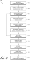
- FIG. 2 is a block diagram illustrating an example embodiment of a method 100 for configuring a laser scanner.
- the following proceeds with a description of the various steps in method 100. It should be understood that while the steps in the method are presented and described in a particular order, the order is for convenience only and is not meant to be limiting. In some embodiments, the steps may be performed in an order different than what is specified herein. In addition, the method may include additional steps and features other than those included herein. In some embodiments, the method may combine certain steps or omit certain steps altogether.
- the method 100 begins with initiating the laser scanner in a configuration mode.
- the configuration mode of the laser scanner is activated, such as by pressing a button on the laser scanner or by executing a command on a graphical user interface on a display of the laser scanner or on a remote device in communication with the laser scanner.
- the laser scanner is operable to capture the various vertex points/corners or other coordinate points that will comprise the edges of the monitoring zone once the method 100 is completed. Accordingly, the laser scanner is ready for input of a series of two-dimensional or three-dimensional points to define the area or volume to be monitored.
- the laser scanner samples the surrounding background area and stores the background field of view of the laser scanner.
- the background field of view may comprise the data relating to positions of various static objects located within the field of view of the laser scanner. These static objects may be walls, pillars, machinery, pieces of furniture, and so on.
- a background field of view of a laser scanner may present no static objects, if all such objects are out of the laser scanner field of view limits.
- the background field of view of the laser scanner stored during this step, may comprise various static items or may comprise no static items.
- the background field of view is recorded and stored for reference so as to avoid false alarms once the monitoring zone is set and/or to avoid a wrong processing and closure of the polygonal safety area after the vertex points have been acquired. After completion of steps 102 and 104, the monitoring zone is ready to be configured as described below.
- step 106 the operator enters or moves near the area to begin the process of defining the monitoring zone.
- the operator introduces a target item, which may be a handheld device or may be a part of the human body as further described below, into the field of view of the laser scanner and moves to a first vertex of the monitoring zone to be defined and stops.
- the laser scanner tracks a position of the operator and the target item as moving objects in the field of view.
- the operator sends a signal to the laser scanner via a remote controller to record the coordinate position of the first vertex point through the evaluation of the distance and the angular position of the operator with respect to the position of the safety laser scanner.
- the vertex point corresponds to the physical location of the user (and the target item) relative to the safety laser scanner.
- the remote controller may operate through one or more buttons, a touch screen, or a voice command, such as using a wireless microphone.
- the voice command may be given by the operator or other personnel working with the operator.
- the signal may be sent via a wireless remote control or mobile computer in communication with the laser scanner.
- the remote control may provide the signal to an external control unit, such as computer, industrial controller, master laser scanner in a master-slave configuration and so on, in communication with the laser scanner.
- the operator may place a known pattern or other object in the vertex point to be defined which can be identified by the laser scanner instead of positioning himself at the vertex point.
- the operator may hold a wireless remote controller and move to the first vertex point. Once at the first vertex point, the operator activates the wireless controller to communicate with the laser scanner and precisely define a coordinate position of the first vertex point.
- a remote wireless controller is that the operator is able to initiate communication with the laser scanner to define the vertex points as opposed to having the laser scanner search for the operator or for an object in the operator's possession. This method allows the operator more precise control and expedites the configuration process.
- Another advantage of using a wireless controller to communicate the vertex points from the operator to the laser scanner is that the operator has freedom of movement that is essentially unhindered.
- this method also permits the user to be static at the correct position, thereby ensuring that the vertex point is captured with a higher precision as compared to other solutions which may require additional movement by the operator.
- this method may provide a faster configuration process, since the user does not need to place a reference object at the various vertex points or activate the laser scanner each time the reference object is moved among the various vertex points. Accordingly, by being able to wirelessly signal when the vertex points have been acquired by the laser scanner, the shape of the monitoring zone may better reflect the natural movement of the operator relative to the dangerous machine so as to create an accurate monitoring zone that accounts for real-world use.
- the laser scanner determines whether the position of the signal is fixed (e.g., whether the operator is standing in a fixed position) to accurately obtain the vertex point.
- This step may be accomplished in any one of a variety of suitable means.
- the operator may transmit multiple signals with the wireless remote control in short succession, and the signals may be analyzed to determine whether the coordinate data is the same or overlaps for each signal.
- the laser scanner may also determine whether the operator is a moving object in its field of view at the time of receiving the signal.
- the laser scanner acquires or captures the vertex point based on the position of the operator (and the target item) as communicated via a signal from the remote control (or based on a reference object located at the vertex point).
- the laser scanner may communicate a signal to the operator indicating that the vertex point was acquired or obtained.
- the laser scanner may transmit a visible and/or audible signal that can be seen or heard by the operator.
- the laser scanner may illuminate an indicator on the remote control to confirm that the vertex point was successfully obtained.
- the operator may have the option to discard the acquired vertex point if a mistake was made, or if the vertex point needs to be repositioned.
- Methods steps 108 through 114 may be repeated a number of times (i.e., the operator and target item may move through a plurality of positions in the field of view) to identify additional vertex points for the monitoring zone in the same or similar fashion as described.
- the operator may transmit a signal to the laser scanner to identify the latest vertex point in the series as the last point.
- the laser scanner exits the configuration mode, as the configuration of the monitoring zone has been completed.
- the laser scanner aggregates all the positional coordinates for the respective vertex points and determines the monitoring zone for the laser scanner.
- the laser scanner further reviews the vertex points and monitoring zone to check the consistency and geometry of the monitoring zone. For most cases, as long as the boundaries of the vertex points do not overlap one another then the monitoring zone is acceptable.
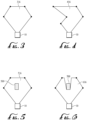
- FIG. 3 is a schematic illustration of a monitoring zone 316 having a generally polygon shape that forms an acceptable monitoring zone since none of the vertex points create overlapping sections for the laser scanner 10.
- FIG. 4 is a schematic illustration of a monitoring zone 416 that has an irregular shape, where the monitoring zone 416 has vertex points positioned to create overlapping regions that cannot be appropriately monitored by the laser scanner. Accordingly, the laser scanner would consider the monitoring zone illustrated in FIG. 3 as acceptable, while the monitoring zone in FIG. 4 is unacceptable and would require a reconfiguration.
- one or more static objects inside the background field of view of the laser scanner may be surrounded by vertex points. In such instances, the monitoring zone needs to account for the position of the static objects so that the zone is closed around the objects themselves. Additional information regarding this embodiment is described in further detail with reference to FIGS. 5 and 6 .
- FIGS. 5 and 6 collectively illustrate another embodiment of acceptable and unacceptable monitoring zones in the presence of a fixed obstacle 500.
- the acquired vertex points for the laser scanner 10 are set such that the compiled monitoring zone 516 encompasses the fixed object.
- the field-of-view of the laser scanner 10 is obscured by the fixed obstacle. Accordingly, the laser scanner 10 is unable to detect the presence of personnel within the monitoring zone 516, if the personnel happens to be adjacent or behind the fixed obstacle 500.
- FIG. 6 illustrates one embodiment of an acceptable monitoring zone 616 for handling the presence of fixed obstacles 500.
- the vertex points are set such that the fixed obstacle 500 remains outside of the monitoring zone 616, thereby allowing the laser scanner 10 to accurately monitoring all areas of the zone 616 without interference from the fixed obstacle 500.
- a second laser scanner (not shown) may be used to monitor the rear portion of the fixed obstacle 500, such that the two laser scanners together have complete coverage of the region, if desired.
- FIGS. 5-6 illustrate example embodiments of acceptable and unacceptable monitoring zones for handling the presence fixed obstacles.
- various other configurations for the monitoring zones may be made without departing from the principles of the disclosed subject matter.
- the laser scanner may display a graphical representation of the acquired monitoring zone to the operator for approval. If the displayed monitoring zone is accepted, then at step 122, the configuration mode is exited and the laser scanner is ready for deployment. If the displayed monitoring zone is rejected, then one or more of the vertex points may be discarded and the monitoring zone reconfigured until it is acceptable. In some embodiments, such as where a cluster of scanners is being configured (e.g., one master scanner and three slave scanners), the method 100 may be repeated multiple times to configure each of the slave scanners.
- the method may include the same or similar process as described in steps 102, 104, and 106.
- the operator can stand with his or her entire body in the monitoring zone (as described above with reference to method 100), where the laser scanner detects the body of the operator as the operator moves throughout the monitoring zone.
- the operator may instead enter the monitoring zone with only an arm or a hand instead of a body. This configuration approach may be useful when the monitoring zone includes a vertical area.
- Examples of vertical areas to be monitored may include doors or perimeter walls, through which an operator may not pass or access, as well as windows or openings in proximity to an operating machinery where the operator must not reach near or otherwise introduce part of his body.
- the configuration of the monitoring zone becomes highly intuitive because the operator merely needs to reach into the monitoring zone with a hand or arm to delineate the regions that need to be monitored by the laser scanner to ensure that personnel is alerted of possible dangers in those regions when the dangerous equipment is operating.
- the operator may signal the laser scanner to obtain and store that point. Once all points have been marked and stored by the laser scanner, then the operator may provide a signal to the laser scanner to exit the configuration mode in a similar fashion as described above. Thereafter, the appropriate polygonal monitoring zone may be created in a similar fashion as described previously.
- the process of capturing vertex points for ultimately configuring the target monitoring zone described in steps 108, 110, 112, and 114 may be a more dynamic process.
- an operator may approach the laser scanner and in a process similar to step 110, the operator may signal to the laser scanner (e.g., such as via a wireless remote) that the operator has reached the first vertex point for commencing the process of configuring the monitoring zone.
- the operator may mark the boundaries of the monitoring zone simply by walking or moving. In some embodiments, the boundaries may be marked by sending signals via a wireless remote control while walking.
- the boundaries of the monitoring zone may be marked without requiring the operator to send any further signals to the laser scanner to mark individual vertex points.
- the laser scanner tracks the continuous movement of the user and evaluates the distance and angular position of the user. As the user moves, the laser scanner monitors the user's movements and, in this fashion, acquires a relatively large number of contour points, each of the points being additional positional coordinates for a plurality of respective vertex points.
- the contour points may be automatically acquired at predetermined time intervals based on the plurality of positions of the target item and independent of further activation of the remote controller.
- the operator may use the remote controller to send a second signal to the laser scanner that the configuration process is complete. Thereafter, the laser scanner compiles all the contour points and configures the monitoring zone for approval by the operator in the same or similar fashion as described previously with reference to the method 100.
Landscapes
- Physics & Mathematics (AREA)
- General Physics & Mathematics (AREA)
- Engineering & Computer Science (AREA)
- Computer Networks & Wireless Communication (AREA)
- Radar, Positioning & Navigation (AREA)
- Remote Sensing (AREA)
- Electromagnetism (AREA)
- Emergency Management (AREA)
- Business, Economics & Management (AREA)
- Life Sciences & Earth Sciences (AREA)
- General Life Sciences & Earth Sciences (AREA)
- Geophysics (AREA)
- Optical Radar Systems And Details Thereof (AREA)
- Emergency Alarm Devices (AREA)
Description
- The present disclosure relates generally to systems and methods for configuring laser scanners, and in particular, to such systems and methods for facilitating the configuration process and defining a safety or monitoring region of the laser scanner.
- Generally speaking, a conventional safety laser scanner includes a plurality of light beams generated by one or more light transmitters. In some scanners, the light beams may be stacked or arranged in such a way to direct light along a vertical or horizontal plane to create a light curtain. When a person or object interrupts the light beam or light curtain, such as by walking through or extending a limb into the path of light, the laser scanner detects the disruption. Upon detecting the disruption, the laser scanner may in turn sound an alarm or send a signal to a remote computer to alert someone of the disturbance.
- Such laser scanners may be used in a variety of situations. For example, laser scanners may be used to protect valuable items, such as artwork, vaults, and safes, to protect against entry into private buildings or secure areas, or to control and monitor access to work spaces where dangerous machines may be in operation. In any of these or other similar situations, the scanners may be used to monitor the protected area and raise an alarm when someone enters.
- Typically, to employ such laser scanners, a target monitoring zone of the laser scanner is first configured. Many conventional methods have been used to configure this monitoring zone, however, these methods are typically complex and require trained personnel and/or specialized equipment. For example, one method involves using a graphical user interface and a computer using specialized software to program the coordinates of the monitoring zone to configure the laser scanner. Other solutions involve directly inputting coordinate information into the laser scanner, however, such methods are useful only for defining very simply geometry (such as square or rectangular zones) and still require trained personnel to execute and equipment to accurate identify the coordinate information. Furthermore, for laser scanners that are fixed at locations that are difficult to reach (e.g., on high ceilings or walls), this method may be impractical.
US 2015/212202 A1 discloses a method and a system for configuring a laser scanner according to the preamble of independent claims 1 and 8, respectively. Further methods and systems for configuring a laser scanner are disclosed inUS 2016/040827 A1 andUS 8 933 593 B2 . - Accordingly, the present inventor has determined that it would be desirable to have an improved and simplified method of configuring a monitoring zone for a laser scanner that does not require the use of complex software or skilled technicians. In addition, the present inventor has identified a need for such a configuring method that may be easily and quickly completed by an ordinary person without the need for specialized training. Additional aspects and advantages of such systems will be apparent from the following detailed description of example embodiments, which proceed with reference to the accompanying drawings.
- Understanding that the drawings depict only certain embodiments and are not, therefore, to be considered limiting in nature, these embodiments will be described and explained with additional specificity and detail with reference to the drawings.
-
-
FIG. 1 is a schematic illustration of a laser scanner in an example environment of use in accordance with one embodiment. -
FIG. 2 is a block diagram illustrating an example method for configuring a laser scanner in accordance with one embodiment. -
FIG. 3 is a schematic drawing of an acceptable monitoring zone of the laser scanner in accordance with one embodiment. -
FIG. 4 is a schematic drawing of an unacceptable monitoring zone of the laser scanner in accordance with one embodiment. -
FIG. 5 is a schematic drawing of an unacceptable monitoring zone of the laser scanner in accordance with one embodiment including the presence of a fixed obstacle. -
FIG. 6 is a schematic drawing of an acceptable monitoring zone of the laser scanner in accordance with one embodiment including the presence of a fixed obstacle. - With reference to the drawings, this section describes particular embodiments and their detailed construction and operation. The embodiments described herein are set forth by way of illustration only and not limitation.
- In the following description of the figures and any example embodiments, certain embodiments may describe use of the laser scanner to monitor safety areas surrounding a machine to protect personnel and reduce the likelihood of inadvertent injuries when using large or dangerous machines. It should be understood that these examples are merely example uses for the described system and should not be considered as limiting. In other embodiments, the laser scanner may be used for any one of a variety of purposes, such as for monitoring access to secure areas, protecting valuables, or any other suitable purpose.
-
FIGS. 1-6 collectively illustrate details relating to a method for configuring a monitoring zone for a laser scanner. As briefly mentioned previously, graphical user interfaces combined with computer technology have been used in previous systems to configure the monitoring zones. One disadvantage of such systems is that using the graphical user interface and computers require specialized skills for appropriate configuration. Typically, configuring the monitoring zones is the most time-consuming activity in the configuration process of a safety laser scanner system. Accordingly, simplifying the configuration process not only eliminates a need for having trained personnel to configure the laser scanner, but it also reduces the overall configuration time for the laser scanner system. Moreover, a simplified configuration process also allows for easy configuration when more than a single area needs to be configured, such as for systems using a cluster of scanners to monitor multiple zones. - As is further described in detail below, the disclosed subject matter relates to a simplified method for configuring the monitoring zone of the laser scanner so as to avoid conventional configuration methods that rely heavily on the use of complex graphical user interfaces and expensive equipment. Rather, the disclosed method provides simple and user friendly steps to configure the monitoring zone of the laser scanner with relative ease. Additional details and information of these embodiments is further described below with specific reference to the figures.
-
FIG. 1 is a schematic representation of alaser scanner 10 employed in an example environment of use to protect against possible injury that may be caused if personnel nears themachine 12 without proper precaution. As illustrated inFIG. 1 , much of the danger that may be caused by the machine can be avoided by restricting access to themachine 12 itself and its surrounding area, such as by thefence 14 or by use of other physical barriers. However, for some machines or environments, afence 14 may not be feasible to protect against all possible injuries. Accordingly, other cautionary measures may need to be taken, such as using asafety laser scanner 10, to ensure that the area is properly monitored and is as safe as possible. As mentioned previously,FIG. 1 and the related written description is merely intended to provide an example environment of use and is not meant to be limiting. One having ordinary skill in the art will understand that the same principles may be applied to different environments without departing from the core of the disclosed subject matter. - With reference to
FIG. 1 , thelaser scanner 10 may be arranged in any suitable position to form a light curtain for monitoring azone 16 relative to themachine 12. Whenpersonnel 18 nears themachine 12 and enters thezone 16, the light curtain is disrupted. At this point, thelaser scanner 10 detects the presence of the person and takes suitable action, which may include sounding an alarm, deactivating the machine, and/or alerting appropriate personnel. As mentioned previously, themonitoring zone 16 may be initially configured for thelaser scanner 10 to identify a target region surrounding themachine 12 that is under surveillance by thelaser scanner 10. Oneexample configuration method 100 is described below with collective reference toFIGS. 2-4 . -
FIG. 2 is a block diagram illustrating an example embodiment of amethod 100 for configuring a laser scanner. The following proceeds with a description of the various steps inmethod 100. It should be understood that while the steps in the method are presented and described in a particular order, the order is for convenience only and is not meant to be limiting. In some embodiments, the steps may be performed in an order different than what is specified herein. In addition, the method may include additional steps and features other than those included herein. In some embodiments, the method may combine certain steps or omit certain steps altogether. - The
method 100 begins with initiating the laser scanner in a configuration mode. Atstep 102, the configuration mode of the laser scanner is activated, such as by pressing a button on the laser scanner or by executing a command on a graphical user interface on a display of the laser scanner or on a remote device in communication with the laser scanner. In the configuration mode, the laser scanner is operable to capture the various vertex points/corners or other coordinate points that will comprise the edges of the monitoring zone once themethod 100 is completed. Accordingly, the laser scanner is ready for input of a series of two-dimensional or three-dimensional points to define the area or volume to be monitored. Atstep 104, the laser scanner samples the surrounding background area and stores the background field of view of the laser scanner. In some embodiments, the background field of view may comprise the data relating to positions of various static objects located within the field of view of the laser scanner. These static objects may be walls, pillars, machinery, pieces of furniture, and so on. In a particular case, a background field of view of a laser scanner may present no static objects, if all such objects are out of the laser scanner field of view limits. Accordingly, the background field of view of the laser scanner, stored during this step, may comprise various static items or may comprise no static items. The background field of view is recorded and stored for reference so as to avoid false alarms once the monitoring zone is set and/or to avoid a wrong processing and closure of the polygonal safety area after the vertex points have been acquired. After completion ofsteps - In
step 106, the operator enters or moves near the area to begin the process of defining the monitoring zone. Atstep 108, the operator introduces a target item, which may be a handheld device or may be a part of the human body as further described below, into the field of view of the laser scanner and moves to a first vertex of the monitoring zone to be defined and stops. As the operator enters, the laser scanner tracks a position of the operator and the target item as moving objects in the field of view. Atstep 110, once the operator has reached the first vertex point, the operator sends a signal to the laser scanner via a remote controller to record the coordinate position of the first vertex point through the evaluation of the distance and the angular position of the operator with respect to the position of the safety laser scanner. In other words, the vertex point corresponds to the physical location of the user (and the target item) relative to the safety laser scanner. The remote controller may operate through one or more buttons, a touch screen, or a voice command, such as using a wireless microphone. The voice command may be given by the operator or other personnel working with the operator. In some embodiments, the signal may be sent via a wireless remote control or mobile computer in communication with the laser scanner. In some embodiments, the remote control may provide the signal to an external control unit, such as computer, industrial controller, master laser scanner in a master-slave configuration and so on, in communication with the laser scanner. In other embodiments, the operator may place a known pattern or other object in the vertex point to be defined which can be identified by the laser scanner instead of positioning himself at the vertex point. - In one embodiment, the operator may hold a wireless remote controller and move to the first vertex point. Once at the first vertex point, the operator activates the wireless controller to communicate with the laser scanner and precisely define a coordinate position of the first vertex point. One advantage of using a remote wireless controller is that the operator is able to initiate communication with the laser scanner to define the vertex points as opposed to having the laser scanner search for the operator or for an object in the operator's possession. This method allows the operator more precise control and expedites the configuration process. Another advantage of using a wireless controller to communicate the vertex points from the operator to the laser scanner is that the operator has freedom of movement that is essentially unhindered. Moreover, this method also permits the user to be static at the correct position, thereby ensuring that the vertex point is captured with a higher precision as compared to other solutions which may require additional movement by the operator. In addition, this method may provide a faster configuration process, since the user does not need to place a reference object at the various vertex points or activate the laser scanner each time the reference object is moved among the various vertex points. Accordingly, by being able to wirelessly signal when the vertex points have been acquired by the laser scanner, the shape of the monitoring zone may better reflect the natural movement of the operator relative to the dangerous machine so as to create an accurate monitoring zone that accounts for real-world use.
- Once the laser scanner receives the signal, at
step 112, the laser scanner determines whether the position of the signal is fixed (e.g., whether the operator is standing in a fixed position) to accurately obtain the vertex point. This step may be accomplished in any one of a variety of suitable means. For example, in some embodiments, the operator may transmit multiple signals with the wireless remote control in short succession, and the signals may be analyzed to determine whether the coordinate data is the same or overlaps for each signal. In other embodiments, once the laser scanner receives the signal, it may also determine whether the operator is a moving object in its field of view at the time of receiving the signal. - At
step 114, the laser scanner acquires or captures the vertex point based on the position of the operator (and the target item) as communicated via a signal from the remote control (or based on a reference object located at the vertex point). The laser scanner may communicate a signal to the operator indicating that the vertex point was acquired or obtained. For example, in some embodiments, the laser scanner may transmit a visible and/or audible signal that can be seen or heard by the operator. In other embodiments, the laser scanner may illuminate an indicator on the remote control to confirm that the vertex point was successfully obtained. In some embodiments, the operator may have the option to discard the acquired vertex point if a mistake was made, or if the vertex point needs to be repositioned. Methods steps 108 through 114 may be repeated a number of times (i.e., the operator and target item may move through a plurality of positions in the field of view) to identify additional vertex points for the monitoring zone in the same or similar fashion as described. - Once all vertex points have been identified and acquired by the laser scanner, at
step 116, the operator may transmit a signal to the laser scanner to identify the latest vertex point in the series as the last point. At this point, the laser scanner exits the configuration mode, as the configuration of the monitoring zone has been completed. After input of all the vertex points, atstep 118, the laser scanner aggregates all the positional coordinates for the respective vertex points and determines the monitoring zone for the laser scanner. The laser scanner further reviews the vertex points and monitoring zone to check the consistency and geometry of the monitoring zone. For most cases, as long as the boundaries of the vertex points do not overlap one another then the monitoring zone is acceptable. - For example,
FIG. 3 is a schematic illustration of amonitoring zone 316 having a generally polygon shape that forms an acceptable monitoring zone since none of the vertex points create overlapping sections for thelaser scanner 10.FIG. 4 is a schematic illustration of amonitoring zone 416 that has an irregular shape, where themonitoring zone 416 has vertex points positioned to create overlapping regions that cannot be appropriately monitored by the laser scanner. Accordingly, the laser scanner would consider the monitoring zone illustrated inFIG. 3 as acceptable, while the monitoring zone inFIG. 4 is unacceptable and would require a reconfiguration. In some embodiments, one or more static objects inside the background field of view of the laser scanner may be surrounded by vertex points. In such instances, the monitoring zone needs to account for the position of the static objects so that the zone is closed around the objects themselves. Additional information regarding this embodiment is described in further detail with reference toFIGS. 5 and 6 . -
FIGS. 5 and 6 collectively illustrate another embodiment of acceptable and unacceptable monitoring zones in the presence of a fixedobstacle 500. For example, with reference toFIG. 5 , the acquired vertex points for thelaser scanner 10 are set such that the compiledmonitoring zone 516 encompasses the fixed object. One issue with this configuration for themonitoring zone 516 is that the field-of-view of thelaser scanner 10 is obscured by the fixed obstacle. Accordingly, thelaser scanner 10 is unable to detect the presence of personnel within themonitoring zone 516, if the personnel happens to be adjacent or behind the fixedobstacle 500. -
FIG. 6 illustrates one embodiment of anacceptable monitoring zone 616 for handling the presence of fixedobstacles 500. With reference toFIG. 6 , the vertex points are set such that the fixedobstacle 500 remains outside of themonitoring zone 616, thereby allowing thelaser scanner 10 to accurately monitoring all areas of thezone 616 without interference from the fixedobstacle 500. In some embodiments, a second laser scanner (not shown) may be used to monitor the rear portion of the fixedobstacle 500, such that the two laser scanners together have complete coverage of the region, if desired. - It should be understood that
FIGS. 5-6 illustrate example embodiments of acceptable and unacceptable monitoring zones for handling the presence fixed obstacles. In other embodiments, various other configurations for the monitoring zones may be made without departing from the principles of the disclosed subject matter. - Once the acquired monitoring zone has been completed and is evaluated as being acceptable, at
step 120, the laser scanner may display a graphical representation of the acquired monitoring zone to the operator for approval. If the displayed monitoring zone is accepted, then atstep 122, the configuration mode is exited and the laser scanner is ready for deployment. If the displayed monitoring zone is rejected, then one or more of the vertex points may be discarded and the monitoring zone reconfigured until it is acceptable. In some embodiments, such as where a cluster of scanners is being configured (e.g., one master scanner and three slave scanners), themethod 100 may be repeated multiple times to configure each of the slave scanners. - In some embodiments, certain of the method steps described above may be altered, varied, and/or omitted without departing from the principles of the disclosed subject matter. For example, in one embodiment, the method may include the same or similar process as described in
steps step 108, depending on the detection capabilities of the laser scanner, the operator can stand with his or her entire body in the monitoring zone (as described above with reference to method 100), where the laser scanner detects the body of the operator as the operator moves throughout the monitoring zone. However, in other embodiments, the operator may instead enter the monitoring zone with only an arm or a hand instead of a body. This configuration approach may be useful when the monitoring zone includes a vertical area. Examples of vertical areas to be monitored may include doors or perimeter walls, through which an operator may not pass or access, as well as windows or openings in proximity to an operating machinery where the operator must not reach near or otherwise introduce part of his body. In such embodiments, the configuration of the monitoring zone becomes highly intuitive because the operator merely needs to reach into the monitoring zone with a hand or arm to delineate the regions that need to be monitored by the laser scanner to ensure that personnel is alerted of possible dangers in those regions when the dangerous equipment is operating. Once the hand or arm is at a distance that the operator determines is an acceptable border of the monitoring zone, the operator may signal the laser scanner to obtain and store that point. Once all points have been marked and stored by the laser scanner, then the operator may provide a signal to the laser scanner to exit the configuration mode in a similar fashion as described above. Thereafter, the appropriate polygonal monitoring zone may be created in a similar fashion as described previously. - In another embodiment, the process of capturing vertex points for ultimately configuring the target monitoring zone described in
steps method 100.
Claims (15)
- A method of configuring a laser scanner (10), the method comprising:activating (102) a configuration mode of the laser scanner;sampling (104) a field of view of the laser scanner;storing (104) a background field of view of the laser scanner;introducing (108) a target item in the field of view of the laser scanner;acquiring (114), via the laser scanner, a position of the target item as a vertex point of a monitoring zone (16) to be configured;moving (108) the target item through a plurality of positions in the field of view of the laser scanner;acquiring (114), via the laser scanner, a positional coordinate for each of a plurality of vertex points corresponding to the plurality of positions of the target item; andaggregating (118) the positional coordinates for the respective vertex points to determine the monitoring zone for the laser scanner, characterized by further comprisingreceiving (110) at the laser scanner, a signal from a remote controller, and in thatsaid acquiring (114), via the laser scanner, a position of the target item as a vertex point of a monitoring zone (16) to be configured is based on the signal received from the remote controller.
- The method of claim 1, where the target item is held by a person entering the field of view of the laser scanner or is part of a human body or a human body entering in the field of view of the laser scanner.
- The method of claim 1 or 2, further comprising displaying (120), via the laser scanner, a graphical representation of the monitoring zone for the laser scanner.
- The method of any of claims 1-3, further comprising:analyzing (118) the positional coordinates for the respective vertex points; anddetermining (118) whether the monitoring zone (16) can be properly monitored by the laser scanner and, accordingly, considered as acceptable based on the positional coordinates of the vertex points.
- The method of any of claims 1-4, further comprising generating a second signal, via the laser scanner, after acquiring the positional coordinate for each of the plurality of vertex points, the second signal indicating a successful acquisition of the positional coordinate, wherein preferably the second signal is an acoustic signal or a visual signal.
- The method of any of claims 1-5, further comprising:activating (110) the remote controller to transmit the signal to the laser scanner at an initial vertex point;acquiring (114), via the laser scanner, the positional coordinate of the initial vertex point;acquiring (114), via the laser scanner, additional positional coordinates for a plurality of respective vertex points at predetermined time intervals based on the plurality of positions of the target item and independent of further activation of the remote controller; andactivating (116) the remote controller to transmit a second signal to the laser scanner at a final vertex point.
- The method of any of claims 1-5, further comprising:activating (110) the remote controller to transmit the signal to the laser scanner at an initial vertex point;acquiring (114), via the laser scanner, the positional coordinate of the initial vertex point; andacquiring (114), via the laser scanner, additional positional coordinates for a plurality of respective vertex points based on a signal received from the remote controller at each of the plurality of positions of the target item.
- A scanning system comprising:a scanner (10) having a field of view, the scanner further including a configuration mode for configuring a monitoring zone of the scanner; and
the scanner acquiring (114) a positional coordinate of a target item as a vertex point of the monitoring zone (16) within the field of view of the laser scanner,wherein the laser scanner is operable to acquire (114) a plurality of vertex points within the field of view of the laser scanner, each vertex point corresponding to one of a plurality of positions of the target object in the field of view, and aggregate (118) the positional coordinates of the respective plurality of vertex points to determine the monitoring zone for the scanner,characterized by further comprisinga remote controller in communication with the scanner, the remote controller operable to transmit a signal to the scanner, wherein the scanner acquires (114) said positional coordinate of a target item as vertex point of the monitoring zone (16) within the field of view of the laser scanner when the signal is received by the scanner, and in thatthe laser scanner is operable to acquire (114) the plurality of vertex points based on at least a signal from the remote controller. - The system of claim 8, where the target item is configured to be held by a person (18) entering the field of view of the laser scanner or is part of a human body or a human body entering in the field of view of the laser scanner.
- The system of claim 8 or 9, further comprising a display in operable communication with the laser scanner, wherein the display is operable to present (120) a graphical representation of the monitoring zone (16) for the laser scanner.
- The system of any of claims 8-10, wherein the laser scanner is further operable to analyze (118) the positional coordinates for each of the vertex points and determine (118) whether the monitoring zone (16) can be properly monitored by the laser scanner and, accordingly, considered as acceptable based on the positional coordinates of the vertex points
- The system of any of claims 8-11, wherein the laser scanner is further operable to generate a second signal after acquiring the positional coordinate for each of the plurality of vertex points, the second signal indicating a successful acquisition of the positional coordinate, and wherein preferably the second signal is an acoustic signal or a visual signal.
- The system of any of claims 8-12, wherein the laser scanner is configured to monitor continuous movement of the target item to acquire one or more of the plurality of positional coordinates.
- The system of any of claims 8-13, wherein the remote controller is operable to transmit (110) the signal to the laser scanner at an initial vertex point, and wherein the laser scanner is further operable to acquire (114) the positional coordinate of the initial vertex point, and to further acquire (114) additional positional coordinates for a plurality of respective vertex points at predetermined time intervals based on the position of the target item and independent of further activation of the remote controller.
- The system of any of claims 8-12, wherein the remote controller is operable to transmit (110) the signal to the laser scanner at an initial vertex point, and wherein the laser scanner is further operable to acquire (114) the positional coordinate of the initial vertex point, and to further acquire (114) additional positional coordinates for a plurality of respective vertex points based on a signal received from the remote controller at each of the plurality of positions of the target item.
Applications Claiming Priority (1)
| Application Number | Priority Date | Filing Date | Title |
|---|---|---|---|
| US15/957,709 US10698132B2 (en) | 2018-04-19 | 2018-04-19 | System and method for configuring safety laser scanners with a defined monitoring zone |
Publications (2)
| Publication Number | Publication Date |
|---|---|
| EP3557282A1 EP3557282A1 (en) | 2019-10-23 |
| EP3557282B1 true EP3557282B1 (en) | 2024-09-18 |
Family
ID=66439844
Family Applications (1)
| Application Number | Title | Priority Date | Filing Date |
|---|---|---|---|
| EP19169422.3A Active EP3557282B1 (en) | 2018-04-19 | 2019-04-16 | System and method for configuring safety laser scanners |
Country Status (2)
| Country | Link |
|---|---|
| US (1) | US10698132B2 (en) |
| EP (1) | EP3557282B1 (en) |
Families Citing this family (3)
| Publication number | Priority date | Publication date | Assignee | Title |
|---|---|---|---|---|
| CN110908003A (en) * | 2019-12-03 | 2020-03-24 | 中车南京浦镇车辆有限公司 | Active barrier detection system based on unmanned driving |
| US12266247B1 (en) | 2023-09-28 | 2025-04-01 | Tauseef Mohammad Kazi | System for detecting and alerting intrusion into a protected area with a mechanism to decipher between authorized and unauthorized access |
| WO2025069395A1 (en) * | 2023-09-29 | 2025-04-03 | 株式会社Fuji | Sensor system |
Citations (8)
| Publication number | Priority date | Publication date | Assignee | Title |
|---|---|---|---|---|
| EP0967492A1 (en) | 1998-06-24 | 1999-12-29 | Schmersal-EOT GmbH & Co. KG | Method for opto-electronic surveillance of a guard area |
| EP2048557A1 (en) | 2007-10-11 | 2009-04-15 | Sick Ag | Optoelectronic sensor and mobile device and configuration method |
| EP2682780A1 (en) | 2012-07-04 | 2014-01-08 | Sick Ag | Method for securely detecting and positioning objects and safety device |
| EP2790040A1 (en) | 2013-04-08 | 2014-10-15 | Sick Ag | System and method for configuring a surveillance area of an optoelectronic monitoring device |
| US8933593B2 (en) | 2010-05-04 | 2015-01-13 | Sick Ag | Distance measuring optoelectronic safety sensor and method of monitoring a monitored zone |
| EP2899566A1 (en) | 2014-01-24 | 2015-07-29 | Sick Ag | Method for configuring a laser scanner and configuration object for the same |
| US20160040827A1 (en) | 2013-04-26 | 2016-02-11 | Pilz Gmbh & Co. Kg | Apparatus and method for safeguarding an automatically operating machine |
| US20170242099A1 (en) | 2016-02-22 | 2017-08-24 | Keyence Corporation | Safety Scanner And Optical Safety System |
Family Cites Families (7)
| Publication number | Priority date | Publication date | Assignee | Title |
|---|---|---|---|---|
| US5455669A (en) | 1992-12-08 | 1995-10-03 | Erwin Sick Gmbh Optik-Elektronik | Laser range finding apparatus |
| US8018579B1 (en) | 2005-10-21 | 2011-09-13 | Apple Inc. | Three-dimensional imaging and display system |
| US8320621B2 (en) | 2009-12-21 | 2012-11-27 | Microsoft Corporation | Depth projector system with integrated VCSEL array |
| US20110267262A1 (en) | 2010-04-30 | 2011-11-03 | Jacques Gollier | Laser Scanning Projector Device for Interactive Screen Applications |
| US20120062867A1 (en) | 2010-09-10 | 2012-03-15 | Kazuhiro Shibatani | Laser distance measurement apparatus |
| JP5748521B2 (en) | 2011-03-29 | 2015-07-15 | 株式会社トプコン | Laser scanner and moving object detection method |
| EP2518709B1 (en) | 2011-04-28 | 2013-06-12 | Sick Ag | Anti-theft device and method for detecting unauthorised access and entry |
-
2018
- 2018-04-19 US US15/957,709 patent/US10698132B2/en active Active
-
2019
- 2019-04-16 EP EP19169422.3A patent/EP3557282B1/en active Active
Patent Citations (9)
| Publication number | Priority date | Publication date | Assignee | Title |
|---|---|---|---|---|
| EP0967492A1 (en) | 1998-06-24 | 1999-12-29 | Schmersal-EOT GmbH & Co. KG | Method for opto-electronic surveillance of a guard area |
| EP2048557A1 (en) | 2007-10-11 | 2009-04-15 | Sick Ag | Optoelectronic sensor and mobile device and configuration method |
| US8933593B2 (en) | 2010-05-04 | 2015-01-13 | Sick Ag | Distance measuring optoelectronic safety sensor and method of monitoring a monitored zone |
| EP2682780A1 (en) | 2012-07-04 | 2014-01-08 | Sick Ag | Method for securely detecting and positioning objects and safety device |
| EP2790040A1 (en) | 2013-04-08 | 2014-10-15 | Sick Ag | System and method for configuring a surveillance area of an optoelectronic monitoring device |
| US20160040827A1 (en) | 2013-04-26 | 2016-02-11 | Pilz Gmbh & Co. Kg | Apparatus and method for safeguarding an automatically operating machine |
| EP2899566A1 (en) | 2014-01-24 | 2015-07-29 | Sick Ag | Method for configuring a laser scanner and configuration object for the same |
| US20150212202A1 (en) | 2014-01-24 | 2015-07-30 | Sick Ag | Method of configuring a laser scanner and configuration object therefore |
| US20170242099A1 (en) | 2016-02-22 | 2017-08-24 | Keyence Corporation | Safety Scanner And Optical Safety System |
Also Published As
| Publication number | Publication date |
|---|---|
| US20190324169A1 (en) | 2019-10-24 |
| EP3557282A1 (en) | 2019-10-23 |
| US10698132B2 (en) | 2020-06-30 |
Similar Documents
| Publication | Publication Date | Title |
|---|---|---|
| US20220220697A1 (en) | Object detection system and method | |
| EP3557282B1 (en) | System and method for configuring safety laser scanners | |
| CN111226178B (en) | Surveillance equipment, industrial systems, methods and computer programs for surveillance | |
| JP6601155B2 (en) | Robot control system | |
| JP6822069B2 (en) | Monitoring system, monitoring device, and monitoring method | |
| EP3186985B1 (en) | A computerised tracking and proximity warning method and system for personnel, plant and equipment operating both above and below the ground or their movement therebetween | |
| EP3363602B1 (en) | Monitoring system, monitoring device, and monitoring method | |
| KR20180037209A (en) | Automation systems and processes to provide personal safety | |
| CA2928174C (en) | Systems and methods for automated device pairing | |
| KR20200054324A (en) | Calibration of sensor systems including multiple mobile sensors | |
| CN102483846B (en) | Method and apparatus for monitoring a spatial region | |
| CN107072611B (en) | Protection system for protecting a person against X-ray scatter radiation | |
| JP5964636B2 (en) | Intrusion monitoring device | |
| JP6045806B2 (en) | Intrusion monitoring device | |
| EP2899566B1 (en) | Method for configuring a laser scanner and configuration object for the same | |
| WO2020186051A1 (en) | Systems, apparatus and methods for properly locating items | |
| JP2020163492A (en) | Operating area limiting method, robot control device, and alarm | |
| CN119580467A (en) | Lifting operation safety warning method, device, storage medium and electronic equipment | |
| JP2022064653A (en) | Monitoring control device and monitoring control program | |
| JP7702682B2 (en) | Monitoring device, setting support device, area setting method, and setting support method | |
| CN115421475A (en) | Area setting device, rack, control system, area setting method, and recording medium storing program | |
| JP6367100B2 (en) | Area monitoring sensor | |
| KR101952596B1 (en) | heavy equipment system for Saving Life of Buried Person having active RFID tag | |
| KR101387028B1 (en) | Location system of monitoring needle position for removal needle | |
| JP2023074350A (en) | Scanner device and area setting method |
Legal Events
| Date | Code | Title | Description |
|---|---|---|---|
| PUAI | Public reference made under article 153(3) epc to a published international application that has entered the european phase |
Free format text: ORIGINAL CODE: 0009012 |
|
| STAA | Information on the status of an ep patent application or granted ep patent |
Free format text: STATUS: THE APPLICATION HAS BEEN PUBLISHED |
|
| AK | Designated contracting states |
Kind code of ref document: A1 Designated state(s): AL AT BE BG CH CY CZ DE DK EE ES FI FR GB GR HR HU IE IS IT LI LT LU LV MC MK MT NL NO PL PT RO RS SE SI SK SM TR |
|
| AX | Request for extension of the european patent |
Extension state: BA ME |
|
| STAA | Information on the status of an ep patent application or granted ep patent |
Free format text: STATUS: REQUEST FOR EXAMINATION WAS MADE |
|
| 17P | Request for examination filed |
Effective date: 20200327 |
|
| RBV | Designated contracting states (corrected) |
Designated state(s): AL AT BE BG CH CY CZ DE DK EE ES FI FR GB GR HR HU IE IS IT LI LT LU LV MC MK MT NL NO PL PT RO RS SE SI SK SM TR |
|
| STAA | Information on the status of an ep patent application or granted ep patent |
Free format text: STATUS: EXAMINATION IS IN PROGRESS |
|
| 17Q | First examination report despatched |
Effective date: 20201211 |
|
| P01 | Opt-out of the competence of the unified patent court (upc) registered |
Effective date: 20230525 |
|
| GRAP | Despatch of communication of intention to grant a patent |
Free format text: ORIGINAL CODE: EPIDOSNIGR1 |
|
| STAA | Information on the status of an ep patent application or granted ep patent |
Free format text: STATUS: GRANT OF PATENT IS INTENDED |
|
| INTG | Intention to grant announced |
Effective date: 20240426 |
|
| GRAS | Grant fee paid |
Free format text: ORIGINAL CODE: EPIDOSNIGR3 |
|
| GRAA | (expected) grant |
Free format text: ORIGINAL CODE: 0009210 |
|
| STAA | Information on the status of an ep patent application or granted ep patent |
Free format text: STATUS: THE PATENT HAS BEEN GRANTED |
|
| AK | Designated contracting states |
Kind code of ref document: B1 Designated state(s): AL AT BE BG CH CY CZ DE DK EE ES FI FR GB GR HR HU IE IS IT LI LT LU LV MC MK MT NL NO PL PT RO RS SE SI SK SM TR |
|
| REG | Reference to a national code |
Ref country code: GB Ref legal event code: FG4D |
|
| REG | Reference to a national code |
Ref country code: CH Ref legal event code: EP |
|
| REG | Reference to a national code |
Ref country code: IE Ref legal event code: FG4D |
|
| REG | Reference to a national code |
Ref country code: DE Ref legal event code: R096 Ref document number: 602019058995 Country of ref document: DE |
|
| REG | Reference to a national code |
Ref country code: LT Ref legal event code: MG9D |
|
| PG25 | Lapsed in a contracting state [announced via postgrant information from national office to epo] |
Ref country code: NO Free format text: LAPSE BECAUSE OF FAILURE TO SUBMIT A TRANSLATION OF THE DESCRIPTION OR TO PAY THE FEE WITHIN THE PRESCRIBED TIME-LIMIT Effective date: 20241218 |
|
| PG25 | Lapsed in a contracting state [announced via postgrant information from national office to epo] |
Ref country code: GR Free format text: LAPSE BECAUSE OF FAILURE TO SUBMIT A TRANSLATION OF THE DESCRIPTION OR TO PAY THE FEE WITHIN THE PRESCRIBED TIME-LIMIT Effective date: 20241219 Ref country code: FI Free format text: LAPSE BECAUSE OF FAILURE TO SUBMIT A TRANSLATION OF THE DESCRIPTION OR TO PAY THE FEE WITHIN THE PRESCRIBED TIME-LIMIT Effective date: 20240918 |
|
| PG25 | Lapsed in a contracting state [announced via postgrant information from national office to epo] |
Ref country code: BG Free format text: LAPSE BECAUSE OF FAILURE TO SUBMIT A TRANSLATION OF THE DESCRIPTION OR TO PAY THE FEE WITHIN THE PRESCRIBED TIME-LIMIT Effective date: 20240918 |
|
| PG25 | Lapsed in a contracting state [announced via postgrant information from national office to epo] |
Ref country code: LV Free format text: LAPSE BECAUSE OF FAILURE TO SUBMIT A TRANSLATION OF THE DESCRIPTION OR TO PAY THE FEE WITHIN THE PRESCRIBED TIME-LIMIT Effective date: 20240918 |
|
| PG25 | Lapsed in a contracting state [announced via postgrant information from national office to epo] |
Ref country code: HR Free format text: LAPSE BECAUSE OF FAILURE TO SUBMIT A TRANSLATION OF THE DESCRIPTION OR TO PAY THE FEE WITHIN THE PRESCRIBED TIME-LIMIT Effective date: 20240918 |
|
| REG | Reference to a national code |
Ref country code: NL Ref legal event code: MP Effective date: 20240918 |
|
| PG25 | Lapsed in a contracting state [announced via postgrant information from national office to epo] |
Ref country code: RS Free format text: LAPSE BECAUSE OF FAILURE TO SUBMIT A TRANSLATION OF THE DESCRIPTION OR TO PAY THE FEE WITHIN THE PRESCRIBED TIME-LIMIT Effective date: 20241218 |
|
| PG25 | Lapsed in a contracting state [announced via postgrant information from national office to epo] |
Ref country code: RS Free format text: LAPSE BECAUSE OF FAILURE TO SUBMIT A TRANSLATION OF THE DESCRIPTION OR TO PAY THE FEE WITHIN THE PRESCRIBED TIME-LIMIT Effective date: 20241218 Ref country code: NO Free format text: LAPSE BECAUSE OF FAILURE TO SUBMIT A TRANSLATION OF THE DESCRIPTION OR TO PAY THE FEE WITHIN THE PRESCRIBED TIME-LIMIT Effective date: 20241218 Ref country code: LV Free format text: LAPSE BECAUSE OF FAILURE TO SUBMIT A TRANSLATION OF THE DESCRIPTION OR TO PAY THE FEE WITHIN THE PRESCRIBED TIME-LIMIT Effective date: 20240918 Ref country code: HR Free format text: LAPSE BECAUSE OF FAILURE TO SUBMIT A TRANSLATION OF THE DESCRIPTION OR TO PAY THE FEE WITHIN THE PRESCRIBED TIME-LIMIT Effective date: 20240918 Ref country code: GR Free format text: LAPSE BECAUSE OF FAILURE TO SUBMIT A TRANSLATION OF THE DESCRIPTION OR TO PAY THE FEE WITHIN THE PRESCRIBED TIME-LIMIT Effective date: 20241219 Ref country code: FI Free format text: LAPSE BECAUSE OF FAILURE TO SUBMIT A TRANSLATION OF THE DESCRIPTION OR TO PAY THE FEE WITHIN THE PRESCRIBED TIME-LIMIT Effective date: 20240918 Ref country code: BG Free format text: LAPSE BECAUSE OF FAILURE TO SUBMIT A TRANSLATION OF THE DESCRIPTION OR TO PAY THE FEE WITHIN THE PRESCRIBED TIME-LIMIT Effective date: 20240918 |
|
| REG | Reference to a national code |
Ref country code: AT Ref legal event code: MK05 Ref document number: 1725157 Country of ref document: AT Kind code of ref document: T Effective date: 20240918 |
|
| PG25 | Lapsed in a contracting state [announced via postgrant information from national office to epo] |
Ref country code: NL Free format text: LAPSE BECAUSE OF FAILURE TO SUBMIT A TRANSLATION OF THE DESCRIPTION OR TO PAY THE FEE WITHIN THE PRESCRIBED TIME-LIMIT Effective date: 20240918 |
|
| PG25 | Lapsed in a contracting state [announced via postgrant information from national office to epo] |
Ref country code: IS Free format text: LAPSE BECAUSE OF FAILURE TO SUBMIT A TRANSLATION OF THE DESCRIPTION OR TO PAY THE FEE WITHIN THE PRESCRIBED TIME-LIMIT Effective date: 20250118 Ref country code: PT Free format text: LAPSE BECAUSE OF FAILURE TO SUBMIT A TRANSLATION OF THE DESCRIPTION OR TO PAY THE FEE WITHIN THE PRESCRIBED TIME-LIMIT Effective date: 20250120 |
|
| PG25 | Lapsed in a contracting state [announced via postgrant information from national office to epo] |
Ref country code: SM Free format text: LAPSE BECAUSE OF FAILURE TO SUBMIT A TRANSLATION OF THE DESCRIPTION OR TO PAY THE FEE WITHIN THE PRESCRIBED TIME-LIMIT Effective date: 20240918 Ref country code: RO Free format text: LAPSE BECAUSE OF FAILURE TO SUBMIT A TRANSLATION OF THE DESCRIPTION OR TO PAY THE FEE WITHIN THE PRESCRIBED TIME-LIMIT Effective date: 20240918 |
|
| PG25 | Lapsed in a contracting state [announced via postgrant information from national office to epo] |
Ref country code: ES Free format text: LAPSE BECAUSE OF FAILURE TO SUBMIT A TRANSLATION OF THE DESCRIPTION OR TO PAY THE FEE WITHIN THE PRESCRIBED TIME-LIMIT Effective date: 20240918 |
|
| PG25 | Lapsed in a contracting state [announced via postgrant information from national office to epo] |
Ref country code: AT Free format text: LAPSE BECAUSE OF FAILURE TO SUBMIT A TRANSLATION OF THE DESCRIPTION OR TO PAY THE FEE WITHIN THE PRESCRIBED TIME-LIMIT Effective date: 20240918 Ref country code: EE Free format text: LAPSE BECAUSE OF FAILURE TO SUBMIT A TRANSLATION OF THE DESCRIPTION OR TO PAY THE FEE WITHIN THE PRESCRIBED TIME-LIMIT Effective date: 20240918 |
|
| PG25 | Lapsed in a contracting state [announced via postgrant information from national office to epo] |
Ref country code: CZ Free format text: LAPSE BECAUSE OF FAILURE TO SUBMIT A TRANSLATION OF THE DESCRIPTION OR TO PAY THE FEE WITHIN THE PRESCRIBED TIME-LIMIT Effective date: 20240918 Ref country code: PL Free format text: LAPSE BECAUSE OF FAILURE TO SUBMIT A TRANSLATION OF THE DESCRIPTION OR TO PAY THE FEE WITHIN THE PRESCRIBED TIME-LIMIT Effective date: 20240918 |
|
| PG25 | Lapsed in a contracting state [announced via postgrant information from national office to epo] |
Ref country code: SK Free format text: LAPSE BECAUSE OF FAILURE TO SUBMIT A TRANSLATION OF THE DESCRIPTION OR TO PAY THE FEE WITHIN THE PRESCRIBED TIME-LIMIT Effective date: 20240918 Ref country code: IT Free format text: LAPSE BECAUSE OF FAILURE TO SUBMIT A TRANSLATION OF THE DESCRIPTION OR TO PAY THE FEE WITHIN THE PRESCRIBED TIME-LIMIT Effective date: 20240918 |
|
| REG | Reference to a national code |
Ref country code: DE Ref legal event code: R026 Ref document number: 602019058995 Country of ref document: DE |
|
| PLBI | Opposition filed |
Free format text: ORIGINAL CODE: 0009260 |
|
| PLAX | Notice of opposition and request to file observation + time limit sent |
Free format text: ORIGINAL CODE: EPIDOSNOBS2 |
|
| PGFP | Annual fee paid to national office [announced via postgrant information from national office to epo] |
Ref country code: DE Payment date: 20250422 Year of fee payment: 7 |
|
| PG25 | Lapsed in a contracting state [announced via postgrant information from national office to epo] |
Ref country code: DK Free format text: LAPSE BECAUSE OF FAILURE TO SUBMIT A TRANSLATION OF THE DESCRIPTION OR TO PAY THE FEE WITHIN THE PRESCRIBED TIME-LIMIT Effective date: 20240918 |
|
| 26 | Opposition filed |
Opponent name: SICK AG Effective date: 20250616 |
|
| PG25 | Lapsed in a contracting state [announced via postgrant information from national office to epo] |
Ref country code: SE Free format text: LAPSE BECAUSE OF FAILURE TO SUBMIT A TRANSLATION OF THE DESCRIPTION OR TO PAY THE FEE WITHIN THE PRESCRIBED TIME-LIMIT Effective date: 20240918 |
|
| PLBB | Reply of patent proprietor to notice(s) of opposition received |
Free format text: ORIGINAL CODE: EPIDOSNOBS3 |
|
| REG | Reference to a national code |
Ref country code: CH Ref legal event code: H13 Free format text: ST27 STATUS EVENT CODE: U-0-0-H10-H13 (AS PROVIDED BY THE NATIONAL OFFICE) Effective date: 20251125 |
|
| PG25 | Lapsed in a contracting state [announced via postgrant information from national office to epo] |
Ref country code: LU Free format text: LAPSE BECAUSE OF NON-PAYMENT OF DUE FEES Effective date: 20250416 |
|
| PG25 | Lapsed in a contracting state [announced via postgrant information from national office to epo] |
Ref country code: MC Free format text: LAPSE BECAUSE OF FAILURE TO SUBMIT A TRANSLATION OF THE DESCRIPTION OR TO PAY THE FEE WITHIN THE PRESCRIBED TIME-LIMIT Effective date: 20240918 |
|
| GBPC | Gb: european patent ceased through non-payment of renewal fee |
Effective date: 20250416 |
|
| REG | Reference to a national code |
Ref country code: BE Ref legal event code: MM Effective date: 20250430 |
|
| PG25 | Lapsed in a contracting state [announced via postgrant information from national office to epo] |
Ref country code: GB Free format text: LAPSE BECAUSE OF NON-PAYMENT OF DUE FEES Effective date: 20250416 |
|
| PG25 | Lapsed in a contracting state [announced via postgrant information from national office to epo] |
Ref country code: FR Free format text: LAPSE BECAUSE OF NON-PAYMENT OF DUE FEES Effective date: 20250430 |
|
| PG25 | Lapsed in a contracting state [announced via postgrant information from national office to epo] |
Ref country code: BE Free format text: LAPSE BECAUSE OF NON-PAYMENT OF DUE FEES Effective date: 20250430 |
|
| PG25 | Lapsed in a contracting state [announced via postgrant information from national office to epo] |
Ref country code: CH Free format text: LAPSE BECAUSE OF NON-PAYMENT OF DUE FEES Effective date: 20250430 |