EP3557145A1 - Air conditioning device - Google Patents
Air conditioning device Download PDFInfo
- Publication number
- EP3557145A1 EP3557145A1 EP16924821.8A EP16924821A EP3557145A1 EP 3557145 A1 EP3557145 A1 EP 3557145A1 EP 16924821 A EP16924821 A EP 16924821A EP 3557145 A1 EP3557145 A1 EP 3557145A1
- Authority
- EP
- European Patent Office
- Prior art keywords
- vibration
- air
- bell mouth
- conditioning apparatus
- bell
- Prior art date
- Legal status (The legal status is an assumption and is not a legal conclusion. Google has not performed a legal analysis and makes no representation as to the accuracy of the status listed.)
- Granted
Links
Images


Classifications
-
- G—PHYSICS
- G10—MUSICAL INSTRUMENTS; ACOUSTICS
- G10K—SOUND-PRODUCING DEVICES; METHODS OR DEVICES FOR PROTECTING AGAINST, OR FOR DAMPING, NOISE OR OTHER ACOUSTIC WAVES IN GENERAL; ACOUSTICS NOT OTHERWISE PROVIDED FOR
- G10K11/00—Methods or devices for transmitting, conducting or directing sound in general; Methods or devices for protecting against, or for damping, noise or other acoustic waves in general
- G10K11/16—Methods or devices for protecting against, or for damping, noise or other acoustic waves in general
- G10K11/161—Methods or devices for protecting against, or for damping, noise or other acoustic waves in general in systems with fluid flow
-
- F—MECHANICAL ENGINEERING; LIGHTING; HEATING; WEAPONS; BLASTING
- F24—HEATING; RANGES; VENTILATING
- F24F—AIR-CONDITIONING; AIR-HUMIDIFICATION; VENTILATION; USE OF AIR CURRENTS FOR SCREENING
- F24F13/00—Details common to, or for air-conditioning, air-humidification, ventilation or use of air currents for screening
- F24F13/24—Means for preventing or suppressing noise
-
- F—MECHANICAL ENGINEERING; LIGHTING; HEATING; WEAPONS; BLASTING
- F04—POSITIVE - DISPLACEMENT MACHINES FOR LIQUIDS; PUMPS FOR LIQUIDS OR ELASTIC FLUIDS
- F04D—NON-POSITIVE-DISPLACEMENT PUMPS
- F04D29/00—Details, component parts, or accessories
- F04D29/40—Casings; Connections of working fluid
- F04D29/42—Casings; Connections of working fluid for radial or helico-centrifugal pumps
- F04D29/44—Fluid-guiding means, e.g. diffusers
- F04D29/441—Fluid-guiding means, e.g. diffusers especially adapted for elastic fluid pumps
-
- F—MECHANICAL ENGINEERING; LIGHTING; HEATING; WEAPONS; BLASTING
- F04—POSITIVE - DISPLACEMENT MACHINES FOR LIQUIDS; PUMPS FOR LIQUIDS OR ELASTIC FLUIDS
- F04D—NON-POSITIVE-DISPLACEMENT PUMPS
- F04D29/00—Details, component parts, or accessories
- F04D29/66—Combating cavitation, whirls, noise, vibration or the like; Balancing
- F04D29/661—Combating cavitation, whirls, noise, vibration or the like; Balancing especially adapted for elastic fluid pumps
- F04D29/663—Sound attenuation
- F04D29/664—Sound attenuation by means of sound absorbing material
-
- F—MECHANICAL ENGINEERING; LIGHTING; HEATING; WEAPONS; BLASTING
- F04—POSITIVE - DISPLACEMENT MACHINES FOR LIQUIDS; PUMPS FOR LIQUIDS OR ELASTIC FLUIDS
- F04D—NON-POSITIVE-DISPLACEMENT PUMPS
- F04D29/00—Details, component parts, or accessories
- F04D29/66—Combating cavitation, whirls, noise, vibration or the like; Balancing
- F04D29/661—Combating cavitation, whirls, noise, vibration or the like; Balancing especially adapted for elastic fluid pumps
- F04D29/668—Combating cavitation, whirls, noise, vibration or the like; Balancing especially adapted for elastic fluid pumps damping or preventing mechanical vibrations
-
- F—MECHANICAL ENGINEERING; LIGHTING; HEATING; WEAPONS; BLASTING
- F24—HEATING; RANGES; VENTILATING
- F24F—AIR-CONDITIONING; AIR-HUMIDIFICATION; VENTILATION; USE OF AIR CURRENTS FOR SCREENING
- F24F1/00—Room units for air-conditioning, e.g. separate or self-contained units or units receiving primary air from a central station
- F24F1/0007—Indoor units, e.g. fan coil units
- F24F1/0018—Indoor units, e.g. fan coil units characterised by fans
- F24F1/0029—Axial fans
-
- F—MECHANICAL ENGINEERING; LIGHTING; HEATING; WEAPONS; BLASTING
- F24—HEATING; RANGES; VENTILATING
- F24F—AIR-CONDITIONING; AIR-HUMIDIFICATION; VENTILATION; USE OF AIR CURRENTS FOR SCREENING
- F24F1/00—Room units for air-conditioning, e.g. separate or self-contained units or units receiving primary air from a central station
- F24F1/0007—Indoor units, e.g. fan coil units
- F24F1/0043—Indoor units, e.g. fan coil units characterised by mounting arrangements
- F24F1/0047—Indoor units, e.g. fan coil units characterised by mounting arrangements mounted in the ceiling or at the ceiling
-
- F—MECHANICAL ENGINEERING; LIGHTING; HEATING; WEAPONS; BLASTING
- F24—HEATING; RANGES; VENTILATING
- F24F—AIR-CONDITIONING; AIR-HUMIDIFICATION; VENTILATION; USE OF AIR CURRENTS FOR SCREENING
- F24F13/00—Details common to, or for air-conditioning, air-humidification, ventilation or use of air currents for screening
- F24F13/08—Air-flow control members, e.g. louvres, grilles, flaps or guide plates
- F24F13/081—Air-flow control members, e.g. louvres, grilles, flaps or guide plates for guiding air around a curve
-
- G—PHYSICS
- G10—MUSICAL INSTRUMENTS; ACOUSTICS
- G10K—SOUND-PRODUCING DEVICES; METHODS OR DEVICES FOR PROTECTING AGAINST, OR FOR DAMPING, NOISE OR OTHER ACOUSTIC WAVES IN GENERAL; ACOUSTICS NOT OTHERWISE PROVIDED FOR
- G10K11/00—Methods or devices for transmitting, conducting or directing sound in general; Methods or devices for protecting against, or for damping, noise or other acoustic waves in general
- G10K11/16—Methods or devices for protecting against, or for damping, noise or other acoustic waves in general
- G10K11/162—Selection of materials
-
- F—MECHANICAL ENGINEERING; LIGHTING; HEATING; WEAPONS; BLASTING
- F05—INDEXING SCHEMES RELATING TO ENGINES OR PUMPS IN VARIOUS SUBCLASSES OF CLASSES F01-F04
- F05D—INDEXING SCHEME FOR ASPECTS RELATING TO NON-POSITIVE-DISPLACEMENT MACHINES OR ENGINES, GAS-TURBINES OR JET-PROPULSION PLANTS
- F05D2250/00—Geometry
- F05D2250/50—Inlet or outlet
- F05D2250/51—Inlet
-
- F—MECHANICAL ENGINEERING; LIGHTING; HEATING; WEAPONS; BLASTING
- F24—HEATING; RANGES; VENTILATING
- F24F—AIR-CONDITIONING; AIR-HUMIDIFICATION; VENTILATION; USE OF AIR CURRENTS FOR SCREENING
- F24F13/00—Details common to, or for air-conditioning, air-humidification, ventilation or use of air currents for screening
- F24F13/24—Means for preventing or suppressing noise
- F24F2013/242—Sound-absorbing material
-
- F—MECHANICAL ENGINEERING; LIGHTING; HEATING; WEAPONS; BLASTING
- F24—HEATING; RANGES; VENTILATING
- F24F—AIR-CONDITIONING; AIR-HUMIDIFICATION; VENTILATION; USE OF AIR CURRENTS FOR SCREENING
- F24F13/00—Details common to, or for air-conditioning, air-humidification, ventilation or use of air currents for screening
- F24F13/24—Means for preventing or suppressing noise
- F24F2013/245—Means for preventing or suppressing noise using resonance
Definitions
- the present invention relates to air-conditioning apparatuses including air passages through which air flows, and in particular, relates to an air-conditioning apparatus including a housing structure that achieves reduction of housing-vibration-induced sound resulting from rotation of a fan.
- Patent Literature 1 there has been a method for reducing noise in a centrifugal air-sending device.
- this method includes reducing a frequency that contributes to noise by providing a resonant space in proximity to an air inlet of a bell mouth.
- Patent Literature 2 there has been an air-conditioning-apparatus outdoor unit including a bell mouth having ribs (strengthening ribs 53) arranged at predetermined positions on a rear surface of the bell mouth to reduce vibration of the bell mouth caused by a fluid flowing through the bell mouth.
- ribs stressening ribs 53
- the resonant space is provided at a rear of the bell mouth.
- a fluid flowing at the rear of the bell mouth may create turbulence in the resonant space, causing generation of new vibration-induced sound (noise).
- Patent Literature 2 many ribs are arranged at predetermined intervals in a circumferential direction.
- the ribs may not be arranged at suitable positions for reducing vibration resulting from resonance.
- Some ribs are of little or no use in reducing vibration resulting from, for example, resonance.
- the ribs may create new vibration by themselves, causing generation of new vibration-induced sound.
- Noise includes not only sound of a fluid through a fan but also resonance sound of a structure having an air passage and housing-vibration-induced sound of a structure.
- the resonance sound of a structure having an air passage and the housing-vibration-induced sound of a structure are in form of noise that has a plurality of characteristic peak frequencies and is unpleasant to hear.
- rotation of a device for example, a fan
- NZ sound sound
- N rotation period
- Z number of blades
- Such vibration can include a vibration component resulting from fluid-induced vibration of a housing, a vibration component propagated to the housing, serving as a structure, from, for example, a motor to which a fan is connected and fixed, and a vibration component resulting from resonance with natural vibration of the housing structure. It has been found that resonance with natural vibration of the housing structure can cause resonance sound to be generated from unexpected part of the housing structure and such resonance sound becomes a problem.
- the present invention has been made in view of the above-described problems, and aims to provide an air-conditioning apparatus in which a countermeasure against vibration-induced sound resulting from vibration of a housing is adopted and in which unpleasant sound having a peak frequency of the vibration-induced sound resulting from vibration of the housing is attenuated without obstruction to fluid flow.
- An air-conditioning apparatus includes a housing having an air inlet and an air outlet, a fan disposed in the housing, and a bell mouth through which a fluid flowing from the air inlet to the air outlet passes in association with rotation of the fan.
- the bell mouth includes curved part having a curved sectional shape in a fluid flow direction and a vibration-damping element disposed on at least one of a front surface and a rear surface of the curved part.
- the vibration-damping element is disposed at a position corresponding to a node of vibration of the bell mouth.
- the air-conditioning apparatus can reduce or eliminate divided vibration of the bell mouth caused by rotation of the fan, thus effectively attenuating a peak frequency of NZ sound generated by vibration of the bell mouth.
- Fig. 1 is a schematic side view illustrating an exemplary schematic configuration of an air-conditioning apparatus 100 according to Embodiment of the present invention as viewed from a side of the air-conditioning apparatus 100.
- the air-conditioning apparatus 100 will be described below with reference to Fig. 1 .
- dotted-line arrows A represent air flow and dotted-line arrows B represent sound flow.
- the air-conditioning apparatus 100 has functions of an indoor unit installed in an indoor space (air-conditioned space) in, for example, a house, a building, or an apartment, and supplies conditioned air to the air-conditioned space by using a refrigeration cycle.
- an indoor space air-conditioned space
- the air-conditioning apparatus 100 of a ceiling embedded type will be described herein as an example, the type of the air-conditioning apparatus 100 is not limited to this example.
- the present invention is applicable to any type of air-conditioning apparatus, for example, a ceiling suspended type, a wall hung type, or a floor standing type.
- the air-conditioning apparatus 100 includes a housing 1 accommodating an air passage 50 through which the air is circulated.
- the air-conditioning apparatus 100 further includes a motor 7 suspended from substantially central part of an inner upper surface of the housing 1, a fan 6 attached to a shaft of the motor 7, and a heat exchanger 9 disposed around the fan 6.
- the air-conditioning apparatus 100 further includes a front panel 4 attached to lower part of the housing 1.
- the housing 1 is box-shaped and has an open bottom, sides 2, and a top 3.
- the housing 1 further accommodates the air passage 50 through which the air is circulated. Driving the fan 6 circulates the air through the air passage 50 (as represented by the dotted-line arrows A).
- a foam material 10 is disposed at an interior of the sides 2 and the top 3 of the housing 1.
- a wall may be interposed between the foam material 10 and the air passage 50.
- the motor 7 is suspended from the housing 1 by support rubber 8 in such a manner that the shaft of the motor extends downward, and rotates the fan 6. Specifically, the support rubber 8 is fastened to the inner surface of the top 3 of the housing 1, and the motor 7 is fastened to the support rubber 8.
- the fan 6 is fastened to the shaft of the motor 7 in such a manner that an air inlet of the fan faces downward.
- the fan 6 suctions the air from the air-conditioned space, such as an indoor space where the air-conditioning apparatus 100 is installed, allows the air to pass through the heat exchanger 9, and blows the air into the air-conditioned space.
- the front panel 4 has an air inlet 4a through which the air is suctioned into the housing 1 and an air outlet 4b through which the air is discharged out of the housing 1.
- the air inlet 4a is open and located at central part of the housing 1 in plan view.
- the air outlet 4b is open and located around the air inlet 4a.
- a bell mouth 5 is disposed at the air inlet 4a. The bell mouth 5 regulates the flow of the air suctioned from the air-conditioned space into the housing 1 to reduce or eliminate noise and thus reduce or eliminate a degradation in user comfort.
- the heat exchanger 9 acts as a condenser in a heating operation, acts as an evaporator in a cooling operation, and exchanges heat between the air supplied from the fan 6 and a heat medium, such as refrigerant, supplied from a heat source unit (outdoor unit), which is not illustrated, to produce heating air or cooling air.
- a heat medium such as refrigerant
- the air passage 50 is provided inside the housing 1 in such a manner that the air inlet 4a communicates with the air outlet 4b.
- the air suctioned from the air-conditioned space through the air inlet 4a flows through the fan 6, the inside of the heat exchanger 9, the outside of the heat exchanger 9, and the air outlet 4b in the stated order.
- a grille having a plurality of openings through which the air to be suctioned into the housing 1 passes and an air filter for removing dust contained in the air are preferably arranged at the air inlet 4a of the front panel 4 in such a manner that the air filter is located above the grille.
- a vertical air-directing vane for adjusting a blowing direction in which the air is blown is typically disposed at the air outlet 4b of the front panel 4.
- the front panel 4 is disposed in such a manner that, for example, a lower surface of the front panel 4 is substantially flush with a ceiling to which the front panel 4 is installed.
- housing-vibration-induced sound includes a vibration-induced sound component resulting from fluid-induced vibration of a housing, a vibration-induced sound component propagated to the housing, serving as a structure, from, for example, a motor to which a fan is connected and fixed, and resonance sound that results from resonance with natural vibration of the housing structure and that is generated from unexpected part of the housing structure.
- a sound propagation path in a device including a fan may be defined by, for example, a heat-insulating foam material.
- the foam material may be vibrated by a fluid or may resonate with vibration associated with rotation of a motor or a fan, propagate the vibration through the structure, and thus generate "vibration".
- the "vibration" generated by the foam material may be propagated to components constituting the device including the fan, thus forcibly vibrating the components or causing resonance-induced vibration of the components. This action results in noise unpleasant to hear.
- This noise results from vibration of the components constituting the device.
- rotation of the fan generates NZ sound.
- the NZ sound directly vibrates an air passage structure, resulting in vibration of a bell mouth disposed at an air inlet.
- the NZ sound is obtained by multiplying a rotation period (N) of the fan by the number (Z) of blades. Such a phenomenon can similarly occur in the air-conditioning apparatus 100.
- Atypical bell mouth (including the bell mouth 5), which serves as an air passage, has a curved vertical section not to obstruct air flow. Vibration associated with rotation of a fan can be propagated to the bell mouth having such a structure through a housing structure.
- the bell mouth has one end coupled to the housing and is thus inevitably included in a vibration propagation path. Propagation of the vibration associated with the rotation of the fan to the bell mouth causes a divided vibration mode in which a first "antinode (+)", a "node”, and another "antinode (-)" appear in parts of the bell mouth included in the vibration propagation path.
- This vibration mode has a feature in which the amplitude of vibration of part close to the housing is larger than that of part remote from the housing.
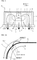
- the bell mouth has vibration states as illustrated in Figs. 2A and 2B .
- Figs. 2A and 2B are schematic diagrams explaining the vibration states of the bell mouth.
- the bell mouth is illustrated as a "bell mouth 5X”
- curved part is illustrated as “curved part 5X-1”
- a front surface of the bell mouth is illustrated as a "bell-mouth front surface 5X-2”
- a rear surface of the bell mouth is illustrated as a "bell-mouth rear surface 5X-3”.
- Figs. 2A and 2B are schematic diagrams explaining the vibration states of the bell mouth.
- the bell mouth is illustrated as a "bell mouth 5X”
- curved part is illustrated as "curved part 5X-1”
- a front surface of the bell mouth is illustrated as a "bell-mouth front surface 5X-2”
- a rear surface of the bell mouth is illustrated as a "bell-mouth rear surface 5X-3”.
- arrows C represent flow of a fluid (air) in a partition close to the bell-mouth front surface 5X-2
- arrows D represent flow of the fluid (air) in a partition close to the bell-mouth rear surface 5X-3.
- dotted lines E represent vibration states of the bell mouth 5X.
- Fig. 2A illustrates a vibration state in a divided vibration mode in which a first "antinode (+)", a “node”, and a second "antinode (-)" appear in parts of the bell mouth included in a vibration propagation path, as represented by the dotted line E.
- Fig. 2B illustrates a vibration state in a divided vibration mode in which a first "antinode (-)", a “node”, and a second "antinode (+)" appear in parts of the bell mouth included in a vibration propagation path, as represented by the dotted line E.
- bumps such as ribs, on the bell-mouth front surface 5X-2 and the bell-mouth rear surface 5X-3 interfere with fluid flow, or generate new sound associated with a fluid.
- care must be taken in providing bumps.
- measures to reduce or eliminate vibration of a bell mouth, or countermeasures against the NZ sound include the following three measures:
- the first measure is intended to increase the stiffness of the bell mouth.
- This measure includes structurally processing the bell mouth to reduce or eliminate vibration of the bell mouth.
- the measure includes allowing the bell mouth to have a rib having a specific shape in such a manner that the rib does not obstruct the air passage.
- the second measure is intended to attenuate vibration of the bell mouth.
- This measure includes fixing a vibration-to-heat transforming unit (vibration-damping element) to the bell mouth. Specifically, the measure includes bonding a vibration-damping element to the bell mouth or applying vibration-damping paint to the bell mouth.
- the third measure is intended to damp vibration of the bell mouth by using a material for the bell mouth.
- This measure includes forming a material containing a vibration-damping material into the bell mouth.
- the measure includes molding the bell mouth from vibration-damping resin.
- Adopting such a measure enables control in the propagation path to achieve overall reduction or elimination of vibration, and ensures attenuation of the NZ sound having a characteristic peak frequency.
- Fig. 3 includes diagrams explaining an example of the first measure to reduce or eliminate vibration of the bell mouth 5 in the air-conditioning apparatus 100.
- Fig. 3 illustrates curved part of the bell mouth 5 as "curved part 5-1", a front surface of the bell mouth 5 as a "bell-mouth front surface 5-2", and a rear surface of the bell mouth 5 as a "bell-mouth rear surface 5-3".
- arrows F represent flow of a fluid (air).
- Fig. 3(a) schematically illustrates the bell-mouth rear surface 5-3 of the curved part 5-1
- Fig. 3(b) schematically illustrates a section of the curved part 5-1 of the bell mouth 5.
- a rib 5-5 serving as a vibration-damping element, is disposed on the bell-mouth rear surface 5-3 of the bell mouth 5 to structurally increase the stiffness of the bell mouth 5.
- the rib 5-5 has a specific shape not to obstruct the air passage.
- the rib 5-5 is disposed at a position corresponding to a node of the vibration mode of the bell mouth 5.
- the rib 5-5 has a mound-like sectional shape having a tip located at the node of the vibration mode (refer to Fig. 3(b) ).
- the rib 5-5 has a rhombus shape in plan view (refer to Fig. 3(a) ).
- the rib 5-5 is molded to have a shape having a longitudinal length in an air flow direction.
- the rib 5-5 has a rounded tip having an angle R of 100 degrees or more.
- Such a shape reduces or eliminates secondary vibration of the rib 5-5 and allows the fluid to smoothly flow without being obstructed by the rib 5-5.
- rib 5-5 is disposed on the curved part 5-1. Any number of ribs 5-5 may be arranged.
- the rib 5-5 and the bell mouth 5 may be molded in one piece.
- the rib 5-5 may be molded as a separate piece and be attached to the bell mouth 5.
- the rib 5-5 may be molded out of the same material as that for the bell mouth 5.
- the rib 5-5 may be molded out of a vibration-damping material capable of transforming vibration into heat. Molding the rib 5-5 out of such a vibration-damping material provides greater vibration attenuating effects.
- Fig. 4 includes diagrams explaining an example of the second measure to reduce or eliminate vibration of the bell mouth 5 in the air-conditioning apparatus 100.
- Fig. 4 illustrates the "curved part 5-1", the "bell-mouth front surface 5-2", and the “bell-mouth rear surface 5-3", as in Fig. 3 .
- arrows F represent flow of a fluid (air), as in Fig. 3 .
- Fig. 4(a) schematically illustrates the bell-mouth rear surface 5-3 of the curved part 5-1
- Fig. 4(b) schematically illustrates a section of the curved part 5-1 of the bell mouth 5
- Fig. 4(c) is a schematic enlarged view of part G in Fig. 4(b) .
- a sheet-like vibration damper 5-6 serving as a vibration-damping element, is bonded to the bell-mouth rear surface 5-3 of the bell mouth 5.
- the vibration damper 5-6 is made of a material capable of transforming vibration into heat. Examples of the material for the vibration damper 5-6 include a mixture containing, as a base material, carbon or polyester-based resin, which tends to thermally expand.
- the vibration damper 5-6 may have any thickness.
- the vibration damper 5-6 having a thickness of, for example, approximately 2 mm is preferably formed.
- a recess 5-7 having a predetermined depth is formed not to obstruct the air passage, and the vibration damper 5-6 is attached to the recess 5-7.
- the recess 5-7 is formed in part that is subjected to the vibration mode of the bell mouth 5, or in an area extending from part in proximity to the fixed end of the bell mouth 5 (or the lower end of the bell mouth 5 in Fig. 1 ) to middle part of the curved part 5-1, and is formed to have a depth in such a manner that the vibration damper 5-6 is received in and bonded to the recess 5-7.
- the depth of the recess 5-7 preferably include the thickness of the vibration damper 5-6 and the thickness of a bonding layer, or is preferably the thickness obtained by adding a little extra thickness to 2 mm so that the vibration damper 5-6 can be fully inserted into the recess 5-7 to obtain a flat surface to which the vibration damper 5-6 is bonded. Consequently, it is only required that the depth of the recess 5-7 is determined depending on the thickness of the vibration damper 5-6.
- the bell-mouth rear surface 5-3 has no protrusion, such as a rib, so that the fluid flowing on the bell mouth 5 is not obstructed. Vibration in the divided vibration mode in the curved part 5-1 of the bell mouth 5 can be effectively attenuated.
- vibration damper 5-6 is bonded to the curved part 5-1. Any number of vibration dampers 5-6 may be arranged.
- Fig. 4(a) illustrates the vibration damper 5-6 having a rectangular shape in plan view as an example
- the vibration damper 5-6 may have any shape in plan view.
- the vibration damper 5-6 may have any thickness.
- the bonded sheet-like vibration damper 5-6 has been described as an example with reference to Fig. 4
- the vibration damper 5-6 may be formed by applying vibration-damping paint.
- the vibration-damping paint may be water-based or oilbased and preferably contains, for example, silicone resin to provide a smooth coating surface.
- the paint containing silicone resin enables a coating to have a smooth surface.
- the sheet-like vibration damper 5-6 may be made of a mixture containing a silicone-based material to have a smooth surface.
- Fig. 5 includes diagrams explaining another or second example of the second measure to reduce or eliminate vibration of the bell mouth 5 in the air-conditioning apparatus 100.
- the vibration damper 5-6 bonded or applied to the bell-mouth rear surface 5-3 has been described as an example with reference to Fig. 4
- Fig. 5 illustrates the vibration damper 5-6 bonded or applied to the bell-mouth front surface 5-2.
- Fig. 5 illustrates the "curved part 5-1", the "bell-mouth front surface 5-2", and the "bell-mouth rear surface 5-3", as in Fig. 4 .
- arrows F represent flow of a fluid (air), as in Fig. 4 .
- Fig. 5(a) schematically illustrates the bell-mouth rear surface 5-3 of the curved part 5-1
- Fig. 5(b) schematically illustrates a section of the curved part 5-1 of the bell mouth
- Fig. 5(c) is a schematic enlarged view of part G in Fig. 5(b) .
- the sheet-like vibration damper 5-6 serving as a vibration-damping element, is bonded to the bell-mouth front surface 5-2 of the bell mouth 5.
- the vibration damper 5-6 is as described with reference to Fig. 4 .
- the recess 5-7 is also as described with reference to Fig. 4 .
- the bell-mouth front surface 5-2 has no protrusion, such as a rib, so that the fluid flowing on the bell mouth 5 is not obstructed. Vibration in the divided vibration mode in the curved part 5-1 of the bell mouth 5 can be effectively attenuated.
- vibration damper 5-6 is bonded to the curved part 5-1. Any number of vibration dampers 5-6 may be arranged.
- Fig. 5(a) illustrates the vibration damper 5-6 having a rectangular shape in plan view as an example
- the vibration damper 5-6 may have any shape in plan view.
- the vibration damper 5-6 may have any thickness.
- the vibration damper 5-6 bonded or applied to either one of the bell-mouth front surface 5-2 and the bell-mouth rear surface 5-3 of the bell mouth 5 is illustrated as an example in Figs. 4 and 5
- the vibration damper 5-6 may be bonded or applied to each of the bell-mouth front surface 5-2 and the bell-mouth rear surface 5-3 of the bell mouth 5.
- the number of vibration dampers 5-6 bonded or applied to the bell-mouth front surface 5-2 does not have to be equal to the number of vibration dampers 5-6 bonded or applied to the bell-mouth rear surface 5-3.
- the vibration dampers 5-6 may be bonded or applied to the bell-mouth front surface 5-2 and the bell-mouth rear surface 5-3 in such a manner that the vibration dampers 5-6 on the bell-mouth front surface 5-2 are not aligned with those on the bell-mouth rear surface 5-3.
- An example of the third measure is to form a material containing a vibration-damping material into the bell mouth 5 and thus damp vibration of the bell mouth 5 by using the material.
- the material for the bell mouth 5 is a mixture containing carbon, which can exhibit vibration-damping performance, or any of polyester-based resins, which tend to thermally expand, and further containing a proper amount of resin to be originally used to make the bell mouth 5.
- the bell mouth 5 made of such a material allows vibration of the bell mouth 5 to be transformed into heat, thus reducing or eliminating the vibration.
- the vibration-damping material is preferably mixed into the resin to be originally used to make the bell mouth 5.
- the vibration-damping material is preferably mixed by up to approximately 50% of the total amount of the mixture in consideration of the fluidity of the mixture containing the vibration-damping material in a "mold" for molding the bell mouth 5.
- the bell mouth 5 is advantageously allowed to have a smaller thickness than those in the related art.
- related-art bell mouths require a thickness of approximately 3 mm.
- the bell mouth 5 having a thickness up to approximately 1.5 mm can offer advantages similar to those in the related art.
- the whole of the bell mouth 5 may be molded out of a resin mixture containing a vibration-damping material (polymer). Part of the bell mouth 5 may be molded out of this mixture. When part of the bell mouth 5 is molded out of the resin mixture containing the vibration-damping material (polymer), insert molding and traditional resin can be used to make the bell mouth 5.
- the air-conditioning apparatus 100 has an effect of reducing peak frequencies of vibration-induced sound. This effect will be described below with reference to Fig. 6.
- Fig. 6 is a graph explaining the effect of reducing peak frequencies of vibration-induced sound, and the effect is obtained by subjecting the bell mouth 5 of the air-conditioning apparatus 100 to any of the first to third measures.
- a full line represents the frequency characteristic of vibration-induced sound in the air-conditioning apparatus 100 and a dotted line represents the frequency characteristic of vibration-induced sound in a bell mouth subjected to none of the first to third measures.
- the horizontal axis represents the frequency and the vertical axis represents the sound pressure level.
- the air-conditioning apparatus 100 includes the fan 6 as a component and the air passage 50 is defined by the foam material 10.
- the foam material 10 may be vibrated by the fluid and thus generate “vibration”.
- the foam material 10 may resonate with vibration associated with rotation of the motor 7 and the fan 6, propagate the vibration through the structure, and thus generate "vibration”.
- the "vibration" generated by the foam material 10 may be propagated to the components constituting the air-conditioning apparatus 100, for example, the bell mouth 5. In other words, rotation of the fan 6 generates NZ sound, resulting in vibration of the bell mouth 5.
- the frequency characteristic of the bell mouth subjected to none of the first to third measures tends to have a high peak frequency in a frequency band of 100 Hz or lower.
- the air-conditioning apparatus 100 includes the bell mouth 5 subjected to any of the first to third measures, as represented by the full line in Fig. 6 , peak frequencies are reduced by 5 dB or more in a wide frequency band.
- the air-conditioning apparatus 100 includes the bell mouth 5 subjected to any of the first to third measures, the air-conditioning apparatus 100 ensures a reduction in vibration-induced sound resulting from NZ sound associated with rotation of the fan 6.
- the bell mouth 5 subjected to any of the first to third measures does not obstruct air flow through the air-conditioning apparatus 100.
- the bell mouth 5 may be made by using a combination of these measures. Furthermore, the third measure is intended to be used together with at least one of the first and second measures.
Landscapes
- Engineering & Computer Science (AREA)
- Mechanical Engineering (AREA)
- General Engineering & Computer Science (AREA)
- Chemical & Material Sciences (AREA)
- Combustion & Propulsion (AREA)
- Physics & Mathematics (AREA)
- Acoustics & Sound (AREA)
- Multimedia (AREA)
- Aviation & Aerospace Engineering (AREA)
- Fluid Mechanics (AREA)
- Structures Of Non-Positive Displacement Pumps (AREA)
- Air-Conditioning Room Units, And Self-Contained Units In General (AREA)
Abstract
Description
- The present invention relates to air-conditioning apparatuses including air passages through which air flows, and in particular, relates to an air-conditioning apparatus including a housing structure that achieves reduction of housing-vibration-induced sound resulting from rotation of a fan.
- For example, as described in
Patent Literature 1, there has been a method for reducing noise in a centrifugal air-sending device. To reduce noise of, for example, vibration resulting from rotation of a fan, this method includes reducing a frequency that contributes to noise by providing a resonant space in proximity to an air inlet of a bell mouth. - Furthermore, as described in
Patent Literature 2, there has been an air-conditioning-apparatus outdoor unit including a bell mouth having ribs (strengthening ribs 53) arranged at predetermined positions on a rear surface of the bell mouth to reduce vibration of the bell mouth caused by a fluid flowing through the bell mouth. -
- Patent Literature 1: Japanese Unexamined Patent Application Publication No.
2009-264121 - Patent Literature 2: Japanese Unexamined Patent Application Publication No.
2010-127594 - In the related art described in
Patent Literature 1, the resonant space is provided at a rear of the bell mouth. Disadvantageously, a fluid flowing at the rear of the bell mouth may create turbulence in the resonant space, causing generation of new vibration-induced sound (noise). - In the related art described in
Patent Literature 2, many ribs are arranged at predetermined intervals in a circumferential direction. For resonant vibration propagating from a housing, however, the ribs may not be arranged at suitable positions for reducing vibration resulting from resonance. Some ribs are of little or no use in reducing vibration resulting from, for example, resonance. Furthermore, the ribs may create new vibration by themselves, causing generation of new vibration-induced sound. - Noise includes not only sound of a fluid through a fan but also resonance sound of a structure having an air passage and housing-vibration-induced sound of a structure. The resonance sound of a structure having an air passage and the housing-vibration-induced sound of a structure are in form of noise that has a plurality of characteristic peak frequencies and is unpleasant to hear.
- In particular, rotation of a device, for example, a fan, generates sound (typically referred to as NZ sound) having a frequency characteristic obtained by multiplying a rotation period (N) by the number of blades (Z). As such sound, sound resulting from a fluid passing through a fan is known. Surprisingly, however, it is relatively unknown that noise includes not only the above-described sounds but also sound resulting from vibration of a housing vibrated by a fluid passing through the housing.
- Such vibration can include a vibration component resulting from fluid-induced vibration of a housing, a vibration component propagated to the housing, serving as a structure, from, for example, a motor to which a fan is connected and fixed, and a vibration component resulting from resonance with natural vibration of the housing structure. It has been found that resonance with natural vibration of the housing structure can cause resonance sound to be generated from unexpected part of the housing structure and such resonance sound becomes a problem.
- The present invention has been made in view of the above-described problems, and aims to provide an air-conditioning apparatus in which a countermeasure against vibration-induced sound resulting from vibration of a housing is adopted and in which unpleasant sound having a peak frequency of the vibration-induced sound resulting from vibration of the housing is attenuated without obstruction to fluid flow.
- An air-conditioning apparatus according to an embodiment of the present invention includes a housing having an air inlet and an air outlet, a fan disposed in the housing, and a bell mouth through which a fluid flowing from the air inlet to the air outlet passes in association with rotation of the fan. The bell mouth includes curved part having a curved sectional shape in a fluid flow direction and a vibration-damping element disposed on at least one of a front surface and a rear surface of the curved part. The vibration-damping element is disposed at a position corresponding to a node of vibration of the bell mouth.
- As the vibration-damping element is disposed at the position corresponding to a node of a vibration mode of the bell mouth on at least one of the rear surface and the front surface of the curved part of the bell mouth, the air-conditioning apparatus according to an embodiment of the present invention can reduce or eliminate divided vibration of the bell mouth caused by rotation of the fan, thus effectively attenuating a peak frequency of NZ sound generated by vibration of the bell mouth.
-
-
Fig. 1 is a schematic side view illustrating a schematic exemplary configuration of an air-conditioning apparatus according to Embodiment of the present invention as viewed from a side of the air-conditioning apparatus. -
Fig. 2A is a schematic diagram explaining a vibration state of a bell mouth. -
Fig. 2B is a schematic diagram explaining another vibration state of the bell mouth. -
Fig. 3 includes diagrams explaining an example of a first measure to reduce or eliminate vibration of the bell mouth in the air-conditioning apparatus according to Embodiment of the present invention. -
Fig. 4 includes diagrams explaining an example of a second measure to reduce or eliminate vibration of the bell mouth in the air-conditioning apparatus according to Embodiment of the present invention. -
Fig. 5 includes diagrams explaining another example of the second measure to reduce or eliminate vibration of the bell mouth in the air-conditioning apparatus according to Embodiment of the present invention. -
Fig. 6 is a graph explaining an effect of reducing peak frequencies of vibration-induced sound, the effect being obtained by subjecting the bell mouth of the air-conditioning apparatus according to Embodiment of the present invention to any of the first to third measures. - Embodiment of the present invention will be described with reference to the drawings. Note that the relationship between the sizes of components illustrated in the following drawings including
Fig. 1 may differ from that of actual ones. Furthermore, note that components designated by the same reference signs in the following drawings includingFig. 1 are the same components or equivalents. This note applies to the entire description herein. In addition, note that the forms of components described herein are intended to be illustrative only and the forms of the components are not intended to be limited to those described herein. -
Fig. 1 is a schematic side view illustrating an exemplary schematic configuration of an air-conditioning apparatus 100 according to Embodiment of the present invention as viewed from a side of the air-conditioning apparatus 100. The air-conditioning apparatus 100 will be described below with reference toFig. 1 . InFig. 1 , dotted-line arrows A represent air flow and dotted-line arrows B represent sound flow. - The air-
conditioning apparatus 100 has functions of an indoor unit installed in an indoor space (air-conditioned space) in, for example, a house, a building, or an apartment, and supplies conditioned air to the air-conditioned space by using a refrigeration cycle. Although the air-conditioning apparatus 100 of a ceiling embedded type will be described herein as an example, the type of the air-conditioning apparatus 100 is not limited to this example. The present invention is applicable to any type of air-conditioning apparatus, for example, a ceiling suspended type, a wall hung type, or a floor standing type. - The air-
conditioning apparatus 100 includes ahousing 1 accommodating anair passage 50 through which the air is circulated. - The air-
conditioning apparatus 100 further includes amotor 7 suspended from substantially central part of an inner upper surface of thehousing 1, afan 6 attached to a shaft of themotor 7, and aheat exchanger 9 disposed around thefan 6. The air-conditioning apparatus 100 further includes a front panel 4 attached to lower part of thehousing 1. - The
housing 1 is box-shaped and has an open bottom,sides 2, and atop 3. Thehousing 1, serving as a body of the air-conditioning apparatus 100, accommodates themotor 7, thefan 6, and theheat exchanger 9. Thehousing 1 further accommodates theair passage 50 through which the air is circulated. Driving thefan 6 circulates the air through the air passage 50 (as represented by the dotted-line arrows A). - In addition, a
foam material 10 is disposed at an interior of thesides 2 and thetop 3 of thehousing 1. A wall may be interposed between thefoam material 10 and theair passage 50. - The
motor 7 is suspended from thehousing 1 bysupport rubber 8 in such a manner that the shaft of the motor extends downward, and rotates thefan 6. Specifically, thesupport rubber 8 is fastened to the inner surface of thetop 3 of thehousing 1, and themotor 7 is fastened to thesupport rubber 8. - The
fan 6 is fastened to the shaft of themotor 7 in such a manner that an air inlet of the fan faces downward. Thefan 6 suctions the air from the air-conditioned space, such as an indoor space where the air-conditioning apparatus 100 is installed, allows the air to pass through theheat exchanger 9, and blows the air into the air-conditioned space. - The front panel 4 has an
air inlet 4a through which the air is suctioned into thehousing 1 and anair outlet 4b through which the air is discharged out of thehousing 1. Theair inlet 4a is open and located at central part of thehousing 1 in plan view. Theair outlet 4b is open and located around theair inlet 4a. Abell mouth 5 is disposed at theair inlet 4a. Thebell mouth 5 regulates the flow of the air suctioned from the air-conditioned space into thehousing 1 to reduce or eliminate noise and thus reduce or eliminate a degradation in user comfort. - The
heat exchanger 9 acts as a condenser in a heating operation, acts as an evaporator in a cooling operation, and exchanges heat between the air supplied from thefan 6 and a heat medium, such as refrigerant, supplied from a heat source unit (outdoor unit), which is not illustrated, to produce heating air or cooling air. - The
air passage 50 is provided inside thehousing 1 in such a manner that theair inlet 4a communicates with theair outlet 4b. In theair passage 50, the air suctioned from the air-conditioned space through theair inlet 4a flows through thefan 6, the inside of theheat exchanger 9, the outside of theheat exchanger 9, and theair outlet 4b in the stated order. - A grille having a plurality of openings through which the air to be suctioned into the
housing 1 passes and an air filter for removing dust contained in the air are preferably arranged at theair inlet 4a of the front panel 4 in such a manner that the air filter is located above the grille. - A vertical air-directing vane for adjusting a blowing direction in which the air is blown is typically disposed at the
air outlet 4b of the front panel 4. - Furthermore, the front panel 4 is disposed in such a manner that, for example, a lower surface of the front panel 4 is substantially flush with a ceiling to which the front panel 4 is installed.
- As sound that is generated in a device including a fan, sound resulting from a fluid passing through the fan is known. Surprisingly, it is relatively unknown that examples of the sound that is generated in a device including a fan further include sound resulting from vibration of a housing, or housing-vibration-induced sound. It has been found that housing-vibration-induced sound includes a vibration-induced sound component resulting from fluid-induced vibration of a housing, a vibration-induced sound component propagated to the housing, serving as a structure, from, for example, a motor to which a fan is connected and fixed, and resonance sound that results from resonance with natural vibration of the housing structure and that is generated from unexpected part of the housing structure.
- Like the
air passage 50 in the air-conditioning apparatus 100, a sound propagation path in a device including a fan may be defined by, for example, a heat-insulating foam material. The foam material may be vibrated by a fluid or may resonate with vibration associated with rotation of a motor or a fan, propagate the vibration through the structure, and thus generate "vibration". The "vibration" generated by the foam material may be propagated to components constituting the device including the fan, thus forcibly vibrating the components or causing resonance-induced vibration of the components. This action results in noise unpleasant to hear. - This noise results from vibration of the components constituting the device. Specifically, rotation of the fan generates NZ sound. The NZ sound directly vibrates an air passage structure, resulting in vibration of a bell mouth disposed at an air inlet. The NZ sound is obtained by multiplying a rotation period (N) of the fan by the number (Z) of blades. Such a phenomenon can similarly occur in the air-
conditioning apparatus 100. - Atypical bell mouth (including the bell mouth 5), which serves as an air passage, has a curved vertical section not to obstruct air flow. Vibration associated with rotation of a fan can be propagated to the bell mouth having such a structure through a housing structure. The bell mouth has one end coupled to the housing and is thus inevitably included in a vibration propagation path. Propagation of the vibration associated with the rotation of the fan to the bell mouth causes a divided vibration mode in which a first "antinode (+)", a "node", and another "antinode (-)" appear in parts of the bell mouth included in the vibration propagation path. This vibration mode has a feature in which the amplitude of vibration of part close to the housing is larger than that of part remote from the housing.
- The bell mouth has vibration states as illustrated in
Figs. 2A and2B .Figs. 2A and2B are schematic diagrams explaining the vibration states of the bell mouth. InFigs. 2A and2B , the bell mouth is illustrated as a "bell mouth 5X", curved part is illustrated as "curved part 5X-1", a front surface of the bell mouth is illustrated as a "bell-mouth front surface 5X-2", and a rear surface of the bell mouth is illustrated as a "bell-mouthrear surface 5X-3". InFigs. 2A and2B , arrows C represent flow of a fluid (air) in a partition close to the bell-mouth front surface 5X-2, and arrows D represent flow of the fluid (air) in a partition close to the bell-mouthrear surface 5X-3. Furthermore, dotted lines E represent vibration states of thebell mouth 5X. -
Fig. 2A illustrates a vibration state in a divided vibration mode in which a first "antinode (+)", a "node", and a second "antinode (-)" appear in parts of the bell mouth included in a vibration propagation path, as represented by the dotted line E. -
Fig. 2B illustrates a vibration state in a divided vibration mode in which a first "antinode (-)", a "node", and a second "antinode (+)" appear in parts of the bell mouth included in a vibration propagation path, as represented by the dotted line E. - These figures demonstrate that reducing or eliminating vibration of the
bell mouth 5X is an effective countermeasure against the NZ sound and this countermeasure differs from a countermeasure against fluid-induced vibration from a fan. - As the
bell mouth 5X serves as an air passage, bumps, such as ribs, on the bell-mouth front surface 5X-2 and the bell-mouthrear surface 5X-3 interfere with fluid flow, or generate new sound associated with a fluid. As even merely forming a rib having a simple shape causes the same problem, care must be taken in providing bumps. - Examples of measures to reduce or eliminate vibration of a bell mouth, or countermeasures against the NZ sound, include the following three measures:
- First measure including performing a vibration-damping process on the bell mouth, serving as an air flow passage;
- Second measure including performing a vibration attenuation process on a vibration propagation path including a housing and the bell mouth; and
- Third measure including adopting a countermeasure against vibration to make a bell mouth body.
- The first measure is intended to increase the stiffness of the bell mouth. This measure includes structurally processing the bell mouth to reduce or eliminate vibration of the bell mouth. Specifically, the measure includes allowing the bell mouth to have a rib having a specific shape in such a manner that the rib does not obstruct the air passage.
- The second measure is intended to attenuate vibration of the bell mouth. This measure includes fixing a vibration-to-heat transforming unit (vibration-damping element) to the bell mouth. Specifically, the measure includes bonding a vibration-damping element to the bell mouth or applying vibration-damping paint to the bell mouth.
- The third measure is intended to damp vibration of the bell mouth by using a material for the bell mouth. This measure includes forming a material containing a vibration-damping material into the bell mouth. Specifically, the measure includes molding the bell mouth from vibration-damping resin.
- Adopting such a measure enables control in the propagation path to achieve overall reduction or elimination of vibration, and ensures attenuation of the NZ sound having a characteristic peak frequency.
-
Fig. 3 includes diagrams explaining an example of the first measure to reduce or eliminate vibration of thebell mouth 5 in the air-conditioning apparatus 100.Fig. 3 illustrates curved part of thebell mouth 5 as "curved part 5-1", a front surface of thebell mouth 5 as a "bell-mouth front surface 5-2", and a rear surface of thebell mouth 5 as a "bell-mouth rear surface 5-3". InFig. 3 , arrows F represent flow of a fluid (air).Fig. 3(a) schematically illustrates the bell-mouth rear surface 5-3 of the curved part 5-1 andFig. 3(b) schematically illustrates a section of the curved part 5-1 of thebell mouth 5. - As illustrated in
Fig. 3 , in this example of the first measure, a rib 5-5, serving as a vibration-damping element, is disposed on the bell-mouth rear surface 5-3 of thebell mouth 5 to structurally increase the stiffness of thebell mouth 5. The rib 5-5 has a specific shape not to obstruct the air passage. The rib 5-5 is disposed at a position corresponding to a node of the vibration mode of thebell mouth 5. - Specifically, the rib 5-5 has a mound-like sectional shape having a tip located at the node of the vibration mode (refer to
Fig. 3(b) ). The rib 5-5 has a rhombus shape in plan view (refer toFig. 3(a) ). In other words, the rib 5-5 is molded to have a shape having a longitudinal length in an air flow direction. The rib 5-5 has a rounded tip having an angle R of 100 degrees or more. - Such a shape reduces or eliminates secondary vibration of the rib 5-5 and allows the fluid to smoothly flow without being obstructed by the rib 5-5.
- It is only required that at least one rib 5-5 is disposed on the curved part 5-1. Any number of ribs 5-5 may be arranged. The rib 5-5 and the
bell mouth 5 may be molded in one piece. The rib 5-5 may be molded as a separate piece and be attached to thebell mouth 5. - The rib 5-5 may be molded out of the same material as that for the
bell mouth 5. Alternatively, the rib 5-5 may be molded out of a vibration-damping material capable of transforming vibration into heat. Molding the rib 5-5 out of such a vibration-damping material provides greater vibration attenuating effects. -
Fig. 4 includes diagrams explaining an example of the second measure to reduce or eliminate vibration of thebell mouth 5 in the air-conditioning apparatus 100.Fig. 4 illustrates the "curved part 5-1", the "bell-mouth front surface 5-2", and the "bell-mouth rear surface 5-3", as inFig. 3 . InFig. 4 , arrows F represent flow of a fluid (air), as inFig. 3 .Fig. 4(a) schematically illustrates the bell-mouth rear surface 5-3 of the curved part 5-1,Fig. 4(b) schematically illustrates a section of the curved part 5-1 of thebell mouth 5, andFig. 4(c) is a schematic enlarged view of part G inFig. 4(b) . - As illustrated in
Fig. 4 , in this example of the second measure, a sheet-like vibration damper 5-6, serving as a vibration-damping element, is bonded to the bell-mouth rear surface 5-3 of thebell mouth 5. The vibration damper 5-6 is made of a material capable of transforming vibration into heat. Examples of the material for the vibration damper 5-6 include a mixture containing, as a base material, carbon or polyester-based resin, which tends to thermally expand. The vibration damper 5-6 may have any thickness. The vibration damper 5-6 having a thickness of, for example, approximately 2 mm is preferably formed. - Furthermore, a recess 5-7 having a predetermined depth is formed not to obstruct the air passage, and the vibration damper 5-6 is attached to the recess 5-7. Specifically, the recess 5-7 is formed in part that is subjected to the vibration mode of the
bell mouth 5, or in an area extending from part in proximity to the fixed end of the bell mouth 5 (or the lower end of thebell mouth 5 inFig. 1 ) to middle part of the curved part 5-1, and is formed to have a depth in such a manner that the vibration damper 5-6 is received in and bonded to the recess 5-7. For example, the depth of the recess 5-7 preferably include the thickness of the vibration damper 5-6 and the thickness of a bonding layer, or is preferably the thickness obtained by adding a little extra thickness to 2 mm so that the vibration damper 5-6 can be fully inserted into the recess 5-7 to obtain a flat surface to which the vibration damper 5-6 is bonded. Consequently, it is only required that the depth of the recess 5-7 is determined depending on the thickness of the vibration damper 5-6. - Consequently, the bell-mouth rear surface 5-3 has no protrusion, such as a rib, so that the fluid flowing on the
bell mouth 5 is not obstructed. Vibration in the divided vibration mode in the curved part 5-1 of thebell mouth 5 can be effectively attenuated. - It is only required that at least one vibration damper 5-6 is bonded to the curved part 5-1. Any number of vibration dampers 5-6 may be arranged.
- Although
Fig. 4(a) illustrates the vibration damper 5-6 having a rectangular shape in plan view as an example, the vibration damper 5-6 may have any shape in plan view. Furthermore, the vibration damper 5-6 may have any thickness. Although the bonded sheet-like vibration damper 5-6 has been described as an example with reference toFig. 4 , the vibration damper 5-6 may be formed by applying vibration-damping paint. The vibration-damping paint may be water-based or oilbased and preferably contains, for example, silicone resin to provide a smooth coating surface. The paint containing silicone resin enables a coating to have a smooth surface. Similarly, the sheet-like vibration damper 5-6 may be made of a mixture containing a silicone-based material to have a smooth surface. -
Fig. 5 includes diagrams explaining another or second example of the second measure to reduce or eliminate vibration of thebell mouth 5 in the air-conditioning apparatus 100. Although the vibration damper 5-6 bonded or applied to the bell-mouth rear surface 5-3 has been described as an example with reference toFig. 4 ,Fig. 5 illustrates the vibration damper 5-6 bonded or applied to the bell-mouth front surface 5-2.Fig. 5 illustrates the "curved part 5-1", the "bell-mouth front surface 5-2", and the "bell-mouth rear surface 5-3", as inFig. 4 . InFig. 5 , arrows F represent flow of a fluid (air), as inFig. 4 .Fig. 5(a) schematically illustrates the bell-mouth rear surface 5-3 of the curved part 5-1,Fig. 5(b) schematically illustrates a section of the curved part 5-1 of thebell mouth 5, andFig. 5(c) is a schematic enlarged view of part G inFig. 5(b) . - As illustrated in
Fig. 5 , in the second example of the second measure, the sheet-like vibration damper 5-6, serving as a vibration-damping element, is bonded to the bell-mouth front surface 5-2 of thebell mouth 5. The vibration damper 5-6 is as described with reference toFig. 4 . In addition, the recess 5-7 is also as described with reference toFig. 4 . - Consequently, the bell-mouth front surface 5-2 has no protrusion, such as a rib, so that the fluid flowing on the
bell mouth 5 is not obstructed. Vibration in the divided vibration mode in the curved part 5-1 of thebell mouth 5 can be effectively attenuated. - It is only required that at least one vibration damper 5-6 is bonded to the curved part 5-1. Any number of vibration dampers 5-6 may be arranged.
- Although
Fig. 5(a) illustrates the vibration damper 5-6 having a rectangular shape in plan view as an example, the vibration damper 5-6 may have any shape in plan view. Furthermore, the vibration damper 5-6 may have any thickness. - Although the vibration damper 5-6 bonded or applied to either one of the bell-mouth front surface 5-2 and the bell-mouth rear surface 5-3 of the
bell mouth 5 is illustrated as an example inFigs. 4 and5 , the vibration damper 5-6 may be bonded or applied to each of the bell-mouth front surface 5-2 and the bell-mouth rear surface 5-3 of thebell mouth 5. In such a case, the number of vibration dampers 5-6 bonded or applied to the bell-mouth front surface 5-2 does not have to be equal to the number of vibration dampers 5-6 bonded or applied to the bell-mouth rear surface 5-3. The vibration dampers 5-6 may be bonded or applied to the bell-mouth front surface 5-2 and the bell-mouth rear surface 5-3 in such a manner that the vibration dampers 5-6 on the bell-mouth front surface 5-2 are not aligned with those on the bell-mouth rear surface 5-3. - An example of the third measure is to form a material containing a vibration-damping material into the
bell mouth 5 and thus damp vibration of thebell mouth 5 by using the material. The material for thebell mouth 5 is a mixture containing carbon, which can exhibit vibration-damping performance, or any of polyester-based resins, which tend to thermally expand, and further containing a proper amount of resin to be originally used to make thebell mouth 5. Thebell mouth 5 made of such a material allows vibration of thebell mouth 5 to be transformed into heat, thus reducing or eliminating the vibration. - Furthermore, mixing a silicone-based material into the above-described material enables the surfaces of the
bell mouth 5 to remain smooth. - The vibration-damping material is preferably mixed into the resin to be originally used to make the
bell mouth 5. The vibration-damping material is preferably mixed by up to approximately 50% of the total amount of the mixture in consideration of the fluidity of the mixture containing the vibration-damping material in a "mold" for molding thebell mouth 5. - As the thickness of the
bell mouth 5 itself achieves reduction or elimination of vibration, thebell mouth 5 is advantageously allowed to have a smaller thickness than those in the related art. For example, related-art bell mouths require a thickness of approximately 3 mm. In contrast, thebell mouth 5 having a thickness up to approximately 1.5 mm can offer advantages similar to those in the related art. - The whole of the
bell mouth 5 may be molded out of a resin mixture containing a vibration-damping material (polymer). Part of thebell mouth 5 may be molded out of this mixture. When part of thebell mouth 5 is molded out of the resin mixture containing the vibration-damping material (polymer), insert molding and traditional resin can be used to make thebell mouth 5. - The air-
conditioning apparatus 100 has an effect of reducing peak frequencies of vibration-induced sound. This effect will be described below with reference toFig. 6. Fig. 6 is a graph explaining the effect of reducing peak frequencies of vibration-induced sound, and the effect is obtained by subjecting thebell mouth 5 of the air-conditioning apparatus 100 to any of the first to third measures. InFig. 6 , a full line represents the frequency characteristic of vibration-induced sound in the air-conditioning apparatus 100 and a dotted line represents the frequency characteristic of vibration-induced sound in a bell mouth subjected to none of the first to third measures. InFig. 6 , the horizontal axis represents the frequency and the vertical axis represents the sound pressure level. - The air-
conditioning apparatus 100 includes thefan 6 as a component and theair passage 50 is defined by thefoam material 10. In such a configuration, thefoam material 10 may be vibrated by the fluid and thus generate "vibration". Thefoam material 10 may resonate with vibration associated with rotation of themotor 7 and thefan 6, propagate the vibration through the structure, and thus generate "vibration". The "vibration" generated by thefoam material 10 may be propagated to the components constituting the air-conditioning apparatus 100, for example, thebell mouth 5. In other words, rotation of thefan 6 generates NZ sound, resulting in vibration of thebell mouth 5. - As represented by the dotted line in
Fig. 6 , the frequency characteristic of the bell mouth subjected to none of the first to third measures tends to have a high peak frequency in a frequency band of 100 Hz or lower. - In contrast, as the air-
conditioning apparatus 100 includes thebell mouth 5 subjected to any of the first to third measures, as represented by the full line inFig. 6 , peak frequencies are reduced by 5 dB or more in a wide frequency band. - As described above, as the air-
conditioning apparatus 100 includes thebell mouth 5 subjected to any of the first to third measures, the air-conditioning apparatus 100 ensures a reduction in vibration-induced sound resulting from NZ sound associated with rotation of thefan 6. In addition, thebell mouth 5 subjected to any of the first to third measures does not obstruct air flow through the air-conditioning apparatus 100. - Although the first to third measures have been described as individual countermeasures against vibration of the
bell mouth 5 in Embodiment, thebell mouth 5 may be made by using a combination of these measures. Furthermore, the third measure is intended to be used together with at least one of the first and second measures. - 1
housing 2side 3 top 4front panel 4a air inlet 4b air outlet 5 bell mouth 5-1 curved part 5-2 bell-mouth front surface 5-3 bell-mouth rear surface 5-5 rib 5-6 vibration damper 5-7recess 5X bell mouth 5X-1curved part 5X-2 bell-mouth front surface 5X-3 bell-mouthrear surface 6fan 7motor 8support rubber 9heat exchanger 10foam material 50air passage 100 air-conditioning apparatus
Claims (10)
- An air-conditioning apparatus, comprising:a housing having an air inlet and an air outlet;a fan disposed in the housing; anda bell mouth through which a fluid flowing from the air inlet to the air outlet passes in association with rotation of the fan,the bell mouth including curved part having a curved sectional shape in a fluid flow direction and a vibration-damping element disposed on at least one of a front surface and a rear surface of the curved part,the vibration-damping element being disposed at a position corresponding to a node of vibration of the bell mouth.
- The air-conditioning apparatus of claim 1, wherein the vibration-damping element is formed as a rib having a rounded tip having an angle of 100 degrees or more.
- The air-conditioning apparatus of claim 2, wherein the rib has a rhombus shape in plan view, the rhombus shape having a longitudinal length in the fluid flow direction.
- The air-conditioning apparatus of claim 2 or 3, wherein the rib is made of a material capable of transforming vibration into heat.
- The air-conditioning apparatus of claim 1, wherein the vibration-damping element is formed in a sheet made of a material containing a material capable of transforming vibration into heat.
- The air-conditioning apparatus of claim 1, wherein the vibration-damping element is formed by applying a material containing a material capable of transforming vibration into heat.
- The air-conditioning apparatus of claim 5 or 6, wherein at least one of the front surface and the rear surface of the curved part has a recess to which the vibration-damping element is attached.
- The air-conditioning apparatus of any one of claims 5 to 7, wherein the vibration-damping element comprises a mixture containing a silicone-based material and the material capable of transforming vibration into heat.
- The air-conditioning apparatus of any one of claims 1 to 8, wherein all or part of the bell mouth contains vibration-damping resin.
- The air-conditioning apparatus of any one of claims 1 to 9, further comprising a foam material disposed at an interior of a side and a top of the housing.
Applications Claiming Priority (1)
| Application Number | Priority Date | Filing Date | Title |
|---|---|---|---|
| PCT/JP2016/087762 WO2018116340A1 (en) | 2016-12-19 | 2016-12-19 | Air conditioning device |
Publications (3)
| Publication Number | Publication Date |
|---|---|
| EP3557145A1 true EP3557145A1 (en) | 2019-10-23 |
| EP3557145A4 EP3557145A4 (en) | 2019-12-11 |
| EP3557145B1 EP3557145B1 (en) | 2023-10-18 |
Family
ID=62626025
Family Applications (1)
| Application Number | Title | Priority Date | Filing Date |
|---|---|---|---|
| EP16924821.8A Active EP3557145B1 (en) | 2016-12-19 | 2016-12-19 | Air conditioning device |
Country Status (5)
| Country | Link |
|---|---|
| US (1) | US10989440B2 (en) |
| EP (1) | EP3557145B1 (en) |
| JP (1) | JP6745908B2 (en) |
| CN (1) | CN110073147B (en) |
| WO (1) | WO2018116340A1 (en) |
Families Citing this family (1)
| Publication number | Priority date | Publication date | Assignee | Title |
|---|---|---|---|---|
| CN113700674A (en) * | 2021-09-30 | 2021-11-26 | 西安泛仕达流体机械有限公司 | Cup joint butt joint current collector and fan thereof |
Family Cites Families (20)
| Publication number | Priority date | Publication date | Assignee | Title |
|---|---|---|---|---|
| JPS62122241U (en) * | 1986-01-27 | 1987-08-03 | ||
| JP3279834B2 (en) * | 1994-09-21 | 2002-04-30 | 松下精工株式会社 | Recessed ceiling ventilation fan |
| JPH08159098A (en) * | 1994-12-05 | 1996-06-18 | Daikin Ind Ltd | Bellmouth |
| JP3303860B2 (en) * | 1999-10-26 | 2002-07-22 | ダイキン工業株式会社 | Centrifugal blower and air conditioner |
| JP4276363B2 (en) | 2000-07-31 | 2009-06-10 | 株式会社小松製作所 | Method for forming porous sound absorbing material used for noise reduction mechanism of fan device |
| KR20030035328A (en) * | 2001-10-31 | 2003-05-09 | 삼성전자주식회사 | Outdoor unit of air conditioner |
| WO2004023001A1 (en) | 2002-09-02 | 2004-03-18 | Komatsu Ltd. | Vibration damping device and bucket for construction machine |
| JP3698150B2 (en) * | 2003-05-09 | 2005-09-21 | ダイキン工業株式会社 | Centrifugal blower |
| KR101116675B1 (en) | 2004-04-08 | 2012-03-07 | 삼성전자주식회사 | Air conditioner |
| US7883312B2 (en) * | 2005-03-31 | 2011-02-08 | Mitsubishi Heavy Industries, Ltd. | Centrifugal blower |
| JP4017003B2 (en) * | 2005-09-30 | 2007-12-05 | ダイキン工業株式会社 | Centrifugal fan and air conditioner using the same |
| JP2008207611A (en) * | 2007-02-23 | 2008-09-11 | Mitsubishi Heavy Ind Ltd | Air-conditioning unit and vehicular air-conditioner |
| JP2009264121A (en) | 2008-04-22 | 2009-11-12 | Panasonic Corp | Centrifugal blower, and method for reducing noise of centrifugal fan |
| JP4823294B2 (en) * | 2008-11-04 | 2011-11-24 | 三菱電機株式会社 | Blower and heat pump device using this blower |
| JP2010127595A (en) * | 2008-12-01 | 2010-06-10 | Fujitsu General Ltd | Outdoor unit of air conditioner |
| JP2010127594A (en) * | 2008-12-01 | 2010-06-10 | Fujitsu General Ltd | Outdoor unit of air conditioner |
| KR101812014B1 (en) * | 2010-12-03 | 2017-12-26 | 엘지전자 주식회사 | Brower for air conditioner |
| JP5709607B2 (en) * | 2011-03-30 | 2015-04-30 | 三菱電機株式会社 | Fan guard, outdoor unit and refrigeration cycle apparatus |
| JP2013228168A (en) * | 2012-04-26 | 2013-11-07 | Mitsubishi Electric Corp | Air conditioner |
| KR102199376B1 (en) * | 2013-07-12 | 2021-01-06 | 엘지전자 주식회사 | Centrifugal blower and air conditioner using the same |
-
2016
- 2016-12-19 US US16/333,806 patent/US10989440B2/en not_active Expired - Fee Related
- 2016-12-19 EP EP16924821.8A patent/EP3557145B1/en active Active
- 2016-12-19 JP JP2018557239A patent/JP6745908B2/en not_active Expired - Fee Related
- 2016-12-19 WO PCT/JP2016/087762 patent/WO2018116340A1/en not_active Ceased
- 2016-12-19 CN CN201680090678.0A patent/CN110073147B/en not_active Expired - Fee Related
Also Published As
| Publication number | Publication date |
|---|---|
| CN110073147B (en) | 2021-07-02 |
| WO2018116340A1 (en) | 2018-06-28 |
| EP3557145A4 (en) | 2019-12-11 |
| US10989440B2 (en) | 2021-04-27 |
| EP3557145B1 (en) | 2023-10-18 |
| CN110073147A (en) | 2019-07-30 |
| JP6745908B2 (en) | 2020-08-26 |
| US20200072495A1 (en) | 2020-03-05 |
| JPWO2018116340A1 (en) | 2019-10-24 |
Similar Documents
| Publication | Publication Date | Title |
|---|---|---|
| RU2636974C2 (en) | Fan | |
| US11473596B2 (en) | Combined secondary inlet bell and flow grid for a centrifugal fan or centrifugal compressor | |
| JP2011227502A (en) | Active sound attenuation method and system in air handling unit | |
| JP2012220163A (en) | Air conditioner | |
| EP3557145B1 (en) | Air conditioning device | |
| US20200224898A1 (en) | Flow generation unit, air treatment plant comprising said flow generation unit and use of the latter for air treatment | |
| CN104359213A (en) | Noise reduction hose, noise reduction device, air-conditioner indoor unit and air-conditioner outdoor unit | |
| JP2010168039A (en) | Hvac device including noise-reducing structure | |
| JPH06281194A (en) | Air blowing device | |
| CN110211560A (en) | Resonance sound-absorbing structure and air-conditioning draught fan component | |
| EP2198205B1 (en) | Sound attenuator for a fan coil | |
| EP4286642A1 (en) | Ventilation grille | |
| JP5521648B2 (en) | Blower with silencer box | |
| JP2017172845A (en) | Air channel housing and air conditioner | |
| CN112424004A (en) | Heating, ventilating and air conditioning system | |
| WO2022013280A1 (en) | Sound-reducing panel for an axial fan apparatus | |
| JP5531825B2 (en) | Air conditioner | |
| CN209495407U (en) | A kind of air source heat pump outdoor heat exchange device of low noise | |
| CN221666169U (en) | Water module and heat pump system | |
| CN219875327U (en) | Vibration reduction bracket for fan motor and air conditioner outdoor unit | |
| JP2003074499A (en) | Blower and air conditioner using the same | |
| KR20150043874A (en) | Air Conditioner | |
| JP5720599B2 (en) | Indoor unit | |
| KR100863304B1 (en) | Air Conditioning Euro Guide Device | |
| JP2022042576A (en) | Sirocco fan and air conditioner |
Legal Events
| Date | Code | Title | Description |
|---|---|---|---|
| STAA | Information on the status of an ep patent application or granted ep patent |
Free format text: STATUS: THE INTERNATIONAL PUBLICATION HAS BEEN MADE |
|
| PUAI | Public reference made under article 153(3) epc to a published international application that has entered the european phase |
Free format text: ORIGINAL CODE: 0009012 |
|
| STAA | Information on the status of an ep patent application or granted ep patent |
Free format text: STATUS: REQUEST FOR EXAMINATION WAS MADE |
|
| 17P | Request for examination filed |
Effective date: 20190611 |
|
| AK | Designated contracting states |
Kind code of ref document: A1 Designated state(s): AL AT BE BG CH CY CZ DE DK EE ES FI FR GB GR HR HU IE IS IT LI LT LU LV MC MK MT NL NO PL PT RO RS SE SI SK SM TR |
|
| AX | Request for extension of the european patent |
Extension state: BA ME |
|
| A4 | Supplementary search report drawn up and despatched |
Effective date: 20191108 |
|
| RIC1 | Information provided on ipc code assigned before grant |
Ipc: F24F 1/00 20190101AFI20191104BHEP Ipc: F04D 29/66 20060101ALI20191104BHEP Ipc: F24F 13/24 20060101ALI20191104BHEP Ipc: F24F 1/0047 20190101ALI20191104BHEP Ipc: F24F 13/08 20060101ALI20191104BHEP Ipc: G10K 11/172 20060101ALI20191104BHEP |
|
| DAV | Request for validation of the european patent (deleted) | ||
| DAX | Request for extension of the european patent (deleted) | ||
| STAA | Information on the status of an ep patent application or granted ep patent |
Free format text: STATUS: EXAMINATION IS IN PROGRESS |
|
| 17Q | First examination report despatched |
Effective date: 20220118 |
|
| REG | Reference to a national code |
Ref legal event code: R079 Ipc: F24F0001004700 Ref country code: DE Ref legal event code: R079 Ref document number: 602016083591 Country of ref document: DE Free format text: PREVIOUS MAIN CLASS: F24F0001000000 Ipc: F24F0001004700 |
|
| GRAP | Despatch of communication of intention to grant a patent |
Free format text: ORIGINAL CODE: EPIDOSNIGR1 |
|
| STAA | Information on the status of an ep patent application or granted ep patent |
Free format text: STATUS: GRANT OF PATENT IS INTENDED |
|
| RIC1 | Information provided on ipc code assigned before grant |
Ipc: G10K 11/16 20060101ALI20230403BHEP Ipc: G10K 11/172 20060101ALI20230403BHEP Ipc: F04D 29/66 20060101ALI20230403BHEP Ipc: F04D 29/44 20060101ALI20230403BHEP Ipc: F24F 13/24 20060101ALI20230403BHEP Ipc: F24F 13/08 20060101ALI20230403BHEP Ipc: F24F 1/0047 20190101AFI20230403BHEP |
|
| INTG | Intention to grant announced |
Effective date: 20230508 |
|
| P01 | Opt-out of the competence of the unified patent court (upc) registered |
Effective date: 20230518 |
|
| GRAS | Grant fee paid |
Free format text: ORIGINAL CODE: EPIDOSNIGR3 |
|
| GRAA | (expected) grant |
Free format text: ORIGINAL CODE: 0009210 |
|
| STAA | Information on the status of an ep patent application or granted ep patent |
Free format text: STATUS: THE PATENT HAS BEEN GRANTED |
|
| AK | Designated contracting states |
Kind code of ref document: B1 Designated state(s): AL AT BE BG CH CY CZ DE DK EE ES FI FR GB GR HR HU IE IS IT LI LT LU LV MC MK MT NL NO PL PT RO RS SE SI SK SM TR |
|
| REG | Reference to a national code |
Ref country code: GB Ref legal event code: FG4D |
|
| REG | Reference to a national code |
Ref country code: CH Ref legal event code: EP |
|
| REG | Reference to a national code |
Ref country code: IE Ref legal event code: FG4D |
|
| REG | Reference to a national code |
Ref country code: DE Ref legal event code: R096 Ref document number: 602016083591 Country of ref document: DE |
|
| REG | Reference to a national code |
Ref country code: LT Ref legal event code: MG9D |
|
| REG | Reference to a national code |
Ref country code: NL Ref legal event code: MP Effective date: 20231018 |
|
| REG | Reference to a national code |
Ref country code: AT Ref legal event code: MK05 Ref document number: 1622768 Country of ref document: AT Kind code of ref document: T Effective date: 20231018 |
|
| PG25 | Lapsed in a contracting state [announced via postgrant information from national office to epo] |
Ref country code: NL Free format text: LAPSE BECAUSE OF FAILURE TO SUBMIT A TRANSLATION OF THE DESCRIPTION OR TO PAY THE FEE WITHIN THE PRESCRIBED TIME-LIMIT Effective date: 20231018 |
|
| PG25 | Lapsed in a contracting state [announced via postgrant information from national office to epo] |
Ref country code: GR Free format text: LAPSE BECAUSE OF FAILURE TO SUBMIT A TRANSLATION OF THE DESCRIPTION OR TO PAY THE FEE WITHIN THE PRESCRIBED TIME-LIMIT Effective date: 20240119 |
|
| PG25 | Lapsed in a contracting state [announced via postgrant information from national office to epo] |
Ref country code: IS Free format text: LAPSE BECAUSE OF FAILURE TO SUBMIT A TRANSLATION OF THE DESCRIPTION OR TO PAY THE FEE WITHIN THE PRESCRIBED TIME-LIMIT Effective date: 20240218 |
|
| PG25 | Lapsed in a contracting state [announced via postgrant information from national office to epo] |
Ref country code: LT Free format text: LAPSE BECAUSE OF FAILURE TO SUBMIT A TRANSLATION OF THE DESCRIPTION OR TO PAY THE FEE WITHIN THE PRESCRIBED TIME-LIMIT Effective date: 20231018 |
|
| PG25 | Lapsed in a contracting state [announced via postgrant information from national office to epo] |
Ref country code: AT Free format text: LAPSE BECAUSE OF FAILURE TO SUBMIT A TRANSLATION OF THE DESCRIPTION OR TO PAY THE FEE WITHIN THE PRESCRIBED TIME-LIMIT Effective date: 20231018 |
|
| PG25 | Lapsed in a contracting state [announced via postgrant information from national office to epo] |
Ref country code: ES Free format text: LAPSE BECAUSE OF FAILURE TO SUBMIT A TRANSLATION OF THE DESCRIPTION OR TO PAY THE FEE WITHIN THE PRESCRIBED TIME-LIMIT Effective date: 20231018 |
|
| PG25 | Lapsed in a contracting state [announced via postgrant information from national office to epo] |
Ref country code: LT Free format text: LAPSE BECAUSE OF FAILURE TO SUBMIT A TRANSLATION OF THE DESCRIPTION OR TO PAY THE FEE WITHIN THE PRESCRIBED TIME-LIMIT Effective date: 20231018 Ref country code: IS Free format text: LAPSE BECAUSE OF FAILURE TO SUBMIT A TRANSLATION OF THE DESCRIPTION OR TO PAY THE FEE WITHIN THE PRESCRIBED TIME-LIMIT Effective date: 20240218 Ref country code: GR Free format text: LAPSE BECAUSE OF FAILURE TO SUBMIT A TRANSLATION OF THE DESCRIPTION OR TO PAY THE FEE WITHIN THE PRESCRIBED TIME-LIMIT Effective date: 20240119 Ref country code: ES Free format text: LAPSE BECAUSE OF FAILURE TO SUBMIT A TRANSLATION OF THE DESCRIPTION OR TO PAY THE FEE WITHIN THE PRESCRIBED TIME-LIMIT Effective date: 20231018 Ref country code: BG Free format text: LAPSE BECAUSE OF FAILURE TO SUBMIT A TRANSLATION OF THE DESCRIPTION OR TO PAY THE FEE WITHIN THE PRESCRIBED TIME-LIMIT Effective date: 20240118 Ref country code: AT Free format text: LAPSE BECAUSE OF FAILURE TO SUBMIT A TRANSLATION OF THE DESCRIPTION OR TO PAY THE FEE WITHIN THE PRESCRIBED TIME-LIMIT Effective date: 20231018 Ref country code: PT Free format text: LAPSE BECAUSE OF FAILURE TO SUBMIT A TRANSLATION OF THE DESCRIPTION OR TO PAY THE FEE WITHIN THE PRESCRIBED TIME-LIMIT Effective date: 20240219 |
|
| PG25 | Lapsed in a contracting state [announced via postgrant information from national office to epo] |
Ref country code: SE Free format text: LAPSE BECAUSE OF FAILURE TO SUBMIT A TRANSLATION OF THE DESCRIPTION OR TO PAY THE FEE WITHIN THE PRESCRIBED TIME-LIMIT Effective date: 20231018 Ref country code: RS Free format text: LAPSE BECAUSE OF FAILURE TO SUBMIT A TRANSLATION OF THE DESCRIPTION OR TO PAY THE FEE WITHIN THE PRESCRIBED TIME-LIMIT Effective date: 20231018 Ref country code: PL Free format text: LAPSE BECAUSE OF FAILURE TO SUBMIT A TRANSLATION OF THE DESCRIPTION OR TO PAY THE FEE WITHIN THE PRESCRIBED TIME-LIMIT Effective date: 20231018 Ref country code: NO Free format text: LAPSE BECAUSE OF FAILURE TO SUBMIT A TRANSLATION OF THE DESCRIPTION OR TO PAY THE FEE WITHIN THE PRESCRIBED TIME-LIMIT Effective date: 20240118 Ref country code: LV Free format text: LAPSE BECAUSE OF FAILURE TO SUBMIT A TRANSLATION OF THE DESCRIPTION OR TO PAY THE FEE WITHIN THE PRESCRIBED TIME-LIMIT Effective date: 20231018 Ref country code: HR Free format text: LAPSE BECAUSE OF FAILURE TO SUBMIT A TRANSLATION OF THE DESCRIPTION OR TO PAY THE FEE WITHIN THE PRESCRIBED TIME-LIMIT Effective date: 20231018 |
|
| PG25 | Lapsed in a contracting state [announced via postgrant information from national office to epo] |
Ref country code: DK Free format text: LAPSE BECAUSE OF FAILURE TO SUBMIT A TRANSLATION OF THE DESCRIPTION OR TO PAY THE FEE WITHIN THE PRESCRIBED TIME-LIMIT Effective date: 20231018 |
|
| REG | Reference to a national code |
Ref country code: DE Ref legal event code: R097 Ref document number: 602016083591 Country of ref document: DE |
|
| PG25 | Lapsed in a contracting state [announced via postgrant information from national office to epo] |
Ref country code: CZ Free format text: LAPSE BECAUSE OF FAILURE TO SUBMIT A TRANSLATION OF THE DESCRIPTION OR TO PAY THE FEE WITHIN THE PRESCRIBED TIME-LIMIT Effective date: 20231018 |
|
| PG25 | Lapsed in a contracting state [announced via postgrant information from national office to epo] |
Ref country code: SK Free format text: LAPSE BECAUSE OF FAILURE TO SUBMIT A TRANSLATION OF THE DESCRIPTION OR TO PAY THE FEE WITHIN THE PRESCRIBED TIME-LIMIT Effective date: 20231018 |
|
| PG25 | Lapsed in a contracting state [announced via postgrant information from national office to epo] |
Ref country code: SM Free format text: LAPSE BECAUSE OF FAILURE TO SUBMIT A TRANSLATION OF THE DESCRIPTION OR TO PAY THE FEE WITHIN THE PRESCRIBED TIME-LIMIT Effective date: 20231018 Ref country code: SK Free format text: LAPSE BECAUSE OF FAILURE TO SUBMIT A TRANSLATION OF THE DESCRIPTION OR TO PAY THE FEE WITHIN THE PRESCRIBED TIME-LIMIT Effective date: 20231018 Ref country code: RO Free format text: LAPSE BECAUSE OF FAILURE TO SUBMIT A TRANSLATION OF THE DESCRIPTION OR TO PAY THE FEE WITHIN THE PRESCRIBED TIME-LIMIT Effective date: 20231018 Ref country code: IT Free format text: LAPSE BECAUSE OF FAILURE TO SUBMIT A TRANSLATION OF THE DESCRIPTION OR TO PAY THE FEE WITHIN THE PRESCRIBED TIME-LIMIT Effective date: 20231018 Ref country code: EE Free format text: LAPSE BECAUSE OF FAILURE TO SUBMIT A TRANSLATION OF THE DESCRIPTION OR TO PAY THE FEE WITHIN THE PRESCRIBED TIME-LIMIT Effective date: 20231018 Ref country code: DK Free format text: LAPSE BECAUSE OF FAILURE TO SUBMIT A TRANSLATION OF THE DESCRIPTION OR TO PAY THE FEE WITHIN THE PRESCRIBED TIME-LIMIT Effective date: 20231018 Ref country code: CZ Free format text: LAPSE BECAUSE OF FAILURE TO SUBMIT A TRANSLATION OF THE DESCRIPTION OR TO PAY THE FEE WITHIN THE PRESCRIBED TIME-LIMIT Effective date: 20231018 |
|
| REG | Reference to a national code |
Ref country code: CH Ref legal event code: PL |
|
| PLBE | No opposition filed within time limit |
Free format text: ORIGINAL CODE: 0009261 |
|
| STAA | Information on the status of an ep patent application or granted ep patent |
Free format text: STATUS: NO OPPOSITION FILED WITHIN TIME LIMIT |
|
| PG25 | Lapsed in a contracting state [announced via postgrant information from national office to epo] |
Ref country code: LU Free format text: LAPSE BECAUSE OF NON-PAYMENT OF DUE FEES Effective date: 20231219 |
|
| PG25 | Lapsed in a contracting state [announced via postgrant information from national office to epo] |
Ref country code: MC Free format text: LAPSE BECAUSE OF FAILURE TO SUBMIT A TRANSLATION OF THE DESCRIPTION OR TO PAY THE FEE WITHIN THE PRESCRIBED TIME-LIMIT Effective date: 20231018 |
|
| REG | Reference to a national code |
Ref country code: BE Ref legal event code: MM Effective date: 20231231 |
|
| PG25 | Lapsed in a contracting state [announced via postgrant information from national office to epo] |
Ref country code: MC Free format text: LAPSE BECAUSE OF FAILURE TO SUBMIT A TRANSLATION OF THE DESCRIPTION OR TO PAY THE FEE WITHIN THE PRESCRIBED TIME-LIMIT Effective date: 20231018 Ref country code: LU Free format text: LAPSE BECAUSE OF NON-PAYMENT OF DUE FEES Effective date: 20231219 |
|
| 26N | No opposition filed |
Effective date: 20240719 |
|
| REG | Reference to a national code |
Ref country code: IE Ref legal event code: MM4A |
|
| PG25 | Lapsed in a contracting state [announced via postgrant information from national office to epo] |
Ref country code: IE Free format text: LAPSE BECAUSE OF NON-PAYMENT OF DUE FEES Effective date: 20231219 |
|
| PG25 | Lapsed in a contracting state [announced via postgrant information from national office to epo] |
Ref country code: BE Free format text: LAPSE BECAUSE OF NON-PAYMENT OF DUE FEES Effective date: 20231231 |
|
| PG25 | Lapsed in a contracting state [announced via postgrant information from national office to epo] |
Ref country code: FR Free format text: LAPSE BECAUSE OF NON-PAYMENT OF DUE FEES Effective date: 20231231 |
|
| PG25 | Lapsed in a contracting state [announced via postgrant information from national office to epo] |
Ref country code: CH Free format text: LAPSE BECAUSE OF NON-PAYMENT OF DUE FEES Effective date: 20231231 |
|
| PG25 | Lapsed in a contracting state [announced via postgrant information from national office to epo] |
Ref country code: SI Free format text: LAPSE BECAUSE OF FAILURE TO SUBMIT A TRANSLATION OF THE DESCRIPTION OR TO PAY THE FEE WITHIN THE PRESCRIBED TIME-LIMIT Effective date: 20231018 |
|
| PG25 | Lapsed in a contracting state [announced via postgrant information from national office to epo] |
Ref country code: SI Free format text: LAPSE BECAUSE OF FAILURE TO SUBMIT A TRANSLATION OF THE DESCRIPTION OR TO PAY THE FEE WITHIN THE PRESCRIBED TIME-LIMIT Effective date: 20231018 Ref country code: IE Free format text: LAPSE BECAUSE OF NON-PAYMENT OF DUE FEES Effective date: 20231219 Ref country code: FR Free format text: LAPSE BECAUSE OF NON-PAYMENT OF DUE FEES Effective date: 20231231 Ref country code: CH Free format text: LAPSE BECAUSE OF NON-PAYMENT OF DUE FEES Effective date: 20231231 Ref country code: BE Free format text: LAPSE BECAUSE OF NON-PAYMENT OF DUE FEES Effective date: 20231231 |
|
| PGFP | Annual fee paid to national office [announced via postgrant information from national office to epo] |
Ref country code: DE Payment date: 20241029 Year of fee payment: 9 |
|
| PGFP | Annual fee paid to national office [announced via postgrant information from national office to epo] |
Ref country code: GB Payment date: 20241104 Year of fee payment: 9 |
|
| PG25 | Lapsed in a contracting state [announced via postgrant information from national office to epo] |
Ref country code: FI Free format text: LAPSE BECAUSE OF FAILURE TO SUBMIT A TRANSLATION OF THE DESCRIPTION OR TO PAY THE FEE WITHIN THE PRESCRIBED TIME-LIMIT Effective date: 20231019 |
|
| PG25 | Lapsed in a contracting state [announced via postgrant information from national office to epo] |
Ref country code: CY Free format text: LAPSE BECAUSE OF FAILURE TO SUBMIT A TRANSLATION OF THE DESCRIPTION OR TO PAY THE FEE WITHIN THE PRESCRIBED TIME-LIMIT; INVALID AB INITIO Effective date: 20161219 |
|
| PG25 | Lapsed in a contracting state [announced via postgrant information from national office to epo] |
Ref country code: HU Free format text: LAPSE BECAUSE OF FAILURE TO SUBMIT A TRANSLATION OF THE DESCRIPTION OR TO PAY THE FEE WITHIN THE PRESCRIBED TIME-LIMIT; INVALID AB INITIO Effective date: 20161219 |
|
| PG25 | Lapsed in a contracting state [announced via postgrant information from national office to epo] |
Ref country code: TR Free format text: LAPSE BECAUSE OF FAILURE TO SUBMIT A TRANSLATION OF THE DESCRIPTION OR TO PAY THE FEE WITHIN THE PRESCRIBED TIME-LIMIT Effective date: 20231018 |