EP3557119B1 - Optical apparatus for plant illumination and plant cultivation apparatus comprising said optical apparatus - Google Patents
Optical apparatus for plant illumination and plant cultivation apparatus comprising said optical apparatus Download PDFInfo
- Publication number
- EP3557119B1 EP3557119B1 EP18882264.7A EP18882264A EP3557119B1 EP 3557119 B1 EP3557119 B1 EP 3557119B1 EP 18882264 A EP18882264 A EP 18882264A EP 3557119 B1 EP3557119 B1 EP 3557119B1
- Authority
- EP
- European Patent Office
- Prior art keywords
- led lamp
- optical device
- illumination optical
- reflector
- plant illumination
- Prior art date
- Legal status (The legal status is an assumption and is not a legal conclusion. Google has not performed a legal analysis and makes no representation as to the accuracy of the status listed.)
- Active
Links
Images







Classifications
-
- F—MECHANICAL ENGINEERING; LIGHTING; HEATING; WEAPONS; BLASTING
- F21—LIGHTING
- F21V—FUNCTIONAL FEATURES OR DETAILS OF LIGHTING DEVICES OR SYSTEMS THEREOF; STRUCTURAL COMBINATIONS OF LIGHTING DEVICES WITH OTHER ARTICLES, NOT OTHERWISE PROVIDED FOR
- F21V21/00—Supporting, suspending, or attaching arrangements for lighting devices; Hand grips
- F21V21/14—Adjustable mountings
- F21V21/30—Pivoted housings or frames
-
- A—HUMAN NECESSITIES
- A01—AGRICULTURE; FORESTRY; ANIMAL HUSBANDRY; HUNTING; TRAPPING; FISHING
- A01G—HORTICULTURE; CULTIVATION OF VEGETABLES, FLOWERS, RICE, FRUIT, VINES, HOPS OR SEAWEED; FORESTRY; WATERING
- A01G7/00—Botany in general
- A01G7/04—Electric or magnetic or acoustic treatment of plants for promoting growth
- A01G7/045—Electric or magnetic or acoustic treatment of plants for promoting growth with electric lighting
-
- A—HUMAN NECESSITIES
- A01—AGRICULTURE; FORESTRY; ANIMAL HUSBANDRY; HUNTING; TRAPPING; FISHING
- A01G—HORTICULTURE; CULTIVATION OF VEGETABLES, FLOWERS, RICE, FRUIT, VINES, HOPS OR SEAWEED; FORESTRY; WATERING
- A01G9/00—Cultivation in receptacles, forcing-frames or greenhouses; Edging for beds, lawn or the like
- A01G9/24—Devices or systems for heating, ventilating, regulating temperature, illuminating, or watering, in greenhouses, forcing-frames, or the like
- A01G9/249—Lighting means
-
- F—MECHANICAL ENGINEERING; LIGHTING; HEATING; WEAPONS; BLASTING
- F21—LIGHTING
- F21S—NON-PORTABLE LIGHTING DEVICES; SYSTEMS THEREOF; VEHICLE LIGHTING DEVICES SPECIALLY ADAPTED FOR VEHICLE EXTERIORS
- F21S2/00—Systems of lighting devices, not provided for in main groups F21S4/00 - F21S10/00 or F21S19/00, e.g. of modular construction
- F21S2/005—Systems of lighting devices, not provided for in main groups F21S4/00 - F21S10/00 or F21S19/00, e.g. of modular construction of modular construction
-
- F—MECHANICAL ENGINEERING; LIGHTING; HEATING; WEAPONS; BLASTING
- F21—LIGHTING
- F21V—FUNCTIONAL FEATURES OR DETAILS OF LIGHTING DEVICES OR SYSTEMS THEREOF; STRUCTURAL COMBINATIONS OF LIGHTING DEVICES WITH OTHER ARTICLES, NOT OTHERWISE PROVIDED FOR
- F21V13/00—Producing particular characteristics or distribution of the light emitted by means of a combination of elements specified in two or more of main groups F21V1/00 - F21V11/00
- F21V13/02—Combinations of only two kinds of elements
- F21V13/04—Combinations of only two kinds of elements the elements being reflectors and refractors
-
- F—MECHANICAL ENGINEERING; LIGHTING; HEATING; WEAPONS; BLASTING
- F21—LIGHTING
- F21V—FUNCTIONAL FEATURES OR DETAILS OF LIGHTING DEVICES OR SYSTEMS THEREOF; STRUCTURAL COMBINATIONS OF LIGHTING DEVICES WITH OTHER ARTICLES, NOT OTHERWISE PROVIDED FOR
- F21V5/00—Refractors for light sources
- F21V5/04—Refractors for light sources of lens shape
- F21V5/048—Refractors for light sources of lens shape the lens being a simple lens adapted to cooperate with a point-like source for emitting mainly in one direction and having an axis coincident with the main light transmission direction, e.g. convergent or divergent lenses, plano-concave or plano-convex lenses
-
- F—MECHANICAL ENGINEERING; LIGHTING; HEATING; WEAPONS; BLASTING
- F21—LIGHTING
- F21V—FUNCTIONAL FEATURES OR DETAILS OF LIGHTING DEVICES OR SYSTEMS THEREOF; STRUCTURAL COMBINATIONS OF LIGHTING DEVICES WITH OTHER ARTICLES, NOT OTHERWISE PROVIDED FOR
- F21V7/00—Reflectors for light sources
- F21V7/005—Reflectors for light sources with an elongated shape to cooperate with linear light sources
-
- F—MECHANICAL ENGINEERING; LIGHTING; HEATING; WEAPONS; BLASTING
- F21—LIGHTING
- F21V—FUNCTIONAL FEATURES OR DETAILS OF LIGHTING DEVICES OR SYSTEMS THEREOF; STRUCTURAL COMBINATIONS OF LIGHTING DEVICES WITH OTHER ARTICLES, NOT OTHERWISE PROVIDED FOR
- F21V7/00—Reflectors for light sources
- F21V7/0066—Reflectors for light sources specially adapted to cooperate with point like light sources; specially adapted to cooperate with light sources the shape of which is unspecified
-
- F—MECHANICAL ENGINEERING; LIGHTING; HEATING; WEAPONS; BLASTING
- F21—LIGHTING
- F21V—FUNCTIONAL FEATURES OR DETAILS OF LIGHTING DEVICES OR SYSTEMS THEREOF; STRUCTURAL COMBINATIONS OF LIGHTING DEVICES WITH OTHER ARTICLES, NOT OTHERWISE PROVIDED FOR
- F21V7/00—Reflectors for light sources
- F21V7/04—Optical design
- F21V7/09—Optical design with a combination of different curvatures
-
- F—MECHANICAL ENGINEERING; LIGHTING; HEATING; WEAPONS; BLASTING
- F21—LIGHTING
- F21V—FUNCTIONAL FEATURES OR DETAILS OF LIGHTING DEVICES OR SYSTEMS THEREOF; STRUCTURAL COMBINATIONS OF LIGHTING DEVICES WITH OTHER ARTICLES, NOT OTHERWISE PROVIDED FOR
- F21V17/00—Fastening of component parts of lighting devices, e.g. shades, globes, refractors, reflectors, filters, screens, grids or protective cages
- F21V17/08—Fastening of component parts of lighting devices, e.g. shades, globes, refractors, reflectors, filters, screens, grids or protective cages onto the supporting or suspending arrangements of the lighting device, e.g. power cords, standards
-
- F—MECHANICAL ENGINEERING; LIGHTING; HEATING; WEAPONS; BLASTING
- F21—LIGHTING
- F21V—FUNCTIONAL FEATURES OR DETAILS OF LIGHTING DEVICES OR SYSTEMS THEREOF; STRUCTURAL COMBINATIONS OF LIGHTING DEVICES WITH OTHER ARTICLES, NOT OTHERWISE PROVIDED FOR
- F21V17/00—Fastening of component parts of lighting devices, e.g. shades, globes, refractors, reflectors, filters, screens, grids or protective cages
- F21V17/10—Fastening of component parts of lighting devices, e.g. shades, globes, refractors, reflectors, filters, screens, grids or protective cages characterised by specific fastening means or way of fastening
- F21V17/101—Fastening of component parts of lighting devices, e.g. shades, globes, refractors, reflectors, filters, screens, grids or protective cages characterised by specific fastening means or way of fastening permanently, e.g. welding, gluing or riveting
-
- F—MECHANICAL ENGINEERING; LIGHTING; HEATING; WEAPONS; BLASTING
- F21—LIGHTING
- F21V—FUNCTIONAL FEATURES OR DETAILS OF LIGHTING DEVICES OR SYSTEMS THEREOF; STRUCTURAL COMBINATIONS OF LIGHTING DEVICES WITH OTHER ARTICLES, NOT OTHERWISE PROVIDED FOR
- F21V17/00—Fastening of component parts of lighting devices, e.g. shades, globes, refractors, reflectors, filters, screens, grids or protective cages
- F21V17/10—Fastening of component parts of lighting devices, e.g. shades, globes, refractors, reflectors, filters, screens, grids or protective cages characterised by specific fastening means or way of fastening
- F21V17/12—Fastening of component parts of lighting devices, e.g. shades, globes, refractors, reflectors, filters, screens, grids or protective cages characterised by specific fastening means or way of fastening by screwing
-
- F—MECHANICAL ENGINEERING; LIGHTING; HEATING; WEAPONS; BLASTING
- F21—LIGHTING
- F21Y—INDEXING SCHEME ASSOCIATED WITH SUBCLASSES F21K, F21L, F21S and F21V, RELATING TO THE FORM OR THE KIND OF THE LIGHT SOURCES OR OF THE COLOUR OF THE LIGHT EMITTED
- F21Y2103/00—Elongate light sources, e.g. fluorescent tubes
- F21Y2103/10—Elongate light sources, e.g. fluorescent tubes comprising a linear array of point-like light-generating elements
-
- F—MECHANICAL ENGINEERING; LIGHTING; HEATING; WEAPONS; BLASTING
- F21—LIGHTING
- F21Y—INDEXING SCHEME ASSOCIATED WITH SUBCLASSES F21K, F21L, F21S and F21V, RELATING TO THE FORM OR THE KIND OF THE LIGHT SOURCES OR OF THE COLOUR OF THE LIGHT EMITTED
- F21Y2115/00—Light-generating elements of semiconductor light sources
- F21Y2115/10—Light-emitting diodes [LED]
Definitions
- the present invention relates to the field of plant illumination technology, and particularly to a plant illumination optical device and a plant cultivation device containing the optical device.
- the light source for plant illumination is one of the bottlenecks of intensive planting.
- the light source of the plant illumination optical device is a thermal source, such as a high voltage sodium lamp.
- the thermal source would cause severe infrared radiation and generate a large amount of heat, which not only consumes a lot of energy, but also leads to a low space utilization because it should be installed above the plants in a far distance to avoid the influence of the high temperature generated by the lamp on the plants.
- the plant illumination optical device available now no matter using high voltage sodium lamps or other thermal sources, has a problem that the central luminous intensity is stronger than the luminous intensity on both sides, and the luminous intensity distribution is uneven, thereby affecting the quality of plants.
- '942 includes a prefabricated LED device for controlling irradiation range and brightness of the light by combining a plurality of lighting units according to the installation position or use.
- a plurality of heat radiation fins(112) are formed in a lower part of a heat sink case(110).
- a female coupling unit(116) and a male coupling unit(114) are formed in both sides of the heat sink case.
- a reflector(120) is combined in an upper part of the heat sink case.
- An LED lamp(130) is arranged inside the reflector.
- a heat sink board(140) is arranged between the heat sink case and the LED lamp. The heat sink board transmits the heat from the LED lamp to the heat sink case and the heat radiation fins.
- a lens(150) controls the illuminance range of the light emitted from the LED lamp.
- CN 204534361 includes a kind of plant growth lamp.
- the lamp support body supports an LED light source, radiator and lamp bracket. Multiple photosynthetic lights can be included and red, blue, yellow LED and distribution may promote plant growth effectively.
- KR 20130056775 includes An LED lighting system throws a light on a wide area by installing only one LED set on a reflector and rotating the LED.
- the system includes a rotary shaft(20) which is hanged at a specific height from the ground and rotated.
- the driving motor provides a rotating power to the rotary shaft.
- a controlling plate controls a driving motor.
- a reflector(30) is assembled to a rotary shaft and a plurality of LED lamps are installed on the reflector.
- a joint member(40) controls the angle of the reflector.
- the rotary shaft rotates 0.2-3 times every second.
- US 2012/218757 includes a lighting apparatus using light emitting diodes (LEDs) having a lateral heat radiation unit structure that can maximize heat radiation effect by employing an air vent structure causing atmospheric pressure difference between both side ends of an air circulation path.
- the lighting apparatus comprising a housing having a power supply accommodation space therein, a heat radiation unit that comprises an LED module accommodation groove that is installed on the top of the housing and having at least one inclined surface or mounting surface on which the LED module is mounted, and a number of fins that are formed on the outer circumferential surface of the LED module accommodation groove, an air circulation path that is lengthily formed between the housing and the heat radiation unit.
- US 2014/085880 A1 discloses a plant illumination optical device, characterized in that, comprising two LED lamp bodies; wherein each of the LED lamp bodies comprises: a reflector and a plurality of LED lamps forming a row along the length direction, located at an inner side of the reflector, wherein an angle between central light rays of the two LED lamp bodies is adjustable, and the LED lamp and the reflector are fixed on one side of an angle adjustable support through a housing apparatus.
- the objective of the present invention is to provide a plant illumination optical device, which can save planting space, reflect the light beyond the planting area back to the planting area, and can supplement the illumination on both sides of the centerline of the planting area, thereby reducing light waste, improving energy efficiency, and improving planting quality of the planting area.
- the present invention provides a plant illumination optical device, including two LED lamp bodies.
- Each of the LED lamp bodies includes a reflector and an LED lamp located at an inner side of the reflector, and an angle between central light rays of the two LED lamp bodies is adjustable, wherein the LED lamp and the reflector are fixed on one side of an angle adjustable support through a housing and the reflector has a curved structure with two symmetrical sides, wherein each of the two sides comprises, starting from the LED lamp, a first segment, a second segment and a third segment from the highest reflection point to the lowest reflection point, wherein in the direction from the highest reflection point to the lowest reflection point, the curvature of the first segment gradually decreases, the curvature of the second segment variates from small to large and the curvature of the third segment variates from large to small.
- the angle between the central light rays of the two LED lamp bodies is in a range of 0°-20°.
- the LED lamp body further includes a lens; the lens is configured at an inner top end of the reflector and covers a light emitting surface of the LED lamp.
- the lens has a symmetrical structure.
- the present invention provides a plant cultivation device containing the plant illumination optical device described in the first aspect.
- the plant illumination optical device and the plant cultivation device provided by the present invention can provide illumination for plants in a close range, which saves planting space, can reflect light beyond the planting area back to the planting area, and can supplement the illumination on both sides of the illumination centerline, thereby reducing light waste, improving energy efficiency, improving the uniformity of illumination in the planting area, and improving planting quality of the planting area.
- An LED lamp is a light source composed of one or more light emitting diodes (LEDs). LEDs can convert electrical energy into light energy. Therefore, the LED lamp is a cold light source which generates a small amount of heat, and can be used for plant illumination in a close distance, so as to save planting space. Further, by using the LED lamps, the planting area can be increased and the economic benefits for crop planting can be improved.
- LEDs light emitting diodes
- the LED lamp 1 (see Fig. 2 ) is small in size and can be approximately considered as a point light source with a large angle of half luminous intensity, also known as a Lambertian LED lamp.
- the optical properties of the LED lamp include the 180-degree light emitting and the strongest luminous intensity of the central light ray. The luminous intensity of the light rays on both sides are getting weaker with the increase of the angle.
- the light distribution curve of the LED lamp is shown in Fig. 1 .
- the angle of the central light ray 11 of the LED lamp 1 i.e., the light ray perpendicular to the light emitting surface of the LED lamp, is 0°.
- the plant illumination lamp is placed above the planting area 3 at the center or the centerline position, and the luminous intensity received at the center or centerline position of the planting area 3 is much greater than the luminous intensity received at the two sides, so that the yields of different plants in the planting area 3 are different, or the qualities are different, thereby affecting the economic benefits.
- the illumination angle of the LED lamp 1 is relatively large, i.e. 180° or close to 180°, a part of the light rays emitted by the LED lamp 1 are irradiated at areas outside the planting area 3, and this part of the light rays is called out-of-edge light rays.
- the out-of-edge light rays cannot be used by the plants in the planting area 3, thereby causing light waste and low energy efficiency.
- the plant illumination optical device includes an LED lamp body, and the LED lamp body includes an LED lamp 1 and a reflector 2.
- the reflector 2 can reflect the out-of-edge light rays of the LED lamp 1 back to the planting area 3, so that the out-of-edge light rays can be utilized by the plants in the planting area 3.
- the reflector 2 has a curved structure, and the path of the out-of-edge light ray are controlled by controlling the curvature and normal direction of the reflector 2 to reflect the out-of-edge light ray to the planting area 3. Further, by reflecting the out-of-edge light ray to the area of the planting area 3 with relatively weak luminous intensity, not only the light waste is reduced, but also the energy utilization rate is improved. Meanwhile, the illumination of the area of the planting area 3 with relatively weak light is enhanced, which allows the entire planting area 3 to receive a more uniform illumination, thereby enhancing the quality consistency of the plants in the planting area 3.
- the LED lamp body includes a plurality of LED lamps 1. Moreover, the plurality of LED lamps 1 are arranged in a row along the length direction.
- the plant illumination optical device provided in this embodiment has an LED lamp body, and a cut surface of the plant illumination optical device has a single LED lamp 1.
- the LED lamp 1 is configured at an inner side of the reflector 2.
- the LED lamp 1 is configured at the center position at the inner side of the reflector 2.
- the LED lamp 1 is provided at a preset position above the center area or the centerline of the planting area 3, and the vertical distance from the preset position to the plants in the planting area 3 is H.
- the width of the planting area 3 is W, where H can be less than or equal to 1/2 W.
- the reflector 2 has a symmetrical structure, and the structure of one side of the reflector 2 will be introduced below.
- the structure of this side of the reflector 2 can be divided into a first segment 41, a second segment 42, and a third segment 43 from the highest reflection point to the lowest reflection point.
- the curvature of the first segment 41 gradually decreases
- the curvature of the second segment 42 variates from small to large
- the curvature of the third segment 43 variates from large to small.
- Fig. 4 is an example of specific variations in curvatures of the first segment 41, the second segment 42, and the third segment 43.
- Fig. 4 indicates the relative position of all the parts of the reflector 2, starting from one end (the abscissa of this end in Fig. 4 is 0) and ending at the other end (the abscissa of this end in Fig. 4 is 1).
- the ordinate in Fig. 4 represents the relative value of the curvature value corresponding to each point of the curve.
- the outgoing light angle of the optical device provided by the present invention is an angle of light for which the luminous intensity is half that of the maximum luminous intensity at the center. Namely, extending from the central normal line of the light source to the surroundings, the angle between the position with half luminous intensity and the coordinate center is an angle of half intensity, also known as a beam angle.
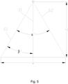
- Fig. 5 is a schematic diagram showing the relationship between the angle of half intensity of the optical device provided by the present invention and the width of the planting area 3.
- the angle between the first light ray of half intensity 61 of the optical device provided by the present invention and the second light ray of half intensity 62 of the optical device 1 provided by the present invention is ⁇ .
- H is the vertical height from the LED lamp 1 of the optical device provided by the present invention to the planting area
- W is the width of the planting area.
- the reflector 2 provided by the embodiment of the present invention can reflect the side light with a luminous intensity less than that of the central light ray 11 to the planting area 3, as shown in Fig. 6 , thereby reducing light waste.
- the first curve 6 is the light distribution curve of the LED lamp 1 without the reflector 2.
- the second curve 7 is the light distribution curve of the plant illumination optical device provided by this embodiment. It can be known that the plant illumination optical device provided by this embodiment can significantly improve the illumination uniformity of the planting area 3.
- the plant illumination optical device provided by this embodiment can be used to illuminate plants in a close range, thereby saving planting space and increasing planting area by providing more layers of planting areas within a unit height. Moreover, the out-of-edge light ray can be reflected back to the planting area. Further, the out-of-edge light ray can be reflected to the area with relatively weak luminous intensity in the planting area.
- the plant illumination optical device includes two LED lamp bodies.
- a cross section of the plant illumination optical device has two LED lamps 1 and two reflectors 2.
- the two LED lamps 1 are respectively configured at the center position of the inner side of the two reflectors 2.
- the two reflectors 2 are symmetrically placed above the centerline of the planting area 3. Namely, in this embodiment, two LED lamp bodies of the plant illumination optical device provided by the previous embodiment are symmetrically arranged above the centerline of the planting area 3.
- the reflectors 2 in this embodiment can be implemented by referring to the previous embodiment and are not repeated here again.
- the angle A between the two reflectors 2 can be adjusted according to the width of the planting area and the height of the LED lamps. Namely, the angle between the central light rays of the two LED lamp bodies can be adjusted. In order to reduce the light that irradiates outside the planting area while ensure the illumination uniformity in the planting area, under a condition of defined installation height and planting width, an optimum illumination effect can be achieved by adjusting the angle A within the range from 0° to 20°.
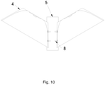
- the LED lamp 1 and the reflector 2 are fixed in a housing 4.
- the housing 4 has an opening which allows the light emitted from the LED lamp 1 and the light reflected by the reflector 2 to pass.
- the housing 4 is fixed on a support 5.
- the housing 4 can be fixed on one side of the support 5 by an angle adjustable mechanism.
- the housing 4 is fixed on the support 5 by screws 8.
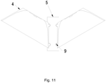
- the housing 4 is fixed on the support through a ball fastening connection 9 and an end cover threaded connection.
- the housing 4 is fixed on the support 5 through the push-pull assembly 10 and adhesive.
- the housing 4 may also be fixed on one side of an angle adjustable support.
- the LED lamp and the reflector are respectively fixed on the two supports through the housing, and the two supports can rotate relatively to form angle adjustable supports, so as to facilitate the adjustment of the angle A.
- the advantages of the plant illumination optical device provided in this embodiment may be shown in Figs. 13 and 14 .
- the third curve 11 is the light distribution curve of the plant illumination optical device provided in this embodiment. It can be known that the plant illumination optical device provided by this embodiment can significantly improve the illumination uniformity of the planting area 3.
- the plant illumination optical device provided by this embodiment can be used to illuminate plants in a close range, so as to save planting space and increase planting area by providing more layers of planting areas within a unit height. Moreover, the out-of-edge light ray can be reflected back to the planting area. Further, the out-of-edge light ray can be reflected to the area with relatively weak luminous intensity in the planting area.
- the plant illumination optical device includes two LED lamp bodies, and each LED lamp body includes an LED lamp 1 (see Fig. 2 ), a reflector 2 (see Fig. 2 ) and a lens (not shown).
- the LED lamp 1 is configured at the center position of the inner side of the reflector 2, and the lens is configured at the top end of the inner side of the reflector 2 and covers the light emitting surface of the LED lamp 1.
- the reflectors 2 can be implemented by referring to the foregoing embodiments and are not repeated here again.
- the arrangement of the two LED lamp bodies can be implemented by referring to the foregoing embodiments and is not repeated here again.
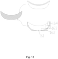
- the structure of the lens is shown in Fig. 15 .
- the inner side surface of the lens is concave and has the uniform curvature, so that the incident light has a uniform angular change after entering the lens and converges at the center.
- the outer side surface of the lens has a symmetrical structure.
- the central portion 161 has a negative curvature (which means that the central portion 161 is concave inward) and forms a concave lens in cooperation with the corresponding inner side surface. From the center portion to one end, there are three parts, i.e. a fourth segment 162, a fifth segment 163, and a sixth segment 164.
- the luminous intensity of the center is reduced, and the light is decentralized to the two sides from the center to increase the luminous intensities of the two sides.
- the curvature of the fourth segment 162 increases gradually, and has a function of a convex lens, which can converge the light on the sides.
- the curvature of the fifth segment 163 is first reduced and then increased, thereby adjusting the angle of the outgoing light, so that the corresponding position in the planting area 3 can uniformly receive the outgoing light here.
- the curvature of the sixth segment 164 decreases gradually, so that the side light emitted by the LED lamp 1 converges inward.
- the abscissa in Fig. 16 indicates the relative position of all the parts of the outer side surface of the lens, starting from one end (the abscissa of this end in Fig. 16 is 0) and ending at the other end (the abscissa of this end in Fig. 16 is 1).
- the ordinate in Fig. 4 represents the relative value of the curvature value corresponding to each point of the curve.
- the inner side surface of the lens is the surface facing the LED lamp 1
- the outer side surface of the lens is the surface facing away the LED lamp 1.
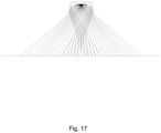
- the working principle of the plant illumination optical device provided by this embodiment is shown in Fig. 17 . It can be known that the plant illumination optical device provided by this embodiment can significantly improve the illumination uniformity of the planting area.
- the plant illumination optical device provided by this embodiment can be used to illuminate plants in a close range, thereby saving planting space and increasing planting area by providing more layers of planting areas within a unit height. Moreover, the out-of-edge light ray can be reflected back to the planting area. Further, the out-of-edge light ray can be reflected to the area with relatively weak luminous intensity in the planting area.
- the present invention can effectively overcome the various drawbacks in the prior art and has a high industrial utilization value.
Landscapes
- Engineering & Computer Science (AREA)
- General Engineering & Computer Science (AREA)
- Life Sciences & Earth Sciences (AREA)
- Environmental Sciences (AREA)
- Biodiversity & Conservation Biology (AREA)
- Botany (AREA)
- Ecology (AREA)
- Forests & Forestry (AREA)
- Cultivation Of Plants (AREA)
- Non-Portable Lighting Devices Or Systems Thereof (AREA)
Description
- The present invention relates to the field of plant illumination technology, and particularly to a plant illumination optical device and a plant cultivation device containing the optical device.
- At present, in the field of agriculture, economic efficiency can be improved through intensive planting, for example, making full use of the space to increase the planting area. The light source for plant illumination is one of the bottlenecks of intensive planting.
- Generally, the light source of the plant illumination optical device is a thermal source, such as a high voltage sodium lamp. The thermal source would cause severe infrared radiation and generate a large amount of heat, which not only consumes a lot of energy, but also leads to a low space utilization because it should be installed above the plants in a far distance to avoid the influence of the high temperature generated by the lamp on the plants.
- In addition, the plant illumination optical device available now no matter using high voltage sodium lamps or other thermal sources, has a problem that the central luminous intensity is stronger than the luminous intensity on both sides, and the luminous intensity distribution is uneven, thereby affecting the quality of plants.
- Some prior art references that may be relevant include
KR 100936942 -
CN 204534361 includes a kind of plant growth lamp. The lamp support body supports an LED light source, radiator and lamp bracket. Multiple photosynthetic lights can be included and red, blue, yellow LED and distribution may promote plant growth effectively. -
KR 20130056775 -
US 2012/218757 includes a lighting apparatus using light emitting diodes (LEDs) having a lateral heat radiation unit structure that can maximize heat radiation effect by employing an air vent structure causing atmospheric pressure difference between both side ends of an air circulation path. The lighting apparatus comprising a housing having a power supply accommodation space therein, a heat radiation unit that comprises an LED module accommodation groove that is installed on the top of the housing and having at least one inclined surface or mounting surface on which the LED module is mounted, and a number of fins that are formed on the outer circumferential surface of the LED module accommodation groove, an air circulation path that is lengthily formed between the housing and the heat radiation unit. -
US 2014/085880 A1 discloses a plant illumination optical device, characterized in that, comprising two LED lamp bodies; wherein each of the LED lamp bodies comprises: a reflector and a plurality of LED lamps forming a row along the length direction, located at an inner side of the reflector, wherein an angle between central light rays of the two LED lamp bodies is adjustable, and the LED lamp and the reflector are fixed on one side of an angle adjustable support through a housing apparatus. - In view of the above-mentioned drawbacks of the prior art, the objective of the present invention is to provide a plant illumination optical device, which can save planting space, reflect the light beyond the planting area back to the planting area, and can supplement the illumination on both sides of the centerline of the planting area, thereby reducing light waste, improving energy efficiency, and improving planting quality of the planting area.
- In the first aspect, the present invention provides a plant illumination optical device, including two LED lamp bodies. Each of the LED lamp bodies includes a reflector and an LED lamp located at an inner side of the reflector, and an angle between central light rays of the two LED lamp bodies is adjustable, wherein the LED lamp and the reflector are fixed on one side of an angle adjustable support through a housing and the reflector has a curved structure with two symmetrical sides, wherein each of the two sides comprises, starting from the LED lamp, a first segment, a second segment and a third segment from the highest reflection point to the lowest reflection point, wherein in the direction from the highest reflection point to the lowest reflection point, the curvature of the first segment gradually decreases, the curvature of the second segment variates from small to large and the curvature of the third segment variates from large to small.
- In an embodiment of the present invention, the angle between the central light rays of the two LED lamp bodies is in a range of 0°-20°.
- In an embodiment of the present invention, the LED lamp body further includes a lens; the lens is configured at an inner top end of the reflector and covers a light emitting surface of the LED lamp.
- In an embodiment of the present invention, the lens has a symmetrical structure.
- In the second aspect, the present invention provides a plant cultivation device containing the plant illumination optical device described in the first aspect.
- The plant illumination optical device and the plant cultivation device provided by the present invention can provide illumination for plants in a close range, which saves planting space, can reflect light beyond the planting area back to the planting area, and can supplement the illumination on both sides of the illumination centerline, thereby reducing light waste, improving energy efficiency, improving the uniformity of illumination in the planting area, and improving planting quality of the planting area.
-
-
Fig. 1 is a curve graph of light distribution when LED lamps are used alone. -
Fig. 2 is a schematic diagram showing a three-dimensional structure of a plant illumination optical device according to one embodiment of the present invention; -
Fig. 3 is a structural schematic diagram showing the cross section of the reflector shown inFig. 2 ; -
Fig. 4 is a schematic diagram showing the curvature variation of the reflector shown inFig. 2 ; -
Fig. 5 is a schematic diagram showing the relationship between the angle of half luminous intensity of the plant illumination optical device shown inFig. 2 and the width of the planting area; -
Fig. 6 is a schematic diagram showing the working principle of a plant illumination optical device according to one embodiment of the present invention; -
Fig. 7 is a comparison diagram of a light distribution curve of a plant illumination optical device and a light distribution curve of a LED lamp used alone according to one embodiment of the present invention; -
Fig. 8 is a diagram showing a luminous intensity of a light emitting surface of a plant illumination optical device according to one embodiment of the present invention; -
Fig. 9 is a schematic diagram showing an angle between two reflectors of a plant illumination optical device according to another embodiment of the present invention; -
Fig. 10 is a structural schematic diagram showing a front view of a plant illumination optical device according to another embodiment of the present invention; -
Fig. 11 is a structural schematic diagram showing a front view of an alternative implementation mode of the embodiment shown inFig 10 ; -
Fig. 12 is a structural schematic showing a front view of another alternative implementation mode of the embodiment shown inFig 10 ; -
Fig. 13 is a curve graph showing the light distribution of the plant illumination optical device shown inFig. 10 ; -
Fig. 14 is a diagram showing a luminous intensity of a light emitting surface of a plant illumination optical device shown inFig. 10 ; -
Fig. 15 is a structural schematic diagram of a lens of a plant illumination optical device according to yet another embodiment of the present invention; -
Fig. 16 is a schematic diagram showing the curvature variation of a side of the lens shown inFig. 15 facing away from the LED lamps; and -
Fig. 17 is a schematic diagram showing the working principle of a plant illumination optical device according to yet another embodiment of the present invention. - Before the embodiments of the present invention are further described, it should be understood that the protective scope of the present invention is not limited to the specific embodiments described below. It should also be understood that the terminologies used in the embodiments of the present invention are intended to describe particular specific embodiments, rather than limit the protective scope of the present invention. In the specification and claims of the present invention, the singular forms "an/a", "one", and "this/the" include the plural forms unless otherwise expressly stated in the context.
- When a numerical range is given in the embodiment, it should be understood that, unless otherwise specified in the present invention, two endpoints of every numerical range and any value falling within the two endpoints are acceptable. Unless otherwise defined, all technical and scientific terminologies used in the present invention have the same meaning as those commonly understood by those skilled in the art. In addition to the specific methods, devices and materials used in the embodiments, any methods, devices and materials available in the prior art similar or equivalent to the methods, devices and materials described in the embodiments of the present invention can be used to realize the present invention, according to the mastery of the prior art by those skilled in the art and the disclosure of the present invention.
- An LED lamp is a light source composed of one or more light emitting diodes (LEDs). LEDs can convert electrical energy into light energy. Therefore, the LED lamp is a cold light source which generates a small amount of heat, and can be used for plant illumination in a close distance, so as to save planting space. Further, by using the LED lamps, the planting area can be increased and the economic benefits for crop planting can be improved.
- The LED lamp 1 (see
Fig. 2 ) is small in size and can be approximately considered as a point light source with a large angle of half luminous intensity, also known as a Lambertian LED lamp. In other words, the optical properties of the LED lamp include the 180-degree light emitting and the strongest luminous intensity of the central light ray. The luminous intensity of the light rays on both sides are getting weaker with the increase of the angle. - In the absence of reflector 2, the light distribution curve of the LED lamp is shown in
Fig. 1 . InFig. 1 , the angle of thecentral light ray 11 of theLED lamp 1, i.e., the light ray perpendicular to the light emitting surface of the LED lamp, is 0°. The luminous intensity Iθ of thelight ray 12 of the Lambertian LED lamp with an angle of θ is equal to the luminous intensity I0 of thecentral light ray 11 of the Lambertian LED lamp multiplied by the cosine of the direction angle, that is, Iθ = I0 cos θ. - Obviously, if only LED lamps are used for plant illumination, there is a large difference in the luminous intensities received at different locations in the planting area 3 (see
Fig. 2 ). Generally, the plant illumination lamp is placed above the planting area 3 at the center or the centerline position, and the luminous intensity received at the center or centerline position of the planting area 3 is much greater than the luminous intensity received at the two sides, so that the yields of different plants in the planting area 3 are different, or the qualities are different, thereby affecting the economic benefits. - In addition, since the illumination angle of the
LED lamp 1 is relatively large, i.e. 180° or close to 180°, a part of the light rays emitted by theLED lamp 1 are irradiated at areas outside the planting area 3, and this part of the light rays is called out-of-edge light rays. The out-of-edge light rays cannot be used by the plants in the planting area 3, thereby causing light waste and low energy efficiency. - In view of the above situation, one embodiment of the present invention provides a plant illumination optical device. As shown in
Fig. 2 , the plant illumination optical device includes an LED lamp body, and the LED lamp body includes anLED lamp 1 and a reflector 2. The reflector 2 can reflect the out-of-edge light rays of theLED lamp 1 back to the planting area 3, so that the out-of-edge light rays can be utilized by the plants in the planting area 3. - The reflector 2 has a curved structure, and the path of the out-of-edge light ray are controlled by controlling the curvature and normal direction of the reflector 2 to reflect the out-of-edge light ray to the planting area 3. Further, by reflecting the out-of-edge light ray to the area of the planting area 3 with relatively weak luminous intensity, not only the light waste is reduced, but also the energy utilization rate is improved. Meanwhile, the illumination of the area of the planting area 3 with relatively weak light is enhanced, which allows the entire planting area 3 to receive a more uniform illumination, thereby enhancing the quality consistency of the plants in the planting area 3.
- In the plant illumination optical device shown in
Fig. 2 , the LED lamp body includes a plurality ofLED lamps 1. Moreover, the plurality ofLED lamps 1 are arranged in a row along the length direction. - The plant illumination optical device provided in this embodiment has an LED lamp body, and a cut surface of the plant illumination optical device has a
single LED lamp 1. TheLED lamp 1 is configured at an inner side of the reflector 2. Preferably, theLED lamp 1 is configured at the center position at the inner side of the reflector 2. TheLED lamp 1 is provided at a preset position above the center area or the centerline of the planting area 3, and the vertical distance from the preset position to the plants in the planting area 3 is H. The width of the planting area 3 is W, where H can be less than or equal to 1/2 W. - The structure of the reflector 2 according to the embodiment of the present invention will be described in detail with reference to
Figs. 3 and4 , hereinafter. - As shown in
Fig. 3 , the reflector 2 has a symmetrical structure, and the structure of one side of the reflector 2 will be introduced below. The structure of this side of the reflector 2 can be divided into afirst segment 41, asecond segment 42, and athird segment 43 from the highest reflection point to the lowest reflection point. In the direction from the highest reflection point to the lowest reflection point, the curvature of thefirst segment 41 gradually decreases, the curvature of thesecond segment 42 variates from small to large, and the curvature of thethird segment 43 variates from large to small.Fig. 4 is an example of specific variations in curvatures of thefirst segment 41, thesecond segment 42, and thethird segment 43. The abscissa inFig. 4 indicates the relative position of all the parts of the reflector 2, starting from one end (the abscissa of this end inFig. 4 is 0) and ending at the other end (the abscissa of this end inFig. 4 is 1). The ordinate inFig. 4 represents the relative value of the curvature value corresponding to each point of the curve. - The structure of the other side can be implemented with reference to above description.
- The outgoing light angle of the optical device provided by the present invention is an angle of light for which the luminous intensity is half that of the maximum luminous intensity at the center. Namely, extending from the central normal line of the light source to the surroundings, the angle between the position with half luminous intensity and the coordinate center is an angle of half intensity, also known as a beam angle.
-
Fig. 5 is a schematic diagram showing the relationship between the angle of half intensity of the optical device provided by the present invention and the width of the planting area 3. The angle between the first light ray ofhalf intensity 61 of the optical device provided by the present invention and the second light ray ofhalf intensity 62 of theoptical device 1 provided by the present invention is α. Obviously, the angle between the first light ray ofhalf intensity 61 or the second light ray ofhalf intensity 62 and the centerlight ray 11 is
LED lamp 1 of the optical device provided by the present invention to the planting area, and W is the width of the planting area. When H ∗ tan
central light ray 11 to the planting area 3, as shown inFig. 6 , thereby reducing light waste. - The advantages of the plant illumination optical device provided by this embodiment can be as shown in
Figs. 7 and8 . In the drawings, thefirst curve 6 is the light distribution curve of theLED lamp 1 without the reflector 2. Thesecond curve 7 is the light distribution curve of the plant illumination optical device provided by this embodiment. It can be known that the plant illumination optical device provided by this embodiment can significantly improve the illumination uniformity of the planting area 3. - The plant illumination optical device provided by this embodiment can be used to illuminate plants in a close range, thereby saving planting space and increasing planting area by providing more layers of planting areas within a unit height. Moreover, the out-of-edge light ray can be reflected back to the planting area. Further, the out-of-edge light ray can be reflected to the area with relatively weak luminous intensity in the planting area.
- Another embodiment of the present invention provides a plant illumination optical device. The plant illumination optical device includes two LED lamp bodies. A cross section of the plant illumination optical device has two
LED lamps 1 and two reflectors 2. The twoLED lamps 1 are respectively configured at the center position of the inner side of the two reflectors 2. The two reflectors 2 are symmetrically placed above the centerline of the planting area 3. Namely, in this embodiment, two LED lamp bodies of the plant illumination optical device provided by the previous embodiment are symmetrically arranged above the centerline of the planting area 3. - The reflectors 2 in this embodiment can be implemented by referring to the previous embodiment and are not repeated here again.
- As shown in
Fig. 9 , the angle A between the two reflectors 2 can be adjusted according to the width of the planting area and the height of the LED lamps. Namely, the angle between the central light rays of the two LED lamp bodies can be adjusted. In order to reduce the light that irradiates outside the planting area while ensure the illumination uniformity in the planting area, under a condition of defined installation height and planting width, an optimum illumination effect can be achieved by adjusting the angle A within the range from 0° to 20°. - The
LED lamp 1 and the reflector 2 are fixed in ahousing 4. Specifically, thehousing 4 has an opening which allows the light emitted from theLED lamp 1 and the light reflected by the reflector 2 to pass. Thehousing 4 is fixed on asupport 5. Specifically, thehousing 4 can be fixed on one side of thesupport 5 by an angle adjustable mechanism. As shown inFig. 10 , thehousing 4 is fixed on thesupport 5 byscrews 8. Also, as shown inFig. 11 , thehousing 4 is fixed on the support through aball fastening connection 9 and an end cover threaded connection. As shown inFig. 12 , thehousing 4 is fixed on thesupport 5 through the push-pull assembly 10 and adhesive. Thehousing 4 may also be fixed on one side of an angle adjustable support. As shown inFig. 9 , the LED lamp and the reflector are respectively fixed on the two supports through the housing, and the two supports can rotate relatively to form angle adjustable supports, so as to facilitate the adjustment of the angle A. - The advantages of the plant illumination optical device provided in this embodiment may be shown in
Figs. 13 and14 . Thethird curve 11 is the light distribution curve of the plant illumination optical device provided in this embodiment. It can be known that the plant illumination optical device provided by this embodiment can significantly improve the illumination uniformity of the planting area 3. - The plant illumination optical device provided by this embodiment can be used to illuminate plants in a close range, so as to save planting space and increase planting area by providing more layers of planting areas within a unit height. Moreover, the out-of-edge light ray can be reflected back to the planting area. Further, the out-of-edge light ray can be reflected to the area with relatively weak luminous intensity in the planting area.
- Yet, another embodiment of the present invention provides a plant illumination optical device. The plant illumination optical device includes two LED lamp bodies, and each LED lamp body includes an LED lamp 1 (see
Fig. 2 ), a reflector 2 (seeFig. 2 ) and a lens (not shown). TheLED lamp 1 is configured at the center position of the inner side of the reflector 2, and the lens is configured at the top end of the inner side of the reflector 2 and covers the light emitting surface of theLED lamp 1. - The reflectors 2 can be implemented by referring to the foregoing embodiments and are not repeated here again.
- The arrangement of the two LED lamp bodies can be implemented by referring to the foregoing embodiments and is not repeated here again.
- The structure of the lens is shown in
Fig. 15 . The inner side surface of the lens is concave and has the uniform curvature, so that the incident light has a uniform angular change after entering the lens and converges at the center. The outer side surface of the lens has a symmetrical structure. Thecentral portion 161 has a negative curvature (which means that thecentral portion 161 is concave inward) and forms a concave lens in cooperation with the corresponding inner side surface. From the center portion to one end, there are three parts, i.e. afourth segment 162, afifth segment 163, and asixth segment 164. By forming a concave lens on the center of the outer side surface of the lens, the luminous intensity of the center is reduced, and the light is decentralized to the two sides from the center to increase the luminous intensities of the two sides. From thecenter portion 161 to one end, the curvature of thefourth segment 162 increases gradually, and has a function of a convex lens, which can converge the light on the sides. The curvature of thefifth segment 163 is first reduced and then increased, thereby adjusting the angle of the outgoing light, so that the corresponding position in the planting area 3 can uniformly receive the outgoing light here. The curvature of thesixth segment 164 decreases gradually, so that the side light emitted by theLED lamp 1 converges inward.Fig. 16 is an example showing the specific curvature variations of thecentral portion 161, thefourth segment 162, thefifth segment 163, and thesixth segment 164. The abscissa inFig. 16 indicates the relative position of all the parts of the outer side surface of the lens, starting from one end (the abscissa of this end inFig. 16 is 0) and ending at the other end (the abscissa of this end inFig. 16 is 1). The ordinate inFig. 4 represents the relative value of the curvature value corresponding to each point of the curve. - In this embodiment, the inner side surface of the lens is the surface facing the
LED lamp 1, and the outer side surface of the lens is the surface facing away theLED lamp 1. - The working principle of the plant illumination optical device provided by this embodiment is shown in
Fig. 17 . It can be known that the plant illumination optical device provided by this embodiment can significantly improve the illumination uniformity of the planting area. - The plant illumination optical device provided by this embodiment can be used to illuminate plants in a close range, thereby saving planting space and increasing planting area by providing more layers of planting areas within a unit height. Moreover, the out-of-edge light ray can be reflected back to the planting area. Further, the out-of-edge light ray can be reflected to the area with relatively weak luminous intensity in the planting area.
- In summary, the present invention can effectively overcome the various drawbacks in the prior art and has a high industrial utilization value.
- The above-described embodiments merely exemplify the principles and functions of the present invention and are not intended to limit the present invention.
Claims (6)
- A plant illumination optical device comprising two LED lamp bodies; wherein each of the LED lamp bodies comprises: a reflector (2) and a plurality of LED lamps (1), wherein the plurality of LED lamps forms a row along the length direction, located at an inner side of the reflector (2), wherein an angle between central light rays of the two LED lamp bodies is adjustable, wherein the LED lamp (1) and the reflector (2) are fixed on one side of an angle adjustable support through a housing (4),
characterized in that:
the reflector has a curved structure with two symmetrical sides, wherein each of the two sides comprises, starting from the LED lamp, a first segment (41), a second segment (42) and a third segment (43) from the highest reflection point to the lowest reflection point, wherein in the direction from the highest reflection point to the lowest reflection point, the curvature of the first segment gradually decreases, the curvature of the second segment variates from small to large and the curvature of the third segment variates from large to small - The plant illumination optical device according to claim 1, characterized in that, the angle between the central light rays of the two LED lamps is in a range of 0°-20 °.
- The plant illumination optical device according to claim 1, characterized in that, each of the two LED lamp bodies further comprises a lens, wherein the lens is configured at a top end of the inner side of the reflector (2) and covers a light emitting surface of the LED lamp (1) and wherein the lamp has a lens with a concave central portion (161) on the exterior surface.
- The plant illumination optical device according to claim 3, characterized in that, the lens has a symmetrical structure.
- The plant illumination optical device according to claim 1, wherein the housing has the option to be fixed on one side of the support by an angle adjustable mechanism.
- A plant cultivation device, characterized in that, comprising the plant illumination optical device of any one of claims 1-5.
Applications Claiming Priority (2)
| Application Number | Priority Date | Filing Date | Title |
|---|---|---|---|
| CN201810154596.9A CN108224247B (en) | 2018-02-13 | 2018-02-23 | Optical device for plant illumination and plant cultivation device including the same |
| PCT/CN2018/123386 WO2019161706A1 (en) | 2018-02-23 | 2018-12-25 | Optical apparatus for plant illumination and plant cultivation apparatus comprising said optical apparatus |
Publications (3)
| Publication Number | Publication Date |
|---|---|
| EP3557119A1 EP3557119A1 (en) | 2019-10-23 |
| EP3557119A4 EP3557119A4 (en) | 2020-01-01 |
| EP3557119B1 true EP3557119B1 (en) | 2022-03-02 |
Family
ID=67437332
Family Applications (1)
| Application Number | Title | Priority Date | Filing Date |
|---|---|---|---|
| EP18882264.7A Active EP3557119B1 (en) | 2018-02-23 | 2018-12-25 | Optical apparatus for plant illumination and plant cultivation apparatus comprising said optical apparatus |
Country Status (4)
| Country | Link |
|---|---|
| US (1) | US10932419B2 (en) |
| EP (1) | EP3557119B1 (en) |
| CA (1) | CA3044284C (en) |
| WO (1) | WO2019161706A1 (en) |
Families Citing this family (4)
| Publication number | Priority date | Publication date | Assignee | Title |
|---|---|---|---|---|
| CN111602533B (en) * | 2020-05-18 | 2021-12-07 | 台州市路桥万驰机械厂 | Novel light filling lamps and lanterns are used in scene are made to plant |
| CN113141908B (en) * | 2021-05-11 | 2022-08-16 | 深圳市西地科技有限公司 | Free combination LED plant light filling lamp for cultivation room |
| CN114565846A (en) * | 2022-02-24 | 2022-05-31 | 杭州睿胜软件有限公司 | Plant growing environment identification method and equipment and computer readable storage medium |
| CN118900478B (en) * | 2024-09-04 | 2025-08-05 | 深圳市华亚光电科技有限公司 | Energy-saving light-emitting diode plant lighting lamp and dimming control method thereof |
Family Cites Families (14)
| Publication number | Priority date | Publication date | Assignee | Title |
|---|---|---|---|---|
| KR100936942B1 (en) * | 2009-04-16 | 2010-01-14 | 주식회사 정광테크 | Prefabricated led lighting equipment |
| KR101112661B1 (en) | 2009-11-05 | 2012-02-15 | 주식회사 아모럭스 | Lighting device using light emitting diode |
| JP5899508B2 (en) * | 2011-04-28 | 2016-04-06 | パナソニックIpマネジメント株式会社 | LIGHT EMITTING DEVICE AND LIGHTING DEVICE USING THE SAME |
| KR20130136572A (en) * | 2011-05-27 | 2013-12-12 | 가부시키가이샤 킬트플래닝오피스 | Lighting device |
| WO2013049619A1 (en) * | 2011-09-29 | 2013-04-04 | Titaness Light Shop, LLC | Luminaire for indoor horticulture |
| KR101353082B1 (en) * | 2011-11-22 | 2014-01-17 | 대한민국 | Rotary LED lighting system for plant growth regulation |
| CN202532279U (en) * | 2012-05-03 | 2012-11-14 | 中国计量学院 | Light emitting diode (LED) plant light-compensating lamp with adjustable irradiation angles and height |
| US20150260384A1 (en) * | 2014-03-11 | 2015-09-17 | Elb Electronics, Inc. | Fluorescent lamp fixture with leds |
| CN204534361U (en) * | 2015-04-21 | 2015-08-05 | 光曦(北京)光电科技有限公司 | A kind of plant growth lamp |
| US9574738B2 (en) * | 2015-05-28 | 2017-02-21 | Hon Hai Precision Industry Co., Ltd. | Lens, light emitting device and backlight module |
| CN205299391U (en) * | 2015-11-28 | 2016-06-08 | 陈国涛 | LED plant lamp with heat dissipation and waste heat recovery function |
| CN106545788B (en) * | 2016-11-24 | 2023-06-02 | 中国科学技术大学先进技术研究院 | High evenness light matter is than adjustable vegetation lamp |
| CN207880600U (en) * | 2018-02-13 | 2018-09-18 | 福建省中科生物股份有限公司 | Plant illumination Optical devices and plant cultivating device comprising the Optical devices |
| CN108534007B (en) * | 2018-02-13 | 2021-12-07 | 福建省中科生物股份有限公司 | Optical device for plant illumination and plant cultivation device including the same |
-
2018
- 2018-12-25 WO PCT/CN2018/123386 patent/WO2019161706A1/en not_active Ceased
- 2018-12-25 EP EP18882264.7A patent/EP3557119B1/en active Active
- 2018-12-25 US US16/349,977 patent/US10932419B2/en active Active
- 2018-12-25 CA CA3044284A patent/CA3044284C/en active Active
Also Published As
| Publication number | Publication date |
|---|---|
| US20200260652A1 (en) | 2020-08-20 |
| EP3557119A4 (en) | 2020-01-01 |
| US10932419B2 (en) | 2021-03-02 |
| WO2019161706A1 (en) | 2019-08-29 |
| CA3044284C (en) | 2021-08-03 |
| EP3557119A1 (en) | 2019-10-23 |
| CA3044284A1 (en) | 2019-08-23 |
Similar Documents
| Publication | Publication Date | Title |
|---|---|---|
| RU2459142C1 (en) | Street lamp based on light diodes | |
| US7581855B2 (en) | Apparatus and method for improved illumination area fill | |
| CN102759056B (en) | Vehicular lamp | |
| US20070247856A1 (en) | Lighting unit reflector | |
| CA3044284C (en) | Plant illumination optical device and plant cultivation device containing optical device | |
| EP3754248B1 (en) | Optical element and lighting lamp with the same | |
| US20140111986A1 (en) | Luminaire | |
| JP6539665B2 (en) | Sports lighting equipment | |
| KR100936942B1 (en) | Prefabricated led lighting equipment | |
| CN210992647U (en) | L ED array irradiator of phototherapy device | |
| JPWO2009028090A1 (en) | Light emitting device for lighting | |
| IL266744B (en) | An optical device for lighting a plant and a plant care device that includes an optical device | |
| US20100321935A1 (en) | Light source unit and illumination device | |
| US8360605B2 (en) | LED luminaire | |
| EP1533774B1 (en) | Signal lamp | |
| JP5950198B2 (en) | lighting equipment | |
| CN217603959U (en) | Thin anti-dazzle down lamp | |
| US8956008B2 (en) | Light-emitting unit and luminaire | |
| JP5723985B2 (en) | Lighting module with optimized radiation, especially for road lighting | |
| US9671083B2 (en) | Light fixture with reflective optics | |
| CN113446542B (en) | Stage lamp is with anti-dazzle mesh system | |
| CN218295471U (en) | Remote searchlight with floodlight | |
| TWI795896B (en) | Light emitting device | |
| JP2018055831A (en) | Lighting device | |
| JP2018055827A (en) | Lighting device |
Legal Events
| Date | Code | Title | Description |
|---|---|---|---|
| STAA | Information on the status of an ep patent application or granted ep patent |
Free format text: STATUS: UNKNOWN |
|
| STAA | Information on the status of an ep patent application or granted ep patent |
Free format text: STATUS: THE INTERNATIONAL PUBLICATION HAS BEEN MADE |
|
| PUAI | Public reference made under article 153(3) epc to a published international application that has entered the european phase |
Free format text: ORIGINAL CODE: 0009012 |
|
| STAA | Information on the status of an ep patent application or granted ep patent |
Free format text: STATUS: REQUEST FOR EXAMINATION WAS MADE |
|
| 17P | Request for examination filed |
Effective date: 20190522 |
|
| AK | Designated contracting states |
Kind code of ref document: A1 Designated state(s): AL AT BE BG CH CY CZ DE DK EE ES FI FR GB GR HR HU IE IS IT LI LT LU LV MC MK MT NL NO PL PT RO RS SE SI SK SM TR |
|
| AX | Request for extension of the european patent |
Extension state: BA ME |
|
| R17P | Request for examination filed (corrected) |
Effective date: 20190522 |
|
| A4 | Supplementary search report drawn up and despatched |
Effective date: 20191128 |
|
| RIC1 | Information provided on ipc code assigned before grant |
Ipc: F21V 13/04 20060101ALI20191122BHEP Ipc: F21V 21/30 20060101ALI20191122BHEP Ipc: F21S 2/00 20160101ALI20191122BHEP Ipc: F21Y 103/10 20160101ALI20191122BHEP Ipc: F21Y 115/10 20160101ALI20191122BHEP Ipc: F21S 8/00 20060101AFI20191122BHEP Ipc: A01G 7/04 20060101ALI20191122BHEP Ipc: F21V 19/02 20060101ALI20191122BHEP |
|
| STAA | Information on the status of an ep patent application or granted ep patent |
Free format text: STATUS: EXAMINATION IS IN PROGRESS |
|
| 17Q | First examination report despatched |
Effective date: 20200616 |
|
| DAV | Request for validation of the european patent (deleted) | ||
| DAX | Request for extension of the european patent (deleted) | ||
| GRAP | Despatch of communication of intention to grant a patent |
Free format text: ORIGINAL CODE: EPIDOSNIGR1 |
|
| STAA | Information on the status of an ep patent application or granted ep patent |
Free format text: STATUS: GRANT OF PATENT IS INTENDED |
|
| INTG | Intention to grant announced |
Effective date: 20211126 |
|
| GRAS | Grant fee paid |
Free format text: ORIGINAL CODE: EPIDOSNIGR3 |
|
| GRAA | (expected) grant |
Free format text: ORIGINAL CODE: 0009210 |
|
| STAA | Information on the status of an ep patent application or granted ep patent |
Free format text: STATUS: THE PATENT HAS BEEN GRANTED |
|
| AK | Designated contracting states |
Kind code of ref document: B1 Designated state(s): AL AT BE BG CH CY CZ DE DK EE ES FI FR GB GR HR HU IE IS IT LI LT LU LV MC MK MT NL NO PL PT RO RS SE SI SK SM TR |
|
| REG | Reference to a national code |
Ref country code: GB Ref legal event code: FG4D |
|
| REG | Reference to a national code |
Ref country code: CH Ref legal event code: EP Ref country code: AT Ref legal event code: REF Ref document number: 1472524 Country of ref document: AT Kind code of ref document: T Effective date: 20220315 |
|
| REG | Reference to a national code |
Ref country code: DE Ref legal event code: R096 Ref document number: 602018031803 Country of ref document: DE |
|
| REG | Reference to a national code |
Ref country code: IE Ref legal event code: FG4D |
|
| REG | Reference to a national code |
Ref country code: NL Ref legal event code: FP |
|
| REG | Reference to a national code |
Ref country code: LT Ref legal event code: MG9D |
|
| PG25 | Lapsed in a contracting state [announced via postgrant information from national office to epo] |
Ref country code: SE Free format text: LAPSE BECAUSE OF FAILURE TO SUBMIT A TRANSLATION OF THE DESCRIPTION OR TO PAY THE FEE WITHIN THE PRESCRIBED TIME-LIMIT Effective date: 20220302 Ref country code: RS Free format text: LAPSE BECAUSE OF FAILURE TO SUBMIT A TRANSLATION OF THE DESCRIPTION OR TO PAY THE FEE WITHIN THE PRESCRIBED TIME-LIMIT Effective date: 20220302 Ref country code: NO Free format text: LAPSE BECAUSE OF FAILURE TO SUBMIT A TRANSLATION OF THE DESCRIPTION OR TO PAY THE FEE WITHIN THE PRESCRIBED TIME-LIMIT Effective date: 20220602 Ref country code: LT Free format text: LAPSE BECAUSE OF FAILURE TO SUBMIT A TRANSLATION OF THE DESCRIPTION OR TO PAY THE FEE WITHIN THE PRESCRIBED TIME-LIMIT Effective date: 20220302 Ref country code: HR Free format text: LAPSE BECAUSE OF FAILURE TO SUBMIT A TRANSLATION OF THE DESCRIPTION OR TO PAY THE FEE WITHIN THE PRESCRIBED TIME-LIMIT Effective date: 20220302 Ref country code: ES Free format text: LAPSE BECAUSE OF FAILURE TO SUBMIT A TRANSLATION OF THE DESCRIPTION OR TO PAY THE FEE WITHIN THE PRESCRIBED TIME-LIMIT Effective date: 20220302 Ref country code: BG Free format text: LAPSE BECAUSE OF FAILURE TO SUBMIT A TRANSLATION OF THE DESCRIPTION OR TO PAY THE FEE WITHIN THE PRESCRIBED TIME-LIMIT Effective date: 20220602 |
|
| REG | Reference to a national code |
Ref country code: AT Ref legal event code: MK05 Ref document number: 1472524 Country of ref document: AT Kind code of ref document: T Effective date: 20220302 |
|
| PG25 | Lapsed in a contracting state [announced via postgrant information from national office to epo] |
Ref country code: PL Free format text: LAPSE BECAUSE OF FAILURE TO SUBMIT A TRANSLATION OF THE DESCRIPTION OR TO PAY THE FEE WITHIN THE PRESCRIBED TIME-LIMIT Effective date: 20220302 Ref country code: LV Free format text: LAPSE BECAUSE OF FAILURE TO SUBMIT A TRANSLATION OF THE DESCRIPTION OR TO PAY THE FEE WITHIN THE PRESCRIBED TIME-LIMIT Effective date: 20220302 Ref country code: GR Free format text: LAPSE BECAUSE OF FAILURE TO SUBMIT A TRANSLATION OF THE DESCRIPTION OR TO PAY THE FEE WITHIN THE PRESCRIBED TIME-LIMIT Effective date: 20220603 Ref country code: FI Free format text: LAPSE BECAUSE OF FAILURE TO SUBMIT A TRANSLATION OF THE DESCRIPTION OR TO PAY THE FEE WITHIN THE PRESCRIBED TIME-LIMIT Effective date: 20220302 |
|
| PG25 | Lapsed in a contracting state [announced via postgrant information from national office to epo] |
Ref country code: SM Free format text: LAPSE BECAUSE OF FAILURE TO SUBMIT A TRANSLATION OF THE DESCRIPTION OR TO PAY THE FEE WITHIN THE PRESCRIBED TIME-LIMIT Effective date: 20220302 Ref country code: SK Free format text: LAPSE BECAUSE OF FAILURE TO SUBMIT A TRANSLATION OF THE DESCRIPTION OR TO PAY THE FEE WITHIN THE PRESCRIBED TIME-LIMIT Effective date: 20220302 Ref country code: RO Free format text: LAPSE BECAUSE OF FAILURE TO SUBMIT A TRANSLATION OF THE DESCRIPTION OR TO PAY THE FEE WITHIN THE PRESCRIBED TIME-LIMIT Effective date: 20220302 Ref country code: PT Free format text: LAPSE BECAUSE OF FAILURE TO SUBMIT A TRANSLATION OF THE DESCRIPTION OR TO PAY THE FEE WITHIN THE PRESCRIBED TIME-LIMIT Effective date: 20220704 Ref country code: EE Free format text: LAPSE BECAUSE OF FAILURE TO SUBMIT A TRANSLATION OF THE DESCRIPTION OR TO PAY THE FEE WITHIN THE PRESCRIBED TIME-LIMIT Effective date: 20220302 Ref country code: CZ Free format text: LAPSE BECAUSE OF FAILURE TO SUBMIT A TRANSLATION OF THE DESCRIPTION OR TO PAY THE FEE WITHIN THE PRESCRIBED TIME-LIMIT Effective date: 20220302 Ref country code: AT Free format text: LAPSE BECAUSE OF FAILURE TO SUBMIT A TRANSLATION OF THE DESCRIPTION OR TO PAY THE FEE WITHIN THE PRESCRIBED TIME-LIMIT Effective date: 20220302 |
|
| PG25 | Lapsed in a contracting state [announced via postgrant information from national office to epo] |
Ref country code: IS Free format text: LAPSE BECAUSE OF FAILURE TO SUBMIT A TRANSLATION OF THE DESCRIPTION OR TO PAY THE FEE WITHIN THE PRESCRIBED TIME-LIMIT Effective date: 20220702 Ref country code: AL Free format text: LAPSE BECAUSE OF FAILURE TO SUBMIT A TRANSLATION OF THE DESCRIPTION OR TO PAY THE FEE WITHIN THE PRESCRIBED TIME-LIMIT Effective date: 20220302 |
|
| REG | Reference to a national code |
Ref country code: DE Ref legal event code: R097 Ref document number: 602018031803 Country of ref document: DE |
|
| PLBE | No opposition filed within time limit |
Free format text: ORIGINAL CODE: 0009261 |
|
| STAA | Information on the status of an ep patent application or granted ep patent |
Free format text: STATUS: NO OPPOSITION FILED WITHIN TIME LIMIT |
|
| PG25 | Lapsed in a contracting state [announced via postgrant information from national office to epo] |
Ref country code: DK Free format text: LAPSE BECAUSE OF FAILURE TO SUBMIT A TRANSLATION OF THE DESCRIPTION OR TO PAY THE FEE WITHIN THE PRESCRIBED TIME-LIMIT Effective date: 20220302 |
|
| 26N | No opposition filed |
Effective date: 20221205 |
|
| PG25 | Lapsed in a contracting state [announced via postgrant information from national office to epo] |
Ref country code: SI Free format text: LAPSE BECAUSE OF FAILURE TO SUBMIT A TRANSLATION OF THE DESCRIPTION OR TO PAY THE FEE WITHIN THE PRESCRIBED TIME-LIMIT Effective date: 20220302 |
|
| REG | Reference to a national code |
Ref country code: DE Ref legal event code: R119 Ref document number: 602018031803 Country of ref document: DE |
|
| PG25 | Lapsed in a contracting state [announced via postgrant information from national office to epo] |
Ref country code: IT Free format text: LAPSE BECAUSE OF FAILURE TO SUBMIT A TRANSLATION OF THE DESCRIPTION OR TO PAY THE FEE WITHIN THE PRESCRIBED TIME-LIMIT Effective date: 20220302 |
|
| REG | Reference to a national code |
Ref country code: CH Ref legal event code: PL |
|
| GBPC | Gb: european patent ceased through non-payment of renewal fee |
Effective date: 20221225 |
|
| REG | Reference to a national code |
Ref country code: BE Ref legal event code: MM Effective date: 20221231 |
|
| PG25 | Lapsed in a contracting state [announced via postgrant information from national office to epo] |
Ref country code: LU Free format text: LAPSE BECAUSE OF NON-PAYMENT OF DUE FEES Effective date: 20221225 |
|
| P01 | Opt-out of the competence of the unified patent court (upc) registered |
Effective date: 20230805 |
|
| PG25 | Lapsed in a contracting state [announced via postgrant information from national office to epo] |
Ref country code: LI Free format text: LAPSE BECAUSE OF NON-PAYMENT OF DUE FEES Effective date: 20221231 Ref country code: IE Free format text: LAPSE BECAUSE OF NON-PAYMENT OF DUE FEES Effective date: 20221225 Ref country code: GB Free format text: LAPSE BECAUSE OF NON-PAYMENT OF DUE FEES Effective date: 20221225 Ref country code: DE Free format text: LAPSE BECAUSE OF NON-PAYMENT OF DUE FEES Effective date: 20230701 Ref country code: CH Free format text: LAPSE BECAUSE OF NON-PAYMENT OF DUE FEES Effective date: 20221231 |
|
| PG25 | Lapsed in a contracting state [announced via postgrant information from national office to epo] |
Ref country code: FR Free format text: LAPSE BECAUSE OF NON-PAYMENT OF DUE FEES Effective date: 20221231 Ref country code: BE Free format text: LAPSE BECAUSE OF NON-PAYMENT OF DUE FEES Effective date: 20221231 |
|
| PG25 | Lapsed in a contracting state [announced via postgrant information from national office to epo] |
Ref country code: HU Free format text: LAPSE BECAUSE OF FAILURE TO SUBMIT A TRANSLATION OF THE DESCRIPTION OR TO PAY THE FEE WITHIN THE PRESCRIBED TIME-LIMIT; INVALID AB INITIO Effective date: 20181225 |
|
| PG25 | Lapsed in a contracting state [announced via postgrant information from national office to epo] |
Ref country code: CY Free format text: LAPSE BECAUSE OF FAILURE TO SUBMIT A TRANSLATION OF THE DESCRIPTION OR TO PAY THE FEE WITHIN THE PRESCRIBED TIME-LIMIT Effective date: 20220302 |
|
| PG25 | Lapsed in a contracting state [announced via postgrant information from national office to epo] |
Ref country code: MK Free format text: LAPSE BECAUSE OF FAILURE TO SUBMIT A TRANSLATION OF THE DESCRIPTION OR TO PAY THE FEE WITHIN THE PRESCRIBED TIME-LIMIT Effective date: 20220302 |
|
| PG25 | Lapsed in a contracting state [announced via postgrant information from national office to epo] |
Ref country code: MC Free format text: LAPSE BECAUSE OF FAILURE TO SUBMIT A TRANSLATION OF THE DESCRIPTION OR TO PAY THE FEE WITHIN THE PRESCRIBED TIME-LIMIT Effective date: 20220302 |
|
| PG25 | Lapsed in a contracting state [announced via postgrant information from national office to epo] |
Ref country code: MC Free format text: LAPSE BECAUSE OF FAILURE TO SUBMIT A TRANSLATION OF THE DESCRIPTION OR TO PAY THE FEE WITHIN THE PRESCRIBED TIME-LIMIT Effective date: 20220302 |
|
| PG25 | Lapsed in a contracting state [announced via postgrant information from national office to epo] |
Ref country code: MT Free format text: LAPSE BECAUSE OF FAILURE TO SUBMIT A TRANSLATION OF THE DESCRIPTION OR TO PAY THE FEE WITHIN THE PRESCRIBED TIME-LIMIT Effective date: 20220302 |
|
| PG25 | Lapsed in a contracting state [announced via postgrant information from national office to epo] |
Ref country code: TR Free format text: LAPSE BECAUSE OF FAILURE TO SUBMIT A TRANSLATION OF THE DESCRIPTION OR TO PAY THE FEE WITHIN THE PRESCRIBED TIME-LIMIT Effective date: 20220302 |
|
| PGFP | Annual fee paid to national office [announced via postgrant information from national office to epo] |
Ref country code: NL Payment date: 20251217 Year of fee payment: 8 |