EP3557008B1 - Aircraft engine with ice shedding system - Google Patents
Aircraft engine with ice shedding system Download PDFInfo
- Publication number
- EP3557008B1 EP3557008B1 EP19168266.5A EP19168266A EP3557008B1 EP 3557008 B1 EP3557008 B1 EP 3557008B1 EP 19168266 A EP19168266 A EP 19168266A EP 3557008 B1 EP3557008 B1 EP 3557008B1
- Authority
- EP
- European Patent Office
- Prior art keywords
- ice
- accumulating
- aircraft engine
- flange
- rotatable blade
- Prior art date
- Legal status (The legal status is an assumption and is not a legal conclusion. Google has not performed a legal analysis and makes no representation as to the accuracy of the status listed.)
- Active
Links
Images


Classifications
-
- F—MECHANICAL ENGINEERING; LIGHTING; HEATING; WEAPONS; BLASTING
- F01—MACHINES OR ENGINES IN GENERAL; ENGINE PLANTS IN GENERAL; STEAM ENGINES
- F01D—NON-POSITIVE DISPLACEMENT MACHINES OR ENGINES, e.g. STEAM TURBINES
- F01D25/00—Component parts, details, or accessories, not provided for in, or of interest apart from, other groups
- F01D25/02—De-icing means for engines having icing phenomena
-
- B—PERFORMING OPERATIONS; TRANSPORTING
- B64—AIRCRAFT; AVIATION; COSMONAUTICS
- B64D—EQUIPMENT FOR FITTING IN OR TO AIRCRAFT; FLIGHT SUITS; PARACHUTES; ARRANGEMENT OR MOUNTING OF POWER PLANTS OR PROPULSION TRANSMISSIONS IN AIRCRAFT
- B64D15/00—De-icing or preventing icing on exterior surfaces of aircraft
- B64D15/16—De-icing or preventing icing on exterior surfaces of aircraft by mechanical means, e.g. pulsating mats or shoes attached to, or built into, surface
-
- F—MECHANICAL ENGINEERING; LIGHTING; HEATING; WEAPONS; BLASTING
- F02—COMBUSTION ENGINES; HOT-GAS OR COMBUSTION-PRODUCT ENGINE PLANTS
- F02C—GAS-TURBINE PLANTS; AIR INTAKES FOR JET-PROPULSION PLANTS; CONTROLLING FUEL SUPPLY IN AIR-BREATHING JET-PROPULSION PLANTS
- F02C7/00—Features, components parts, details or accessories, not provided for in, or of interest apart form groups F02C1/00 - F02C6/00; Air intakes for jet-propulsion plants
-
- F—MECHANICAL ENGINEERING; LIGHTING; HEATING; WEAPONS; BLASTING
- F04—POSITIVE - DISPLACEMENT MACHINES FOR LIQUIDS; PUMPS FOR LIQUIDS OR ELASTIC FLUIDS
- F04D—NON-POSITIVE-DISPLACEMENT PUMPS
- F04D29/00—Details, component parts, or accessories
- F04D29/002—Details, component parts, or accessories especially adapted for elastic fluid pumps
-
- F—MECHANICAL ENGINEERING; LIGHTING; HEATING; WEAPONS; BLASTING
- F04—POSITIVE - DISPLACEMENT MACHINES FOR LIQUIDS; PUMPS FOR LIQUIDS OR ELASTIC FLUIDS
- F04D—NON-POSITIVE-DISPLACEMENT PUMPS
- F04D29/00—Details, component parts, or accessories
- F04D29/26—Rotors specially for elastic fluids
- F04D29/32—Rotors specially for elastic fluids for axial flow pumps
- F04D29/38—Blades
-
- F—MECHANICAL ENGINEERING; LIGHTING; HEATING; WEAPONS; BLASTING
- F04—POSITIVE - DISPLACEMENT MACHINES FOR LIQUIDS; PUMPS FOR LIQUIDS OR ELASTIC FLUIDS
- F04D—NON-POSITIVE-DISPLACEMENT PUMPS
- F04D29/00—Details, component parts, or accessories
- F04D29/70—Suction grids; Strainers; Dust separation; Cleaning
- F04D29/701—Suction grids; Strainers; Dust separation; Cleaning especially adapted for elastic fluid pumps
- F04D29/703—Suction grids; Strainers; Dust separation; Cleaning especially adapted for elastic fluid pumps specially for fans, e.g. fan guards
-
- B—PERFORMING OPERATIONS; TRANSPORTING
- B64—AIRCRAFT; AVIATION; COSMONAUTICS
- B64D—EQUIPMENT FOR FITTING IN OR TO AIRCRAFT; FLIGHT SUITS; PARACHUTES; ARRANGEMENT OR MOUNTING OF POWER PLANTS OR PROPULSION TRANSMISSIONS IN AIRCRAFT
- B64D33/00—Arrangement in aircraft of power plant parts or auxiliaries not otherwise provided for
- B64D33/02—Arrangement in aircraft of power plant parts or auxiliaries not otherwise provided for of combustion air intakes
- B64D2033/0233—Arrangement in aircraft of power plant parts or auxiliaries not otherwise provided for of combustion air intakes comprising de-icing means
-
- F—MECHANICAL ENGINEERING; LIGHTING; HEATING; WEAPONS; BLASTING
- F01—MACHINES OR ENGINES IN GENERAL; ENGINE PLANTS IN GENERAL; STEAM ENGINES
- F01D—NON-POSITIVE DISPLACEMENT MACHINES OR ENGINES, e.g. STEAM TURBINES
- F01D5/00—Blades; Blade-carrying members; Heating, heat-insulating, cooling or antivibration means on the blades or the members
- F01D5/12—Blades
- F01D5/14—Form or construction
- F01D5/147—Construction, i.e. structural features, e.g. of weight-saving hollow blades
-
- F—MECHANICAL ENGINEERING; LIGHTING; HEATING; WEAPONS; BLASTING
- F04—POSITIVE - DISPLACEMENT MACHINES FOR LIQUIDS; PUMPS FOR LIQUIDS OR ELASTIC FLUIDS
- F04D—NON-POSITIVE-DISPLACEMENT PUMPS
- F04D29/00—Details, component parts, or accessories
- F04D29/26—Rotors specially for elastic fluids
- F04D29/32—Rotors specially for elastic fluids for axial flow pumps
- F04D29/321—Rotors specially for elastic fluids for axial flow pumps for axial flow compressors
- F04D29/324—Blades
-
- F—MECHANICAL ENGINEERING; LIGHTING; HEATING; WEAPONS; BLASTING
- F05—INDEXING SCHEMES RELATING TO ENGINES OR PUMPS IN VARIOUS SUBCLASSES OF CLASSES F01-F04
- F05D—INDEXING SCHEME FOR ASPECTS RELATING TO NON-POSITIVE-DISPLACEMENT MACHINES OR ENGINES, GAS-TURBINES OR JET-PROPULSION PLANTS
- F05D2260/00—Function
- F05D2260/60—Fluid transfer
- F05D2260/607—Preventing clogging or obstruction of flow paths by dirt, dust, or foreign particles
Definitions
- the present disclosure relates generally to an aircraft engine, and more particularly to an aircraft engine subjected to ice buildup, having structures to facilitate the controlled shedding of the ice buildup.
- Aircraft engines are subjected to ice buildup under predetermined loads, pressures, and temperatures. This ice can often build up on rotating components which can adversely affect system dynamics by the increase of the ice mass. Further, because this ice buildup is often released unpredictably at times, and varying masses, the unbalancing of engine components can be thrown off leading to undesirable vibrations. It is an object of the invention to overcome these and other undesirable features.
- WO 2017/187073 discloses a propulsion system comprising a member in contact with a turbulent flow of a stream and covered at least partially with a structure grooved in the direction of fluid flow.
- an aircraft engine with the features of claim 1 configured to controllably shed ice during icing conditions is presented.
- the engine is subjected to ice buildup under predetermined loads, pressures, and temperatures.
- the engine has a member rotating at a first angular velocity about a rotational axis aligned with a flow direction.
- the member has a surface divided into an ice-accumulating surface configured to collect ice, and a shadow surface configured to resist the collection of ice.
- a flange is disposed between the ice accumulating surface and the shadow surface.
- the flange has an ice-accepting surface, which intersects the ice-accumulating surface and which together define an ice capturing volume proximate the ice-accumulating surface.
- the ice accepting surface and ice accumulating surface incrementally captures ice within the ice capturing volume from gasses passed through the engine.
- the predetermined mass of ice when a predetermined mass of ice is captured within the ice capturing volume, and the predetermined mass of ice is subjected to a first centrifugal force caused by rotation of the member, the predetermined mass of ice is subjected to shear stresses along an interface between the mass of ice and the member.
- the shear stress overcomes an adhesive force of the mass of ice, and the ice is shed from the ice-accumulating surface.
- the aircraft engine of the previous paragraphs can include a second flange disposed between a second ice accumulating surface and a second shadow surface.
- the second flange can have a second ice-accepting surface that intersects the second ice-accumulating surface that together define a second ice capturing volume above the second ice-accumulating surface which is smaller than the previously described ice-accumulating volume.
- the second ice accepting surface and second ice accumulating surface incrementally captures ice within the second ice capturing volume and shed the accumulated ice at a time which is different than the shedding of the previously described ice-accumulating volume.
- an aircraft engine as disclosed in claim 6 subjected to ice buildup includes a member rotating at a first angular velocity about a rotational axis transverse to the flow direction.
- the member has a surface divided into a first ice accumulating surface configured to collect ice, and a first shadow surface configured to resist the collection of ice.
- a generally V-shaped flange is disposed between the first ice accumulating surface and the first shadow surface.
- the generally V-shaped flange has a pair of ice accepting surfaces that intersect the first ice-accumulating surface and defines an ice capturing volume above the first ice-accumulating surface. The first ice accepting surface and first ice accumulating surface incrementally capture ice within the ice capturing volume.
- a first predetermined mass of ice is captured within the ice capturing volume and the predetermined mass of ice is subjected to a centrifugal force when the member is rotated about the rotational axis at the first angular velocity.
- the first predetermined mass of ice being subjected to releasing shear forces and shed from the first ice-accumulating surface when subjected to the centrifugal force caused by rotation of the mass of ice at the angular velocity.
- Propulsion system 10 includes an engine 12 covered by a nacelle 8 (nacelle 8 is transparent in FIG. 1 ).
- Engine 12 has rotatable blades or members 14 (as best seen in FIGS. 2-5 ) that are subjected to icing during flight.
- Nacelle 8 includes a cowl 13, the front end of which acts as an air intake, and which, under predetermined loads, pressures, and temperatures, facilitates the freezing of atmospheric water. As described below, this freezing atmospheric water is intentionally collected in a manner that will allow for the controlled shedding of ice to minimize the mass of ice shed.
- the nacelle 10 also includes an inlet module 15 and a nozzle module 17.
- a nacelle bypass 19 may be configured to bypass flow around the engine 12 from the inlet 15 to the nozzle 17.
- the rotatable blades 14 have flanges 16 that project generally perpendicular to the engine airflow and surfaces on the rotatable blade 14 to collect accumulated ice. As shown, these flanges 16 are positioned and sized in a manner that opposing blades within the engine will have the same configuration to allow simultaneous shedding of accumulated ice. As described below, by varying the height of the flanges 16 off the blade surface and radial position R of the flanges with respect to an axis of rotation of the blades C, allows an engineered timing of the release or shedding of varying masses of accumulated ice.
- the rotatable engine fan member 14 has the compression side surface divided into a first ice accumulating surface 20 configured to collect ice, and a first shadow surface 22 configured to resist or be shielded from the collection of ice by the flange.
- Fig. 3 represents a view of the rotatable engine fan member 14, which is rotating clockwise, shown in Figure 2 having the ice shedding features according to the present teachings.
- the rotatable engine fan member 14 is subjected to ice buildup under predetermined loads, pressures, and temperatures. Further, the rotatable engine fan member 14 is rotated at a first angular velocity about the axis of rotation of the blades C in a flow direction.
- This rotatable engine fan member 14 has a surface 18 divided into the first ice accumulating surface 20 configured to collect ice, and the shadow surface 22 configured to resist the collection of ice.
- a plurality of flanges 16 and 16' are disposed between the ice accumulating surfaces 20 and 20' and the shadow surfaces 22 and 22'. These flanges 16 and 16' can have varying heights and radial locations that can be located during the fan blade assembly 21 to adjust the amount and centroid location of ice accumulated. This adjusts the amount of centrifugal forces needed to shed the accumulated ice.
- the first flange has a first height and aspect ratio and a first axis X and second flange has a second height and aspect ratio and a second axis X'.
- the first axis and second axis can intersect, e.g. at about 90 degrees.
- the first and second axis can be parallel.
- the first ice-accepting surface 22 of the flange 16 can be generally perpendicular or angled to the rotational direction of the flange assembly 21
- V-shaped flanges 16 and 16' are disposed between the first and second ice accumulating surfaces 20 and 20' and the first and second shadow surfaces 22 and 22'.
- FIG 4 includes the positioning of two flanges 16 and 16' to form a V-shaped flange configuration.
- the first and second flanges 16 and 16' have ice accepting surfaces 26 and 26' which intersect the ice accumulating surfaces 20 and 20' to define ice capturing volumes 28 and 28' above the ice accumulating surfaces 20 and 20'.
- the second ice accepting surface 26' and second ice accumulating surface 20' incrementally capture ice within the second ice capturing volume 28'.
- a second predetermined mass of ice is captured within the second ice capturing volume 28' and the second predetermined mass of ice is subjected to a second centrifugal force.
- the second predetermined mass of ice is shed from the second ice-accumulating surface.
- the second ice accepting surface 26' and second ice accumulating surface 20' incrementally captures ice within the second ice capturing volume 28' and shed the accumulated ice at a time which is different than the shedding of the previously described ice-accumulating volume.
- the first volume of collected ice has a first centroid at a first radius from the axis of rotation of the blades C and the second volume of collected ice has a second centroid at a second radius from the axis of rotation of the blades C, the second radius being different than the first radius.
- Figures 5A and 5B represent sectional and top views of the rotatable member 14 shown in Figure 4 .
- the flange 16 has a first ice-accepting surface 22 that intersects the ice-accumulating surface 20 and defines the first ice capturing volume 28 above the ice-accumulating surface 20.
- Rotation of the rotatable engine fan member 14 causes the first ice accepting surface 22 and first ice accumulating surface 20 to incrementally capture ice within the first ice capturing volume 28.
- the generally V-shaped flange 16 is disposed between the first ice accumulating surface and the first shadow surface and has a pair of ice accepting surfaces which intersects the
- the predetermined mass of ice When a first predetermined mass of ice is captured within the ice capturing volume 28 and the predetermined mass of ice is subjected to a centrifugal force, the first predetermined mass of ice being shed from the first ice accumulating surface 20.
- the predetermined mass of ice is subjected to the first centrifugal force, the predetermined mass of ice is subjected to shear stresses along an interface between the mass of ice and the surfaces 20, 26. The shear stress overcomes an adhesive force of the mass of ice, and the ice is shed from the ice-accumulating surface.
- Example embodiments are provided so that this disclosure will be thorough, and will fully convey the scope to those who are skilled in the art. Numerous specific details are set forth such as examples of specific components, devices, and methods, to provide a thorough understanding of embodiments of the present disclosure. It will be apparent to those skilled in the art that specific details need not be employed, that example embodiments may be embodied in many different forms and that neither should be construed to limit the scope of the disclosure. In some example embodiments, well-known processes, well-known device structures, and well-known technologies are not described in detail.
- first, second, third, etc. may be used herein to describe various elements, components, regions, layers and/or sections, these elements, components, regions, layers and/or sections should not be limited by these terms. These terms may be only used to distinguish one element, component, region, layer or section from another region, layer or section. Terms such as “first,” “second,” and other numerical terms when used herein do not imply a sequence or order unless clearly indicated by the context. Thus, a first element, component, region, layer or section discussed below could be termed a second element, component, region, layer or section without departing from the teachings of the example embodiments.
- spatially relative terms such as “inner,” “outer,” “beneath,” “below,” “lower,” “above,” “upper,” and the like, may be used herein for ease of description to describe one element or feature's relationship to another element(s) or feature(s) as illustrated in the figures.
- Spatially relative terms may be intended to encompass different orientations of the device in use or operation in addition to the orientation depicted in the figures. For example, if the device in the figures is turned over, elements described as “below” or “beneath” other elements or features would then be oriented “above” the other elements or features.
- the example term “below” can encompass both an orientation of above and below.
- the device may be otherwise oriented (rotated 90 degrees or at other orientations) and the spatially relative descriptors used herein interpreted accordingly.
Landscapes
- Engineering & Computer Science (AREA)
- Mechanical Engineering (AREA)
- General Engineering & Computer Science (AREA)
- Chemical & Material Sciences (AREA)
- Combustion & Propulsion (AREA)
- Aviation & Aerospace Engineering (AREA)
- Structures Of Non-Positive Displacement Pumps (AREA)
Description
- The present disclosure relates generally to an aircraft engine, and more particularly to an aircraft engine subjected to ice buildup, having structures to facilitate the controlled shedding of the ice buildup.
- This section provides background information related to the present disclosure that is not necessarily prior art. Aircraft engines are subjected to ice buildup under predetermined loads, pressures, and temperatures. This ice can often build up on rotating components which can adversely affect system dynamics by the increase of the ice mass. Further, because this ice buildup is often released unpredictably at times, and varying masses, the unbalancing of engine components can be thrown off leading to undesirable vibrations. It is an object of the invention to overcome these and other undesirable features.
-
WO 2017/187073 discloses a propulsion system comprising a member in contact with a turbulent flow of a stream and covered at least partially with a structure grooved in the direction of fluid flow. - According to the present invention, an aircraft engine with the features of claim 1 configured to controllably shed ice during icing conditions is presented. The engine is subjected to ice buildup under predetermined loads, pressures, and temperatures. The engine has a member rotating at a first angular velocity about a rotational axis aligned with a flow direction. The member has a surface divided into an ice-accumulating surface configured to collect ice, and a shadow surface configured to resist the collection of ice. A flange is disposed between the ice accumulating surface and the shadow surface. The flange has an ice-accepting surface, which intersects the ice-accumulating surface and which together define an ice capturing volume proximate the ice-accumulating surface. The ice accepting surface and ice accumulating surface incrementally captures ice within the ice capturing volume from gasses passed through the engine.
- According to an alternate teaching, when a predetermined mass of ice is captured within the ice capturing volume, and the predetermined mass of ice is subjected to a first centrifugal force caused by rotation of the member, the predetermined mass of ice is subjected to shear stresses along an interface between the mass of ice and the member. The shear stress overcomes an adhesive force of the mass of ice, and the ice is shed from the ice-accumulating surface.
- According to an alternate teaching, the aircraft engine of the previous paragraphs can include a second flange disposed between a second ice accumulating surface and a second shadow surface. The second flange can have a second ice-accepting surface that intersects the second ice-accumulating surface that together define a second ice capturing volume above the second ice-accumulating surface which is smaller than the previously described ice-accumulating volume. The second ice accepting surface and second ice accumulating surface incrementally captures ice within the second ice capturing volume and shed the accumulated ice at a time which is different than the shedding of the previously described ice-accumulating volume.
- According to an alternative embodiment of the invention, an aircraft engine as disclosed in claim 6 subjected to ice buildup is presented. The engine includes a member rotating at a first angular velocity about a rotational axis transverse to the flow direction. The member has a surface divided into a first ice accumulating surface configured to collect ice, and a first shadow surface configured to resist the collection of ice. A generally V-shaped flange is disposed between the first ice accumulating surface and the first shadow surface. The generally V-shaped flange has a pair of ice accepting surfaces that intersect the first ice-accumulating surface and defines an ice capturing volume above the first ice-accumulating surface. The first ice accepting surface and first ice accumulating surface incrementally capture ice within the ice capturing volume.
- The aircraft engine according to the previous paragraph where a first predetermined mass of ice is captured within the ice capturing volume and the predetermined mass of ice is subjected to a centrifugal force when the member is rotated about the rotational axis at the first angular velocity. The first predetermined mass of ice being subjected to releasing shear forces and shed from the first ice-accumulating surface when subjected to the centrifugal force caused by rotation of the mass of ice at the angular velocity.
- Further areas of applicability will become apparent from the description provided herein. The description and specific examples in this summary are intended for purposes of illustration only and are not intended to limit the scope of the present disclosure.
- The drawings described herein are for illustrative purposes only of selected embodiments and not all possible implementations, and are not intended to limit the scope of the present disclosure.
-
FIG. 1 is a perspective view illustrating a nacelle having a non-limiting embodiment of an ice shedding engine according to the present invention; -
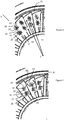
FIG. 2 is a a fragmented, axial view illustrating an engine fan of the ice shedding engine depicted inFIG. 1 ; -
FIG. 3 is an expanded, fragmented, axial view illustrating the engine fan shown inFIG. 2 having a non-limiting embodiment of the ice shedding features according to the present invention; -
FIG. 4 is a fragmented, axial view of the engine fan shown inFIG. 2 having another non-limiting embodiment of the ice shedding features according to the present invention; and -
FIGS. 5A and 5B are sectional and top views, respectively, illustrating the engine fan shown inFIG. 4 having the ice shedding features according to the present invention. - Corresponding reference numerals indicate corresponding parts throughout the several views of the drawings.
- Example embodiments will now be described more fully with reference to the accompanying drawings. The present disclosure will now be described more fully with reference to figures in which various embodiments of the invention are shown. The subject matter of this disclosure may, however, be embodied in many different forms and should not be construed as being limited to the embodiments set forth herein. While embodiments of the invention relate to engine configurations that include a bypass flow around the engine, an expanded design space may include other rotating engine components subjected to icing, and engines configured to travel at supersonic and subsonic speeds.
- Referring to
FIG. 1 , apropulsion system 10 is presented.Propulsion system 10 includes anengine 12 covered by a nacelle 8 (nacelle 8 is transparent inFIG. 1 ).Engine 12 has rotatable blades or members 14 (as best seen inFIGS. 2-5 ) that are subjected to icing during flight. Nacelle 8 includes acowl 13, the front end of which acts as an air intake, and which, under predetermined loads, pressures, and temperatures, facilitates the freezing of atmospheric water. As described below, this freezing atmospheric water is intentionally collected in a manner that will allow for the controlled shedding of ice to minimize the mass of ice shed. Further, the ice shedding in the engine is timed to shed ice in a manner that will decrease vibration due to offset masses from collected ice. Thenacelle 10 also includes aninlet module 15 and anozzle module 17. In accordance with embodiments of the invention, anacelle bypass 19 may be configured to bypass flow around theengine 12 from theinlet 15 to thenozzle 17. - As shown in
Fig. 2 , contrary to the traditional enginefan blade assembly 21, therotatable blades 14 haveflanges 16 that project generally perpendicular to the engine airflow and surfaces on therotatable blade 14 to collect accumulated ice. As shown, theseflanges 16 are positioned and sized in a manner that opposing blades within the engine will have the same configuration to allow simultaneous shedding of accumulated ice. As described below, by varying the height of theflanges 16 off the blade surface and radial position R of the flanges with respect to an axis of rotation of the blades C, allows an engineered timing of the release or shedding of varying masses of accumulated ice. The rotatableengine fan member 14 has the compression side surface divided into a firstice accumulating surface 20 configured to collect ice, and afirst shadow surface 22 configured to resist or be shielded from the collection of ice by the flange. -
Fig. 3 represents a view of the rotatableengine fan member 14, which is rotating clockwise, shown inFigure 2 having the ice shedding features according to the present teachings. The rotatableengine fan member 14 is subjected to ice buildup under predetermined loads, pressures, and temperatures. Further, the rotatableengine fan member 14 is rotated at a first angular velocity about the axis of rotation of the blades C in a flow direction. This rotatableengine fan member 14 has asurface 18 divided into the firstice accumulating surface 20 configured to collect ice, and theshadow surface 22 configured to resist the collection of ice. - A plurality of
flanges 16 and 16' are disposed between theice accumulating surfaces 20 and 20' and theshadow surfaces 22 and 22'. Theseflanges 16 and 16' can have varying heights and radial locations that can be located during thefan blade assembly 21 to adjust the amount and centroid location of ice accumulated. This adjusts the amount of centrifugal forces needed to shed the accumulated ice. - The first flange has a first height and aspect ratio and a first axis X and second flange has a second height and aspect ratio and a second axis X'. Optionally, the first axis and second axis can intersect, e.g. at about 90 degrees. Optionally, the first and second axis can be parallel. The first ice-accepting
surface 22 of theflange 16 can be generally perpendicular or angled to the rotational direction of theflange assembly 21 - As shown in
Figs 4-5B , V-shapedflanges 16 and 16' are disposed between the first and secondice accumulating surfaces 20 and 20' and the first and second shadow surfaces 22 and 22'.FIG 4 includes the positioning of twoflanges 16 and 16' to form a V-shaped flange configuration. The first andsecond flanges 16 and 16' haveice accepting surfaces 26 and 26' which intersect theice accumulating surfaces 20 and 20' to defineice capturing volumes 28 and 28' above theice accumulating surfaces 20 and 20'. As described above, the second ice accepting surface 26' and second ice accumulating surface 20' incrementally capture ice within the second ice capturing volume 28'. - A second predetermined mass of ice is captured within the second ice capturing volume 28' and the second predetermined mass of ice is subjected to a second centrifugal force. When the
fan blade 16 is rotating at the first angular velocity and the accumulating second ice mass reaches a critical predetermined value, the second predetermined mass of ice is shed from the second ice-accumulating surface. The second ice accepting surface 26' and second ice accumulating surface 20' incrementally captures ice within the second ice capturing volume 28' and shed the accumulated ice at a time which is different than the shedding of the previously described ice-accumulating volume. - Because of varying heights of the
flanges 16, 16', the first volume of collected ice has a first centroid at a first radius from the axis of rotation of the blades C and the second volume of collected ice has a second centroid at a second radius from the axis of rotation of the blades C, the second radius being different than the first radius. These differences can be used to tune the predetermined masses which will be shed for a given engine angular velocity. -
Figures 5A and 5B represent sectional and top views of therotatable member 14 shown inFigure 4 . Theflange 16 has a first ice-acceptingsurface 22 that intersects the ice-accumulatingsurface 20 and defines the firstice capturing volume 28 above the ice-accumulatingsurface 20. Rotation of the rotatableengine fan member 14 causes the firstice accepting surface 22 and firstice accumulating surface 20 to incrementally capture ice within the firstice capturing volume 28. The generally V-shapedflange 16 is disposed between the first ice accumulating surface and the first shadow surface and has a pair of ice accepting surfaces which intersects the - When a first predetermined mass of ice is captured within the
ice capturing volume 28 and the predetermined mass of ice is subjected to a centrifugal force, the first predetermined mass of ice being shed from the firstice accumulating surface 20. In this regard, and the predetermined mass of ice is subjected to the first centrifugal force, the predetermined mass of ice is subjected to shear stresses along an interface between the mass of ice and thesurfaces - Example embodiments are provided so that this disclosure will be thorough, and will fully convey the scope to those who are skilled in the art. Numerous specific details are set forth such as examples of specific components, devices, and methods, to provide a thorough understanding of embodiments of the present disclosure. It will be apparent to those skilled in the art that specific details need not be employed, that example embodiments may be embodied in many different forms and that neither should be construed to limit the scope of the disclosure. In some example embodiments, well-known processes, well-known device structures, and well-known technologies are not described in detail.
- The terminology used herein is for the purpose of describing particular example embodiments only and is not intended to be limiting. As used herein, the singular forms "a," "an," and "the" may be intended to include the plural forms as well, unless the context clearly indicates otherwise. The terms "comprises," "comprising," "including," and "having," are inclusive and therefore specify the presence of stated features, integers, steps, operations, elements, and/or components, but do not preclude the presence or addition of one or more other features, integers, steps, operations, elements, components, and/or groups thereof. The method steps, processes, and operations described herein are not to be construed as necessarily requiring their performance in the particular order discussed or illustrated, unless specifically identified as an order of performance. It is also to be understood that additional or alternative steps may be employed.
- When an element or layer is referred to as being "on," "engaged to," "connected to," or "coupled to" another element or layer, it may be directly on, engaged, connected or coupled to the other element or layer, or intervening elements or layers may be present. In contrast, when an element is referred to as being "directly on," "directly engaged to," "directly connected to," or "directly coupled to" another element or layer, there may be no intervening elements or layers present. Other words used to describe the relationship between elements should be interpreted in a like fashion (e.g., "between" versus "directly between," "adjacent" versus "directly adjacent," etc.). As used herein, the term "and/or" includes any and all combinations of one or more of the associated listed items.
- Although the terms first, second, third, etc. may be used herein to describe various elements, components, regions, layers and/or sections, these elements, components, regions, layers and/or sections should not be limited by these terms. These terms may be only used to distinguish one element, component, region, layer or section from another region, layer or section. Terms such as "first," "second," and other numerical terms when used herein do not imply a sequence or order unless clearly indicated by the context. Thus, a first element, component, region, layer or section discussed below could be termed a second element, component, region, layer or section without departing from the teachings of the example embodiments.
- Spatially relative terms, such as "inner," "outer," "beneath," "below," "lower," "above," "upper," and the like, may be used herein for ease of description to describe one element or feature's relationship to another element(s) or feature(s) as illustrated in the figures. Spatially relative terms may be intended to encompass different orientations of the device in use or operation in addition to the orientation depicted in the figures. For example, if the device in the figures is turned over, elements described as "below" or "beneath" other elements or features would then be oriented "above" the other elements or features. Thus, the example term "below" can encompass both an orientation of above and below. The device may be otherwise oriented (rotated 90 degrees or at other orientations) and the spatially relative descriptors used herein interpreted accordingly.
Claims (12)
- An aircraft engine (12) comprising:a rotatable blade (14) rotating at a first angular velocity about a rotational axis (C), the rotational axis aligned with a flow direction,characterized by:the rotatable blade having a surface (18) divided into a first ice-accumulating surface (20, 20') configured to collect ice, and a first shadow surface (22, 22') configured to resist the collection of ice;a first flange (16, 16') disposed between the first ice accumulating surface and the first shadow surface, the first flange having a first ice accepting surface (26, 26') which intersects the first ice accumulating surface and defines a first ice capturing volume (28, 28') above the first ice accumulating surface, wherein the first ice accepting surface and first ice accumulating surface are configured to incrementally capture ice within the first ice capturing volume.
- The aircraft engine according to Claim 1, wherein when the first flange is configured to capture the first predetermined mass of ice in the first ice capturing volume where the first predetermined mass of ice is subjected to a first centrifugal force when the rotatable blade is rotational rotating at the first angular velocity, the first predetermined mass of ice is shed from the first ice accumulating surface when subjected to the first centrifugal force.
- The aircraft engine according to Claim 1 or 2, wherein the rotatable blade surface is further divided into a second ice accumulating surface configured to collect a second ice mass, and a second shadow surface configured to resist exposure to ice accumulation, the rotatable blade surface further comprising a second flange disposed between the second ice accumulating surface and the second shadow surface, the second flange having a second ice accepting surface which intersects the second ice accumulating surface and defines a second ice capturing volume above the second ice accumulating surface, wherein the second ice accepting surface and second ice accumulating surface incrementally captures the second mass of ice within the second ice capturing volume.
- The aircraft engine according to Claim 3, wherein the second flange is configured to collect a second predetermined mass of ice which is captured within the second ice capturing volume and the second predetermined mass of ice is subjected to a second centrifugal force when the rotatable blade is operating at the first angular velocity the second predetermined mass of ice is shed from the first ice accumulating surface.
- The aircraft engine according to Claims 3 to 4, wherein the first mass of ice has a first centroid at a first radius from the rotational axis and the second mass of ice has a second centroid at a second radius from the rotational axis, the second radius being different than the first radius.
- An aircraft engine (12) comprising:a rotatable blade (14) operating at a first angular velocity about a rotation axis (C), the rotational axis aligned with a flow direction through the aircraft engine,characterized by:the rotatable blade having a compression side surface (18) divided into a first ice-accumulating surface (20, 20') configured to collect ice, and a first shadow surface (22, 22') configured to be shadowed from the collection of ice;a generally V-shaped flange (16, 16') disposed between the first ice accumulating surface and the first shadow surface, the generally V-shaped flange having a pair of ice accepting surfaces (26, 26') which intersects the first ice accumulating surface and defines an ice capturing volume (28, 28') above the first ice accumulating surface, wherein the first ice accepting surface and first ice accumulating surface are configured to incrementally capture a first predetermined mass of ice within the first ice capturing volume.
- The aircraft engine according to Claim 6, wherein when the first flange is configured to capture the first predetermined mass of ice in the first ice capturing volume where the first predetermined mass of ice is subjected to a first centrifugal force when the rotatable blade is rotational rotating at the first angular velocity, the first predetermined mass of ice is shed from the first ice accumulating surface when subjected to the first centrifugal force.
- The aircraft engine according to Claim 6 or 7, wherein the rotatable blade surface is generally planar and the V-shaped flange is perpendicular to the rotatable blade surface.
- The aircraft engine according to Claims 6 to 8, wherein the rotatable blade is a fan blade.
- The aircraft engine according to Claims 7 to 9, wherein the first predetermined mass of ice has a first centroid at a first radius from the rotational center.
- The aircraft engine according to Claims 6 to 10, further comprising a second V-shaped flange disposed on the compression side surface.
- The aircraft engine according to Claims 6 to 11, wherein the V-shaped flange has first and second legs that intersect at about 90 degrees.
Applications Claiming Priority (1)
| Application Number | Priority Date | Filing Date | Title |
|---|---|---|---|
| US201862654999P | 2018-04-09 | 2018-04-09 |
Publications (2)
| Publication Number | Publication Date |
|---|---|
| EP3557008A1 EP3557008A1 (en) | 2019-10-23 |
| EP3557008B1 true EP3557008B1 (en) | 2021-02-17 |
Family
ID=66103001
Family Applications (1)
| Application Number | Title | Priority Date | Filing Date |
|---|---|---|---|
| EP19168266.5A Active EP3557008B1 (en) | 2018-04-09 | 2019-04-09 | Aircraft engine with ice shedding system |
Country Status (3)
| Country | Link |
|---|---|
| US (1) | US11492923B2 (en) |
| EP (1) | EP3557008B1 (en) |
| CN (1) | CN110360163B (en) |
Families Citing this family (2)
| Publication number | Priority date | Publication date | Assignee | Title |
|---|---|---|---|---|
| CN114625159B (en) * | 2022-01-21 | 2023-07-28 | 中国空气动力研究与发展中心计算空气动力研究所 | A Control Method of Icing Aircraft Based on Controlled Variables |
| TWI871703B (en) * | 2023-07-19 | 2025-02-01 | 宏碁股份有限公司 | Axial-flow heat-dissipation fan |
Family Cites Families (18)
| Publication number | Priority date | Publication date | Assignee | Title |
|---|---|---|---|---|
| BE789482A (en) * | 1971-10-04 | 1973-01-15 | Gen Electric | CONSTRUCTION OF DE-ICING WHEEL FOR TURBOMACHINE |
| US4128363A (en) * | 1975-04-30 | 1978-12-05 | Kabushiki Kaisha Toyota Chuo Kenkyusho | Axial flow fan |
| DE3534293A1 (en) * | 1985-09-26 | 1987-04-02 | Messerschmitt Boelkow Blohm | DEVICE FOR REDUCING FRICTION RESISTANCE |
| US20030012653A1 (en) * | 2001-07-13 | 2003-01-16 | Guy Diemunsch | Cooling fan |
| US7374404B2 (en) | 2005-09-22 | 2008-05-20 | General Electric Company | Methods and apparatus for gas turbine engines |
| GB2438185A (en) | 2006-05-17 | 2007-11-21 | Rolls Royce Plc | An apparatus for preventing ice accretion |
| EP2129908B1 (en) * | 2007-03-20 | 2010-12-01 | Vestas Wind Systems A/S | Wind turbine blades with vortex generators |
| US8245981B2 (en) * | 2008-04-30 | 2012-08-21 | General Electric Company | Ice shed reduction for leading edge structures |
| GB2472053A (en) | 2009-07-23 | 2011-01-26 | Rolls Royce Plc | Aircraft and engine deicing apparatus |
| US8770512B2 (en) | 2011-01-14 | 2014-07-08 | Sikorsky Aircraft Corporation | Passive control of ice shedding |
| US8789793B2 (en) | 2011-09-06 | 2014-07-29 | Airbus Operations S.L. | Aircraft tail surface with a leading edge section of undulated shape |
| US20130255796A1 (en) * | 2012-03-30 | 2013-10-03 | General Electric Company | Flow-control device, component having a flow-control device, and method of producing a flow-control device |
| US20160010466A1 (en) * | 2013-03-15 | 2016-01-14 | United Technologies Corporation | Gas turbine engine component with twisted internal channel |
| US9624782B2 (en) * | 2013-11-11 | 2017-04-18 | General Electric Company | Template for aligning surface features on a rotor blade |
| US10107302B2 (en) * | 2015-12-10 | 2018-10-23 | General Electric Company | Durable riblets for engine environment |
| FR3050435B1 (en) | 2016-04-26 | 2018-04-20 | Safran | SYSTEM FOR PROPULSION OF AN AIRCRAFT COMPRISING AN ORGAN COVERED WITH A GROOVE STRUCTURE |
| US10487796B2 (en) * | 2016-10-13 | 2019-11-26 | General Electric Company | Attachment methods for surface features of wind turbine rotor blades |
| US11156099B2 (en) * | 2017-03-28 | 2021-10-26 | General Electric Company | Turbine engine airfoil with a modified leading edge |
-
2019
- 2019-04-08 US US16/378,362 patent/US11492923B2/en active Active
- 2019-04-09 CN CN201910281892.XA patent/CN110360163B/en active Active
- 2019-04-09 EP EP19168266.5A patent/EP3557008B1/en active Active
Non-Patent Citations (1)
| Title |
|---|
| None * |
Also Published As
| Publication number | Publication date |
|---|---|
| CN110360163A (en) | 2019-10-22 |
| US11492923B2 (en) | 2022-11-08 |
| EP3557008A1 (en) | 2019-10-23 |
| US20190309652A1 (en) | 2019-10-10 |
| CN110360163B (en) | 2022-07-05 |
Similar Documents
| Publication | Publication Date | Title |
|---|---|---|
| US8162616B2 (en) | Turbomachine fan | |
| CN109415940B (en) | Metal leading edge for composite fan blade | |
| US10858995B2 (en) | Passive internal ice protection systems for engine inlets | |
| EP3074612B1 (en) | Turbomachinery inlet screen | |
| EP2903894B1 (en) | Bifurcated inlet scoop for gas turbine engine | |
| US20170211475A1 (en) | Inlet particle separator for a turbine engine | |
| EP3346109B1 (en) | Inertial particle separator for engine inlet | |
| EP3557008B1 (en) | Aircraft engine with ice shedding system | |
| EP1939460B1 (en) | Intertial particle separator for compressor shroud bleed | |
| GB2133475A (en) | Gas turbine engine inlet particle seperator | |
| EP3260687A1 (en) | Inlet particle separator system with pre-cleaner flow passage | |
| US20170044918A1 (en) | Self crystalline orientation for increased compliance | |
| US20180209340A1 (en) | Asymmetric inlet particle separator system | |
| WO2015073096A2 (en) | Fan platform | |
| US8959926B2 (en) | Gas turbine high pressure compressor fluid return and reinjection including an annular air bleeding manifold | |
| US7591869B2 (en) | Apparatus and method for extracting condensate | |
| US20160097401A1 (en) | Air cycle machine strut plate assembly | |
| US10968771B2 (en) | Method and system for ice tolerant bleed takeoff | |
| US11143103B2 (en) | Nose cone and fan assembly | |
| US20030226337A1 (en) | Quick connect for a water separator housing | |
| EP3061947B1 (en) | Fluid intake having particle separators | |
| US20200080433A1 (en) | Icephobic Vane for a Compressor of an Axial Turbine Engine | |
| US20170029130A1 (en) | Inlet seal for a turboshaft engine |
Legal Events
| Date | Code | Title | Description |
|---|---|---|---|
| PUAI | Public reference made under article 153(3) epc to a published international application that has entered the european phase |
Free format text: ORIGINAL CODE: 0009012 |
|
| STAA | Information on the status of an ep patent application or granted ep patent |
Free format text: STATUS: REQUEST FOR EXAMINATION WAS MADE |
|
| 17P | Request for examination filed |
Effective date: 20190409 |
|
| AK | Designated contracting states |
Kind code of ref document: A1 Designated state(s): AL AT BE BG CH CY CZ DE DK EE ES FI FR GB GR HR HU IE IS IT LI LT LU LV MC MK MT NL NO PL PT RO RS SE SI SK SM TR |
|
| AX | Request for extension of the european patent |
Extension state: BA ME |
|
| GRAP | Despatch of communication of intention to grant a patent |
Free format text: ORIGINAL CODE: EPIDOSNIGR1 |
|
| RIC1 | Information provided on ipc code assigned before grant |
Ipc: B64D 33/02 20060101ALN20200820BHEP Ipc: F01D 25/02 20060101AFI20200820BHEP |
|
| STAA | Information on the status of an ep patent application or granted ep patent |
Free format text: STATUS: GRANT OF PATENT IS INTENDED |
|
| INTG | Intention to grant announced |
Effective date: 20200924 |
|
| RIC1 | Information provided on ipc code assigned before grant |
Ipc: B64D 33/02 20060101ALN20200915BHEP Ipc: F01D 25/02 20060101AFI20200915BHEP |
|
| GRAS | Grant fee paid |
Free format text: ORIGINAL CODE: EPIDOSNIGR3 |
|
| GRAA | (expected) grant |
Free format text: ORIGINAL CODE: 0009210 |
|
| STAA | Information on the status of an ep patent application or granted ep patent |
Free format text: STATUS: THE PATENT HAS BEEN GRANTED |
|
| AK | Designated contracting states |
Kind code of ref document: B1 Designated state(s): AL AT BE BG CH CY CZ DE DK EE ES FI FR GB GR HR HU IE IS IT LI LT LU LV MC MK MT NL NO PL PT RO RS SE SI SK SM TR |
|
| REG | Reference to a national code |
Ref country code: GB Ref legal event code: FG4D |
|
| REG | Reference to a national code |
Ref country code: CH Ref legal event code: EP |
|
| REG | Reference to a national code |
Ref country code: DE Ref legal event code: R096 Ref document number: 602019002488 Country of ref document: DE |
|
| REG | Reference to a national code |
Ref country code: AT Ref legal event code: REF Ref document number: 1361745 Country of ref document: AT Kind code of ref document: T Effective date: 20210315 |
|
| REG | Reference to a national code |
Ref country code: IE Ref legal event code: FG4D |
|
| REG | Reference to a national code |
Ref country code: LT Ref legal event code: MG9D |
|
| REG | Reference to a national code |
Ref country code: NL Ref legal event code: MP Effective date: 20210217 |
|
| PG25 | Lapsed in a contracting state [announced via postgrant information from national office to epo] |
Ref country code: LT Free format text: LAPSE BECAUSE OF FAILURE TO SUBMIT A TRANSLATION OF THE DESCRIPTION OR TO PAY THE FEE WITHIN THE PRESCRIBED TIME-LIMIT Effective date: 20210217 Ref country code: NO Free format text: LAPSE BECAUSE OF FAILURE TO SUBMIT A TRANSLATION OF THE DESCRIPTION OR TO PAY THE FEE WITHIN THE PRESCRIBED TIME-LIMIT Effective date: 20210517 Ref country code: PT Free format text: LAPSE BECAUSE OF FAILURE TO SUBMIT A TRANSLATION OF THE DESCRIPTION OR TO PAY THE FEE WITHIN THE PRESCRIBED TIME-LIMIT Effective date: 20210617 Ref country code: BG Free format text: LAPSE BECAUSE OF FAILURE TO SUBMIT A TRANSLATION OF THE DESCRIPTION OR TO PAY THE FEE WITHIN THE PRESCRIBED TIME-LIMIT Effective date: 20210517 Ref country code: HR Free format text: LAPSE BECAUSE OF FAILURE TO SUBMIT A TRANSLATION OF THE DESCRIPTION OR TO PAY THE FEE WITHIN THE PRESCRIBED TIME-LIMIT Effective date: 20210217 Ref country code: GR Free format text: LAPSE BECAUSE OF FAILURE TO SUBMIT A TRANSLATION OF THE DESCRIPTION OR TO PAY THE FEE WITHIN THE PRESCRIBED TIME-LIMIT Effective date: 20210518 Ref country code: FI Free format text: LAPSE BECAUSE OF FAILURE TO SUBMIT A TRANSLATION OF THE DESCRIPTION OR TO PAY THE FEE WITHIN THE PRESCRIBED TIME-LIMIT Effective date: 20210217 |
|
| REG | Reference to a national code |
Ref country code: AT Ref legal event code: MK05 Ref document number: 1361745 Country of ref document: AT Kind code of ref document: T Effective date: 20210217 |
|
| PG25 | Lapsed in a contracting state [announced via postgrant information from national office to epo] |
Ref country code: SE Free format text: LAPSE BECAUSE OF FAILURE TO SUBMIT A TRANSLATION OF THE DESCRIPTION OR TO PAY THE FEE WITHIN THE PRESCRIBED TIME-LIMIT Effective date: 20210217 Ref country code: LV Free format text: LAPSE BECAUSE OF FAILURE TO SUBMIT A TRANSLATION OF THE DESCRIPTION OR TO PAY THE FEE WITHIN THE PRESCRIBED TIME-LIMIT Effective date: 20210217 Ref country code: NL Free format text: LAPSE BECAUSE OF FAILURE TO SUBMIT A TRANSLATION OF THE DESCRIPTION OR TO PAY THE FEE WITHIN THE PRESCRIBED TIME-LIMIT Effective date: 20210217 Ref country code: PL Free format text: LAPSE BECAUSE OF FAILURE TO SUBMIT A TRANSLATION OF THE DESCRIPTION OR TO PAY THE FEE WITHIN THE PRESCRIBED TIME-LIMIT Effective date: 20210217 Ref country code: RS Free format text: LAPSE BECAUSE OF FAILURE TO SUBMIT A TRANSLATION OF THE DESCRIPTION OR TO PAY THE FEE WITHIN THE PRESCRIBED TIME-LIMIT Effective date: 20210217 |
|
| PG25 | Lapsed in a contracting state [announced via postgrant information from national office to epo] |
Ref country code: IS Free format text: LAPSE BECAUSE OF FAILURE TO SUBMIT A TRANSLATION OF THE DESCRIPTION OR TO PAY THE FEE WITHIN THE PRESCRIBED TIME-LIMIT Effective date: 20210617 |
|
| PG25 | Lapsed in a contracting state [announced via postgrant information from national office to epo] |
Ref country code: EE Free format text: LAPSE BECAUSE OF FAILURE TO SUBMIT A TRANSLATION OF THE DESCRIPTION OR TO PAY THE FEE WITHIN THE PRESCRIBED TIME-LIMIT Effective date: 20210217 Ref country code: CZ Free format text: LAPSE BECAUSE OF FAILURE TO SUBMIT A TRANSLATION OF THE DESCRIPTION OR TO PAY THE FEE WITHIN THE PRESCRIBED TIME-LIMIT Effective date: 20210217 Ref country code: AT Free format text: LAPSE BECAUSE OF FAILURE TO SUBMIT A TRANSLATION OF THE DESCRIPTION OR TO PAY THE FEE WITHIN THE PRESCRIBED TIME-LIMIT Effective date: 20210217 Ref country code: SM Free format text: LAPSE BECAUSE OF FAILURE TO SUBMIT A TRANSLATION OF THE DESCRIPTION OR TO PAY THE FEE WITHIN THE PRESCRIBED TIME-LIMIT Effective date: 20210217 |
|
| REG | Reference to a national code |
Ref country code: DE Ref legal event code: R097 Ref document number: 602019002488 Country of ref document: DE |
|
| PG25 | Lapsed in a contracting state [announced via postgrant information from national office to epo] |
Ref country code: MC Free format text: LAPSE BECAUSE OF FAILURE TO SUBMIT A TRANSLATION OF THE DESCRIPTION OR TO PAY THE FEE WITHIN THE PRESCRIBED TIME-LIMIT Effective date: 20210217 Ref country code: DK Free format text: LAPSE BECAUSE OF FAILURE TO SUBMIT A TRANSLATION OF THE DESCRIPTION OR TO PAY THE FEE WITHIN THE PRESCRIBED TIME-LIMIT Effective date: 20210217 Ref country code: RO Free format text: LAPSE BECAUSE OF FAILURE TO SUBMIT A TRANSLATION OF THE DESCRIPTION OR TO PAY THE FEE WITHIN THE PRESCRIBED TIME-LIMIT Effective date: 20210217 Ref country code: SK Free format text: LAPSE BECAUSE OF FAILURE TO SUBMIT A TRANSLATION OF THE DESCRIPTION OR TO PAY THE FEE WITHIN THE PRESCRIBED TIME-LIMIT Effective date: 20210217 |
|
| PLBE | No opposition filed within time limit |
Free format text: ORIGINAL CODE: 0009261 |
|
| STAA | Information on the status of an ep patent application or granted ep patent |
Free format text: STATUS: NO OPPOSITION FILED WITHIN TIME LIMIT |
|
| PG25 | Lapsed in a contracting state [announced via postgrant information from national office to epo] |
Ref country code: LU Free format text: LAPSE BECAUSE OF NON-PAYMENT OF DUE FEES Effective date: 20210409 |
|
| REG | Reference to a national code |
Ref country code: BE Ref legal event code: MM Effective date: 20210430 |
|
| 26N | No opposition filed |
Effective date: 20211118 |
|
| PG25 | Lapsed in a contracting state [announced via postgrant information from national office to epo] |
Ref country code: AL Free format text: LAPSE BECAUSE OF FAILURE TO SUBMIT A TRANSLATION OF THE DESCRIPTION OR TO PAY THE FEE WITHIN THE PRESCRIBED TIME-LIMIT Effective date: 20210217 Ref country code: ES Free format text: LAPSE BECAUSE OF FAILURE TO SUBMIT A TRANSLATION OF THE DESCRIPTION OR TO PAY THE FEE WITHIN THE PRESCRIBED TIME-LIMIT Effective date: 20210217 |
|
| PG25 | Lapsed in a contracting state [announced via postgrant information from national office to epo] |
Ref country code: SI Free format text: LAPSE BECAUSE OF FAILURE TO SUBMIT A TRANSLATION OF THE DESCRIPTION OR TO PAY THE FEE WITHIN THE PRESCRIBED TIME-LIMIT Effective date: 20210217 |
|
| PG25 | Lapsed in a contracting state [announced via postgrant information from national office to epo] |
Ref country code: IE Free format text: LAPSE BECAUSE OF NON-PAYMENT OF DUE FEES Effective date: 20210409 |
|
| PG25 | Lapsed in a contracting state [announced via postgrant information from national office to epo] |
Ref country code: IS Free format text: LAPSE BECAUSE OF FAILURE TO SUBMIT A TRANSLATION OF THE DESCRIPTION OR TO PAY THE FEE WITHIN THE PRESCRIBED TIME-LIMIT Effective date: 20210617 |
|
| PG25 | Lapsed in a contracting state [announced via postgrant information from national office to epo] |
Ref country code: BE Free format text: LAPSE BECAUSE OF NON-PAYMENT OF DUE FEES Effective date: 20210430 |
|
| REG | Reference to a national code |
Ref country code: CH Ref legal event code: PL |
|
| PG25 | Lapsed in a contracting state [announced via postgrant information from national office to epo] |
Ref country code: LI Free format text: LAPSE BECAUSE OF NON-PAYMENT OF DUE FEES Effective date: 20220430 Ref country code: CH Free format text: LAPSE BECAUSE OF NON-PAYMENT OF DUE FEES Effective date: 20220430 |
|
| P01 | Opt-out of the competence of the unified patent court (upc) registered |
Effective date: 20230519 |
|
| PG25 | Lapsed in a contracting state [announced via postgrant information from national office to epo] |
Ref country code: CY Free format text: LAPSE BECAUSE OF FAILURE TO SUBMIT A TRANSLATION OF THE DESCRIPTION OR TO PAY THE FEE WITHIN THE PRESCRIBED TIME-LIMIT Effective date: 20210217 |
|
| PG25 | Lapsed in a contracting state [announced via postgrant information from national office to epo] |
Ref country code: HU Free format text: LAPSE BECAUSE OF FAILURE TO SUBMIT A TRANSLATION OF THE DESCRIPTION OR TO PAY THE FEE WITHIN THE PRESCRIBED TIME-LIMIT; INVALID AB INITIO Effective date: 20190409 |
|
| PG25 | Lapsed in a contracting state [announced via postgrant information from national office to epo] |
Ref country code: MK Free format text: LAPSE BECAUSE OF FAILURE TO SUBMIT A TRANSLATION OF THE DESCRIPTION OR TO PAY THE FEE WITHIN THE PRESCRIBED TIME-LIMIT Effective date: 20210217 |
|
| PG25 | Lapsed in a contracting state [announced via postgrant information from national office to epo] |
Ref country code: MT Free format text: LAPSE BECAUSE OF FAILURE TO SUBMIT A TRANSLATION OF THE DESCRIPTION OR TO PAY THE FEE WITHIN THE PRESCRIBED TIME-LIMIT Effective date: 20210217 |
|
| PGFP | Annual fee paid to national office [announced via postgrant information from national office to epo] |
Ref country code: FR Payment date: 20250310 Year of fee payment: 7 |
|
| PGFP | Annual fee paid to national office [announced via postgrant information from national office to epo] |
Ref country code: GB Payment date: 20250305 Year of fee payment: 7 |
|
| PGFP | Annual fee paid to national office [announced via postgrant information from national office to epo] |
Ref country code: DE Payment date: 20250306 Year of fee payment: 7 |
|
| PGFP | Annual fee paid to national office [announced via postgrant information from national office to epo] |
Ref country code: IT Payment date: 20250422 Year of fee payment: 7 |
|
| PG25 | Lapsed in a contracting state [announced via postgrant information from national office to epo] |
Ref country code: TR Free format text: LAPSE BECAUSE OF FAILURE TO SUBMIT A TRANSLATION OF THE DESCRIPTION OR TO PAY THE FEE WITHIN THE PRESCRIBED TIME-LIMIT Effective date: 20210217 |