EP3557003A1 - Seal assembly for gas turbine engine - Google Patents
Seal assembly for gas turbine engine Download PDFInfo
- Publication number
- EP3557003A1 EP3557003A1 EP19169528.7A EP19169528A EP3557003A1 EP 3557003 A1 EP3557003 A1 EP 3557003A1 EP 19169528 A EP19169528 A EP 19169528A EP 3557003 A1 EP3557003 A1 EP 3557003A1
- Authority
- EP
- European Patent Office
- Prior art keywords
- seal
- mounting block
- face
- engine
- recited
- Prior art date
- Legal status (The legal status is an assumption and is not a legal conclusion. Google has not performed a legal analysis and makes no representation as to the accuracy of the status listed.)
- Granted
Links
Images



Classifications
-
- F—MECHANICAL ENGINEERING; LIGHTING; HEATING; WEAPONS; BLASTING
- F01—MACHINES OR ENGINES IN GENERAL; ENGINE PLANTS IN GENERAL; STEAM ENGINES
- F01D—NON-POSITIVE DISPLACEMENT MACHINES OR ENGINES, e.g. STEAM TURBINES
- F01D11/00—Preventing or minimising internal leakage of working-fluid, e.g. between stages
- F01D11/08—Preventing or minimising internal leakage of working-fluid, e.g. between stages for sealing space between rotor blade tips and stator
-
- F—MECHANICAL ENGINEERING; LIGHTING; HEATING; WEAPONS; BLASTING
- F01—MACHINES OR ENGINES IN GENERAL; ENGINE PLANTS IN GENERAL; STEAM ENGINES
- F01D—NON-POSITIVE DISPLACEMENT MACHINES OR ENGINES, e.g. STEAM TURBINES
- F01D25/00—Component parts, details, or accessories, not provided for in, or of interest apart from, other groups
- F01D25/24—Casings; Casing parts, e.g. diaphragms, casing fastenings
- F01D25/246—Fastening of diaphragms or stator-rings
-
- F—MECHANICAL ENGINEERING; LIGHTING; HEATING; WEAPONS; BLASTING
- F02—COMBUSTION ENGINES; HOT-GAS OR COMBUSTION-PRODUCT ENGINE PLANTS
- F02C—GAS-TURBINE PLANTS; AIR INTAKES FOR JET-PROPULSION PLANTS; CONTROLLING FUEL SUPPLY IN AIR-BREATHING JET-PROPULSION PLANTS
- F02C7/00—Features, components parts, details or accessories, not provided for in, or of interest apart form groups F02C1/00 - F02C6/00; Air intakes for jet-propulsion plants
- F02C7/28—Arrangement of seals
-
- F—MECHANICAL ENGINEERING; LIGHTING; HEATING; WEAPONS; BLASTING
- F05—INDEXING SCHEMES RELATING TO ENGINES OR PUMPS IN VARIOUS SUBCLASSES OF CLASSES F01-F04
- F05D—INDEXING SCHEME FOR ASPECTS RELATING TO NON-POSITIVE-DISPLACEMENT MACHINES OR ENGINES, GAS-TURBINES OR JET-PROPULSION PLANTS
- F05D2220/00—Application
- F05D2220/30—Application in turbines
- F05D2220/32—Application in turbines in gas turbines
-
- F—MECHANICAL ENGINEERING; LIGHTING; HEATING; WEAPONS; BLASTING
- F05—INDEXING SCHEMES RELATING TO ENGINES OR PUMPS IN VARIOUS SUBCLASSES OF CLASSES F01-F04
- F05D—INDEXING SCHEME FOR ASPECTS RELATING TO NON-POSITIVE-DISPLACEMENT MACHINES OR ENGINES, GAS-TURBINES OR JET-PROPULSION PLANTS
- F05D2240/00—Components
- F05D2240/10—Stators
- F05D2240/11—Shroud seal segments
-
- F—MECHANICAL ENGINEERING; LIGHTING; HEATING; WEAPONS; BLASTING
- F05—INDEXING SCHEMES RELATING TO ENGINES OR PUMPS IN VARIOUS SUBCLASSES OF CLASSES F01-F04
- F05D—INDEXING SCHEME FOR ASPECTS RELATING TO NON-POSITIVE-DISPLACEMENT MACHINES OR ENGINES, GAS-TURBINES OR JET-PROPULSION PLANTS
- F05D2260/00—Function
- F05D2260/20—Heat transfer, e.g. cooling
- F05D2260/201—Heat transfer, e.g. cooling by impingement of a fluid
-
- F—MECHANICAL ENGINEERING; LIGHTING; HEATING; WEAPONS; BLASTING
- F05—INDEXING SCHEMES RELATING TO ENGINES OR PUMPS IN VARIOUS SUBCLASSES OF CLASSES F01-F04
- F05D—INDEXING SCHEME FOR ASPECTS RELATING TO NON-POSITIVE-DISPLACEMENT MACHINES OR ENGINES, GAS-TURBINES OR JET-PROPULSION PLANTS
- F05D2300/00—Materials; Properties thereof
- F05D2300/60—Properties or characteristics given to material by treatment or manufacturing
- F05D2300/603—Composites; e.g. fibre-reinforced
- F05D2300/6033—Ceramic matrix composites [CMC]
-
- Y—GENERAL TAGGING OF NEW TECHNOLOGICAL DEVELOPMENTS; GENERAL TAGGING OF CROSS-SECTIONAL TECHNOLOGIES SPANNING OVER SEVERAL SECTIONS OF THE IPC; TECHNICAL SUBJECTS COVERED BY FORMER USPC CROSS-REFERENCE ART COLLECTIONS [XRACs] AND DIGESTS
- Y02—TECHNOLOGIES OR APPLICATIONS FOR MITIGATION OR ADAPTATION AGAINST CLIMATE CHANGE
- Y02T—CLIMATE CHANGE MITIGATION TECHNOLOGIES RELATED TO TRANSPORTATION
- Y02T50/00—Aeronautics or air transport
- Y02T50/60—Efficient propulsion technologies, e.g. for aircraft
Definitions
- This disclosure relates to sealing for adjacent components of a gas turbine engine.
- a gas turbine engine typically includes at least a compressor section, a combustor section and a turbine section.
- the compressor section pressurizes air into the combustion section where the air is mixed with fuel and ignited to generate an exhaust gas flow.
- the exhaust gas flow expands through the turbine section to drive the compressor section and, if the engine is designed for propulsion, a fan section.
- the turbine section may include multiple stages of rotatable blades and static vanes.
- An annular shroud or blade outer air seal may be provided around the blades in close radial proximity to the tips of the blades to reduce the amount of gas flow that escapes around the blades.
- the shroud typically includes a plurality of arc segments that are circumferentially arranged in an array. The arc segments are exposed to relatively hot gases in the gas flow path and may be configured to receive cooling airflow to cool portions of the shrouds.
- a seal assembly for a gas turbine engine includes a seal that has a seal body having a sealing portion that extends from an engagement portion.
- the sealing portion has a seal face that extends circumferentially between first and second mate faces.
- the seal body defines an internal cavity that extends circumferentially between the first and second mate faces, and the engagement portion has an impingement face opposite the seal face that defines a plurality of apertures to the internal cavity.
- a housing is mounted to the seal such that the impingement face is exposed to define a plenum between the housing and the impingement face.
- the housing defines a plurality of cooling passages, and each of the plurality of cooling passages define a passage axis that is oriented such that a projection of the passage axis intersects the seal body.
- the seal is made of a first material including a ceramic material, and the seal has a unitary construction.
- the projection of the passage axis of at least some of the plurality of cooling passages intersects the impingement face.
- the projection of the passage axis of other passages of the plurality of cooling passages intersects a respective one of the plurality of apertures.
- the internal cavity extends from a first opening along the first mate face to a second opening along the second mate face.
- a further embodiment of any of the foregoing embodiments includes a mounting block that has an interface portion extending from a mounting portion. The interface portion abuts the engagement portion along an interface to limit relative movement, and the mounting portion mechanically attached to the housing.
- the projection of the passage axis of at least some of the plurality of cooling passages intersects a respective one of the plurality of apertures that is defined along the interface.
- the interface portion has a dovetail geometry that extends through the first opening to mate with ramped surfaces of the internal cavity and bound movement of the seal relative to the mounting block.
- the mounting block is a first mounting block and a second mounting block, and the interface portion of the first mounting block is received in the first opening and the interface portion of the second mounting block received in the second opening to secure the seal to the engine case.
- the projection of the passage axis of at least some of the plurality of cooling passages intersects a respective one of the plurality of apertures that is defined along an interface between the mounting block and the seal body.
- the seal is made of a first material including a ceramic material
- the mounting block is made of a second, different material.
- the seal is made of a first material including a ceramic material
- the mounting block is made of a second material that is the same as the first material
- the seal is a blade outer air seal (BOAS).
- BOAS blade outer air seal
- a gas turbine engine includes an engine case that extends along an engine axis, an array of blades rotatable about the engine axis, and an array of blade outer air seals distributed about the array of blades to bound a core flow path.
- Each of the seals includes an elongated seal body that has a seal face that faces toward the core flow path and an opposed impingement face.
- the seal body defines an internal cavity that extends circumferentially between opposed mate faces, and the seal body defines a plurality of apertures to the internal cavity along the impingement face.
- the seal is mounted to the engine case such that the impingement face is exposed.
- the engine case defines a plurality of cooling passages spaced apart from the impingement face, and each of the plurality of cooling passages defines a passage axis that is oriented such that a projection of the passage axis intersects the seal body of a respective one of the seals.
- the projection of the passage axis of at least some of the plurality of cooling passages intersects the impingement face, and the projection of the passage axis of other passages of the plurality of cooling passages intersects a respective one of the plurality of apertures.
- a further embodiment of any of the foregoing embodiments includes an array of circumferentially spaced apart mounting blocks.
- the mate faces of adjacent seals of the array of seals are arranged to define a plurality of intersegment gaps.
- Each of the mounting blocks is arranged along a respective one of the plurality of intersegment gaps and engages surfaces of the respective internal cavity of the adjacent seals, and each of the mounting blocks is mechanically attached to the engine case to limit movement of the respective adjacent seals relative to the engine case.
- a method of sealing of a gas turbine engine includes securing a mounting block to an engine static structure such that the mounting block is positioned along an intersegment gap between mate faces of adjacent blade outer air seals.
- Each of the adjacent blade outer air seals includes an elongated seal body that has a seal face that faces toward a gas path and an opposed impingement face.
- the seal body defines an internal cavity that extends circumferentially between opposed mate faces and defines a plurality of apertures to the internal cavity along the impingement face.
- the engine static structure defines a plurality of cooling passages, and each of the plurality of cooling passages defines a passage axis that is oriented such that a projection of the passage axis intersects the seal body of a respective one of the adjacent seals.
- the method includes ejecting cooling flow from the plurality of cooling passages such that the cooling flow impinges on surfaces of the seal body.
- the projection of the passage axis of at least some passages of the plurality of cooling passages intersects the impingement face.
- the projection of the passage axis of at least some passages of the plurality of cooling passages intersects a respective one of the plurality of apertures.
- the projection of the passage axis of one or more of the plurality of cooling passages intersects a respective one of the plurality of apertures that is defined along an interface between the mounting block and the seal body.
- FIG. 1 schematically illustrates a gas turbine engine 20.
- the gas turbine engine 20 is disclosed herein as a two-spool turbofan that generally incorporates a fan section 22, a compressor section 24, a combustor section 26 and a turbine section 28.
- the fan section 22 drives air along a bypass flow path B in a bypass duct defined within a nacelle 15, while the compressor section 24 drives air along a core flow path C for compression and communication into the combustor section 26 then expansion through the turbine section 28.
- FIG. 1 schematically illustrates a gas turbine engine 20.
- the gas turbine engine 20 is disclosed herein as a two-spool turbofan that generally incorporates a fan section 22, a compressor section 24, a combustor section 26 and a turbine section 28.
- the fan section 22 drives air along a bypass flow path B in a bypass duct defined within a nacelle 15, while the compressor section 24 drives air along a core flow path C for compression and communication into the combustor section 26 then expansion through the turbine section 28.
- the exemplary engine 20 generally includes a low speed spool 30 and a high speed spool 32 mounted for rotation about an engine central longitudinal axis A relative to an engine static structure 36 via several bearing systems 38. It should be understood that various bearing systems 38 at various locations may alternatively or additionally be provided, and the location of bearing systems 38 may be varied as appropriate to the application.
- the low speed spool 30 generally includes an inner shaft 40 that interconnects a fan 42, a first (or low) pressure compressor 44 and a first (or low) pressure turbine 46.
- the inner shaft 40 is connected to the fan 42 through a speed change mechanism, which in exemplary gas turbine engine 20 is illustrated as a geared architecture 48 to drive the fan 42 at a lower speed than the low speed spool 30.
- the high speed spool 32 includes an outer shaft 50 that interconnects a second (or high) pressure compressor 52 and a second (or high) pressure turbine 54.
- a combustor 56 is arranged in exemplary gas turbine 20 between the high pressure compressor 52 and the high pressure turbine 54.
- a mid-turbine frame 57 of the engine static structure 36 is arranged generally between the high pressure turbine 54 and the low pressure turbine 46.
- the mid-turbine frame 57 further supports bearing systems 38 in the turbine section 28.
- the inner shaft 40 and the outer shaft 50 are concentric and rotate via bearing systems 38 about the engine central longitudinal axis A which is collinear with their longitudinal axes.
- the core airflow is compressed by the low pressure compressor 44 then the high pressure compressor 52, mixed and burned with fuel in the combustor 56, then expanded over the high pressure turbine 54 and low pressure turbine 46.
- the mid-turbine frame 57 includes airfoils 59 which are in the core airflow path C.
- the turbines 46, 54 rotationally drive the respective low speed spool 30 and high speed spool 32 in response to the expansion.
- gear system 48 may be located aft of combustor section 26 or even aft of turbine section 28, and fan section 22 may be positioned forward or aft of the location of gear system 48.
- the engine 20 in one example is a high-bypass geared aircraft engine.
- the engine 20 bypass ratio is greater than about six (6), with an example embodiment being greater than about ten (10)
- the geared architecture 48 is an epicyclic gear train, such as a planetary gear system or other gear system, with a gear reduction ratio of greater than about 2.3
- the low pressure turbine 46 has a pressure ratio that is greater than about five.
- the engine 20 bypass ratio is greater than about ten (10:1)
- the fan diameter is significantly larger than that of the low pressure compressor 44
- the low pressure turbine 46 has a pressure ratio that is greater than about five 5:1.
- Low pressure turbine 46 pressure ratio is pressure measured prior to inlet of low pressure turbine 46 as related to the pressure at the outlet of the low pressure turbine 46 prior to an exhaust nozzle.
- the geared architecture 48 may be an epicycle gear train, such as a planetary gear system or other gear system, with a gear reduction ratio of greater than about 2.3:1. It should be understood, however, that the above parameters are only exemplary of one embodiment of a geared architecture engine and that the present invention is applicable to other gas turbine engines including direct drive turbofans.
- the fan section 22 of the engine 20 is designed for a particular flight condition -- typically cruise at about 0.8 Mach and about 35,000 feet (10.7 km).
- the flight condition of 0.8 Mach and 35,000 ft (10.7 km), with the engine at its best fuel consumption - also known as "bucket cruise Thrust Specific Fuel Consumption ('TSFC')" - is the industry standard parameter of lbm of fuel being burned divided by lbf of thrust the engine produces at that minimum point.
- “Low fan pressure ratio” is the pressure ratio across the fan blade alone, without a Fan Exit Guide Vane (“FEGV”) system.
- the low fan pressure ratio as disclosed herein according to one non-limiting embodiment is less than about 1.45.
- the "Low corrected fan tip speed” as disclosed herein according to one non-limiting embodiment is less than about 1150 ft / second (351 m/s).
- FIG. 2 shows selected portions of the turbine section 28 including a rotor 60 carrying one or more blades or airfoils 61 that are rotatable about the engine axis A.
- like reference numerals designate like elements where appropriate and reference numerals with the addition of one-hundred or multiples thereof designate modified elements that are understood to incorporate the same features and benefits of the corresponding original elements.
- Each airfoil 61 includes a platform 62 and an airfoil section 65 extending in a radial direction R from the platform 62 to a tip 64.
- the airfoil section 65 generally extends in a chordwise or axial direction X between a leading edge 66 and a trailing edge 68.
- a root section 67 of the airfoil 61 is mounted to, or integrally formed with, the rotor 60.
- a blade outer air seal (BOAS) 69 is spaced radially outward from the tip 64 of the airfoil section 65.
- the BOAS 69 can include a plurality of seal arc segments (one shown in Figure 3 at 169) that are circumferentially arranged in an annulus around the engine axis A.
- An array of the BOAS 69 are distributed about an array of the airfoils 61 to bound the core flow path C.
- a vane 70 is positioned along the engine axis A and adjacent to the airfoil 61.
- the vane 70 includes an airfoil section 71 extending between an inner platform 72 and an outer platform 73 to define a portion of the core flow path C.
- the turbine section 28 includes an array of airfoils 61, vanes 70, and BOAS 69 arranged circumferentially about the engine axis A.
- One or more cooling sources 75 are configured to provide cooling air to one or more cooling cavities or plenums 74 defined by an engine static structure such as the engine case 37 or another portion of the engine static structure 36 ( Figure 1 ).
- the engine case 37 extends along the engine axis A.
- the plenums 74 are defined between an engine case 37 and the outer platform 73 and/or BOAS 69.
- the engine case 37 provides a portion of the engine static structure 36 ( Figure 1 ) and extends along the engine axis A.
- the plenums 74 are configured to receive pressurized cooling flow from the cooling source(s) 75 to cool portions of the airfoil 61, BOAS 69 and/or vane 70.
- Cooling sources 75 can include bleed air from an upstream stage of the compressor section 24 ( Figure 1 ), bypass air, or a secondary cooling system aboard the aircraft, for example.
- Each of the plenums 74 can extend in a circumferential or thickness direction T between adjacent airfoils 61, BOAS 69 and/or vanes 70.
- the tips 64 of each of the airfoil sections 65 and adjacent BOAS 69 are in close radial proximity to reduce the amount of gas flow that escapes around the tips 64 through a corresponding clearance gap.
- Figures 3-8 illustrate an exemplary seal assembly 176 for sealing portions a gas turbine engine.
- the seal assembly 176 can be utilized for the seal assembly 76 of Figure 2 or incorporated into a portion of the engine 20 of Figure 1 , for example.
- the seal 169 is a blade outer air seal (BOAS).
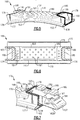
- Figure 3 is an axial view of adjacent seal assemblies 176 (indicated as 176A, 176B, 176C).
- Figure 4 is sectional view of one of the seal assemblies 176 in an installed position.
- Figures 5 and 6 illustrate perspective and plan views of the seal 169.
- Figure 7 illustrates a support or mounting block 180 of the seal assembly 176 inserted into the seal 169.
- Figure 8 illustrates a sectional view of the mounting block 180 between two adjacent seals 169 (indicated as 169A, 169B).
- 169A, 169B seals 169
- teachings herein can also be utilized for other components of the engine 20, such as one of the platforms 62, 72, 73, an upstream stage of the compressor section 24, or combustor panels or liners defining portions of a combustion chamber located in the combustor section 26.
- each seal assembly 176 includes a seal 169 and at least one support or mounting block 180.
- Each seal 169 is arranged in close proximity to an airfoil tip 164 during operation of the engine.
- An array of the seals 169 is circumferentially distributed about axis A and about an array of blades or airfoils 161 to bound a core flow path C (three seals 169A-169C shown in Figure 3 for illustrative purposes).
- Each seal 169 includes an elongated main (or seal) body 170 that extends in a circumferential direction T between opposed (or first and second) mate faces 178 and extends in an axial direction X between a leading edge portion 193 and a trailing edge portion 194.
- the main body 170 can have a generally elongated and arcuate profile, as illustrated by Figures 4 and 5 .
- the seal 169 includes a sealing portion 177 that extends circumferentially between the mate faces 178.
- the sealing portion 177 includes a front side or seal face 183 that extends circumferentially between the mate faces 178.
- the seal face 183 faces toward and bounds a gas path, such as the core flow path C, when the seal 169 is located in an installed position.
- the sealing portion 177 includes a backside or impingement face 189 that is opposite to the seal face 183.
- Each seal 169 includes at least one engagement portion 179 that extends between the mate faces 178.
- Each engagement portion 179 can extend radially outward from the sealing portion 177 when in an installed position.
- the leading and trailing edge portions 193, 194 include the radially extending walls of the main body 170 along the sealing portion 177 and/or the engagement portion 179, with the walls spanning between the mate faces 178.
- the seal 169 includes an internal cavity 184 defined by the main body 170 that extends inwardly from at least one or a pair of openings 185 along each of the respective mate faces 178 (shown in Figure 5 ).
- the internal cavity 184 extends circumferentially between the mate faces 178 and is defined in the main body 170 between the sealing portion 177 and the engagement portion 179.
- the seal 169 is made of a first material
- the mounting block 180 is made of a second, different material.
- the first material can include a ceramic or ceramic matrix composite (CMC) material.
- CMC ceramic or ceramic matrix composite
- the seal 169 can be formed from one or more layers L of a CMC layup including fibers impregnated with resin ( Figure 4 ).
- the seal 169 can be made of another material, such as a high temperature metal, alloy, or composite material.
- the mounting block 180 can be made of a second material such as a high temperature composite, metal, or alloy, such as a nickel-based superalloy, for example.
- the first and second materials can differ.
- the seal 169 is made of a first material
- the mounting block 180 is made of a second material that is the same as the first material, including any of the materials disclosed herein.
- the seal 169 is formed to have a unitary construction.
- the sealing portion 177 and each engagement portion 179 are separate and distinct components that are mechanically attached to one another with one or more fasteners.
- the mounting block 180 can be arranged to secure one or more of the seals 169 to a housing such as engine case 137, or to another portion of engine static structure 136.
- An adjacent pair of seals 169 are indicated as seals 169A, 169B in Figure 8 .
- the mounting block 180 includes at least one interface portion 181 extending outwardly from a main body or mounting portion 182.
- the mounting block 180 includes a pair of opposed interface portions 181A, 181B that extend outwardly from the mounting portion 182.
- Each interface portion 181 is dimensioned to abut the engagement portion 179 of the respective seal 169 to limit relative movement in the radial and/or circumferential directions R, T, for example.
- a cross-section of the mounting block 180 can have a generally trapezoidal geometry, as illustrated by Figures 7 and 8 .
- Surfaces of each interface portion 181 slope outwardly between a top 182A and bottom 182B of the mounting portion 182.
- the interface portions 181 can have a dovetail geometry.
- Each interface portion 181 can be inserted into or otherwise extend through a respective opening 185 to mate with ramped surfaces 186 of the internal cavity 184 (indicated as 186A, 186B in Figure 8 ) along an interface to bound movement of the seal 169 relative to the mounting block 180.
- the dovetail geometry circumferentially overlaps with walls of the engagement portions 179A, 179B when in the installed position to secure adjacent pairs of the seals 169A, 169B to the engine case 137. Ends of the interface portions 181 can be contoured to guide the interface portions 181 through one of the openings 185 and into the respective internal cavity 184 during installation.
- the dovetail geometry and contouring can reduce mechanical stress on the seal 169, including seals made of a composite material which can be strong but relative brittle.
- Each interface portion 181 can include an outwardly extending retention feature 187.
- the retention feature 187 is dimensioned to abut against surfaces of the engagement portion 179 to seat the seal 169 during assembly and limit circumferential and/or radial movement.
- the mounting block 180 can be secured to the engine case 137 using one or more fasteners 190 (one shown in Figure 8 for illustrative purposes).
- Each mounting portion 182 defines a bore 188 that receives a respective fastener 190 to mechanically attach or otherwise secure the mounting portion 182 to the housing or engine case 137 and limit relative movement of one or more seals 169.
- the fastener 190 is a bolt, and the bore 188 threadably receives a length of the bolt.
- the fastener 190 is a clip or another structure to secure the seal 169 to the engine static structure 136.
- the adjacent seals 169A, 169B are arranged in close proximity such that the respective mate faces 178A, 178B define an intersegment gap G (see also Figure 3 ) that extends a distance in the circumferential direction T.
- the mounting block 180 is situated between the mate faces 178A, 178B such that the mounting block 180 spans across the intersegment gap G.
- the mounting block 180 is arranged between the engagement portions 179A, 179B and can circumferentially space apart the seals 169A, 169B.
- the interface portions 181 abut against the adjacent seals 169A, 169B to support the seals 169A, 169B relative to the engine case 137 and limit circumferential movement of the seals 169A, 169B relative to the engine axis A.
- Each mounting block 180 secures the engagement portions 179A, 179B to the engine case 137 when in the installed position.
- the mounting block 180 is positioned at another location than along the intersegment gap G to secure the seal 169 to the engine case 137, such as a midspan of the seal 169.
- the seal assembly 176 defines a cooling arrangement 192 to deliver cooling flow F to portions of the seal 169 and/or other portions of the seal assembly 176 or components of the engine.
- the engine case 137 or another portion of the engine static structure 136 defines at least one or a plurality of cooling passages 139.
- the seal 169 is mounted to the engine case 137 such that the impingement face 189 is exposed to define one or more plenum(s) 174 that extend between the impingement face 189 and inner surfaces of the engine case 137.
- the cooling passages 139 are configured to communicate with and receive cooling flow from cooling source(s) 175.
- Each of the cooling passages 139 defines a respective passage axis PA that is oriented such that a projection of the passage axis PA intersects the main body 170 of a respective one of the seals 169.
- the cooling passages 139 are oriented such that cooling flow F is ejected into the plenum(s) 174 in a direction along the passage axis PA and toward the main body 170 of the seal 169 such that the cooling flow F impinges on surfaces of the main body 170.
- the seal 169 defines one or more apertures 191 to communicate cooling flow F to the internal cavity 184 to cool adjacent portions of the seal 169 during engine operation.
- the impingement face 189 defines the apertures 191 to the internal cavity 184.
- the apertures 191 can be distributed in one or more rows and columns in the axial and/or circumferential directions X, T, for example.
- One or more of the apertures 191 can be spaced apart from each end wall 195 of the engagement portion 179 that bounds the internal cavity 184.
- Each of the apertures 191 defines an aperture axis AA ( Figure 4 ) such that a projection of the aperture axis AA intersects a wall of the internal cavity 184.
- the apertures 191 are spaced from outlets of the cooling passages 139 and are substantially exposed and free of any obstructions when in an assembled position such that the apertures 191 communicate cooling flow F to the internal cavity 184 during engine operation. Cooling flow F communicated by the apertures 191 to the internal cavity 184 can reduce relatively sharp thermal gradients that may otherwise occur in the main body 170 due to a lack of active flow or cooling to the internal cavity 184. Reducing the thermal gradients can improve the durability of seals 169 comprising a ceramic or CMC material, for example.
- the apertures 191 can be dimensioned to meter flow from the cooling source 175 into the internal cavity 184 at a desired rate and reduce inefficiencies due to excess cooling flow F that may otherwise be communicated from the cooling source 175 to provide localized cooling.
- the apertures 191 can have a generally elliptical profile and extend in a radial direction R through a thickness of a wall of the main body 170 defining the impingement face 189.
- Other geometries of the apertures 191 can be utilized, including rectangular or complex geometries.
- a sum of the cross-sectional area of all of the apertures 191 defined in the impingement face 189 is less than 50% of a total surface area of the impingement face 189, or more narrowly between 10% and 25% of the total surface area of the impingement face 189.
- Each aperture 191 can be formed by a machining operation after forming the main body 170. Alternatively, each aperture 191 can be formed during the fabrication of the main body 170 by arranging the layers L of the CMC layup ( Figure 4 ), for example.
- the apertures 191 can be arranged relative to the cooling passages 139 to provide localized cooling to selected portions of the seal 169.
- the projection of the passage axis PA of some cooling passages 139 can intersect the impingement face 189, but the projection of the passage axis PA of other cooling passages 139 may not.
- the projection of the passage axis PA of at least some of the cooling passages 139 can be aligned with or otherwise intersect a respective one of the apertures 191.
- the projection of the passage axis PA of the cooling passage 139A intersects and is substantially collinear with the aperture axis AA of aperture 191A, thereby increasing the impingement distance between an outlet of the cooling passage 139A and localized surfaces of the internal cavity 184 that are intersected by the projection of the passage axis PA.
- the increased impingement distance can reduce the heat transfer correlation, which can reduce thermal gradients and more evenly distribute the cooling flow F in the radial direction R.
- the projection of the passage axis PA of the cooling passage 139B intersects and is transverse to aperture axis AA of aperture 191B.
- the transverse arrangement of the aperture axis AA of aperture 191B relative to the passage axis PA of cooling passage 139B can target the cooling flow F to an inlet of the aperture 191B but can cause an increase in turbulence at the inlet to provide increased cooling to portions of the main body 170 that are adjacent to the aperture 191B prior to the cooling flow F circulating into the internal cavity 184.
- Some of the apertures 191 can be offset from a projection of the passage axis PA of the cooling passage 139, as illustrated by apertures 191C in Figure 4 .
- Aligning some of the cooling passages 139 with respective apertures 191 but offsetting other cooling passages 139 with respect to each of the apertures 191 can provide a mixture of localized, impingement cooling to surfaces of the impingement face 189 and localized, impingement cooling to surfaces of the internal cavity 184.
- each aperture 191 is aligned with a respective cooling passage 139. In other examples, each aperture 191 is offset from each cooling passage 139.
- the seal 169 includes one or more apertures 191 defined in the impingement face 189 along the engagement portion 179.
- the apertures 191 are defined such that a projection of the aperture axis AA of the of apertures 191 intersect surfaces of the mounting block 180 along the interface between the mounting block 180 and the main body 170 when in the installed position.
- the projection of the passage axis PA of one or more of the cooling passages 139 can intersect a respective one of the apertures 191 that is defined along the interface between the mounting block 180 and the main body 170.
- the axes PA, AA of the respective cooling passage 139 and aperture 191 can be substantially aligned or collinear, or the axes PA, AA can be transverse to each other, such that cooling flow F is ejected from the cooling passage 139, through the respective aperture 191, and impinges on adjacent surfaces of the mounting block 180 to provide localized cooling.
- the localized cooling can reduce thermal gradients in the seal 169 and increase durability.
- a method of sealing is as follows. With reference to Figure 8 , a mounting block 180 is positioned between mate faces 178A, 178B of each adjacent pair of seals 169A, 169B. Each of the interface portions 181A, 181B is inserted or otherwise moved in a circumferential direction T through a respective one of the openings 185A, 185B and into abutment with the ramp surfaces 186A, 186B of the engagement portions 179A, 179B to bound movement of the seals 169A, 169B.
- the fastener 190 is mechanically attached or otherwise secured to the mounting block 180.
- the mounting block 180 is secured to the engine static structure 136 such that the mounting block 180 is positioned along one of the intersegment gaps G.
- pressurized cooling flow F is communicated from the cooling source 175 to the cooling passages 139.
- the cooling passages 139 eject the cooling flow F into the plenum 174 and in a direction toward the impingement face 189 of the seal 169.
- the cooling flow F can be ejected or otherwise discharged from the cooling passages 139 at a predetermined pressure and velocity such that the cooling flow F impinges on localized surfaces of the main body 170.
- the cooling passages 139 and apertures 191 can be defined such that the cooling flow F impinges on surfaces of the impingement face 189, the mounting block 180 and/or the internal cavity 184 to provide localized cooling.
- the cooling flow F circulates from the plenum 174 and into the apertures(s) 191.
- the cooling flow F circulates from the apertures(s) 191 and disperses into the internal cavity 184 to cool portions of the seal 169.
- the mounting block 180 can be dimensioned relative to surfaces of the internal cavity 184 such that cooling flow F in the internal cavity 184 can exit the openings 185 along the mate faces 178 and into the intersegment gaps G (see Figure 8 ). Communication of the cooling flow F can cool portions of the mate faces 178, thereby improving durability of the seals 169. Communicating the cooling flow F into each intersegment gap G also causes a sealing relationship to be formed, which can reduce a likelihood of ingestion of hot combustion gases from the core flow path C and into the intersegment gap G.
- the sealing portion 177 can define one or more film cooling holes 196 (shown in dashed lines in Figure 8 ) to eject cooling flow F from the internal cavity 184 into the core flow path C.
- Figure 9 illustrates a seal assembly 276 according to another example.
- a housing or engine case 237 defines a plurality of cooling passages 239.
- a projection of the passage axis PA of at least some of the cooling passages 239 intersects impingement face 289 to provide localized impingement cooling to portions of main body 270 adjacent to the impingement face 289.
- Intersection of the projection of the passage axis PA along the impingement face 289 reduces the impingement distance between an outlet of the cooling passage 239 and surfaces of the seal 269.
- the reduced impingement distance can provide targeted cooling to localized surfaces of the seal 269 and can increase the thermal gradient to more closely match the thermal profiles of adjacent portions of the seal 269.
- Each passage axis PA can be perpendicular or transverse to the impingement face 289 at the point of intersection (see, e.g., passages 239A and 239B, respectively).
- the points of intersection are spaced apart a distance from adjacent apertures 291 to allow the cooling flow F to follow along surfaces of the impingement face 289 prior to entry into the adjacent apertures 291 to cool adjacent portions of the seal 269 prior to flowing into the internal cavity 284.
- each passage axis PA intersects the impingement face 289.
- the projection of one or more of the cooling passages 239 is aligned with or otherwise intersects the apertures 291, such as cooling passages 239C (shown in dashed lines).
- each of the cooling passages 239 is aligned with or otherwise intersects a respective one of the apertures 291.
Landscapes
- Engineering & Computer Science (AREA)
- Mechanical Engineering (AREA)
- General Engineering & Computer Science (AREA)
- Chemical & Material Sciences (AREA)
- Combustion & Propulsion (AREA)
- Turbine Rotor Nozzle Sealing (AREA)
Abstract
Description
- This disclosure relates to sealing for adjacent components of a gas turbine engine.
- A gas turbine engine typically includes at least a compressor section, a combustor section and a turbine section. The compressor section pressurizes air into the combustion section where the air is mixed with fuel and ignited to generate an exhaust gas flow. The exhaust gas flow expands through the turbine section to drive the compressor section and, if the engine is designed for propulsion, a fan section.
- The turbine section may include multiple stages of rotatable blades and static vanes. An annular shroud or blade outer air seal may be provided around the blades in close radial proximity to the tips of the blades to reduce the amount of gas flow that escapes around the blades. The shroud typically includes a plurality of arc segments that are circumferentially arranged in an array. The arc segments are exposed to relatively hot gases in the gas flow path and may be configured to receive cooling airflow to cool portions of the shrouds.
- A seal assembly for a gas turbine engine according to an example of the present disclosure includes a seal that has a seal body having a sealing portion that extends from an engagement portion. The sealing portion has a seal face that extends circumferentially between first and second mate faces. The seal body defines an internal cavity that extends circumferentially between the first and second mate faces, and the engagement portion has an impingement face opposite the seal face that defines a plurality of apertures to the internal cavity. A housing is mounted to the seal such that the impingement face is exposed to define a plenum between the housing and the impingement face. The housing defines a plurality of cooling passages, and each of the plurality of cooling passages define a passage axis that is oriented such that a projection of the passage axis intersects the seal body.
- In a further embodiment of any of the foregoing embodiments, the seal is made of a first material including a ceramic material, and the seal has a unitary construction.
- In a further embodiment of any of the foregoing embodiments, the projection of the passage axis of at least some of the plurality of cooling passages intersects the impingement face.
- In a further embodiment of any of the foregoing embodiments, the projection of the passage axis of other passages of the plurality of cooling passages intersects a respective one of the plurality of apertures.
- In a further embodiment of any of the foregoing embodiments, the internal cavity extends from a first opening along the first mate face to a second opening along the second mate face.
- A further embodiment of any of the foregoing embodiments includes a mounting block that has an interface portion extending from a mounting portion. The interface portion abuts the engagement portion along an interface to limit relative movement, and the mounting portion mechanically attached to the housing.
- In a further embodiment of any of the foregoing embodiments, the projection of the passage axis of at least some of the plurality of cooling passages intersects a respective one of the plurality of apertures that is defined along the interface.
- In a further embodiment of any of the foregoing embodiments, the interface portion has a dovetail geometry that extends through the first opening to mate with ramped surfaces of the internal cavity and bound movement of the seal relative to the mounting block.
- In a further embodiment of any of the foregoing embodiments, the mounting block is a first mounting block and a second mounting block, and the interface portion of the first mounting block is received in the first opening and the interface portion of the second mounting block received in the second opening to secure the seal to the engine case.
- In a further embodiment of any of the foregoing embodiments, the projection of the passage axis of at least some of the plurality of cooling passages intersects a respective one of the plurality of apertures that is defined along an interface between the mounting block and the seal body.
- In a further embodiment of any of the foregoing embodiments, the seal is made of a first material including a ceramic material, and the mounting block is made of a second, different material.
- In a further embodiment of any of the foregoing embodiments, the seal is made of a first material including a ceramic material, and the mounting block is made of a second material that is the same as the first material.
- In a further embodiment of any of the foregoing embodiments, the seal is a blade outer air seal (BOAS).
- A gas turbine engine according to an example of the present disclosure includes an engine case that extends along an engine axis, an array of blades rotatable about the engine axis, and an array of blade outer air seals distributed about the array of blades to bound a core flow path. Each of the seals includes an elongated seal body that has a seal face that faces toward the core flow path and an opposed impingement face. The seal body defines an internal cavity that extends circumferentially between opposed mate faces, and the seal body defines a plurality of apertures to the internal cavity along the impingement face. The seal is mounted to the engine case such that the impingement face is exposed. The engine case defines a plurality of cooling passages spaced apart from the impingement face, and each of the plurality of cooling passages defines a passage axis that is oriented such that a projection of the passage axis intersects the seal body of a respective one of the seals.
- In a further embodiment of any of the foregoing embodiments, the projection of the passage axis of at least some of the plurality of cooling passages intersects the impingement face, and the projection of the passage axis of other passages of the plurality of cooling passages intersects a respective one of the plurality of apertures.
- A further embodiment of any of the foregoing embodiments includes an array of circumferentially spaced apart mounting blocks. The mate faces of adjacent seals of the array of seals are arranged to define a plurality of intersegment gaps. Each of the mounting blocks is arranged along a respective one of the plurality of intersegment gaps and engages surfaces of the respective internal cavity of the adjacent seals, and each of the mounting blocks is mechanically attached to the engine case to limit movement of the respective adjacent seals relative to the engine case.
- A method of sealing of a gas turbine engine according to an example of the present disclosure includes securing a mounting block to an engine static structure such that the mounting block is positioned along an intersegment gap between mate faces of adjacent blade outer air seals. Each of the adjacent blade outer air seals includes an elongated seal body that has a seal face that faces toward a gas path and an opposed impingement face. The seal body defines an internal cavity that extends circumferentially between opposed mate faces and defines a plurality of apertures to the internal cavity along the impingement face. The engine static structure defines a plurality of cooling passages, and each of the plurality of cooling passages defines a passage axis that is oriented such that a projection of the passage axis intersects the seal body of a respective one of the adjacent seals. The method includes ejecting cooling flow from the plurality of cooling passages such that the cooling flow impinges on surfaces of the seal body.
- In a further embodiment of any of the foregoing embodiments, the projection of the passage axis of at least some passages of the plurality of cooling passages intersects the impingement face.
- In a further embodiment of any of the foregoing embodiments, the projection of the passage axis of at least some passages of the plurality of cooling passages intersects a respective one of the plurality of apertures.
- In a further embodiment of any of the foregoing embodiments, the projection of the passage axis of one or more of the plurality of cooling passages intersects a respective one of the plurality of apertures that is defined along an interface between the mounting block and the seal body.
- The various features and advantages of this invention will become apparent to those skilled in the art from the following detailed description of an embodiment. The drawings that accompany the detailed description can be briefly described as follows.
-
-
Figure 1 shows a gas turbine engine. -
Figure 2 shows an airfoil arrangement for a turbine section. -
Figure 3 illustrates an axial view of adjacent seal assemblies. -
Figure 4 illustrates a sectional view of one of the seal assemblies including a seal along line 4-4 ofFigure 3 . -
Figure 5 illustrates an isolated perspective view of the seal ofFigure 4 . -
Figure 6 illustrates a plan view of the seal ofFigure 4 . -
Figure 7 illustrates a perspective view of a support inserted into the seal ofFigure 4 . -
Figure 8 illustrates a sectional view of the support ofFigure 7 between two adjacent seals. -
Figure 9 illustrates a sectional view of a seal assembly according to another example. -
Figure 1 schematically illustrates agas turbine engine 20. Thegas turbine engine 20 is disclosed herein as a two-spool turbofan that generally incorporates afan section 22, acompressor section 24, acombustor section 26 and aturbine section 28. Thefan section 22 drives air along a bypass flow path B in a bypass duct defined within anacelle 15, while thecompressor section 24 drives air along a core flow path C for compression and communication into thecombustor section 26 then expansion through theturbine section 28. Although depicted as a two-spool turbofan gas turbine engine in the disclosed non-limiting embodiment, it should be understood that the concepts described herein are not limited to use with two-spool turbofans as the teachings may be applied to other types of turbine engines including three-spool architectures. - The
exemplary engine 20 generally includes alow speed spool 30 and ahigh speed spool 32 mounted for rotation about an engine central longitudinal axis A relative to an enginestatic structure 36 viaseveral bearing systems 38. It should be understood thatvarious bearing systems 38 at various locations may alternatively or additionally be provided, and the location ofbearing systems 38 may be varied as appropriate to the application. - The
low speed spool 30 generally includes aninner shaft 40 that interconnects afan 42, a first (or low)pressure compressor 44 and a first (or low)pressure turbine 46. Theinner shaft 40 is connected to thefan 42 through a speed change mechanism, which in exemplarygas turbine engine 20 is illustrated as a gearedarchitecture 48 to drive thefan 42 at a lower speed than thelow speed spool 30. Thehigh speed spool 32 includes anouter shaft 50 that interconnects a second (or high)pressure compressor 52 and a second (or high)pressure turbine 54. Acombustor 56 is arranged inexemplary gas turbine 20 between thehigh pressure compressor 52 and thehigh pressure turbine 54. Amid-turbine frame 57 of the enginestatic structure 36 is arranged generally between thehigh pressure turbine 54 and thelow pressure turbine 46. Themid-turbine frame 57 furthersupports bearing systems 38 in theturbine section 28. Theinner shaft 40 and theouter shaft 50 are concentric and rotate via bearingsystems 38 about the engine central longitudinal axis A which is collinear with their longitudinal axes. - The core airflow is compressed by the
low pressure compressor 44 then thehigh pressure compressor 52, mixed and burned with fuel in thecombustor 56, then expanded over thehigh pressure turbine 54 andlow pressure turbine 46. Themid-turbine frame 57 includesairfoils 59 which are in the core airflow path C. Theturbines low speed spool 30 andhigh speed spool 32 in response to the expansion. It will be appreciated that each of the positions of thefan section 22,compressor section 24,combustor section 26,turbine section 28, and fandrive gear system 48 may be varied. For example,gear system 48 may be located aft ofcombustor section 26 or even aft ofturbine section 28, andfan section 22 may be positioned forward or aft of the location ofgear system 48. - The
engine 20 in one example is a high-bypass geared aircraft engine. In a further example, theengine 20 bypass ratio is greater than about six (6), with an example embodiment being greater than about ten (10), the gearedarchitecture 48 is an epicyclic gear train, such as a planetary gear system or other gear system, with a gear reduction ratio of greater than about 2.3 and thelow pressure turbine 46 has a pressure ratio that is greater than about five. In one disclosed embodiment, theengine 20 bypass ratio is greater than about ten (10:1), the fan diameter is significantly larger than that of thelow pressure compressor 44, and thelow pressure turbine 46 has a pressure ratio that is greater than about five 5:1.Low pressure turbine 46 pressure ratio is pressure measured prior to inlet oflow pressure turbine 46 as related to the pressure at the outlet of thelow pressure turbine 46 prior to an exhaust nozzle. The gearedarchitecture 48 may be an epicycle gear train, such as a planetary gear system or other gear system, with a gear reduction ratio of greater than about 2.3:1. It should be understood, however, that the above parameters are only exemplary of one embodiment of a geared architecture engine and that the present invention is applicable to other gas turbine engines including direct drive turbofans. - A significant amount of thrust is provided by the bypass flow B due to the high bypass ratio. The
fan section 22 of theengine 20 is designed for a particular flight condition -- typically cruise at about 0.8 Mach and about 35,000 feet (10.7 km). The flight condition of 0.8 Mach and 35,000 ft (10.7 km), with the engine at its best fuel consumption - also known as "bucket cruise Thrust Specific Fuel Consumption ('TSFC')" - is the industry standard parameter of lbm of fuel being burned divided by lbf of thrust the engine produces at that minimum point. "Low fan pressure ratio" is the pressure ratio across the fan blade alone, without a Fan Exit Guide Vane ("FEGV") system. The low fan pressure ratio as disclosed herein according to one non-limiting embodiment is less than about 1.45. "Low corrected fan tip speed" is the actual fan tip speed in ft/sec divided by an industry standard temperature correction of [(Tram °R) / (518.7 °R)]^0.5 (where °R = K x 9/5). The "Low corrected fan tip speed" as disclosed herein according to one non-limiting embodiment is less than about 1150 ft / second (351 m/s). -
Figure 2 shows selected portions of theturbine section 28 including arotor 60 carrying one or more blades orairfoils 61 that are rotatable about the engine axis A. In this disclosure, like reference numerals designate like elements where appropriate and reference numerals with the addition of one-hundred or multiples thereof designate modified elements that are understood to incorporate the same features and benefits of the corresponding original elements. Eachairfoil 61 includes aplatform 62 and anairfoil section 65 extending in a radial direction R from theplatform 62 to atip 64. Theairfoil section 65 generally extends in a chordwise or axial direction X between aleading edge 66 and a trailingedge 68. Aroot section 67 of theairfoil 61 is mounted to, or integrally formed with, therotor 60. A blade outer air seal (BOAS) 69 is spaced radially outward from thetip 64 of theairfoil section 65. TheBOAS 69 can include a plurality of seal arc segments (one shown inFigure 3 at 169) that are circumferentially arranged in an annulus around the engine axis A. An array of theBOAS 69 are distributed about an array of theairfoils 61 to bound the core flow path C. - A
vane 70 is positioned along the engine axis A and adjacent to theairfoil 61. Thevane 70 includes anairfoil section 71 extending between aninner platform 72 and anouter platform 73 to define a portion of the core flow path C. Theturbine section 28 includes an array ofairfoils 61,vanes 70, andBOAS 69 arranged circumferentially about the engine axis A. - One or more cooling sources 75 (one shown) are configured to provide cooling air to one or more cooling cavities or
plenums 74 defined by an engine static structure such as theengine case 37 or another portion of the engine static structure 36 (Figure 1 ). Theengine case 37 extends along the engine axis A. In the illustrated example ofFigure 2 , theplenums 74 are defined between anengine case 37 and theouter platform 73 and/orBOAS 69. Theengine case 37 provides a portion of the engine static structure 36 (Figure 1 ) and extends along the engine axis A. Theplenums 74 are configured to receive pressurized cooling flow from the cooling source(s) 75 to cool portions of theairfoil 61,BOAS 69 and/orvane 70.Cooling sources 75 can include bleed air from an upstream stage of the compressor section 24 (Figure 1 ), bypass air, or a secondary cooling system aboard the aircraft, for example. Each of theplenums 74 can extend in a circumferential or thickness direction T betweenadjacent airfoils 61,BOAS 69 and/orvanes 70. Thetips 64 of each of theairfoil sections 65 andadjacent BOAS 69 are in close radial proximity to reduce the amount of gas flow that escapes around thetips 64 through a corresponding clearance gap. -
Figures 3-8 illustrate anexemplary seal assembly 176 for sealing portions a gas turbine engine. Theseal assembly 176 can be utilized for theseal assembly 76 ofFigure 2 or incorporated into a portion of theengine 20 ofFigure 1 , for example. In the illustrated example ofFigures 3-8 , theseal 169 is a blade outer air seal (BOAS).Figure 3 is an axial view of adjacent seal assemblies 176 (indicated as 176A, 176B, 176C).Figure 4 is sectional view of one of theseal assemblies 176 in an installed position.Figures 5 and 6 illustrate perspective and plan views of theseal 169.Figure 7 illustrates a support or mountingblock 180 of theseal assembly 176 inserted into theseal 169.Figure 8 illustrates a sectional view of the mountingblock 180 between two adjacent seals 169 (indicated as 169A, 169B). Although the components discussed herein primarily refer to a BOAS in theturbine section 28, the teachings herein can also be utilized for other components of theengine 20, such as one of theplatforms compressor section 24, or combustor panels or liners defining portions of a combustion chamber located in thecombustor section 26. - Referring to
Figures 3 and 4 , eachseal assembly 176 includes aseal 169 and at least one support or mountingblock 180. Eachseal 169 is arranged in close proximity to anairfoil tip 164 during operation of the engine. An array of theseals 169 is circumferentially distributed about axis A and about an array of blades orairfoils 161 to bound a core flow path C (threeseals 169A-169C shown inFigure 3 for illustrative purposes). - Each
seal 169 includes an elongated main (or seal)body 170 that extends in a circumferential direction T between opposed (or first and second) mate faces 178 and extends in an axial direction X between aleading edge portion 193 and a trailingedge portion 194. Themain body 170 can have a generally elongated and arcuate profile, as illustrated byFigures 4 and5 . Theseal 169 includes a sealingportion 177 that extends circumferentially between the mate faces 178. The sealingportion 177 includes a front side or sealface 183 that extends circumferentially between the mate faces 178. Theseal face 183 faces toward and bounds a gas path, such as the core flow path C, when theseal 169 is located in an installed position. The sealingportion 177 includes a backside orimpingement face 189 that is opposite to theseal face 183. - Each
seal 169 includes at least oneengagement portion 179 that extends between the mate faces 178. Eachengagement portion 179 can extend radially outward from the sealingportion 177 when in an installed position. The leading and trailingedge portions main body 170 along the sealingportion 177 and/or theengagement portion 179, with the walls spanning between the mate faces 178. - The
seal 169 includes aninternal cavity 184 defined by themain body 170 that extends inwardly from at least one or a pair ofopenings 185 along each of the respective mate faces 178 (shown inFigure 5 ). In the illustrated example ofFigures 3-8 , theinternal cavity 184 extends circumferentially between the mate faces 178 and is defined in themain body 170 between the sealingportion 177 and theengagement portion 179. - Various materials can be utilized to manufacture the
seal 169 and mountingblock 180. In some examples, theseal 169 is made of a first material, and the mountingblock 180 is made of a second, different material. For example, the first material can include a ceramic or ceramic matrix composite (CMC) material. Theseal 169 can be formed from one or more layers L of a CMC layup including fibers impregnated with resin (Figure 4 ). Theseal 169 can be made of another material, such as a high temperature metal, alloy, or composite material. The mountingblock 180 can be made of a second material such as a high temperature composite, metal, or alloy, such as a nickel-based superalloy, for example. The first and second materials can differ. In other examples, theseal 169 is made of a first material, and the mountingblock 180 is made of a second material that is the same as the first material, including any of the materials disclosed herein. Theseal 169 is formed to have a unitary construction. In alternative examples, the sealingportion 177 and eachengagement portion 179 are separate and distinct components that are mechanically attached to one another with one or more fasteners. - Referring to
Figures 7 and8 , the mountingblock 180 can be arranged to secure one or more of theseals 169 to a housing such as engine case 137, or to another portion of engine static structure 136. An adjacent pair ofseals 169 are indicated asseals Figure 8 . The mountingblock 180 includes at least oneinterface portion 181 extending outwardly from a main body or mountingportion 182. In the illustrated example ofFigures 7 and8 , the mountingblock 180 includes a pair ofopposed interface portions portion 182. Eachinterface portion 181 is dimensioned to abut theengagement portion 179 of therespective seal 169 to limit relative movement in the radial and/or circumferential directions R, T, for example. - A cross-section of the mounting
block 180 can have a generally trapezoidal geometry, as illustrated byFigures 7 and8 . Surfaces of eachinterface portion 181 slope outwardly between a top 182A and bottom 182B of the mountingportion 182. Theinterface portions 181 can have a dovetail geometry. Eachinterface portion 181 can be inserted into or otherwise extend through arespective opening 185 to mate with rampedsurfaces 186 of the internal cavity 184 (indicated as 186A, 186B inFigure 8 ) along an interface to bound movement of theseal 169 relative to themounting block 180. The dovetail geometry circumferentially overlaps with walls of theengagement portions seals interface portions 181 can be contoured to guide theinterface portions 181 through one of theopenings 185 and into the respectiveinternal cavity 184 during installation. The dovetail geometry and contouring can reduce mechanical stress on theseal 169, including seals made of a composite material which can be strong but relative brittle. - Each
interface portion 181 can include an outwardly extendingretention feature 187. Theretention feature 187 is dimensioned to abut against surfaces of theengagement portion 179 to seat theseal 169 during assembly and limit circumferential and/or radial movement. - The mounting
block 180 can be secured to the engine case 137 using one or more fasteners 190 (one shown inFigure 8 for illustrative purposes). Each mountingportion 182 defines abore 188 that receives arespective fastener 190 to mechanically attach or otherwise secure the mountingportion 182 to the housing or engine case 137 and limit relative movement of one ormore seals 169. In the illustrated example ofFigure 8 , thefastener 190 is a bolt, and thebore 188 threadably receives a length of the bolt. In alternative examples, thefastener 190 is a clip or another structure to secure theseal 169 to the engine static structure 136. - In the illustrated example of
Figure 8 , theadjacent seals Figure 3 ) that extends a distance in the circumferential direction T. The mountingblock 180 is situated between the mate faces 178A, 178B such that the mountingblock 180 spans across the intersegment gap G. The mountingblock 180 is arranged between theengagement portions seals interface portions 181 abut against theadjacent seals seals seals block 180 secures theengagement portions block 180 is positioned at another location than along the intersegment gap G to secure theseal 169 to the engine case 137, such as a midspan of theseal 169. - Referring back to
Figures 3-4 , with continued reference toFigures 5-8 , theseal assembly 176 defines acooling arrangement 192 to deliver cooling flow F to portions of theseal 169 and/or other portions of theseal assembly 176 or components of the engine. The engine case 137 or another portion of the engine static structure 136 defines at least one or a plurality of coolingpassages 139. Theseal 169 is mounted to the engine case 137 such that theimpingement face 189 is exposed to define one or more plenum(s) 174 that extend between theimpingement face 189 and inner surfaces of the engine case 137. Thecooling passages 139 are configured to communicate with and receive cooling flow from cooling source(s) 175. - Each of the
cooling passages 139 defines a respective passage axis PA that is oriented such that a projection of the passage axis PA intersects themain body 170 of a respective one of theseals 169. Thecooling passages 139 are oriented such that cooling flow F is ejected into the plenum(s) 174 in a direction along the passage axis PA and toward themain body 170 of theseal 169 such that the cooling flow F impinges on surfaces of themain body 170. - The
seal 169 defines one ormore apertures 191 to communicate cooling flow F to theinternal cavity 184 to cool adjacent portions of theseal 169 during engine operation. In the illustrated example ofFigures 3-8 , theimpingement face 189 defines theapertures 191 to theinternal cavity 184. Theapertures 191 can be distributed in one or more rows and columns in the axial and/or circumferential directions X, T, for example. One or more of theapertures 191 can be spaced apart from eachend wall 195 of theengagement portion 179 that bounds theinternal cavity 184. Each of theapertures 191 defines an aperture axis AA (Figure 4 ) such that a projection of the aperture axis AA intersects a wall of theinternal cavity 184. Theapertures 191 are spaced from outlets of thecooling passages 139 and are substantially exposed and free of any obstructions when in an assembled position such that theapertures 191 communicate cooling flow F to theinternal cavity 184 during engine operation. Cooling flow F communicated by theapertures 191 to theinternal cavity 184 can reduce relatively sharp thermal gradients that may otherwise occur in themain body 170 due to a lack of active flow or cooling to theinternal cavity 184. Reducing the thermal gradients can improve the durability ofseals 169 comprising a ceramic or CMC material, for example. - The
apertures 191 can be dimensioned to meter flow from thecooling source 175 into theinternal cavity 184 at a desired rate and reduce inefficiencies due to excess cooling flow F that may otherwise be communicated from thecooling source 175 to provide localized cooling. Theapertures 191 can have a generally elliptical profile and extend in a radial direction R through a thickness of a wall of themain body 170 defining theimpingement face 189. Other geometries of theapertures 191 can be utilized, including rectangular or complex geometries. In examples, a sum of the cross-sectional area of all of theapertures 191 defined in theimpingement face 189 is less than 50% of a total surface area of theimpingement face 189, or more narrowly between 10% and 25% of the total surface area of theimpingement face 189. - Each
aperture 191 can be formed by a machining operation after forming themain body 170. Alternatively, eachaperture 191 can be formed during the fabrication of themain body 170 by arranging the layers L of the CMC layup (Figure 4 ), for example. - The
apertures 191 can be arranged relative to thecooling passages 139 to provide localized cooling to selected portions of theseal 169. The projection of the passage axis PA of somecooling passages 139 can intersect theimpingement face 189, but the projection of the passage axis PA ofother cooling passages 139 may not. In the illustrative example ofFigures 3 and 4 , the projection of the passage axis PA of at least some of thecooling passages 139 can be aligned with or otherwise intersect a respective one of theapertures 191. In the illustrated example ofFigure 4 , the projection of the passage axis PA of the cooling passage 139A intersects and is substantially collinear with the aperture axis AA of aperture 191A, thereby increasing the impingement distance between an outlet of the cooling passage 139A and localized surfaces of theinternal cavity 184 that are intersected by the projection of the passage axis PA. The increased impingement distance can reduce the heat transfer correlation, which can reduce thermal gradients and more evenly distribute the cooling flow F in the radial direction R. - The projection of the passage axis PA of the cooling passage 139B intersects and is transverse to aperture axis AA of aperture 191B. The transverse arrangement of the aperture axis AA of aperture 191B relative to the passage axis PA of cooling passage 139B can target the cooling flow F to an inlet of the aperture 191B but can cause an increase in turbulence at the inlet to provide increased cooling to portions of the
main body 170 that are adjacent to the aperture 191B prior to the cooling flow F circulating into theinternal cavity 184. Some of theapertures 191 can be offset from a projection of the passage axis PA of thecooling passage 139, as illustrated byapertures 191C inFigure 4 . Aligning some of thecooling passages 139 withrespective apertures 191 but offsettingother cooling passages 139 with respect to each of theapertures 191 can provide a mixture of localized, impingement cooling to surfaces of theimpingement face 189 and localized, impingement cooling to surfaces of theinternal cavity 184. In examples, eachaperture 191 is aligned with arespective cooling passage 139. In other examples, eachaperture 191 is offset from eachcooling passage 139. - The mounting blocks 180 can be exposed to relatively hot gases in the core flow path C adjacent to the intersegment gaps G. In the illustrated example of
Figures 3 and8 , theseal 169 includes one ormore apertures 191 defined in theimpingement face 189 along theengagement portion 179. Theapertures 191 are defined such that a projection of the aperture axis AA of the ofapertures 191 intersect surfaces of the mountingblock 180 along the interface between the mountingblock 180 and themain body 170 when in the installed position. The projection of the passage axis PA of one or more of thecooling passages 139 can intersect a respective one of theapertures 191 that is defined along the interface between the mountingblock 180 and themain body 170. The axes PA, AA of therespective cooling passage 139 andaperture 191 can be substantially aligned or collinear, or the axes PA, AA can be transverse to each other, such that cooling flow F is ejected from thecooling passage 139, through therespective aperture 191, and impinges on adjacent surfaces of the mountingblock 180 to provide localized cooling. The localized cooling can reduce thermal gradients in theseal 169 and increase durability. - A method of sealing is as follows. With reference to
Figure 8 , a mountingblock 180 is positioned between mate faces 178A, 178B of each adjacent pair ofseals interface portions engagement portions seals fastener 190 is mechanically attached or otherwise secured to themounting block 180. The mountingblock 180 is secured to the engine static structure 136 such that the mountingblock 180 is positioned along one of the intersegment gaps G. - Referring to
Figures 3-4 , with continued reference toFigure 8 , during operation of the engine, pressurized cooling flow F is communicated from thecooling source 175 to thecooling passages 139. Thecooling passages 139 eject the cooling flow F into theplenum 174 and in a direction toward theimpingement face 189 of theseal 169. The cooling flow F can be ejected or otherwise discharged from thecooling passages 139 at a predetermined pressure and velocity such that the cooling flow F impinges on localized surfaces of themain body 170. Thecooling passages 139 andapertures 191 can be defined such that the cooling flow F impinges on surfaces of theimpingement face 189, the mountingblock 180 and/or theinternal cavity 184 to provide localized cooling. The cooling flow F circulates from theplenum 174 and into the apertures(s) 191. The cooling flow F circulates from the apertures(s) 191 and disperses into theinternal cavity 184 to cool portions of theseal 169. - The mounting
block 180 can be dimensioned relative to surfaces of theinternal cavity 184 such that cooling flow F in theinternal cavity 184 can exit theopenings 185 along the mate faces 178 and into the intersegment gaps G (seeFigure 8 ). Communication of the cooling flow F can cool portions of the mate faces 178, thereby improving durability of theseals 169. Communicating the cooling flow F into each intersegment gap G also causes a sealing relationship to be formed, which can reduce a likelihood of ingestion of hot combustion gases from the core flow path C and into the intersegment gap G. In examples, the sealingportion 177 can define one or more film cooling holes 196 (shown in dashed lines inFigure 8 ) to eject cooling flow F from theinternal cavity 184 into the core flow path C. -
Figure 9 illustrates aseal assembly 276 according to another example. A housing or engine case 237 defines a plurality of cooling passages 239. A projection of the passage axis PA of at least some of the cooling passages 239 intersectsimpingement face 289 to provide localized impingement cooling to portions ofmain body 270 adjacent to theimpingement face 289. - Intersection of the projection of the passage axis PA along the
impingement face 289 reduces the impingement distance between an outlet of the cooling passage 239 and surfaces of theseal 269. The reduced impingement distance can provide targeted cooling to localized surfaces of theseal 269 and can increase the thermal gradient to more closely match the thermal profiles of adjacent portions of theseal 269. Each passage axis PA can be perpendicular or transverse to theimpingement face 289 at the point of intersection (see, e.g.,passages 239A and 239B, respectively). The points of intersection are spaced apart a distance fromadjacent apertures 291 to allow the cooling flow F to follow along surfaces of theimpingement face 289 prior to entry into theadjacent apertures 291 to cool adjacent portions of theseal 269 prior to flowing into theinternal cavity 284. - In the illustrated example of
Figure 9 , the projection of each passage axis PA intersects theimpingement face 289. In some examples, the projection of one or more of the cooling passages 239 is aligned with or otherwise intersects theapertures 291, such ascooling passages 239C (shown in dashed lines). In other examples, each of the cooling passages 239 is aligned with or otherwise intersects a respective one of theapertures 291. - It should be understood that relative positional terms such as "forward," "aft," "upper," "lower," "above," "below," and the like are with reference to the normal operational attitude of the vehicle and should not be considered otherwise limiting.
- Although the different examples have the specific components shown in the illustrations, embodiments of this disclosure are not limited to those particular combinations. It is possible to use some of the components or features from one of the examples in combination with features or components from another one of the examples.
- Although particular step sequences are shown, described, and claimed, it should be understood that steps may be performed in any order, separated or combined unless otherwise indicated and will still benefit from the present disclosure.
- The foregoing description is exemplary rather than defined by the limitations within. Various non-limiting embodiments are disclosed herein, however, one of ordinary skill in the art would recognize that various modifications and variations in light of the above teachings will fall within the scope of the appended claims. It is therefore to be understood that within the scope of the appended claims, the disclosure may be practiced other than as specifically described. For that reason the appended claims should be studied to determine true scope and content.
Claims (15)
- A seal assembly (176; 276) for a gas turbine engine (20) comprising:a seal (169; 269) including a seal body (170; 270) having a sealing portion (177) that extends from an engagement portion (179; 279), the sealing portion (177) including a seal face (183) that extends circumferentially between first and second mate faces (178; 278), the seal body (170; 270) defining an internal cavity (184; 284) that extends circumferentially between the first and second mate faces (178; 278), and the engagement portion (179;279) including an impingement face (189; 289) opposite the seal face (178; 278) that defines a plurality of apertures (191; 291) to the internal cavity (184; 284); anda housing (137; 237) mounted to the seal (169; 269) such that the impingement face (189; 289) is exposed to define a plenum (174; 274) between the housing (137; 237) and the impingement face (189; 289), the housing (137; 237) defining a plurality of cooling passages (139; 239), and each of the plurality of cooling passages (139; 239) defining a passage axis (PA) that is oriented such that a projection of the passage axis (PA) intersects the seal body (170; 270).
- The seal assembly as recited in claim 1, wherein the seal (169; 269) is made of a first material including a ceramic material, and the seal (169; 269) has a unitary construction.
- The seal assembly as recited in claim 1 or 2, wherein the internal cavity (184; 284) extends from a first opening (185) along the first mate face (178; 278) to a second opening (185) along the second mate face (178; 278).
- The seal assembly as recited in claim 3, further comprising a mounting block (180) including an interface portion (181) extending from a mounting portion (182), the interface portion (181) abutting the engagement portion (179; 279) along an interface between the mounting block (180) and the seal body (170; 270) to limit relative movement, and the mounting portion (182) mechanically attached to the housing (137; 237).
- The seal assembly as recited in claim 4, wherein the projection of the passage axis (PA) of at least some of the plurality of cooling passages (139; 239) intersects a respective one of the plurality of apertures (191; 291) that is defined along the interface.
- The seal assembly as recited in claim 4 or 5, wherein the interface portion (181) has a dovetail geometry that extends through the first opening (185) to mate with ramped surfaces (186) of the internal cavity (184; 284) and bound movement of the seal (169; 269) relative to the mounting block (180).
- The seal assembly as recited in claim 4, 5 or 6, wherein the mounting block (180) is a first mounting block and a second mounting block, and the interface portion (181) of the first mounting block is received in the first opening (185) and the interface portion (181) of the second mounting block is received in the second opening (185) to secure the seal (169; 269) to the housing (137; 237).
- The seal assembly as recited in any of claims 4 to 7, wherein the seal (169; 269) is made of a first material including a ceramic material, and the mounting block (180) is made of a second, different material.
- The seal assembly as recited in any of claims 4 to 7, wherein the seal (169; 269) is made of a first material including a ceramic material, and the mounting block (180) is made of a second material that is the same as the first material.
- The seal assembly as recited in any preceding claim, wherein the seal (169; 269) is a blade outer air seal (BOAS).
- A gas turbine engine (20) comprising:the seal assembly of claim 10, wherein the housing (136; 236) is an engine case (136; 236) extending along an engine axis (A);an array of blades (61; 161; 261) rotatable about the engine axis (A); andan array of the blade outer air seals (169; 269) distributed about the array of blades (61; 161; 261) to bound a core flow path (C), wherein the seal face (183) faces toward the core flow path (C).
- The gas turbine engine as recited in claim 11, further comprising an array of circumferentially spaced apart mounting blocks (180), wherein the mate faces (178; 278) of adjacent seals of the array of seals (169; 269) are arranged to define a plurality of intersegment gaps (G), each of the mounting blocks (180) is arranged along a respective one of the plurality of intersegment gaps (G) and engages surfaces of the respective internal cavity (184; 284) of the adjacent seals (169; 269), and each of the mounting blocks (180) is mechanically attached to the engine case (136; 236) to limit movement of the respective adjacent seals (169; 269) relative to the engine case (136; 236).
- A method of sealing of a gas turbine engine (20), comprising:securing a mounting block (180) to an engine static structure (137; 237) such that the mounting block (180) is positioned along an intersegment gap (G) between mate faces (178; 278) of adjacent blade outer air seals (169; 269);wherein each of the adjacent blade outer air seals (169; 269) comprises:an elongated seal body (170; 270) including a seal face (183) that faces toward a gas path (C) and an opposed impingement face (189; 289); andwherein the seal body (170; 270) defines an internal cavity (184; 284) that extends circumferentially between opposed mate faces (178; 278) and defines a plurality of apertures (191; 291) to the internal cavity (184; 284) along the impingement face (189; 289);wherein the engine static structure (137; 237) defines a plurality of cooling passages (139; 239), and each of the plurality of cooling passages (139; 239) defines a passage axis (PA) that is oriented such that a projection of the passage axis (PA) intersects the seal body (170; 270) of a respective one of the adjacent seals (169; 269); andejecting cooling flow (F) from the plurality of cooling passages (139; 239) such that the cooling flow impinges on surfaces of the seal body (170; 270).
- The method as recited in claim 13, wherein the projection of the passage axis (PA) of one or more of the plurality of cooling passages (139; 239) intersects a respective one of the plurality of apertures (191; 291) that is defined along an interface between the mounting block (180) and the seal body (170; 270).
- The seal assembly, gas turbine engine, or method as recited in any preceding claim, wherein the projection of the passage axis (PA) of at least some of the plurality of cooling passages (139; 239) intersects the impingement face (189; 289), and the projection of the passage axis (PA) of other passages of the plurality of cooling passages (139; 239) intersects a respective one of the plurality of apertures (191; 291).
Applications Claiming Priority (1)
| Application Number | Priority Date | Filing Date | Title |
|---|---|---|---|
| US15/955,585 US10689997B2 (en) | 2018-04-17 | 2018-04-17 | Seal assembly for gas turbine engine |
Publications (2)
| Publication Number | Publication Date |
|---|---|
| EP3557003A1 true EP3557003A1 (en) | 2019-10-23 |
| EP3557003B1 EP3557003B1 (en) | 2021-12-22 |
Family
ID=66217780
Family Applications (1)
| Application Number | Title | Priority Date | Filing Date |
|---|---|---|---|
| EP19169528.7A Active EP3557003B1 (en) | 2018-04-17 | 2019-04-16 | Seal assembly for gas turbine engine |
Country Status (2)
| Country | Link |
|---|---|
| US (1) | US10689997B2 (en) |
| EP (1) | EP3557003B1 (en) |
Cited By (1)
| Publication number | Priority date | Publication date | Assignee | Title |
|---|---|---|---|---|
| EP3650657A1 (en) * | 2018-11-08 | 2020-05-13 | United Technologies Corporation | Seal assembly with impingement seal plate |
Families Citing this family (1)
| Publication number | Priority date | Publication date | Assignee | Title |
|---|---|---|---|---|
| US10934878B2 (en) * | 2018-12-05 | 2021-03-02 | Raytheon Technologies Corporation | CMC loop boas |
Citations (5)
| Publication number | Priority date | Publication date | Assignee | Title |
|---|---|---|---|---|
| US20080206042A1 (en) * | 2006-11-30 | 2008-08-28 | Ching-Pang Lee | Methods and system for recuperated circumferential cooling of integral turbine nozzle and shroud assemblies |
| US20110182724A1 (en) * | 2010-01-26 | 2011-07-28 | Mitsubishi Heavy Industries, Ltd. | Cooling system of ring segment and gas turbine |
| US8061979B1 (en) * | 2007-10-19 | 2011-11-22 | Florida Turbine Technologies, Inc. | Turbine BOAS with edge cooling |
| US20160290144A1 (en) * | 2015-04-01 | 2016-10-06 | Herakles | Turbine ring assembly with inter-sector connections |
| EP3214274A1 (en) * | 2016-02-26 | 2017-09-06 | General Electric Company | Encapsulated cooling for turbine shrouds |
Family Cites Families (19)
| Publication number | Priority date | Publication date | Assignee | Title |
|---|---|---|---|---|
| GB2125111B (en) * | 1982-03-23 | 1985-06-05 | Rolls Royce | Shroud assembly for a gas turbine engine |
| US5486090A (en) * | 1994-03-30 | 1996-01-23 | United Technologies Corporation | Turbine shroud segment with serpentine cooling channels |
| US5738490A (en) * | 1996-05-20 | 1998-04-14 | Pratt & Whitney Canada, Inc. | Gas turbine engine shroud seals |
| JP2004036443A (en) * | 2002-07-02 | 2004-02-05 | Ishikawajima Harima Heavy Ind Co Ltd | Gas turbine shroud structure |
| US6758653B2 (en) * | 2002-09-09 | 2004-07-06 | Siemens Westinghouse Power Corporation | Ceramic matrix composite component for a gas turbine engine |
| US6942203B2 (en) | 2003-11-04 | 2005-09-13 | General Electric Company | Spring mass damper system for turbine shrouds |
| US7063503B2 (en) * | 2004-04-15 | 2006-06-20 | Pratt & Whitney Canada Corp. | Turbine shroud cooling system |
| US7306424B2 (en) * | 2004-12-29 | 2007-12-11 | United Technologies Corporation | Blade outer seal with micro axial flow cooling system |
| GB0703827D0 (en) * | 2007-02-28 | 2007-04-11 | Rolls Royce Plc | Rotor seal segment |
| US9145779B2 (en) * | 2009-03-12 | 2015-09-29 | United Technologies Corporation | Cooling arrangement for a turbine engine component |
| US8834105B2 (en) | 2010-12-30 | 2014-09-16 | General Electric Company | Structural low-ductility turbine shroud apparatus |
| US20120292856A1 (en) * | 2011-05-16 | 2012-11-22 | United Technologies Corporation | Blade outer seal for a gas turbine engine having non-parallel segment confronting faces |
| US8596963B1 (en) * | 2011-07-07 | 2013-12-03 | Florida Turbine Technologies, Inc. | BOAS for a turbine |
| US20130340966A1 (en) * | 2012-06-21 | 2013-12-26 | United Technologies Corporation | Blade outer air seal hybrid casting core |
| GB201213039D0 (en) | 2012-07-23 | 2012-09-05 | Rolls Royce Plc | Fastener |
| CA2912428C (en) | 2013-05-17 | 2018-03-13 | General Electric Company | Cmc shroud support system of a gas turbine |
| JP6180007B2 (en) | 2014-01-17 | 2017-08-16 | ゼネラル・エレクトリック・カンパニイ | CMC hanger sleeve for CMC shroud |
| US10443423B2 (en) * | 2014-09-22 | 2019-10-15 | United Technologies Corporation | Gas turbine engine blade outer air seal assembly |
| US10184352B2 (en) | 2015-06-29 | 2019-01-22 | Rolls-Royce North American Technologies Inc. | Turbine shroud segment with integrated cooling air distribution system |
-
2018
- 2018-04-17 US US15/955,585 patent/US10689997B2/en active Active
-
2019
- 2019-04-16 EP EP19169528.7A patent/EP3557003B1/en active Active
Patent Citations (5)
| Publication number | Priority date | Publication date | Assignee | Title |
|---|---|---|---|---|
| US20080206042A1 (en) * | 2006-11-30 | 2008-08-28 | Ching-Pang Lee | Methods and system for recuperated circumferential cooling of integral turbine nozzle and shroud assemblies |
| US8061979B1 (en) * | 2007-10-19 | 2011-11-22 | Florida Turbine Technologies, Inc. | Turbine BOAS with edge cooling |
| US20110182724A1 (en) * | 2010-01-26 | 2011-07-28 | Mitsubishi Heavy Industries, Ltd. | Cooling system of ring segment and gas turbine |
| US20160290144A1 (en) * | 2015-04-01 | 2016-10-06 | Herakles | Turbine ring assembly with inter-sector connections |
| EP3214274A1 (en) * | 2016-02-26 | 2017-09-06 | General Electric Company | Encapsulated cooling for turbine shrouds |
Cited By (2)
| Publication number | Priority date | Publication date | Assignee | Title |
|---|---|---|---|---|
| EP3650657A1 (en) * | 2018-11-08 | 2020-05-13 | United Technologies Corporation | Seal assembly with impingement seal plate |
| US10968761B2 (en) | 2018-11-08 | 2021-04-06 | Raytheon Technologies Corporation | Seal assembly with impingement seal plate |
Also Published As
| Publication number | Publication date |
|---|---|
| US20190316480A1 (en) | 2019-10-17 |
| EP3557003B1 (en) | 2021-12-22 |
| US10689997B2 (en) | 2020-06-23 |
Similar Documents
| Publication | Publication Date | Title |
|---|---|---|
| US11174747B2 (en) | Seal assembly with distributed cooling arrangement | |
| US11035243B2 (en) | Seal assembly for gas turbine engines | |
| EP3543484B1 (en) | Seal assembly for gas turbine engine and method of sealing | |
| EP3081753B1 (en) | Blade tip cooling arrangement | |
| EP3557004B1 (en) | Seal assembly for gas turbine engine | |
| US11781439B2 (en) | Seal arrangement for turbine engine component | |
| EP3620616B1 (en) | Turbine section with boas cooling air flow guide | |
| EP3620615B1 (en) | Cmc boas assembly with axial retaining clip | |
| EP3569823B1 (en) | Seal assembly with baffle for gas turbine engine | |
| EP3557003B1 (en) | Seal assembly for gas turbine engine | |
| US10001023B2 (en) | Grooved seal arrangement for turbine engine | |
| EP3557005B1 (en) | Seal assembly with shield for gas turbine engines | |
| EP3748131B1 (en) | Boas flow directing arrangement | |
| EP3620611B1 (en) | Unified boas support and vane platform | |
| US11898450B2 (en) | Flowpath assembly for gas turbine engine | |
| US12098643B2 (en) | Chevron grooved mateface seal |
Legal Events
| Date | Code | Title | Description |
|---|---|---|---|
| PUAI | Public reference made under article 153(3) epc to a published international application that has entered the european phase |
Free format text: ORIGINAL CODE: 0009012 |
|
| STAA | Information on the status of an ep patent application or granted ep patent |
Free format text: STATUS: THE APPLICATION HAS BEEN PUBLISHED |
|
| AK | Designated contracting states |
Kind code of ref document: A1 Designated state(s): AL AT BE BG CH CY CZ DE DK EE ES FI FR GB GR HR HU IE IS IT LI LT LU LV MC MK MT NL NO PL PT RO RS SE SI SK SM TR |
|
| AX | Request for extension of the european patent |
Extension state: BA ME |
|
| STAA | Information on the status of an ep patent application or granted ep patent |
Free format text: STATUS: REQUEST FOR EXAMINATION WAS MADE |
|
| 17P | Request for examination filed |
Effective date: 20200423 |
|
| RBV | Designated contracting states (corrected) |
Designated state(s): AL AT BE BG CH CY CZ DE DK EE ES FI FR GB GR HR HU IE IS IT LI LT LU LV MC MK MT NL NO PL PT RO RS SE SI SK SM TR |
|
| STAA | Information on the status of an ep patent application or granted ep patent |
Free format text: STATUS: EXAMINATION IS IN PROGRESS |
|
| 17Q | First examination report despatched |
Effective date: 20200910 |
|
| RAP1 | Party data changed (applicant data changed or rights of an application transferred) |
Owner name: RAYTHEON TECHNOLOGIES CORPORATION |
|
| GRAP | Despatch of communication of intention to grant a patent |
Free format text: ORIGINAL CODE: EPIDOSNIGR1 |
|
| STAA | Information on the status of an ep patent application or granted ep patent |
Free format text: STATUS: GRANT OF PATENT IS INTENDED |
|
| INTG | Intention to grant announced |
Effective date: 20210609 |
|
| GRAJ | Information related to disapproval of communication of intention to grant by the applicant or resumption of examination proceedings by the epo deleted |
Free format text: ORIGINAL CODE: EPIDOSDIGR1 |
|
| STAA | Information on the status of an ep patent application or granted ep patent |
Free format text: STATUS: EXAMINATION IS IN PROGRESS |
|
| INTC | Intention to grant announced (deleted) | ||
| GRAP | Despatch of communication of intention to grant a patent |
Free format text: ORIGINAL CODE: EPIDOSNIGR1 |
|
| STAA | Information on the status of an ep patent application or granted ep patent |
Free format text: STATUS: GRANT OF PATENT IS INTENDED |
|
| GRAS | Grant fee paid |
Free format text: ORIGINAL CODE: EPIDOSNIGR3 |
|
| GRAA | (expected) grant |
Free format text: ORIGINAL CODE: 0009210 |
|
| STAA | Information on the status of an ep patent application or granted ep patent |
Free format text: STATUS: THE PATENT HAS BEEN GRANTED |
|
| INTG | Intention to grant announced |
Effective date: 20211111 |
|
| AK | Designated contracting states |
Kind code of ref document: B1 Designated state(s): AL AT BE BG CH CY CZ DE DK EE ES FI FR GB GR HR HU IE IS IT LI LT LU LV MC MK MT NL NO PL PT RO RS SE SI SK SM TR |
|
| REG | Reference to a national code |
Ref country code: GB Ref legal event code: FG4D |
|
| REG | Reference to a national code |
Ref country code: CH Ref legal event code: EP |
|
| REG | Reference to a national code |
Ref country code: DE Ref legal event code: R096 Ref document number: 602019010193 Country of ref document: DE |
|
| REG | Reference to a national code |
Ref country code: AT Ref legal event code: REF Ref document number: 1457219 Country of ref document: AT Kind code of ref document: T Effective date: 20220115 |
|
| REG | Reference to a national code |
Ref country code: IE Ref legal event code: FG4D |
|
| REG | Reference to a national code |
Ref country code: LT Ref legal event code: MG9D |
|
| PG25 | Lapsed in a contracting state [announced via postgrant information from national office to epo] |
Ref country code: RS Free format text: LAPSE BECAUSE OF FAILURE TO SUBMIT A TRANSLATION OF THE DESCRIPTION OR TO PAY THE FEE WITHIN THE PRESCRIBED TIME-LIMIT Effective date: 20211222 Ref country code: LT Free format text: LAPSE BECAUSE OF FAILURE TO SUBMIT A TRANSLATION OF THE DESCRIPTION OR TO PAY THE FEE WITHIN THE PRESCRIBED TIME-LIMIT Effective date: 20211222 Ref country code: FI Free format text: LAPSE BECAUSE OF FAILURE TO SUBMIT A TRANSLATION OF THE DESCRIPTION OR TO PAY THE FEE WITHIN THE PRESCRIBED TIME-LIMIT Effective date: 20211222 Ref country code: BG Free format text: LAPSE BECAUSE OF FAILURE TO SUBMIT A TRANSLATION OF THE DESCRIPTION OR TO PAY THE FEE WITHIN THE PRESCRIBED TIME-LIMIT Effective date: 20220322 |
|
| REG | Reference to a national code |
Ref country code: NL Ref legal event code: MP Effective date: 20211222 |
|
| REG | Reference to a national code |
Ref country code: AT Ref legal event code: MK05 Ref document number: 1457219 Country of ref document: AT Kind code of ref document: T Effective date: 20211222 |
|
| PG25 | Lapsed in a contracting state [announced via postgrant information from national office to epo] |
Ref country code: SE Free format text: LAPSE BECAUSE OF FAILURE TO SUBMIT A TRANSLATION OF THE DESCRIPTION OR TO PAY THE FEE WITHIN THE PRESCRIBED TIME-LIMIT Effective date: 20211222 Ref country code: NO Free format text: LAPSE BECAUSE OF FAILURE TO SUBMIT A TRANSLATION OF THE DESCRIPTION OR TO PAY THE FEE WITHIN THE PRESCRIBED TIME-LIMIT Effective date: 20220322 Ref country code: LV Free format text: LAPSE BECAUSE OF FAILURE TO SUBMIT A TRANSLATION OF THE DESCRIPTION OR TO PAY THE FEE WITHIN THE PRESCRIBED TIME-LIMIT Effective date: 20211222 Ref country code: HR Free format text: LAPSE BECAUSE OF FAILURE TO SUBMIT A TRANSLATION OF THE DESCRIPTION OR TO PAY THE FEE WITHIN THE PRESCRIBED TIME-LIMIT Effective date: 20211222 Ref country code: GR Free format text: LAPSE BECAUSE OF FAILURE TO SUBMIT A TRANSLATION OF THE DESCRIPTION OR TO PAY THE FEE WITHIN THE PRESCRIBED TIME-LIMIT Effective date: 20220323 |
|
| PG25 | Lapsed in a contracting state [announced via postgrant information from national office to epo] |
Ref country code: NL Free format text: LAPSE BECAUSE OF FAILURE TO SUBMIT A TRANSLATION OF THE DESCRIPTION OR TO PAY THE FEE WITHIN THE PRESCRIBED TIME-LIMIT Effective date: 20211222 |
|
| PG25 | Lapsed in a contracting state [announced via postgrant information from national office to epo] |
Ref country code: SM Free format text: LAPSE BECAUSE OF FAILURE TO SUBMIT A TRANSLATION OF THE DESCRIPTION OR TO PAY THE FEE WITHIN THE PRESCRIBED TIME-LIMIT Effective date: 20211222 Ref country code: SK Free format text: LAPSE BECAUSE OF FAILURE TO SUBMIT A TRANSLATION OF THE DESCRIPTION OR TO PAY THE FEE WITHIN THE PRESCRIBED TIME-LIMIT Effective date: 20211222 Ref country code: RO Free format text: LAPSE BECAUSE OF FAILURE TO SUBMIT A TRANSLATION OF THE DESCRIPTION OR TO PAY THE FEE WITHIN THE PRESCRIBED TIME-LIMIT Effective date: 20211222 Ref country code: PT Free format text: LAPSE BECAUSE OF FAILURE TO SUBMIT A TRANSLATION OF THE DESCRIPTION OR TO PAY THE FEE WITHIN THE PRESCRIBED TIME-LIMIT Effective date: 20220422 Ref country code: ES Free format text: LAPSE BECAUSE OF FAILURE TO SUBMIT A TRANSLATION OF THE DESCRIPTION OR TO PAY THE FEE WITHIN THE PRESCRIBED TIME-LIMIT Effective date: 20211222 Ref country code: EE Free format text: LAPSE BECAUSE OF FAILURE TO SUBMIT A TRANSLATION OF THE DESCRIPTION OR TO PAY THE FEE WITHIN THE PRESCRIBED TIME-LIMIT Effective date: 20211222 Ref country code: CZ Free format text: LAPSE BECAUSE OF FAILURE TO SUBMIT A TRANSLATION OF THE DESCRIPTION OR TO PAY THE FEE WITHIN THE PRESCRIBED TIME-LIMIT Effective date: 20211222 |
|
| PG25 | Lapsed in a contracting state [announced via postgrant information from national office to epo] |
Ref country code: PL Free format text: LAPSE BECAUSE OF FAILURE TO SUBMIT A TRANSLATION OF THE DESCRIPTION OR TO PAY THE FEE WITHIN THE PRESCRIBED TIME-LIMIT Effective date: 20211222 Ref country code: AT Free format text: LAPSE BECAUSE OF FAILURE TO SUBMIT A TRANSLATION OF THE DESCRIPTION OR TO PAY THE FEE WITHIN THE PRESCRIBED TIME-LIMIT Effective date: 20211222 |
|
| REG | Reference to a national code |
Ref country code: DE Ref legal event code: R097 Ref document number: 602019010193 Country of ref document: DE |
|
| PG25 | Lapsed in a contracting state [announced via postgrant information from national office to epo] |
Ref country code: IS Free format text: LAPSE BECAUSE OF FAILURE TO SUBMIT A TRANSLATION OF THE DESCRIPTION OR TO PAY THE FEE WITHIN THE PRESCRIBED TIME-LIMIT Effective date: 20220422 |
|
| PLBE | No opposition filed within time limit |
Free format text: ORIGINAL CODE: 0009261 |
|
| STAA | Information on the status of an ep patent application or granted ep patent |
Free format text: STATUS: NO OPPOSITION FILED WITHIN TIME LIMIT |
|
| PG25 | Lapsed in a contracting state [announced via postgrant information from national office to epo] |
Ref country code: DK Free format text: LAPSE BECAUSE OF FAILURE TO SUBMIT A TRANSLATION OF THE DESCRIPTION OR TO PAY THE FEE WITHIN THE PRESCRIBED TIME-LIMIT Effective date: 20211222 Ref country code: AL Free format text: LAPSE BECAUSE OF FAILURE TO SUBMIT A TRANSLATION OF THE DESCRIPTION OR TO PAY THE FEE WITHIN THE PRESCRIBED TIME-LIMIT Effective date: 20211222 |
|
| 26N | No opposition filed |
Effective date: 20220923 |
|
| REG | Reference to a national code |
Ref country code: CH Ref legal event code: PL |
|
| REG | Reference to a national code |
Ref country code: BE Ref legal event code: MM Effective date: 20220430 |
|
| PG25 | Lapsed in a contracting state [announced via postgrant information from national office to epo] |
Ref country code: MC Free format text: LAPSE BECAUSE OF FAILURE TO SUBMIT A TRANSLATION OF THE DESCRIPTION OR TO PAY THE FEE WITHIN THE PRESCRIBED TIME-LIMIT Effective date: 20211222 Ref country code: LU Free format text: LAPSE BECAUSE OF NON-PAYMENT OF DUE FEES Effective date: 20220416 Ref country code: LI Free format text: LAPSE BECAUSE OF NON-PAYMENT OF DUE FEES Effective date: 20220430 Ref country code: CH Free format text: LAPSE BECAUSE OF NON-PAYMENT OF DUE FEES Effective date: 20220430 |
|
| PG25 | Lapsed in a contracting state [announced via postgrant information from national office to epo] |
Ref country code: SI Free format text: LAPSE BECAUSE OF FAILURE TO SUBMIT A TRANSLATION OF THE DESCRIPTION OR TO PAY THE FEE WITHIN THE PRESCRIBED TIME-LIMIT Effective date: 20211222 Ref country code: BE Free format text: LAPSE BECAUSE OF NON-PAYMENT OF DUE FEES Effective date: 20220430 |
|
| PG25 | Lapsed in a contracting state [announced via postgrant information from national office to epo] |
Ref country code: IE Free format text: LAPSE BECAUSE OF NON-PAYMENT OF DUE FEES Effective date: 20220416 |
|
| PG25 | Lapsed in a contracting state [announced via postgrant information from national office to epo] |
Ref country code: IT Free format text: LAPSE BECAUSE OF FAILURE TO SUBMIT A TRANSLATION OF THE DESCRIPTION OR TO PAY THE FEE WITHIN THE PRESCRIBED TIME-LIMIT Effective date: 20211222 |
|
| P01 | Opt-out of the competence of the unified patent court (upc) registered |
Effective date: 20230521 |
|
| PG25 | Lapsed in a contracting state [announced via postgrant information from national office to epo] |
Ref country code: HU Free format text: LAPSE BECAUSE OF FAILURE TO SUBMIT A TRANSLATION OF THE DESCRIPTION OR TO PAY THE FEE WITHIN THE PRESCRIBED TIME-LIMIT; INVALID AB INITIO Effective date: 20190416 |
|
| PG25 | Lapsed in a contracting state [announced via postgrant information from national office to epo] |
Ref country code: MK Free format text: LAPSE BECAUSE OF FAILURE TO SUBMIT A TRANSLATION OF THE DESCRIPTION OR TO PAY THE FEE WITHIN THE PRESCRIBED TIME-LIMIT Effective date: 20211222 Ref country code: CY Free format text: LAPSE BECAUSE OF FAILURE TO SUBMIT A TRANSLATION OF THE DESCRIPTION OR TO PAY THE FEE WITHIN THE PRESCRIBED TIME-LIMIT Effective date: 20211222 |
|
| PG25 | Lapsed in a contracting state [announced via postgrant information from national office to epo] |
Ref country code: TR Free format text: LAPSE BECAUSE OF FAILURE TO SUBMIT A TRANSLATION OF THE DESCRIPTION OR TO PAY THE FEE WITHIN THE PRESCRIBED TIME-LIMIT Effective date: 20211222 |
|
| PG25 | Lapsed in a contracting state [announced via postgrant information from national office to epo] |
Ref country code: MT Free format text: LAPSE BECAUSE OF FAILURE TO SUBMIT A TRANSLATION OF THE DESCRIPTION OR TO PAY THE FEE WITHIN THE PRESCRIBED TIME-LIMIT Effective date: 20211222 |
|
| PGFP | Annual fee paid to national office [announced via postgrant information from national office to epo] |
Ref country code: DE Payment date: 20250319 Year of fee payment: 7 |
|
| REG | Reference to a national code |
Ref country code: DE Ref legal event code: R081 Ref document number: 602019010193 Country of ref document: DE Owner name: RTX CORPORATION (N.D.GES.D. STAATES DELAWARE),, US Free format text: FORMER OWNER: RAYTHEON TECHNOLOGIES CORPORATION, FARMINGTON, CT, US |
|
| PGFP | Annual fee paid to national office [announced via postgrant information from national office to epo] |
Ref country code: GB Payment date: 20260319 Year of fee payment: 8 |
|
| PGFP | Annual fee paid to national office [announced via postgrant information from national office to epo] |
Ref country code: FR Payment date: 20260320 Year of fee payment: 8 |