EP3556913A1 - Electrospinning head and electrospinning apparatus - Google Patents
Electrospinning head and electrospinning apparatus Download PDFInfo
- Publication number
- EP3556913A1 EP3556913A1 EP19168391.1A EP19168391A EP3556913A1 EP 3556913 A1 EP3556913 A1 EP 3556913A1 EP 19168391 A EP19168391 A EP 19168391A EP 3556913 A1 EP3556913 A1 EP 3556913A1
- Authority
- EP
- European Patent Office
- Prior art keywords
- base material
- nozzle
- head
- fiber
- nozzle unit
- Prior art date
- Legal status (The legal status is an assumption and is not a legal conclusion. Google has not performed a legal analysis and makes no representation as to the accuracy of the status listed.)
- Granted
Links
Images




Classifications
-
- D—TEXTILES; PAPER
- D01—NATURAL OR MAN-MADE THREADS OR FIBRES; SPINNING
- D01D—MECHANICAL METHODS OR APPARATUS IN THE MANUFACTURE OF ARTIFICIAL FILAMENTS, THREADS, FIBRES, BRISTLES OR RIBBONS
- D01D4/00—Spinnerette packs; Cleaning thereof
- D01D4/02—Spinnerettes
-
- D—TEXTILES; PAPER
- D01—NATURAL OR MAN-MADE THREADS OR FIBRES; SPINNING
- D01D—MECHANICAL METHODS OR APPARATUS IN THE MANUFACTURE OF ARTIFICIAL FILAMENTS, THREADS, FIBRES, BRISTLES OR RIBBONS
- D01D4/00—Spinnerette packs; Cleaning thereof
- D01D4/06—Distributing spinning solution or melt to spinning nozzles
-
- D—TEXTILES; PAPER
- D01—NATURAL OR MAN-MADE THREADS OR FIBRES; SPINNING
- D01D—MECHANICAL METHODS OR APPARATUS IN THE MANUFACTURE OF ARTIFICIAL FILAMENTS, THREADS, FIBRES, BRISTLES OR RIBBONS
- D01D5/00—Formation of filaments, threads, or the like
- D01D5/0007—Electro-spinning
- D01D5/0061—Electro-spinning characterised by the electro-spinning apparatus
-
- D—TEXTILES; PAPER
- D01—NATURAL OR MAN-MADE THREADS OR FIBRES; SPINNING
- D01D—MECHANICAL METHODS OR APPARATUS IN THE MANUFACTURE OF ARTIFICIAL FILAMENTS, THREADS, FIBRES, BRISTLES OR RIBBONS
- D01D5/00—Formation of filaments, threads, or the like
- D01D5/0007—Electro-spinning
- D01D5/0061—Electro-spinning characterised by the electro-spinning apparatus
- D01D5/0069—Electro-spinning characterised by the electro-spinning apparatus characterised by the spinning section, e.g. capillary tube, protrusion or pin
-
- D—TEXTILES; PAPER
- D01—NATURAL OR MAN-MADE THREADS OR FIBRES; SPINNING
- D01D—MECHANICAL METHODS OR APPARATUS IN THE MANUFACTURE OF ARTIFICIAL FILAMENTS, THREADS, FIBRES, BRISTLES OR RIBBONS
- D01D5/00—Formation of filaments, threads, or the like
- D01D5/0007—Electro-spinning
- D01D5/0061—Electro-spinning characterised by the electro-spinning apparatus
- D01D5/0092—Electro-spinning characterised by the electro-spinning apparatus characterised by the electrical field, e.g. combined with a magnetic fields, using biased or alternating fields
-
- D—TEXTILES; PAPER
- D01—NATURAL OR MAN-MADE THREADS OR FIBRES; SPINNING
- D01D—MECHANICAL METHODS OR APPARATUS IN THE MANUFACTURE OF ARTIFICIAL FILAMENTS, THREADS, FIBRES, BRISTLES OR RIBBONS
- D01D5/00—Formation of filaments, threads, or the like
- D01D5/18—Formation of filaments, threads, or the like by means of rotating spinnerets
-
- D—TEXTILES; PAPER
- D01—NATURAL OR MAN-MADE THREADS OR FIBRES; SPINNING
- D01F—CHEMICAL FEATURES IN THE MANUFACTURE OF ARTIFICIAL FILAMENTS, THREADS, FIBRES, BRISTLES OR RIBBONS; APPARATUS SPECIALLY ADAPTED FOR THE MANUFACTURE OF CARBON FILAMENTS
- D01F11/00—Chemical after-treatment of artificial filaments or the like during manufacture
- D01F11/04—Chemical after-treatment of artificial filaments or the like during manufacture of synthetic polymers
-
- D—TEXTILES; PAPER
- D01—NATURAL OR MAN-MADE THREADS OR FIBRES; SPINNING
- D01D—MECHANICAL METHODS OR APPARATUS IN THE MANUFACTURE OF ARTIFICIAL FILAMENTS, THREADS, FIBRES, BRISTLES OR RIBBONS
- D01D5/00—Formation of filaments, threads, or the like
- D01D5/0007—Electro-spinning
- D01D5/0015—Electro-spinning characterised by the initial state of the material
- D01D5/003—Electro-spinning characterised by the initial state of the material the material being a polymer solution or dispersion
Definitions
- Embodiments described herein generally relate to an electrospinning head, and an electrospinning apparatus using an electrospinning head.
- an electrospinning apparatus which forms a fiber film on a base material using an electrospinning method is known.
- the conventional apparatus discharges a raw material liquid (fiber) toward the base material from an electrospinning head (hereinafter, simply called a head), while conveying the base material.
- an electrospinning head hereinafter, simply called a head
- the above-described apparatus in order to control spread of the fiber which has been discharged from the head and is flying, in the width direction of the base material, has control units which are arranged at the both ends of the head and extend in the base material direction from the head.
- the conventional apparatus in order to induce the fiber the spread of which has been controlled by the control units onto the base material, has induction units which are respectively provided between the control units and the base material.
- an electrospinning head has a nozzle unit and a control body.
- the nozzle unit is arranged opposite to a base material, is applied with a voltage, and thereby is capable of discharging a raw material liquid of fiber.
- the control body is arranged in the vicinity of the nozzle unit so as to extend to an outside of a spinning space between the base material and the nozzle unit. Further, the control body is applied with a voltage of the same polarity as the voltage to be applied to the nozzle unit, and thereby is capable of making an electric field to be generated at the periphery of the nozzle unit.
- X, Y, Z directions in the respective drawings are common directions throughout the whole drawings, and are directions orthogonal to each other.
- the X direction is a direction in which a nozzle 311a extends toward a base material 40
- an X1 direction is a conveying direction of the base material 40 in a horizontal conveying path.
- the Y direction is a direction orthogonal to a width direction of the base material 40, and is a conveying direction of the base material 40 in a vertical conveying path 64.
- the Z direction is the width direction of the base material 40, and is a direction in which nozzles 311a of nozzle units 311 included in a head 31 are arranged.
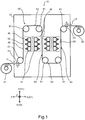
- Fig. 1 and Fig. 2 are diagrams each showing an inside of an electrospinning apparatus 10 (hereinafter, simply called an apparatus 10) according to the embodiment.
- Fig. 3 is a diagram showing an electrospinning head 31 (hereinafter, simply called a head 31) to be used in the apparatus 10.
- the apparatus 10 is an example of an apparatus to form a fiber film on the base material 40 by a well-known electrospinning method.
- the apparatus 10 has the conveying path 64 (hereinafter, called the vertical conveying path 64) to convey the base material 40 in the Y direction.
- the head 31 discharges a raw material liquid (fiber) toward the base material 40 to be conveyed in the vertical conveying path 64.
- the fiber discharged from the head 31 flies in a spinning space S (refer to Fig. 3 ) in which the head 31 and the base material 40 are opposite to each other, reaches the base material 40, and is deposited on the base material 40.
- the fiber tries to fly while spreading also outside the spinning space S (the Z direction in Fig. 3 ).
- the spinning space S in Fig. 3 is a schematic space in order to make the description easier to understand, and an actual spinning space is not limited to the spinning space S of Fig. 3 .
- the head 31 to be used in the apparatus 10 has a control body 312a described later.
- the control body 312a suppresses spread of flight of the fiber, and controls induction of the fiber to the base material 40.
- the apparatus 10 suppresses spread of the flying fiber, and controls induction of the fiber to the base material.
- the apparatus 10 can improve quality and productivity of the fiber film, and consequently can reduce an apparatus cost.
- it is sometimes called simply flight control of the fiber to suppress spread of the flying fiber and control induction of the fiber to the base material.
- the apparatus 10 has a power source 20, head units 30, an unwinding reel 41, a winding reel 42, supports 50, and a conveying device 60.
- the power source 20 will be described.
- the power source 20 is connected to the respective heads 31 of the head unit 30 described later.
- the power source 20 applies a voltage of 30 - 50 kV for example to the head 31.
- the power source 20 is connected to the control body 312a described later of each of the heads 31.
- the power source 20 applies a voltage to the control body 312a for flight control of the fiber.
- the voltage to be applied to the control body 312a has the same polarity and the same value as those of the voltage to be applied to the head 31, for example.
- the power source 20 is used commonly as the power source for applying the voltage to the head 31, and the power source for applying the voltage to the control body 312a, but a power source for the head 31 and a power source for the control body 312a may be separate power sources, respectively.
- the head units 30 are respectively arranged at the both sides of the vertical conveying path 64 to convey the base material 40 in the Y direction of Fig. 1 , and are opposite to the base material 40 to be conveyed in the vertical conveying path 64.
- the head unit 30 may be arranged at only one side of the vertical conveying path 64, but in order to improve a forming speed of the fiber film, the head units 30 are respectively arranged at the both sides of the vertical conveying path 64.
- the head unit 30 includes one or more heads 31.
- the head unit 30 includes the three heads 31, for example, as shown in Fig. 1 .
- the apparatus 10 has the three vertical conveying paths 64 as shown in Fig. 1 . Accordingly, the apparatus 10 has a total of the four head units 30 as shown in Fig. 1 , but the number of the vertical conveying paths 64 and the number of the head units 30 are not limited to these, respectively.
- the three heads 31 of the head unit 30 are supported by the support 50, as shown in Fig. 2 , and thereby they are arranged along the vertical conveying path 64 in the vertical direction (the Y direction of Fig. 2 ).
- Intervals d1 (refer to Fig. 2 ) between the respective heads 31 may be made the same, for example.
- the respective heads 31 have the same structure. The structure of the head 31 will be described later.
- intervals d2 (refer to Fig. 2 ) between the respective heads 31 and the base material 40 are the same, for example.
- the interval d2 is determined by a discharge condition including a voltage applied by the power source 20, a kind of a raw material of the fiber in the raw material liquid, and a concentration of the raw material, and so on.
- the respective heads 31 are connected to a raw material liquid storage tank not shown, via a liquid feeding mechanism not shown.
- the raw material liquid is a solution in which a raw material of the fiber is dissolved in a solvent at a prescribed concentration.
- the raw material of the fiber is not particularly limited, and can be changed arbitrarily in accordance with the material of the fiber film to be formed.
- a polyolefin system resin, a thermoplastic resin, a thermosetting resin, and so on are quoted, for example.
- the raw material can be formed by one kind of polymer or mixed spinning of two or more kinds of polymers selected from the group consisting of polystyrene, polycarbonate, polymethyl methacrylate, polypropylene, polyethylene, polyethylene terephthalate, polybutylene terephthalate, polyamide, polyoxymethylene, polyamide-imide, polyimide, polysulfone, polyethersulfone, polyetherimide, polyether ketone, polyphenylene sulfide, modified polyphenylene ether, syndiotactic polystyrene, liquid crystal polymer, that are thermoplastic resins, a urea resin, unsaturated polyester, a phenol resin, a melamine resin, an epoxy resin that are thermosetting resins, and a copolymer containing these, and so on.
- the raw material of the fiber which can be applied to the present embodiment is not limited to the listed raw materials.
- the listed raw materials of the fiber are just exempl
- the solvent may be used as long as it can dissolve the raw material of the fiber.
- the solvent can be changed arbitrarily in accordance with the raw material of the fiber to be dissolved.
- a volatile organic solvent such as an alcohol system solvent and an aromatic system solvent, or water can be used.
- the organic solvent specifically, isopropanol, ethylene glycol, cyclohexanone, dimethylformamide, acetone, ethyl acetate, dimethylacetamide, N-methyl-2-pyrolidone, hexane, toluene, xylene, methyl ethyl ketone, diethyl ketone, butyl acetate, tetrahydrofuran, dioxane, pyridine, and so on are quoted, for example.
- the solvent may be one kind of solvent, or mixture of plural kinds of solvents, selected from the listed solvents.
- the solvent which can be applied to the present embodiment is not limited to the listed solvents. The listed solvents are just exemplified.
- the head units 30 discharge the charged raw material liquids from the heads 31 described later to simultaneously form the fiber films on the both surfaces of the base material 40 to be conveyed in the vertical conveying path 64, respectively.
- the raw material liquid is fed to each of the heads 31 of the head unit 30 from the raw material liquid storage tank via the liquid feeding mechanism.
- the voltage is applied to the head 31 by the power source 20.
- the head 31 discharges the charged raw material liquid toward one surface of the base material 40 to be conveyed in the vertical conveying path 64.
- the solvent in the raw material liquid which has been discharged from the head 31 volatilizes in the atmosphere in the apparatus 10.
- the raw material (fiber) in the raw material liquid which has been discharged from the head 31 flies and reaches the one surface of the base material 40 to be conveyed in the vertical conveying path 64, and thereby the fiber film is formed on each of the both surfaces of the base material 40.
- the unwinding reel 41 and the winding reel 42 are rotated by a drive source not shown.
- the unwinding reel 41 feeds the base material 40 into a chassis 13, via an inlet port 11 of the chassis 13 of the apparatus 10 (refer to an arrow A of Fig. 1 ).
- the winding reel 42 recovers the base material 40 formed with the fiber films to be discharged from an outlet port 12 of the chassis 13 (refer to an arrow B of Fig. 1 ).
- the base material 40 is a sheet-like electrode, for example. Aluminum is quoted as the material of the base material 40, for example.
- the base material 40 which has been fed in the apparatus 10 is extended among a plurality of rollers 61 of the conveying device 60, and thereby is conveyed via the vertical conveying path 64.
- the base material 40 is discharged outside the apparatus 10 from the outlet port 12 (refer to the arrow B of Fig. 1 ), and is recovered by the winding reel 42.
- the support 50 supports the head unit 30 opposite to the base material 40 to be conveyed in one vertical conveying path 64, and the head unit 30 opposite to the base material 40 to be conveyed in the other vertical conveying path 64.
- the conveying device 60 In order to convey the base material 40, the conveying device 60 has a plurality of the rollers 61 and the drive source 62 (refer to Fig. 10 ).
- the plurality of rollers 61 are arranged at the prescribed positions in the apparatus 10 and support the base material 40, to form a plurality of horizontal conveying paths 63 to convey the base material 40 in the X1 direction, and a plurality of the vertical conveying paths 64 to convey the base material 40 in the Y direction.
- each of the horizontal conveying paths 63 is connected to the both end portions in the Y direction of the vertical conveying paths 64.
- the four horizontal conveying paths 63 are formed by the rollers 61, as shown in Fig. 1 .
- the horizontal conveying paths 63 include one conveying path to convey the base material 40 to be fed from the inlet port 11 to the first vertical conveying path 64.
- the horizontal conveying paths 63 include two conveying paths each of which conveys the base material 40 that has passed through the one vertical conveying path 64 to the next vertical conveying path 64.
- the horizontal conveying paths 63 include one conveying path to convey the base material 40 which has passed through the last vertical conveying path 64 to the outlet port 12.
- the first horizontal conveying path 63 which conveys the base material 40 to be fed from the inlet port 11 connects to the lower end portion (the end portion in the Y2 direction of Fig. 1 ) of the vertical conveying path 64.
- the next and following horizontal conveying paths 63 alternately connect to the upper end portions (the end portion in the Y1 direction of Fig. 1 ) and the lower end portions of the two opposing vertical conveying paths 64, and the last horizontal conveying path 63 connects to the upper end portion of the vertical conveying path 64.
- the three vertical conveying paths 64 are formed by the rollers 61, as shown in Fig. 1 .
- Each of the vertical conveying paths 64 connects to the horizontal conveying paths 63, as described above.
- the first vertical conveying path 64 conveys the base material 40 toward the Y1 direction.
- the next vertical conveying path 64 conveys the base material 40 toward the Y2 direction, and the further next vertical conveying path 64 changes the direction thereof to the Y1 direction and conveys the base material 40 toward the Y1 direction.
- the number of the vertical conveying paths 64, the number of the horizontal conveying paths 63 and the number of the rollers 61 are not limited to the numbers of the present embodiment, respectively.
- the drive source 62 has a motor to rotate a plurality of the rollers 61.
- the drive source 62 may have a plurality of motors for rotating a plurality of the rollers 61, respectively, or may have one common motor.
- the electrospinning apparatus of the present embodiment is not limited to the apparatus 10, but according to the apparatus 10, it is possible to provide a plurality of the vertical conveying paths 64 of the base material 40 on which the fiber is to be discharged, in a limited space of the apparatus, as described above. Further, it is possible to simultaneously form the fiber films respectively on the both surface of the base material 40, in the vertical conveying path 64. Accordingly, it is possible to miniaturize the apparatus 10, and also it is possible to improve a forming speed of the fiber film.
- the head 31 has one or more nozzle units 311, and electric field control units 312.
- the number of the nozzle units 311 can be changed arbitrarily in accordance with a width of the base material 40, and so on.
- the head 31 shown in Fig. 3 has the six nozzle units 311, for example.
- the nozzle units 311 are arranged in the width direction of the base material 40 within the range of the width of the base material 40.
- the width of the base material 40 is a width thereof in the Z direction in Fig. 1 , for example.
- Each of the nozzle units 311 has a nozzle 311a, a mounting body 311b, and a main body 311c.
- the nozzle 311a is conductive and is resistant to the raw material liquid.
- the nozzle 311a has a needle-like shape extending in a direction facing the base material 40, for example.
- the nozzles 311a are arranged in parallel when seen from the Y direction, and in a line in the Z direction with a pitch p (refer to Fig. 3 and Fig. 4 , for example).
- a plurality of the nozzles 311 are arranged not only in a line, but may be arranged in a plurality of lines.
- the nozzle 311a has an opening for discharging the raw material liquid (fiber) toward the base material 40 at one end (hereinafter, sometimes called a tip) facing the base material 40.
- the nozzle 311a has a space that is a flow path of the raw material liquid not shown inside thereof.
- the nozzle 311a is mounted on the mounting body 311b at the other end.
- the nozzle 311a is connected to the power source 20 via the mounting body 311b and the main body 311c, and is applied with a voltage.
- the shape of the nozzle 311a is not limited to a needle-like shape, but it is made to have a needle-like shape, and thereby electric field concentration becomes easy to occur at the tip of the nozzle 311a.
- the electric field concentration occurs at the tip of the nozzle 311a, it is possible to enhance a strength of the electric field occurring between the nozzle 311a and the base material 40. Accordingly, it is possible to lower the voltage to be applied by the power source 20.
- the tip of the nozzle 311a is sharpened, and thereby the electric field strength at the tip of the nozzle 311a can be concentrated, and accordingly, the nozzle 311a may have a cone shape with a sharp tip, for example.
- the mounting body 311b will be described below.
- the mounting body 311b is detachably mounted on the main body 311c at a side opposite to a side on which the nozzle 311a is mounted, for example (refer to Fig. 3 , for example).
- the main body 311c will be described below.
- the main body 311c is conductive and is resistant to the raw material liquid.
- the main body 311c has four side surfaces extending in the Z direction (the width direction of the base material 40) as shown in Fig. 4 to Fig. 5 , and is formed by a prism body having a quadrangular cross section shape (hereinafter simply called a quadrangular prism) as shown in Fig. 6 .
- the main body 311c is fixed to a mounting portion not shown so that one side surface 311x out of the four side surfaces faces the base material 40.
- the nozzle 311a is mounted on the side surface 311x via the mounting body 311b.
- the main body 311c has a space that is a flow path of the raw material liquid not shown inside thereof.
- the flow path inside the main body 311c communicates with the flow path inside the mounting body 311b.
- the raw material liquid is fed to the flow path inside the main body 311c via the liquid feeding mechanism.
- main body 311c of the present embodiment is commonly used as the main bodies of a plurality of the nozzle units 311, but a plurality of the main bodies 311c may be provided respectively for a plurality of the nozzle units 311.
- the side surface of the main body 311c on which a plurality of the nozzles 311a are arranged is not limited to one side surface thereof.
- a plurality of the nozzles 311a may be arranged on each of the two different side surfaces of the main body 311c.
- the main body 311c is fixed to a mounting portion not shown so that the two side surfaces thereof face the base material 40 side.
- the shape of the main body 311c may be a polygonal prism other than a quadrangular prism.
- the head 31 in which the nozzles 311a are arranged on each of two side surfaces 311y, 311z of the main body 311c having a shape of a polygonal prism other than a quadrangular prism will be described, with reference to Fig. 7 to Fig. 9 .
- the main body 311c has a plurality of portions 315 in each of which an apex portion is chamfered so that the electric field does not concentrate at a plurality of the apex portions between the different side surfaces.
- the side surfaces 311y, 311z are located while sandwiching the chamfered portion 315 therebetween.
- the nozzles 311a are arranged in a line in the Z direction in each of the side surface 311y, 311z of the main body 311c. That is, the head 31 has a total of two nozzle lines.
- a plurality of the nozzles 311a to be arranged on the side surface 311y is sometimes called a first nozzle line 313.
- a plurality of the nozzles 311a to be arranged on the side surface 311z is sometimes called a second nozzle line 314.
- the nozzles 311a which belong to the first nozzle line 313 are sometimes called first nozzles 313a.
- the nozzles 311a which belong to the second nozzle line 314 are sometimes called second nozzles 314a.
- Positions of a plurality of the first nozzles 313a belonging to the first nozzle line 313 and positions of a plurality of the second nozzles 314a belonging to the second nozzle line 314 are respectively different in the Z direction as shown in Fig. 7 and Fig. 8 .
- a plurality of the first nozzles 313a belonging to the first nozzle line 313 and a plurality of the second nozzles 314a belonging to the second nozzle line 314 can be arranged respectively at positions deviated from each other by 1/2 pitch (p/2) as shown in Fig. 8 .
- the positions of the first nozzles 313a and the second nozzles 314a are deviated in this manner, and thereby the fiber to be formed by the raw material liquid to be discharged from the second nozzle 314a belonging to the second nozzle line 314 can be deposited, between an area in the base material 40 on which the fiber is to be deposited by the raw material liquid to be discharged from the one first nozzle 313a belonging to the first nozzle line 313, and an area in the base material 40 on which the fiber is to be deposited by the raw material liquid to be discharged from the first nozzle 313a adjacent to the relevant one first nozzle 313a.
- the pitch p of a plurality of the first nozzles 313a in the first nozzle line 313 and the pitch p of a plurality of the second nozzles 314a in the second nozzle line 314 can be made longer, it is possible to suppress electric field interference between the tips of a plurality of the first nozzles 313a in the first nozzle line 313, and electric field interference between the tips of a plurality of the second nozzles 314a in the second nozzle line 314. Further, it is possible to suppress electric field interference between the tip of the first nozzle 313a belonging to the first nozzle line 313, and the tip of the second nozzle 314a belonging to the second nozzle line 314. As a result, it is possible to stabilize formation of the fiber film on the base material 40.
- the first nozzles 313a belonging to the first nozzle line 313 are arranged in parallel with each other when seen from the Y direction.
- the second nozzles 314a belonging to the second nozzle line 314 are arranged in parallel with each other when seen from the Y direction.
- the first nozzles 313a belonging to the first nozzle line 313 and the second nozzles 314a belonging to the second nozzle line 314 are arranged in parallel with each other when seen from the Y direction.
- a direction in which a plurality of the second nozzles 314a belonging to the second nozzle line 314 extend intersects with a direction in which a plurality of the first nozzles 313a belonging to the first nozzle line 313 extend.
- a plurality of the second nozzles 314a belonging to the second nozzle line 314 extend to more separate from a plurality of the first nozzles 313a belonging to the first nozzle line 313, as approaching the tip sides, respectively.
- a distance d5 projected in the Z direction between the tips of a plurality of the first nozzles 313a belonging to the first nozzle line 313, and the tips of a plurality of the second nozzles 314a belonging to the second nozzle line 314 is longer than a cross sectional dimension d6 of the main body 311c.
- the first nozzle line 313 and the second nozzle line 314 are configured as described above, and thereby the above-described distance d5 when seen from the Z direction can be made longer than a case in which a plurality of the first nozzle 313a belonging to the first nozzle line 313, and a plurality of the second nozzles 314a belonging to the second nozzle line 314 are arranged in parallel with each other.
- an angle ⁇ 1 (refer to Fig. 9 ) projected in the Z direction between a direction in which a plurality of the first nozzles 313a belonging to the first nozzle line 313 extend, and a direction in which a plurality of the second nozzle 314a belonging to the second nozzle line 314 extend is not less than 30°and not more than 150°. That is, that the angle ⁇ 1 is set to not less than 30°and not more than 150° is suitable for realizing miniaturization of the head 31, suppression of the electric field interference between the first nozzle line 313 and the second nozzle line 314, and stable formation of the fiber film on the base material 40. Further, in order to improve volatility of the raw material liquid, and in a case in which a plurality of heads 31 are arranged, it is more preferable that the angle ⁇ 1 is set to not less than 45° and not more than 75°.
- a distance d7 (refer to Fig. 9 ) projected in the Z direction between the end portions at the mounting bodies 311b sides of a plurality of the first nozzles 313a belonging to the first nozzle line 313, and the end portions at the mounting bodies 311b sides of a plurality of the second nozzles 314a belonging to the second nozzle line 314 can be made shorter than the above-described distance d5 (refer to Fig. 9 ). Accordingly, it becomes easy to make the cross sectional dimension d6 of the main body 311c (refer to Fig. 9 ) shorter than the distance d5. If the cross sectional dimension d6 of the main body 311c can be made shorter than the distance d5, it is possible to achieve miniaturization of the head 31.
- the main body 311c shown in Fig. 7 to Fig. 9 is a prism body having a cross section shape of a regular polygon.
- the cross section shape of the main body 311c is not limited, but since a regular polygon is line-symmetric, it is easy to arrange a plurality of nozzles 311a on each of a plurality of the side surfaces thereof.
- the cross section shape of the main body 311c shown in Fig. 7 to Fig. 9 is a regular hexagon, for example.
- the above-described angle ⁇ 1 becomes 60°, and thereby the angle ⁇ 1 can be made within the above-described angle range of not less than 45° and not more than 75°.
- the cross section shape of the main body 311c may be made a circular shape, and a plane portion may be provided at a portion on which the nozzles 311a are to be arranged.
- an angle formed by the side surface 311y and the side surface 311z is ⁇ 2
- nozzle 311a shown in Fig. 7 to Fig. 9 can be mounted on the main body 311c via the mounting body 311b, in the same manner as the example shown in Fig. 3 to Fig. 5 .
- the electric field control unit 312 has the control body 312a and a connecting body 312b.
- control body 312a will be described below.
- the control body 312a is conductive and is resistant to the raw material liquid.
- the control body 312a is mounted on one end of the connecting body 312b.
- the connecting body 312b is mounted on the main body 311c of the nozzle unit 311, as described later.
- the main body 311c is connected to the power source 20 as described above.
- control body 312a is applied with the voltage having the same polarity and the same value as those of the voltage to be applied to nozzle 311a by the power source 20, via the main body 311c and the connecting body 312b.
- control bodies 312a are mounted on the connecting bodies 312b, and thereby the control bodies 312a are arranged at the both ends in the Z direction of the head 31 (refer to Fig. 3 , for example).
- control body 312a is arranged in the vicinity of the outermost nozzle unit 311 out of a plurality of the nozzle units 311 arranged in the Z direction. Specifically, the control body 312a is arranged adjacent to the nozzle 311a included in the outermost nozzle unit 311 with an interval d3 (refer to Fig. 4 ).
- the interval d3 is not less than the pitch p of the respective nozzles 311a.
- the interval d3 becomes narrower than the pitch p, electric field interference occurs between the control body 312a and the nozzle 311a.
- control body 312a is arranged so as to extend in the outside direction of the spinning space S (refer to Fig. 3 ) in which the tips of the nozzles 311a are opposite to the base material 40, and in the width direction (the Z direction) of the base material 40.
- the direction in which the control body 312a extends toward the outside of the spinning space S is substantially orthogonal to the direction (refer to the X direction in Fig. 3 , for example) in which the nozzle 311a extends toward the base material 40, for example.
- To be substantially orthogonal includes a range of ⁇ 5° with respect to a direction orthogonal to the direction in which the nozzles 311a extends toward the base material 40.
- control body 312 when the control body 312 is nearer to the base material 40 than the tip of the nozzle 311a, a possibility of breakdown occurs. Accordingly, the control body 312a is mounted on the connecting body 312b, and thereby the control body 312a is arranged to have a height h ( ⁇ 0) from the tip of the nozzle 311a (refer to Fig. 3 ).
- the control body 312a has a length L (for example, refer to Fig. 3 ) in the direction in which the control body 312a extends toward the outside of the spinning space S.
- the length L is preferably not less than 3/20 of a distance d2 between the tip of the nozzle 311a and the base material 40, and is more preferably not less than 3/10 of the distance d2.
- the control body 312a has a width W in the direction orthogonal to the direction of the length L (refer to Fig. 4 ).
- the width W is not particularly limited. Accordingly, the control body 312a may be a plate-like member as shown in Fig. 4 , or may be a rod-like member, for example. However, in the case of the head 31 shown in Fig. 7 to fig. 9 , the control body 312a has a width not less than the above-described distance d5 (refer to Fig. 9 ) so as to obtain a suitable effect of flight control of the fiber.
- the connecting body 312b is a plate-like member, for example, and is conductive and is resistant to the raw material liquid.
- the connecting bodies 312b are mounted on the both ends of the main body 311c of the nozzle unit 311, at the other end sides opposite to one ends on which the control bodies 312a are mounted.
- the connecting bodies 312b are mounted on the main body 311c, and thereby the control bodies 312a are arranged at the above-described positions and in the above-described directions.
- the connecting body 312b electrically connects the main body 311c of the nozzle unit 311 and the control body 312a. Accordingly, the power source 20 to apply the voltage to the nozzle unit 311 can be commonly used as a power source to apply the voltage to the control body 312a.
- a support for arranging the control body 312a as described above may be provided, in place of the control body 312b.
- a terminal for applying the voltage to the control body 312a may be provided, in place of the connecting body 312b.
- control body 312a and the connecting body 312b are separate members.
- control body 312a and the connecting body 312b may be formed by binding an identical member.
- control body 312a of the control unit 312 is applied with the voltage by the power source 20, and thereby the control body 312a makes an electric field to be generated at the periphery of each of the both end portions of the head 31 (at the peripheries of the outermost nozzle units 311).
- the fiber to be discharged from the head 31 flies in the direction of the base material 40 to be conveyed in the vertical conveying path 64, and also tries to fly in the width direction (refer to the Z direction of Fig. 3 ) of the base material 40 other than the direction of the base material 40 to be conveyed in the vertical conveying path 64.
- control body 312a makes the electric field to be generated at the periphery of each of the both end portions of the head 31, and thereby the control body 312a suppresses spread of flight of the fiber to be discharged from the head 31 (the nozzle 311a) in the width direction of the base material 40, and controls the fiber so as to be induced to the base material 40.
- control body 312a suppresses flight of the fiber to the outside (the Z direction side) from the spinning space S between the head 31 and the base material 40 in Fig. 3 .
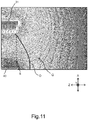
- Fig. 11 is a simulation diagram showing a distribution of equipotential lines Q in the spinning space S in the case in which the control body 312a is not arranged, and at the periphery of the outside thereof.
- Fig. 12 is a simulation diagram showing a distribution of equipotential lines Q in the spinning space S in the case in which a conventional electric field control unit 411 is arranged in place of the control body 312a, and at the periphery of the outside thereof.
- the conventional electric field control unit 411 is a plate-like member extending in the same direction as the direction (the X direction) in which the nozzle 311a extends.
- Fig. 13 is a simulation diagram showing a distribution of equipotential lines Q in the spinning space S in the case in which the control body 312a according to the present embodiment is arranged, and at the periphery of the outside thereof.
- Fig. 10 is a block diagram showing an example of a control configuration of the apparatus 10.
- the apparatus 10 has a control device 80.
- the power source 20 and the drive source 62 which have been described above, for example, and a liquid feeding mechanism not shown, and so on are connected to the control device 80.
- the control device 80 includes a processor 81 and a memory 82.
- the processor 81 includes a CPU, or an MPU, for example.
- the memory 82 includes a ROM 82a and a RAM 82b, for example.
- the processor 81 controls the whole operation of the apparatus 10.
- the ROM 82a stores a control program and so on for a control operation by the processor 81, for example.
- the RAM 82b provides a work area for developing the control program and so on read from the ROM 82a, for example.
- the processor 81 reads the control program stored in the ROM 82a, and develops the control program in the RAM 82b.
- the processor 81 controls the power source 20 and the liquid feeding mechanism not shown, and so on, in accordance with the control program, in order to make the raw material liquid to be discharged from the head unit 30.
- the processor 81 controls the drive source 62, in accordance with the control program, in order to convey the base material 40. Further, the processor 81 controls the power source 20, in accordance with the control program, in order to apply the voltage to the control body 312a.
- the head 31 has the control body 312a which is arranged in the vicinity of the outermost nozzle unit 311 in the width direction of the base material 40, and extends toward the outside of the spinning space S between the nozzle unit 311 and the base material 40.
- the control body 312a is applied with the voltage of the same polarity as the voltage to be applied to the nozzle unit 311, and thereby makes the electric field to be generated at the periphery of the end portion of the head 31 (at the periphery of the outermost nozzle unit 311).
- spread of flight of the fiber to be discharged from the nozzle unit 311 can be suppressed, and the induction of the fiber to the base material 40 can be controlled, by the control body 312a.
Landscapes
- Engineering & Computer Science (AREA)
- Textile Engineering (AREA)
- Mechanical Engineering (AREA)
- Chemical & Material Sciences (AREA)
- Chemical Kinetics & Catalysis (AREA)
- General Chemical & Material Sciences (AREA)
- Spinning Methods And Devices For Manufacturing Artificial Fibers (AREA)
- Nonwoven Fabrics (AREA)
Abstract
Description
- This application is based upon and claims the benefit of priority from the prior Japanese Patent Application No.
2018-081332, filed on April 20, 2018 - Embodiments described herein generally relate to an electrospinning head, and an electrospinning apparatus using an electrospinning head.
- Conventionally, an electrospinning apparatus which forms a fiber film on a base material using an electrospinning method is known. The conventional apparatus discharges a raw material liquid (fiber) toward the base material from an electrospinning head (hereinafter, simply called a head), while conveying the base material.
- The above-described apparatus, in order to control spread of the fiber which has been discharged from the head and is flying, in the width direction of the base material, has control units which are arranged at the both ends of the head and extend in the base material direction from the head.
- Further, the conventional apparatus, in order to induce the fiber the spread of which has been controlled by the control units onto the base material, has induction units which are respectively provided between the control units and the base material.
-
-
Fig. 1 is a diagram showing an electrospinning apparatus according to an embodiment. -
Fig. 2 is a partially enlarged diagram schematically showing a structure at the periphery of the head unit of the apparatus shown inFig. 1 . -
Fig. 3 is a side view which is seen from the direction orthogonal to the width direction of the base material, and shows an example of the electrospinning head according to the embodiment. -
Fig. 4 is a perspective view showing the end portion of the head shown inFig. 3 . -
Fig. 5 is an enlarged side view showing the end portion of the head shown inFig. 3 . -
Fig. 6 is a side view of the head shown inFig. 3 which is seen from the width direction of the base material. -
Fig. 7 is a perspective view showing another example of a head according to the embodiment. -
Fig. 8 is a side view showing the end portion of the head shown inFig. 7 which is seen from the direction orthogonal to the width direction of the base material. -
Fig. 9 is a side view of the head shown inFig. 7 which is seen from the width direction of the base material. -
Fig. 10 is a block diagram showing an example of a control configuration of the apparatus according to the embodiment. -
Fig. 11 is a simulation diagram showing equipotential lines at an end portion of a head according to a comparative example of the embodiment. -
Fig. 12 is a simulation diagram showing equipotential lines at an end portion of a head according to a comparative example of the embodiment. -
Fig. 13 is a simulation diagram showing equipotential lines at the end portion of the head according to the embodiment. - According to one embodiment, an electrospinning head has a nozzle unit and a control body. The nozzle unit is arranged opposite to a base material, is applied with a voltage, and thereby is capable of discharging a raw material liquid of fiber. The control body is arranged in the vicinity of the nozzle unit so as to extend to an outside of a spinning space between the base material and the nozzle unit. Further, the control body is applied with a voltage of the same polarity as the voltage to be applied to the nozzle unit, and thereby is capable of making an electric field to be generated at the periphery of the nozzle unit.
- Hereinafter, embodiments will be described, with reference to the drawings. In addition, X, Y, Z directions in the respective drawings are common directions throughout the whole drawings, and are directions orthogonal to each other. In addition, the X direction is a direction in which a
nozzle 311a extends toward abase material 40, and an X1 direction is a conveying direction of thebase material 40 in a horizontal conveying path. In addition, the Y direction is a direction orthogonal to a width direction of thebase material 40, and is a conveying direction of thebase material 40 in avertical conveying path 64. In addition, the Z direction is the width direction of thebase material 40, and is a direction in whichnozzles 311a ofnozzle units 311 included in ahead 31 are arranged. - To begin with, the whole of the embodiment will be schematically described.
Fig. 1 andFig. 2 are diagrams each showing an inside of an electrospinning apparatus 10 (hereinafter, simply called an apparatus 10) according to the embodiment.Fig. 3 is a diagram showing an electrospinning head 31 (hereinafter, simply called a head 31) to be used in theapparatus 10. - The
apparatus 10 is an example of an apparatus to form a fiber film on thebase material 40 by a well-known electrospinning method. Theapparatus 10 has the conveying path 64 (hereinafter, called the vertical conveying path 64) to convey thebase material 40 in the Y direction. Thehead 31 discharges a raw material liquid (fiber) toward thebase material 40 to be conveyed in thevertical conveying path 64. - Here, the fiber discharged from the
head 31 flies in a spinning space S (refer toFig. 3 ) in which thehead 31 and thebase material 40 are opposite to each other, reaches thebase material 40, and is deposited on thebase material 40. On the other hand, the fiber tries to fly while spreading also outside the spinning space S (the Z direction inFig. 3 ). - Accordingly, in order to surely deposit the fiber on the
base material 40 to form a fiber film, it is necessary to control spread of flight of the fiber, and to induce the flying fiber onto thebase material 40. In addition, the spinning space S inFig. 3 is a schematic space in order to make the description easier to understand, and an actual spinning space is not limited to the spinning space S ofFig. 3 . - Meanwhile, the
head 31 to be used in theapparatus 10 has acontrol body 312a described later. Thecontrol body 312a suppresses spread of flight of the fiber, and controls induction of the fiber to thebase material 40. - Accordingly, according to the present embodiment, though having a simple configuration, the
apparatus 10 suppresses spread of the flying fiber, and controls induction of the fiber to the base material. Thereby theapparatus 10 can improve quality and productivity of the fiber film, and consequently can reduce an apparatus cost. In addition, in the following description, it is sometimes called simply flight control of the fiber to suppress spread of the flying fiber and control induction of the fiber to the base material. - Next, respective portions of the
apparatus 10 will be described in detail, with reference toFig. 1 ,Fig. 2 andFig. 10 . Theapparatus 10 has apower source 20,head units 30, anunwinding reel 41, awinding reel 42, supports 50, and aconveying device 60. - To begin with, the
power source 20 will be described. Thepower source 20 is connected to therespective heads 31 of thehead unit 30 described later. In order to charge the raw material liquid to be fed to each of theheads 31, thepower source 20 applies a voltage of 30 - 50 kV for example to thehead 31. - In addition, the
power source 20 is connected to thecontrol body 312a described later of each of theheads 31. Thepower source 20 applies a voltage to thecontrol body 312a for flight control of the fiber. The voltage to be applied to thecontrol body 312a has the same polarity and the same value as those of the voltage to be applied to thehead 31, for example. - In the present embodiment, the
power source 20 is used commonly as the power source for applying the voltage to thehead 31, and the power source for applying the voltage to thecontrol body 312a, but a power source for thehead 31 and a power source for thecontrol body 312a may be separate power sources, respectively. - Next, the
head unit 30 will be described. Thehead units 30 are respectively arranged at the both sides of thevertical conveying path 64 to convey thebase material 40 in the Y direction ofFig. 1 , and are opposite to thebase material 40 to be conveyed in thevertical conveying path 64. Thehead unit 30 may be arranged at only one side of thevertical conveying path 64, but in order to improve a forming speed of the fiber film, thehead units 30 are respectively arranged at the both sides of thevertical conveying path 64. - The
head unit 30 includes one ormore heads 31. In the present embodiment, thehead unit 30 includes the threeheads 31, for example, as shown inFig. 1 . - In addition, in the present embodiment, the
apparatus 10 has the threevertical conveying paths 64 as shown inFig. 1 . Accordingly, theapparatus 10 has a total of the fourhead units 30 as shown inFig. 1 , but the number of thevertical conveying paths 64 and the number of thehead units 30 are not limited to these, respectively. - In addition, the three
heads 31 of thehead unit 30 are supported by thesupport 50, as shown inFig. 2 , and thereby they are arranged along thevertical conveying path 64 in the vertical direction (the Y direction ofFig. 2 ). Intervals d1 (refer toFig. 2 ) between therespective heads 31 may be made the same, for example. In addition, therespective heads 31 have the same structure. The structure of thehead 31 will be described later. - In addition, intervals d2 (refer to
Fig. 2 ) between therespective heads 31 and thebase material 40 are the same, for example. The interval d2 is determined by a discharge condition including a voltage applied by thepower source 20, a kind of a raw material of the fiber in the raw material liquid, and a concentration of the raw material, and so on. - In addition, the
respective heads 31 are connected to a raw material liquid storage tank not shown, via a liquid feeding mechanism not shown. The raw material liquid is a solution in which a raw material of the fiber is dissolved in a solvent at a prescribed concentration. - The raw material of the fiber is not particularly limited, and can be changed arbitrarily in accordance with the material of the fiber film to be formed. As the raw material of the fiber, a polyolefin system resin, a thermoplastic resin, a thermosetting resin, and so on are quoted, for example. As a specific example, the raw material can be formed by one kind of polymer or mixed spinning of two or more kinds of polymers selected from the group consisting of polystyrene, polycarbonate, polymethyl methacrylate, polypropylene, polyethylene, polyethylene terephthalate, polybutylene terephthalate, polyamide, polyoxymethylene, polyamide-imide, polyimide, polysulfone, polyethersulfone, polyetherimide, polyether ketone, polyphenylene sulfide, modified polyphenylene ether, syndiotactic polystyrene, liquid crystal polymer, that are thermoplastic resins, a urea resin, unsaturated polyester, a phenol resin, a melamine resin, an epoxy resin that are thermosetting resins, and a copolymer containing these, and so on. In addition, the raw material of the fiber which can be applied to the present embodiment is not limited to the listed raw materials. The listed raw materials of the fiber are just exemplified.
- The solvent may be used as long as it can dissolve the raw material of the fiber. The solvent can be changed arbitrarily in accordance with the raw material of the fiber to be dissolved. As the solvent, a volatile organic solvent such as an alcohol system solvent and an aromatic system solvent, or water can be used. As the organic solvent, specifically, isopropanol, ethylene glycol, cyclohexanone, dimethylformamide, acetone, ethyl acetate, dimethylacetamide, N-methyl-2-pyrolidone, hexane, toluene, xylene, methyl ethyl ketone, diethyl ketone, butyl acetate, tetrahydrofuran, dioxane, pyridine, and so on are quoted, for example. In addition, the solvent may be one kind of solvent, or mixture of plural kinds of solvents, selected from the listed solvents. In addition, the solvent which can be applied to the present embodiment is not limited to the listed solvents. The listed solvents are just exemplified.
- With the above-described configuration, the
head units 30 discharge the charged raw material liquids from theheads 31 described later to simultaneously form the fiber films on the both surfaces of thebase material 40 to be conveyed in the vertical conveyingpath 64, respectively. - That is, to begin with, the raw material liquid is fed to each of the
heads 31 of thehead unit 30 from the raw material liquid storage tank via the liquid feeding mechanism. In addition, the voltage is applied to thehead 31 by thepower source 20. - The
head 31 discharges the charged raw material liquid toward one surface of thebase material 40 to be conveyed in the vertical conveyingpath 64. The solvent in the raw material liquid which has been discharged from thehead 31 volatilizes in the atmosphere in theapparatus 10. - The raw material (fiber) in the raw material liquid which has been discharged from the
head 31 flies and reaches the one surface of thebase material 40 to be conveyed in the vertical conveyingpath 64, and thereby the fiber film is formed on each of the both surfaces of thebase material 40. - In addition, a part of the fiber which has been discharged from the
head 31 tries to fly also in the width direction (the Z direction ofFig. 1 ) of thebase material 40 to be conveyed in the vertical conveyingpath 64. But flight control of the fiber is performed by thecontrol body 312a, as described later. - Next, the unwinding
reel 41 and the windingreel 42 will be described. The unwindingreel 41 and the windingreel 42 are rotated by a drive source not shown. The unwindingreel 41 feeds thebase material 40 into achassis 13, via aninlet port 11 of thechassis 13 of the apparatus 10 (refer to an arrow A ofFig. 1 ). The windingreel 42 recovers thebase material 40 formed with the fiber films to be discharged from anoutlet port 12 of the chassis 13 (refer to an arrow B ofFig. 1 ). In addition, thebase material 40 is a sheet-like electrode, for example. Aluminum is quoted as the material of thebase material 40, for example. - The
base material 40 which has been fed in theapparatus 10 is extended among a plurality ofrollers 61 of the conveyingdevice 60, and thereby is conveyed via the vertical conveyingpath 64. - After having been formed with the fiber films by the
head units 30 arranged in the vertical conveyingpaths 64, thebase material 40 is discharged outside theapparatus 10 from the outlet port 12 (refer to the arrow B ofFig. 1 ), and is recovered by the windingreel 42. - Next, the
support 50 will be described. As shown inFig. 2 , thesupport 50 supports thehead unit 30 opposite to thebase material 40 to be conveyed in one vertical conveyingpath 64, and thehead unit 30 opposite to thebase material 40 to be conveyed in the other vertical conveyingpath 64. - Next, the conveying
device 60 will be described. In order to convey thebase material 40, the conveyingdevice 60 has a plurality of therollers 61 and the drive source 62 (refer toFig. 10 ). - The plurality of
rollers 61 are arranged at the prescribed positions in theapparatus 10 and support thebase material 40, to form a plurality of horizontal conveyingpaths 63 to convey thebase material 40 in the X1 direction, and a plurality of the vertical conveyingpaths 64 to convey thebase material 40 in the Y direction. - In order to feed the
base material 40 to the vertical conveyingpath 64, and convey thebase material 40 which has passed through the vertical conveyingpath 64 and has been formed with the fiber film to the next vertical conveyingpath 64 or outside theapparatus 10, each of the horizontal conveyingpaths 63 is connected to the both end portions in the Y direction of the vertical conveyingpaths 64. - In the present embodiment, the four horizontal conveying
paths 63 are formed by therollers 61, as shown inFig. 1 . Specifically, the horizontal conveyingpaths 63 include one conveying path to convey thebase material 40 to be fed from theinlet port 11 to the first vertical conveyingpath 64. - In addition, the horizontal conveying
paths 63 include two conveying paths each of which conveys thebase material 40 that has passed through the one vertical conveyingpath 64 to the next vertical conveyingpath 64. - Further, the horizontal conveying
paths 63 include one conveying path to convey thebase material 40 which has passed through the last vertical conveyingpath 64 to theoutlet port 12. - In the present embodiment, the first horizontal conveying
path 63 which conveys thebase material 40 to be fed from theinlet port 11 connects to the lower end portion (the end portion in the Y2 direction ofFig. 1 ) of the vertical conveyingpath 64. The next and following horizontal conveyingpaths 63 alternately connect to the upper end portions (the end portion in the Y1 direction ofFig. 1 ) and the lower end portions of the two opposing vertical conveyingpaths 64, and the last horizontal conveyingpath 63 connects to the upper end portion of the vertical conveyingpath 64. - In addition, in the present embodiment, the three vertical conveying
paths 64 are formed by therollers 61, as shown inFig. 1 . Each of the vertical conveyingpaths 64 connects to the horizontal conveyingpaths 63, as described above. - Accordingly, the first vertical conveying
path 64 conveys thebase material 40 toward the Y1 direction. The next vertical conveyingpath 64 conveys thebase material 40 toward the Y2 direction, and the further next vertical conveyingpath 64 changes the direction thereof to the Y1 direction and conveys thebase material 40 toward the Y1 direction. - In addition, the number of the vertical conveying
paths 64, the number of the horizontal conveyingpaths 63 and the number of therollers 61 are not limited to the numbers of the present embodiment, respectively. - The
drive source 62 has a motor to rotate a plurality of therollers 61. Thedrive source 62 may have a plurality of motors for rotating a plurality of therollers 61, respectively, or may have one common motor. - In addition, the electrospinning apparatus of the present embodiment is not limited to the
apparatus 10, but according to theapparatus 10, it is possible to provide a plurality of the vertical conveyingpaths 64 of thebase material 40 on which the fiber is to be discharged, in a limited space of the apparatus, as described above. Further, it is possible to simultaneously form the fiber films respectively on the both surface of thebase material 40, in the vertical conveyingpath 64. Accordingly, it is possible to miniaturize theapparatus 10, and also it is possible to improve a forming speed of the fiber film. - Next, a plurality of the
heads 31 included in thehead unit 30 will be described in detail, with reference toFig. 3 to Fig. 6 . In addition, since therespective heads 31 have the same structure, the onehead 31 will be described in the following description. - As shown in
Fig. 3 , thehead 31 has one ormore nozzle units 311, and electricfield control units 312. - The number of the
nozzle units 311 can be changed arbitrarily in accordance with a width of thebase material 40, and so on. Thehead 31 shown inFig. 3 has the sixnozzle units 311, for example. Thenozzle units 311 are arranged in the width direction of thebase material 40 within the range of the width of thebase material 40. The width of thebase material 40 is a width thereof in the Z direction inFig. 1 , for example. - Each of the
nozzle units 311 has anozzle 311a, a mountingbody 311b, and amain body 311c. - To begin with, the
nozzle 311a will be described below. Thenozzle 311a is conductive and is resistant to the raw material liquid. Thenozzle 311a has a needle-like shape extending in a direction facing thebase material 40, for example. Thenozzles 311a are arranged in parallel when seen from the Y direction, and in a line in the Z direction with a pitch p (refer toFig. 3 andFig. 4 , for example). In addition, a plurality of thenozzles 311 are arranged not only in a line, but may be arranged in a plurality of lines. - The
nozzle 311a has an opening for discharging the raw material liquid (fiber) toward thebase material 40 at one end (hereinafter, sometimes called a tip) facing thebase material 40. Thenozzle 311a has a space that is a flow path of the raw material liquid not shown inside thereof. Thenozzle 311a is mounted on the mountingbody 311b at the other end. Thenozzle 311a is connected to thepower source 20 via the mountingbody 311b and themain body 311c, and is applied with a voltage. - In addition, the shape of the
nozzle 311a is not limited to a needle-like shape, but it is made to have a needle-like shape, and thereby electric field concentration becomes easy to occur at the tip of thenozzle 311a. When the electric field concentration occurs at the tip of thenozzle 311a, it is possible to enhance a strength of the electric field occurring between thenozzle 311a and thebase material 40. Accordingly, it is possible to lower the voltage to be applied by thepower source 20. - In addition, the tip of the
nozzle 311a is sharpened, and thereby the electric field strength at the tip of thenozzle 311a can be concentrated, and accordingly, thenozzle 311a may have a cone shape with a sharp tip, for example. - The mounting
body 311b will be described below. The mountingbody 311b is detachably mounted on themain body 311c at a side opposite to a side on which thenozzle 311a is mounted, for example (refer toFig. 3 , for example). - The
main body 311c will be described below. Themain body 311c is conductive and is resistant to the raw material liquid. Themain body 311c has four side surfaces extending in the Z direction (the width direction of the base material 40) as shown inFig. 4 to Fig. 5 , and is formed by a prism body having a quadrangular cross section shape (hereinafter simply called a quadrangular prism) as shown inFig. 6 . - The
main body 311c is fixed to a mounting portion not shown so that oneside surface 311x out of the four side surfaces faces thebase material 40. Thenozzle 311a is mounted on theside surface 311x via the mountingbody 311b. - The
main body 311c has a space that is a flow path of the raw material liquid not shown inside thereof. The flow path inside themain body 311c communicates with the flow path inside the mountingbody 311b. In addition, the raw material liquid is fed to the flow path inside themain body 311c via the liquid feeding mechanism. - In addition, the
main body 311c of the present embodiment is commonly used as the main bodies of a plurality of thenozzle units 311, but a plurality of themain bodies 311c may be provided respectively for a plurality of thenozzle units 311. - In addition, the side surface of the
main body 311c on which a plurality of thenozzles 311a are arranged is not limited to one side surface thereof. For example, a plurality of thenozzles 311a may be arranged on each of the two different side surfaces of themain body 311c. In this case, themain body 311c is fixed to a mounting portion not shown so that the two side surfaces thereof face thebase material 40 side. - In addition, the shape of the
main body 311c may be a polygonal prism other than a quadrangular prism. Hereinafter, thehead 31 in which thenozzles 311a are arranged on each of twoside surfaces main body 311c having a shape of a polygonal prism other than a quadrangular prism will be described, with reference toFig. 7 to Fig. 9 . In addition, themain body 311c has a plurality ofportions 315 in each of which an apex portion is chamfered so that the electric field does not concentrate at a plurality of the apex portions between the different side surfaces. The side surfaces 311y, 311z are located while sandwiching the chamferedportion 315 therebetween. - The
nozzles 311a are arranged in a line in the Z direction in each of theside surface main body 311c. That is, thehead 31 has a total of two nozzle lines. - Hereinafter, a plurality of the
nozzles 311a to be arranged on theside surface 311y is sometimes called afirst nozzle line 313. In addition, a plurality of thenozzles 311a to be arranged on theside surface 311z is sometimes called asecond nozzle line 314. In addition, thenozzles 311a which belong to thefirst nozzle line 313 are sometimes calledfirst nozzles 313a. Further, thenozzles 311a which belong to thesecond nozzle line 314 are sometimes calledsecond nozzles 314a. - Positions of a plurality of the
first nozzles 313a belonging to thefirst nozzle line 313 and positions of a plurality of thesecond nozzles 314a belonging to thesecond nozzle line 314 are respectively different in the Z direction as shown inFig. 7 andFig. 8 . - For example, a plurality of the
first nozzles 313a belonging to thefirst nozzle line 313 and a plurality of thesecond nozzles 314a belonging to thesecond nozzle line 314 can be arranged respectively at positions deviated from each other by 1/2 pitch (p/2) as shown inFig. 8 . - The positions of the
first nozzles 313a and thesecond nozzles 314a are deviated in this manner, and thereby the fiber to be formed by the raw material liquid to be discharged from thesecond nozzle 314a belonging to thesecond nozzle line 314 can be deposited, between an area in thebase material 40 on which the fiber is to be deposited by the raw material liquid to be discharged from the onefirst nozzle 313a belonging to thefirst nozzle line 313, and an area in thebase material 40 on which the fiber is to be deposited by the raw material liquid to be discharged from thefirst nozzle 313a adjacent to the relevant onefirst nozzle 313a. - Accordingly, even when the pitch p of a plurality of the
first nozzles 313a in thefirst nozzle line 313 and the pitch p of a plurality of thesecond nozzles 314a in thesecond nozzle line 314 are made longer, it is possible to suppress occurrence of unevenness in the fiber film to be formed on thebase material 40. In addition, this means that an apparent pitch of a plurality ofnozzles 311a in the Z direction is shortened. Accordingly, compared with a case in which the same number ofnozzles 311a are arranged in a line, in this case, it is possible to make the length of themain body 311c shorter, and accordingly, it is possible to achieve miniaturization of thehead 31. - Since the pitch p of a plurality of the
first nozzles 313a in thefirst nozzle line 313 and the pitch p of a plurality of thesecond nozzles 314a in thesecond nozzle line 314 can be made longer, it is possible to suppress electric field interference between the tips of a plurality of thefirst nozzles 313a in thefirst nozzle line 313, and electric field interference between the tips of a plurality of thesecond nozzles 314a in thesecond nozzle line 314. Further, it is possible to suppress electric field interference between the tip of thefirst nozzle 313a belonging to thefirst nozzle line 313, and the tip of thesecond nozzle 314a belonging to thesecond nozzle line 314. As a result, it is possible to stabilize formation of the fiber film on thebase material 40. - In addition, as shown in
Fig. 8 , thefirst nozzles 313a belonging to thefirst nozzle line 313 are arranged in parallel with each other when seen from the Y direction. Thesecond nozzles 314a belonging to thesecond nozzle line 314 are arranged in parallel with each other when seen from the Y direction. - In addition, as shown in
Fig. 8 , thefirst nozzles 313a belonging to thefirst nozzle line 313 and thesecond nozzles 314a belonging to thesecond nozzle line 314 are arranged in parallel with each other when seen from the Y direction. - However, as shown in
Fig. 9 , when seen from the Z direction, a direction in which a plurality of thesecond nozzles 314a belonging to thesecond nozzle line 314 extend intersects with a direction in which a plurality of thefirst nozzles 313a belonging to thefirst nozzle line 313 extend. - In addition, as shown in
Fig. 9 , when seen from the Z direction, a plurality of thesecond nozzles 314a belonging to thesecond nozzle line 314 extend to more separate from a plurality of thefirst nozzles 313a belonging to thefirst nozzle line 313, as approaching the tip sides, respectively. - In addition, as shown in
Fig. 9 , when seen from the Z direction, a distance d5 projected in the Z direction between the tips of a plurality of thefirst nozzles 313a belonging to thefirst nozzle line 313, and the tips of a plurality of thesecond nozzles 314a belonging to thesecond nozzle line 314 is longer than a cross sectional dimension d6 of themain body 311c. - The
first nozzle line 313 and thesecond nozzle line 314 are configured as described above, and thereby the above-described distance d5 when seen from the Z direction can be made longer than a case in which a plurality of thefirst nozzle 313a belonging to thefirst nozzle line 313, and a plurality of thesecond nozzles 314a belonging to thesecond nozzle line 314 are arranged in parallel with each other. - Accordingly, it is possible to suppress occurrence of electric field interference between the tips of a plurality of the
first nozzles 313a belonging to thefirst nozzle line 313, and the tips of a plurality of thesecond nozzles 314a belonging to thesecond nozzle line 314. As a result, it is possible to stabilize formation of the fiber film on thebase material 40. - It is preferable that an angle θ1 (refer to
Fig. 9 ) projected in the Z direction between a direction in which a plurality of thefirst nozzles 313a belonging to thefirst nozzle line 313 extend, and a direction in which a plurality of thesecond nozzle 314a belonging to thesecond nozzle line 314 extend is not less than 30°and not more than 150°. That is, that the angle θ1 is set to not less than 30°and not more than 150° is suitable for realizing miniaturization of thehead 31, suppression of the electric field interference between thefirst nozzle line 313 and thesecond nozzle line 314, and stable formation of the fiber film on thebase material 40. Further, in order to improve volatility of the raw material liquid, and in a case in which a plurality ofheads 31 are arranged, it is more preferable that the angle θ1 is set to not less than 45° and not more than 75°. - In addition, a distance d7 (refer to
Fig. 9 ) projected in the Z direction between the end portions at the mountingbodies 311b sides of a plurality of thefirst nozzles 313a belonging to thefirst nozzle line 313, and the end portions at the mountingbodies 311b sides of a plurality of thesecond nozzles 314a belonging to thesecond nozzle line 314 can be made shorter than the above-described distance d5 (refer toFig. 9 ). Accordingly, it becomes easy to make the cross sectional dimension d6 of themain body 311c (refer toFig. 9 ) shorter than the distance d5. If the cross sectional dimension d6 of themain body 311c can be made shorter than the distance d5, it is possible to achieve miniaturization of thehead 31. - The
main body 311c shown inFig. 7 to Fig. 9 is a prism body having a cross section shape of a regular polygon. The cross section shape of themain body 311c is not limited, but since a regular polygon is line-symmetric, it is easy to arrange a plurality ofnozzles 311a on each of a plurality of the side surfaces thereof. - The cross section shape of the
main body 311c shown inFig. 7 to Fig. 9 is a regular hexagon, for example. In this case, when thefirst nozzle line 313 is arranged on theside surface 311y of themain body 311c, and thesecond nozzle line 314 is arranged on theside surface 311z located while sandwiching the chamferedportion 315 therebetween, the above-described angle θ1 becomes 60°, and thereby the angle θ1 can be made within the above-described angle range of not less than 45° and not more than 75°. In addition, the cross section shape of themain body 311c may be made a circular shape, and a plane portion may be provided at a portion on which thenozzles 311a are to be arranged. - In addition, an angle formed by the
side surface 311y and theside surface 311z is θ2, the above-described angle θ1 can be expressed by the following expression.
- In addition, the
nozzle 311a shown inFig. 7 to Fig. 9 can be mounted on themain body 311c via the mountingbody 311b, in the same manner as the example shown inFig. 3 to Fig. 5 . - Next, the electric
field control unit 312 will be described, with reference toFig. 3 andFig. 4 . The electricfield control unit 312 has thecontrol body 312a and a connectingbody 312b. - To begin with, the
control body 312a will be described below. Thecontrol body 312a is conductive and is resistant to the raw material liquid. Thecontrol body 312a is mounted on one end of the connectingbody 312b. In addition, the connectingbody 312b is mounted on themain body 311c of thenozzle unit 311, as described later. In addition, themain body 311c is connected to thepower source 20 as described above. - Accordingly, the
control body 312a is applied with the voltage having the same polarity and the same value as those of the voltage to be applied tonozzle 311a by thepower source 20, via themain body 311c and the connectingbody 312b. - In addition, the
control bodies 312a are mounted on the connectingbodies 312b, and thereby thecontrol bodies 312a are arranged at the both ends in the Z direction of the head 31 (refer toFig. 3 , for example). - That is, the
control body 312a is arranged in the vicinity of theoutermost nozzle unit 311 out of a plurality of thenozzle units 311 arranged in the Z direction. Specifically, thecontrol body 312a is arranged adjacent to thenozzle 311a included in theoutermost nozzle unit 311 with an interval d3 (refer toFig. 4 ). - It is preferable that the interval d3 is not less than the pitch p of the
respective nozzles 311a. When the interval d3 becomes narrower than the pitch p, electric field interference occurs between thecontrol body 312a and thenozzle 311a. - Further, the
control body 312a is arranged so as to extend in the outside direction of the spinning space S (refer toFig. 3 ) in which the tips of thenozzles 311a are opposite to thebase material 40, and in the width direction (the Z direction) of thebase material 40. - The direction in which the
control body 312a extends toward the outside of the spinning space S is substantially orthogonal to the direction (refer to the X direction inFig. 3 , for example) in which thenozzle 311a extends toward thebase material 40, for example. To be substantially orthogonal includes a range of ±5° with respect to a direction orthogonal to the direction in which thenozzles 311a extends toward thebase material 40. - In addition, when the
control body 312 is nearer to thebase material 40 than the tip of thenozzle 311a, a possibility of breakdown occurs. Accordingly, thecontrol body 312a is mounted on the connectingbody 312b, and thereby thecontrol body 312a is arranged to have a height h (≥ 0) from the tip of thenozzle 311a (refer toFig. 3 ). - The
control body 312a has a length L (for example, refer toFig. 3 ) in the direction in which thecontrol body 312a extends toward the outside of the spinning space S. The length L is preferably not less than 3/20 of a distance d2 between the tip of thenozzle 311a and thebase material 40, and is more preferably not less than 3/10 of the distance d2. - The
control body 312a has a width W in the direction orthogonal to the direction of the length L (refer toFig. 4 ). The width W is not particularly limited. Accordingly, thecontrol body 312a may be a plate-like member as shown inFig. 4 , or may be a rod-like member, for example. However, in the case of thehead 31 shown inFig. 7 to fig. 9 , thecontrol body 312a has a width not less than the above-described distance d5 (refer toFig. 9 ) so as to obtain a suitable effect of flight control of the fiber. - Hereinafter, the connecting
body 312b will be described. The connectingbody 312b is a plate-like member, for example, and is conductive and is resistant to the raw material liquid. The connectingbodies 312b are mounted on the both ends of themain body 311c of thenozzle unit 311, at the other end sides opposite to one ends on which thecontrol bodies 312a are mounted. The connectingbodies 312b are mounted on themain body 311c, and thereby thecontrol bodies 312a are arranged at the above-described positions and in the above-described directions. - In addition, the connecting
body 312b electrically connects themain body 311c of thenozzle unit 311 and thecontrol body 312a. Accordingly, thepower source 20 to apply the voltage to thenozzle unit 311 can be commonly used as a power source to apply the voltage to thecontrol body 312a. - In addition, a support for arranging the
control body 312a as described above may be provided, in place of thecontrol body 312b. In addition, a terminal for applying the voltage to thecontrol body 312a may be provided, in place of the connectingbody 312b. - In addition, it is not necessary that the
control body 312a and the connectingbody 312b are separate members. For example, thecontrol body 312a and the connectingbody 312b may be formed by binding an identical member. - Hereinafter, flight control of the fiber by the
control body 312a of thecontrol unit 312 will be described. - With the above-described configuration, the
control body 312a of thecontrol unit 312 is applied with the voltage by thepower source 20, and thereby thecontrol body 312a makes an electric field to be generated at the periphery of each of the both end portions of the head 31 (at the peripheries of the outermost nozzle units 311). - As described above, the fiber to be discharged from the
head 31 flies in the direction of thebase material 40 to be conveyed in the vertical conveyingpath 64, and also tries to fly in the width direction (refer to the Z direction ofFig. 3 ) of thebase material 40 other than the direction of thebase material 40 to be conveyed in the vertical conveyingpath 64. - In contrast, the
control body 312a makes the electric field to be generated at the periphery of each of the both end portions of thehead 31, and thereby thecontrol body 312a suppresses spread of flight of the fiber to be discharged from the head 31 (thenozzle 311a) in the width direction of thebase material 40, and controls the fiber so as to be induced to thebase material 40. - Specifically, the
control body 312a suppresses flight of the fiber to the outside (the Z direction side) from the spinning space S between thehead 31 and thebase material 40 inFig. 3 . - The flight control of the fiber by the
control body 312a will be specifically described, with reference toFig. 11 to Fig. 13 . -
Fig. 11 is a simulation diagram showing a distribution of equipotential lines Q in the spinning space S in the case in which thecontrol body 312a is not arranged, and at the periphery of the outside thereof. -
Fig. 12 is a simulation diagram showing a distribution of equipotential lines Q in the spinning space S in the case in which a conventional electricfield control unit 411 is arranged in place of thecontrol body 312a, and at the periphery of the outside thereof. The conventional electricfield control unit 411 is a plate-like member extending in the same direction as the direction (the X direction) in which thenozzle 311a extends. -
Fig. 13 is a simulation diagram showing a distribution of equipotential lines Q in the spinning space S in the case in which thecontrol body 312a according to the present embodiment is arranged, and at the periphery of the outside thereof. - It can be confirmed that compared with the distributions of the equipotential lines Q in the spinning space S in
Fig. 11 andFig. 12 , the distribution of the equipotential lines Q in the spinning space S inFig. 13 is flatter (parallel along the Z direction). - In addition, it can be confirmed, from central orbits O of the flying fibers estimated from the equipotential lines Q, that compared with the cases of
Fig. 11 andFig. 12 , in the case ofFig. 13 , spread of the flying fiber in the Z direction is suppressed, and the flying fiber is induced to thebase material 40. - Next, a control configuration of the
apparatus 10 will be described, with reference toFig. 10. Fig. 10 is a block diagram showing an example of a control configuration of theapparatus 10. - As shown in
Fig. 10 , theapparatus 10 has acontrol device 80. Thepower source 20 and thedrive source 62 which have been described above, for example, and a liquid feeding mechanism not shown, and so on are connected to thecontrol device 80. - The
control device 80 includes aprocessor 81 and amemory 82. Theprocessor 81 includes a CPU, or an MPU, for example. Thememory 82 includes aROM 82a and aRAM 82b, for example. - The
processor 81 controls the whole operation of theapparatus 10. TheROM 82a stores a control program and so on for a control operation by theprocessor 81, for example. TheRAM 82b provides a work area for developing the control program and so on read from theROM 82a, for example. - For example, the
processor 81 reads the control program stored in theROM 82a, and develops the control program in theRAM 82b. Theprocessor 81 controls thepower source 20 and the liquid feeding mechanism not shown, and so on, in accordance with the control program, in order to make the raw material liquid to be discharged from thehead unit 30. - In addition, the
processor 81 controls thedrive source 62, in accordance with the control program, in order to convey thebase material 40. Further, theprocessor 81 controls thepower source 20, in accordance with the control program, in order to apply the voltage to thecontrol body 312a. - As described above, the
head 31 according to the embodiment has thecontrol body 312a which is arranged in the vicinity of theoutermost nozzle unit 311 in the width direction of thebase material 40, and extends toward the outside of the spinning space S between thenozzle unit 311 and thebase material 40. Thecontrol body 312a is applied with the voltage of the same polarity as the voltage to be applied to thenozzle unit 311, and thereby makes the electric field to be generated at the periphery of the end portion of the head 31 (at the periphery of the outermost nozzle unit 311). According to thehead 31 according to the embodiment, spread of flight of the fiber to be discharged from thenozzle unit 311 can be suppressed, and the induction of the fiber to thebase material 40 can be controlled, by thecontrol body 312a. - While certain embodiments have been described, these embodiments have been presented by way of example only, and are not intended to limit the scope of the inventions. Indeed, the novel embodiments described herein may be embodied in a variety of other forms; furthermore, various omissions, substitutions and changes in the form of the embodiments described herein may be made without departing from the spirit of the inventions. The accompanying claims and their equivalents are intended to cover such forms or modifications as would fall within the scope and spirit of the inventions.
Claims (6)
- An electrospinning head, comprising:a nozzle unit (311) configured to be arranged opposite to a base material and discharge a raw material liquid of fiber by being applied with a voltage; anda control body (312a) configured to be arranged in the vicinity of the nozzle unit (311) so as to extend in an outside direction of a spinning space between the base material and the nozzle unit (311) and make an electric field to be generated at the periphery of the nozzle unit (311) by being applied with a voltage of the same polarity as the voltage to be applied to the nozzle unit (311).
- The electrospinning head according to claim 1, wherein:
the direction in which the control body (312a) extends to the outside of the spinning space is a direction substantially orthogonal to a direction in which the nozzle unit (311) extends in a direction of the base material. - The electrospinning head according to claim 1 or 2, wherein:
a length of the control body (312a) in the direction in which the control body (312a) extends to the outside of the spinning space is not less than 3/20 of a distance between a tip of the nozzle unit (311) capable of discharging the raw material liquid and the base material. - The electrospinning head according to any one of claims 1 to 3, wherein:
the nozzle unit (311) has a main body (311c) of a polygonal prism, and a nozzle (311a) which is arranged on at least one side surface of the main body (311c) and is capable of discharging the raw material liquid toward the base material. - The electrospinning head according to any one of claims 1 to 3, wherein:the nozzle unit (311) has a main body (311c) of a polygonal prism, and nozzles (311a) which are arranged on two different side surfaces of the main body (311c) and are capable of discharging the raw material liquid toward the base material;the control body (312a) has a prescribed width in a direction orthogonal to the direction in which the control body (312a) extends to the outside of the spinning space; andthe prescribed width is larger than an interval, projected in the width direction of the base material, between tips of the nozzles (311a) to be arranged on the respective different side surfaces out of the two side surfaces.
- An electrospinning apparatus, comprising:a conveying device (60) configured to convey a base material; andan electrospinning head (31) according to any one of claims 1 to 5 and configured to discharge a raw material liquid of fiber toward the base material to be conveyed by the conveying device (60).
Applications Claiming Priority (1)
| Application Number | Priority Date | Filing Date | Title |
|---|---|---|---|
| JP2018081332A JP6811742B2 (en) | 2018-04-20 | 2018-04-20 | Electric field spinning head and electric field spinning device |
Publications (2)
| Publication Number | Publication Date |
|---|---|
| EP3556913A1 true EP3556913A1 (en) | 2019-10-23 |
| EP3556913B1 EP3556913B1 (en) | 2023-01-04 |
Family
ID=66105048
Family Applications (1)
| Application Number | Title | Priority Date | Filing Date |
|---|---|---|---|
| EP19168391.1A Active EP3556913B1 (en) | 2018-04-20 | 2019-04-10 | Electrospinning head and electrospinning apparatus |
Country Status (4)
| Country | Link |
|---|---|
| US (1) | US11268211B2 (en) |
| EP (1) | EP3556913B1 (en) |
| JP (1) | JP6811742B2 (en) |
| CN (1) | CN110387587B (en) |
Families Citing this family (5)
| Publication number | Priority date | Publication date | Assignee | Title |
|---|---|---|---|---|
| JP7458214B2 (en) * | 2020-03-17 | 2024-03-29 | 株式会社東芝 | Electrospinning device and electrospinning method |
| JP7752994B2 (en) * | 2021-08-12 | 2025-10-14 | 株式会社東芝 | Winding device, spinning device, and method for winding a strip |
| JP7596238B2 (en) * | 2021-08-31 | 2024-12-09 | 株式会社東芝 | METHOD FOR MANUFACTURING ELECTROLYTIC CAPACITOR, ELECTROLYTIC CAPACITOR AND APPARATUS FOR MANUFACTURING ELECTROLYTIC CAPACITOR |
| CN113584612A (en) * | 2021-09-06 | 2021-11-02 | 北京化工大学 | Continuous melting centrifugal electrostatic spinning production equipment capable of being connected in series along two directions |
| WO2026043427A1 (en) * | 2024-08-23 | 2026-02-26 | Nibertex Pte Ltd | Systems and methods for top down and bottom up electrospinning |
Citations (3)
| Publication number | Priority date | Publication date | Assignee | Title |
|---|---|---|---|---|
| US20020122840A1 (en) * | 2000-12-22 | 2002-09-05 | Lee Wha Seop | Apparatus of polymer web by electrospinning process |
| US20160068998A1 (en) * | 2014-09-04 | 2016-03-10 | Kabushiki Kaisha Toshiba | Nanofiber producing apparatus and method of producing nanofibers |
| WO2017017442A1 (en) * | 2015-07-29 | 2017-02-02 | University Of Surrey | An electrospinning device and configuration method |
Family Cites Families (9)
| Publication number | Priority date | Publication date | Assignee | Title |
|---|---|---|---|---|
| JPH08153669A (en) | 1994-11-30 | 1996-06-11 | Hitachi Ltd | Thin film forming method and forming apparatus |
| CN1284888C (en) * | 2002-01-30 | 2006-11-15 | 韩国科学技术研究院 | Apparatus for manufacturing polymer fiber web by charge induction spinning and its manufacturing method |
| KR100458946B1 (en) | 2002-08-16 | 2004-12-03 | (주)삼신크리에이션 | Electrospinning apparatus for producing nanofiber and electrospinning nozzle pack for the same |
| US7134857B2 (en) * | 2004-04-08 | 2006-11-14 | Research Triangle Institute | Electrospinning of fibers using a rotatable spray head |
| KR101258908B1 (en) * | 2011-09-05 | 2013-04-29 | 전북대학교산학협력단 | Multi-cell type electrospun tube and method of manufacturing nano fiber thereby |
| JP6591817B2 (en) | 2015-07-30 | 2019-10-16 | 花王株式会社 | Electrospinning device |
| US20170268131A1 (en) | 2016-03-17 | 2017-09-21 | Kabushiki Kaisha Toshiba | Nozzle head module and electrospinning apparatus |
| JP6427518B2 (en) * | 2016-03-17 | 2018-11-21 | 株式会社東芝 | Nozzle head module and electrospinning apparatus |
| CN107460642B (en) * | 2017-09-19 | 2020-02-07 | 巢湖学院 | Fiber felt preparation device and preparation method thereof |
-
2018
- 2018-04-20 JP JP2018081332A patent/JP6811742B2/en active Active
-
2019
- 2019-03-13 CN CN201910186702.6A patent/CN110387587B/en active Active
- 2019-04-10 EP EP19168391.1A patent/EP3556913B1/en active Active
- 2019-04-18 US US16/387,586 patent/US11268211B2/en active Active
Patent Citations (3)
| Publication number | Priority date | Publication date | Assignee | Title |
|---|---|---|---|---|
| US20020122840A1 (en) * | 2000-12-22 | 2002-09-05 | Lee Wha Seop | Apparatus of polymer web by electrospinning process |
| US20160068998A1 (en) * | 2014-09-04 | 2016-03-10 | Kabushiki Kaisha Toshiba | Nanofiber producing apparatus and method of producing nanofibers |
| WO2017017442A1 (en) * | 2015-07-29 | 2017-02-02 | University Of Surrey | An electrospinning device and configuration method |
Also Published As
| Publication number | Publication date |
|---|---|
| US20190323149A1 (en) | 2019-10-24 |
| JP2019189959A (en) | 2019-10-31 |
| JP6811742B2 (en) | 2021-01-13 |
| EP3556913B1 (en) | 2023-01-04 |
| US11268211B2 (en) | 2022-03-08 |
| CN110387587B (en) | 2022-03-22 |
| CN110387587A (en) | 2019-10-29 |
Similar Documents
| Publication | Publication Date | Title |
|---|---|---|
| EP3556913B1 (en) | Electrospinning head and electrospinning apparatus | |
| JP7458214B2 (en) | Electrospinning device and electrospinning method | |
| JP4763845B2 (en) | Nanofiber manufacturing apparatus and nanofiber manufacturing method | |
| DE2915680A1 (en) | DEVICE FOR AUTOMATIC REPLACEMENT OF DEFECTIVE OBJECTS, SUCH AS CIGARETTE PACKAGES | |
| US20170260652A1 (en) | Nozzle head and electrospinning apparatus | |
| US20160068998A1 (en) | Nanofiber producing apparatus and method of producing nanofibers | |
| CN108323174A (en) | Electric field spinning apparatus | |
| JP6117263B2 (en) | Nozzle head for nanofiber manufacturing apparatus and nanofiber manufacturing apparatus provided with the same | |
| US11788207B2 (en) | Methods and systems for electrospinning using low power voltage converter | |
| US8414111B2 (en) | Deflecting electrode, droplet ejection head, and droplet ejection apparatus | |
| WO2019077884A1 (en) | Electrospinning device | |
| CN109996909B (en) | Electric field spinning device and method | |
| US9931777B2 (en) | Simple device for economically producing electrospun fibers at moderate rates | |
| CN109844187B (en) | electrospinning device | |
| JP6010164B2 (en) | Nanofiber manufacturing apparatus and nanofiber manufacturing method | |
| EP3235928B1 (en) | Apparatus and method for producing nano-fibers | |
| US12060656B2 (en) | Capillary type multi-jet nozzle for fabricating high throughput nanofibers | |
| US20240011195A1 (en) | Methods and systems for electrospinning using low power voltage converter | |
| JP2023120897A (en) | Spinning head and spinning device | |
| JP6322688B1 (en) | Nozzle head and electrospinning apparatus | |
| JP2021023173A (en) | Cell culture apparatus and cell dissemination method | |
| KR102943352B1 (en) | Dry electrode manufacturing apparatus having a powder supply structure | |
| KR102902550B1 (en) | Multi-nozzle arrangement structure for electrospinning | |
| JP2024053314A (en) | Electrospinning apparatus and electrospinning method | |
| JP5364004B2 (en) | Nanofiber manufacturing apparatus and nanofiber manufacturing method |
Legal Events
| Date | Code | Title | Description |
|---|---|---|---|
| PUAI | Public reference made under article 153(3) epc to a published international application that has entered the european phase |
Free format text: ORIGINAL CODE: 0009012 |
|
| STAA | Information on the status of an ep patent application or granted ep patent |
Free format text: STATUS: REQUEST FOR EXAMINATION WAS MADE |
|
| 17P | Request for examination filed |
Effective date: 20190410 |
|
| AK | Designated contracting states |
Kind code of ref document: A1 Designated state(s): AL AT BE BG CH CY CZ DE DK EE ES FI FR GB GR HR HU IE IS IT LI LT LU LV MC MK MT NL NO PL PT RO RS SE SI SK SM TR |
|
| AX | Request for extension of the european patent |
Extension state: BA ME |
|
| GRAP | Despatch of communication of intention to grant a patent |
Free format text: ORIGINAL CODE: EPIDOSNIGR1 |
|
| STAA | Information on the status of an ep patent application or granted ep patent |
Free format text: STATUS: GRANT OF PATENT IS INTENDED |
|
| INTG | Intention to grant announced |
Effective date: 20220819 |
|
| GRAS | Grant fee paid |
Free format text: ORIGINAL CODE: EPIDOSNIGR3 |
|
| GRAA | (expected) grant |
Free format text: ORIGINAL CODE: 0009210 |
|
| STAA | Information on the status of an ep patent application or granted ep patent |
Free format text: STATUS: THE PATENT HAS BEEN GRANTED |
|
| AK | Designated contracting states |
Kind code of ref document: B1 Designated state(s): AL AT BE BG CH CY CZ DE DK EE ES FI FR GB GR HR HU IE IS IT LI LT LU LV MC MK MT NL NO PL PT RO RS SE SI SK SM TR |
|
| REG | Reference to a national code |
Ref country code: GB Ref legal event code: FG4D |
|
| REG | Reference to a national code |
Ref country code: DE Ref legal event code: R096 Ref document number: 602019023853 Country of ref document: DE |
|
| REG | Reference to a national code |
Ref country code: CH Ref legal event code: EP |
|
| REG | Reference to a national code |
Ref country code: AT Ref legal event code: REF Ref document number: 1541983 Country of ref document: AT Kind code of ref document: T Effective date: 20230115 |
|
| REG | Reference to a national code |
Ref country code: IE Ref legal event code: FG4D |
|
| REG | Reference to a national code |
Ref country code: LT Ref legal event code: MG9D |
|
| REG | Reference to a national code |
Ref country code: NL Ref legal event code: MP Effective date: 20230104 |
|
| REG | Reference to a national code |
Ref country code: AT Ref legal event code: MK05 Ref document number: 1541983 Country of ref document: AT Kind code of ref document: T Effective date: 20230104 |
|
| PG25 | Lapsed in a contracting state [announced via postgrant information from national office to epo] |
Ref country code: NL Free format text: LAPSE BECAUSE OF FAILURE TO SUBMIT A TRANSLATION OF THE DESCRIPTION OR TO PAY THE FEE WITHIN THE PRESCRIBED TIME-LIMIT Effective date: 20230104 |
|
| PG25 | Lapsed in a contracting state [announced via postgrant information from national office to epo] |
Ref country code: RS Free format text: LAPSE BECAUSE OF FAILURE TO SUBMIT A TRANSLATION OF THE DESCRIPTION OR TO PAY THE FEE WITHIN THE PRESCRIBED TIME-LIMIT Effective date: 20230104 Ref country code: PT Free format text: LAPSE BECAUSE OF FAILURE TO SUBMIT A TRANSLATION OF THE DESCRIPTION OR TO PAY THE FEE WITHIN THE PRESCRIBED TIME-LIMIT Effective date: 20230504 Ref country code: NO Free format text: LAPSE BECAUSE OF FAILURE TO SUBMIT A TRANSLATION OF THE DESCRIPTION OR TO PAY THE FEE WITHIN THE PRESCRIBED TIME-LIMIT Effective date: 20230404 Ref country code: LV Free format text: LAPSE BECAUSE OF FAILURE TO SUBMIT A TRANSLATION OF THE DESCRIPTION OR TO PAY THE FEE WITHIN THE PRESCRIBED TIME-LIMIT Effective date: 20230104 Ref country code: LT Free format text: LAPSE BECAUSE OF FAILURE TO SUBMIT A TRANSLATION OF THE DESCRIPTION OR TO PAY THE FEE WITHIN THE PRESCRIBED TIME-LIMIT Effective date: 20230104 Ref country code: HR Free format text: LAPSE BECAUSE OF FAILURE TO SUBMIT A TRANSLATION OF THE DESCRIPTION OR TO PAY THE FEE WITHIN THE PRESCRIBED TIME-LIMIT Effective date: 20230104 Ref country code: ES Free format text: LAPSE BECAUSE OF FAILURE TO SUBMIT A TRANSLATION OF THE DESCRIPTION OR TO PAY THE FEE WITHIN THE PRESCRIBED TIME-LIMIT Effective date: 20230104 Ref country code: AT Free format text: LAPSE BECAUSE OF FAILURE TO SUBMIT A TRANSLATION OF THE DESCRIPTION OR TO PAY THE FEE WITHIN THE PRESCRIBED TIME-LIMIT Effective date: 20230104 |
|
| PG25 | Lapsed in a contracting state [announced via postgrant information from national office to epo] |
Ref country code: SE Free format text: LAPSE BECAUSE OF FAILURE TO SUBMIT A TRANSLATION OF THE DESCRIPTION OR TO PAY THE FEE WITHIN THE PRESCRIBED TIME-LIMIT Effective date: 20230104 Ref country code: PL Free format text: LAPSE BECAUSE OF FAILURE TO SUBMIT A TRANSLATION OF THE DESCRIPTION OR TO PAY THE FEE WITHIN THE PRESCRIBED TIME-LIMIT Effective date: 20230104 Ref country code: IS Free format text: LAPSE BECAUSE OF FAILURE TO SUBMIT A TRANSLATION OF THE DESCRIPTION OR TO PAY THE FEE WITHIN THE PRESCRIBED TIME-LIMIT Effective date: 20230504 Ref country code: GR Free format text: LAPSE BECAUSE OF FAILURE TO SUBMIT A TRANSLATION OF THE DESCRIPTION OR TO PAY THE FEE WITHIN THE PRESCRIBED TIME-LIMIT Effective date: 20230405 Ref country code: FI Free format text: LAPSE BECAUSE OF FAILURE TO SUBMIT A TRANSLATION OF THE DESCRIPTION OR TO PAY THE FEE WITHIN THE PRESCRIBED TIME-LIMIT Effective date: 20230104 |
|
| REG | Reference to a national code |
Ref country code: DE Ref legal event code: R097 Ref document number: 602019023853 Country of ref document: DE |
|
| PG25 | Lapsed in a contracting state [announced via postgrant information from national office to epo] |
Ref country code: SM Free format text: LAPSE BECAUSE OF FAILURE TO SUBMIT A TRANSLATION OF THE DESCRIPTION OR TO PAY THE FEE WITHIN THE PRESCRIBED TIME-LIMIT Effective date: 20230104 Ref country code: RO Free format text: LAPSE BECAUSE OF FAILURE TO SUBMIT A TRANSLATION OF THE DESCRIPTION OR TO PAY THE FEE WITHIN THE PRESCRIBED TIME-LIMIT Effective date: 20230104 Ref country code: EE Free format text: LAPSE BECAUSE OF FAILURE TO SUBMIT A TRANSLATION OF THE DESCRIPTION OR TO PAY THE FEE WITHIN THE PRESCRIBED TIME-LIMIT Effective date: 20230104 Ref country code: DK Free format text: LAPSE BECAUSE OF FAILURE TO SUBMIT A TRANSLATION OF THE DESCRIPTION OR TO PAY THE FEE WITHIN THE PRESCRIBED TIME-LIMIT Effective date: 20230104 Ref country code: CZ Free format text: LAPSE BECAUSE OF FAILURE TO SUBMIT A TRANSLATION OF THE DESCRIPTION OR TO PAY THE FEE WITHIN THE PRESCRIBED TIME-LIMIT Effective date: 20230104 |
|
| PLBE | No opposition filed within time limit |
Free format text: ORIGINAL CODE: 0009261 |
|
| STAA | Information on the status of an ep patent application or granted ep patent |
Free format text: STATUS: NO OPPOSITION FILED WITHIN TIME LIMIT |
|
| PG25 | Lapsed in a contracting state [announced via postgrant information from national office to epo] |
Ref country code: SK Free format text: LAPSE BECAUSE OF FAILURE TO SUBMIT A TRANSLATION OF THE DESCRIPTION OR TO PAY THE FEE WITHIN THE PRESCRIBED TIME-LIMIT Effective date: 20230104 |
|
| REG | Reference to a national code |
Ref country code: CH Ref legal event code: PL |
|
| 26N | No opposition filed |
Effective date: 20231005 |
|
| PG25 | Lapsed in a contracting state [announced via postgrant information from national office to epo] |
Ref country code: LU Free format text: LAPSE BECAUSE OF NON-PAYMENT OF DUE FEES Effective date: 20230410 |
|
| REG | Reference to a national code |
Ref country code: BE Ref legal event code: MM Effective date: 20230430 |
|
| PG25 | Lapsed in a contracting state [announced via postgrant information from national office to epo] |
Ref country code: MC Free format text: LAPSE BECAUSE OF FAILURE TO SUBMIT A TRANSLATION OF THE DESCRIPTION OR TO PAY THE FEE WITHIN THE PRESCRIBED TIME-LIMIT Effective date: 20230104 |
|
| PG25 | Lapsed in a contracting state [announced via postgrant information from national office to epo] |
Ref country code: SI Free format text: LAPSE BECAUSE OF FAILURE TO SUBMIT A TRANSLATION OF THE DESCRIPTION OR TO PAY THE FEE WITHIN THE PRESCRIBED TIME-LIMIT Effective date: 20230104 Ref country code: MC Free format text: LAPSE BECAUSE OF FAILURE TO SUBMIT A TRANSLATION OF THE DESCRIPTION OR TO PAY THE FEE WITHIN THE PRESCRIBED TIME-LIMIT Effective date: 20230104 Ref country code: LI Free format text: LAPSE BECAUSE OF NON-PAYMENT OF DUE FEES Effective date: 20230430 Ref country code: CH Free format text: LAPSE BECAUSE OF NON-PAYMENT OF DUE FEES Effective date: 20230430 |
|
| REG | Reference to a national code |
Ref country code: IE Ref legal event code: MM4A |
|
| PG25 | Lapsed in a contracting state [announced via postgrant information from national office to epo] |
Ref country code: BE Free format text: LAPSE BECAUSE OF NON-PAYMENT OF DUE FEES Effective date: 20230430 |
|
| PG25 | Lapsed in a contracting state [announced via postgrant information from national office to epo] |
Ref country code: IE Free format text: LAPSE BECAUSE OF NON-PAYMENT OF DUE FEES Effective date: 20230410 |
|
| PG25 | Lapsed in a contracting state [announced via postgrant information from national office to epo] |
Ref country code: IE Free format text: LAPSE BECAUSE OF NON-PAYMENT OF DUE FEES Effective date: 20230410 |
|
| PG25 | Lapsed in a contracting state [announced via postgrant information from national office to epo] |
Ref country code: IT Free format text: LAPSE BECAUSE OF FAILURE TO SUBMIT A TRANSLATION OF THE DESCRIPTION OR TO PAY THE FEE WITHIN THE PRESCRIBED TIME-LIMIT Effective date: 20230104 |
|
| PG25 | Lapsed in a contracting state [announced via postgrant information from national office to epo] |
Ref country code: BG Free format text: LAPSE BECAUSE OF FAILURE TO SUBMIT A TRANSLATION OF THE DESCRIPTION OR TO PAY THE FEE WITHIN THE PRESCRIBED TIME-LIMIT Effective date: 20230104 |
|
| PG25 | Lapsed in a contracting state [announced via postgrant information from national office to epo] |
Ref country code: BG Free format text: LAPSE BECAUSE OF FAILURE TO SUBMIT A TRANSLATION OF THE DESCRIPTION OR TO PAY THE FEE WITHIN THE PRESCRIBED TIME-LIMIT Effective date: 20230104 |
|
| PGFP | Annual fee paid to national office [announced via postgrant information from national office to epo] |
Ref country code: DE Payment date: 20250225 Year of fee payment: 7 |
|
| PG25 | Lapsed in a contracting state [announced via postgrant information from national office to epo] |
Ref country code: CY Free format text: LAPSE BECAUSE OF FAILURE TO SUBMIT A TRANSLATION OF THE DESCRIPTION OR TO PAY THE FEE WITHIN THE PRESCRIBED TIME-LIMIT; INVALID AB INITIO Effective date: 20190410 |
|
| PG25 | Lapsed in a contracting state [announced via postgrant information from national office to epo] |
Ref country code: HU Free format text: LAPSE BECAUSE OF FAILURE TO SUBMIT A TRANSLATION OF THE DESCRIPTION OR TO PAY THE FEE WITHIN THE PRESCRIBED TIME-LIMIT; INVALID AB INITIO Effective date: 20190410 |
|
| PG25 | Lapsed in a contracting state [announced via postgrant information from national office to epo] |
Ref country code: TR Free format text: LAPSE BECAUSE OF FAILURE TO SUBMIT A TRANSLATION OF THE DESCRIPTION OR TO PAY THE FEE WITHIN THE PRESCRIBED TIME-LIMIT Effective date: 20230104 |
|
| PGFP | Annual fee paid to national office [announced via postgrant information from national office to epo] |
Ref country code: GB Payment date: 20260303 Year of fee payment: 8 |
|
| PGFP | Annual fee paid to national office [announced via postgrant information from national office to epo] |
Ref country code: FR Payment date: 20260223 Year of fee payment: 8 |