EP3556610A1 - Method for generating a light appearance image in the interior of a motor vehicle and motor vehicle for carrying out the method - Google Patents
Method for generating a light appearance image in the interior of a motor vehicle and motor vehicle for carrying out the method Download PDFInfo
- Publication number
- EP3556610A1 EP3556610A1 EP19168249.1A EP19168249A EP3556610A1 EP 3556610 A1 EP3556610 A1 EP 3556610A1 EP 19168249 A EP19168249 A EP 19168249A EP 3556610 A1 EP3556610 A1 EP 3556610A1
- Authority
- EP
- European Patent Office
- Prior art keywords
- animation
- trigger
- generated
- motor vehicle
- light
- Prior art date
- Legal status (The legal status is an assumption and is not a legal conclusion. Google has not performed a legal analysis and makes no representation as to the accuracy of the status listed.)
- Granted
Links
- 238000000034 method Methods 0.000 title claims abstract description 50
- 230000007704 transition Effects 0.000 claims abstract description 8
- 230000004044 response Effects 0.000 claims abstract description 4
- 230000006870 function Effects 0.000 claims description 23
- 238000011156 evaluation Methods 0.000 claims description 17
- 230000008859 change Effects 0.000 claims description 15
- 230000000007 visual effect Effects 0.000 claims description 13
- 230000008569 process Effects 0.000 claims description 8
- 241000219739 Lens Species 0.000 claims description 3
- 230000001364 causal effect Effects 0.000 claims 2
- 230000000873 masking effect Effects 0.000 abstract 1
- 230000001960 triggered effect Effects 0.000 description 23
- 238000005286 illumination Methods 0.000 description 9
- 238000001514 detection method Methods 0.000 description 6
- 238000011161 development Methods 0.000 description 6
- 230000018109 developmental process Effects 0.000 description 6
- 208000010201 Exanthema Diseases 0.000 description 5
- 201000005884 exanthem Diseases 0.000 description 5
- 238000012545 processing Methods 0.000 description 5
- 206010037844 rash Diseases 0.000 description 5
- 230000007423 decrease Effects 0.000 description 4
- 230000033001 locomotion Effects 0.000 description 4
- 230000009467 reduction Effects 0.000 description 4
- 230000008901 benefit Effects 0.000 description 3
- 239000003086 colorant Substances 0.000 description 3
- 230000003247 decreasing effect Effects 0.000 description 3
- 230000001419 dependent effect Effects 0.000 description 3
- 230000005855 radiation Effects 0.000 description 3
- 238000012508 change request Methods 0.000 description 2
- 238000004891 communication Methods 0.000 description 2
- 230000008034 disappearance Effects 0.000 description 2
- 238000003780 insertion Methods 0.000 description 2
- 230000037431 insertion Effects 0.000 description 2
- 230000003993 interaction Effects 0.000 description 2
- 238000012544 monitoring process Methods 0.000 description 2
- 230000002441 reversible effect Effects 0.000 description 2
- 230000001133 acceleration Effects 0.000 description 1
- 230000004913 activation Effects 0.000 description 1
- 230000001174 ascending effect Effects 0.000 description 1
- 230000005540 biological transmission Effects 0.000 description 1
- 230000015572 biosynthetic process Effects 0.000 description 1
- 230000003111 delayed effect Effects 0.000 description 1
- 238000013461 design Methods 0.000 description 1
- 238000005516 engineering process Methods 0.000 description 1
- 230000007613 environmental effect Effects 0.000 description 1
- 239000000446 fuel Substances 0.000 description 1
- 230000012447 hatching Effects 0.000 description 1
- 230000001771 impaired effect Effects 0.000 description 1
- 238000004519 manufacturing process Methods 0.000 description 1
- 230000004048 modification Effects 0.000 description 1
- 238000012986 modification Methods 0.000 description 1
- 230000003287 optical effect Effects 0.000 description 1
- 230000008447 perception Effects 0.000 description 1
- 238000002360 preparation method Methods 0.000 description 1
- 238000003825 pressing Methods 0.000 description 1
- 230000029058 respiratory gaseous exchange Effects 0.000 description 1
- 230000033764 rhythmic process Effects 0.000 description 1
- 238000002604 ultrasonography Methods 0.000 description 1
- 238000012800 visualization Methods 0.000 description 1
Images


Classifications
-
- B—PERFORMING OPERATIONS; TRANSPORTING
- B60—VEHICLES IN GENERAL
- B60Q—ARRANGEMENT OF SIGNALLING OR LIGHTING DEVICES, THE MOUNTING OR SUPPORTING THEREOF OR CIRCUITS THEREFOR, FOR VEHICLES IN GENERAL
- B60Q3/00—Arrangement of lighting devices for vehicle interiors; Lighting devices specially adapted for vehicle interiors
- B60Q3/70—Arrangement of lighting devices for vehicle interiors; Lighting devices specially adapted for vehicle interiors characterised by the purpose
- B60Q3/78—Arrangement of lighting devices for vehicle interiors; Lighting devices specially adapted for vehicle interiors characterised by the purpose for generating luminous strips, e.g. for marking trim component edges
-
- B—PERFORMING OPERATIONS; TRANSPORTING
- B60—VEHICLES IN GENERAL
- B60K—ARRANGEMENT OR MOUNTING OF PROPULSION UNITS OR OF TRANSMISSIONS IN VEHICLES; ARRANGEMENT OR MOUNTING OF PLURAL DIVERSE PRIME-MOVERS IN VEHICLES; AUXILIARY DRIVES FOR VEHICLES; INSTRUMENTATION OR DASHBOARDS FOR VEHICLES; ARRANGEMENTS IN CONNECTION WITH COOLING, AIR INTAKE, GAS EXHAUST OR FUEL SUPPLY OF PROPULSION UNITS IN VEHICLES
- B60K35/00—Arrangement of adaptations of instruments
-
- B60K35/10—
-
- B60K35/28—
-
- B60K35/29—
-
- B—PERFORMING OPERATIONS; TRANSPORTING
- B60—VEHICLES IN GENERAL
- B60Q—ARRANGEMENT OF SIGNALLING OR LIGHTING DEVICES, THE MOUNTING OR SUPPORTING THEREOF OR CIRCUITS THEREFOR, FOR VEHICLES IN GENERAL
- B60Q9/00—Arrangement or adaptation of signal devices not provided for in one of main groups B60Q1/00 - B60Q7/00, e.g. haptic signalling
-
- B60K2360/148—
-
- B60K2360/161—
-
- B60K2360/166—
-
- B60K2360/186—
-
- B60K2360/188—
-
- B60K2360/338—
-
- B—PERFORMING OPERATIONS; TRANSPORTING
- B60—VEHICLES IN GENERAL
- B60Q—ARRANGEMENT OF SIGNALLING OR LIGHTING DEVICES, THE MOUNTING OR SUPPORTING THEREOF OR CIRCUITS THEREFOR, FOR VEHICLES IN GENERAL
- B60Q2900/00—Features of lamps not covered by other groups in B60Q
- B60Q2900/40—Several lamps activated in sequence, e.g. sweep effect, progressive activation
Definitions
- the invention relates to a method for generating a light appearance in the interior of a motor vehicle having the features of the preamble of claim 1.
- the invention also relates to a motor vehicle for carrying out the method.
- Such a method and a similar motor vehicle are from the DE 10 2013 017 625 A1 known.
- a method for operating a driver assistance device of a motor vehicle is disclosed.
- color parameters of a radiation emitted by the headlights are set.
- an environment variables for example, a development of a roadway or an object on the roadway can be detected.
- a color parameter of a radiation emitted with an interior lighting of the motor vehicle radiation is set as a function of the detected environment size.
- a vehicle having at least one illumination device with a longitudinal illumination device for generating a light strip along a predetermined path of the illumination device is known.
- a first section of the lighting device is arranged on the interior of the vehicle and a second section of the lighting device on the outside of the vehicle.
- the illumination device is configured to generate a similar light strip along a path of the first and the second section of the illumination device.
- the lighting device can be set via a voice control.
- a lighting system for an interior of a vehicle comprising a first and a second lighting device, which are designed to illuminate the interior space and to assume display functions in response to signals, the first lighting device on a dashboard and the second lighting device on a door inside of the vehicle is arranged.
- a device for displaying an obstacle detected by sensors in the range of motion of a commercial vehicle wherein a series of lighting elements that extend substantially across the width of the utility vehicle and are arranged in a transition region between a windshield and a dashboard, the lighting elements in sections and depending on the detected by the respective sensor spatial position of the obstacle in the scanning are switchable.
- the sections of the circuit of the individual lighting elements may be connected to an acoustic signal.
- the audible signal may be a computer-controlled voice that alerts the driver to an obstacle and the position of the obstacle.
- DE 10 2015 210 887 A1 discloses a method for displaying acceleration in a vehicle.
- the present invention is based on the object of providing an alternative method for generating a light appearance in the interior of a motor vehicle, which provides a simple and easy-to-understand visual support of a vehicle occupant. In particular, it should support the driver in many driving situations, but without distracting it.
- the invention is based on the object to provide a suitable motor vehicle for carrying out the method. This object is achieved with the features of claim 19.
- the invention is based on a method for generating a light appearance in the interior of a motor vehicle.
- the light appearance is at least in Dependent on acting as a trigger operating conditions of the motor vehicle and / or environment variables generated in the environment of the motor vehicle.
- the operating states of the motor vehicle acting as a trigger can be caused, for example, by driver assistance systems.
- driver assistance systems should basically include such systems that serve the driving safety, comfort, entertainment and / or communication of a vehicle occupant.
- exemplary for driver assistance systems in this sense are an automatic distance control (ACC), an environment monitoring system (Front Assist), a lane assist, a lane change assistant (Side Assist), a parking aid (Park Assist), a navigation system and an infotainment system to call.
- Environment variables in the environment of the motor vehicle can be formed for example by traffic obstacles, but also by the nature of the roadway (ice, snow, rain).
- the invention now proposes that the light appearance is generated at least in the area of the cockpit by the motor vehicle in the form of a horizontally oriented, line-like animation.
- the animation may be formed, for example, as fade in / out of a light line, its movement to the right / left, by a widening or reducing or by a horizontal shaking of the light line. Preferred animations will be described in more detail in the description of the figures.
- each trigger associated with an animation is assigned a particular priority, with the entry of a trigger with a higher priority than a trigger triggering for a running animation leading to an end of the current animation and to a start of the animation associated with the higher prioritized trigger.
- the light appearance extends at least over a large part of the width of the cockpit or is moved along at least a large part of the width of the cockpit. This contributes greatly to a good perception and a good understanding of the vehicle occupants dar. In addition, thereby the flexibility in the design possibilities of the light appearance is increased.
- the light appearance is generated in the area of an instrument panel and additionally in the region of a door trim of both front doors of the motor vehicle.
- This has the advantage that a two-dimensional expression of the animations is possible.
- animations can be realized from right to left, from left to right and / or also to the driver running away or away from the driver.
- the light appearance is produced as a visual accompaniment to a vehicle-side voice output and / or a voice input by a vehicle occupant.
- a so-called voice assistant can be provided, which gives the vehicle occupant commands and with which the vehicle occupant can communicate.
- the language assistant can thus be given a virtual "personality" with its own character.
- the interaction with the motor vehicle feels natural and personal.
- the light appearance for the speech assistant in detail can be advantageously designed, will also be explained in more detail in the description of the figures.
- Personalization of the speech assistant can be intensified even further if the light appearance is generated in front of the vehicle occupant or, after being generated, moved toward the vehicle occupant who has given or has given the voice input.
- Each animation is assigned to a specific trigger. That is, each animation is started based on a specific trigger.
- the trigger originates from a vehicle-side speech recognition system and the speech recognition system at least "activate”, “listen”, “process”, “output”, “confirm”, “deny”, “triggers” to operating states. look forward, stand by, point out, wait, deactivate, and wink. How animations triggered in this way can look in detail will be explained later in the description of the figures.
- Another development of the method proposes that the light appearance is generated for the visual support of a welcome and / or goodbye function of the motor vehicle. In this way, a staging of these functions can be noticeably improved.
- a welcome function is to be understood as meaning a function which brings the motor vehicle into the ready-to-drive state. This can be done, for example, that the driver after applying the ignition, the brake occurs and the driving position "D" (driving) inserts.
- a goodbye function is understood to mean a function in which the driver has finished his journey and prepares the vehicle for a standstill. This can be done, for example, by selecting the driving position "P" (parking).
- An optical enhancement of a coming home and / or leaving home function of the motor vehicle can be achieved by generating the light appearance also for the visual support of a coming home and / or leaving home function of the motor vehicle.
- Coming Home is to be understood as such a function in which when leaving the vehicle, the low beam, the ambient lights in the exterior mirror housings, the tail light of the tail lights and the License plate light can be switched off with a delay.
- the vehicle exterior lighting can be used to illuminate the way to the front door or the way to the vehicle in the dark for vehicle occupants.
- Leaving Home means a function in which the aforementioned lighting devices are switched on when the driver uses the remote control to open the doors. This can be used to illuminate the path to the vehicle in the dark.
- the light appearance can be generated to visually support a brake request of a driver assistance system.
- the driver assistance system can be, for example, an environment monitoring system (front assist), which detects critical distance situations by means of a sensor and helps the driver in critical distance situations to shorten the stopping distance. It is also conceivable that the brake request comes from a parking aid.
- the light appearance is generated to visually assist a speed change, such as an automatic transmission. So it is conceivable that an animation is generated when the speed selector lever is changed from another position to the driving position (D) or in the reverse position (R). This makes it easier for the driver to find out which gear he is currently in, without having to look at the display of the selector lever.
- the light appearance image is generated for visual support by a lane change instruction.
- a driver can be made even more aware of a necessary lane change.
- the procedure can then help the driver recognize in time the need for a turn and the desired route really drives.
- the light appearance is generated for visually supporting a warning message for a speeding violation. This creates an additional possibility that the driver is notified of a speeding violation and can correct it in good time.
- the invention also provides a motor vehicle under protection, which is suitable for carrying out the method.
- the motor vehicle has at least one lighting device in the interior of the motor vehicle and at least one evaluation and control device for controlling the lighting device, wherein the lighting device of the evaluation and control device is controlled at least in response to operating conditions.
- the lighting device is formed as a line-like light bar with a plurality of juxtaposed light sources, wherein the evaluation and control device is designed such that each trigger associated with an animation is assigned a certain priority, wherein the entry of a trigger with a higher priority than one for a current animation leads to an end of the current animation (CC) and to a start of the higher prioritized trigger associated animation, wherein when a more prioritized, but non-time critical trigger a running animation is performed only in a sub-animation, the animation with their usual blanking behavior is ended before the animation assigned to the higher prioritized trigger is started, and when a higher priority and time critical trigger occurs, a running animation is aborted immediately and the transition to the higher priority trigger animation associated with a generic iris.
- Such a motor vehicle preferably has an environment detection device for detecting the vehicle environment.
- the environment detection device may include, for example, sensors, such as ultrasound, Lidar- or radar sensors. Also cameras are conceivable.
- the motor vehicle preferably has at least one driver assistance system and a voice recognition system for voice-controlled operation of vehicle components.
- the illumination device can be controlled by the evaluation and control device, at least as a function of operating states of the speech recognition system, by data from the surroundings detection device and / or the at least one driver assistance system or is thereby activated.
- the light strip preferably extends in the region of the cockpit over the entire or almost entire width of the interior.
- the light sources are preferably designed as RGB light-emitting diodes, which can emit light in any desired colors.
- the distance between the lamps to each other may preferably be about 8 to 22 mm.
- the lighting device is arranged in the windscreen of the windshield. This can be achieved by simple means and inexpensively. In addition, thus the primary field of vision of the driver is not affected, but still achieved a good visibility.
- the lighting device is arranged in the region of an instrument panel and in addition extends on both sides of the instrument panel at least in the region of door panels of the front doors in the direction of the vehicle rear. In this way, a three-dimensional display of animations can be realized by the method that seems to be approaching or running away from the driver.
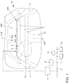
- a motor vehicle K1 shown which is prepared for carrying out the method according to the invention.
- the motor vehicle K1 is visible in the area of a cockpit 1.
- the cockpit 1 comprises an instrument panel 11, on each of which a door panel 2 of front doors adjoins on both sides.
- a center console 12 extends in a conventional manner.
- a steering wheel 10 is also shown.
- LM is a longitudinal center plane of the motor vehicle K1 numbered.
- a lighting device 3 is present in the region of a window root SW of the windshield WS.
- the lens root SW forms the transition relationship or boundary area between the windshield WS and the instrument panel 11.
- the lighting device 3 extends over the entire width or at least almost over the entire width of the windshield WS in a strip-like or line-like manner.
- the illumination device 3 forms a line approximately two to three millimeters high.
- the lighting device 3 consists of a plurality of densely horizontally arranged side by side bulbs, preferably light emitting diodes (not shown in detail).
- the light-emitting diodes are preferably designed as so-called RGB light-emitting diodes, which can emit light in any desired colors.
- the lighting device 3 or its individual lighting means can be controlled via an evaluation and control device 5 such that the lighting means of the lighting device 3 emit light in different colors and / or light phenomena in the form of animations.
- How the lighting device 3 is controlled by the evaluation and control device 5, depends on operating conditions of the motor vehicle K1, for example, the lock state, the driving ready state, etc.
- the evaluation and control device 5 is also active depending on operating conditions of driver assistance systems of the motor vehicle K1.
- the driver assistance systems may include, for example, a navigation system, an AAC system (automatic distance control), a PDC system (parking aid) and / or an infotainment system.
- the evaluation and control device 5 controls the lighting device 3 as a function of environmental variables in the environment of the motor vehicle K1.
- the environment variables can be given for example by collision objects, by the road condition, by the ambient temperature and / or by the ambient brightness.
- the evaluation and control device 5 is connected via a data bus C with an environment detection device 6, with various driver assistance systems 7, with an operating data acquisition system 8 and with a speech recognition system 9 (voice assistant) signal technology.
- Both the environment detection device 6 and the operation data acquisition device 8 have suitable sensors with which the environment or with which operating data can be detected.
- sensors of the operating data acquisition device 8 for example, the driving speed, the engine speed and the fuel supply can be detected.
- the voice recognition system 9 is designed as a kind of voice assistant, and helps the vehicle driver or other vehicle occupants to make operations on the motor vehicle K2 on the basis of voice inputs. These operations may include, for example, audio settings, climate settings, and / or communication settings.
- the lighting device 3 is designed as an approximately horizontally oriented light bar, which allows light phenomena in the form of horizontal, running in directions R1 and / or R2, line-like animations.
- R1 and / or R2 line-like animations.
- the shows Fig. 2 a motor vehicle K2, in which a line or strip-like lighting device 4 in the cockpit 1, on the instrument panel 11 is present.
- the lighting device 4 not only extends over the entire width of the instrument panel 11, but also extends on both sides of the instrument panel 11 along a portion of the door panels 2.
- Licht animationen can be generated, which not only in the directions R1 and R2, but also in directions R3 and R4 are running. In this way, a two-dimensional expression of light animations is thus possible.
- Fig. 3 Based on Fig. 3 is a possible operation of the aforementioned speech recognition system 9 (speech assistant) will be explained.
- the voice input SE1 is "Hello VOLKSWAGEN!.
- the voice assistant then accepts the operating state B1 (Activate).
- This operating state B1 is communicated to the evaluation and control device 5 via the data bus C.
- This in turn means that the evaluation and control device 5, the lighting means of the lighting device 3 controls such that a light appearance appears in the form of an animation A1.
- the voice assistant enters the operating state B2 (output). This leads to the generation of the animation A2, associated with the speech output SA1 ("Yes, please?").
- the voice assistant then switches to operating mode B3 (listening). This is associated with generation of the animation A3.
- the vehicle occupant enters the voice input SE2 ("I am warm!).
- the language assistant then proceeds to the operating states B2 (output) and B4 (confirm), which overlap or are set in parallel. This leads to the generation of the animations A2 and A4, which also overlap or be executed in parallel.
- the animations A2 and A4 are accompanied by the speech output SA2 ("OK!).
- the language assistant then switches to operating mode B5 (processing). This leads to animation A5.
- operating state B5 for example, it is conceivable that the voice assistant causes a climate control device to change the internal temperature accordingly.
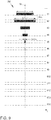
- each animation has (as a rule) only a small amount of time, which is preferably only in the second range.
- the duration of an animation may preferably be between about 1 to 3 seconds.
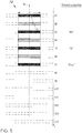
- key representations of the respective performed animation can be captured by the representations.
- each animation is the result of the manner of controlling the adjacently arranged lighting means of the lighting device 3 by the evaluation and control device 5.
- the lighting means (not shown) are preferably designed as light-emitting diodes and arranged next to one another at a mutual distance of approximately 8 to 22 mm.
- a black area means a maximum brightness of a generated light line
- hatched areas means a reduced or dimmed area To represent the brightness of a generated light line.
- An increasing density of the hatching also means an increasing brightness of the generated light line.
- M denotes a center line, to which a line is optionally aligned in the center.
- LL each generated light lines are numbered.
- the width of the animations produced by the language assistant extends only over a partial area of the lighting device 3, preferably the width is only a few centimeters.
- a light line LL having a minimum width bmin is generated.
- the light line LL is continuously expanded to a maximum width bmax (compare t4) and then assumes (time t5) a width b which is slightly smaller than the width bmax. Thereafter, the width b remains constant until the animation A1 is ended.
- the width bmin is already a few millimeters.
- the widths bmax and b are preferably a few centimeters, for example about 10 to 20 centimeters.
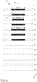
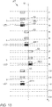
- the Fig. 5 shows the animation A2, which is generated in the operating state B2 (output) of the speech assistant.
- the voice output "is ok!” of the language assistant on the right column of the figure.
- the light-emitting diodes of the lighting device 3 are controlled in such a way that with the output of a syllable by the voice assistant in each case the change to the higher or maximum brightness of the light line LL takes place (compare t3, t5 and t7).
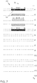
- the Fig. 6 describes the animation A3, which is output in operating state B3 (listening) of the speech assistant.
- a light line LL having a maximum width bmax is generated which is continuously reduced in width to a minimum width bmin (compare time t3).
- the light line LL is increased again up to the maximum width bmax (time t5).
- the process of shrinking and enlarging is repeated cyclically as long as the voice assistant is in the operating state B3.
- the animation A4 is in accordance with Fig. 7 triggered.
- a light line LL with maximum width bmax and maximum brightness is generated.
- the width of the light line LL is continuously reduced to a minimum width bmin and a minimum brightness (time t3).
- the width is increased again up to the maximum width bmax and up to the maximum brightness (time t5).
- animation A4 is shown as a separate animation, it is also conceivable that the animation A4 with the animation A2 (see also Fig. 3 combined.
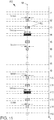
- the animation A5 is shown, which appears when the voice assistant assumes the operating state B5 (processing)).
- the voice assistant therefore causes certain control devices to make desired settings, such as climate or audio settings, by voice input.
- a light line LL with maximum width bmax is generated.
- the width of the light line is reduced to a width b (time t5).
- the light line LL continues to move to the right from the center line M and is reduced in width from a certain time point (t7) until it assumes a minimum width bmin. It reaches with its right end a right end RE (time t8), which originally had the light line LL generated at time t1.
- the minimum width light line LLmin appears with its left end at a position corresponding to a left end LE of the light line LL generated at the time t1.
- the width of the light line LL is increased again up to a width b (compare times t5 and t12) and thereby continuously moves to the right until it is centered to the center line M.
- the width of the Light line LL again continuously until the minimum width reaches bmin and the light line with its right end takes a position corresponding to the right end RE of the light line LL generated at time t1 (see t13).
- the light line LL disappears completely.
- Fig. 9 describes the animation A6, which is generated when processing state B6 (deactivate) the language assistant.
- the center line M can be located at different locations of the lighting device 3.
- the center line M is congruent with a longitudinal center plane FM of the driver side or with a longitudinal center plane BM of the passenger side (see also Fig. 17 ), depending on who comes from a voice input.
- a light line LL is first generated in a width b. Subsequently (time t2), the light line LL is momentarily increased to a maximum width bmax, after which it abruptly decreases to a minimum width bmin (time t5) and completely disappears immediately thereafter (time t6).
- the time interval of the times t1 and t2 is in this case exceptionally much longer than the time intervals between the other mentioned times.
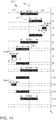
- the Fig. 10 describes an animation A7 that is triggered when the language assistant is in the "wait" mode.
- a light line LL is faded in, with a left end LE1 and a right end RE1 (compare times t1 to t3).
- a new light line with the same width b is displayed, which has a left end LE2 and a right end RE2.
- the left end LE2 coincides with the right end RE1 of the previously displayed light line LL (compare times t4 to t6).
- a new light line LL with the same width b is faded in, with a left end LE3 and a right end RE3.
- the left end LE3 again agrees with the right end RE2 of the previously inserted light line LL (compare times t7 to t9).
- a light line LL with the same width b is faded in, the left end of which coincides with the left end LE1 and the right end with the right end RE1 of the light line initially displayed (times t1 to t3).
- the animation A7 with the times t1 to t9 is repeated until the wait state of the voice assistant is ended.
- the voice assistant waits primarily for a user's voice input.
- an animation A8 is explained in more detail, which is generated in a standby state of the speech assistant by suitable control of the lighting means of the lighting device 3.
- a light line LL with a minimum width bmin is superimposed (time t2), which is increased to a maximum width bmax (time t4).
- the light line LL is again reduced to its minimum width bmin (time t6) and faded out (times t7 to t9).
- the light line LL also assumes its maximum brightness at its maximum width bmax. The process is repeated as long as the voice assistant is in standby mode.
- FIG. 12 An animation A9 is shown in which the voice assistant is in a mode of operation "negate".
- a light line LL is generated which has a width b.
- the light line LL makes jerky rashes to the right and to the left, which is to commemorate a head shake.
- the magnitude of the excursions decreases toward the end of animation A9. This is to be illustrated by way of example with reference to the deflections a1, a2 and a3, which also decrease in size. Finally (time t11), the light line LL rests again in its starting position.
- the animation A10 which in the Fig. 13 is an indication provided by the language assistant.
- a light line LL with a maximum width bmax is generated. This is continuously reduced to a minimum width bmin (compare time t5).
- the brightness of the light line LL changes twice between a minimum and a maximum brightness (compare times t6 to t9) and is then increased again to its maximum width bmax (time t13).
- an animation of the speech assistant is modeled in an animation A11, in which the Language Assistant "happy". This is in Fig. 14 shown.
- a light line with a maximum width bmax is generated, which then makes a rash a to the right with its right end RE.
- the width of the light line LL is reduced to a minimum width bmin (time t3).
- the light line moves back to its original position, wherein the width is increased again to the maximum width bmax (time t5). This is followed by a repetition W of the phases shown in the times t2 to t5.
- the light line LL is moved with its left end LE to the left and performs a rash a, wherein the width of the light line LL is again reduced to a minimum width bmin (time t7).
- the movement to the left is thus carried out analogously to the movement to the right.
- the light line is moved back to its starting position and assumes its maximum width bmax (compare time t9).
- the phases shown at times t6 to t9 are repeated once more (compare times t10 to t13).
- FIG. 15 An animation A12 is also described, which contributes to the "humanization” of the speech assistant.
- the animation A12 should simulate an operating state “Wink” of the language assistant.
- the lighting means of the lighting device 3 are controlled by the evaluation and control device 5 as follows:
- a light line LL having a maximum width bmax is generated. This is continuously reduced from its left end LE to a minimum width bmin (time t5). Subsequently, the brightness of the light line LL is reduced until the light line LL is no longer visible (time t8). Then there is again an insertion of the reduced in width light line LL to the maximum brightness (times t9 to t11) and on the side of the left end LE enlargement to the maximum output width bmax (time t15).
- the main animations are those created by the speech assistant. These give the language assistant a special, personal touch. He can thereby be given a "face”.
- animations will now be described which are generated as a function of the operating state of the motor vehicle K1 and / or as a function of operating states or data of driver assistance systems.
- a light line LL is initially generated, which consists of two outer light lines 14, which are separated by a (dark) distance 13 from each other. Following this, the outer light lines 14 continue to widen apart, wherein at the same time an inner light line 16 is faded in (time t3). Finally, the outer light lines 14 take a maximum distance and also the brightness of the inner light line 16 is so high that the inner light line 16 with the outer light lines 14 optically merges.
- outer light line 14 is faded in (t7). These detach themselves from the inner light line 16 by forming spacings 15 and decreasing in their width until they completely disappear (compare times t7 to t11). With LM again the longitudinal center plane of the motor vehicle K1 is quantified, to which the animation A13 is aligned in the middle.
- Animation A14 is described which may also be used in conjunction with a Welcome scenario. Specifically, the animation A14 should indicate that the service brake of the motor vehicle is to be entered in order to get into the ready-to-drive state.
- the animation A14 first comprises the in Fig. 16 described animation A13, with the difference that the animation A14 is performed generally centrally of a longitudinal center plane FM driver side.
- BM is a longitudinal center plane of the passenger side
- B the width of the interior of the motor vehicle K1 and the width of the lighting device 3 numbered.
- the light line LL Following the animation A13, the light line LL with its maximum width performs deflections to the left, to the right and back to the left before returning to the initial state (compare times t12 to t16). Subsequently, the light line LL is reduced in width until it completely disappears (time t17 to t20).
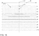
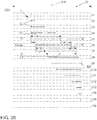
- animation A15 described may also be part of a welcome staging. It should be noted that this animation extends over the entire or almost the entire width B of the interior of the motor vehicle K1. Since in this case also a change in the brightness of the generated light lines LL takes place, this will be illustrated for the sake of simplicity only by showing a dotted line with reduced brightness. Increasing distance of the points means a decreasing brightness.
- a light line LL is initially produced centrally to the longitudinal center plane LM of the motor vehicle. This is then reduced to a minimum width (time t1 to t3). Thereafter, a jerky, significant increase in the width of the light line LL occurs. This is followed by a continuous, rapid broadening of the light line LL, up to a width that corresponds to the width B or almost the width B (time t5 and t6). Subsequently, the light line LL is suppressed until it disappears (times t7 to t10). The period from times t4 to t10 can be accompanied by a signal tone. It is also conceivable to illuminate the light line LL in green color.
- An animation A16 which can be used to support a brake request generated by a driver assistance system.
- the brake request can come, for example, from an automatic distance control system (AAC), a parking aid (PDC) or from a traffic sign recognition system, which would like to alert the driver to an exceeded maximum speed.
- AAC automatic distance control system
- PDC parking aid
- traffic sign recognition system which would like to alert the driver to an exceeded maximum speed.
- the insertion of a light line LL which extends from the beginning over the entire or almost the entire width B of the interior of the motor vehicle K1.
- the light line LL is superimposed to a maximum brightness (compare times t1 to t4), then lights a certain period of time (times t4 to t6) and is then hidden again until disappearing (times t7 to t10).
- the animation A16 can be underpinned in the period from the times t4 to t6, ie during the full brightness of the light line LL, with a signal tone. It is also conceivable that the light line LL is generated in red light.
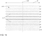
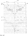
- the Fig. 20 describes an animation A17, which is used in connection with a goodbye scenario.
- a good-bye scenario is conceivable, for example, when the driver sets the speed selector lever to "P" (parking) after stopping the motor vehicle.
- P parking
- first of all a light line LL is generated, which extends over a large part of the width B of the interior, but still has a reduced brightness.
- the brightness of the light line LL is continuously increased up to a maximum brightness, at the same time the width of the light line LL is reduced (compare times t1 to t4).
- the light line LL is additionally separated into an inner light line 16 and two outer light lines 14, which by distances 15 are separated from each other (compare times t5 and t6).
- the width of the inner light line 16 is slightly increased, while the width of the outer light lines 14 is reduced and these disappear.
- the brightness of the inner light line 16 is also reduced until it disappears (compare times t7 to t11). It is conceivable to underlay animation A17 with a beep.
- FIG. 21 An animation A18 is shown, which is intended to inform the vehicle driver that the parking brake of his motor vehicle is actuated.
- the animation A18 is aligned with the longitudinal center plane FM of the driver's side.
- a light line LL is generated and increased to a maximum width.
- external light lines 14 are superimposed, which increasingly separate from the inner light line 16 and disappear (compare times t1 to t4). This is done in a similar manner to the animation A13 already described.
- the light line LL is jerked several times to the right and left, which looks like a wobble and finally comes to rest in its central starting position (compare times t5 to t13).
- the animation 18 may preferably be underlaid with a signal tone in the period of the times t1 to t4. Further, it is conceivable that the inner light line 16 in orange color and the outer light lines 14 are generated in white color.
- the animation A19 shows an animation which is executed when the driver selects the driving mode "D" (driving).
- a central light line 17 is first generated centrally to the longitudinal center axis of the motor vehicle, which is rapidly widened to a maximum width, which extends over a large part of the width B of the interior (see times t1 to t6).
- a central distance 19 which separates the originally generated, central light line 17 into two off-center light lines 18 (compare time t7).
- the distance 19 is then increased continuously.
- the outer lines of light 18 each continue to move outward. This takes place until the off-center light lines 18 have "moved out" of the motor vehicle K1 (compare times t8 to t16).
- animation A20 serves to further inform the driver that he has set the gear selector to R (reverse).
- the animation A20 is basically opposite to the animation A19.
- an off-center light line 18 is generated at the left and at the right outer edge of the illumination device 3, the width of which is continuously increased, so that finally only a smaller distance 19 between the off-center light lines 18 exists (compare times t1 to t6).
- the distance 19 between the off-center light lines 18 is further reduced.
- the width of the light lines 18 is reduced slightly. This takes place until the off-center light lines 18 merge into a central light line 17 (compare time t9).
- the width of the central light line 17 is continuously reduced until it completely disappears (compare times t10 to t15).
- the Fig. 24 again describes an animation A21, which can be used in connection with a Welcome scenario.
- a light line aligned centrally with respect to the longitudinal center plane LM of the motor vehicle is generated, which consists of two outer light lines 14 separated by a visible distance 13.
- the light lines 14 have a reduced brightness.
- the distance 13 of the light lines 14 and also their width are slightly increased.
- an inner light line 16 is faded into the distance 13. This takes place until their brightness coincides with that of the outer light lines 14 and thus the light lines 14 and the light line 16 optically fuse together (time t4). Following this, the resulting light line is split again.
- a standby state of the motor vehicle K1 can be set, for example, when the vehicle driver has opened the vehicle and is waiting for the vehicle driver to actuate the service brake and to set the gear selector lever.
- an animation A22 is generated, which in Fig. 25 is shown.
- a light line LL of narrow width centered on the longitudinal center plane FM of the driver's side is first generated. This is increased to a maximum width, at the same time two outer lines of light 14 low brightness are displayed.
- the originally generated light line LL thus transitions into an inner light line 16 (compare times t1 to t4).
- distances 15 are formed between the outer light lines 14 and the inner light line 16.
- the width of the inner light line 16 is slightly increased (compare time t5).
- the width of the inner light line 16 is reduced again, which leads to an increase in the distances 15.
- the width of the outer light lines 14 is reduced starting from its outer end. This takes place until the outer light lines 14 disappear (compare times t6 and t7).
- the width of the inner light line 16 is again reduced slightly, wherein at the same time again outer light lines 14 are embedded with lower brightness (time t8). There is then again a slight broadening of the inner light line 16, followed by a continuous reduction in the width, so that the inner light line 16 is again separated by distances 15 from the outer light lines 14 (time t10). Further reduction of the width of the inner light line 16 is associated with disappearance of the outer light lines 14 (time t11). Finally, the remaining inner light line 16 is also continuously reduced in width until its disappearance (compare times t12 to t15).
- the partial animation taking place during the time periods t1 to t7 is underlaid with a first tone and the partial animation taking place between the times t8 and t14 is underlaid with a second tone whose frequency is lower than the frequency of the first tone.
- the inner light line 16 in green color and the outer light lines 14 in white color can be generated.
- a short light line LL is generated to the left of the longitudinal center plane LM of the motor vehicle, approximately at the height of the driver, which is continuously increased up to a width b1, in which they already extends over the longitudinal center plane LM (compare times t1 to t5).
- the left end of the light line LL shifts to the right by a length I1.
- the right end of the light line LL shifts to the right by a length I2.
- the length I2 is greater than the length I1.
- the light line LL reaches a maximum width bmax.
- the left end of the light line LL again shifts to the right by the length I2 and the right end of the light line LL by the length I1 to the right. This results in the total width of the light line LL going back to the width b1.
- the light line LL shifts with its width b1 unchanged to the right until the right end of the light line LL reaches an end position EP (compare times t8 and t9). Thereafter, the width of the light line LL is steadily shortened from its left end until the light line LL disappears (see times t10 to t16).
- the animation A23 is preferably repeated three times.
- the animation A23 can, for example, a voice output of the navigation system, preferably the voice output "Turn right now! support.
- an animation can be designed to move to the left, which supports a turn request of the navigation system to the left.
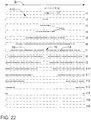
- the Fig. 27 shows an animation A24, which is generated in support of a first-time lane change request of a navigation system.
- a light line LL is generated, which is widened on the side of its right end continuously to the right to a width b1 (compare times t1 to t6).
- the left end of the light line is shifted by a length I1 to the right and the right end by a length I2.
- the length I1 is longer than the length I2.
- an animation 25 is shown, which is to support a second request of the navigation system for a lane change.
- the animation A24 described above first runs with the phases shown there at times t1 to t15. After that, the light line disappears (compare time t16). Thereafter, the animation 24 is repeated again with the phases shown in the times t1 to t15 (compare times t17 to t32). This is followed by a twofold change from a lower brightness to a higher brightness of the remaining light line LL before it finally disappears (compare times t33 to t38).
- an animation A26 is explained, which is intended to support a third lane change request of the navigation system.
- the above-described animation A25 is first performed in the phases described there at times t1 to t32 (compare times t1 to t32). This is followed by a change from a lower brightness of the remaining light line LL to a higher brightness five times until it is finally blanked out (compare times t33 to t44).
- an animation A27 is presented, which is conceivable for visualizing a charging process of a traction battery of the motor vehicle K1, provided that the motor vehicle K1 is designed as a plug-in hybrid or as a pure electric car.
- the light line 20 takes the entire width B of the interior or extends over the entire lighting device 3 (compare time t6). It should be noted that in deviation from the other representations, the time intervals between the successive times t4 and t5 and t5 and t6 are significantly longer than the time intervals between the individual times t1 to t4.
- Animations which serve to visualize a locking state of the motor vehicle. They can also advantageously be used as part of a Leaving Home and Coming Home function.
- a central light line 23 is initially generated centrally to the longitudinal center plane LM of the motor vehicle, which is first slightly widened (times t1 to t3). Subsequently, a central distance 25 is formed, which divides the light line 23 into two eccentric light lines 24 (time t4). Based on this, the distance 25 is further increased. The width of the off-center light lines 24 is also slightly increased (compare times t5 to t8). At a time t9, a further central light line 26 is formed at a distance 25, that is to say between the light lines 24.
- This animation serves to visually indicate to the driver that the motor vehicle has been locked.
- the animation A29 runs symmetrically to the longitudinal center plane LM of the motor vehicle K1.
- 3 off-center lines of light 29 are first generated in the outer edge regions of the lighting device. These lines of light are still very short and are continuously enlarged. In this case, the light lines 29 converge toward one another, so that a distance 30 formed between them also decreases continuously. This continues until the off-center light lines 29 each have reached a maximum width bmax (compare times t1 to t5).
- the width of the off-center light lines 29 and the light lines LL continues to be continuous This is done until the off-center light lines 29 merge into a central light line 31 and at the same time 3 new eccentric light lines 32 arise in the edge regions of the lighting device (compare times t6 to t10). Then the central light line 31 is continuously reduced further until it disappears. At the same time, the off-center light lines 32 converge towards each other, so that a distance 33 between them is reduced. In addition, there is a continuous enlargement of the light lines 32 (compare times t11 and t12). Finally, the off-center light lines 32 continue to converge toward each other, their size continuously decreasing until the off-center lines of light merge into a central line of light 34 and disappear (compare times t13 to t20).
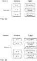
- FIG. 33 Now a possible scenario is explained, which can be realized with the help of already described animations.
- This is a first Welcome scenario Welcome 1, with the corresponding animations in the middle column and the trigger responsible for the respective animation in the right column.
- This is how the animation A21 illustrates (compare Fig. 24 ) a standby state of the motor vehicle, which is modeled on a slow breathing.
- a trigger is conceivable that a door, in particular the driver's door is opened or a certain time (for example, about two seconds) has passed after the door is opened.
- the animation A13 appears (compare Fig. 16 ). This points the driver to another successful step towards vehicle preparation. If the driver subsequently positions the speed selector lever to the D (drive) position, this serves as the trigger for generating the animation A15 (cf. Fig. 18 ).
- the driver receives the direct feedback that his vehicle is now ready to drive.
- FIG. 34 As a modification is a possible second welcome scenario Welcome 2 in Fig. 34 shown.
- the driver selected the driving position D after opening the door, but without having actuated the service brake. This serves as a trigger for generating the animation A14 (cf. Fig. 17 ), which informs the driver that he still has to operate the service brake.
- the animations mentioned in this scenario are followed by the animation A13 when the service brake is applied and the animation A15 when the drive D is engaged.
- a trigger which consists in the brake request of a driver assistance system should be assigned the highest priority.
- An animation triggered by such a trigger must not be interruptible and not delayable.
- an animation triggered by a load may be assigned a lower priority. Such animation may be delayed and / or aborted by a higher priority trigger.
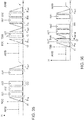
- FIGS. 35 and 36 should be described as an appropriate way of dealing with triggers of different priorities.
- a sequence is shown in which a brightness of an animation is shown on the vertical axis and the time t on the transverse axis.
- AMB the brightness of an ambient lighting is quantified, which is emitted without the occurrence of an animation by the lighting device 3 or by the lighting device 4.
- a lower priority trigger TCC occurs, resulting in a fade in Fin being introduced into an animation CC.
- the animation CC associated with the trigger TCC is played back with partial animations cc1 to ccn by corresponding activation of the lighting means of the lighting device 3 or 4.
- a fade out Fout of the animation CC takes place. Subsequently, the brightness of the ambient lighting AMB is raised again to the normal level.
- the trigger TCC occurs again at a later time t2.
- the superimposition behavior Fin takes place.
- the animation CC begins with its first sub-animation cc1.
- a trigger TBB of medium, ie higher priority occurs during the execution of the first sub-animation cc1.
- the Partial animation cc1 completed and completed with a conventional fade behavior Fout.
- the animation BB is performed with partial animations bb1 and bb2 and then terminated with a fade behavior Fout.
- the ambient lighting AMB is raised again in its brightness H.
- the trigger TBB is a trigger which has a higher priority than the trigger TCC, but which is not time-critical. Therefore, in this case, the current animation is not terminated immediately, but to a reasonable end and completed with a regular blanking behavior.
- a trigger TBB a non-time critical, but higher priority function occurs.
- the associated animation BB is then started with a corresponding overlay behavior Fin. Subsequently, the animation BB starts with part of the first animation bb1.
- a trigger TAA occurs at the time t2, which belongs to an even higher-priority and also time-critical function. Therefore, at the time t2, the current partial animation bb1 is opened immediately, so that there is an aborted partial animation bb1 '.
- an animation AA belonging to the trigger TAA is initiated by generating a generic aperture Foutin (fade out combined with fade in). In order to lose as little time as possible, therefore, the already running animation bb is aborted immediately and thereby masked with a generic, very short fade out.
- the time-critical animation AA starts with the partial animations aa1 to aan.
- the animation AA is completed with a fade out fout.
- the brightness of the ambient lighting AMB is raised again to the normal level.
Abstract
Die Erfindung betrifft ein Verfahren zur Erzeugung eines Lichterscheinungsbildes im Innenraum eines Kraftfahrzeugs (K1, K2), wobei das Lichterscheinungsbild zumindest auch in Abhängigkeit von als Trigger (TAA, TBB, TCC)) wirkenden Betriebszuständen ((B1-B6) des Kraftfahrzeugs (K1, K2) und/oder Umfeldgrößen im Umfeld des Kraftfahrzeugs (K1, K2) erzeugt wird, wobei das Lichterscheinungsbild zumindest im Bereich des Cockpits (1) vom Kraftfahrzeug (K1, K2) in Form einer horizontal ausgerichteten, linienartigen Animation (A1-A29) erzeugt wird, wobei jedem einer Animation zugeordneten Trigger (TAA, TBB, TCC) eine bestimmte Priorität zugewiesen wird, wobei der Eintritt eines Triggers (TBB) mit einer höheren Priorität als ein für eine laufende Animation (CC) ursächlicher Trigger (TCC) zu einem Ende der laufenden Animation (CC) und zu einem Start der dem höher priorisierten Trigger (TBB) zugeordnete Animation (BB) führt, wobei bei Auftreten eines höherpriorisierten, aber zeitunkritischen Triggers (TBB) eine laufende Animation (CC) nur in einer Teilanimation (cc1) durchgeführt wird, wobei die Animation (CC) jedoch mit ihrem üblichen Ausblendverhalten (Fout) beendet wird, bevor die dem höherpriorisierten Trigger (TBB) zugeordnete Animation (BB) gestartet wird, und bei Auftreten eines höher priorisierten und zeitkritischen Triggers (TAA) eine laufende Animation (BB) sofort abgebrochen und der Übergang zu der dem höherpriorisierten Trigger (TAA) zugeordneten Animation (AA) durch eine generische Blende (Foutin) erfolgt, sowie ein Kraftfahrzeug (K1, K2).The invention relates to a method for generating a light appearance in the interior of a motor vehicle (K1, K2), wherein the light appearance at least also in response to acting as a trigger (TAA, TBB, TCC) operating states ((B1-B6) of the motor vehicle (K1, K2) and / or environment variables in the environment of the motor vehicle (K1, K2) is generated, wherein the light appearance at least in the cockpit (1) from the motor vehicle (K1, K2) in the form of a horizontally oriented, line-like animation (A1-A29) generated where each trigger associated with an animation (TAA, TBB, TCC) is assigned a particular priority, with the entry of a trigger (TBB) having a higher priority than a trigger (TCC) causing a current animation (CC) to an end the current animation (CC) and to a start of the higher-priority trigger (TBB) associated animation (BB) leads, wherein when a higher prioritized, but zeitunkriti a current animation (CC) is performed only in a partial animation (cc1), but the animation (CC) is terminated with its usual masking behavior (Fout) before the animation (BBB) associated with the higher prioritized trigger (BBB) ) is started, and when a higher priority and time critical trigger (TAA) occurs, a running animation (BB) is aborted immediately and the transition to the animation (AA) associated with the higher prioritized trigger (TAA) is performed by a generic aperture (Foutin) and a motor vehicle (K1, K2).
Description
Die Erfindung betrifft ein Verfahren zur Erzeugung eines Lichterscheinungsbildes im Innenraum eines Kraftfahrzeugs mit den Merkmalen vom Oberbegriff des Patentanspruchs 1. Die Erfindung betrifft auch ein Kraftfahrzeug zur Durchführung des Verfahrens.The invention relates to a method for generating a light appearance in the interior of a motor vehicle having the features of the preamble of
Ein derartiges Verfahren und ein ebensolches Kraftfahrzeug sind aus der
Aus der
Aus der
Aus der
Ähnliche Vorrichtungen sind aus der
Angesichts dieses Standes der Technik liegt der vorliegenden Erfindung die Aufgabe zu Grunde, ein alternatives Verfahren zur Erzeugung eines Lichterscheinungsbildes im Innenraum eines Kraftfahrzeugs bereitzustellen, welches eine einfache und gut verständliche, visuelle Unterstützung eines Fahrzeuginsassen bereitstellt. Insbesondere soll es den Fahrzeugführer in vielen Fahrsituationen unterstützen, ohne diesen jedoch abzulenken.In view of this prior art, the present invention is based on the object of providing an alternative method for generating a light appearance in the interior of a motor vehicle, which provides a simple and easy-to-understand visual support of a vehicle occupant. In particular, it should support the driver in many driving situations, but without distracting it.
Des Weiteren liegt der Erfindung die Aufgabe zu Grunde, ein geeignetes Kraftfahrzeug zur Durchführung des Verfahrens bereitzustellen. Diese Aufgabe wird mit den Merkmalen von Patentanspruch 19 gelöst.Furthermore, the invention is based on the object to provide a suitable motor vehicle for carrying out the method. This object is achieved with the features of
Vorteilhafte Ausbildungen beziehungsweise Weiterbildungen sind den jeweils abhängigen Ansprüchen entnehmbar.Advantageous embodiments or developments are the respective dependent claims.
Die Erfindung geht aus von einem Verfahren zur Erzeugung eines Lichterscheinungsbildes im Innenraum eines Kraftfahrzeugs. Dabei wird das Lichterscheinungsbild zumindest auch in Abhängigkeit von als Trigger wirkenden Betriebszuständen des Kraftfahrzeugs und/oder Umfeldgrößen im Umfeld des Kraftfahrzeugs erzeugt. Die als Trigger wirkenden Betriebszustände des Kraftfahrzeugs können beispielsweise durch Fahrerassistenzsysteme hervorgerufen sein.The invention is based on a method for generating a light appearance in the interior of a motor vehicle. The light appearance is at least in Dependent on acting as a trigger operating conditions of the motor vehicle and / or environment variables generated in the environment of the motor vehicle. The operating states of the motor vehicle acting as a trigger can be caused, for example, by driver assistance systems.
Der Begriff der Fahrassistenzsysteme soll grundsätzlich solche Systeme umfassen, die der Fahrsicherheit, dem Komfort, der Unterhaltung und/oder der Kommunikation eines Fahrzeuginsassen dienen. Beispielhaft für Fahrassistenzsysteme in diesem Sinne sind eine automatische Distanzregelung (ACC), ein Umfeldbeobachtungssystem (Front Assist), ein Spurhalteassistent (Lane Assist), ein Spurwechselassistent (Side Assist), eine Einparkhilfe (Park Assist), ein Navigationssystem und ein Infotainmentsystem zu nennen.The term of driver assistance systems should basically include such systems that serve the driving safety, comfort, entertainment and / or communication of a vehicle occupant. Exemplary for driver assistance systems in this sense are an automatic distance control (ACC), an environment monitoring system (Front Assist), a lane assist, a lane change assistant (Side Assist), a parking aid (Park Assist), a navigation system and an infotainment system to call.
Umfeldgrößen im Umfeld des Kraftfahrzeugs können beispielsweise durch Verkehrshindernisse, aber auch durch die Beschaffenheit der Fahrbahn (Eis, Schnee, Regen) gebildet sein.Environment variables in the environment of the motor vehicle can be formed for example by traffic obstacles, but also by the nature of the roadway (ice, snow, rain).
Die Erfindung schlägt nun vor, dass das Lichterscheinungsbild zumindest im Bereich des Cockpits vom Kraftfahrzeug in Form einer horizontal ausgerichteten, linienartigen Animation erzeugt wird.The invention now proposes that the light appearance is generated at least in the area of the cockpit by the motor vehicle in the form of a horizontally oriented, line-like animation.
Hierdurch werden optimale Voraussetzungen dafür geschaffen, dass das Lichterscheinungsbild einfach und gut verständlich gestaltet werden kann und darüber hinaus dezent ist. Das Lichterscheinungsbild lenkt den Fahrzeugführer somit nicht ab, sondern unterstützt diesen beim Fahren auf angenehme und zurückhaltende Weise.This creates optimal conditions for the light appearance to be simple and easy to understand, and also discreet. The light appearance thus does not distract the driver, but supports this while driving in a pleasant and restrained manner.
Die Animation kann beispielsweise als Ein-/Ausblendung einer Lichtlinie, deren Bewegung nach rechts/links, durch eine Verbreiterung oder Verkleinerung oder durch ein horizontales Wackeln der Lichtlinie gebildet sein. Bevorzugte Animationen sollen in der Figurenbeschreibung noch detaillierter beschrieben werden.The animation may be formed, for example, as fade in / out of a light line, its movement to the right / left, by a widening or reducing or by a horizontal shaking of the light line. Preferred animations will be described in more detail in the description of the figures.
Dabei ist jedem einer Animation zugeordneten Trigger eine bestimmte Priorität zugewiesen, wobei der Eintritt eines Triggers mit einer höheren Priorität als ein für eine laufende Animation ursächlicher Trigger zu einem Ende der laufenden Animation und zu einem Start der dem höherpriorisierten Trigger zugeordnete Animation führt.Here, each trigger associated with an animation is assigned a particular priority, with the entry of a trigger with a higher priority than a trigger triggering for a running animation leading to an end of the current animation and to a start of the animation associated with the higher prioritized trigger.
Dabei wird bei Auftreten eines höherpriorisierten, aber zeitunkritischen Triggers eine laufende Animation nur in einer Teilanimation durchgeführt, wobei die Animation jedoch mit ihrem üblichen Ausblendverhalten beendet wird, bevor die dem höherpriorisierten Trigger zugeordnete Animation gestartet wird. Hingegen wird bei Auftreten eines höherpriorisierten und zeitkritischen Triggers eine laufende Animation sofort abgebrochen, wobei der Übergang zu der dem höherpriorisierten Trigger zugeordneten Animation durch eine generische Blende erfolgt.In this case, when a higher prioritized, but non-time critical trigger a running animation is performed only in a sub-animation, the animation, however, with their usual blanking behavior is ended before the animation assigned to the higher prioritized trigger is started. On the other hand, when a higher prioritized and time-critical trigger occurs, a running animation is aborted immediately, with the transition to the animation assigned to the higher prioritized trigger being effected by a generic aperture.
In einer höchst vorteilhaften Ausbildung des Erfindungsgedankens erstreckt sich das Lichterscheinungsbild zumindest über einen Großteil der Breite des Cockpits oder wird zumindest über einen Großteil der Breite des Cockpits entlang bewegt. Dies trägt sehr zu einer guten Wahrnehmung und zu einem guten Verständnis für den Fahrzeuginsassen dar. Zudem wird dadurch auch die Flexibilität in den Gestaltungsmöglichkeiten des Lichterscheinungsbildes erhöht.In a most advantageous embodiment of the inventive concept, the light appearance extends at least over a large part of the width of the cockpit or is moved along at least a large part of the width of the cockpit. This contributes greatly to a good perception and a good understanding of the vehicle occupants dar. In addition, thereby the flexibility in the design possibilities of the light appearance is increased.
Sehr zweckmäßig ist es beispielsweise, das Lichterscheinungsbild im Bereich einer Scheibenwurzel der Windschutzscheibe zu erzeugen. Dieser Erzeugungsort gewährleistet, dass der Fahrzeugführer in seinem primären Sichtbereich in keiner Weise beeinträchtigt wird, das Lichterscheinungsbild jedoch wahrgenommen werden kann. Animationen werden dabei quasi auf einer eindimensionalen Fläche abgespielt, wodurch richtungsweisende Informationen durch das Lichterscheinungsbild besonders leicht und verständlich dargestellt werden können.It is very useful, for example, to produce the appearance of light in the region of a lens root of the windshield. This place of production ensures that the driver is in no way impaired in his primary field of vision, but that the appearance of light can be perceived. Animations are played back on a one-dimensional surface, so that trend-setting information can be displayed in a particularly easy and understandable way through the light appearance.
Alternativ ist es denkbar, dass das Lichterscheinungsbild im Bereich einer Instrumententafel und zusätzlich im Bereich einer Türverkleidung beider Vordertüren des Kraftfahrzeugs erzeugt wird. Hierdurch ergibt sich der Vorteil, dass eine zweidimensionale Ausprägung der Animationen möglich ist. So können Animationen von rechts nach links, von links nach rechts und/oder auch zum Fahrer zulaufend oder von diesem weglaufend realisiert werden.Alternatively, it is conceivable that the light appearance is generated in the area of an instrument panel and additionally in the region of a door trim of both front doors of the motor vehicle. This has the advantage that a two-dimensional expression of the animations is possible. Thus animations can be realized from right to left, from left to right and / or also to the driver running away or away from the driver.
Eine andere, sehr zweckmäßige Ausbildung des Erfindungsgedankens schlägt vor, dass das Lichterscheinungsbild als visuelle Begleitung einer fahrzeugseitigen Sprachausgabe und/oder einer Spracheingabe eines Fahrzeuginsassen erzeugt wird. Hierdurch kann ein sogenannter Sprachassistent zur Verfügung gestellt werden, dem der Fahrzeuginsasse Befehle geben und mit dem der Fahrzeuginsasse kommunizieren kann. Dem Sprachassistenten kann somit eine virtuelle "Persönlichkeit" mit eigenem Charakter verliehen werden. Hierdurch fühlt sich die Interaktion mit dem Kraftfahrzeug natürlich und persönlich an. Wie das Lichterscheinungsbild für den Sprachassistenten im Einzelnen vorteilhaft gestaltet werden kann, soll ebenfalls in der Figurenbeschreibung näher erläutert werden. Einer Personalisierung des Sprachassistenten wie zuvor erwähnt, kann dadurch noch intensiviert werden, wenn das Lichterscheinungsbild vor demjenigen Fahrzeuginsassen erzeugt oder nach Erzeugung zu demjenigen Fahrzeuginsassen hinbewegt wird, der die Spracheingabe abgibt oder abgegeben hat.Another, very useful embodiment of the inventive concept proposes that the light appearance is produced as a visual accompaniment to a vehicle-side voice output and / or a voice input by a vehicle occupant. In this way, a so-called voice assistant can be provided, which gives the vehicle occupant commands and with which the vehicle occupant can communicate. The language assistant can thus be given a virtual "personality" with its own character. As a result, the interaction with the motor vehicle feels natural and personal. How the light appearance for the speech assistant in detail can be advantageously designed, will also be explained in more detail in the description of the figures. Personalization of the speech assistant, as mentioned above, can be intensified even further if the light appearance is generated in front of the vehicle occupant or, after being generated, moved toward the vehicle occupant who has given or has given the voice input.
Gleichermaßen ist es einer Personalisierung förderlich, wenn das Lichterscheinungsbild in unterschiedlichen Animationen erzeugt wird oder erzeugbar ist. Jede Animation ist jeweils einem bestimmten Trigger zugeordnet., das heißt, jede Animation wird aufgrund eines bestimmten Triggers gestartet.Likewise, it is conducive to personalization when the light appearance is generated in different animations or is producible. Each animation is assigned to a specific trigger. That is, each animation is started based on a specific trigger.
So kann eine sehr gute Personalisierung dann erzielt werden, wenn der Trigger von einem fahrzeugseitigen Spracherkennungssystem stammt und das Spracherkennungssystem wenigstens Trigger zu Betriebszuständen "aktivieren", "zuhören", "verarbeiten", "ausgeben", "bestätigen", "verneinen", "freuen", "stand by", "hinweisen", "warten", "deaktivieren" und "zuzwinkern" erzeugen kann. Wie dadurch ausgelöste Animationen im Detail aussehen können, wird später in der Figurenbeschreibung näher erläutert.Thus, a very good personalization can be achieved if the trigger originates from a vehicle-side speech recognition system and the speech recognition system at least "activate", "listen", "process", "output", "confirm", "deny", "triggers" to operating states. look forward, stand by, point out, wait, deactivate, and wink. How animations triggered in this way can look in detail will be explained later in the description of the figures.
Eine andere Weiterbildung des Verfahrens schlägt vor, dass das Lichterscheinungsbild zur visuellen Unterstützung einer Welcome- und/oder Goodbye-Funktion des Kraftfahrzeugs erzeugt wird. Auf diese Weise kann eine Inszenierung dieser Funktionen spürbar verbessert werden.Another development of the method proposes that the light appearance is generated for the visual support of a welcome and / or goodbye function of the motor vehicle. In this way, a staging of these functions can be noticeably improved.
Unter einer Welcome-Funktion soll eine solche Funktion verstanden werden, die das Kraftfahrzeug in den fahrbereiten Zustand bringt. Dies kann beispielsweise dadurch geschehen, dass der Fahrzeugführer nach dem Anstellen der Zündung die Bremse tritt und die Fahrstufe "D" (Fahren) einlegt.A welcome function is to be understood as meaning a function which brings the motor vehicle into the ready-to-drive state. This can be done, for example, that the driver after applying the ignition, the brake occurs and the driving position "D" (driving) inserts.
Unter einer Goodbye-Funktion ist eine derartige Funktion zu verstehen, bei der der Fahrzeugführer seine Fahrt beendet hat und das Fahrzeug auf den Stillstand vorbereitet. Dies kann beispielsweise durch Auswahl der Fahrstufe "P" (Parken) erfolgen.A goodbye function is understood to mean a function in which the driver has finished his journey and prepares the vehicle for a standstill. This can be done, for example, by selecting the driving position "P" (parking).
Eine optische Aufwertung einer Coming-Home- und/oder Leaving-Home-Funktion des Kraftfahrzeugs kann dadurch erzielt werden, indem das Lichterscheinungsbild auch zur visuellen Unterstützung einer Coming-Home- und/oder Leaving-Home-Funktion des Kraftfahrzeugs erzeugt wird. Dabei soll unter Coming Home eine solche Funktion verstanden werden, bei der beim Verlassen des Fahrzeugs das Abblendlicht, die Umfeldleuchten in den Außenspiegelgehäusen, das Schlusslicht der Heckleuchten und die Kennzeichenbeleuchtung verzögert ausgeschaltet werden. So kann die Fahrzeugaußenbeleuchtung genutzt werden, um bei Dunkelheit für Fahrzeuginnsassen den Weg zur Haustür beziehungsweise den Weg zum Fahrzeug zu beleuchten.An optical enhancement of a coming home and / or leaving home function of the motor vehicle can be achieved by generating the light appearance also for the visual support of a coming home and / or leaving home function of the motor vehicle. Here Coming Home is to be understood as such a function in which when leaving the vehicle, the low beam, the ambient lights in the exterior mirror housings, the tail light of the tail lights and the License plate light can be switched off with a delay. Thus, the vehicle exterior lighting can be used to illuminate the way to the front door or the way to the vehicle in the dark for vehicle occupants.
Unter Leaving Home ist hingegen eine Funktion zu verstehen, bei der die genannten Beleuchtungsvorrichtungen eingeschaltet werden, wenn der Fahrer mit der Fernbedienung die Verriegelung der Türen öffnet. Dies kann dazu genutzt werden, um bei Dunkelheit den Weg zum Fahrzeug zu beleuchten. Leaving Home , on the other hand, means a function in which the aforementioned lighting devices are switched on when the driver uses the remote control to open the doors. This can be used to illuminate the path to the vehicle in the dark.
In einer anderen Weiterbildung kann das Lichterscheinungsbild zur visuellen Unterstützung einer Bremsaufforderung eines Fahrerassistenzsystems erzeugt werden. Das Fahrerassistenzsystem kann beispielsweise ein Umfeldbeobachtungssystem (Front Assist) sein, welches mittels eines Sensors kritische Abstandssituationen erfasst und den Fahrer bei kritischen Abstandssituationen hilft, den Anhalteweg zu verkürzen. Es ist auch denkbar, dass die Bremsaufforderung von einer Einparkhilfe stammt.In another development, the light appearance can be generated to visually support a brake request of a driver assistance system. The driver assistance system can be, for example, an environment monitoring system (front assist), which detects critical distance situations by means of a sensor and helps the driver in critical distance situations to shorten the stopping distance. It is also conceivable that the brake request comes from a parking aid.
In einer anderen Ausbildung der Erfindung wird vorgeschlagen, dass das Lichterscheinungsbild zur visuellen Unterstützung eines Fahrstufenwechsels, beispielsweise eines automatischen Getriebes erzeugt wird. So ist denkbar, dass eine Animation erzeugt wird, wenn der Fahrstufen-Wählhebel von anderen Stellung in die Fahrstellung (D) oder in die Rückfahrstellung (R) gewechselt wird. Dies erleichtert dem Fahrzeugführer die Orientierung, in welcher Fahrstufe er sich gerade befindet, ohne auf die Anzeige des Wählhebels schauen zu müssen.In another embodiment of the invention, it is proposed that the light appearance is generated to visually assist a speed change, such as an automatic transmission. So it is conceivable that an animation is generated when the speed selector lever is changed from another position to the driving position (D) or in the reverse position (R). This makes it easier for the driver to find out which gear he is currently in, without having to look at the display of the selector lever.
Um die Aussagekraft der Instruktionen eines Navigationssystems zu verstärken, ist es von Vorteil, wenn das Lichterscheinungsbild zur visuellen Unterstützung einer Anweisung eines Navigationssystems erzeugt wird.In order to increase the validity of the instructions of a navigation system, it is advantageous if the light appearance is generated for the visual support of an instruction of a navigation system.
Beispielsweise ist es in einer möglichen Weiterbildung der Erfindung sehr von Vorteil, wenn das Lichterscheinungsbild zur visuellen Unterstützung eine Spurwechselanweisung erzeugt wird. Auf diese Weise kann ein Fahrzeugführer noch intensiver auf einen notwendigen Spurwechsel hingewiesen werden.For example, in one possible development of the invention, it is very advantageous if the light appearance image is generated for visual support by a lane change instruction. In this way, a driver can be made even more aware of a necessary lane change.
Es kann gemäß einer anderen Weiterbildung auch zweckmäßig sein, wenn das Lichterscheinungsbild zur visuellen Unterstützung einer Abbiege-Anweisung erzeugt wird. Auch auf diese Weise kann dann das Verfahren dazu beitragen, dass der Fahrzeugführer rechtzeitig die Notwendigkeit eines Abbiegens erkennt und die gewünschte Route auch wirklich fährt.It may also be useful, according to another embodiment, if the light appearance is generated to visually assist a turn instruction. Also, in this way, the procedure can then help the driver recognize in time the need for a turn and the desired route really drives.
Wenn das Lichterscheinungsbild zur visuellen Unterstützung eines eingehenden Telefonanrufs erzeugt wird, kann das versehentliche Verpassen eines Telefonanrufs vermieden werden.If the light appearance is generated to visually assist an incoming telephone call, accidental missed telephone call can be avoided.
Um einen laufenden Ladevorgang für den Fahrzeugführer und auch für außenstehende Dritte besser sichtbar zu machen, ist es zweckmäßig, wenn das Lichterscheinungsbild zur visuellen Unterstützung eines elektrischen Ladevorgangs einer Traktionsbatterie erzeugt wird.In order to make an ongoing charging process more visible to the driver and also to outside third parties, it is expedient if the light appearance is generated to visually support an electrical charging of a traction battery.
Nach einer anderen Weiterbildung des Verfahrens wird vorgeschlagen, dass das Lichterscheinungsbild zur visuellen Unterstützung einer Warnmeldung für eine Geschwindigkeitsübertretung erzeugt wird. Hierdurch wird eine zusätzliche Möglichkeit geschaffen, dass der Fahrer auf eine Geschwindigkeitsübertretung hingewiesen wird und rechtzeitig diese korrigieren kann.According to another development of the method, it is proposed that the light appearance is generated for visually supporting a warning message for a speeding violation. This creates an additional possibility that the driver is notified of a speeding violation and can correct it in good time.
Wie bereits erwähnt soll mit der Erfindung auch ein Kraftfahrzeug unter Schutz gestellt werden, welches zur Durchführung des Verfahrens geeignet ist.As already mentioned, the invention also provides a motor vehicle under protection, which is suitable for carrying out the method.
Das Kraftfahrzeug weist wenigstens eine Beleuchtungsvorrichtung im Innenraum des Kraftfahrzeugs und wenigstens eine Auswerte- und Steuereinrichtung zur Ansteuerung der Beleuchtungsvorrichtung auf, wobei die Beleuchtungsvorrichtung von der Auswerte- und Steuervorrichtung zumindest in Abhängigkeit von Betriebszuständen ansteuerbar ist. Die Beleuchtungsvorrichtung ist als linienartige Lichtleiste mit einer Vielzahl von nebeneinander angeordneten Leuchtmitteln ausgebildet, wobei die Auswerte- und Steuervorrichtung derart ausgebildet ist, dass jedem einer Animation zugeordneten Trigger eine bestimmte Priorität zugewiesen wird, wobei der Eintritt eines Triggers mit einer höheren Priorität als ein für eine laufende Animation ursächlicher Trigger zu einem Ende der laufenden Animation (CC) und zu einem Start der dem höher priorisierten Trigger zugeordnete Animation führt, wobei bei Auftreten eines höherpriorisierten, aber zeitunkritischen Triggers eine laufende Animation nur in einer Teilanimation durchgeführt wird, wobei die Animation jedoch mit ihrem üblichen Ausblendverhalten beendet wird, bevor die dem höherpriorisierten Trigger zugeordnete Animation gestartet wird, und bei Auftreten eines höher priorisierten und zeitkritischen Triggers eine laufende Animation sofort abgebrochen und der Übergang zu der dem höherpriorisierten Trigger zugeordneten Animation durch eine generische Blende erfolgt.The motor vehicle has at least one lighting device in the interior of the motor vehicle and at least one evaluation and control device for controlling the lighting device, wherein the lighting device of the evaluation and control device is controlled at least in response to operating conditions. The lighting device is formed as a line-like light bar with a plurality of juxtaposed light sources, wherein the evaluation and control device is designed such that each trigger associated with an animation is assigned a certain priority, wherein the entry of a trigger with a higher priority than one for a current animation leads to an end of the current animation (CC) and to a start of the higher prioritized trigger associated animation, wherein when a more prioritized, but non-time critical trigger a running animation is performed only in a sub-animation, the animation with their usual blanking behavior is ended before the animation assigned to the higher prioritized trigger is started, and when a higher priority and time critical trigger occurs, a running animation is aborted immediately and the transition to the higher priority trigger animation associated with a generic iris.
Ein derartiges Kraftfahrzeug weist vorzugsweise eine Umfelderfassungseinrichtung zur Erfassung des Fahrzeugumfeldes. Die Umfelderfassungseinrichtung kann beispielsweise Sensoren umfassen, wie Ultraschall-, Lidar- oder auch Radarsensoren. Auch Kameras sind denkbar.Such a motor vehicle preferably has an environment detection device for detecting the vehicle environment. The environment detection device may include, for example, sensors, such as ultrasound, Lidar- or radar sensors. Also cameras are conceivable.
Ferner weist das Kraftfahrzeug vorzugsweise wenigstens ein Fahrerassistenzsystem auf und ein Spracherkennungssystem zur sprachgeführten Bedienung von Fahrzeugkomponenten. Dabei kann die Beleuchtungsvorrichtung von der Auswerte- und Steuereinrichtung zumindest in Abhängigkeit von Betriebszuständen des Spracherkennungssystems, von Daten der Umfelderfassungseinrichtung und/oder des wenigstens einen Fahrerassistenzsystems ansteuerbar sein oder wird dadurch angesteuert.
Die Lichtleiste erstreckt sich vorzugsweise im Bereich des Cockpits über die gesamte oder nahezu gesamte Breite des Innenraums. Die Leuchtmittel sind vorzugsweise als RGB-Leuchtdioden ausgebildet, welche Licht in beliebigen Farben aussenden können. Der Abstand der Leuchtmittel zueinander kann vorzugsweise in etwa 8 bis 22 mm betragen.Furthermore, the motor vehicle preferably has at least one driver assistance system and a voice recognition system for voice-controlled operation of vehicle components. In this case, the illumination device can be controlled by the evaluation and control device, at least as a function of operating states of the speech recognition system, by data from the surroundings detection device and / or the at least one driver assistance system or is thereby activated.
The light strip preferably extends in the region of the cockpit over the entire or almost entire width of the interior. The light sources are preferably designed as RGB light-emitting diodes, which can emit light in any desired colors. The distance between the lamps to each other may preferably be about 8 to 22 mm.
Zur Realisierung einer eindimensionalen Anzeige ist es ausreichend, wenn die Beleuchtungsvorrichtung in der Scheibenwurzel der Windschutzscheibe angeordnet ist. Dies ist mit einfachen Mitteln und kostengünstig realisierbar. Zudem wird somit das primäre Sichtfeld des Fahrzeugführers nicht beeinträchtigt, aber dennoch eine gute Wahrnehmbarkeit erzielt.For realizing a one-dimensional display, it is sufficient if the lighting device is arranged in the windscreen of the windshield. This can be achieved by simple means and inexpensively. In addition, thus the primary field of vision of the driver is not affected, but still achieved a good visibility.
Alternativ ist auch denkbar, dass die Beleuchtungsvorrichtung im Bereich einer Instrumententafel angeordnet ist und sich zusätzlich beidseitig der Instrumententafel zumindest im Bereich von Türverkleidungen der Vordertüren in Richtung des Fahrzeughecks erstreckt. Auf diese Weise kann eine dreidimensionale Anzeige von Animationen durch das Verfahren realisiert werden, die auf den Fahrzeugführer zuzulaufen oder von ihm wegzulaufen scheint.Alternatively, it is also conceivable that the lighting device is arranged in the region of an instrument panel and in addition extends on both sides of the instrument panel at least in the region of door panels of the front doors in the direction of the vehicle rear. In this way, a three-dimensional display of animations can be realized by the method that seems to be approaching or running away from the driver.
Bevorzugte Ausführungsbeispiele der Erfindung sind in den Figuren dargestellt und werden anhand der Figuren in der nachfolgenden Beschreibung näher erläutert. Dadurch werden auch noch weitere Vorteile der Erfindung deutlich.
Gleiche Bezugszeichen, auch in unterschiedlichen Figuren, beziehen sich auf gleiche, vergleichbare oder funktional gleiche Bauteile. Dabei werden entsprechende oder vergleichbare Eigenschaften und Vorteile erreicht, auch wenn eine wiederholte Beschreibung oder Bezugnahme darauf nicht erfolgt. Die Figuren sind nicht immer maßstabsgetreu. In manchen Figuren können Proportionen übertrieben dargestellt sein, um Merkmale eines Ausführungsbeispiels deutlicher hervorheben zu können.Preferred embodiments of the invention are illustrated in the figures and will be explained in more detail with reference to the figures in the following description. As a result, even further advantages of the invention become apparent.
The same reference numerals, even in different figures, refer to the same, comparable or functionally identical components. In this case, corresponding or comparable properties and advantages are achieved, even if a repeated description or reference does not occur. The figures are not always to scale. In In some figures, proportions may be exaggerated in order to better emphasize features of an embodiment.
Es zeigen, jeweils schematisch
- Fig. 1
- ein zur Durchführung des Verfahrens hergerichtetes Kraftfahrzeug, in einer ersten Ausführungsform,
- Fig. 2
- ein zur Durchführung des Verfahrens hergerichtetes Fahrzeug, in einer zweiten Ausführung,
- Fig. 3
- ein möglicher Verfahrensablauf in Zusammenhang mit Betriebszuständen eines Spracherkennungssystems,
- Fig. 4
bis 15 - durch Ansteuerung von Leuchtmitteln der Beleuchtungsvorrichtung erzielbare Animationen in Zusammenhang mit dem Betriebszustand des Spracherkennungssystems,
- Fig. 16
- eine Animation, getriggert durch den Zustand der Betriebsbremse,
- Fig. 17
und 18 - Animationen, getriggert durch die Position des Fahrstufen-Wählhebels und/oder durch den Betriebszustand der Betriebsbremse,
- Fig. 19
- eine Animation, getriggert durch den Zustand eines ACC-, PDC- oder Front Assist-Systems,
- Fig. 20
- eine Animation, getriggert durch die Position des Fahrstufen-Wählhebels,
- Fig. 21
- eine Animation, getriggert durch den Betriebszustand der Feststellbremse,
- Fig. 22
und 23 - Animationen, getriggert durch die Position des Fahrstufen-Wählhebels,
- Fig. 24
- eine Animation, getriggert durch einen Wartezustand des Kraftfahrzeugs (Stand-By),
- Fig. 25
- eine Animation, getriggert durch den Betriebszustand eines Infotainmentsystems (eingehender Telefonanruf),
- Fig. 26
bis 29 - Animationen, getriggert durch den Betriebszustand eines Navigationssystems,
- Fig. 30
- eine Animation, getriggert durch den Betriebszustand eines Batterieladesystems,
- Fig. 31
und 32 - Animationen, getriggert durch den Verriegelungszustand des Kraftfahrzeugs,
- Fig. 33
und 34 - Tabellen zur Erläuterung unterschiedlicher Welcome-Szenarien des Kraftfahrzeugs und
- Fig. 35 und 36
- die Darstellung der Verfahrensweise bei Eingang von Triggern mit unterschiedlichen Prioritäten.
- Fig. 1
- a motor vehicle prepared for carrying out the method, in a first embodiment,
- Fig. 2
- a vehicle prepared for carrying out the method, in a second embodiment,
- Fig. 3
- a possible procedure in connection with operating states of a speech recognition system,
- Fig. 4 to 15
- animations achievable by driving lighting means of the lighting device in connection with the operating state of the speech recognition system,
- Fig. 16
- an animation, triggered by the state of the service brake,
- FIGS. 17 and 18
- Animations triggered by the position of the speed selector lever and / or by the operating state of the service brake,
- Fig. 19
- an animation triggered by the state of an ACC, PDC or Front Assist system,
- Fig. 20
- an animation triggered by the position of the speed selector lever,
- Fig. 21
- an animation, triggered by the operating state of the parking brake,
- FIGS. 22 and 23
- Animations triggered by the position of the gear selector lever,
- Fig. 24
- an animation, triggered by a waiting state of the motor vehicle (stand-by),
- Fig. 25
- an animation, triggered by the operating state of an infotainment system (incoming telephone call),
- FIGS. 26 to 29
- Animations triggered by the operating state of a navigation system,
- Fig. 30
- an animation, triggered by the operating state of a battery charging system,
- FIGS. 31 and 32
- Animations triggered by the locking state of the motor vehicle,
- FIGS. 33 and 34
- Tables to explain different welcome scenarios of the motor vehicle and
- FIGS. 35 and 36
- the presentation of the procedure when entering triggers with different priorities.
In der
Des Weiteren ist eine Beleuchtungsvorrichtung 3 im Bereich einer Scheibenwurzel SW der Windschutzscheibe WS vorhanden. Die Scheibenwurzel SW bildet den Übergangsbeziehungsweise Grenzbereich zwischen der Windschutzscheibe WS und der Instrumententafel 11.Furthermore, a
Es ist ersichtlich, dass sich die Beleuchtungsvorrichtung 3 streifen- oder linienartig über die gesamte Breite oder zumindest nahezu über die gesamte Breite der Windschutzscheibe WS erstreckt. Vorzugsweise wird durch die Beleuchtungsvorrichtung 3 eine in etwa zwei bis drei Millimeter hohe Linie gebildet.
Konkret besteht die Beleuchtungsvorrichtung 3 aus einer Vielzahl dicht horizontal nebeneinander angeordneter Leuchtmittel, vorzugsweise Leuchtdioden (nicht näher dargestellt). Die Leuchtdioden sind vorzugsweise als sogenannte RGB-Leuchtdioden ausgebildet, welche Licht in beliebigen Farben aussenden können.It can be seen that the
Specifically, the
Die Beleuchtungsvorrichtung 3 beziehungsweise deren einzelne Leuchtmittel sind über eine Auswerte- und Steuereinrichtung 5 derart ansteuerbar, dass die Leuchtmittel der Beleuchtungsvorrichtung 3 Licht in verschiedenen Farben und/oder Lichterscheinungsbilder in Form von Animationen ausstrahlen. Wie die Beleuchtungsvorrichtung 3 durch die Auswerte- und Steuereinrichtung 5 angesteuert wird, hängt von Betriebszuständen des Kraftfahrzeugs K1 ab, beispielsweise vom Verriegelungszustand, vom Fahrbereitschaftszustand, usw. Die Auswerte- und Steuereinrichtung 5 wird auch tätig in Abhängigkeit von Betriebszuständen von Fahrassistenzsystemen des Kraftfahrzeugs K1. Die Fahrerassistenzsysteme können beispielsweise ein Navigationssystem, ein AAC-System (automatische Abstandsregelung), ein PDC-System (Einparkhilfe) und/oder ein Infotainmentsystem umfassen. Ferner steuert die Auswerte- und Steuereinrichtung 5 die Beleuchtungsvorrichtung 3 in Abhängigkeit von Umfeldgrößen im Umfeld des Kraftfahrzeugs K1 an. Die Umfeldgrößen können beispielsweise durch Kollisionsobjekte, durch die Fahrbahnbeschaffenheit, durch die Umgebungstemperatur und/oder durch die Umgebungshelligkeit gegeben sein.The
Daher ist die Auswerte- und Steuereinrichtung 5 über ein Datenbus C mit einer Umfelderfassungseinrichtung 6, mit diversen Fahrerassistenzsystemen 7, mit einem Betriebsdatenerfassungssystem 8 und mit einem Spracherkennungssystem 9 (Sprachassistent) signaltechnisch verbunden. Sowohl die Umfelderfassungseinrichtung 6 als auch die Betriebsdatenerfassungseinrichtung 8 weisen geeignete Sensoren auf, mit denen das Umfeld beziehungsweise mit denen Betriebsdaten erfasst werden können. Durch Sensoren der Betriebsdatenerfassungseinrichtung 8 können beispielsweise die Fahrgeschwindigkeit, die Motordrehzahl und der Kraftstoffvorrat erfasst werden.Therefore, the evaluation and
Das Spracherkennungssystem 9 ist als eine Art Sprachassistent ausgebildet, und hilft dem Fahrzeugführer beziehungsweise anderen Fahrzeuginsassen auf Grund von Spracheingaben Bedienungen diverser Komponenten am Kraftfahrzeug K2 vorzunehmen. Diese Bedienungen können beispielsweise Audioeinstellungen, Klimaeinstellungen und/oder auch Kommunikationseinstellungen betreffen.The
Beim Kraftfahrzeug K1 ist die Beleuchtungsvorrichtung 3 als in etwa horizontal ausgerichtete Lichtleiste ausgebildet, welche Lichterscheinungsbilder in Form von horizontalen, in Richtungen R1 und/oder R2 verlaufenden, linienartigen Animationen erlaubt. Hierbei erfolgt also eine eindimensionale Darstellung.In the motor vehicle K1, the
Im Unterschied dazu zeigt die
Anhand der
Dabei sind in der rechten Spalte Spracheingabe SE1 und SE2 eines Fahrzeuginsassen und in der linken Spalte davon abhängige Betriebszustände B1 bis B6 des Spracherkennungssystems 9 und dadurch verursachte Animationen A1 bis A6 der Beleuchtungsvorrichtung 3 dargestellt.In this case, in the right column voice input SE1 and SE2 of a vehicle occupant and in the left column thereof dependent operating conditions B1 to B6 of the
So lautet im Ausführungsbeispiel die Spracheingabe SE1 "Hallo VOLKSWAGEN!". Daraufhin nimmt der Sprachassistent den Betriebszustand B1 (Aktivieren) an. Dieser Betriebszustand B1 wird der Auswerte- und Steuereinrichtung 5 über den Datenbus C mitgeteilt. Dies führt wiederum dazu, dass die Auswerte- und Steuereinrichtung 5 die Leuchtmittel der Beleuchtungsvorrichtung 3 derart ansteuert, dass ein Lichterscheinungsbild in Form einer Animation A1 erscheint. Analog erfolgt die Vorgehensweise für die weiter genannten Betriebszustände des Sprachassistenten sowie die in Abhängigkeit davon erzeugten Animationen.Thus, in the exemplary embodiment, the voice input SE1 is "Hello VOLKSWAGEN!". The voice assistant then accepts the operating state B1 (Activate). This operating state B1 is communicated to the evaluation and
Vom Betriebszustand B1 geht der Sprachassistent in den Betriebszustand B2 (Ausgeben) über. Dies führt zur Erzeugung der Animation A2, verbunden mit der Sprachausgabe SA1 ("Ja bitte?").From the operating state B1, the voice assistant enters the operating state B2 (output). This leads to the generation of the animation A2, associated with the speech output SA1 ("Yes, please?").
Anschließend geht der Sprachassistent in den Betriebszustand B3 (Zuhören) über. Dies ist mit Erzeugung der Animation A3 verbunden. In diesem Betriebszustand gibt der Fahrzeuginsasse die Spracheingabe SE2 ("Mir ist warm!") ein.The voice assistant then switches to operating mode B3 (listening). This is associated with generation of the animation A3. In this operating state, the vehicle occupant enters the voice input SE2 ("I am warm!").
Der Sprachassistent geht daraufhin in die Betriebszustände B2 (Ausgeben) und B4 (Bestätigen) über, die sich überschneiden beziehungsweise parallel einstellen. Dies führt zur Erzeugung der Animationen A2 und A4, welche sich ebenfalls überschneiden beziehungsweise parallel ausgeführt werden. Die Animationen A2 und A4 werden durch die Sprachausgabe SA2 ("OK!") begleitet.The language assistant then proceeds to the operating states B2 (output) and B4 (confirm), which overlap or are set in parallel. This leads to the generation of the animations A2 and A4, which also overlap or be executed in parallel. The animations A2 and A4 are accompanied by the speech output SA2 ("OK!").
Anschließend geht der Sprachassistent in den Betriebszustand B5 (Verarbeiten) über. Dies führt zur Animation A5. Während des Betriebszustandes B5 ist beispielsweise denkbar, dass der Sprachassistent ein Klimasteuergerät dazu veranlasst, die Innentemperatur entsprechend zu ändern.The language assistant then switches to operating mode B5 (processing). This leads to animation A5. During the operating state B5, for example, it is conceivable that the voice assistant causes a climate control device to change the internal temperature accordingly.
Wurde alles Notwendige veranlasst, so geht der Sprachassistent abermals in den Betriebszustand B2 (Ausgeben) über. Dies führt wiederum zur Animation A2, verbunden mit der Sprachausgabe SA3 ("Gleich wird's kühler!").If everything necessary has been initiated, the language assistant will again switch to operating state B2 (output). This in turn leads to the animation A2, combined with the speech output SA3 ("It's getting cooler!").
Nach erledigter Arbeit nimmt der Sprachassistent den Betriebszustand B6 (Desaktivieren) an. Dies führt zur Animation A6.After completing the work, the language assistant assumes the operating state B6 (Deactivate). This leads to animation A6.
Anhand der
Dabei ist darauf hinzuweisen, dass zur Darstellung des Animationsverlaufs jeweils die durch die Beleuchtungsvorrichtung 3 erzeugten Lichtlinien zu unterschiedlichen, aufeinander folgenden Zeitpunkten dargestellt werden. Die Zeitpunkte werden jeweils in aufsteigender Reihenfolge beziffert, wobei die Zeitabstände zwischen den aufeinanderfolgend dargestellten Zeitpunkten (im Regelfall) in etwa als gleich zu betrachten sind, um eine Vorstellung der ablaufenden Animation zu erhalten. Jede der Animationen weist jedoch (in der Regel) nur eine geringe Zeitdauer auf, die bevorzugt nur im Sekundenbereich liegt. Die Zeitdauer einer Animation kann bevorzugt zwischen etwa 1 bis 3 Sekunden liegen. Insofern können durch die Darstellungen wesentliche Eckpunkte der jeweils durchgeführten Animation erfasst werden. Dabei ist jede Animation das Ergebis der Art und Weise der Ansteuerung der nebeneinander angeordneten Leuchtmittel der Beleuchtungsvorrichtung 3 durch die Auswerte- und Steuereinrichtung 5.
Wie bereits erwähnt sind, die Leuchtmittel (nicht dargestellt) vorzugsweise als Leuchtdioden ausgebildet und in einem gegenseitigen Abstand von etwa 8 bis 22 mm nebeneinander angeordnet.It should be noted that in order to display the animation progression, the light lines generated by the
As already mentioned, the lighting means (not shown) are preferably designed as light-emitting diodes and arranged next to one another at a mutual distance of approximately 8 to 22 mm.
Des Weiteren gilt, dass eine schwarze Fläche eine maximale Helligkeit einer erzeugten Lichtlinie bedeutet, während schraffierte Flächen eine reduzierte beziehungsweise gedimmte Helligkeit einer erzeugten Lichtlinie darstellen sollen. Eine zunehmende Dichte der Schraffur bedeutet gleichfalls auch eine zunehmende Helligkeit der erzeugten Lichtlinie.Furthermore, a black area means a maximum brightness of a generated light line, while hatched areas means a reduced or dimmed area To represent the brightness of a generated light line. An increasing density of the hatching also means an increasing brightness of the generated light line.
Ferner ist in den Figuren mit M eine Mittellinie beziffert, zu der eine Linie gegebenenfalls mittig ausgerichtet ist. Mit LL sind jeweils erzeugte Lichtlinien beziffert. Die Breite der vom Sprachassistenten hervorgerufenen Animationen erstreckt sich jeweils nur über einen Teilbereich der Beleuchtungsvorrichtung 3, vorzugsweise ist die Breite nur einige Zentimeter groß.Furthermore, in the figures, M denotes a center line, to which a line is optionally aligned in the center. With LL each generated light lines are numbered. The width of the animations produced by the language assistant extends only over a partial area of the
So zeigt die
Damit die Lichtlinien LL für einen Fahrzeugführer gut sichtbar sind, reicht es aus, wenn die Breite bmin bereits wenige Millimeter beträgt. Die Breiten bmax und b betragen vorzugsweise einige Zentimeter, beispielsweise in etwa 10 bis 20 Zentimeter.So that the light lines LL are clearly visible to a vehicle driver, it is sufficient if the width bmin is already a few millimeters. The widths bmax and b are preferably a few centimeters, for example about 10 to 20 centimeters.
Die
Dabei wird zunächst eine Lichtlinie LL mit einer bestimmten Breite b und mit einer maximalen Helligkeit erzeugt. In Rhythmus der Sprachausgabe erfolgt dann ein Wechsel der Helligkeit zwischen einer geringeren Helligkeit (vergleiche Zeitpunkte t2, t4 und t6) und einer höheren Helligkeit (vergleiche Zeitpunkte t3, t5 und t7).In this case, first of all a light line LL with a specific width b and with a maximum brightness is generated. In the rhythm of the speech output then takes place a change in brightness between a lower brightness (see times t2, t4 and t6) and a higher brightness (see times t3, t5 and t7).
Im Ausführungsbeispiel werden die Leuchtdioden der Beleuchtungsvorrichtung 3 derart angesteuert, dass mit Ausgabe einer Silbe durch den Sprachassistenten jeweils der Wechsel zur höheren beziehungsweise maximalen Helligkeit der Lichtlinie LL erfolgt (vergleiche t3, t5 und t7).In the exemplary embodiment, the light-emitting diodes of the
Die Animationen A1 und A2 sind zwar als getrennte Animationen dargestellt, es ist jedoch durchaus denkbar, dass diese Animationen überlagert werden.Although the animations A1 and A2 are shown as separate animations, it is quite possible that these animations are superimposed.
Die
Im Betriebszustand B4 (Bestätigen) des Sprachassistenten wird die Animation A4 gemäß
Obwohl die Animation A4 als separate Animation dargestellt ist, ist es auch hierbei denkbar, dass die Animation A4 mit der Animation A2 (vergleiche auch
In der
Schließlich (Zeitpunkt t9) verschwindet die Lichtlinie LL vollends.Finally (time t9) the light line LL disappears completely.
Anschließend (Zeitpunkt t10) erscheint die Lichtlinie LL mit der minimalen Breite bmin mit ihrem linken Ende an einer Position, welche einem linken Ende LE der zum Zeitpunkt t1 erzeugten Lichtlinie LL entspricht. Danach wird die Breite der Lichtlinie LL wieder bis zu einer Breite b (vergleiche Zeitpunkte t5 und t12) vergrößert und wandert dabei kontinuierlich nach rechts, bis sie mittig zur Mittellinie M steht. Nach Erreichen der Breite b nimmt die Breite der Lichtlinie LL wieder kontinuierlich ab, bis wieder die minimale Breite bmin erreicht und die Lichtlinie mit ihrem rechten Ende eine Position einnimmt, die dem rechten Ende RE der zum Zeitpunkt t1 erzeugten Lichtlinie LL entspricht (vergleiche t13). Kurz danach, zum Zeitpunkt t14 verschwindet die Lichtlinie LL vollends.Subsequently (time t10), the minimum width light line LLmin appears with its left end at a position corresponding to a left end LE of the light line LL generated at the time t1. Thereafter, the width of the light line LL is increased again up to a width b (compare times t5 and t12) and thereby continuously moves to the right until it is centered to the center line M. After reaching the width b, the width of the Light line LL again continuously until the minimum width reaches bmin and the light line with its right end takes a position corresponding to the right end RE of the light line LL generated at time t1 (see t13). Shortly thereafter, at time t14, the light line LL disappears completely.
Für die Zeitdauer, in dem sich der Sprachassistent im Bearbeitungszustand B5 (Verarbeiten) befindet, wird die in den Animationsschritten gemäß den Zeitpunkten t10 bis t14 dargestellte Animation kontinuierlich wiederholt.For the period in which the speech assistant is in the processing state B5 (processing), the animation shown in the animation steps according to the times t10 to t14 is continuously repeated.
Es sei darauf hingewiesen, dass sich bei den gezeigten Animationen die Mittellinie M an unterschiedlichen Stellen der Beleuchtungsvorrichtung 3 befinden kann. Vorzugsweise ist die Mittellinie M jedoch deckungsgleich mit einer Längsmittenebene FM der Fahrerseite oder mit einer Längsmittenebene BM der Beifahrerseite (vergleiche auch
Bei der Animation A6 wird nun zunächst eine Lichtlinie LL in einer Breite b erzeugt. Anschließend (Zeitpunkt t2) wird die Lichtlinie LL kurzzeitig bis auf eine maximale Breite bmax vergrößert, um sich danach schlagartig auf eine minimale Breite bmin (Zeitpunkt t5) zu verkleinern und sofort danach (Zeitpunkt t6) ganz zu verschwinden. Der zeitliche Abstand der Zeitpunkte t1 und t2 ist in diesem Fall ausnahmsweise deutlich länger als die zeitlichen Abstände zwischen den anderen genannten Zeitpunkten.In the animation A6, a light line LL is first generated in a width b. Subsequently (time t2), the light line LL is momentarily increased to a maximum width bmax, after which it abruptly decreases to a minimum width bmin (time t5) and completely disappears immediately thereafter (time t6). The time interval of the times t1 and t2 is in this case exceptionally much longer than the time intervals between the other mentioned times.
Die
Dabei stimmt das linke Ende LE2 mit dem rechten Ende RE1 der zuvor eingeblendeten Lichtlinie LL überein (vergleiche Zeitpunkte t4 bis t6). Im Anschluss daran wird wiederum eine neue Lichtlinie LL mit gleicher Breite b eingeblendet, mit einem linken Ende LE3 und einem rechten Ende RE3. Das linke Ende LE3 stimmt wiederum mit dem rechten Ende RE2 der zuvor eingeblendeten Lichtlinie LL überein (vergleiche Zeitpunkte t7 bis t9).The
In this case, the left end LE2 coincides with the right end RE1 of the previously displayed light line LL (compare times t4 to t6). Following this, again a new light line LL with the same width b is faded in, with a left end LE3 and a right end RE3. The left end LE3 again agrees with the right end RE2 of the previously inserted light line LL (compare times t7 to t9).
Im Anschluss daran wird wiederum eine Lichtlinie LL mit der gleichen Breite b eingeblendet, deren linkes Ende mit dem linken Ende LE1 und deren rechtes Ende mit dem rechten Ende RE1 der anfangs (Zeitpunkte t1 bis t3) eingeblendeten Lichtlinie übereinstimmt. Die Animation A7 mit den Zeitpunkten t1 bis t9 wird solange wiederholt, bis der Wartezustand des Sprachassistenten beendet wird. Im Wartezustand wartet der Sprachassistent in erster Linie auf eine Spracheingabe eines Benutzers.Following this, again a light line LL with the same width b is faded in, the left end of which coincides with the left end LE1 and the right end with the right end RE1 of the light line initially displayed (times t1 to t3). The animation A7 with the times t1 to t9 is repeated until the wait state of the voice assistant is ended. When waiting, the voice assistant waits primarily for a user's voice input.
Anhand der
In
Vorzugsweise nimmt die Größe der Ausschläge zum Ende der Animation A9 ab. Dies soll beispielhaft anhand der Ausschläge a1, a2 und a3 dargestellt werden, welche in ihrer Größe ebenfalls abnehmen. Schließlich (Zeitpunkt t11) ruht die Lichtlinie LL wieder in ihrer Ausgangsposition.Preferably, the magnitude of the excursions decreases toward the end of animation A9. This is to be illustrated by way of example with reference to the deflections a1, a2 and a3, which also decrease in size. Finally (time t11), the light line LL rests again in its starting position.
Die Animation A10, welche in der
Anschließend wechselt die Helligkeit der Lichtlinie LL zweimal zwischen einer minimalen und einer maximalen Helligkeit (vergleiche Zeitpunkte t6 bis t9) und wird anschließend wieder zu ihrer maximalen Breite bmax vergrößert (Zeitpunkt t13).The animation A10, which in the
Subsequently, the brightness of the light line LL changes twice between a minimum and a maximum brightness (compare times t6 to t9) and is then increased again to its maximum width bmax (time t13).
Um dem Sprachassistenten eine ganz "persönliche" Note zu geben, wird in einer Animation A11 ein Betriebszustand des Sprachassistenten nachempfunden, bei dem sich der Sprachassistent "freut". Dies ist in
In der
Es wird zunächst eine Lichtlinie LL mit einer maximalen Breite bmax erzeugt. Diese wird ausgehend von ihrem linken Ende LE kontinuierlich bis zu einer minimalem Breite bmin verkleinert (Zeitpunkt t5). Anschließend wird die Helligkeit der Lichtlinie LL soweit reduziert, bis die Lichtlinie LL nicht mehr sichtbar ist (Zeitpunkt t8). Sodann erfolgt wieder eine Einblendung der in der Breite reduzierten Lichtlinie LL bis zur maximalen Helligkeit (Zeitpunkte t9 bis t11) und auf Seite des linken Endes LE eine Vergrößerung bis zur maximalen Ausgangsbreite bmax (Zeitpunkt t15).First, a light line LL having a maximum width bmax is generated. This is continuously reduced from its left end LE to a minimum width bmin (time t5). Subsequently, the brightness of the light line LL is reduced until the light line LL is no longer visible (time t8). Then there is again an insertion of the reduced in width light line LL to the maximum brightness (times t9 to t11) and on the side of the left end LE enlargement to the maximum output width bmax (time t15).
Mit den zuvor beschriebenen Animationen sind die wesentlichen Animationen, welche durch den Sprachassistenten hervorgerufen werden. Diese verleihen dem Sprachassistenten eine besondere, persönliche Note. Ihm kann dadurch ein "Gesicht" gegeben werden.With the animations described above, the main animations are those created by the speech assistant. These give the language assistant a special, personal touch. He can thereby be given a "face".
Die Interaktion mit dem Kraftfahrzeug fühlt sich auf diese Weise natürlich und persönlich an.The interaction with the motor vehicle feels natural and personal in this way.
In den folgenden Figuren sollen nunmehr Animationen beschrieben werden, welche in Abhängigkeit vom Betriebszustand des Kraftfahrzeugs K1 und/oder in Abhängigkeit von Betriebszuständen oder Daten von Fahrerassistenzsystemen erzeugt werden.In the following figures, animations will now be described which are generated as a function of the operating state of the motor vehicle K1 and / or as a function of operating states or data of driver assistance systems.
So ist in
In der
Wie ersichtlich, umfasst die Animation A14 zunächst die in
Im Anschluss an die Animation A13 vollführt die Lichtlinie LL mit ihrer maximalen Breite Auslenkungen nach links, nach rechts und wieder nach links, bevor sie in den Ausgangszustand zurückkehrt (vergleiche Zeitpunkte t12 bis t16). Anschließend wird die Lichtlinie LL in ihrer Breite verringert, bis sie ganz verschwindet (Zeitpunkt t17 bis t20). Die in
In der
Die
Hierbei wird zunächst eine Lichtlinie LL erzeugt, welche über einen Großteil der Breite B des Innenraums reicht, jedoch noch eine reduzierte Helligkeit aufweist. Die Helligkeit der Lichtlinie LL wird kontinuierlich bis zu einer maximalen Helligkeit erhöht, wobei gleichzeitig die Breite der Lichtlinie LL reduziert wird (vergleiche Zeitpunkte t1 bis t4). Im Anschluss daran erfolgt eine weitere Reduzierung der Breite, wobei die Lichtlinie LL zusätzlich in eine innere Lichtlinie 16 und zwei äußere Lichtlinien 14 aufgetrennt wird, welche durch Abstände 15 voneinander getrennt sind (vergleiche Zeitpunkte t5 und t6). Im weiteren Verlauf wird die Breite der inneren Lichtlinie 16 leicht vergrößert, während die Breite der äußeren Lichtlinien 14 verringert wird und diese verschwinden. Gleichzeitig wird auch die Helligkeit der inneren Lichtlinie 16 bis zu ihrem Verschwinden reduziert (vergleiche Zeitpunkte t7 bis t11). Es ist denkbar, die Animation A17 mit einem Signalton zu unterlegen.The
In this case, first of all a light line LL is generated, which extends over a large part of the width B of the interior, but still has a reduced brightness. The brightness of the light line LL is continuously increased up to a maximum brightness, at the same time the width of the light line LL is reduced (compare times t1 to t4). This is followed by a further reduction of the width, wherein the light line LL is additionally separated into an
in der
Anhand der
So zeigt die Animation A19 eine Animation, welche ausgeführt wird, wenn der Fahrzeugführer die Fahrstufe "D" (Fahren) auswählt. Hierbei wird zunächst mittig zur Längsmittenachse des Kraftfahrzeugs eine mittige Lichtlinie 17 erzeugt, welche rasch zu einer maximalen Breite verbreitert wird, welche sich über einen Großteil der Breite B des Innenraums erstreckt (vergleiche Zeitpunkte t1 bis t6). Im Anschluss daran tut sich ein mittiger Abstand 19 auf, der die ursprünglich erzeugte, mittige Lichtlinie 17 in zwei außermittige Lichtlinien 18 trennt (vergleiche Zeitpunkt t7).
Der Abstand 19 wird daraufhin kontinuierlich vergrößert. Danach wandern auch die äußeren Lichtlinien 18 jeweils weiter nach außen. Dies erfolgt solange, bis die außermittigen Lichtlinien 18 aus dem Kraftfahrzeug K1 "herausgewandert" sind (vergleiche Zeitpunkte t8 bis t16).Thus, the animation A19 shows an animation which is executed when the driver selects the driving mode "D" (driving). In this case, a central
The
Im Gegensatz dazu dient eine Animation A20 dazu, dem Fahrzeugführer zusätzlich mitzuteilen, dass er den Fahrstufen-Wählhebel auf R (Rückwärtsfahren) gestellt hat. Die Animation A20 erfolgt im Grunde genommen entgegengesetzt zur Animation A19. So wird zunächst am linken und am rechten äußeren Rand der Beleuchtungsvorrichtung 3 jeweils eine außermittige Lichtlinie 18 erzeugt, deren Breite kontinuierlich vergrößert wird, so dass schließlich nur noch ein kleinerer Abstand 19 zwischen den außermittigen Lichtlinien 18 besteht (vergleiche Zeitpunkte t1 bis t6). Im Anschluss daran wird der Abstand 19 zwischen den außermittigen Lichtlinien 18 weiter verringert. Gleichzeitig wird auch die Breite der Lichtlinien 18 etwas verringert. Dies erfolgt solange, bis die außermittigen Lichtlinien 18 zu einer mittigen Lichtlinie 17 verschmelzen (vergleiche Zeitpunkt t9). Im Anschluss daran wird die Breite der mittigen Lichtlinie 17 kontinuierlich verkleinert, solange bis diese ganz verschwindet (vergleiche Zeitpunkte t10 bis t15).In contrast, animation A20 serves to further inform the driver that he has set the gear selector to R (reverse). The animation A20 is basically opposite to the animation A19. Thus, first an off-
Die
Die Animation A21 wird mit den in den Zeitpunkten t1 bis t15 gezeigten Schritten solange wiederholt, bis der Standby-Zustand endet. Ein Standby-Zustand des Kraftfahrzeugs K1 kann sich beispielsweise dann einstellen, wenn der Fahrzeugführer das Fahrzeug geöffnet hat und darauf gewartet wird, dass der Fahrzeugführer die Betriebsbremse betätigt und den Fahrstufen-Wählhebel einstellt.The
The animation A21 is repeated with the steps shown at times t1 to t15 until the standby state ends. A standby state of the motor vehicle K1 can be set, for example, when the vehicle driver has opened the vehicle and is waiting for the vehicle driver to actuate the service brake and to set the gear selector lever.
Wird von einem Infotainmentsystem ein ankommender Anruf festgestellt, so wird eine Animation A22 erzeugt, welche in
Anschließend wird die Breite der inneren Lichtlinie 16 abermals etwas verringert, wobei gleichzeitig wiederum äußere Lichtlinien 14 mit geringerer Helligkeit eingebettet werden (Zeitpunkt t8). Es erfolgt danach noch einmal eine geringfügige Verbreiterung der inneren Lichtlinie 16, gefolgt von einer kontinuierlichen Verringerung der Breite, so dass die innere Lichtlinie 16 wieder durch Abstände 15 von den äußeren Lichtlinien 14 getrennt wird (Zeitpunkt t10). Eine weitere Verringerung der Breite der inneren Lichtlinie 16 wird mit einem Verschwinden der äußeren Lichtlinien 14 verbunden (Zeitpunkt t11). Schließlich wird die übrig gebliebene, innere Lichtlinie 16 ebenfalls kontinuierlich bis zu ihrem Verschwinden in ihrer Breite verringert (vergleiche Zeitpunkte t12 bis t15). Dabei ist denkbar, dass die im Zeitraum der Zeitpunkte t1 bis t7 ablaufende Teilanimation mit einem ersten Ton und die zwischen den Zeitpunkten t8 und t14 ablaufende Teilanimation mit einem zweiten Ton unterlegt wird, dessen Frequenz niedriger ist als die Frequenz des ersten Tons. Des Weiteren können bspw. die innere Lichtlinie 16 in grüner Farbe und die äußeren Lichtlinien 14 in weißer Farbe erzeugt werden.Subsequently, the width of the
Anhand der nachfolgenden
So zeigt die
Dies führt optisch dazu, dass sich die Lichtlinie LL raupenartig von links nach rechts zu bewegen scheint. Die Animation A23 wird vorzugsweise dreimal wiederholt. Die Animation A23 kann beispielsweise eine Sprachausgabe des Navigationssystems, bevorzugt die Sprachausgabe "Jetzt rechts abbiegen!" unterstützen. Analog kann eine Animation nach links bewegend ausgestaltet sein, die eine Abbiegeaufforderung des Navigationssystems nach links unterstützt.This leads visually to the fact that the light line LL seems to move caterpillar-like from left to right. The animation A23 is preferably repeated three times. The animation A23 can, for example, a voice output of the navigation system, preferably the voice output "Turn right now!" support. Analogously, an animation can be designed to move to the left, which supports a turn request of the navigation system to the left.
Die
Dies führt zu einer geringfügigen Verringerung der Breite der Lichtlinie LL zu einer Breite b2 (vergleiche Zeitpunkt t7). Im Anschluss daran verschiebt sich die Lichtlinie LL in ihrer Gesamtheit und in ihrer Breite im Wesentlichen gleichbleibend solange nach rechts, bis ihr rechtes Ende einen Endpunkt EP erreicht (vergleiche Zeitpunkte t8 bis t10). Danach wird das linke Ende der Lichtlinie LL stetig nach rechts verschoben, bis die Lichtlinie LL eine kleinste Breite bmin aufweist (vergleiche Zeitpunkte t11 bis t15). Schließlich wird die Lichtlinie LL noch einmal kontinuierlich dunkler und wieder heller, bis sie danach ganz verschwindet (vergleiche Zeitpunkte t16 bis t19).This leads to a slight reduction in the width of the light line LL to a width b2 (compare time t7). Following this, the light line LL in its entirety and in its width substantially uniformly shifts to the right until its right end reaches an end point EP (compare times t8 to t10). Thereafter, the left end of the light line LL is steadily shifted to the right until the light line LL has a smallest width bmin (see times t11 to t15). Finally, the light line LL becomes continuously darker and brighter again until it disappears completely afterwards (compare times t16 to t19).
In der
In der
Durch die erzeugten Animationen A24 bis A26 wird dem Fahrzeugführer also eine steigende Dringlichkeit des notwendigen Spurwechsels visualisiert.The generated animations A24 to A26 so the driver is an increasing urgency of the necessary lane change visualized.
In der
Es ist ersichtlich, dass mit Beginn des Ladevorgangs (Zeitpunkt t1) eine sich über die gesamte Breite B oder nahezu die gesamte Breite B des Innenraums erstreckendes Lichterscheinungsbild erzeugt wird. Dieses weist zunächst eine zur Längsmittenebene LM des Kraftfahrzeugs mittige Lichtlinie 20 auf. Beidseitig der Lichtlinie 20 sind deutlich kleinere, außermittige Lichtlinien 21 vorhanden, welche sich langsam nach innen, also in Richtung auf die mittige Lichtlinie 20 bewegen (vergleiche Pfeile). Dies führt dazu, dass in regelmäßigen Abständen beidseitig der mittigen Lichtlinie 20 jeweils eine außermittige Lichtlinie 21 mit der mittigen Lichtlinie 20 zu verschmelzen scheint (vergleiche Zeitpunkt t4). Mit steigender Ladezeit verbreitert sich die mittige Lichtlinie 20, um den steigenden Ladestatus zu verdeutlichen (vergleiche Zeitpunkt t5). In voll aufgeladenem Zustand nimmt die Lichtlinie 20 die gesamte Breite B des Innenraums ein beziehungsweise erstreckt sich über die gesamte Beleuchtungsvorrichtung 3 (vergleiche Zeitpunkt t6). Hierbei ist darauf hinzuweisen, dass in Abweichung von den sonstigen Darstellungen die zeitlichen Abstände zwischen den aufeinander folgenden Zeitpunkten t4 und t5 sowie t5 und t6 wesentlich länger sind als die zeitlichen Abstände zwischen den einzelnen Zeitpunkten t1 bis t4.It can be seen that with the beginning of the charging process (time t1), a light appearance extending over the entire width B or almost the entire width B of the interior is generated. This first has a longitudinal center plane LM of the motor vehicle central
Anhand der
So ist in
In der
Als Abwandlung ist ein mögliches zweites Welcome-Szenario Welcome 2 in
Bei der Vielzahl der möglichen Trigger für die Erzeugung von Animationen ist es notwendig, die einzelnen Funktionen bzw. Trigger zu priorisieren. Es ist zweckmäßig, ein Verfahren festzulegen, wie beim Auftreten von mehreren Triggern, was theoretisch zu einer notwendigen Überlagerung von ausgelösten Animationen führen würde, verfahren werden soll. Insbesondere gibt es zeitunkritische und zeitkritische Trigger. Ebenso können den den Animationen zu Grunde liegenden Triggern unterschiedliche Prioritäten zugewiesen werden.Given the large number of possible triggers for generating animations, it is necessary to prioritize the individual functions or triggers. It is convenient, a procedure determine how to proceed when multiple triggers occur, which would theoretically lead to a necessary overlay of triggered animations. In particular, there are time-critical and time-critical triggers. Similarly, the animations underlying the triggers can be assigned different priorities.
Grundsätzlich ist es zweckmäßig, einem zeitkritischen Trigger auch eine hohe Priorität, wenn nicht sogar die höchste Priorität zuzurechnen.In principle, it is expedient to assign a high priority, if not the highest priority, to a time-critical trigger.
So sollte beispielsweise einem Trigger, welcher in der Bremsaufforderung eines Fahrerassistenzsystems besteht, die höchste Priorität zugeordnet werden. Eine durch einen solchen Trigger ausgelöste Animation darf nicht unterbrechbar und auch nicht verzögerbar sein. Währenddessen kann einer Animation, welche durch einen Ladevorgang getriggert wird, eine niedrigere Priorität zugeordnet werden. Eine solche Animation kann verzögert und/oder durch einen Trigger höherer Priorität abgebrochen werden.For example, a trigger which consists in the brake request of a driver assistance system should be assigned the highest priority. An animation triggered by such a trigger must not be interruptible and not delayable. Meanwhile, an animation triggered by a load may be assigned a lower priority. Such animation may be delayed and / or aborted by a higher priority trigger.
Anhand der
So ist in der
Zum Zeitpunkt t1 tritt ein Trigger TCC mit niedrigere Priorität auf, was dazu führt, dass ein Einblendverhalten (Fade in) Fin in eine Animation CC eingeleitet wird.
Danach wird die zum Trigger TCC zugehörige Animation CC mit Teilanimationen cc1 bis ccn durch entsprechende Ansteuerung der Leuchtmittel der Beleuchtungsvorrichtung 3 beziehungsweise 4 abgespielt. Am Ende der Animation CC findet ein Ausblendverhalten (Fade out) Fout der Animation CC statt. Anschließend wird die Helligkeit der Ambientebeleuchtung AMB wieder auf das normale Maß angehoben.At time t1, a lower priority trigger TCC occurs, resulting in a fade in Fin being introduced into an animation CC.
Thereafter, the animation CC associated with the trigger TCC is played back with partial animations cc1 to ccn by corresponding activation of the lighting means of the
Weiter ist beispielhaft dargestellt, dass zu einem späteren Zeitpunkt t2 abermals der Trigger TCC auftritt. Hierbei findet zunächst wieder das Einblendverhalten Fin statt. Danach beginnt die Animation CC mit ihrer ersten Teilanimation cc1. Allerdings tritt während der Ausführung der ersten Teilanimation cc1 ein Trigger TBB einer mittleren, also höheren Priorität auf. Dies führt dazu, dass die Animation CC vorzeitig beendet wird. Allerdings wird noch die Teilanimation cc1 zu Ende geführt und mit einem üblichen Ausblendverhalten Fout abgeschlossen. Erst danach wird das Einblendverhalten Fin einer dem Trigger TBB zugeordneten Animation BB gestartet. Die Animation BB wird mit Teilanimationen bb1 und bb2 durchgeführt und anschließend mit einem Ausblendverhalten Fout beendet.
Anschließend wird die Ambientebeleuchtung AMB in ihrer Helligkeit H wieder angehoben. Bei dem Trigger TBB handelt es sich um einen Trigger, welcher zwar eine höhere Priorität als der Trigger TCC aufweist, der jedoch nicht zeitkritisch ist. Daher wird in diesem Fall die laufende Animation nicht sofort, sondern zu einem sinnvollen Ende beendet und mit einem regulieren Ausblendverhalten abgeschlossen.Furthermore, it is shown by way of example that the trigger TCC occurs again at a later time t2. Here again, the superimposition behavior Fin takes place. Thereafter, the animation CC begins with its first sub-animation cc1. However, during the execution of the first sub-animation cc1, a trigger TBB of medium, ie higher priority occurs. This will cause the animation CC to end prematurely. However, the Partial animation cc1 completed and completed with a conventional fade behavior Fout. Only then is the overlay behavior Fin of an animation BB associated with the trigger TBB started. The animation BB is performed with partial animations bb1 and bb2 and then terminated with a fade behavior Fout.
Subsequently, the ambient lighting AMB is raised again in its brightness H. The trigger TBB is a trigger which has a higher priority than the trigger TCC, but which is not time-critical. Therefore, in this case, the current animation is not terminated immediately, but to a reasonable end and completed with a regular blanking behavior.
In
Im Anschluss daran startet die zeitkritische Animation AA mit den Teilanimationen aa1 bis aan. Die Animation AA wird mit einem Fade out Fout wieder abgeschlossen. Anschließend wird die Helligkeit der Ambientebeleuchtung AMB wieder auf das Normalmaß angehoben.Subsequently, the time-critical animation AA starts with the partial animations aa1 to aan. The animation AA is completed with a fade out fout. Subsequently, the brightness of the ambient lighting AMB is raised again to the normal level.
- 11
- Cockpitcockpit
- 22
- Türverkleidungdoor trim
- 33
- Beleuchtungsvorrichtunglighting device
- 44
- Beleuchtungsvorrichtunglighting device
- 55
- Auswerte- und SteuereinrichtungEvaluation and control device
- 66
- UmfelderfassungseinrichtungSurroundings sensing device
- 77
- FahrerassistenzsystemeDriver assistance systems
- 88th
- BetriebsdatenerfassungseinrichtungOperating data acquisition device
- 99
- Spracherkennungssystem, SprachassistentSpeech recognition system, speech assistant
- 1010
- Lenkradsteering wheel
- 1111
- Instrumententafeldashboard
- 1212
- Mittelkonsolecenter console
- 1313
- Abstanddistance
- 1414
- äußere Lichtlinienouter light lines
- 1515
- Abständedistances
- 1616
- innere Lichtlinieinner light line
- 1717
- mittige Lichtliniecentral light line
- 1818
- außermittige Lichtlinienoff-center light lines
- 1919
- Abstanddistance
- 2020
- mittige Lichtliniecentral light line
- 2121
- außermittige Lichtlinienoff-center light lines
- 2222
- Abständedistances
- 2323
- mittige Lichtliniecentral light line
- 2424
- außermittige Lichtlinienoff-center light lines
- 2525
- Abstanddistance
- 2626
- mittige Lichtliniecentral light line
- 2727
- außermittige Lichtlinienoff-center light lines
- 2828
- Abstanddistance
- 2929
- außermittige Lichtlinienoff-center light lines
- 3030
- Abstanddistance
- 3131
- mittige Lichtliniecentral light line
- 3232
- außermittige Lichtlinienoff-center light lines
- 3333
- Abstanddistance
- 3434
- mittige Lichtliniecentral light line
- aa
- Ausschlagrash
- a1-a3a1-a3
- Ausschlagrash
- aa1-aanaa1-aan
- Teilanimationenpart animations
- A1-A12A1-A12
- Animationen, getriggert durch den Zustand des SpracherkennungssystemsAnimations triggered by the state of the speech recognition system
- A13, A14A13, A14
- Animationen, getriggert durch den Zustand der BetriebsbremseAnimations triggered by the state of the service brake
- A16A16
- Animation, getriggert durch den Zustand eines ACC-, PDC- oder Frontassist-Systems (Bremsaufforderung)Animation, triggered by the state of an ACC, PDC or Frontassist system (brake request)
- A15, A17, A19, A20A15, A17, A19, A20
- Animationen, getriggert durch den Zustand des Fahrstufen-WählhebelsAnimations triggered by the state of the gear selector lever
- A18A18
- Animation, getriggert durch den Zustand der FeststellbremseAnimation triggered by the condition of the parking brake
- A21A21
- Animation (Stand By)Animation (Stand By)
- A22A22
- Animation (eingehender Telefonanruf)Animation (incoming phone call)
- A23-A26A23-A26
- Animationen, getriggert durch den Zustand des NavigationssystemsAnimations triggered by the state of the navigation system
- A27A27
- Animation (Batterie wird geladen)Animation (battery is charging)
- A28A28
- Animation (Fahrzeug wird entriegelt)Animation (vehicle is unlocked)
- A29A29
- Animation (Fahrzeug wird verriegelt)Animation (vehicle is locked)
- AAAA
- Animation mit der höchsten Priorität AAnimation with the highest priority A
- AMBAMB
- AmbientebeleuchtungAmbient lighting
- bb
- Breitewidth
- bb1, bb2bb1, bb2
- Teilanimationenpart animations
- bb1'flat1 '
- abgebrochene Teilanimationaborted partial animation
- b1, b2b1, b2
- Breitewidth
- bmaxbmax
- maximale Breitemaximum width
- bminb min
- minimale Breiteminimum width
- BB
- Breite des InnenraumsWidth of the interior
- BBBB
- Animation mit einer mittleren Priorität BAnimation with a medium priority B
- BMBM
- Längsmittenebene der BeifahrerseiteLongitudinal center plane of the passenger side
- B1-B6B1-B6
- Betriebszustände des SpracherkennungssystemsOperating states of the speech recognition system
- cc1-ccncc1-ccn
- Teilanimationenpart animations
- CC
- Datenbus (CAN)Data bus (CAN)
- CCCC
- Animation mit der niedrigsten Priorität CCAnimation with the lowest priority CC
- EPEP
- Endpositionend position
- FinFin
- Einblendverhalten einer Animation (Fade in)Pop-up behavior of an animation (fade in)
- FMFM
- Längsmittenebene der FahrerseiteLongitudinal center plane of the driver's side
- FoutFout
- Ausblendverhalten einer Animation (Fade out)Fade out behavior of an animation (fade out)
- FoutinFoutin
- generische Blende (Fade out mit Fade in kombiniert)generic aperture (fade out combined with fade in)
- HH
- Helligkeitbrightness
- K1, K2K1, K2
- Kraftfahrzeugmotor vehicle
- I1, I2I1, I2
- Längelength
- LELE
- linkes Endeleft end
- LE1-LE3LE1-LE3
- linkes Endeleft end
- LLLL
- Lichtlinienlight lines
- LMLM
- Längsmittenebene vom KraftfahrzeugLongitudinal center plane of the motor vehicle
- MM
- Mittelliniecenter line
- R1-R4R1-R4
- Richtungendirections
- RERE
- rechtes Enderight end
- RE1-RE3RE1-RE3
- rechtes Enderight end
- SA1-SA3SA1-SA3
- Sprachausgaben des SpracherkennungssystemsSpeech outputs of the speech recognition system
- SE1, SE2SE1, SE2
- Spracheingabenvoice commands
- SWSW
- Scheibenwurzeldisk root
- tt
- ZeitTime
- t1-t14t1-t14
- Zeitpunktetimings
- TAATAA
- Trigger für die Animation AATrigger for the animation AA
- TBBTBB
- Trigger für die Animation BBTrigger for the animation BB
- TCCTCC
- Trigger für die Animation CCTrigger for the animation CC
- WW
- Wiederholung der AnimationRepeat the animation
- WSWS
- WindschutzscheibeWindshield
Claims (21)
dadurch gekennzeichnet, dass
jedem einer Animation zugeordneten Trigger (TAA, TBB, TCC) eine bestimmte Priorität zugewiesen wird, wobei der Eintritt eines Triggers (TBB) mit einer höheren Priorität als ein für eine laufende Animation (CC) ursächlicher Trigger (TCC) zu einem Ende der laufenden Animation (CC) und zu einem Start der dem höher priorisierten Trigger (TBB) zugeordnete Animation (BB) führt, wobei
bei Auftreten eines höherpriorisierten, aber zeitunkritischen Triggers (TBB) eine laufende Animation (CC) nur in einer Teilanimation (cc1) durchgeführt wird, wobei die Animation (CC) jedoch mit ihrem üblichen Ausblendverhalten (Fout) beendet wird, bevor die dem höherpriorisierten Trigger (TBB) zugeordnete Animation (BB) gestartet wird, und
bei Auftreten eines höher priorisierten und zeitkritischen Triggers (TAA) eine laufende Animation (BB) sofort abgebrochen und der Übergang zu der dem höherpriorisierten Trigger (TAA) zugeordneten Animation (AA) durch eine generische Blende (Foutin) erfolgt.Method for generating a light appearance in the interior of a motor vehicle (K1, K2), wherein the light appearance at least depending on acting as a trigger (TAA, TBB, TCC) operating states ((B1-B6) of the motor vehicle (K1, K2) and / or environment variables in the environment of the motor vehicle (K1, K2) is generated, wherein the light appearance is generated at least in the area of the cockpit (1) by the motor vehicle (K1, K2) in the form of a horizontally oriented, line-like animation (A1-A29),
characterized in that
each trigger associated with an animation (TAA, TBB, TCC) is assigned a particular priority, wherein the entry of a trigger (TBB) with a higher priority than a current animation (CC) causal trigger (TCC) to an end of the current animation (CC) and leads to a start of the higher-priority trigger (TBB) associated animation (BB), wherein
when a higher prioritized, but time-critical trigger (TBB) occurs, a running animation (CC) is performed only in a partial animation (cc1), but the animation (CC) is terminated with its usual fade-out behavior (Fout) before the higher-priority trigger (C) TBB) associated animation (BB) is started, and
when a higher-priority and time-critical trigger (TAA) occurs, a running animation (BB) is aborted immediately and the transition to the animation (AA) assigned to the higher prioritized trigger (TAA) is effected by a generic aperture (Foutin).
bei Auftreten eines höherpriorisierten, aber zeitunkritischen Triggers (TBB) eine laufende Animation (CC) nur in einer Teilanimation (cc1) durchgeführt wird, wobei die Animation (CC) jedoch mit ihrem üblichen Ausblendverhalten (Fout) beendet wird, bevor die dem höherpriorisierten Trigger (TBB) zugeordnete Animation (BB) gestartet wird, und
bei Auftreten eines höher priorisierten und zeitkritischen Triggers (TAA) eine laufende Animation (BB) sofort abgebrochen und der Übergang zu der dem höherpriorisierten Trigger (TAA) zugeordneten Animation (AA) durch eine generische Blende (Foutin) erfolgt.Motor vehicle (K1, K2) for carrying out the method according to one of the preceding claims, with at least one lighting device (3, 4) in the interior of the motor vehicle (K1, K2) and with at least one evaluation and control device (5) for driving the lighting device ( 3, 4), wherein the lighting device (3, 4) of the evaluation and control device (5) at least in response to operating conditions (B1-B6) is controllable, and the lighting device (3, 4) as a line-like light bar with a plurality of is formed adjacently arranged lighting means, wherein the evaluation and control device (5) is designed such that each of an animation assigned trigger (TAA, TBB, TCC) is assigned a certain priority, wherein the entry of a trigger (TBB) with a higher priority than a current animation (CC) causal trigger (TCC) to an end of the current animation (CC) and results in a start of the higher priority trigger (TBB) associated animation (BB), where
when a higher prioritized, but time-critical trigger (TBB) occurs, a running animation (CC) is performed only in a partial animation (cc1), but the animation (CC) is terminated with its usual fade-out behavior (Fout) before the higher-priority trigger (C) TBB) associated animation (BB) is started, and
when a higher-priority and time-critical trigger (TAA) occurs, a running animation (BB) is aborted immediately and the transition to the animation (AA) assigned to the higher prioritized trigger (TAA) is effected by a generic aperture (Foutin).
Applications Claiming Priority (4)
| Application Number | Priority Date | Filing Date | Title |
|---|---|---|---|
| DE102017003510 | 2017-04-11 | ||
| DE102017003511 | 2017-04-11 | ||
| DE102017222174.7A DE102017222174A1 (en) | 2017-04-11 | 2017-12-07 | Lighting device for an interior of a motor vehicle |
| EP18152960.3A EP3388286B1 (en) | 2017-04-11 | 2018-01-23 | Method for generating a light appearance image in the interior of a motor vehicle and motor vehicle for carrying out the method |
Related Parent Applications (2)
| Application Number | Title | Priority Date | Filing Date |
|---|---|---|---|
| EP18152960.3A Division EP3388286B1 (en) | 2017-04-11 | 2018-01-23 | Method for generating a light appearance image in the interior of a motor vehicle and motor vehicle for carrying out the method |
| EP18152960.3A Division-Into EP3388286B1 (en) | 2017-04-11 | 2018-01-23 | Method for generating a light appearance image in the interior of a motor vehicle and motor vehicle for carrying out the method |
Publications (2)
| Publication Number | Publication Date |
|---|---|
| EP3556610A1 true EP3556610A1 (en) | 2019-10-23 |
| EP3556610B1 EP3556610B1 (en) | 2022-11-16 |
Family
ID=61024595
Family Applications (2)
| Application Number | Title | Priority Date | Filing Date |
|---|---|---|---|
| EP18152960.3A Active EP3388286B1 (en) | 2017-04-11 | 2018-01-23 | Method for generating a light appearance image in the interior of a motor vehicle and motor vehicle for carrying out the method |
| EP19168249.1A Active EP3556610B1 (en) | 2017-04-11 | 2018-01-23 | Method for generating a light appearance image in the interior of a motor vehicle and motor vehicle for carrying out the method |
Family Applications Before (1)
| Application Number | Title | Priority Date | Filing Date |
|---|---|---|---|
| EP18152960.3A Active EP3388286B1 (en) | 2017-04-11 | 2018-01-23 | Method for generating a light appearance image in the interior of a motor vehicle and motor vehicle for carrying out the method |
Country Status (1)
| Country | Link |
|---|---|
| EP (2) | EP3388286B1 (en) |
Families Citing this family (3)
| Publication number | Priority date | Publication date | Assignee | Title |
|---|---|---|---|---|
| JP2021077099A (en) | 2019-11-08 | 2021-05-20 | トヨタ自動車株式会社 | Information provision system |
| CN111508046B (en) * | 2020-03-13 | 2023-08-22 | 重庆利龙中宝智能技术有限公司 | Vehicle alarm icon drawing method, system and storage medium based on OpenGL |
| DE102021204944A1 (en) * | 2021-05-17 | 2022-11-17 | Volkswagen Aktiengesellschaft | Method for displaying a state of a language assistance system, language assistance system and motor vehicle |
Citations (12)
| Publication number | Priority date | Publication date | Assignee | Title |
|---|---|---|---|---|
| DE102008064022A1 (en) | 2008-12-19 | 2009-09-17 | Daimler Ag | Arrangement for providing dangerous situation dependent warning information to driver of motor vehicle, has evaluation and control unit outputting warning information over lighting unit in interior of vehicle in information provision stage |
| DE102009053707A1 (en) | 2009-11-18 | 2011-05-19 | Man Nutzfahrzeuge Ag | Device for displaying obstacle in movement area of commercial vehicle, has row of illuminating elements which are extended over width of commercial vehicle and are arranged in transition region between windshield and dashboard |
| DE102010020566A1 (en) | 2010-05-14 | 2011-11-17 | Gm Global Technology Operations Llc (N.D.Ges.D. Staates Delaware) | Lighting system for inner space of motor car i.e. passenger car, has lighting region partly extended in edge area along vehicle window and arranged in sections around vehicle window, and illumination device arranged in lighting region |
| DE102010018336A1 (en) | 2010-04-27 | 2012-01-19 | Gm Global Technology Operations Llc (N.D.Ges.D. Staates Delaware) | Lighting system for use in inner space of passenger car, has two illumination devices matched and/or mutually complemented with each other with respect to multiple signals to transfer set of display functions |
| EP2650162A1 (en) | 2010-12-08 | 2013-10-16 | Toyota Jidosha Kabushiki Kaisha | Information conveyance device for use in vehicle |
| DE102013016250A1 (en) | 2013-10-01 | 2015-04-02 | Daimler Ag | Combined display device for augmented presentation of at least one position analog and / or directional additional information for a vehicle |
| DE102013017625A1 (en) | 2013-10-23 | 2015-04-23 | Audi Ag | Method for operating a driver assistance device of a motor vehicle and driver assistance device |
| DE102013018784A1 (en) | 2013-11-08 | 2015-05-13 | Audi Ag | Vehicle with lighting device with a longitudinal illumination device |
| DE102013225033A1 (en) | 2013-12-05 | 2015-06-11 | Continental Automotive Gmbh | Vehicle with a driver assistance system and method for operating such a vehicle |
| US20150287325A1 (en) | 2014-04-08 | 2015-10-08 | Continental Automotive Systems, Inc. | Adjustment of vehicle alerts based on response time learning |
| DE102015210887A1 (en) | 2015-02-26 | 2016-09-15 | Volkswagen Aktiengesellschaft | Method for displaying acceleration in a vehicle |
| JP2016197407A (en) * | 2015-04-03 | 2016-11-24 | 株式会社デンソー | Information presentation apparatus |
-
2018
- 2018-01-23 EP EP18152960.3A patent/EP3388286B1/en active Active
- 2018-01-23 EP EP19168249.1A patent/EP3556610B1/en active Active
Patent Citations (12)
| Publication number | Priority date | Publication date | Assignee | Title |
|---|---|---|---|---|
| DE102008064022A1 (en) | 2008-12-19 | 2009-09-17 | Daimler Ag | Arrangement for providing dangerous situation dependent warning information to driver of motor vehicle, has evaluation and control unit outputting warning information over lighting unit in interior of vehicle in information provision stage |
| DE102009053707A1 (en) | 2009-11-18 | 2011-05-19 | Man Nutzfahrzeuge Ag | Device for displaying obstacle in movement area of commercial vehicle, has row of illuminating elements which are extended over width of commercial vehicle and are arranged in transition region between windshield and dashboard |
| DE102010018336A1 (en) | 2010-04-27 | 2012-01-19 | Gm Global Technology Operations Llc (N.D.Ges.D. Staates Delaware) | Lighting system for use in inner space of passenger car, has two illumination devices matched and/or mutually complemented with each other with respect to multiple signals to transfer set of display functions |
| DE102010020566A1 (en) | 2010-05-14 | 2011-11-17 | Gm Global Technology Operations Llc (N.D.Ges.D. Staates Delaware) | Lighting system for inner space of motor car i.e. passenger car, has lighting region partly extended in edge area along vehicle window and arranged in sections around vehicle window, and illumination device arranged in lighting region |
| EP2650162A1 (en) | 2010-12-08 | 2013-10-16 | Toyota Jidosha Kabushiki Kaisha | Information conveyance device for use in vehicle |
| DE102013016250A1 (en) | 2013-10-01 | 2015-04-02 | Daimler Ag | Combined display device for augmented presentation of at least one position analog and / or directional additional information for a vehicle |
| DE102013017625A1 (en) | 2013-10-23 | 2015-04-23 | Audi Ag | Method for operating a driver assistance device of a motor vehicle and driver assistance device |
| DE102013018784A1 (en) | 2013-11-08 | 2015-05-13 | Audi Ag | Vehicle with lighting device with a longitudinal illumination device |
| DE102013225033A1 (en) | 2013-12-05 | 2015-06-11 | Continental Automotive Gmbh | Vehicle with a driver assistance system and method for operating such a vehicle |
| US20150287325A1 (en) | 2014-04-08 | 2015-10-08 | Continental Automotive Systems, Inc. | Adjustment of vehicle alerts based on response time learning |
| DE102015210887A1 (en) | 2015-02-26 | 2016-09-15 | Volkswagen Aktiengesellschaft | Method for displaying acceleration in a vehicle |
| JP2016197407A (en) * | 2015-04-03 | 2016-11-24 | 株式会社デンソー | Information presentation apparatus |
Also Published As
| Publication number | Publication date |
|---|---|
| EP3388286A1 (en) | 2018-10-17 |
| EP3556610B1 (en) | 2022-11-16 |
| EP3388286B1 (en) | 2019-12-11 |
Similar Documents
| Publication | Publication Date | Title |
|---|---|---|
| DE102018105441B4 (en) | Imaging device for a vehicle | |
| DE102014104484B4 (en) | Vehicle with device for generating and displaying a predefined light pattern | |
| EP3388286B1 (en) | Method for generating a light appearance image in the interior of a motor vehicle and motor vehicle for carrying out the method | |
| DE112016001259T5 (en) | IMAGING DEVICE | |
| DE102018206087B4 (en) | Method for communicating between a motor vehicle and a road user and a motor vehicle for carrying out the method | |
| WO2019101491A1 (en) | Method for displaying the course of a safety zone in front of a vehicle or an object by means of a display unit, device for carrying out the method, and motor vehicle and computer program | |
| DE102011016771A1 (en) | Device for operating lane change assist in vehicle, has manual operating unit for driver-side activation of lane change, which is coupled to or integrated with direction sensor | |
| EP3425442B1 (en) | Method for enriching a field of view of a driver of a vehicle with additional information, device for use in an observers' vehicle and motor vehicle | |
| DE112015001804T5 (en) | On-board image display device, on-board image display method and on-board image adjustment device | |
| DE102012015753A1 (en) | Driving an interior lighting device to warn a user of a motor vehicle from a risk of collision | |
| EP3116737B1 (en) | Method and apparatus for providing a graphical user interface in a vehicle | |
| DE102018203121B4 (en) | Method for calculating an AR overlay of additional information for a display on a display unit, device for carrying out the method, motor vehicle and computer program | |
| DE102014203138A1 (en) | Driver assistance system for a motor vehicle and method for assisting a motor vehicle driver | |
| DE102015112994A1 (en) | Systems and methods for controlling a vehicle hazard warning light | |
| EP3781438A1 (en) | Method for the communication of a motor vehicle with a traffic participant, and motor vehicle for carrying out the method | |
| DE102014214389A1 (en) | Method and system for signaling a suitable optimum time for performing a maneuver part of a multi-part maneuver of a vehicle | |
| EP3630583B1 (en) | Travel system for automatic driving with means to mark steering wheel sectors and a corresponding method | |
| DE102021111031A1 (en) | Method for operating a parking assistance function of a motor vehicle | |
| DE102015002171B4 (en) | A method of assisting a user in driving a motor vehicle | |
| DE19936358A1 (en) | Interior lighting in vehicles and control procedures | |
| DE102016220449A1 (en) | Direction indicator control system, means of locomotion and method of adjusting the luminous appearance of a direction indicator | |
| DE102019206782A1 (en) | Interaction device for a vehicle | |
| DE102019211658B4 (en) | Method for operating a display device of a motor vehicle, abstraction device, motor vehicle | |
| WO2022180154A1 (en) | Motor vehicle comprising at least one illumination device and at least one acoustic device, and method for operating a motor vehicle | |
| DE102017216934A1 (en) | Method for communicating an autonomously driving motor vehicle with at least one other road user |
Legal Events
| Date | Code | Title | Description |
|---|---|---|---|
| PUAI | Public reference made under article 153(3) epc to a published international application that has entered the european phase |
Free format text: ORIGINAL CODE: 0009012 |
|
| STAA | Information on the status of an ep patent application or granted ep patent |
Free format text: STATUS: THE APPLICATION HAS BEEN PUBLISHED |
|
| AC | Divisional application: reference to earlier application |
Ref document number: 3388286 Country of ref document: EP Kind code of ref document: P |
|
| AK | Designated contracting states |
Kind code of ref document: A1 Designated state(s): AL AT BE BG CH CY CZ DE DK EE ES FI FR GB GR HR HU IE IS IT LI LT LU LV MC MK MT NL NO PL PT RO RS SE SI SK SM TR |
|
| AX | Request for extension of the european patent |
Extension state: BA ME |
|
| STAA | Information on the status of an ep patent application or granted ep patent |
Free format text: STATUS: REQUEST FOR EXAMINATION WAS MADE |
|
| 17P | Request for examination filed |
Effective date: 20200423 |
|
| RBV | Designated contracting states (corrected) |
Designated state(s): AL AT BE BG CH CY CZ DE DK EE ES FI FR GB GR HR HU IE IS IT LI LT LU LV MC MK MT NL NO PL PT RO RS SE SI SK SM TR |
|
| GRAP | Despatch of communication of intention to grant a patent |
Free format text: ORIGINAL CODE: EPIDOSNIGR1 |
|
| STAA | Information on the status of an ep patent application or granted ep patent |
Free format text: STATUS: GRANT OF PATENT IS INTENDED |
|
| GRAS | Grant fee paid |
Free format text: ORIGINAL CODE: EPIDOSNIGR3 |
|
| INTG | Intention to grant announced |
Effective date: 20220915 |
|
| GRAA | (expected) grant |
Free format text: ORIGINAL CODE: 0009210 |
|
| STAA | Information on the status of an ep patent application or granted ep patent |
Free format text: STATUS: THE PATENT HAS BEEN GRANTED |
|
| AC | Divisional application: reference to earlier application |
Ref document number: 3388286 Country of ref document: EP Kind code of ref document: P |
|
| AK | Designated contracting states |
Kind code of ref document: B1 Designated state(s): AL AT BE BG CH CY CZ DE DK EE ES FI FR GB GR HR HU IE IS IT LI LT LU LV MC MK MT NL NO PL PT RO RS SE SI SK SM TR |
|
| REG | Reference to a national code |
Ref country code: GB Ref legal event code: FG4D Free format text: NOT ENGLISH |
|
| REG | Reference to a national code |
Ref country code: CH Ref legal event code: EP |
|
| REG | Reference to a national code |
Ref country code: DE Ref legal event code: R096 Ref document number: 502018011069 Country of ref document: DE |
|
| REG | Reference to a national code |
Ref country code: IE Ref legal event code: FG4D Free format text: LANGUAGE OF EP DOCUMENT: GERMAN |
|
| REG | Reference to a national code |
Ref country code: AT Ref legal event code: REF Ref document number: 1531599 Country of ref document: AT Kind code of ref document: T Effective date: 20221215 |
|
| REG | Reference to a national code |
Ref country code: LT Ref legal event code: MG9D |
|
| REG | Reference to a national code |
Ref country code: NL Ref legal event code: MP Effective date: 20221116 |
|
| PG25 | Lapsed in a contracting state [announced via postgrant information from national office to epo] |
Ref country code: SE Free format text: LAPSE BECAUSE OF FAILURE TO SUBMIT A TRANSLATION OF THE DESCRIPTION OR TO PAY THE FEE WITHIN THE PRESCRIBED TIME-LIMIT Effective date: 20221116 Ref country code: PT Free format text: LAPSE BECAUSE OF FAILURE TO SUBMIT A TRANSLATION OF THE DESCRIPTION OR TO PAY THE FEE WITHIN THE PRESCRIBED TIME-LIMIT Effective date: 20230316 Ref country code: NO Free format text: LAPSE BECAUSE OF FAILURE TO SUBMIT A TRANSLATION OF THE DESCRIPTION OR TO PAY THE FEE WITHIN THE PRESCRIBED TIME-LIMIT Effective date: 20230216 Ref country code: LT Free format text: LAPSE BECAUSE OF FAILURE TO SUBMIT A TRANSLATION OF THE DESCRIPTION OR TO PAY THE FEE WITHIN THE PRESCRIBED TIME-LIMIT Effective date: 20221116 Ref country code: FI Free format text: LAPSE BECAUSE OF FAILURE TO SUBMIT A TRANSLATION OF THE DESCRIPTION OR TO PAY THE FEE WITHIN THE PRESCRIBED TIME-LIMIT Effective date: 20221116 Ref country code: ES Free format text: LAPSE BECAUSE OF FAILURE TO SUBMIT A TRANSLATION OF THE DESCRIPTION OR TO PAY THE FEE WITHIN THE PRESCRIBED TIME-LIMIT Effective date: 20221116 |
|
| PGFP | Annual fee paid to national office [announced via postgrant information from national office to epo] |
Ref country code: FR Payment date: 20230124 Year of fee payment: 6 |
|
| PG25 | Lapsed in a contracting state [announced via postgrant information from national office to epo] |
Ref country code: RS Free format text: LAPSE BECAUSE OF FAILURE TO SUBMIT A TRANSLATION OF THE DESCRIPTION OR TO PAY THE FEE WITHIN THE PRESCRIBED TIME-LIMIT Effective date: 20221116 Ref country code: PL Free format text: LAPSE BECAUSE OF FAILURE TO SUBMIT A TRANSLATION OF THE DESCRIPTION OR TO PAY THE FEE WITHIN THE PRESCRIBED TIME-LIMIT Effective date: 20221116 Ref country code: LV Free format text: LAPSE BECAUSE OF FAILURE TO SUBMIT A TRANSLATION OF THE DESCRIPTION OR TO PAY THE FEE WITHIN THE PRESCRIBED TIME-LIMIT Effective date: 20221116 Ref country code: IS Free format text: LAPSE BECAUSE OF FAILURE TO SUBMIT A TRANSLATION OF THE DESCRIPTION OR TO PAY THE FEE WITHIN THE PRESCRIBED TIME-LIMIT Effective date: 20230316 Ref country code: HR Free format text: LAPSE BECAUSE OF FAILURE TO SUBMIT A TRANSLATION OF THE DESCRIPTION OR TO PAY THE FEE WITHIN THE PRESCRIBED TIME-LIMIT Effective date: 20221116 Ref country code: GR Free format text: LAPSE BECAUSE OF FAILURE TO SUBMIT A TRANSLATION OF THE DESCRIPTION OR TO PAY THE FEE WITHIN THE PRESCRIBED TIME-LIMIT Effective date: 20230217 |
|
| PGFP | Annual fee paid to national office [announced via postgrant information from national office to epo] |
Ref country code: GB Payment date: 20230124 Year of fee payment: 6 Ref country code: DE Payment date: 20230131 Year of fee payment: 6 |
|
| P01 | Opt-out of the competence of the unified patent court (upc) registered |
Effective date: 20230523 |
|
| PG25 | Lapsed in a contracting state [announced via postgrant information from national office to epo] |
Ref country code: NL Free format text: LAPSE BECAUSE OF FAILURE TO SUBMIT A TRANSLATION OF THE DESCRIPTION OR TO PAY THE FEE WITHIN THE PRESCRIBED TIME-LIMIT Effective date: 20221116 |
|
| PG25 | Lapsed in a contracting state [announced via postgrant information from national office to epo] |
Ref country code: SM Free format text: LAPSE BECAUSE OF FAILURE TO SUBMIT A TRANSLATION OF THE DESCRIPTION OR TO PAY THE FEE WITHIN THE PRESCRIBED TIME-LIMIT Effective date: 20221116 Ref country code: RO Free format text: LAPSE BECAUSE OF FAILURE TO SUBMIT A TRANSLATION OF THE DESCRIPTION OR TO PAY THE FEE WITHIN THE PRESCRIBED TIME-LIMIT Effective date: 20221116 Ref country code: EE Free format text: LAPSE BECAUSE OF FAILURE TO SUBMIT A TRANSLATION OF THE DESCRIPTION OR TO PAY THE FEE WITHIN THE PRESCRIBED TIME-LIMIT Effective date: 20221116 Ref country code: DK Free format text: LAPSE BECAUSE OF FAILURE TO SUBMIT A TRANSLATION OF THE DESCRIPTION OR TO PAY THE FEE WITHIN THE PRESCRIBED TIME-LIMIT Effective date: 20221116 Ref country code: CZ Free format text: LAPSE BECAUSE OF FAILURE TO SUBMIT A TRANSLATION OF THE DESCRIPTION OR TO PAY THE FEE WITHIN THE PRESCRIBED TIME-LIMIT Effective date: 20221116 |
|
| REG | Reference to a national code |
Ref country code: DE Ref legal event code: R097 Ref document number: 502018011069 Country of ref document: DE |
|
| PG25 | Lapsed in a contracting state [announced via postgrant information from national office to epo] |
Ref country code: SK Free format text: LAPSE BECAUSE OF FAILURE TO SUBMIT A TRANSLATION OF THE DESCRIPTION OR TO PAY THE FEE WITHIN THE PRESCRIBED TIME-LIMIT Effective date: 20221116 Ref country code: AL Free format text: LAPSE BECAUSE OF FAILURE TO SUBMIT A TRANSLATION OF THE DESCRIPTION OR TO PAY THE FEE WITHIN THE PRESCRIBED TIME-LIMIT Effective date: 20221116 |
|
| REG | Reference to a national code |
Ref country code: CH Ref legal event code: PL |
|
| PLBE | No opposition filed within time limit |
Free format text: ORIGINAL CODE: 0009261 |
|
| STAA | Information on the status of an ep patent application or granted ep patent |
Free format text: STATUS: NO OPPOSITION FILED WITHIN TIME LIMIT |
|
| PG25 | Lapsed in a contracting state [announced via postgrant information from national office to epo] |
Ref country code: LU Free format text: LAPSE BECAUSE OF NON-PAYMENT OF DUE FEES Effective date: 20230123 |
|
| REG | Reference to a national code |
Ref country code: BE Ref legal event code: MM Effective date: 20230131 |
|
| 26N | No opposition filed |
Effective date: 20230817 |
|
| PG25 | Lapsed in a contracting state [announced via postgrant information from national office to epo] |
Ref country code: LI Free format text: LAPSE BECAUSE OF NON-PAYMENT OF DUE FEES Effective date: 20230131 Ref country code: CH Free format text: LAPSE BECAUSE OF NON-PAYMENT OF DUE FEES Effective date: 20230131 |
|
| PG25 | Lapsed in a contracting state [announced via postgrant information from national office to epo] |
Ref country code: SI Free format text: LAPSE BECAUSE OF FAILURE TO SUBMIT A TRANSLATION OF THE DESCRIPTION OR TO PAY THE FEE WITHIN THE PRESCRIBED TIME-LIMIT Effective date: 20221116 Ref country code: BE Free format text: LAPSE BECAUSE OF NON-PAYMENT OF DUE FEES Effective date: 20230131 |
|
| PG25 | Lapsed in a contracting state [announced via postgrant information from national office to epo] |
Ref country code: IE Free format text: LAPSE BECAUSE OF NON-PAYMENT OF DUE FEES Effective date: 20230123 |
|
| REG | Reference to a national code |
Ref country code: AT Ref legal event code: MM01 Ref document number: 1531599 Country of ref document: AT Kind code of ref document: T Effective date: 20230123 |