EP3556565A1 - Device that produces color on demand - Google Patents
Device that produces color on demand Download PDFInfo
- Publication number
- EP3556565A1 EP3556565A1 EP18305483.2A EP18305483A EP3556565A1 EP 3556565 A1 EP3556565 A1 EP 3556565A1 EP 18305483 A EP18305483 A EP 18305483A EP 3556565 A1 EP3556565 A1 EP 3556565A1
- Authority
- EP
- European Patent Office
- Prior art keywords
- ink
- color
- tip
- supply system
- reservoirs
- Prior art date
- Legal status (The legal status is an assumption and is not a legal conclusion. Google has not performed a legal analysis and makes no representation as to the accuracy of the status listed.)
- Granted
Links
Images


Classifications
-
- B—PERFORMING OPERATIONS; TRANSPORTING
- B41—PRINTING; LINING MACHINES; TYPEWRITERS; STAMPS
- B41J—TYPEWRITERS; SELECTIVE PRINTING MECHANISMS, i.e. MECHANISMS PRINTING OTHERWISE THAN FROM A FORME; CORRECTION OF TYPOGRAPHICAL ERRORS
- B41J2/00—Typewriters or selective printing mechanisms characterised by the printing or marking process for which they are designed
- B41J2/005—Typewriters or selective printing mechanisms characterised by the printing or marking process for which they are designed characterised by bringing liquid or particles selectively into contact with a printing material
- B41J2/01—Ink jet
- B41J2/21—Ink jet for multi-colour printing
- B41J2/2107—Ink jet for multi-colour printing characterised by the ink properties
- B41J2/211—Mixing of inks, solvent or air prior to paper contact
-
- B—PERFORMING OPERATIONS; TRANSPORTING
- B43—WRITING OR DRAWING IMPLEMENTS; BUREAU ACCESSORIES
- B43K—IMPLEMENTS FOR WRITING OR DRAWING
- B43K29/00—Combinations of writing implements with other articles
- B43K29/003—Combinations of writing implements with other articles with optical equipment, e.g. magnifier, viewer
-
- B—PERFORMING OPERATIONS; TRANSPORTING
- B43—WRITING OR DRAWING IMPLEMENTS; BUREAU ACCESSORIES
- B43K—IMPLEMENTS FOR WRITING OR DRAWING
- B43K29/00—Combinations of writing implements with other articles
- B43K29/08—Combinations of writing implements with other articles with measuring, computing or indicating devices
-
- B—PERFORMING OPERATIONS; TRANSPORTING
- B43—WRITING OR DRAWING IMPLEMENTS; BUREAU ACCESSORIES
- B43K—IMPLEMENTS FOR WRITING OR DRAWING
- B43K5/00—Pens with ink reservoirs in holders, e.g. fountain-pens
- B43K5/02—Ink reservoirs
- B43K5/025—Ink reservoirs with multiple colours
-
- B—PERFORMING OPERATIONS; TRANSPORTING
- B43—WRITING OR DRAWING IMPLEMENTS; BUREAU ACCESSORIES
- B43K—IMPLEMENTS FOR WRITING OR DRAWING
- B43K5/00—Pens with ink reservoirs in holders, e.g. fountain-pens
- B43K5/18—Arrangements for feeding the ink to the nibs
- B43K5/1818—Mechanical feeding means, e.g. valves; Pumps
-
- B—PERFORMING OPERATIONS; TRANSPORTING
- B43—WRITING OR DRAWING IMPLEMENTS; BUREAU ACCESSORIES
- B43K—IMPLEMENTS FOR WRITING OR DRAWING
- B43K7/00—Ball-point pens
- B43K7/02—Ink reservoirs; Ink cartridges
-
- C—CHEMISTRY; METALLURGY
- C09—DYES; PAINTS; POLISHES; NATURAL RESINS; ADHESIVES; COMPOSITIONS NOT OTHERWISE PROVIDED FOR; APPLICATIONS OF MATERIALS NOT OTHERWISE PROVIDED FOR
- C09D—COATING COMPOSITIONS, e.g. PAINTS, VARNISHES OR LACQUERS; FILLING PASTES; CHEMICAL PAINT OR INK REMOVERS; INKS; CORRECTING FLUIDS; WOODSTAINS; PASTES OR SOLIDS FOR COLOURING OR PRINTING; USE OF MATERIALS THEREFOR
- C09D11/00—Inks
- C09D11/50—Sympathetic, colour changing or similar inks
-
- B—PERFORMING OPERATIONS; TRANSPORTING
- B43—WRITING OR DRAWING IMPLEMENTS; BUREAU ACCESSORIES
- B43K—IMPLEMENTS FOR WRITING OR DRAWING
- B43K8/00—Pens with writing-points other than nibs or balls
- B43K8/22—Pens with writing-points other than nibs or balls with electrically or magnetically activated writing-points
Definitions
- the thermal supply/distribution system 200 may be used with a thermochromic ink.
- the thermochromic ink may contain, for example, a plurality of micro-spheres in a gel-type substance.
- the size of the spheres may be, for example, less that 1 ⁇ m but not more than 5 ⁇ m.
- Each one of the micro-spheres may contain three components including a dye, developer and solvent.
- the solvent may be for example, a wax-type substance that may be somewhat solid.
- the micro-sphere may appear colored when the dye is attached with the developer and "blanked" or transparent when the dye and developer are detached.
- the color may be "blanked" or transparent when the wax-type substance or solvent in the micro-sphere may be heated to a temperature of, for example, of approximately 70° C.
- the heating mechanisms contained in the ink supply channels 214 may cause the wax-type substance to melt thereby facilitating a change in color of the micro-sphere and initiating an adjustment/change of the color of the ink to be transformed/ reproduced.
- the transformed colors may be formulated as the result of a signal received from the control unit 122 wherein the signal may facilitate the ink contained in the ink reservoirs 128 to flow from and be emptied into the ink supply channels 214 and later into the mixing tank 130.
- the ink distribution chambers 324 may include a heating mechanism (not shown).
- the heating mechanism used with the ink distribution chambers 324 may include, for example, an electric mechanism capable of being connected to and for receiving a signal from the control unit 122, such as an electrical wire. According to some aspects the heating mechanism may be wrapped about an external surface of the ink distribution chambers 324. The heating mechanism may also be capable of generating heat to increase a temperature of the ink contained therein.
- the wax-type substance may be somewhat solid and may be heated, by the heating mechanisms, to a desired temperature of, for example, approximately 70° C wherein the wax may melt thereby initiating a change in color and or "blank out" or "partial blank out” of the small spheres.
- the heating mechanism being wrapped about an external surface of the ink distribution chambers 324, may assist with melting the wax-type substance and may assist with facilitating an adjustment/change of the ink contained in the ink distribution chambers 324 to thereby transform the color to the desired scanned color.
- the control unit 122 may then convert the signal received from the scanner to a resistance required to heat the heating mechanisms to the temperature needed to 'blank out” and/or change the color in the ink spheres contained in the ink distribution chambers 324.
- the 'blanked out", “partially blanked” and/or changed color contained in the ink distribution chambers 324 may flow into the mixing tank 330 and may fluidly communicate to obtain the scanned desired color.
- the scanned desired color may then flow from the mixing tank 330 and may be released through the tip 316 onto a paper, writing/drawing surface, etc. A release of the friction force from the tip 316 of the device 100, may also detected by the sensor.
- the movement detector may be an accelerometer (not shown).
- An accelerometer may detect a more precise assessment of the speed of movement of the device 100. As such, the accelerometer, detecting movement of the device, may cause the sensor to initiate sending a signal to the control unit 122 to "switch on" the ink flow. The accelerometer detecting no movement, may, in turn, cause the sensor to initiate another signal to the control unit 122 whereby the control unit 122 may "switch off" the ink flow.
- the inflow "switch on/switch off' feature using the accelerometer may prevent leakage of the ink when the device 100 is not being used.
Landscapes
- Engineering & Computer Science (AREA)
- Mechanical Engineering (AREA)
- Theoretical Computer Science (AREA)
- Chemical & Material Sciences (AREA)
- Life Sciences & Earth Sciences (AREA)
- Materials Engineering (AREA)
- Wood Science & Technology (AREA)
- Organic Chemistry (AREA)
- Ink Jet (AREA)
Abstract
Description
- The following description relates to devices capable of producing colors on demand. More particularly, the description relates to devices which inspects any color and reproduce the exact color on demand.
- Conventional devices include ink cartridges contained in the body of a writing instrument wherein the color generated is controlled by a control circuit and buttons formed on an external surface of the device. Other conventional devices may include user-initiated color reproduction wherein the user selectively inputs ratios of color from cartridges to obtain a desired color.
- Aspects of the disclosure involve a device for producing a color on demand. The device may include an inspection tool for capturing the color, a plurality of ink reservoirs, an ink supply system, a mixing chamber, and a control unit. Each one of the plurality of ink reservoirs may be configured to hold a different color ink. The ink supply system may be fluidly connected to the plurality of ink reservoirs to receive ink from the plurality of ink reservoirs and may be configured to control the color of ink disposed therein. The mixing chamber may be fluidly connected to the ink supply system and may be configured to mix the ink received from the ink supply system. The control unit may be operatively connected to the plurality of ink reservoirs, the ink supply system and the inspection tool for controllably reproducing and dispersing the color captured by the inspection tool.
- The foregoing summary, as well as the following detailed description, will be better understood when read in conjunction with the appended drawings. For the purpose of illustration, there is shown in the drawings certain embodiments of the present disclosure. It should be understood, however, that the present disclosure is not limited to the precise embodiments and features shown. The accompanying drawings, which are incorporated in and constitute a part of this specification, illustrate an implementation of aspects consistent with the present disclosure and, together with the description, explain advantages and principles consistent with the present disclosure.
-
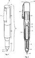
Fig. 1 is a perspective view of a device that produces color on demand. -
Fig. 2 is a cross-sectional view of the device ofFIG. 1 . -
Fig. 3 is a perspective view of an embodiment of an ink supply system. -
Fig. 4 is a cross-sectional view of theFIG. 3 . -
Fig. 5 is a perspective view of another embodiment of an ink supply system. -
Fig. 6 is a cross-sectional view of theFIG. 5 . -
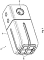
Fig. 7 is a perspective view of yet another ink supply system. - Aspects of the disclosure, as shown in
Figures 1 and 2 , involve adevice 100 that produces color on demand. Thedevice 100 may be a writing instrument, such as for example, a pen. While a writing instrument and pen are detailed herein, the device may be any similar device that may be capable of detecting color and reproducing the color being detected for use on paper or any surface known in the art for writing, drawing, etc. Thedevice 100 may include abody 110, having afirst end 112 and asecond end 114. Thefirst end 112 of thebody 110 may include atip 116 capable of performing the writing, drawing, etc. Thetip 116 may be, for example a felt tip, ball point tip or any other tip well known for writing, drawing, etc. Thesecond end 114 of thebody 110 may include aclip mechanism 118 or an eraser (not shown). - According to some aspects, the body 10 may include an
upper portion 110A, anintermediate portion 110B and alower portion 110C. The upper, intermediate andlower portions 110A-110C may be separable in any combination of two or three portions. For example, thebody 110 may include the upper 110A and thelower portion 110C where theupper portion 110A and theintermediate portion 110B may form theupper portion 110A or theintermediate portion 110B and thelower portion 110C may form thelower portion 110C. The upper, intermediate andlower portions 110A-110C may be connected to one another by snap-fit, twist/screw connection or by any other similar connection that is known in the art. According to other aspects, thebody 110 may also be a unitary or single component. Theclip 118 and the eraser (not shown) may be disposed on theupper portion 110A of thebody 110, and thetip 116 may be disposed at an end-most region of thelower portion 110C. - According to further aspects, the
device 100 may be capable of inspecting and capturing certain characteristics relating to a desired color. Hence, theupper portion 110A may also include an inspection and capturing tool, such as ascanner 120. Thescanner 120 may be, for example, at least a single-pixel camera positioned on an outer surface of theupper portion 110A of thebody 110 of thedevice 100. According to some aspects, the camera may also be, for example, a multi-pixel camera. Thescanner 120 may be operable for detecting and capturing the color to be reproduced. According to further aspects, thescanner 120 may be any similar mechanism that satisfies at least the following characteristics: 1) operable under controlled light and 2) capable of isolating the area being scanned and/or filtering unwanted light from the area being scanned. Additionally, thescanner 120 may be configured to be operable with other internal components of thedevice 100, such as for example, acontrol mechanism 122, abattery 124, and anink supply system 126 to facilitate the reproduction of a color on demand, as further detailed herein below. - According to some aspects, the
body 110 of thedevice 100 may include an interior that may house acontrol unit 122, abattery 124, anink supply system 126, anink reservoir 128, amixing tank 130, and a sensor (not shown), all disposed therein. As noted above, thescanner 120 may be disposed on the outer surface of thebody 110 near theupper portion 110A, while thecontrol unit 122,battery 124, andink reservoir 128 may be disposed in anintermediate portion 110B of thebody 110; and theink supply system 126, mixingtank 130 and sensor may be disposed in thelower portion 110C of thebody 110. According to other aspects, thecontrol unit 122,battery 124,ink supply system 126,ink reservoir 128, mixingtank 130 and sensor may be disposed in any portion of thebody 110 without deviating from the scope of the disclosure. - The
control unit 122 may be any electrical or mechanical system, such as for example, a radio frequency identification (RFID) circuit or other similar mechanism. According to other aspects, thecontrol unit 122 may also be a microelectro-mechanical system (MEMS). Thecontrol circuit 122 may be configured to be connected to and facilitate communication between thescanner 120 and theink supply system 126. - The
ink reservoir 128 may be onereservoir 128; however, according to some aspects, theink reservoir 128 may also be a plurality ofink reservoirs 128 such as, for example, as many as three, four, five, six ormore ink reservoirs 128. Theink reservoirs 128 may be configured to contain ink. According to some aspects, theink reservoirs 128 may each individually contain ink including, for example, colors that may be consistent with the RYB or CMY color models, such as for example red, yellow and blue or cyan, magenta and yellow. However, according to other aspects, theink reservoirs 128 may each individually contain ink including, for example, colors that may be consistent with the CMYK or CMYKW color models, such as cyan, magenta, yellow, and black or cyan, magenta, yellow, black and white. While RYB and CMY color models may be detailed, the present disclosure may be practiced using any similar color subtracting/adding system that allows the mixing of colors to obtain a desired color. - According to some aspects, the
ink reservoirs 128 may be configured to be disposed about thebattery 124 wherein theink reservoirs 128 may be, for example, concentric with thebattery 124. While a concentric arrangement with regards to theink reservoirs 128 andbattery 124 is detailed, according to other aspects, theink reservoirs 128 andbattery 124 may be positioned in any arrangement within the interior of thebody 110 of thedevice 100. Theink reservoirs 128 andbattery 124, upon the depletion of ink contained within thereservoirs 128 or upon depletion of the energy stored in thebattery 124 may be interchanged by the user. According to some aspects, thebattery 124 may be, for example, a size AAAA battery or equivalent battery and thebattery 124 may also be arechargeable battery 124. According to further aspects, theink reservoirs 128 andbattery 124 may be configured within ahousing 132 wherein thehousing 132 may be removed from thebody 110, as a single unit to allow for theink reservoirs 128 andbattery 124 to be each interchanged individually. However, according to other aspects, theink reservoirs 128 andbattery 124 may be contained within thebody 110 of thedevice 100 individually, without ahousing 132, each as a single unit, wherein theink reservoirs 128 andbattery 124 may be removed from thebody 110 separately, as individual units. Theink reservoirs 128 andbattery 124 may be configured to be operable with thecontrol unit 122. Theink reservoirs 128, upon communication with thecontrol unit 122, may be configured to provide a flow of ink to theink supply system 126 wherein an appropriate amount of each ink color may be supplied to the mixingtanks 130 to reproduce the color scanned and for distribution onto a piece of paper or similar surface. The ink may be gel, thermochromic and/or any other ink that is very well known in the art. A more detailed explanation of the ink is detailed below. - According to further aspects, the
ink supply system 126 may be similar to, for example, a micropump system, such as an inkjet distribution system. However, as detailed inFigs. 3 and 4 , according to other aspects, theink supply system 126, may be, for example, a thermal supply/distribution system 200. The thermal supply/distribution system 200 may include a body 210 having a number ofconnection ports 212 that may coincide with and may be in fluid communication with the number ofink reservoirs 128 contained within thebody 110 of thedevice 100. While only threeconnection ports 212 are shown inFigs. 3 and 4 , any number ofconnection ports 212 may be suitable to correlate with the number ofink reservoirs 128. For example, the thermal supply/distribution system 200 may include three, four, or even fiveconnection ports 212 to correlate with the cyan, magenta, yellow, black and/or white ink colors that may be used. The thermal supply/distribution system 200 may also include anink supply channel 214 that may fluidly communicate with adistribution port 216. Theink supply channels 214 may include a heating mechanism (not shown), for example, an electric mechanism capable of being connected to and for receiving a signal from thecontrol unit 122, such as an electrical wire. The heating mechanism may also be capable of generating heat to increase a temperature of the ink contained therein. - According to some aspects, the thermal supply/
distribution system 200 may be used with a thermochromic ink. The thermochromic ink, may contain, for example, a plurality of micro-spheres in a gel-type substance. The size of the spheres may be, for example, less that 1µm but not more than 5µm. Each one of the micro-spheres may contain three components including a dye, developer and solvent. The solvent, may be for example, a wax-type substance that may be somewhat solid. The micro-sphere may appear colored when the dye is attached with the developer and "blanked" or transparent when the dye and developer are detached. According to some aspects, the color may be "blanked" or transparent when the wax-type substance or solvent in the micro-sphere may be heated to a temperature of, for example, of approximately 70° C. As such, the heating mechanisms contained in theink supply channels 214 may cause the wax-type substance to melt thereby facilitating a change in color of the micro-sphere and initiating an adjustment/change of the color of the ink to be transformed/ reproduced. The transformed colors may be formulated as the result of a signal received from thecontrol unit 122 wherein the signal may facilitate the ink contained in theink reservoirs 128 to flow from and be emptied into theink supply channels 214 and later into themixing tank 130. However, according to further aspects, the adjusted and/or changed colors, also formulated as a result of a signal received from thecontrol unit 122, may be fluidly emptied from theink supply channels 214 into themixing tank 130. Themixing tank 130 may contain, for example, a series of swirl-type guiding conduit patterns (not shown) to assist with facilitating a mixture of the adjusted and/or changed colors to obtain the transformed color to be reproduced. Additionally, and according to other aspects, the series of swirl-type guiding conduit patterns may contain a series of holes and heating mechanisms. Themixing tank 130, being positioned at the end-most region of thelower portion 110C, may be positioned just prior to thetip 116. Hence, a mix of the adjusted and/or changed colors may be performed prior to the ink entering the series of holes formed in the series of swirl-type guiding conduit patterns. - According to some aspects, the ink may contain micro-spheres varying in size and the temperature provided by the heating mechanisms may also vary. Thus, the micro-sphere size and content may dictate the temperature transition of the individual micro-sphere. Depending upon the micro-sphere temperature transition, the thermal supply/
distribution system 200 may, at any given time, have a mix of individual micro-spheres separately changing state at different temperatures. - According to further aspects, the
tip 116 may include a sensor (not shown). A friction force may be applied to thetip 116 of thedevice 100 may be detected by the sensor which may initiate a communication to thecontrol unit 122. Thecontrol unit 122 may then, in turn, release a signal to the thermal supply/distribution system 200 and heating mechanisms contained in theink supply channels 214 or series of swirl-type guiding conduit patterns. As noted above, the small spheres containing the color and wax-type substance may be heated, thereby melting the wax and changing the color of the sphere. The spheres may be heated to a desired temperature wherein the color in one or more of theink supply channels 214 or series of swirl-type guiding conduit patterns is "blanked" or "partially blanked", at a temperature of, for example, of approximately 70° C. However, and simultaneously, the spheres of ink contained in the remainingsupply channels 214 or series of swirl-type guiding conduit patterns may be adjusted/changed according to a surge of electrical resistance received from the heating mechanisms until the desired scanned color is obtained. The surge of electrical resistance may be the result of a signal sent from thecontrol unit 122 to the heating mechanisms. The surge of electrical resistance may be the result of a signal received from the scanner and transmitted to thecontrol unit 122. Thecontrol unit 122 may then convert the signal received from the scanner to a resistance required to heat the heating mechanisms to the temperature needed to 'blank out" and/or change the color in the ink spheres contained in theink supply channels 214 or series of swirl-type guiding conduit patterns. The signal from thescanner 120 may be converted by thecontrol unit 122 to thereby attain controlled ratios of resistance to manipulate the temperature of the spheres according to the required parameters of the characteristics of the color desired to be reproduced. The 'blanked out", "partially blanked" and/or change ink may then flow into themixing tank 130 where the ink may then be mixed and transformed to obtain the scanned desired color. The scanned desired color may then be fluidly released through thetip 116 onto a paper, writing/drawing surface, etc. A release of the friction force from thetip 116 of thedevice 100, may also detected by the sensor. This release in friction force from thetip 116 may send another signal to thecontrol unit 122 wherein the resistance supplied to the heating elements may be halted. In the absence of heat and without an increase in temperature, the ink flow may be halted, the ink may return to the original colors, and the wax contained in the sphere may then return to the original somewhat solid state until thetip 116 encounters another friction force. According to some aspects, the sphere may return to the original color when the temperature may be, for example, less that minus 10°C. While a heated temperature of approximately 70° C may be detailed to "blank out" the color of the sphere and a temperature of minus 10°C may be detailed to return the sphere to the original color, these parameters are merely exemplary and may be adjusted according to the desired chemical aspects of the sphere and/or the contents contained within the sphere. - According to other aspects, the
ink supply system 126, may be, for example, a thermal supply/distribution system 300, as detailed inFigs. 5 and 6 . The thermal supply/distribution system 300 may include a plurality ofreservoirs 328 contained in ahousing 332. Theink supply channels 314 may be fluidly connected to correspondingink distribution chambers 324. The plurality ofreservoirs 328 may each be fluidly connected to correspondingink supply channels 314. The thermal supply/distribution system 300 may also include amixing tank 330 andtip 316. As such, and according to this aspect, themixing tank 330 andtip 316 may replace themixing tank 130 andtip 116, as shown inFigs. 1 and 2 . While only threeink reservoirs 328,ink supply channels 314 andink distribution chambers 324 are shown inFigs. 5 and 6 , thedevice 100 may include any number ofink reservoirs 328,ink supply channels 314 andink distribution chambers 324. For example, the thermal supply/distribution system 300 may include three, four, or even fiveink reservoirs 328,ink supply channels 314 andink distribution chambers 324 that may correlate with the cyan, magenta, yellow, black and/or white ink colors that may be used in the CMYK and CMKW color models. - The
ink distribution chambers 324 may include a heating mechanism (not shown). The heating mechanism used with theink distribution chambers 324 may include, for example, an electric mechanism capable of being connected to and for receiving a signal from thecontrol unit 122, such as an electrical wire. According to some aspects the heating mechanism may be wrapped about an external surface of theink distribution chambers 324. The heating mechanism may also be capable of generating heat to increase a temperature of the ink contained therein. - According to some aspects, the thermal supply/
distribution system 300 may also be used with a thermochromic ink. The thermochromic ink, may contain, for example, a plurality of micro-spheres in a gel-type substance. The size of the spheres may be, for example, less that 1µm but not more than 5µm. Each one of the micro-spheres may contain three components including a dye, developer and solvent. The solvent, may be for example, a wax-type substance. The micro-sphere may appear colored when the dye is attached with the developer and "blanked" or transparent when the dye and developer are detached. The wax-type substance may be somewhat solid and may be heated, by the heating mechanisms, to a desired temperature of, for example, approximately 70° C wherein the wax may melt thereby initiating a change in color and or "blank out" or "partial blank out" of the small spheres. The heating mechanism, being wrapped about an external surface of theink distribution chambers 324, may assist with melting the wax-type substance and may assist with facilitating an adjustment/change of the ink contained in theink distribution chambers 324 to thereby transform the color to the desired scanned color. The transformed colors may be formulated as the result of a signal received from thecontrol unit 122 wherein the ink contained in thereservoirs 328 may be allowed to flow from and be emptied into theink supply channels 314, and then into theink distribution chambers 324 where the ink is heated, and later into themixing tank 330. Themixing tank 330, being positioned at the end-most region of thelower portion 110C of thedevice 100, may be positioned just prior to thetip 316. Hence, a mix of the adjusted and/or changed colors may be performed just prior to the ink exiting thepin tip 316. - According to other aspects, the ink may contain micro-spheres varying in size and the temperature provided by the heating mechanisms may also vary. Thus, the micro-sphere size and content may dictate the temperature transition of the individual micro-sphere. Depending upon the micro-sphere temperature transition, the thermal supply/
distribution system 200 may, at any given time, have a mix of individual micro-spheres separately changing state at different temperatures. - According to further aspects, the
tip 316 may also include a sensor (not shown). A friction force may be applied to thetip 316 of thedevice 100 may be detected by the sensor which may initiate a communication to thecontrol unit 122. Thecontrol unit 122 may then, in turn, release a signal to the thermal supply/distribution system 300 and heating mechanisms disposed about theink distribution chambers 324. As noted above, the small spheres containing the color and wax-type substance may be heated, thereby melting the wax and changing the color of the sphere. The spheres may be heated to a desired temperature wherein the color in one or more ofink distribution chambers 324 is "blanked" or "partially blanked". According to some aspects, the color may be "blanked" or transparent when the wax-type substance or solvent in the micro-sphere may be heated to a temperature of, for example, of approximately 70° C. However, and simultaneously, the spheres of ink contained in the remainingink distribution chambers 324 may be adjusted/changed according to a surge of electrical resistance received from the heating mechanisms until the desired scanned color is obtained. The surge of electrical resistance may be the result of a signal sent from thecontrol unit 122 to the heating mechanisms. The surge of electrical resistance may be the result of a signal received from the scanner and transmitted to thecontrol unit 122. Thecontrol unit 122 may then convert the signal received from the scanner to a resistance required to heat the heating mechanisms to the temperature needed to 'blank out" and/or change the color in the ink spheres contained in theink distribution chambers 324. The 'blanked out", "partially blanked" and/or changed color contained in theink distribution chambers 324 may flow into themixing tank 330 and may fluidly communicate to obtain the scanned desired color. The scanned desired color may then flow from themixing tank 330 and may be released through thetip 316 onto a paper, writing/drawing surface, etc. A release of the friction force from thetip 316 of thedevice 100, may also detected by the sensor. This release in friction force from thetip 316 may send another signal to thecontrol unit 122 wherein the resistance supplied to the heating elements may be halted. In the absence of heat and without an increase in temperature, the wax contained in the sphere may then return to the original somewhat solid state until thetip 316 encounters another friction force. According to some aspects, the sphere may return to the original color when the temperature may be, for example, less that minus 10°C. While a heated temperature of approximately 70° C may be detailed to "blank out" the color of the sphere and a temperature of minus 10°C may be detailed to return the sphere to the original color, these parameters are merely exemplary and may be adjusted according to the desired chemical aspects of the sphere and/or the contents contained within the sphere. - According to further aspects, the sensor (not shown), may be positioned near the
lower portion 110C of thedevice 100 near thetip tip tip control unit 122 to "switch on" the ink flow. As such, ink flow may only be generated when the at least one spring and actuator may be compressed by the friction force and thecontrol unit 122 may be "switched on". Ink may not flow without the detection of a frictional force on thetip control unit 122 to "switch off' the ink flow in the absence of the frictional force. The inflow "switch on/switch off' feature may prevent leakage of the ink when thedevice 100 is not being used. - According to other aspects, the movement detector may be, for example a plurality of magnets (not shown) and sensors. The magnets and sensors may be disposed on the
tip tip tip control unit 122 to "switch on" the ink flow. As such, ink flow may only be generated when the magnets on thetip control unit 122 may be "switched on". Ink may not flow without the detection of a frictional force on thetip tip tip control unit 122 to "switch off' the ink flow in the absence of the frictional force. The inflow "switch on/switch off' feature may prevent leakage of the ink when thedevice 100 is not being used. - According to other aspects, the movement detector may be an accelerometer (not shown). An accelerometer may detect a more precise assessment of the speed of movement of the
device 100. As such, the accelerometer, detecting movement of the device, may cause the sensor to initiate sending a signal to thecontrol unit 122 to "switch on" the ink flow. The accelerometer detecting no movement, may, in turn, cause the sensor to initiate another signal to thecontrol unit 122 whereby thecontrol unit 122 may "switch off" the ink flow. Again, and as according to other aspects, the inflow "switch on/switch off' feature using the accelerometer may prevent leakage of the ink when thedevice 100 is not being used. - According to further aspects, the movement detector may be, for example, an optical sensor. The optical sensor may include a light and sensors wherein the light may be projected from the
tip control unit 122 to "switch on/switch off" ink flow. - According to further aspects, the movement detector may include, for example, a first chamber and a second chamber (not shown) formed between the mixing
tank tip tip tip tip tip - According to other aspects, a "stand-alone unit", such as for example, an external
ink supply system 400, as shown inFig. 7 , may be used to obtain a certain color on demand. The externalink supply system 400 may include abody 410 which may house at least a plurality ofink reservoirs 428 and a control unit (not shown) therein. Theink reservoirs 428 may be removable and interchanged by the user. Theink reservoirs 428 may be, for example, three, four, or even fiveink reservoirs 428. The color contained in the ink reservoirs may correlate, for example, with the cyan, magenta, yellow, black and/or white ink colors that may be used in the CMYK and CMYKW color models. - According to some aspects, the control unit of the external
ink supply system 400 may be operable to control the selection and proportions of colors needed from the CMYK and CMYKW color models to create or reproduce the requested color specified by the user on demand. According to further aspects, the externalink supply system 400 may also include a scanner and may be capable of communicating by being hardwired or through wireless communication such as, for example, Wi-Fi or Bluetooth with a personal electronic device such as a cellphone to reproduce a desired color on demand. Additionally, thebody 410 of the externalink supply system 400 may further include color selection mechanism such as, for example, a button, dial or slide indicator where the user may be able to physically personalize a color on demand by individual selection. - According to further aspects, the
body 410 of the externalink supply system 400 may include a plug or port 450. A desired color or user-created color may be mixed internally of the externalink supply system 400 and extracted from the externalink supply system 400 through the plug or port 450. The plug or port 450 may then be used to facilitate a transfer of the color desired, selected and/or created to the user. As such, and according to some aspects, a completed reproduced color may be retrieved from the externalink supply system 400 by the user simply connecting and/or positioning a device such as, for example, an empty cartridge, ink reservoir, bottle, cup, paint dish etc. with respect to the plug or port 450 to extract the desired color selected and/or created on demand from the plug or port 450. - It will be appreciated by those skilled in the art that changes could be made to the embodiments described above without departing from the broad inventive concept thereof. It is understood, therefore, that the present disclosure herein is not limited to the particular embodiments disclosed and is intended to cover modifications within the spirit and scope of the present disclosure.
Claims (10)
- A device (100; 400) for producing colors on demand, the device comprising:an inspection tool (120) for capturing the color;a plurality of ink reservoirs (128; 328; 428), each one of the plurality of ink reservoirs configured to hold a different color ink;an ink supply system (126) fluidly connected to the plurality of ink reservoirs (128; 328; 428), the ink supply system (126) being configured to receive ink from the plurality of ink reservoirs (128; 328; 428) and being configured to control the color of ink disposed therein;a mixing chamber (130; 330) fluidly connected to the ink supply system (126; 400) and being configured to mix the ink received from the ink supply system (126; 400); anda control unit (122) operatively connected to the plurality of ink reservoirs (128; 328; 428), the ink supply system (126) and the inspection tool (120) for controllably reproducing and dispersing the color captured by the inspection tool (120).
- The device (100) of claim 1, further including a sensor, the sensor being positioned adjacent to a tip (116; 316) disposed in the device.
- The device (100) of claim 2, wherein the sensor is a movement detector, the movement detector sensing a movement of the tip (116; 316) of the device.
- The device (100) of claim 3, wherein the movement detector is a spring and actuator.
- The device (100) of claim 3, wherein the movement detector includes magnets disposed near the tip (116: 316) of the device.
- The device (100) of claim 1, wherein the ink supply system (126) includes a heating mechanism to control the color of the ink disposed therein.
- The device (100) of claim 6, wherein the heating mechanism is an electric wire wrapped around chamber.
- The device (100) of claim 6, wherein the heating mechanism is an electric wire disposed in a supply channel (214; 314).
- The device (100) according to any of the preceding claims, wherein said device is a writing instrument.
- The device of claim 9, wherein the writing instrument is a pen.
Priority Applications (2)
| Application Number | Priority Date | Filing Date | Title |
|---|---|---|---|
| EP18305483.2A EP3556565B1 (en) | 2018-04-19 | 2018-04-19 | Device that produces color on demand |
| US16/388,176 US10899165B2 (en) | 2018-04-19 | 2019-04-18 | Device that produces color on demand |
Applications Claiming Priority (1)
| Application Number | Priority Date | Filing Date | Title |
|---|---|---|---|
| EP18305483.2A EP3556565B1 (en) | 2018-04-19 | 2018-04-19 | Device that produces color on demand |
Publications (2)
| Publication Number | Publication Date |
|---|---|
| EP3556565A1 true EP3556565A1 (en) | 2019-10-23 |
| EP3556565B1 EP3556565B1 (en) | 2022-10-12 |
Family
ID=62091806
Family Applications (1)
| Application Number | Title | Priority Date | Filing Date |
|---|---|---|---|
| EP18305483.2A Active EP3556565B1 (en) | 2018-04-19 | 2018-04-19 | Device that produces color on demand |
Country Status (2)
| Country | Link |
|---|---|
| US (1) | US10899165B2 (en) |
| EP (1) | EP3556565B1 (en) |
Families Citing this family (1)
| Publication number | Priority date | Publication date | Assignee | Title |
|---|---|---|---|---|
| CN114987088A (en) * | 2022-05-20 | 2022-09-02 | 王洋中 | Writing tool for color capture and copying writing |
Citations (11)
| Publication number | Priority date | Publication date | Assignee | Title |
|---|---|---|---|---|
| WO1993017872A1 (en) * | 1992-03-03 | 1993-09-16 | The Technology Partnership Limited | Electronic marking instrument |
| US5911533A (en) * | 1997-11-24 | 1999-06-15 | Eastman Kodak Company | Microfluidic writing pen |
| US6050680A (en) * | 1995-06-30 | 2000-04-18 | Canon Kabushiki Kaisha | Ink jet recording with mixing and storage of color inks with different mixing ratios |
| US20030138282A1 (en) * | 2002-01-24 | 2003-07-24 | Payne David M. | Writing instrument with user-controlled ink color |
| US20040125089A1 (en) * | 2002-12-30 | 2004-07-01 | Aiptek International Inc. | Electromagnetic induction pen-like device with writing function |
| US20060244805A1 (en) * | 2005-04-27 | 2006-11-02 | Ming-Hsiang Yeh | Multicolor pen |
| JP2009078568A (en) * | 2008-12-12 | 2009-04-16 | Fuji Xerox Co Ltd | Pen with writing control and writing control program for pen |
| EP2072277A1 (en) * | 2006-10-17 | 2009-06-24 | The Pilot Ink Co., Ltd. | Writing implement and writing implement set |
| US20100061793A1 (en) * | 2008-01-16 | 2010-03-11 | Judith Bender | Million color pen |
| WO2010035836A1 (en) * | 2008-09-29 | 2010-04-01 | パイロットインキ株式会社 | Multi-color writing implement |
| DE102016009576A1 (en) * | 2016-08-05 | 2018-02-08 | Sumitomo Wiring Systems, Ltd. | cable processing |
Family Cites Families (7)
| Publication number | Priority date | Publication date | Assignee | Title |
|---|---|---|---|---|
| US6394598B1 (en) * | 1997-04-28 | 2002-05-28 | Binney & Smith Inc. | Ink jet marker |
| CA2388626C (en) * | 1999-10-25 | 2008-12-23 | Paul Lapstun | Electronically controllable pen with sensor |
| AU2003280094A1 (en) * | 2003-10-17 | 2005-05-05 | Societe Bic | A liquid jet head and a liquid ejecting instrument including such a liquid jet head |
| US20090154983A1 (en) * | 2007-12-12 | 2009-06-18 | University Of Southern California | Multi-color writing and painting instruments with single nib fed with user-selected colored ink |
| US10717313B2 (en) * | 2016-03-28 | 2020-07-21 | Nucoat, Inc. | Heated writing device for use with thermochromatic ink |
| JP6664472B2 (en) * | 2016-05-18 | 2020-03-13 | 株式会社日立製作所 | Printing apparatus and control method of printing apparatus |
| US10688523B2 (en) * | 2017-03-22 | 2020-06-23 | Crayola Llc | Solid marking material melting applicator wand |
-
2018
- 2018-04-19 EP EP18305483.2A patent/EP3556565B1/en active Active
-
2019
- 2019-04-18 US US16/388,176 patent/US10899165B2/en not_active Expired - Fee Related
Patent Citations (11)
| Publication number | Priority date | Publication date | Assignee | Title |
|---|---|---|---|---|
| WO1993017872A1 (en) * | 1992-03-03 | 1993-09-16 | The Technology Partnership Limited | Electronic marking instrument |
| US6050680A (en) * | 1995-06-30 | 2000-04-18 | Canon Kabushiki Kaisha | Ink jet recording with mixing and storage of color inks with different mixing ratios |
| US5911533A (en) * | 1997-11-24 | 1999-06-15 | Eastman Kodak Company | Microfluidic writing pen |
| US20030138282A1 (en) * | 2002-01-24 | 2003-07-24 | Payne David M. | Writing instrument with user-controlled ink color |
| US20040125089A1 (en) * | 2002-12-30 | 2004-07-01 | Aiptek International Inc. | Electromagnetic induction pen-like device with writing function |
| US20060244805A1 (en) * | 2005-04-27 | 2006-11-02 | Ming-Hsiang Yeh | Multicolor pen |
| EP2072277A1 (en) * | 2006-10-17 | 2009-06-24 | The Pilot Ink Co., Ltd. | Writing implement and writing implement set |
| US20100061793A1 (en) * | 2008-01-16 | 2010-03-11 | Judith Bender | Million color pen |
| WO2010035836A1 (en) * | 2008-09-29 | 2010-04-01 | パイロットインキ株式会社 | Multi-color writing implement |
| JP2009078568A (en) * | 2008-12-12 | 2009-04-16 | Fuji Xerox Co Ltd | Pen with writing control and writing control program for pen |
| DE102016009576A1 (en) * | 2016-08-05 | 2018-02-08 | Sumitomo Wiring Systems, Ltd. | cable processing |
Also Published As
| Publication number | Publication date |
|---|---|
| US20190322119A1 (en) | 2019-10-24 |
| US10899165B2 (en) | 2021-01-26 |
| EP3556565B1 (en) | 2022-10-12 |
Similar Documents
| Publication | Publication Date | Title |
|---|---|---|
| CA2388626C (en) | Electronically controllable pen with sensor | |
| US10899165B2 (en) | Device that produces color on demand | |
| EP3258349B1 (en) | Position indicator | |
| US20180017414A1 (en) | Data logger | |
| US5911533A (en) | Microfluidic writing pen | |
| CA3068712A1 (en) | Multi-cartridge vaporizer | |
| US20030063943A1 (en) | Universal pen with code sensor | |
| US20060244805A1 (en) | Multicolor pen | |
| KR102150243B1 (en) | Measurement system of roasted coffee color and mothod thereof | |
| KR101050054B1 (en) | Color pen using electroosmotic micropump | |
| US8042935B2 (en) | Micro-miniature fluid jetting device | |
| CN114199380A (en) | Color detection gun and method | |
| US20250044884A1 (en) | Electronic pen and cartridge-type electronic pen main body including an conductive center electrode and a peripheral electrode | |
| US9694587B2 (en) | Inkjet printing apparatus and ink cartridge mounting unit | |
| TWI649215B (en) | Liquid container, liquid consuming device and electrical connection body | |
| US8827432B2 (en) | Cartridge | |
| DE60037460T2 (en) | COVER MECHANISM FOR PEN PRESSURE HEAD | |
| CN105273978A (en) | DNA (deoxyribonucleic acid) sequencer reaction bin with variable sealing ring area | |
| US20250116643A1 (en) | Gas Detector | |
| CN110896656A (en) | PTZ control device and PTZ system | |
| JP2025011912A (en) | MEASUREMENT DEVICE, MEASUREMENT SYSTEM, AND METHOD FOR SUPPLYING POWER TO A MEASUREMENT DEVICE | |
| US20220152613A1 (en) | Storage device for storing a gas measuring device, storage device and gas detector system and method for storing the gas detector | |
| AU2005200188B2 (en) | Cartridge for an electronic pen | |
| TR201922241U5 (en) | INDICATOR MECHANISM FOR A MODULAR VALVE | |
| CN103832078A (en) | Solid ink stick having identical identifying features on a plurality of edges |
Legal Events
| Date | Code | Title | Description |
|---|---|---|---|
| PUAI | Public reference made under article 153(3) epc to a published international application that has entered the european phase |
Free format text: ORIGINAL CODE: 0009012 |
|
| STAA | Information on the status of an ep patent application or granted ep patent |
Free format text: STATUS: THE APPLICATION HAS BEEN PUBLISHED |
|
| AK | Designated contracting states |
Kind code of ref document: A1 Designated state(s): AL AT BE BG CH CY CZ DE DK EE ES FI FR GB GR HR HU IE IS IT LI LT LU LV MC MK MT NL NO PL PT RO RS SE SI SK SM TR |
|
| AX | Request for extension of the european patent |
Extension state: BA ME |
|
| STAA | Information on the status of an ep patent application or granted ep patent |
Free format text: STATUS: REQUEST FOR EXAMINATION WAS MADE |
|
| 17P | Request for examination filed |
Effective date: 20200417 |
|
| RBV | Designated contracting states (corrected) |
Designated state(s): AL AT BE BG CH CY CZ DE DK EE ES FI FR GB GR HR HU IE IS IT LI LT LU LV MC MK MT NL NO PL PT RO RS SE SI SK SM TR |
|
| GRAP | Despatch of communication of intention to grant a patent |
Free format text: ORIGINAL CODE: EPIDOSNIGR1 |
|
| STAA | Information on the status of an ep patent application or granted ep patent |
Free format text: STATUS: GRANT OF PATENT IS INTENDED |
|
| RIC1 | Information provided on ipc code assigned before grant |
Ipc: C09D 11/50 20140101ALI20220407BHEP Ipc: B43K 5/18 20060101ALI20220407BHEP Ipc: B43K 5/02 20060101ALI20220407BHEP Ipc: B43K 29/08 20060101ALI20220407BHEP Ipc: B41J 2/21 20060101AFI20220407BHEP |
|
| INTG | Intention to grant announced |
Effective date: 20220425 |
|
| GRAS | Grant fee paid |
Free format text: ORIGINAL CODE: EPIDOSNIGR3 |
|
| GRAA | (expected) grant |
Free format text: ORIGINAL CODE: 0009210 |
|
| STAA | Information on the status of an ep patent application or granted ep patent |
Free format text: STATUS: THE PATENT HAS BEEN GRANTED |
|
| RAP3 | Party data changed (applicant data changed or rights of an application transferred) |
Owner name: SOCIETE BIC |
|
| AK | Designated contracting states |
Kind code of ref document: B1 Designated state(s): AL AT BE BG CH CY CZ DE DK EE ES FI FR GB GR HR HU IE IS IT LI LT LU LV MC MK MT NL NO PL PT RO RS SE SI SK SM TR |
|
| REG | Reference to a national code |
Ref country code: GB Ref legal event code: FG4D |
|
| REG | Reference to a national code |
Ref country code: CH Ref legal event code: EP |
|
| REG | Reference to a national code |
Ref country code: DE Ref legal event code: R096 Ref document number: 602018041638 Country of ref document: DE |
|
| REG | Reference to a national code |
Ref country code: IE Ref legal event code: FG4D |
|
| REG | Reference to a national code |
Ref country code: AT Ref legal event code: REF Ref document number: 1523928 Country of ref document: AT Kind code of ref document: T Effective date: 20221115 |
|
| REG | Reference to a national code |
Ref country code: LT Ref legal event code: MG9D |
|
| REG | Reference to a national code |
Ref country code: NL Ref legal event code: MP Effective date: 20221012 |
|
| REG | Reference to a national code |
Ref country code: AT Ref legal event code: MK05 Ref document number: 1523928 Country of ref document: AT Kind code of ref document: T Effective date: 20221012 |
|
| PG25 | Lapsed in a contracting state [announced via postgrant information from national office to epo] |
Ref country code: NL Free format text: LAPSE BECAUSE OF FAILURE TO SUBMIT A TRANSLATION OF THE DESCRIPTION OR TO PAY THE FEE WITHIN THE PRESCRIBED TIME-LIMIT Effective date: 20221012 |
|
| PG25 | Lapsed in a contracting state [announced via postgrant information from national office to epo] |
Ref country code: SE Free format text: LAPSE BECAUSE OF FAILURE TO SUBMIT A TRANSLATION OF THE DESCRIPTION OR TO PAY THE FEE WITHIN THE PRESCRIBED TIME-LIMIT Effective date: 20221012 Ref country code: PT Free format text: LAPSE BECAUSE OF FAILURE TO SUBMIT A TRANSLATION OF THE DESCRIPTION OR TO PAY THE FEE WITHIN THE PRESCRIBED TIME-LIMIT Effective date: 20230213 Ref country code: NO Free format text: LAPSE BECAUSE OF FAILURE TO SUBMIT A TRANSLATION OF THE DESCRIPTION OR TO PAY THE FEE WITHIN THE PRESCRIBED TIME-LIMIT Effective date: 20230112 Ref country code: LT Free format text: LAPSE BECAUSE OF FAILURE TO SUBMIT A TRANSLATION OF THE DESCRIPTION OR TO PAY THE FEE WITHIN THE PRESCRIBED TIME-LIMIT Effective date: 20221012 Ref country code: FI Free format text: LAPSE BECAUSE OF FAILURE TO SUBMIT A TRANSLATION OF THE DESCRIPTION OR TO PAY THE FEE WITHIN THE PRESCRIBED TIME-LIMIT Effective date: 20221012 Ref country code: ES Free format text: LAPSE BECAUSE OF FAILURE TO SUBMIT A TRANSLATION OF THE DESCRIPTION OR TO PAY THE FEE WITHIN THE PRESCRIBED TIME-LIMIT Effective date: 20221012 Ref country code: AT Free format text: LAPSE BECAUSE OF FAILURE TO SUBMIT A TRANSLATION OF THE DESCRIPTION OR TO PAY THE FEE WITHIN THE PRESCRIBED TIME-LIMIT Effective date: 20221012 |
|
| PGFP | Annual fee paid to national office [announced via postgrant information from national office to epo] |
Ref country code: FR Payment date: 20230321 Year of fee payment: 6 |
|
| PG25 | Lapsed in a contracting state [announced via postgrant information from national office to epo] |
Ref country code: RS Free format text: LAPSE BECAUSE OF FAILURE TO SUBMIT A TRANSLATION OF THE DESCRIPTION OR TO PAY THE FEE WITHIN THE PRESCRIBED TIME-LIMIT Effective date: 20221012 Ref country code: PL Free format text: LAPSE BECAUSE OF FAILURE TO SUBMIT A TRANSLATION OF THE DESCRIPTION OR TO PAY THE FEE WITHIN THE PRESCRIBED TIME-LIMIT Effective date: 20221012 Ref country code: LV Free format text: LAPSE BECAUSE OF FAILURE TO SUBMIT A TRANSLATION OF THE DESCRIPTION OR TO PAY THE FEE WITHIN THE PRESCRIBED TIME-LIMIT Effective date: 20221012 Ref country code: IS Free format text: LAPSE BECAUSE OF FAILURE TO SUBMIT A TRANSLATION OF THE DESCRIPTION OR TO PAY THE FEE WITHIN THE PRESCRIBED TIME-LIMIT Effective date: 20230212 Ref country code: HR Free format text: LAPSE BECAUSE OF FAILURE TO SUBMIT A TRANSLATION OF THE DESCRIPTION OR TO PAY THE FEE WITHIN THE PRESCRIBED TIME-LIMIT Effective date: 20221012 Ref country code: GR Free format text: LAPSE BECAUSE OF FAILURE TO SUBMIT A TRANSLATION OF THE DESCRIPTION OR TO PAY THE FEE WITHIN THE PRESCRIBED TIME-LIMIT Effective date: 20230113 |
|
| PGFP | Annual fee paid to national office [announced via postgrant information from national office to epo] |
Ref country code: GB Payment date: 20230321 Year of fee payment: 6 |
|
| REG | Reference to a national code |
Ref country code: DE Ref legal event code: R097 Ref document number: 602018041638 Country of ref document: DE |
|
| PG25 | Lapsed in a contracting state [announced via postgrant information from national office to epo] |
Ref country code: SM Free format text: LAPSE BECAUSE OF FAILURE TO SUBMIT A TRANSLATION OF THE DESCRIPTION OR TO PAY THE FEE WITHIN THE PRESCRIBED TIME-LIMIT Effective date: 20221012 Ref country code: RO Free format text: LAPSE BECAUSE OF FAILURE TO SUBMIT A TRANSLATION OF THE DESCRIPTION OR TO PAY THE FEE WITHIN THE PRESCRIBED TIME-LIMIT Effective date: 20221012 Ref country code: EE Free format text: LAPSE BECAUSE OF FAILURE TO SUBMIT A TRANSLATION OF THE DESCRIPTION OR TO PAY THE FEE WITHIN THE PRESCRIBED TIME-LIMIT Effective date: 20221012 Ref country code: DK Free format text: LAPSE BECAUSE OF FAILURE TO SUBMIT A TRANSLATION OF THE DESCRIPTION OR TO PAY THE FEE WITHIN THE PRESCRIBED TIME-LIMIT Effective date: 20221012 Ref country code: CZ Free format text: LAPSE BECAUSE OF FAILURE TO SUBMIT A TRANSLATION OF THE DESCRIPTION OR TO PAY THE FEE WITHIN THE PRESCRIBED TIME-LIMIT Effective date: 20221012 |
|
| PGFP | Annual fee paid to national office [announced via postgrant information from national office to epo] |
Ref country code: DE Payment date: 20230321 Year of fee payment: 6 |
|
| PLBE | No opposition filed within time limit |
Free format text: ORIGINAL CODE: 0009261 |
|
| STAA | Information on the status of an ep patent application or granted ep patent |
Free format text: STATUS: NO OPPOSITION FILED WITHIN TIME LIMIT |
|
| PG25 | Lapsed in a contracting state [announced via postgrant information from national office to epo] |
Ref country code: SK Free format text: LAPSE BECAUSE OF FAILURE TO SUBMIT A TRANSLATION OF THE DESCRIPTION OR TO PAY THE FEE WITHIN THE PRESCRIBED TIME-LIMIT Effective date: 20221012 Ref country code: AL Free format text: LAPSE BECAUSE OF FAILURE TO SUBMIT A TRANSLATION OF THE DESCRIPTION OR TO PAY THE FEE WITHIN THE PRESCRIBED TIME-LIMIT Effective date: 20221012 |
|
| 26N | No opposition filed |
Effective date: 20230713 |
|
| PG25 | Lapsed in a contracting state [announced via postgrant information from national office to epo] |
Ref country code: SI Free format text: LAPSE BECAUSE OF FAILURE TO SUBMIT A TRANSLATION OF THE DESCRIPTION OR TO PAY THE FEE WITHIN THE PRESCRIBED TIME-LIMIT Effective date: 20221012 |
|
| REG | Reference to a national code |
Ref country code: CH Ref legal event code: PL |
|
| PG25 | Lapsed in a contracting state [announced via postgrant information from national office to epo] |
Ref country code: LU Free format text: LAPSE BECAUSE OF NON-PAYMENT OF DUE FEES Effective date: 20230419 |
|
| REG | Reference to a national code |
Ref country code: BE Ref legal event code: MM Effective date: 20230430 |
|
| PG25 | Lapsed in a contracting state [announced via postgrant information from national office to epo] |
Ref country code: MC Free format text: LAPSE BECAUSE OF FAILURE TO SUBMIT A TRANSLATION OF THE DESCRIPTION OR TO PAY THE FEE WITHIN THE PRESCRIBED TIME-LIMIT Effective date: 20221012 |
|
| PG25 | Lapsed in a contracting state [announced via postgrant information from national office to epo] |
Ref country code: MC Free format text: LAPSE BECAUSE OF FAILURE TO SUBMIT A TRANSLATION OF THE DESCRIPTION OR TO PAY THE FEE WITHIN THE PRESCRIBED TIME-LIMIT Effective date: 20221012 Ref country code: LI Free format text: LAPSE BECAUSE OF NON-PAYMENT OF DUE FEES Effective date: 20230430 Ref country code: CH Free format text: LAPSE BECAUSE OF NON-PAYMENT OF DUE FEES Effective date: 20230430 |
|
| REG | Reference to a national code |
Ref country code: IE Ref legal event code: MM4A |
|
| PG25 | Lapsed in a contracting state [announced via postgrant information from national office to epo] |
Ref country code: BE Free format text: LAPSE BECAUSE OF NON-PAYMENT OF DUE FEES Effective date: 20230430 |
|
| PG25 | Lapsed in a contracting state [announced via postgrant information from national office to epo] |
Ref country code: IE Free format text: LAPSE BECAUSE OF NON-PAYMENT OF DUE FEES Effective date: 20230419 |
|
| PG25 | Lapsed in a contracting state [announced via postgrant information from national office to epo] |
Ref country code: IE Free format text: LAPSE BECAUSE OF NON-PAYMENT OF DUE FEES Effective date: 20230419 |
|
| PG25 | Lapsed in a contracting state [announced via postgrant information from national office to epo] |
Ref country code: IT Free format text: LAPSE BECAUSE OF FAILURE TO SUBMIT A TRANSLATION OF THE DESCRIPTION OR TO PAY THE FEE WITHIN THE PRESCRIBED TIME-LIMIT Effective date: 20221012 |
|
| REG | Reference to a national code |
Ref country code: DE Ref legal event code: R119 Ref document number: 602018041638 Country of ref document: DE |
|
| PG25 | Lapsed in a contracting state [announced via postgrant information from national office to epo] |
Ref country code: BG Free format text: LAPSE BECAUSE OF FAILURE TO SUBMIT A TRANSLATION OF THE DESCRIPTION OR TO PAY THE FEE WITHIN THE PRESCRIBED TIME-LIMIT Effective date: 20221012 |
|
| PG25 | Lapsed in a contracting state [announced via postgrant information from national office to epo] |
Ref country code: BG Free format text: LAPSE BECAUSE OF FAILURE TO SUBMIT A TRANSLATION OF THE DESCRIPTION OR TO PAY THE FEE WITHIN THE PRESCRIBED TIME-LIMIT Effective date: 20221012 |
|
| GBPC | Gb: european patent ceased through non-payment of renewal fee |
Effective date: 20240419 |
|
| PG25 | Lapsed in a contracting state [announced via postgrant information from national office to epo] |
Ref country code: DE Free format text: LAPSE BECAUSE OF NON-PAYMENT OF DUE FEES Effective date: 20241105 |
|
| PG25 | Lapsed in a contracting state [announced via postgrant information from national office to epo] |
Ref country code: GB Free format text: LAPSE BECAUSE OF NON-PAYMENT OF DUE FEES Effective date: 20240419 |
|
| PG25 | Lapsed in a contracting state [announced via postgrant information from national office to epo] |
Ref country code: FR Free format text: LAPSE BECAUSE OF NON-PAYMENT OF DUE FEES Effective date: 20240430 |
|
| PG25 | Lapsed in a contracting state [announced via postgrant information from national office to epo] |
Ref country code: GB Free format text: LAPSE BECAUSE OF NON-PAYMENT OF DUE FEES Effective date: 20240419 Ref country code: FR Free format text: LAPSE BECAUSE OF NON-PAYMENT OF DUE FEES Effective date: 20240430 Ref country code: DE Free format text: LAPSE BECAUSE OF NON-PAYMENT OF DUE FEES Effective date: 20241105 |
|
| PG25 | Lapsed in a contracting state [announced via postgrant information from national office to epo] |
Ref country code: CY Free format text: LAPSE BECAUSE OF FAILURE TO SUBMIT A TRANSLATION OF THE DESCRIPTION OR TO PAY THE FEE WITHIN THE PRESCRIBED TIME-LIMIT; INVALID AB INITIO Effective date: 20180419 |
|
| PG25 | Lapsed in a contracting state [announced via postgrant information from national office to epo] |
Ref country code: HU Free format text: LAPSE BECAUSE OF FAILURE TO SUBMIT A TRANSLATION OF THE DESCRIPTION OR TO PAY THE FEE WITHIN THE PRESCRIBED TIME-LIMIT; INVALID AB INITIO Effective date: 20180419 |
|
| PG25 | Lapsed in a contracting state [announced via postgrant information from national office to epo] |
Ref country code: TR Free format text: LAPSE BECAUSE OF FAILURE TO SUBMIT A TRANSLATION OF THE DESCRIPTION OR TO PAY THE FEE WITHIN THE PRESCRIBED TIME-LIMIT Effective date: 20221012 |