EP3556504A1 - Welding torch and all-position welding device - Google Patents
Welding torch and all-position welding device Download PDFInfo
- Publication number
- EP3556504A1 EP3556504A1 EP17881150.1A EP17881150A EP3556504A1 EP 3556504 A1 EP3556504 A1 EP 3556504A1 EP 17881150 A EP17881150 A EP 17881150A EP 3556504 A1 EP3556504 A1 EP 3556504A1
- Authority
- EP
- European Patent Office
- Prior art keywords
- flow path
- electrode
- welding torch
- sleeve
- holder
- Prior art date
- Legal status (The legal status is an assumption and is not a legal conclusion. Google has not performed a legal analysis and makes no representation as to the accuracy of the status listed.)
- Granted
Links
Images







Classifications
-
- B—PERFORMING OPERATIONS; TRANSPORTING
- B23—MACHINE TOOLS; METAL-WORKING NOT OTHERWISE PROVIDED FOR
- B23K—SOLDERING OR UNSOLDERING; WELDING; CLADDING OR PLATING BY SOLDERING OR WELDING; CUTTING BY APPLYING HEAT LOCALLY, e.g. FLAME CUTTING; WORKING BY LASER BEAM
- B23K9/00—Arc welding or cutting
- B23K9/24—Features related to electrodes
- B23K9/28—Supporting devices for electrodes
- B23K9/29—Supporting devices adapted for making use of shielding means
- B23K9/291—Supporting devices adapted for making use of shielding means the shielding means being a gas
-
- B—PERFORMING OPERATIONS; TRANSPORTING
- B23—MACHINE TOOLS; METAL-WORKING NOT OTHERWISE PROVIDED FOR
- B23K—SOLDERING OR UNSOLDERING; WELDING; CLADDING OR PLATING BY SOLDERING OR WELDING; CUTTING BY APPLYING HEAT LOCALLY, e.g. FLAME CUTTING; WORKING BY LASER BEAM
- B23K9/00—Arc welding or cutting
- B23K9/16—Arc welding or cutting making use of shielding gas
- B23K9/164—Arc welding or cutting making use of shielding gas making use of a moving fluid
-
- B—PERFORMING OPERATIONS; TRANSPORTING
- B23—MACHINE TOOLS; METAL-WORKING NOT OTHERWISE PROVIDED FOR
- B23K—SOLDERING OR UNSOLDERING; WELDING; CLADDING OR PLATING BY SOLDERING OR WELDING; CUTTING BY APPLYING HEAT LOCALLY, e.g. FLAME CUTTING; WORKING BY LASER BEAM
- B23K9/00—Arc welding or cutting
- B23K9/16—Arc welding or cutting making use of shielding gas
- B23K9/167—Arc welding or cutting making use of shielding gas and of a non-consumable electrode
-
- B—PERFORMING OPERATIONS; TRANSPORTING
- B23—MACHINE TOOLS; METAL-WORKING NOT OTHERWISE PROVIDED FOR
- B23K—SOLDERING OR UNSOLDERING; WELDING; CLADDING OR PLATING BY SOLDERING OR WELDING; CUTTING BY APPLYING HEAT LOCALLY, e.g. FLAME CUTTING; WORKING BY LASER BEAM
- B23K9/00—Arc welding or cutting
- B23K9/02—Seam welding; Backing means; Inserts
- B23K9/028—Seam welding; Backing means; Inserts for curved planar seams
-
- B—PERFORMING OPERATIONS; TRANSPORTING
- B23—MACHINE TOOLS; METAL-WORKING NOT OTHERWISE PROVIDED FOR
- B23K—SOLDERING OR UNSOLDERING; WELDING; CLADDING OR PLATING BY SOLDERING OR WELDING; CUTTING BY APPLYING HEAT LOCALLY, e.g. FLAME CUTTING; WORKING BY LASER BEAM
- B23K9/00—Arc welding or cutting
- B23K9/24—Features related to electrodes
- B23K9/28—Supporting devices for electrodes
- B23K9/29—Supporting devices adapted for making use of shielding means
-
- B—PERFORMING OPERATIONS; TRANSPORTING
- B23—MACHINE TOOLS; METAL-WORKING NOT OTHERWISE PROVIDED FOR
- B23K—SOLDERING OR UNSOLDERING; WELDING; CLADDING OR PLATING BY SOLDERING OR WELDING; CUTTING BY APPLYING HEAT LOCALLY, e.g. FLAME CUTTING; WORKING BY LASER BEAM
- B23K9/00—Arc welding or cutting
- B23K9/24—Features related to electrodes
- B23K9/28—Supporting devices for electrodes
- B23K9/29—Supporting devices adapted for making use of shielding means
- B23K9/291—Supporting devices adapted for making use of shielding means the shielding means being a gas
- B23K9/296—Supporting devices adapted for making use of shielding means the shielding means being a gas using non-consumable electrodes
-
- B—PERFORMING OPERATIONS; TRANSPORTING
- B23—MACHINE TOOLS; METAL-WORKING NOT OTHERWISE PROVIDED FOR
- B23K—SOLDERING OR UNSOLDERING; WELDING; CLADDING OR PLATING BY SOLDERING OR WELDING; CUTTING BY APPLYING HEAT LOCALLY, e.g. FLAME CUTTING; WORKING BY LASER BEAM
- B23K10/00—Welding or cutting by means of a plasma
- B23K10/02—Plasma welding
-
- B—PERFORMING OPERATIONS; TRANSPORTING
- B23—MACHINE TOOLS; METAL-WORKING NOT OTHERWISE PROVIDED FOR
- B23K—SOLDERING OR UNSOLDERING; WELDING; CLADDING OR PLATING BY SOLDERING OR WELDING; CUTTING BY APPLYING HEAT LOCALLY, e.g. FLAME CUTTING; WORKING BY LASER BEAM
- B23K2101/00—Articles made by soldering, welding or cutting
- B23K2101/04—Tubular or hollow articles
- B23K2101/06—Tubes
-
- B—PERFORMING OPERATIONS; TRANSPORTING
- B23—MACHINE TOOLS; METAL-WORKING NOT OTHERWISE PROVIDED FOR
- B23K—SOLDERING OR UNSOLDERING; WELDING; CLADDING OR PLATING BY SOLDERING OR WELDING; CUTTING BY APPLYING HEAT LOCALLY, e.g. FLAME CUTTING; WORKING BY LASER BEAM
- B23K2101/00—Articles made by soldering, welding or cutting
- B23K2101/04—Tubular or hollow articles
- B23K2101/10—Pipe-lines
-
- B—PERFORMING OPERATIONS; TRANSPORTING
- B23—MACHINE TOOLS; METAL-WORKING NOT OTHERWISE PROVIDED FOR
- B23K—SOLDERING OR UNSOLDERING; WELDING; CLADDING OR PLATING BY SOLDERING OR WELDING; CUTTING BY APPLYING HEAT LOCALLY, e.g. FLAME CUTTING; WORKING BY LASER BEAM
- B23K2103/00—Materials to be soldered, welded or cut
- B23K2103/02—Iron or ferrous alloys
- B23K2103/04—Steel or steel alloys
-
- B—PERFORMING OPERATIONS; TRANSPORTING
- B23—MACHINE TOOLS; METAL-WORKING NOT OTHERWISE PROVIDED FOR
- B23K—SOLDERING OR UNSOLDERING; WELDING; CLADDING OR PLATING BY SOLDERING OR WELDING; CUTTING BY APPLYING HEAT LOCALLY, e.g. FLAME CUTTING; WORKING BY LASER BEAM
- B23K9/00—Arc welding or cutting
- B23K9/02—Seam welding; Backing means; Inserts
- B23K9/028—Seam welding; Backing means; Inserts for curved planar seams
- B23K9/0282—Seam welding; Backing means; Inserts for curved planar seams for welding tube sections
- B23K9/0286—Seam welding; Backing means; Inserts for curved planar seams for welding tube sections with an electrode moving around the fixed tube during the welding operation
-
- B—PERFORMING OPERATIONS; TRANSPORTING
- B23—MACHINE TOOLS; METAL-WORKING NOT OTHERWISE PROVIDED FOR
- B23K—SOLDERING OR UNSOLDERING; WELDING; CLADDING OR PLATING BY SOLDERING OR WELDING; CUTTING BY APPLYING HEAT LOCALLY, e.g. FLAME CUTTING; WORKING BY LASER BEAM
- B23K9/00—Arc welding or cutting
- B23K9/02—Seam welding; Backing means; Inserts
- B23K9/028—Seam welding; Backing means; Inserts for curved planar seams
- B23K9/0288—Seam welding; Backing means; Inserts for curved planar seams for welding of tubes to tube plates
-
- B—PERFORMING OPERATIONS; TRANSPORTING
- B23—MACHINE TOOLS; METAL-WORKING NOT OTHERWISE PROVIDED FOR
- B23K—SOLDERING OR UNSOLDERING; WELDING; CLADDING OR PLATING BY SOLDERING OR WELDING; CUTTING BY APPLYING HEAT LOCALLY, e.g. FLAME CUTTING; WORKING BY LASER BEAM
- B23K9/00—Arc welding or cutting
- B23K9/24—Features related to electrodes
- B23K9/28—Supporting devices for electrodes
- B23K9/285—Cooled electrode holders
Definitions
- the present invention relates to a welding torch suitable for an all-position welding device that performs butt welding of tubes, and an all-position welding device including the welding torch.
- an all-position welding device which automatically performs butt welding between tubes.
- Such an all-position welding device may be used, for example, in the manufacture of an apparatus in which a plurality of tubes are arranged at a narrow pitch, such as a boiler panel.
- PTL 1 discloses a welding torch capable of passing through such a narrow gap as described above, and an all-position welding device including the welding torch.
- the welding torch of PTL 1 includes a non-consumable electrode, a collet into which the non-consumable electrode is inserted, a torch body, and a highly rigid porous ring.
- the torch body has a ceiling wall which is penetrated by the collet, and a body which encloses the ceiling wall and a shielding gas flow path facing the collet.
- the porous ring is joined to the body of the torch body so as to close the shielding gas flow path, and has a tapered inner peripheral surface that comes into contact with the distal end of the collet.
- the non-consumable electrode is held by the collet by the diameter of the distal end of the collet into which the non-consumable electrode is inserted being reduced by the inner peripheral surface of the porous ring.
- the porous ring of the welding torch of PTL 1 is a rigid body having a porosity of 30 to 60%.
- the porous ring is integrally formed on the torch body by, for example, pulse-wise irradiating a metal powder used as a raw material with a laser beam using a 3D printer.
- a welding torch includes the gas lens of a lattice structure that straightens a shielding gas.
- An all-position welding device performs butt welding of tubes, and includes the welding torch and a rotation mechanism for rotating the welding torch around the tubes.
- the gas lens has a lattice structure.
- the gas lens formed by using a 3D printer has regular gaps. Therefore, the porosity of the gas lens is stabilized, compared with the case where the gas lens is a porous body. Therefore, the improvement of the yield of the welding torch including the gas lens is expected.
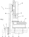
- the all-position welding device 1 shown in Figs. 1 and 2 automatically performs butt welding of tubes 10.
- the welding method may be, for example, tungsten inert gas (TIG) welding.
- the welding device 1 includes a welding torch 3, a rotation mechanism 2 for rotating the welding torch 3 around the tube 10, and three linear motion mechanisms for moving the welding torch 3 in a three-dimensional manner (a first linear motion mechanism 12, a second linear motion mechanism 14 and a third linear motion mechanism 16).
- the first linear motion mechanism 12 moves the welding torch 3 in the axial direction (e.g., the horizontal direction) of the tube 10
- the second linear motion mechanism 14 and the third linear motion mechanism 16 move the welding torch 3 in mutually orthogonal directions (for example, the horizontal direction and the vertical direction) on the plane orthogonal to the axial direction of the tube 10.
- a radial direction moving mechanism may be used which moves the welding torch 3 in the radial direction of the tube 10 with respect to a rotating member 21 described later.
- the welding torch 3 need not necessarily be moved in a three-dimensional manner, and may be moved in a two-dimensional manner on a plane orthogonal to the axial direction of the tube 10.
- the first linear motion mechanism 12 is attached to a base plate 11 parallel to the axial direction of the tube 10.
- the base plate 11 is provided with a clamp mechanism 18 for clamping the tube 10.
- the second linear motion mechanism 14 is fixed to the movable portion of the first linear motion mechanism 12 via a mounting seat 13.
- the third linear motion mechanism 16 is fixed to the movable portion of the second linear motion mechanism 14 via a mounting seat 15. Naturally, the positions of the first to third linear motion mechanisms 12, 14 and 16 can be interchanged with each other.
- the rotation mechanism 2 includes a plate-shaped table 20 orthogonal to the axial direction of the tube 10.
- the table 20 is fixed to the movable portion of the third linear motion mechanism 16 via a mounting seat 17.
- the substantially U-shaped rotating member 21 into which the tube 10 can be fitted is rotatably supported on the table 20.
- the table 20 is also formed with a notch 20a into which the tube 10 can be fitted.
- the rotating member 21 has an arc-shaped outer peripheral surface when viewed from the axial direction of the tube 10, and external teeth are formed on the outer peripheral surface.
- a motor 26 is attached to the table 20, on which a gear train is supported. The gear train transmits torque from a drive gear 25 fixed to the output shaft of the motor 26 to the rotating member 21. In Fig. 2 , the gear train and the motor 26 are omitted to simplify the figure.
- the gear train described above includes a large diameter first driven gear 24 engaging with the drive gear 25, a pair of second driven gears 23 engaging with the first driven gear 24, and a pair of third driven gears 22 engaging with the second driven gears 23 and the rotating member 21. With such a configuration, even if the opening of the rotating member 21 reaches one of the third driven gears 22, torque is transmitted to the rotating member 21 by the other third driven gear 22.
- the welding torch 3 is fixed, for example, to the center of the rotating member 21 so as to project in the axial direction of the tube 10.
- the welding torch 3 includes a plate-shaped torch body 4 orthogonal to the radial direction of the tube 10 and a non-consumable electrode 5 supported by the torch body 4 via an electrode holder 7.
- the non-consumable electrode 5 is used for generating an arc between the non-consumable electrode 5 and a welding area of the tube 10.
- the welding area is, for example, the bottom of the groove in the first layer and the previous layer in the second and subsequent layers when the groove is created at the joint of the tubes 10 and the welding layer is formed in many layers.
- a welding wire (not shown) is supplied from a wire supplying device (not shown) between the non-consumable electrode 5 and the welding area.
- the welding torch 3 is moved along the predetermined track by the first to third linear motion mechanisms 12, 14 and 16 while being rotated around the tube 10 by the rotation mechanism 2. At this time, the position of the welding torch 3 is finely adjusted by the first to third linear motion mechanisms 12, 14 and 16 so that the distance from the non-consumable electrode 5 to the welding area is a predetermined value.
- the rotating member 21 has conductivity
- the welding torch 3 including the torch body 4 and the non-consumable electrode 5 held thereby has conductivity
- the rotating member 21 supporting the welding torch 3 also has conductivity.
- Notches for tube insertion are formed at appropriate positions in the table 20 which makes the rotating member 21 rotatable.
- a power supply brush (not shown) which is continuously connected to the back surface of the rotating member 21 while the rotating member 21 rotates once is provided between the rotating member 21 and the table 20. In this manner, power is supplied to the welding torch 3 from the power supply brush via the rotating member 21. Therefore, the lines connected to welding torch 3 can be reduced, and the total thickness of the torch peripheral configuration can be reduced.
- Fig. 3 is a plan view of the welding torch 3
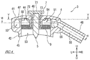
- Fig. 4 is a sectional view taken along line IV-IV of Fig. 3
- Fig. 5 is a sectional view taken along line V-V of Fig. 4
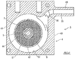
- Fig. 6 is a sectional view taken along line VI-VI of Fig. 4 .
- the welding torch 3 includes the non-consumable electrode 5, the electrode holder 7, and the torch body 4.
- the axial direction of the non-consumable electrode 5 is parallel to the radial direction of the tube 10.
- the non-consumable electrode 5 is held by the electrode holder 7, and the electrode holder 7 is inserted into a sleeve 44 formed in the torch body 4.
- Figs. 3 to 6 the welding torch 3 includes the non-consumable electrode 5, the electrode holder 7, and the torch body 4.
- the axial direction of the non-consumable electrode 5 is parallel to the radial direction of the tube 10.
- the non-consumable electrode 5 is held by the electrode holder 7, and the electrode holder 7 is inserted into a sleeve 44 formed in the torch body 4.
- the axial direction of the non-consumable electrode 5 may be referred to as the upward (U) and downward (D) direction, (the distal end is downward, the opposite thereof is upward), the axial direction of the tube 10 may be referred to as the forward (F) and back (B) direction, and the direction orthogonal to the above two directions may be referred to as the left (L) and right (R) direction.
- the electrode holder 7 includes a hexagonal plate-shaped head 71 orthogonal to the axial direction of the non-consumable electrode 5, and a holder cylinder portion 72 extending downward from the head 71.
- the non-consumable electrode 5 is inserted into the holder cylinder portion 72 from below the holder cylinder portion 72.
- the non-consumable electrode 5 inserted into the electrode holder 7 has a distal end of the non-consumable electrode 5, extending from the electrode holder 7.
- a screw thread 73 is formed on the outer peripheral surface of the holder cylinder portion 72. Further, a slit (not shown) for allowing a diameter reduction is formed at the distal end of the holder cylinder portion 72, and the holder cylinder portion 72 has a function as a collet.
- the torch body 4 integrally includes a base 40 having a substantially rectangular shape when viewed from the radial direction of the tube 10, and a joint portion 48 projecting rightward from the right side of the base 40.
- a hose (not shown) is connected to the joint portion 48, and the shielding gas is supplied to shielding gas flow paths 51 and 52 formed in the base 40 through the hose.
- the base 40 integrally includes the sleeve 44 that holds the electrode holder 7, a flow path forming portion 41 that forms the shielding gas flow paths 51 and 52 around the sleeve 44, a nozzle 42 forming a shielding gas guiding space 53 around the distal end of the non-consumable electrode 5 where the distal end extends from the electrode holder 7, and a gas lens 9 separating a shielding gas flow path 51 from the shielding gas guiding space 53.
- the sleeve 44 extends parallel to the radial direction of the tube 10 (that is, the axial direction of the non-consumable electrode 5).
- a threaded groove 46 is formed on the inner peripheral surface of the sleeve 44.
- the threaded groove 46 is screwed with the screw thread 73 of the electrode holder 7 which is screwed into the sleeve 44.
- the distal end (lower end) of the sleeve 44 has a tapered shape that is tapered downward.
- the holder cylinder portion 72 is pressurized in the direction of diameter reduction from the distal end of the sleeve 44, so that the non-consumable electrode 5 is held by the electrode holder 7.
- the flow path forming portion 41 forms the shielding gas flow paths 51 and 52 around the sleeve 44.
- the shielding gas flow paths 51 and 52 according to the present embodiment include an inner peripheral flow path 51 and an outer peripheral flow path 52.
- the inner peripheral flow path 51 is an annular flow path formed around the sleeve 44 and faces the gas lens 9.
- the outer peripheral flow path 52 is an annular passage formed around the inner peripheral flow path 51.
- the outer peripheral flow path 52 is connected to a flow path 55 of the joint portion 48 by a connection flow path 56.
- the inner peripheral flow path 51 and the outer peripheral flow path 52 are separated by a partition 47.
- a communication port 50 is formed, which communicates the inner peripheral flow path 51 and the outer peripheral flow path 52, and allows the shielding gas to flow from the outer peripheral flow path 52 into the inner peripheral flow path 51.
- a plurality of communication ports 50 are provided in the partition 47 so as to be dispersed in the circumferential direction, and the shielding gas flows from the entire periphery of the inner peripheral flow path 51 into the inside thereof.
- Each communication port 50 is provided at the upper portion of the partition 47 and at a position closer to the ceiling of the inner peripheral flow path 51, in other words, at a position further away from the gas lens 9.
- the connection flow path 56 is connected to the outer peripheral flow path 52 below the communication port 50. Therefore, the flow of the shielding gas flowing from the connection flow path 56 into the outer peripheral flow path 52 comes into contact with the partition 47. This prevents the shielding gas from flowing directly into the inner peripheral flow path 51 through the communication port 50.
- the ceiling of the inner peripheral flow path 51 is smoothly continuous with the proximal end of the sleeve 44, and the boundary between the proximal end of the sleeve 44 and the ceiling of the inner peripheral flow path 51 is connected with a curved surface.
- the curved surface portion formed on the wall forming the inner peripheral flow path 51 in this manner functions as a guide portion 54 for deflecting the flow of the shielding gas flowing from the outer peripheral flow path 52 into the inner peripheral flow path 51 toward the gas lens 9.
- the nozzle 42 which includes a circumferential lip 45 projecting downward from the flow path forming portion 41 is provided below the flow path forming portion 41.
- the inner peripheral wall of the nozzle 42 and the partition 47 are continuous in the axial direction of the non-consumable electrode 5.
- the distal end (lower end) of the lip 45 is located above the distal end of the non-consumable electrode 5 and below the distal end of the sleeve 44.
- the distal end of the lip 45 is curved along the outer peripheral surface of the facing tube 10.
- the lip 45 extends the distance from the gas lens 9 to the opening edge of the nozzle 42, that is, the length of the nozzle 42.
- the nozzle 42 forms the shielding gas guiding space 53 on the inner peripheral side thereof.
- the shielding gas flowing out of the gas lens 9 is straightened so as to flow in a laminar flow parallel to the extending direction of the nozzle 42, that is, the axial direction of the non-consumable electrode 5 without being diffused.
- the gas lens 9 straightens the shielding gas in a laminar flow, and separates the inner peripheral flow path 51 from the shielding gas guiding space 53.
- the gas lens 9 has a hollow disk shape centered on the non-consumable electrode 5.
- the inner peripheral portion of the gas lens 9 is connected to the outer peripheral surface of the distal end of the sleeve 44, and the outer peripheral portion of the gas lens 9 is connected to the inner peripheral surface of the nozzle 42 (or the inner peripheral surface of the partition 47).
- the gas lens 9 will be described in detail later.
- the torch body 4 consists of conductive metals, and is manufactured by metal 3D printer.
- the joint portion 48 does not necessarily have to be integrally formed on the torch body 4, and may be joined to the torch body 4 by welding or a screw structure.
- a laser beam is radiated onto the metal powder as a raw material, for example.
- the radiation of the laser light melts the metal powder and fuses the molten metal powder to produce a solid structure.
- the material of the metal powder is, for example, copper and copper alloy, steel, stainless steel, aluminum, titanium, nickel alloy and the like.
- the shielding gas guided through the flow path 55 of the joint portion 48 first flows into the outer peripheral flow path 52 through the connection flow path 56.
- the shielding gas diffused to the outer peripheral flow path 52 flows into the inner peripheral flow path 51 through the communication port 50.
- the flow of the shielding gas flowing into the inner peripheral flow path 51 is directed from the communication port 50 to the sleeve 44, comes into contact with the guide portion 54 located at the boundary between the ceiling of the inner peripheral flow path 51 and the sleeve 44, and is guided to the curved surface of the guide portion 54 to change its direction, and goes to the gas lens 9.
- the shielding gas is straightened while passing through the gas lens 9 to form a laminar flow, and flows out to the shielding gas guiding space 53 to spout from the distal end of the nozzle 42 toward the tube 10.
- Fig. 7 is a plan view of the gas lens 9
- Fig. 8 is a partial enlarged plan view of the gas lens 9
- Fig. 9 is a sectional view taken along line IX-IX of Fig. 8
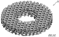
- Fig. 10 is a perspective view of the gas lens.
- the gas lens 9 has a lattice structure.
- the gas lens 9 is a three-dimensional mesh lattice in which elongated beams 90 and 92 are joined in a three-dimensional manner.
- the diameter ⁇ of the elongated beams 90 and 92 forming the lattice structure is about 0.2 mm at the minimum so that the elongated beams 90 and 92 can be manufactured by a metal 3D printer.
- mesh sheets 91 formed by joining cross beams 90 in a planar manner are stacked in the axial direction of the non-consumable electrode 5 with different phases. Furthermore, the lattice points of the mesh sheets 91 vertically stacked are joined by vertical beams 92.
- the gas lens 9 having such a lattice structure has regular gaps formed by the beams 90 and 92.
- a lattice of four cells of the mesh sheet 91 is shown, and a state in which a plurality of the mesh sheets 91 are stacked in the thickness direction with different phases is shown.
- a three-dimensional mesh lattice is apparent in which the lattice points of the mesh sheets 91 are joined together by oblique vertical beams 92.
- the inner peripheral portion of the gas lens 9 connected to the distal end of the sleeve 44 is required to have high rigidity, compared with the remaining portion of the gas lens 9 in order to withstand the pressure from the electrode holder 7 screwed into the sleeve 44. Therefore, the porosity of the inner peripheral portion of the gas lens 9, in particular, the porosity of the coupling portion with the sleeve 44, is kept at a low value (for example, 10% or less), compared with the remaining portion of the gas lens 9.
- the porosity can be determined from the apparent volume and the true density of the constituent material of the gas lens 9.
- the welding torch 3 of the present embodiment includes the gas lens 9 of a lattice structure that straightens a shielding gas.
- the all-position welding device 1 of the present embodiment includes the welding torch 3 and the rotation mechanism 2 for rotating the welding torch 3 around the tube 10.
- the gas lens 9 has a lattice structure.
- the gas lens 9 formed by using a 3D printer has regular gaps. Therefore, the porosity of the gas lens 9 is stabilized, compared with the case where the gas lens 9 is a porous body. Therefore, the improvement of the yield of the welding torch 3 including the gas lens 9 is expected.
- the gas lens 9 has a structure in which the mesh sheets 91 each formed by joining a plurality of beams 90 in a planar manner are stacked in the thickness direction with different phases. The lattice points of the stacked mesh sheets 91 are joined together by the vertical beams 92.
- the gas lens 9 of the welding torch 3 has a three-dimensional mesh lattice structure in which the cross beams 90 and the vertical beams 92 are joined together, but the present invention is not limited to this.
- the gas lens 9 may have a lattice structure that can form regular gaps using a 3D printer.
- the gas lens 9 may have a structure in which the mesh sheets 91 formed by joining a plurality of beams 90 in a planar manner are superimposed in several layers with different phases.
- the vertical beams 92 connecting the lattice points are provided between the layers of the mesh sheets 91, so that the shielding gas passing through the gas lens 9 is straightened by not only the cross beams 90 but also the vertical beams 92 of the lattice structure. Therefore, compared with the case where the vertical beams 92 are not provided, the same straightening effect can be obtained even if the number of the stacked mesh sheets 91 is reduced. In other words, compared with the case where the vertical beams 92 are not provided, the number of the stacked mesh sheets 91 can be reduced, and the thickness of the gas lens 9 (that is, the dimension of the non-consumable electrode 5 in the axial direction) can be suppressed.
- the welding torch 3 includes the non-consumable electrode 5, the electrode holder 7 into which the non-consumable electrode 5 is inserted, the sleeve 44 that holds the electrode holder 7, and the torch body 4 having the flow path forming portion 41 forming the shielding gas flow path 51 around the sleeve 44 and the nozzle 42 forming the shielding gas guiding space 53 around the distal end of the non-consumable electrode 5 where the distal end extends from the electrode holder 7.
- the gas lens 9 is provided to separate the shielding gas flow path 51 of the torch body 4 from the shielding gas guiding space 53.
- the inner peripheral portion of the gas lens 9 is connected to the outer peripheral surface of the sleeve 44, and the outer peripheral portion of the gas lens 9 is connected to the inner peripheral surface of the nozzle 42 (or the partition 47).
- the shielding gas that does not pass through the gas lens 9 from leaking from the gap between the shielding gas flow path 51 and the shielding gas guiding space 53.
- the gas lens 9 is integrally formed with other elements of the torch body 4 using a metal 3D printer, the inner peripheral portion of the gas lens 9 is supported by the rigid sleeve 44, and the outer peripheral portion of the gas lens 9 is supported by the rigid nozzle 42, so that the gas lens 9 is stably formed.
- the gas lens 9 is integrally formed with the sleeve 44 and the nozzle 42.
- the gas lens 9, the sleeve 44 and the nozzle 42 of the torch body 4 are formed by a metal 3D printer.
- the welding torch 3 in which a solid metal portion and the gas lens 9 having a higher porosity than that of the solid metal portion are combined with one torch body 4 using the forming technology using the metal 3D printer can be manufactured inexpensively.
- the shielding gas flow paths 51 and 52 include the inner peripheral flow path 51 formed around the sleeve 44 and facing the gas lens 9, and the outer peripheral flow path 52 formed around the inner peripheral flow path 51 and separated from the inner peripheral flow path 51 by the partition 47.
- the partition 47 is provided with the communication port 50 that allows the shielding gas to flow from the outer peripheral flow path 52 to the inner peripheral flow path 51.
- the shielding gas flow paths 51 and 52 into an inner/outer double structure of the inner peripheral flow path 51 and the outer peripheral flow path 52 provided on the outer peripheral side of the inner peripheral flow path 51, the shielding gas can be sufficiently laminarized even if the dimension (that is, the thickness) in the direction parallel to the axial direction of the non-consumable electrode 5 of the torch body 4 is reduced.
- the welding torch 3 can be flattened, that is, the thickness can be reduced, compared with the case where the shielding gas flow path is a single space.
- the guide portion 54 that deflects the flow of the shielding gas flowing from the outer peripheral flow path 52 into the inner peripheral flow path 51 toward the gas lens 9 is formed on the wall forming the inner peripheral flow path 51.
- the communication port 50 provided in the partition 47 between the inner peripheral flow path 51 and the outer peripheral flow path 52 is a hole penetrating the partition 47.
- the communication port 50 may be, for example, a slit or a tapered hole (see Fig. 12 ) which expands in diameter toward the inner peripheral flow path 51.
- the communication port 50 may be provided with an obstacle such as a swirl vane in order to provide flow resistance to the shielding gas passing through the communication port 50.
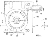
- Fig. 11 is a plan view of a welding torch 3A according to a second modification
- Fig. 12 is a sectional view taken along line XII-XII in Fig. 11
- Fig. 13 is a sectional view taken along line XIII-XIII in Fig. 12 .
- the opening ratio of the partition 47 of the second portion is larger than the opening ratio of the partition 47 of the first portion.
- the inflow portion of the shielding gas in the outer peripheral flow path 52 is a connection portion between the outer peripheral flow path 52 and the connection flow path 56.
- a plurality of communication ports 50 of the same size are formed in the partition 47, and the number of the communication ports 50 provided in the partition 47 of the second portion is larger than the number of the communication ports 50 provided in the partition 47 of the first portion.
- the opening ratio of the partition 47 of the second portion is larger than the opening ratio of the partition 47 of the first portion.
- the opening ratio of the partition 47 of the second portion may be larger than the opening ratio of the partition 47 of the first portion.
- the shielding gas that has flowed into the first portion of the outer peripheral flow path 52 is likely to spread around the second portion, so that the shielding gas can be diffused in the outer peripheral flow path 52.
- the electrode holder 7 has a function as a collet in the cylinder portion 72 thereof.
- the function as a collet can also be omitted from the electrode holder 7 as in a welding torch 3B according to the third modification demonstrated below.
- Fig. 14 is a plan view of the welding torch 3B according to the third modification.
- the welding torch 3B according to the third modification includes a non-consumable electrode 5B, an electrode holder 7B, and the torch body 4.
- the non-consumable electrode 5 is held by the electrode holder 7B, and the electrode holder 7B is inserted into the sleeve 44 formed in the torch body 4.
- the non-consumable electrode 5B includes an electrode shaft portion 5a and an electrode tapered portion 5b whose diameter gradually decreases from the electrode shaft portion 5a toward the distal end thereof.
- the electrode holder 7B integrally includes the holder cylinder portion 72, the screw thread 73 (first threaded portion) formed on the outer peripheral wall of the holder cylinder portion 72, and the holder head 71 that closes one of the end openings of the holder cylinder portion 72.
- the length of the holder cylinder portion 72 of the welding torch 3 according to the above embodiment is substantially the same as the length from a sleeve inlet 44a to a sleeve outlet 44b (see Fig. 4 )
- the length of the holder cylinder portion 72 of the welding torch 3B according to the present modification is shorter than the length from the sleeve inlet 44a to the sleeve outlet 44b. Therefore, the distal end of the holder cylinder portion 72 screwed into the sleeve 44 does not reach the sleeve outlet 44b.
- the holder cylinder portion 72 is not formed with a slot. That is, the holder cylinder portion 72 according to this modification does not have the function as a collet.
- the screw thread 73 is provided on the outer peripheral portion of the cylinder portion 72.
- the inner diameter of the holder cylinder portion 72 is slightly larger than the outer diameter of the electrode shaft portion 5a so that the electrode shaft portion 5a can be inserted loosely.
- the outer diameter of the electrode shaft portion 5a may be larger than the outer diameter of the non-consumable electrode 5 according to the above-described embodiment, and the former may be 1.5 times or more the latter.
- the sleeve 44 includes the sleeve inlet 44a into which the non-consumable electrode 5B and the holder cylinder portion 72 are inserted, the threaded groove 46 (second threaded portion) screwed with the screw thread 73, and the sleeve outlet 44b having an inner diameter larger than the minimum diameter and smaller than the maximum diameter of the electrode tapered portion 5b.
- the threaded groove 46 is provided in the sleeve 44, and the screw thread 73 is provided in the electrode holder 7B.
- the screw thread may be provided in the sleeve 44, and the threaded groove may be provided in the electrode holder 7B.
- the screw thread 73 of the electrode holder 7B is screwed with the threaded groove 46 of the sleeve 44, thereby allowing the movement of the electrode holder 7B in the insertion/removal direction. That is, when the electrode holder 7B rotates relative to the sleeve 44, the electrode holder 7B can be moved relative to the sleeve 44 in the insertion/removal direction.
- the vicinity of the sleeve outlet 44b has a tapered shape that gradually reduces toward the distal end.
- the gradient of this tapered shape is larger than the gradient of the electrode tapered portion 5b.
- the vicinity of the sleeve outlet 44b does not have to be tapered.
- the end face of the sleeve 44 on the sleeve outlet 44b side may be closed, and an opening serving as the sleeve outlet 44b may be provided.
- the length from the sleeve inlet 44a to the sleeve outlet 44b is longer than the length of the holder cylinder portion 72, and shorter than the length of the non-consumable electrode 5B. Therefore, the welding torch 3B inserted into the sleeve 44 from the sleeve inlet 44a has a distal end portion projecting from the sleeve outlet 44b.
- the movement of the non-consumable electrode 5B in the insertion direction into the sleeve 44 is restricted by the contact of the electrode tapered portion 5b with the opening edge of the sleeve outlet 44b. Therefore, the projection length of the non-consumable electrode 5B from the sleeve 44 can be adjusted by the length or the gradient of a tapered portion 59.
- the holder cylinder portion 72 is inserted into the sleeve 44, the electrode shaft portion 5a is inserted into the holder cylinder portion 72, an electrode tapered portion 55b comes into contact with the opening edge of the sleeve outlet 44b, and electrode shaft portion 5a comes contact with the holder head 71.
- the non-consumable electrode 5B is axially pressurized between the sleeve 44 and the electrode holder 7B. That is, the non-consumable electrode 5B is held by the torch body 4 by the axial force of the electrode holder 7B.
- the collet is omitted, but the non-consumable electrode 5B is held in a state where the relative position is fixed to the torch body 4 by the sleeve 44 and the electrode holder 7B.
- the electrode holder 7B since the electrode holder 7B is not equipped with the collet which is a consumable part, the electrode holder 7B can be reused when the non-consumable electrode 5B is replaced.
Landscapes
- Engineering & Computer Science (AREA)
- Physics & Mathematics (AREA)
- Plasma & Fusion (AREA)
- Mechanical Engineering (AREA)
- Arc Welding In General (AREA)
- Butt Welding And Welding Of Specific Article (AREA)
Abstract
Description
- The present invention relates to a welding torch suitable for an all-position welding device that performs butt welding of tubes, and an all-position welding device including the welding torch.
- Heretofore, an all-position welding device has been known which automatically performs butt welding between tubes. Such an all-position welding device may be used, for example, in the manufacture of an apparatus in which a plurality of tubes are arranged at a narrow pitch, such as a boiler panel.
PTL 1 discloses a welding torch capable of passing through such a narrow gap as described above, and an all-position welding device including the welding torch. - The welding torch of
PTL 1 includes a non-consumable electrode, a collet into which the non-consumable electrode is inserted, a torch body, and a highly rigid porous ring. The torch body has a ceiling wall which is penetrated by the collet, and a body which encloses the ceiling wall and a shielding gas flow path facing the collet. The porous ring is joined to the body of the torch body so as to close the shielding gas flow path, and has a tapered inner peripheral surface that comes into contact with the distal end of the collet. In this welding torch, the non-consumable electrode is held by the collet by the diameter of the distal end of the collet into which the non-consumable electrode is inserted being reduced by the inner peripheral surface of the porous ring. - PTL 1:
JP 2015-174141 A - The porous ring of the welding torch of
PTL 1 is a rigid body having a porosity of 30 to 60%. - The porous ring is integrally formed on the torch body by, for example, pulse-wise irradiating a metal powder used as a raw material with a laser beam using a 3D printer.
- However, when a porous ring is formed by the above method using a 3D printer, it is difficult to stably control the porosity of the porous ring. Therefore, the welding torch of
PTL 1 has room for improvement in terms of yield improvement. - Therefore, a welding torch according to an aspect of the present invention includes the gas lens of a lattice structure that straightens a shielding gas.
- An all-position welding device according to an aspect of the present invention performs butt welding of tubes, and includes the welding torch and a rotation mechanism for rotating the welding torch around the tubes.
- In the above-mentioned welding torch and all-position welding device, the gas lens has a lattice structure. By forming the gas lens in a lattice structure, the gas lens formed by using a 3D printer has regular gaps. Therefore, the porosity of the gas lens is stabilized, compared with the case where the gas lens is a porous body. Therefore, the improvement of the yield of the welding torch including the gas lens is expected.
- According to the present invention, it is possible to achieve an improvement in the yield of a welding torch including a gas lens formed using a 3D printer.
-
-
Fig. 1 is a front view of an all-position welding device equipped with a welding torch according to an embodiment of the present invention. -
Fig. 2 is a side view of the all-position welding device shown inFig. 1 . -
Fig. 3 is a plan view of a welding torch. -
Fig. 4 is a sectional view taken along line IV-IV ofFig. 3 . -
Fig. 5 is a sectional view taken along line V-V ofFig. 4 . -
Fig. 6 is a sectional view taken along line VI-VI ofFig. 4 . -
Fig. 7 is a plan view of a gas lens. -
Fig. 8 is a partial enlarged plan view of the gas lens. -
Fig. 9 is a sectional view taken along line IX-IX inFig. 8 . -
Fig. 10 is a perspective view of the gas lens. -
Fig. 11 is a plan view of a welding torch according to a second modification. -
Fig. 12 is a sectional view taken along line XII-XII ofFig. 11 . -
Fig. 13 is a sectional view taken along line XIII-XIII ofFig. 12 . -
Fig. 14 is a plan view of a welding torch according to a third modification. - Next, an embodiment of the present invention will be described with reference to the drawings. First, a schematic configuration of an all-
position welding device 1 according to an embodiment of the present invention will be described. - The all-
position welding device 1 shown inFigs. 1 and2 automatically performs butt welding oftubes 10. The welding method may be, for example, tungsten inert gas (TIG) welding. - The
welding device 1 includes awelding torch 3, arotation mechanism 2 for rotating thewelding torch 3 around thetube 10, and three linear motion mechanisms for moving thewelding torch 3 in a three-dimensional manner (a firstlinear motion mechanism 12, a secondlinear motion mechanism 14 and a third linear motion mechanism 16). - The first
linear motion mechanism 12 moves thewelding torch 3 in the axial direction (e.g., the horizontal direction) of thetube 10, the secondlinear motion mechanism 14 and the thirdlinear motion mechanism 16 move thewelding torch 3 in mutually orthogonal directions (for example, the horizontal direction and the vertical direction) on the plane orthogonal to the axial direction of thetube 10. However, in order to move thewelding torch 3 in a three-dimensional manner, it is not necessary to use three linear motion mechanisms. For example, instead of the secondlinear motion mechanism 14 and the thirdlinear motion mechanism 16, a radial direction moving mechanism may be used which moves thewelding torch 3 in the radial direction of thetube 10 with respect to a rotatingmember 21 described later. Alternatively, thewelding torch 3 need not necessarily be moved in a three-dimensional manner, and may be moved in a two-dimensional manner on a plane orthogonal to the axial direction of thetube 10. - The first
linear motion mechanism 12 is attached to abase plate 11 parallel to the axial direction of thetube 10. Thebase plate 11 is provided with aclamp mechanism 18 for clamping thetube 10. The secondlinear motion mechanism 14 is fixed to the movable portion of the firstlinear motion mechanism 12 via amounting seat 13. The thirdlinear motion mechanism 16 is fixed to the movable portion of the secondlinear motion mechanism 14 via amounting seat 15. Naturally, the positions of the first to thirdlinear motion mechanisms - The
rotation mechanism 2 includes a plate-shaped table 20 orthogonal to the axial direction of thetube 10. The table 20 is fixed to the movable portion of the thirdlinear motion mechanism 16 via amounting seat 17. The substantially U-shaped rotatingmember 21 into which thetube 10 can be fitted is rotatably supported on the table 20. Further, the table 20 is also formed with anotch 20a into which thetube 10 can be fitted. - The rotating
member 21 has an arc-shaped outer peripheral surface when viewed from the axial direction of thetube 10, and external teeth are formed on the outer peripheral surface. Amotor 26 is attached to the table 20, on which a gear train is supported. The gear train transmits torque from adrive gear 25 fixed to the output shaft of themotor 26 to the rotatingmember 21. InFig. 2 , the gear train and themotor 26 are omitted to simplify the figure. - The gear train described above includes a large diameter first driven
gear 24 engaging with thedrive gear 25, a pair of second driven gears 23 engaging with the first drivengear 24, and a pair of third drivengears 22 engaging with the second driven gears 23 and the rotatingmember 21. With such a configuration, even if the opening of the rotatingmember 21 reaches one of the third driven gears 22, torque is transmitted to the rotatingmember 21 by the other third drivengear 22. - The
welding torch 3 is fixed, for example, to the center of the rotatingmember 21 so as to project in the axial direction of thetube 10. Thewelding torch 3 includes a plate-shapedtorch body 4 orthogonal to the radial direction of thetube 10 and anon-consumable electrode 5 supported by thetorch body 4 via anelectrode holder 7. - The
non-consumable electrode 5 is used for generating an arc between thenon-consumable electrode 5 and a welding area of thetube 10. Here, the welding area is, for example, the bottom of the groove in the first layer and the previous layer in the second and subsequent layers when the groove is created at the joint of thetubes 10 and the welding layer is formed in many layers. A welding wire (not shown) is supplied from a wire supplying device (not shown) between thenon-consumable electrode 5 and the welding area. - In the
welding device 1 having the above configuration, thewelding torch 3 is moved along the predetermined track by the first to thirdlinear motion mechanisms tube 10 by therotation mechanism 2. At this time, the position of thewelding torch 3 is finely adjusted by the first to thirdlinear motion mechanisms non-consumable electrode 5 to the welding area is a predetermined value. - The rotating
member 21 has conductivity, thewelding torch 3 including thetorch body 4 and thenon-consumable electrode 5 held thereby has conductivity, and the rotatingmember 21 supporting thewelding torch 3 also has conductivity. Notches for tube insertion are formed at appropriate positions in the table 20 which makes the rotatingmember 21 rotatable. A power supply brush (not shown) which is continuously connected to the back surface of the rotatingmember 21 while the rotatingmember 21 rotates once is provided between the rotatingmember 21 and the table 20. In this manner, power is supplied to thewelding torch 3 from the power supply brush via the rotatingmember 21. Therefore, the lines connected towelding torch 3 can be reduced, and the total thickness of the torch peripheral configuration can be reduced. - Here, the configuration of the
welding torch 3 will be described in detail.Fig. 3 is a plan view of thewelding torch 3,Fig. 4 is a sectional view taken along line IV-IV ofFig. 3 ,Fig. 5 is a sectional view taken along line V-V ofFig. 4 , andFig. 6 is a sectional view taken along line VI-VI ofFig. 4 . - As shown in
Figs. 3 to 6 , thewelding torch 3 includes thenon-consumable electrode 5, theelectrode holder 7, and thetorch body 4. The axial direction of thenon-consumable electrode 5 is parallel to the radial direction of thetube 10. Thenon-consumable electrode 5 is held by theelectrode holder 7, and theelectrode holder 7 is inserted into asleeve 44 formed in thetorch body 4. Hereinafter, for convenience of explanation, as shown inFigs. 3 and4 , the axial direction of thenon-consumable electrode 5 may be referred to as the upward (U) and downward (D) direction, (the distal end is downward, the opposite thereof is upward), the axial direction of thetube 10 may be referred to as the forward (F) and back (B) direction, and the direction orthogonal to the above two directions may be referred to as the left (L) and right (R) direction. - The
electrode holder 7 includes a hexagonal plate-shapedhead 71 orthogonal to the axial direction of thenon-consumable electrode 5, and aholder cylinder portion 72 extending downward from thehead 71. Thenon-consumable electrode 5 is inserted into theholder cylinder portion 72 from below theholder cylinder portion 72. Thenon-consumable electrode 5 inserted into theelectrode holder 7 has a distal end of thenon-consumable electrode 5, extending from theelectrode holder 7. Ascrew thread 73 is formed on the outer peripheral surface of theholder cylinder portion 72. Further, a slit (not shown) for allowing a diameter reduction is formed at the distal end of theholder cylinder portion 72, and theholder cylinder portion 72 has a function as a collet. - The
torch body 4 integrally includes a base 40 having a substantially rectangular shape when viewed from the radial direction of thetube 10, and ajoint portion 48 projecting rightward from the right side of thebase 40. A hose (not shown) is connected to thejoint portion 48, and the shielding gas is supplied to shieldinggas flow paths - The base 40 integrally includes the
sleeve 44 that holds theelectrode holder 7, a flowpath forming portion 41 that forms the shieldinggas flow paths sleeve 44, anozzle 42 forming a shieldinggas guiding space 53 around the distal end of thenon-consumable electrode 5 where the distal end extends from theelectrode holder 7, and agas lens 9 separating a shieldinggas flow path 51 from the shieldinggas guiding space 53. - The
sleeve 44 extends parallel to the radial direction of the tube 10 (that is, the axial direction of the non-consumable electrode 5). A threadedgroove 46 is formed on the inner peripheral surface of thesleeve 44. The threadedgroove 46 is screwed with thescrew thread 73 of theelectrode holder 7 which is screwed into thesleeve 44. The distal end (lower end) of thesleeve 44 has a tapered shape that is tapered downward. Due to the tapered shape of thesleeve 44, when theelectrode holder 7 is screwed into the threadedgroove 46 on the inner periphery of thesleeve 44 in a state where thenon-consumable electrode 5 is inserted into theelectrode holder 7, theholder cylinder portion 72 is pressurized in the direction of diameter reduction from the distal end of thesleeve 44, so that thenon-consumable electrode 5 is held by theelectrode holder 7. - The flow
path forming portion 41 forms the shieldinggas flow paths sleeve 44. The shieldinggas flow paths peripheral flow path 51 and an outerperipheral flow path 52. The innerperipheral flow path 51 is an annular flow path formed around thesleeve 44 and faces thegas lens 9. The outerperipheral flow path 52 is an annular passage formed around the innerperipheral flow path 51. The outerperipheral flow path 52 is connected to aflow path 55 of thejoint portion 48 by aconnection flow path 56. - The inner
peripheral flow path 51 and the outerperipheral flow path 52 are separated by apartition 47. In thepartition 47, acommunication port 50 is formed, which communicates the innerperipheral flow path 51 and the outerperipheral flow path 52, and allows the shielding gas to flow from the outerperipheral flow path 52 into the innerperipheral flow path 51. In the present embodiment, a plurality ofcommunication ports 50 are provided in thepartition 47 so as to be dispersed in the circumferential direction, and the shielding gas flows from the entire periphery of the innerperipheral flow path 51 into the inside thereof. - Each
communication port 50 is provided at the upper portion of thepartition 47 and at a position closer to the ceiling of the innerperipheral flow path 51, in other words, at a position further away from thegas lens 9. Theconnection flow path 56 is connected to the outerperipheral flow path 52 below thecommunication port 50. Therefore, the flow of the shielding gas flowing from theconnection flow path 56 into the outerperipheral flow path 52 comes into contact with thepartition 47. This prevents the shielding gas from flowing directly into the innerperipheral flow path 51 through thecommunication port 50. - The ceiling of the inner
peripheral flow path 51 is smoothly continuous with the proximal end of thesleeve 44, and the boundary between the proximal end of thesleeve 44 and the ceiling of the innerperipheral flow path 51 is connected with a curved surface. The curved surface portion formed on the wall forming the innerperipheral flow path 51 in this manner functions as aguide portion 54 for deflecting the flow of the shielding gas flowing from the outerperipheral flow path 52 into the innerperipheral flow path 51 toward thegas lens 9. - The
nozzle 42 which includes acircumferential lip 45 projecting downward from the flowpath forming portion 41 is provided below the flowpath forming portion 41. In the present embodiment, the inner peripheral wall of thenozzle 42 and thepartition 47 are continuous in the axial direction of thenon-consumable electrode 5. The distal end (lower end) of thelip 45 is located above the distal end of thenon-consumable electrode 5 and below the distal end of thesleeve 44. The distal end of thelip 45 is curved along the outer peripheral surface of the facingtube 10. Thelip 45 extends the distance from thegas lens 9 to the opening edge of thenozzle 42, that is, the length of thenozzle 42. - The
nozzle 42 forms the shieldinggas guiding space 53 on the inner peripheral side thereof. In the shieldinggas guiding space 53, the shielding gas flowing out of thegas lens 9 is straightened so as to flow in a laminar flow parallel to the extending direction of thenozzle 42, that is, the axial direction of thenon-consumable electrode 5 without being diffused. - The
gas lens 9 straightens the shielding gas in a laminar flow, and separates the innerperipheral flow path 51 from the shieldinggas guiding space 53. Thegas lens 9 has a hollow disk shape centered on thenon-consumable electrode 5. The inner peripheral portion of thegas lens 9 is connected to the outer peripheral surface of the distal end of thesleeve 44, and the outer peripheral portion of thegas lens 9 is connected to the inner peripheral surface of the nozzle 42 (or the inner peripheral surface of the partition 47). Thegas lens 9 will be described in detail later. - In addition, the
torch body 4 according to the present embodiment consists of conductive metals, and is manufactured by metal 3D printer. However, thejoint portion 48 does not necessarily have to be integrally formed on thetorch body 4, and may be joined to thetorch body 4 by welding or a screw structure. When thetorch body 4 is manufactured with the metal 3D printer, a laser beam is radiated onto the metal powder as a raw material, for example. The radiation of the laser light melts the metal powder and fuses the molten metal powder to produce a solid structure. The material of the metal powder is, for example, copper and copper alloy, steel, stainless steel, aluminum, titanium, nickel alloy and the like. - In the
welding torch 3 configured as described above, the shielding gas guided through theflow path 55 of thejoint portion 48 first flows into the outerperipheral flow path 52 through theconnection flow path 56. The shielding gas diffused to the outerperipheral flow path 52 flows into the innerperipheral flow path 51 through thecommunication port 50. The flow of the shielding gas flowing into the innerperipheral flow path 51 is directed from thecommunication port 50 to thesleeve 44, comes into contact with theguide portion 54 located at the boundary between the ceiling of the innerperipheral flow path 51 and thesleeve 44, and is guided to the curved surface of theguide portion 54 to change its direction, and goes to thegas lens 9. The shielding gas is straightened while passing through thegas lens 9 to form a laminar flow, and flows out to the shieldinggas guiding space 53 to spout from the distal end of thenozzle 42 toward thetube 10. - Here, the configuration of the
gas lens 9 will be described in detail.Fig. 7 is a plan view of thegas lens 9,Fig. 8 is a partial enlarged plan view of thegas lens 9,Fig. 9 is a sectional view taken along line IX-IX ofFig. 8 , andFig. 10 is a perspective view of the gas lens. - As shown in
Figs. 7 to 10 , thegas lens 9 has a lattice structure. In other words, thegas lens 9 is a three-dimensional mesh lattice in which elongated beams 90 and 92 are joined in a three-dimensional manner. Note that the diameter Φ of theelongated beams elongated beams - In the
gas lens 9 according to the present embodiment,mesh sheets 91 formed by joiningcross beams 90 in a planar manner are stacked in the axial direction of thenon-consumable electrode 5 with different phases. Furthermore, the lattice points of themesh sheets 91 vertically stacked are joined byvertical beams 92. Thegas lens 9 having such a lattice structure has regular gaps formed by thebeams Fig. 8 , a lattice of four cells of themesh sheet 91 is shown, and a state in which a plurality of themesh sheets 91 are stacked in the thickness direction with different phases is shown. Further, inFig. 9 , a three-dimensional mesh lattice is apparent in which the lattice points of themesh sheets 91 are joined together by oblique vertical beams 92. - In the
gas lens 9 configured as described above, the inner peripheral portion of thegas lens 9 connected to the distal end of thesleeve 44 is required to have high rigidity, compared with the remaining portion of thegas lens 9 in order to withstand the pressure from theelectrode holder 7 screwed into thesleeve 44. Therefore, the porosity of the inner peripheral portion of thegas lens 9, in particular, the porosity of the coupling portion with thesleeve 44, is kept at a low value (for example, 10% or less), compared with the remaining portion of thegas lens 9. The porosity can be determined from the apparent volume and the true density of the constituent material of thegas lens 9. - As described above, the
welding torch 3 of the present embodiment includes thegas lens 9 of a lattice structure that straightens a shielding gas. - Further, the all-
position welding device 1 of the present embodiment includes thewelding torch 3 and therotation mechanism 2 for rotating thewelding torch 3 around thetube 10. - In the
welding torch 3 and the all-position welding device 1, thegas lens 9 has a lattice structure. By forming thegas lens 9 in a lattice structure, thegas lens 9 formed by using a 3D printer has regular gaps. Therefore, the porosity of thegas lens 9 is stabilized, compared with the case where thegas lens 9 is a porous body. Therefore, the improvement of the yield of thewelding torch 3 including thegas lens 9 is expected. - Further, in the
welding torch 3 of the above embodiment, thegas lens 9 has a structure in which themesh sheets 91 each formed by joining a plurality ofbeams 90 in a planar manner are stacked in the thickness direction with different phases. The lattice points of thestacked mesh sheets 91 are joined together by the vertical beams 92. - In the above embodiment, the
gas lens 9 of thewelding torch 3 has a three-dimensional mesh lattice structure in which the cross beams 90 and thevertical beams 92 are joined together, but the present invention is not limited to this. Thegas lens 9 may have a lattice structure that can form regular gaps using a 3D printer. For example, thegas lens 9 may have a structure in which themesh sheets 91 formed by joining a plurality ofbeams 90 in a planar manner are superimposed in several layers with different phases. However, as in the present embodiment, thevertical beams 92 connecting the lattice points are provided between the layers of themesh sheets 91, so that the shielding gas passing through thegas lens 9 is straightened by not only the cross beams 90 but also thevertical beams 92 of the lattice structure. Therefore, compared with the case where thevertical beams 92 are not provided, the same straightening effect can be obtained even if the number of thestacked mesh sheets 91 is reduced. In other words, compared with the case where thevertical beams 92 are not provided, the number of thestacked mesh sheets 91 can be reduced, and the thickness of the gas lens 9 (that is, the dimension of thenon-consumable electrode 5 in the axial direction) can be suppressed. - Further, the
welding torch 3 according to the present embodiment includes thenon-consumable electrode 5, theelectrode holder 7 into which thenon-consumable electrode 5 is inserted, thesleeve 44 that holds theelectrode holder 7, and thetorch body 4 having the flowpath forming portion 41 forming the shieldinggas flow path 51 around thesleeve 44 and thenozzle 42 forming the shieldinggas guiding space 53 around the distal end of thenon-consumable electrode 5 where the distal end extends from theelectrode holder 7. Thegas lens 9 is provided to separate the shieldinggas flow path 51 of thetorch body 4 from the shieldinggas guiding space 53. - In the
welding torch 3 according to the present embodiment, the inner peripheral portion of thegas lens 9 is connected to the outer peripheral surface of thesleeve 44, and the outer peripheral portion of thegas lens 9 is connected to the inner peripheral surface of the nozzle 42 (or the partition 47). - Thus, it is possible to prevent the shielding gas that does not pass through the
gas lens 9 from leaking from the gap between the shieldinggas flow path 51 and the shieldinggas guiding space 53. Also, when thegas lens 9 is integrally formed with other elements of thetorch body 4 using a metal 3D printer, the inner peripheral portion of thegas lens 9 is supported by therigid sleeve 44, and the outer peripheral portion of thegas lens 9 is supported by therigid nozzle 42, so that thegas lens 9 is stably formed. - Further, in the
welding torch 3 according to the present embodiment, thegas lens 9 is integrally formed with thesleeve 44 and thenozzle 42. In the present embodiment, thegas lens 9, thesleeve 44 and thenozzle 42 of thetorch body 4 are formed by a metal 3D printer. - As described above, the
welding torch 3 in which a solid metal portion and thegas lens 9 having a higher porosity than that of the solid metal portion are combined with onetorch body 4 using the forming technology using the metal 3D printer can be manufactured inexpensively. - Further, in the
welding torch 3 according to the present embodiment, the shieldinggas flow paths peripheral flow path 51 formed around thesleeve 44 and facing thegas lens 9, and the outerperipheral flow path 52 formed around the innerperipheral flow path 51 and separated from the innerperipheral flow path 51 by thepartition 47. Thepartition 47 is provided with thecommunication port 50 that allows the shielding gas to flow from the outerperipheral flow path 52 to the innerperipheral flow path 51. - In this way, by forming the shielding
gas flow paths peripheral flow path 51 and the outerperipheral flow path 52 provided on the outer peripheral side of the innerperipheral flow path 51, the shielding gas can be sufficiently laminarized even if the dimension (that is, the thickness) in the direction parallel to the axial direction of thenon-consumable electrode 5 of thetorch body 4 is reduced. As a result, thewelding torch 3 can be flattened, that is, the thickness can be reduced, compared with the case where the shielding gas flow path is a single space. - Further, in the
welding torch 3 according to the present embodiment, theguide portion 54 that deflects the flow of the shielding gas flowing from the outerperipheral flow path 52 into the innerperipheral flow path 51 toward thegas lens 9 is formed on the wall forming the innerperipheral flow path 51. - As a result, the flow of the shielding gas that has flowed into the inner
peripheral flow path 51 is efficiently guided to thegas lens 9 without colliding with the walls other than theguide portion 54 and without being diffused. - Although the preferred embodiment of the present invention has been described above, it is also possible to include modifications of the specific structure and/or function of the above embodiment in detail without departing from the spirit of the present invention. The above configuration can be modified, for example, as follows. In the description of the first to third modifications, the same or similar members as or to those of the embodiment described above are designated by the same reference numerals, and the description thereof will be omitted.
- In the
welding torch 3 according to the above-described embodiment, thecommunication port 50 provided in thepartition 47 between the innerperipheral flow path 51 and the outerperipheral flow path 52 is a hole penetrating thepartition 47. However, the aspect of thecommunication port 50 is not limited to this. Thecommunication port 50 may be, for example, a slit or a tapered hole (seeFig. 12 ) which expands in diameter toward the innerperipheral flow path 51. Also, thecommunication port 50 may be provided with an obstacle such as a swirl vane in order to provide flow resistance to the shielding gas passing through thecommunication port 50. - In the
welding torch 3 according to the embodiment, thecommunication ports 50 provided in thepartition 47 between the innerperipheral flow path 51 and the outerperipheral flow path 52 are arranged in thepartition 47 at equal intervals in the circumferential direction. However, the arrangement of thecommunication port 50 is not limited to the above embodiment, and may be provided in thepartition 47 disproportionately in the circumferential direction.Fig. 11 is a plan view of awelding torch 3A according to a second modification,Fig. 12 is a sectional view taken along line XII-XII inFig. 11 , andFig. 13 is a sectional view taken along line XIII-XIII inFig. 12 . In thewelding torch 3A according to the second modification shown inFigs. 11 to 13 , when the outerperipheral flow path 52 is divided in the circumferential direction into two portions consisting of a first portion including an inflow portion of the shielding gas and a remaining second portion, the opening ratio of thepartition 47 of the second portion is larger than the opening ratio of thepartition 47 of the first portion. Here, the inflow portion of the shielding gas in the outerperipheral flow path 52 is a connection portion between the outerperipheral flow path 52 and theconnection flow path 56. - In particular, as is clearly shown in
Figs. 11 and13 in thewelding torch 3A according to the second modification, a plurality ofcommunication ports 50 of the same size are formed in thepartition 47, and the number of thecommunication ports 50 provided in thepartition 47 of the second portion is larger than the number of thecommunication ports 50 provided in thepartition 47 of the first portion. As a result, the opening ratio of thepartition 47 of the second portion is larger than the opening ratio of thepartition 47 of the first portion. However, by making the opening area of thecommunication port 50 provided in thepartition 47 of the second portion larger than the opening area of thecommunication port 50 provided in thepartition 47 of the first portion, the opening ratio of thepartition 47 of the second portion may be larger than the opening ratio of thepartition 47 of the first portion. - As described above, by making the opening ratio of the
partition 47 of the second portion larger than the opening ratio of thepartition 47 of the first portion of the outerperipheral flow path 52, the shielding gas that has flowed into the first portion of the outerperipheral flow path 52 is likely to spread around the second portion, so that the shielding gas can be diffused in the outerperipheral flow path 52. - In the
welding torch 3 according to the above embodiment, theelectrode holder 7 has a function as a collet in thecylinder portion 72 thereof. However, the function as a collet can also be omitted from theelectrode holder 7 as in awelding torch 3B according to the third modification demonstrated below.Fig. 14 is a plan view of thewelding torch 3B according to the third modification. - The
welding torch 3B according to the third modification includes anon-consumable electrode 5B, anelectrode holder 7B, and thetorch body 4. Thenon-consumable electrode 5 is held by theelectrode holder 7B, and theelectrode holder 7B is inserted into thesleeve 44 formed in thetorch body 4. - The
non-consumable electrode 5B includes anelectrode shaft portion 5a and an electrode taperedportion 5b whose diameter gradually decreases from theelectrode shaft portion 5a toward the distal end thereof. - The
electrode holder 7B integrally includes theholder cylinder portion 72, the screw thread 73 (first threaded portion) formed on the outer peripheral wall of theholder cylinder portion 72, and theholder head 71 that closes one of the end openings of theholder cylinder portion 72. Although the length of theholder cylinder portion 72 of thewelding torch 3 according to the above embodiment is substantially the same as the length from asleeve inlet 44a to asleeve outlet 44b (seeFig. 4 ), the length of theholder cylinder portion 72 of thewelding torch 3B according to the present modification is shorter than the length from thesleeve inlet 44a to thesleeve outlet 44b. Therefore, the distal end of theholder cylinder portion 72 screwed into thesleeve 44 does not reach thesleeve outlet 44b. - Unlike the above-described embodiment, the
holder cylinder portion 72 is not formed with a slot. That is, theholder cylinder portion 72 according to this modification does not have the function as a collet. Thescrew thread 73 is provided on the outer peripheral portion of thecylinder portion 72. The inner diameter of theholder cylinder portion 72 is slightly larger than the outer diameter of theelectrode shaft portion 5a so that theelectrode shaft portion 5a can be inserted loosely. The outer diameter of theelectrode shaft portion 5a may be larger than the outer diameter of thenon-consumable electrode 5 according to the above-described embodiment, and the former may be 1.5 times or more the latter. - The
sleeve 44 includes thesleeve inlet 44a into which thenon-consumable electrode 5B and theholder cylinder portion 72 are inserted, the threaded groove 46 (second threaded portion) screwed with thescrew thread 73, and thesleeve outlet 44b having an inner diameter larger than the minimum diameter and smaller than the maximum diameter of the electrode taperedportion 5b. In this modification, the threadedgroove 46 is provided in thesleeve 44, and thescrew thread 73 is provided in theelectrode holder 7B. However, the screw thread may be provided in thesleeve 44, and the threaded groove may be provided in theelectrode holder 7B. Thescrew thread 73 of theelectrode holder 7B is screwed with the threadedgroove 46 of thesleeve 44, thereby allowing the movement of theelectrode holder 7B in the insertion/removal direction. That is, when theelectrode holder 7B rotates relative to thesleeve 44, theelectrode holder 7B can be moved relative to thesleeve 44 in the insertion/removal direction. - In the
sleeve 44 according to this modification, the vicinity of thesleeve outlet 44b has a tapered shape that gradually reduces toward the distal end. The gradient of this tapered shape is larger than the gradient of the electrode taperedportion 5b. However, the vicinity of thesleeve outlet 44b does not have to be tapered. For example, the end face of thesleeve 44 on thesleeve outlet 44b side may be closed, and an opening serving as thesleeve outlet 44b may be provided. - In the
welding torch 3B configured as described above, the length from thesleeve inlet 44a to thesleeve outlet 44b is longer than the length of theholder cylinder portion 72, and shorter than the length of thenon-consumable electrode 5B. Therefore, thewelding torch 3B inserted into thesleeve 44 from thesleeve inlet 44a has a distal end portion projecting from thesleeve outlet 44b. The movement of thenon-consumable electrode 5B in the insertion direction into thesleeve 44 is restricted by the contact of the electrode taperedportion 5b with the opening edge of thesleeve outlet 44b. Therefore, the projection length of thenon-consumable electrode 5B from thesleeve 44 can be adjusted by the length or the gradient of a tapered portion 59. - In the
welding torch 3B configured as described above, theholder cylinder portion 72 is inserted into thesleeve 44, theelectrode shaft portion 5a is inserted into theholder cylinder portion 72, an electrode tapered portion 55b comes into contact with the opening edge of thesleeve outlet 44b, andelectrode shaft portion 5a comes contact with theholder head 71. By screwing theelectrode holder 7B into thesleeve 44, thenon-consumable electrode 5B is axially pressurized between thesleeve 44 and theelectrode holder 7B. That is, thenon-consumable electrode 5B is held by thetorch body 4 by the axial force of theelectrode holder 7B. - As described above, in the
welding torch 3B according to the present modification, the collet is omitted, but thenon-consumable electrode 5B is held in a state where the relative position is fixed to thetorch body 4 by thesleeve 44 and theelectrode holder 7B. In thewelding torch 3B, since theelectrode holder 7B is not equipped with the collet which is a consumable part, theelectrode holder 7B can be reused when thenon-consumable electrode 5B is replaced. -
- 1
- all-position welding device
- 2
- rotation mechanism
- 3, 3A, 3B
- welding torch
- 4
- torch body
- 5, 5B
- non-consumable electrode
- 5a
- electrode shaft portion
- 5b
- electrode tapered portion
- 5t
- tapered portion
- 7, 7B
- electrode holder
- 71
- holder head
- 72
- holder cylinder portion
- 73
- screw thread
- 9
- gas lens
- 10
- tube
- 11
- base plate
- 12, 14, 16
- linear motion mechanism
- 18
- clamp mechanism
- 20
- table
- 21
- rotating member
- 22, 23, 24
- driven gear
- 25
- drive gear
- 26
- motor
- 40
- base
- 41
- flow path forming portion
- 42
- nozzle
- 44
- sleeve
- 44a
- sleeve inlet
- 44b
- sleeve outlet
- 45
- lip
- 46
- threaded groove
- 47
- partition
- 48
- joint portion
- 50
- communication port
- 51
- inner peripheral flow path (shielding gas flow passage)
- 52
- outer peripheral flow path (shielding gas flow passage)
- 53
- shielding gas guiding space
- 54
- guide portion
- 56
- connection flow path
- 90, 92
- beam
- 91
- mesh sheet
Claims (11)
- A welding torch comprising a gas lens of a lattice structure that straightens a shielding gas.
- The welding torch according to claim 1,
wherein the gas lens has a structure in which mesh sheets each formed by joining a plurality of beams in a planar manner are stacked in a thickness direction with different phases. - The welding torch according to claim 2,
wherein lattice points of the stacked mesh sheets are joined by a vertical beam. - The welding torch according to any one of claims 1 to 3, wherein the welding torch includes
a non-consumable electrode;
an electrode holder that holds the non-consumable electrode; and
a torch body including a sleeve into which the electrode holder is inserted, a flow path forming portion that forms a shielding gas flow path around the sleeve, and a nozzle that forms a shielding gas guiding space around a distal end of the non-consumable electrode, the distal end extending from the electrode holder,
wherein the gas lens is provided so as to separate the shielding gas flow path of the torch body from the shielding gas guiding space. - The welding torch according to claim 4,
wherein an inner peripheral portion of the gas lens is connected to an outer peripheral surface of the sleeve, and an outer peripheral portion of the gas lens is connected to an inner peripheral surface of the nozzle. - The welding torch according to claim 4 or 5,
wherein the gas lens is integrally formed with the sleeve and the nozzle. - The welding torch according to any one of claims 4 to 6,
wherein the shielding gas flow path includes an inner peripheral flow path formed around the sleeve and facing the gas lens, and an outer peripheral flow path formed around the inner peripheral flow path and separated from the inner peripheral flow path by a partition, and
wherein the partition is provided with a communication port for allowing inflow of a shielding gas from the outer peripheral flow path to the inner peripheral flow path. - The welding torch according to claim 7,
wherein when the outer peripheral flow path is divided in a circumferential direction into two portions consisting of a first portion including an inflow portion of the shielding gas and an remaining second portion, an opening ratio of the partition of the second portion is larger than an opening ratio of the partition of the first portion. - The welding torch according to claim 7 or 8,
wherein a guide portion is formed on a wall forming the inner peripheral flow path, the guide portion deflecting a flow of the shielding gas flowing from the outer peripheral flow path into the inner peripheral flow path toward the gas lens. - The welding torch according to claim 4,
wherein the non-consumable electrode includes an electrode shaft portion and an electrode tapered portion whose diameter gradually decreases from the electrode shaft portion toward a distal end of the electrode tapered portion,
wherein the electrode holder includes a holder cylinder portion without a slot, a first threaded portion formed on an outer peripheral wall of the holder cylinder portion, and a holder head for closing one of end openings of the holder cylinder portion,
wherein the sleeve includes a sleeve inlet into which the non-consumable electrode and the holder cylinder portion are inserted, a second threaded portion screwed with the first threaded portion to allow movement of the electrode holder in an insertion/removal direction, and a sleeve outlet having an inner diameter larger than a minimum diameter and smaller than a maximum diameter of the electrode tapered portion, and
wherein the holder cylinder portion is inserted into the sleeve, the electrode shaft portion is inserted into the holder cylinder portion, the electrode tapered portion comes into contact with an opening edge of the sleeve outlet, and the electrode shaft portion comes into contact with the holder head. - An all-position welding device that performs butt welding of tubes, the all-position welding device comprising:the welding torch according to any one of claims 1 to 10; anda rotation mechanism for rotating the welding torch around the tubes.
Applications Claiming Priority (2)
| Application Number | Priority Date | Filing Date | Title |
|---|---|---|---|
| JP2016242469 | 2016-12-14 | ||
| PCT/JP2017/044946 WO2018110657A1 (en) | 2016-12-14 | 2017-12-14 | Welding torch and all-position welding device |
Publications (3)
| Publication Number | Publication Date |
|---|---|
| EP3556504A1 true EP3556504A1 (en) | 2019-10-23 |
| EP3556504A4 EP3556504A4 (en) | 2020-09-02 |
| EP3556504B1 EP3556504B1 (en) | 2023-09-27 |
Family
ID=62558817
Family Applications (1)
| Application Number | Title | Priority Date | Filing Date |
|---|---|---|---|
| EP17881150.1A Active EP3556504B1 (en) | 2016-12-14 | 2017-12-14 | Welding torch and all-position welding device |
Country Status (7)
| Country | Link |
|---|---|
| US (1) | US11292073B2 (en) |
| EP (1) | EP3556504B1 (en) |
| JP (1) | JP6797211B2 (en) |
| KR (1) | KR102244677B1 (en) |
| CN (1) | CN110072661A (en) |
| FI (1) | FI3556504T3 (en) |
| WO (1) | WO2018110657A1 (en) |
Families Citing this family (1)
| Publication number | Priority date | Publication date | Assignee | Title |
|---|---|---|---|---|
| EP4545235A1 (en) | 2023-10-25 | 2025-04-30 | FRONIUS INTERNATIONAL GmbH | Air flow generating device for protecting the protective glass of laser optics of laser hybrid welding head and laser hybrid welding head comprising such a device |
Family Cites Families (15)
| Publication number | Priority date | Publication date | Assignee | Title |
|---|---|---|---|---|
| US3521023A (en) * | 1968-07-03 | 1970-07-21 | North American Rockwell | Plasma torch |
| JPS5732784U (en) * | 1980-07-25 | 1982-02-20 | ||
| US4567373A (en) * | 1982-10-20 | 1986-01-28 | Shell Oil Company | Centrifugal analyzer |
| US5393949A (en) * | 1994-01-21 | 1995-02-28 | Precision Welding Technologies, Inc. | Gas shielding apparatus for welding |
| JPH09271939A (en) * | 1996-04-05 | 1997-10-21 | Mitsubishi Heavy Ind Ltd | Pipe welding equipment |
| JP4448590B2 (en) | 2000-02-14 | 2010-04-14 | バブコック日立株式会社 | All-position welding head for tube butt welding |
| US6525288B2 (en) * | 2001-03-20 | 2003-02-25 | Richard B. Rehrig | Gas lens assembly for a gas shielded arc welding torch |
| JP4618644B2 (en) * | 2004-10-13 | 2011-01-26 | バブコック日立株式会社 | Non-consumable electrode welding torch and welding head equipped with the torch |
| US7205500B2 (en) * | 2004-10-13 | 2007-04-17 | Babcock-Hitachi Kabushiki Kaisha | Non-consumable electrode welding torch and welding head with the torch |
| JP5467693B2 (en) | 2010-12-28 | 2014-04-09 | 彰久 村田 | Narrowing nozzle and TIG welding torch using the same |
| US9095922B1 (en) * | 2011-07-20 | 2015-08-04 | Jason Shearin | Tack weld purging system |
| JP2015174141A (en) | 2014-03-18 | 2015-10-05 | 川崎重工業株式会社 | welding torch and all position welding equipment |
| JP6320824B2 (en) | 2014-03-31 | 2018-05-09 | 株式会社東芝 | Gas supply pipe and gas processing apparatus |
| US9338873B1 (en) * | 2015-07-13 | 2016-05-10 | Michael Furick | Mesh screen assembly and shield cup for a gas shielded electric arc torch |
| US10960484B2 (en) * | 2016-08-15 | 2021-03-30 | Illinois Tool Works Inc. | Device for providing a laminar flow of shielding gas in a welding device |
-
2017
- 2017-12-14 KR KR1020197018201A patent/KR102244677B1/en active Active
- 2017-12-14 CN CN201780076427.1A patent/CN110072661A/en active Pending
- 2017-12-14 US US16/469,736 patent/US11292073B2/en active Active
- 2017-12-14 WO PCT/JP2017/044946 patent/WO2018110657A1/en not_active Ceased
- 2017-12-14 EP EP17881150.1A patent/EP3556504B1/en active Active
- 2017-12-14 FI FIEP17881150.1T patent/FI3556504T3/en active
- 2017-12-14 JP JP2018556744A patent/JP6797211B2/en active Active
Also Published As
| Publication number | Publication date |
|---|---|
| EP3556504A4 (en) | 2020-09-02 |
| JPWO2018110657A1 (en) | 2019-10-24 |
| US11292073B2 (en) | 2022-04-05 |
| KR102244677B1 (en) | 2021-04-26 |
| FI3556504T3 (en) | 2023-10-17 |
| JP6797211B2 (en) | 2020-12-09 |
| US20200086415A1 (en) | 2020-03-19 |
| EP3556504B1 (en) | 2023-09-27 |
| KR20190089185A (en) | 2019-07-30 |
| WO2018110657A1 (en) | 2018-06-21 |
| CN110072661A (en) | 2019-07-30 |
Similar Documents
| Publication | Publication Date | Title |
|---|---|---|
| US9686848B2 (en) | Plasma cutting torch, nozzle and shield cap | |
| JP6312804B2 (en) | Welding system | |
| US5373139A (en) | Apparatus and method for narrow groove welding | |
| US9457419B2 (en) | Plasma cutting torch, nozzle and shield cap | |
| US11292070B2 (en) | Welding torch and all-position welding device | |
| CN105189005B (en) | Orbital welding system with cooled drive housing | |
| JP2016074018A (en) | Powder overlay nozzle | |
| US11292073B2 (en) | Welding torch and all-position welding device | |
| EP3641981A1 (en) | Modular welding head assembly | |
| JP6664645B2 (en) | Welding equipment | |
| JP5404198B2 (en) | Hybrid welding equipment | |
| US20170332469A1 (en) | Plasma cutting torch assembly and use of wear parts in a plasma cutting torch assembly | |
| US20180161911A1 (en) | Angled plasma cutting torch | |
| JP2015174141A (en) | welding torch and all position welding equipment | |
| JP2019217509A (en) | Laser processing head and laser processing device | |
| CN117733326A (en) | Welding gun and laser welding device | |
| KR101533587B1 (en) | Welding apparatus for a bottom mounted instrument nozzle of a nuclear reactor | |
| JP6149245B2 (en) | Welding equipment | |
| US20190009366A1 (en) | Integrated feeder nozzle | |
| JP2016159355A (en) | Welding equipment | |
| KR20170106839A (en) | A head assembly for welding torch | |
| KR101778769B1 (en) | Welding torch and Welding apparatus having the same | |
| KR20170106842A (en) | A total welding torch | |
| JP2015112623A (en) | Laser processor processing head and laser processor |
Legal Events
| Date | Code | Title | Description |
|---|---|---|---|
| STAA | Information on the status of an ep patent application or granted ep patent |
Free format text: STATUS: THE INTERNATIONAL PUBLICATION HAS BEEN MADE |
|
| PUAI | Public reference made under article 153(3) epc to a published international application that has entered the european phase |
Free format text: ORIGINAL CODE: 0009012 |
|
| STAA | Information on the status of an ep patent application or granted ep patent |
Free format text: STATUS: REQUEST FOR EXAMINATION WAS MADE |
|
| 17P | Request for examination filed |
Effective date: 20190704 |
|
| AK | Designated contracting states |
Kind code of ref document: A1 Designated state(s): AL AT BE BG CH CY CZ DE DK EE ES FI FR GB GR HR HU IE IS IT LI LT LU LV MC MK MT NL NO PL PT RO RS SE SI SK SM TR |
|
| AX | Request for extension of the european patent |
Extension state: BA ME |
|
| DAV | Request for validation of the european patent (deleted) | ||
| DAX | Request for extension of the european patent (deleted) | ||
| A4 | Supplementary search report drawn up and despatched |
Effective date: 20200805 |
|
| RIC1 | Information provided on ipc code assigned before grant |
Ipc: B23K 101/06 20060101ALI20200730BHEP Ipc: B23K 9/028 20060101ALI20200730BHEP Ipc: B23K 9/16 20060101ALI20200730BHEP Ipc: B23K 9/29 20060101AFI20200730BHEP Ipc: B23K 9/167 20060101ALI20200730BHEP |
|
| RIC1 | Information provided on ipc code assigned before grant |
Ipc: B23K 9/16 20060101ALI20230427BHEP Ipc: B23K 101/06 20060101ALI20230427BHEP Ipc: B23K 9/167 20060101ALI20230427BHEP Ipc: B23K 9/028 20060101ALI20230427BHEP Ipc: B23K 9/29 20060101AFI20230427BHEP |
|
| GRAP | Despatch of communication of intention to grant a patent |
Free format text: ORIGINAL CODE: EPIDOSNIGR1 |
|
| STAA | Information on the status of an ep patent application or granted ep patent |
Free format text: STATUS: GRANT OF PATENT IS INTENDED |
|
| INTG | Intention to grant announced |
Effective date: 20230607 |
|
| GRAS | Grant fee paid |
Free format text: ORIGINAL CODE: EPIDOSNIGR3 |
|
| GRAA | (expected) grant |
Free format text: ORIGINAL CODE: 0009210 |
|
| STAA | Information on the status of an ep patent application or granted ep patent |
Free format text: STATUS: THE PATENT HAS BEEN GRANTED |
|
| AK | Designated contracting states |
Kind code of ref document: B1 Designated state(s): AL AT BE BG CH CY CZ DE DK EE ES FI FR GB GR HR HU IE IS IT LI LT LU LV MC MK MT NL NO PL PT RO RS SE SI SK SM TR |
|
| REG | Reference to a national code |
Ref country code: GB Ref legal event code: FG4D |
|
| REG | Reference to a national code |
Ref country code: CH Ref legal event code: EP |
|
| REG | Reference to a national code |
Ref country code: FI Ref legal event code: FGE |
|
| REG | Reference to a national code |
Ref country code: DE Ref legal event code: R096 Ref document number: 602017074773 Country of ref document: DE |
|
| REG | Reference to a national code |
Ref country code: IE Ref legal event code: FG4D |
|
| REG | Reference to a national code |
Ref country code: LT Ref legal event code: MG9D |
|
| PG25 | Lapsed in a contracting state [announced via postgrant information from national office to epo] |
Ref country code: GR Free format text: LAPSE BECAUSE OF FAILURE TO SUBMIT A TRANSLATION OF THE DESCRIPTION OR TO PAY THE FEE WITHIN THE PRESCRIBED TIME-LIMIT Effective date: 20231228 |
|
| PG25 | Lapsed in a contracting state [announced via postgrant information from national office to epo] |
Ref country code: SE Free format text: LAPSE BECAUSE OF FAILURE TO SUBMIT A TRANSLATION OF THE DESCRIPTION OR TO PAY THE FEE WITHIN THE PRESCRIBED TIME-LIMIT Effective date: 20230927 Ref country code: RS Free format text: LAPSE BECAUSE OF FAILURE TO SUBMIT A TRANSLATION OF THE DESCRIPTION OR TO PAY THE FEE WITHIN THE PRESCRIBED TIME-LIMIT Effective date: 20230927 Ref country code: NO Free format text: LAPSE BECAUSE OF FAILURE TO SUBMIT A TRANSLATION OF THE DESCRIPTION OR TO PAY THE FEE WITHIN THE PRESCRIBED TIME-LIMIT Effective date: 20231227 Ref country code: LV Free format text: LAPSE BECAUSE OF FAILURE TO SUBMIT A TRANSLATION OF THE DESCRIPTION OR TO PAY THE FEE WITHIN THE PRESCRIBED TIME-LIMIT Effective date: 20230927 Ref country code: LT Free format text: LAPSE BECAUSE OF FAILURE TO SUBMIT A TRANSLATION OF THE DESCRIPTION OR TO PAY THE FEE WITHIN THE PRESCRIBED TIME-LIMIT Effective date: 20230927 Ref country code: HR Free format text: LAPSE BECAUSE OF FAILURE TO SUBMIT A TRANSLATION OF THE DESCRIPTION OR TO PAY THE FEE WITHIN THE PRESCRIBED TIME-LIMIT Effective date: 20230927 Ref country code: GR Free format text: LAPSE BECAUSE OF FAILURE TO SUBMIT A TRANSLATION OF THE DESCRIPTION OR TO PAY THE FEE WITHIN THE PRESCRIBED TIME-LIMIT Effective date: 20231228 |
|
| REG | Reference to a national code |
Ref country code: NL Ref legal event code: MP Effective date: 20230927 |
|
| PG25 | Lapsed in a contracting state [announced via postgrant information from national office to epo] |
Ref country code: NL Free format text: LAPSE BECAUSE OF FAILURE TO SUBMIT A TRANSLATION OF THE DESCRIPTION OR TO PAY THE FEE WITHIN THE PRESCRIBED TIME-LIMIT Effective date: 20230927 |
|
| PG25 | Lapsed in a contracting state [announced via postgrant information from national office to epo] |
Ref country code: IS Free format text: LAPSE BECAUSE OF FAILURE TO SUBMIT A TRANSLATION OF THE DESCRIPTION OR TO PAY THE FEE WITHIN THE PRESCRIBED TIME-LIMIT Effective date: 20240127 |
|
| PG25 | Lapsed in a contracting state [announced via postgrant information from national office to epo] |
Ref country code: ES Free format text: LAPSE BECAUSE OF FAILURE TO SUBMIT A TRANSLATION OF THE DESCRIPTION OR TO PAY THE FEE WITHIN THE PRESCRIBED TIME-LIMIT Effective date: 20230927 |
|
| PG25 | Lapsed in a contracting state [announced via postgrant information from national office to epo] |
Ref country code: SM Free format text: LAPSE BECAUSE OF FAILURE TO SUBMIT A TRANSLATION OF THE DESCRIPTION OR TO PAY THE FEE WITHIN THE PRESCRIBED TIME-LIMIT Effective date: 20230927 Ref country code: RO Free format text: LAPSE BECAUSE OF FAILURE TO SUBMIT A TRANSLATION OF THE DESCRIPTION OR TO PAY THE FEE WITHIN THE PRESCRIBED TIME-LIMIT Effective date: 20230927 Ref country code: IS Free format text: LAPSE BECAUSE OF FAILURE TO SUBMIT A TRANSLATION OF THE DESCRIPTION OR TO PAY THE FEE WITHIN THE PRESCRIBED TIME-LIMIT Effective date: 20240127 Ref country code: ES Free format text: LAPSE BECAUSE OF FAILURE TO SUBMIT A TRANSLATION OF THE DESCRIPTION OR TO PAY THE FEE WITHIN THE PRESCRIBED TIME-LIMIT Effective date: 20230927 Ref country code: EE Free format text: LAPSE BECAUSE OF FAILURE TO SUBMIT A TRANSLATION OF THE DESCRIPTION OR TO PAY THE FEE WITHIN THE PRESCRIBED TIME-LIMIT Effective date: 20230927 Ref country code: CZ Free format text: LAPSE BECAUSE OF FAILURE TO SUBMIT A TRANSLATION OF THE DESCRIPTION OR TO PAY THE FEE WITHIN THE PRESCRIBED TIME-LIMIT Effective date: 20230927 Ref country code: SK Free format text: LAPSE BECAUSE OF FAILURE TO SUBMIT A TRANSLATION OF THE DESCRIPTION OR TO PAY THE FEE WITHIN THE PRESCRIBED TIME-LIMIT Effective date: 20230927 Ref country code: PT Free format text: LAPSE BECAUSE OF FAILURE TO SUBMIT A TRANSLATION OF THE DESCRIPTION OR TO PAY THE FEE WITHIN THE PRESCRIBED TIME-LIMIT Effective date: 20240129 |
|
| PG25 | Lapsed in a contracting state [announced via postgrant information from national office to epo] |
Ref country code: PL Free format text: LAPSE BECAUSE OF FAILURE TO SUBMIT A TRANSLATION OF THE DESCRIPTION OR TO PAY THE FEE WITHIN THE PRESCRIBED TIME-LIMIT Effective date: 20230927 Ref country code: IT Free format text: LAPSE BECAUSE OF FAILURE TO SUBMIT A TRANSLATION OF THE DESCRIPTION OR TO PAY THE FEE WITHIN THE PRESCRIBED TIME-LIMIT Effective date: 20230927 |
|
| REG | Reference to a national code |
Ref country code: DE Ref legal event code: R097 Ref document number: 602017074773 Country of ref document: DE |
|
| PG25 | Lapsed in a contracting state [announced via postgrant information from national office to epo] |
Ref country code: DK Free format text: LAPSE BECAUSE OF FAILURE TO SUBMIT A TRANSLATION OF THE DESCRIPTION OR TO PAY THE FEE WITHIN THE PRESCRIBED TIME-LIMIT Effective date: 20230927 |
|
| PG25 | Lapsed in a contracting state [announced via postgrant information from national office to epo] |
Ref country code: DK Free format text: LAPSE BECAUSE OF FAILURE TO SUBMIT A TRANSLATION OF THE DESCRIPTION OR TO PAY THE FEE WITHIN THE PRESCRIBED TIME-LIMIT Effective date: 20230927 |
|
| REG | Reference to a national code |
Ref country code: CH Ref legal event code: PL |
|
| PLBE | No opposition filed within time limit |
Free format text: ORIGINAL CODE: 0009261 |
|
| STAA | Information on the status of an ep patent application or granted ep patent |
Free format text: STATUS: NO OPPOSITION FILED WITHIN TIME LIMIT |
|
| PG25 | Lapsed in a contracting state [announced via postgrant information from national office to epo] |
Ref country code: LU Free format text: LAPSE BECAUSE OF NON-PAYMENT OF DUE FEES Effective date: 20231214 |
|
| PG25 | Lapsed in a contracting state [announced via postgrant information from national office to epo] |
Ref country code: MC Free format text: LAPSE BECAUSE OF FAILURE TO SUBMIT A TRANSLATION OF THE DESCRIPTION OR TO PAY THE FEE WITHIN THE PRESCRIBED TIME-LIMIT Effective date: 20230927 |
|
| GBPC | Gb: european patent ceased through non-payment of renewal fee |
Effective date: 20231227 |
|
| REG | Reference to a national code |
Ref country code: BE Ref legal event code: MM Effective date: 20231231 |
|
| PG25 | Lapsed in a contracting state [announced via postgrant information from national office to epo] |
Ref country code: MC Free format text: LAPSE BECAUSE OF FAILURE TO SUBMIT A TRANSLATION OF THE DESCRIPTION OR TO PAY THE FEE WITHIN THE PRESCRIBED TIME-LIMIT Effective date: 20230927 Ref country code: LU Free format text: LAPSE BECAUSE OF NON-PAYMENT OF DUE FEES Effective date: 20231214 |
|
| 26N | No opposition filed |
Effective date: 20240628 |
|
| REG | Reference to a national code |
Ref country code: IE Ref legal event code: MM4A |
|
| PG25 | Lapsed in a contracting state [announced via postgrant information from national office to epo] |
Ref country code: IE Free format text: LAPSE BECAUSE OF NON-PAYMENT OF DUE FEES Effective date: 20231214 |
|
| PG25 | Lapsed in a contracting state [announced via postgrant information from national office to epo] |
Ref country code: GB Free format text: LAPSE BECAUSE OF NON-PAYMENT OF DUE FEES Effective date: 20231227 |
|
| PG25 | Lapsed in a contracting state [announced via postgrant information from national office to epo] |
Ref country code: BE Free format text: LAPSE BECAUSE OF NON-PAYMENT OF DUE FEES Effective date: 20231231 |
|
| PG25 | Lapsed in a contracting state [announced via postgrant information from national office to epo] |
Ref country code: CH Free format text: LAPSE BECAUSE OF NON-PAYMENT OF DUE FEES Effective date: 20231231 |
|
| PG25 | Lapsed in a contracting state [announced via postgrant information from national office to epo] |
Ref country code: SI Free format text: LAPSE BECAUSE OF FAILURE TO SUBMIT A TRANSLATION OF THE DESCRIPTION OR TO PAY THE FEE WITHIN THE PRESCRIBED TIME-LIMIT Effective date: 20230927 |
|
| PG25 | Lapsed in a contracting state [announced via postgrant information from national office to epo] |
Ref country code: SI Free format text: LAPSE BECAUSE OF FAILURE TO SUBMIT A TRANSLATION OF THE DESCRIPTION OR TO PAY THE FEE WITHIN THE PRESCRIBED TIME-LIMIT Effective date: 20230927 Ref country code: IE Free format text: LAPSE BECAUSE OF NON-PAYMENT OF DUE FEES Effective date: 20231214 Ref country code: GB Free format text: LAPSE BECAUSE OF NON-PAYMENT OF DUE FEES Effective date: 20231227 Ref country code: CH Free format text: LAPSE BECAUSE OF NON-PAYMENT OF DUE FEES Effective date: 20231231 Ref country code: BE Free format text: LAPSE BECAUSE OF NON-PAYMENT OF DUE FEES Effective date: 20231231 |
|
| PG25 | Lapsed in a contracting state [announced via postgrant information from national office to epo] |
Ref country code: BG Free format text: LAPSE BECAUSE OF FAILURE TO SUBMIT A TRANSLATION OF THE DESCRIPTION OR TO PAY THE FEE WITHIN THE PRESCRIBED TIME-LIMIT Effective date: 20230927 |
|
| PG25 | Lapsed in a contracting state [announced via postgrant information from national office to epo] |
Ref country code: BG Free format text: LAPSE BECAUSE OF FAILURE TO SUBMIT A TRANSLATION OF THE DESCRIPTION OR TO PAY THE FEE WITHIN THE PRESCRIBED TIME-LIMIT Effective date: 20230927 |
|
| PG25 | Lapsed in a contracting state [announced via postgrant information from national office to epo] |
Ref country code: CY Free format text: LAPSE BECAUSE OF FAILURE TO SUBMIT A TRANSLATION OF THE DESCRIPTION OR TO PAY THE FEE WITHIN THE PRESCRIBED TIME-LIMIT; INVALID AB INITIO Effective date: 20171214 |
|
| PG25 | Lapsed in a contracting state [announced via postgrant information from national office to epo] |
Ref country code: HU Free format text: LAPSE BECAUSE OF FAILURE TO SUBMIT A TRANSLATION OF THE DESCRIPTION OR TO PAY THE FEE WITHIN THE PRESCRIBED TIME-LIMIT; INVALID AB INITIO Effective date: 20171214 |
|
| PG25 | Lapsed in a contracting state [announced via postgrant information from national office to epo] |
Ref country code: TR Free format text: LAPSE BECAUSE OF FAILURE TO SUBMIT A TRANSLATION OF THE DESCRIPTION OR TO PAY THE FEE WITHIN THE PRESCRIBED TIME-LIMIT Effective date: 20230927 |
|
| PGFP | Annual fee paid to national office [announced via postgrant information from national office to epo] |
Ref country code: DE Payment date: 20251028 Year of fee payment: 9 |
|
| PGFP | Annual fee paid to national office [announced via postgrant information from national office to epo] |
Ref country code: AT Payment date: 20251126 Year of fee payment: 9 |
|
| PGFP | Annual fee paid to national office [announced via postgrant information from national office to epo] |
Ref country code: FI Payment date: 20251211 Year of fee payment: 9 |
|
| PGFP | Annual fee paid to national office [announced via postgrant information from national office to epo] |
Ref country code: FR Payment date: 20251110 Year of fee payment: 9 |