EP3556442A1 - Bowling ball return assembly - Google Patents
Bowling ball return assembly Download PDFInfo
- Publication number
- EP3556442A1 EP3556442A1 EP19170543.3A EP19170543A EP3556442A1 EP 3556442 A1 EP3556442 A1 EP 3556442A1 EP 19170543 A EP19170543 A EP 19170543A EP 3556442 A1 EP3556442 A1 EP 3556442A1
- Authority
- EP
- European Patent Office
- Prior art keywords
- customizable
- bowling
- housing
- housing body
- balls
- Prior art date
- Legal status (The legal status is an assumption and is not a legal conclusion. Google has not performed a legal analysis and makes no representation as to the accuracy of the status listed.)
- Granted
Links
Images




Classifications
-
- A—HUMAN NECESSITIES
- A63—SPORTS; GAMES; AMUSEMENTS
- A63D—BOWLING GAMES, e.g. SKITTLES, BOCCE OR BOWLS; INSTALLATIONS THEREFOR; BAGATELLE OR SIMILAR GAMES; BILLIARDS
- A63D5/00—Accessories for bowling-alleys or table alleys
- A63D5/02—Apparatus for trapping or lifting the balls; Separate devices for returning the balls
- A63D5/023—Separate devices for returning the balls
-
- A—HUMAN NECESSITIES
- A63—SPORTS; GAMES; AMUSEMENTS
- A63D—BOWLING GAMES, e.g. SKITTLES, BOCCE OR BOWLS; INSTALLATIONS THEREFOR; BAGATELLE OR SIMILAR GAMES; BILLIARDS
- A63D5/00—Accessories for bowling-alleys or table alleys
- A63D5/02—Apparatus for trapping or lifting the balls; Separate devices for returning the balls
Definitions
- the present disclosure relates to bowling, and in particular, mechanisms, systems, or assemblies for returning bowling balls to bowlers.
- Bowling ball returns are generally among the most highly visible parts of a bowling center's interior design. Existing bowling ball returns, however, traditionally have been offered only in a limited number of configurations, colors, designs, etc. Manufacturers typically standardize the manufactured design and color options for ball returns to minimize manufacturing inconsistencies, setup and inventory costs, etc. In addition, the housing and/or other components of typical bowling ball returns often are formed by injection molding techniques, with the manufacturer's signature color generally injected during the molding process or by painting the formed housing/components before assembly.
- the present disclosure provides a customizable bowling ball return assembly.
- the customizable bowling ball return assembly can include a housing or housing portion that is positioned adjacent to a retrieval area that receives bowling balls for retrieval by bowlers at a lane or lanes.
- the housing can include a passage or discharge defined therein that is sized, dimensioned, or configured to allow for passage of the one or more bowling balls to the retrieval area.
- the bowling ball return assembly further can comprise one or more customizable, modular, or interchangeable portions of a selected size, dimension, shape, or configuration that are configured to be selectively coupled to the housing.
- the one or more customizable, modular, or interchangeable portions can include a surface or face with one or more selected colors, images, depictions, graphics, themes, finishes, textures, or combinations thereof provided on the surface or face.
- the bowling ball return assembly can include an automated return mechanism that is operable to direct bowling balls to a retrieval area.
- the housing can at least partially enclose or surround the return mechanism.
- the return mechanism can include a plurality of belts, rotating wheels, or other drive mechanisms that move and/or guide the returned bowling balls along at least one set of guide rails towards and through a passage/throat in the housing for discharge of the balls onto the one or more supports and/or rails of the retrieval area.
- the bowling ball return assembly can include a surface return assembly
- the housing can include a passage with a track or path defined therethrough that allows for passage of bowling balls from a track or guide area provided along the bowling lanes through the housing and to the retrieval area.
- the retrieval area can include an elongated body configured to receive and support a plurality of bowling balls, and in some embodiments, can have one or more supports and/or rails that at least partially support the returned bowling balls for retrieval by a bowler(s).
- the elongated body of the retrieval area can have a track/guide surface that receives/supports the bowling balls.
- the one or more customizable, modular, and/or interchangeable sections or portions that can have various sizes, dimensions, shapes, configurations, etc. and can be selectively configurable and selectively coupled to the housing of the bowling ball return assembly.
- the customizable sections/portions also can include one or more colors, images, depictions, graphics, themes, finishes, textures, etc., or combinations thereof.
- each of the sections or portions can include one or more selected colors, graphics, textures, finishes, etc. that can be selected by a customer, for example, to correspond to a theme or otherwise match the interior design of the customer's bowling center.
- the customizable sections/portions further can be formed from a high-pressure laminate material.
- the customizable sections/portions can include a substrate layer, e.g., formed from a plywood, a fiberboard material, etc. or other composite materials that is formed into the customizable section shape, and a design or décor layer, including a laminate sheet material, plastic material, or paper material received/applied over the substrate layer.
- the design layer can include one or more colors, graphics, pictures, images, textures, finishes, etc., e.g., which can be selected by a customer/user to customize the bowling ball return assembly.
- the bowling ball return assembly further can include one or more connecting mechanisms, such as fasteners, adhesives, snap-fitted connections, etc., that are configured to releasably couple the customizable sections/portions together and/or to at least part of the housing.
- the sections/portions of the bowling ball return assembly thus can be made to be interchangeable to enable further customization as needed or desired.
- one or more adhesives such as double-sided adhesive tape or other suitable adhesives, can be applied to the customizable sections/portions and/or the housing of the bowling ball return assembly to couple the customizable sections/portions together and/or to the housing.
- the bowling ball return assembly further can include one or more connecting members or portions that releasably couple to the customizable sections/portions together and/or to at least a portion of the housing.
- the connecting members can have an elongated body with one or more grooves or slots defined therein that receive at least a portion, e.g., an end portion, of the customizable sections/portions to secure the customizable portions thereto, e.g., in slidable frictional engagement.
- one or more fasteners can be used to secure at least a portion of the customizable sections/portions to the connecting members and/or to the housing.
- the customizable bowling ball return assembly further can include one or more light sources, LEDs, etc., arranged therealong.
- the one or more light sources can be positioned along the connecting members to illuminate portions of the bowling ball return assembly or an area adjacent thereto.
- the light sources can be positioned along any suitable portion of the bowling ball return assembly, however, without departing from the scope of the present disclosure.
- the housing and/or one or more of the plurality of customizable, interchangeable sections/portions also can have one or more translucent portions or areas. These translucent portions or areas can be used to provide additional visual effects. For example, such translucent portions or areas further can be illuminated by one or more light sources.
- Figs. 1A-10 generally illustrate various example embodiments of a customizable bowling ball return assembly 10, 200 according to the principles of the present disclosure. It should be understood that while the customizable bowling ball return assembly 10, 200 has been illustrated in the various figures with various colors, themes or other decorative aspects, and various configurations with customizable sections 12, 212 thereof being illustrated with varying or different shapes, configurations, sizes, etc., such decorative depictions and sizes, configurations, designs, etc. are shown merely for illustrative purposes and should not be viewed as limiting the present customizable bowling ball return assembly.
- various sections 12, 212 of the customizable bowling ball return assembly 10, 200 can be formed and releasably connected together to form a variety of different, customized designs to meet user/customer specifications or preferences for the bowling ball return assembly, without departing from the spirit and scope of the present disclosure.
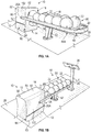
- Figs. 1A - IE show perspective views of a customizable bowling ball return assembly 10 according to principles of the present disclosure.
- the customizable bowling ball return assembly 10 generally can include a housing or housing portion 14 having a throat or discharge 16; and a bowling ball retrieval area 18 including at least one rail 20 and/or other suitable supports 48 for supporting a series of bowling balls 22 within the defined retrieval area 18.
- the bowling ball return assembly 10 can include a return mechanism 24 for returning bowling balls to the retrieval area 18.
- the bowling ball return assembly 10 also can include at least one control interface 26 operable to allow for control of operations at one or more bowling lanes of the bowling center 50 also can be provided, as indicated in Fig. 1C .
- Fig. 2 shows an exemplary ball return mechanism 24 according to one example of the present disclosure.
- the return mechanism 24 can include any suitable device that is operable to return bowling balls 22 to the retrieval area 18 for retrieval by a bowler without departing from the scope of the present disclosure.
- the return mechanism 24 can be recessed into the bowling alley floor 28, with a base plate 30 supporting the bottom portion 32 of the return mechanism 24 below the floor 28 of the bowling center, and a lane plate 34 generally supporting a middle portion 36 of the return mechanism 24 on or above the alley floor 28.
- Bowling balls 22 generally will enter at the bottom 32 of the return mechanism 24, which will lift the bowling balls 22 towards and through the throat/discharge 16 of the housing 14 whereupon the bowling balls 22 can be received and collected along the retrieval area 18.
- the return mechanism 24 also can include a first set of guide rails 38 and an oppositely-oriented second set of guide rails 40 that guide the bowling ball 22 along an upward path 42 through the return mechanism 24.
- the return mechanism 24 further can include rotating wheels 44 or other driving mechanism(s) that can engage and move the bowling balls 22 along the path 42 defined by the guide rails 38/40.
- the wheels 44 can be driven by a drive motor 46, though other suitable drive mechanisms or actuators can be used, without departing from the scope of the present disclosure.
- Example return mechanisms are shown and described in U.S. Patent Application No. 14/684,736 , which is hereby incorporated by reference as if set forth in its entirety.
- the bowling ball return assembly of the present disclosure further can include a surface ball return assembly 200 as illustrated in the embodiments shown in Figs. 4A-5B (discussed below).
- the bowling balls 22 exit the return mechanism 24 through the throat 16 in the housing 14.
- the throat 16 generally will be sized to be larger than a standard bowling ball; however, the size of the throat 16 may be varied, including being significantly larger than the size of a standard bowling ball, which may be differently defined by private bowling organizations of leagues. For example, the Professional Bowlers Association in United States indicates that the standard size of a bowling ball has a circumference of no more than 27 inches and a weight in the range of 10 to 16 pounds. It will be recognized, however, that other organizations, leagues, etc. may establish other standard bowling ball sizes.
- the throat 16 further can be dimensioned, sized, or otherwise configured to accommodate duckpin, fire-pin, candlepin, etc., or other suitable bowling balls, without departing from the scope of the present disclosure.
- Figs. 1A-1E additionally show that the retrieval area 18 generally includes a rail 20 and at least one center support 48 that at least partially defines a track or racking area 50 that can receive and retain a series of bowling balls 22 after they have been returned by the return mechanism 24 for retrieval by a bowler.
- the rail 20 can define a substantially arcuate, U-shaped, or otherwise shaped member having end portions 20A and 20B that are coupled to the housing 14 and/or customizable sections/portions 12. While the rail 20 is shown as generally U-shaped, the rail 20 can include any suitable shape and/or configuration, without departing from the scope of the present disclosure.
- At least a portion of the rail 20 further can be connected to the center support 48 of the retrieval area, on which the bowling balls are received.
- at least one post, column or other suitable support 52 can be provided to at least partially support the center support 48, and the rail 20 coupled thereto above the alley floor 28, as indicated in Figs. 1A-1D .
- the post 52 can be coupled to a lower surface 48A of the center support 48, and to the floor 28 of the bowling center, e.g., by one or more fasteners or other suitable fixing or attachment mechanisms.
- Figs. 3A, 3B show example housings 14 for the customizable bowling ball return assembly 10.
- the housing 14 can have a body 60 that can be engaged with the plate 34 and/or the bowling center floor 28.
- the housing body 60 can have a front 62, rear 64, side 66 and 68, top 70, and/or a bottom 72 parts that together at least partially surround and protect the internal components of the return mechanism 24 from damage, or from being accessed by bowlers.
- the configuration of the housing body 60 also can be structured to restrict access internally thereto, to try to minimize physical injuries to bowlers, for example, bowlers that intentionally or unintentionally reach into the moving components of the return mechanism.
- the housing 14 can include front and rear portions or plates with at least one of the customizable portion/sections 12 provided therebetween.
- Figs. 4A and 4B show a customizable bowling ball assembly 200 according to alternative/additional principles of the present disclosure.
- the bowling ball return assembly 200 is constructed/configured as a surface ball return assembly.
- the bowling ball assembly 200 generally includes a housing 214 with a body 260 that rests on or otherwise engages the bowling center floor 28.
- the housing 214 further has a passage or opening 202 defined therethrough that allows for the passage of bowling balls 22 to a retrieval area 218.
- the bowling ball return assembly 200 has a track or path 204 that extends/guides bowling balls 22 through /along the housing 214 (e.g., through the passage/opening 202) and to the retrieval area 218.
- the track or path 204 can have a first portion/area 206 having a ramped or sloped shape/construction/configuration to guide the bowling balls up towards and through the housing 212, and a second portion/area 208 with a generally straight shape/construction/configuration that guides the bowling balls 22 through the housing 214 (e.g., through passage 202) and then the retrieval area 218.
- the track/path 204 can have one or more guide surfaces 204A with a curved or arcuate shape that is generally complementary to the outer surface of the bowling balls 22 and further is configured to engage/contact the bowling balls 22 as they move therealong.
- the track/path 204 further can include guides, rails or other protruding/extending portions 204B provided therealong.
- the guides 204B are configured to contact/engage the bowling balls 22 as they move along the track 204, e.g., to substantially reduce, prevent, or inhibit the bowling balls 22 from being displaced/dislodged from, such as by bouncing out of, etc. the track as they move therealong.
- the track 204 can be in communication with a similarly constructed track 250 that extends/travels along the bowling lane(s).
- the track 250 can have a slope or grade variant that causes the balls to move therealong, e.g., by force/acceleration of gravity, towards the bowling ball assembly 200.
- bowling balls 22 that are rolled down the lane can be loaded onto the track 250 by one or more lifting mechanisms (e.g., including a lift(s), rotating wheel(s), etc.) so that the balls then will travel down the track 250 towards the bowling ball return assembly 200 on to track 204 to be directed through the housing 214 and onto the retrieval area 218.
- the bowling ball return assembly 200, track 204, track 250, etc. can generally be sized, dimensioned, or configured for return of bowling balls of any size, type, etc., such as ten-pin balls, duckpin balls, five-pin balls, candlepin balls, etc.
- Fig. 4A further shows that the housing 214 can have an upper portion 252 that covers/extends over at least a portion of the track 204 (e.g., at least part of the second portion/area 208).
- the upper portion 252 can at least partially define an opening/discharge 254 that allows for passage of the bowling balls 22 onto the retrieval area 218.
- the upper portion 252 can be omitted, however, as shown in Fig. 4A , and the housing 214 can have an opening or aperture 256 or otherwise can be open along an upper or top portion thereof.
- the second portion 208 of the track 204 and bowling balls 22 moving therealong are generally visible to the bowlers/customers at the lane.
- the retrieval area 218 can have an elongated body, rail, support, etc. 258 with a track 262 defined therealong to support/hold the bowling balls 22, e.g., until they are retrieved by bowlers at the lane.
- the track 262 is in communication with track 204 for receiving the bowling balls 22 therefrom.
- the elongated body 258 can have a stop portion 264 at an end 250A thereof that is configured to engage/stop the bowling balls along the track 262 for holding in the retrieval area 218.
- the retrieval area 218 further can include a post, support, etc. 266 that supports the elongated body 258 on the floor 28.
- Figs. 1A-1E , 3A-3B and 4A-4B further show that the housing 14, 214 can include one or more customizable, interchangeable sections or portions 12, 212 that can be selectively coupled to and/or can form or define the various parts of the housing body 60, 260 (e.g., between rear and forward portions of the housing body 60).
- the customizable, interchangeable sections or portions 12, 212 generally will include at least one surface or face 80, 280 with one or more colors, designs, graphics, textures, etc., for example, that can be selected by a user.
- Table 1 provides example colors or designs for the at least one surface or face 80, 280.
- the customizable, interchangeable sections or portions 12, 212 further can be readily attached to and detached from the housing body 60, 260 to allow the housing body 60, 260 to be customized, for example, to match one or more themes, designs, etc. of the bowling center.
- TABLE 1 Color Name SKU Evo Shell 537906 Shantung Amber 537540 Weathered Shingle Grey 537923 Horizon Mist 537916 Baha Oasis 537981 Cerused Graphite 537798 Warehouse Painted Plank 538022 Warehouse Worn Plank 538119 Horizon Cloud 537917
- Figs. 3A, 3B , 4A and 4B further show that the one or more customizable, interchangeable sections or portions 12, 212 can be sized, shaped, or otherwise configured to make up, conform, or be complementary to and at least partially cover or be apart of the exterior surface 60A, 260A of the housing body 60, 260.
- the customizable, interchangeable sections/portions 12 can include at least one top section/portion 82 that is complementary to the top part 70 and at least one of the side parts 66/68 of the housing body 60.
- top section or portion 82 can be generally U-shaped or have a generally saddle-like shape, with an upper part 84 that at least partially covers an exterior surface 70A of the top part 70 of the housing body 60, and a pair of opposing side parts 86/88 that are generally perpendicular or otherwise transverse to the upper part 84 and at least partially cover the exterior surfaces 66A and 68A of the side parts 66/68 of the housing body 60.
- the customizable, interchangeable sections or portions 12 additionally can include one or more sections or portions 90 that have a generally rectangular or other shape, and which are configured to cover at least some of the exterior surface(s) 66A/66B of side portions 66/68, for example, at, near, or substantially adjacent to a bottom end 66B/68B thereof.
- the one or more customizable portions 12 can include a single, unitary section/portion 13 sized, shaped, or otherwise configured to conform or be complementary to and at least partially cover the exterior surface 60A of the housing body 60.
- the unitary section/portion 13 can be generally U-shaped or have a generally saddle-like shape, with an upper portion or section 85 that extends along and substantially covers an exterior surface 70A of the top part 70 of the housing body 60, and a pair of opposing side parts 87/89 extending from the upper portion 85 generally perpendicular or otherwise transverse thereto and substantially covering the exterior surfaces 66A and 68A of the side parts 66/68 of the housing body 60.
- the unitary section/portion 13 can include additional customizable portions 12 attached thereto (e.g., disposed on an outer surface thereof) to provide further customization opportunities.
- the customizable, interchangeable, modular sections or portions 212 can include a pair of sections or portions 212 positioned on/along opposing sides of the housing body 60.
- the sections or portions 212 are shown as being generally parallel to each other, though the sections/portions 212 can be transverse in relation to one another, e.g., can be slanted, angled, etc., without departing from the scope of the present disclosure.
- the sections/portions 212 can have a generally flat shape or construction, further can comprise various shapes, such as rectangles, triangles, arcuate shapes/portions etc., though other shapes, such as circles, ovals, polygons, etc., are possible without departing from the scope of the present disclosure.
- the sections/portions 212 can include a first, upper portion 212A extending along the second portion 208 of the track 204, and a second, lower portion 212B extending from the first, upper portion 212A to a bottom portion 260B of the housing body 260, e.g., extending to a position substantially abutting or substantially adjacent to the floor 28.
- the customizable, interchangeable, modular sections or portions 212 can include additional customizable portions 12 attached thereto (e.g., disposed on an outer surface thereof) to provide further customization opportunities.
- any suitable number of customizable, interchangeable, modular sections/portions 12, 212, with any suitable shapes, e.g., circular, oval, square, triangular, polygonal, etc. or combinations thereof, and any suitable configurations or arrangements, can be provided/employed without departing from the scope of the present disclosure.
- the customizable, interchangeable sections/portions 12, 212 generally can be formed from a laminate material, such as a high-pressure laminate.
- the customizable, interchangeable sections 12, 212 can include at least one substrate or base layer 150 that can be formed of plywood, fiber board, or other composite or layered/paneled materials, with a décor or design layer 152 disposed/received thereon ( Fig. 3B , 4A , 4B , 5 ).
- the design or decor layer 152 can include a laminate sheet material, such as a plastic material, a paper material or other similar material layer (or series of stacked layers) having one or more colors, images, textures, finishes, etc. that can be selected by a customer to provide a customizable look/aesthetic to the housing body.
- the decor layer 152 also can include photo luminescent inks, reactive inks, etc., without departing from the scope of the present disclosure, and in some constructions, the décor layer 152 can include inks, dyes, etc. that are configured to provide the appearance of one or more three-dimensional images.
- the substrate layer 150 can be formed and selectively shaped, e.g., bent, cut, trimmed, etc., to generally conform to at least one selected part of the housing body 60. Thereafter, the décor layer 152 can be applied/laminated to the substrate layer to provide the customer selected appearance texture, finish, etc. thereto, and likewise the portion of the housing to which it is connected. However, the décor layer 152 can be applied over the substrate layer 150 prior to its shaping without departing from the scope of the present disclosure.
- Fig. 5 shows a cross sectional view of the customizable sections/portions 12, 212 coupled to the housing body 60, 260 according to one example of the present disclosure.
- the décor layer 152 e.g., including a laminate sheet material
- the substrate layer 150 e.g., including plywood, fiber board, or other composite or layered/paneled materials.
- the décor layer 152 includes the selected/customized colors, images, finishes, textures, etc. provided on its outward facing surface 152A.
- the décor layer 152 and the substrate layer 150 further can be coupled together by a reliable attachment, such as an adhesive, glue, etc.
- the substrate layer 150 also can be coupled/attached to the outer surface 60A, 260A of the housing body 60, 260 (e.g., including polymeric materials, such as plastics, elastomers, etc., or other suitable materials, such as metals or other composite or synthetic materials) by one or more adhesive layers 154, such as adhesive tape, glue, epoxy, etc. Additionally, or in alternative constructions, there will be no adhesive layer 154 and the surface 150B can be in face to face contact with or otherwise abut the surface 60A, 260A of the housing body 60, 260, with the customizable portions/sections 12, 212 being secured in place with fasteners, such as bolts, screws, etc., such as in connection assembly 300 shown in Fig.
- a latch, or pinned connection, etc. that facilitate relatively quick or easy removal of the substrate layer 150 from the housing 60, 260, and further can enable multiple attachments and removals, without substantial damage to the substrate layer and/or the housing, while also providing a substantially tight, secure connection/attachment between the substrate layer 150 and the housing body 60, 260, e.g., substantially preventing, reducing, or inhibiting displacement, dislodging, disconnection, dislocation, etc. of the customizable sections/portions from the housing during use of the return mechanism, such as due to vibrations, impacts, etc. at the bowling lane.
- FIG. 5 Although only one customizable portions/sections 12, 212 is shown in Fig. 5 , multiple (e.g., two or more) customizable portions/sections 12, 212 can be provided, such as two or more customizable portions/sections 12, 212 superposed over each other to provide for additional customization options, without departing from the scope of the present disclosure.
- the customizable, interchangeable sections or portions 12, 212 can be releasably coupled or otherwise fixed to the housing body 60 using any suitable mechanism or means, such as adhesives, snap-fit and/or other mechanical connections, etc., without departing from the scope of the present disclosure.
- the customizable, interchangeable sections or portions 12 can be at least partially received within one or more complementary grooves, cavities, or recessed portions 92/94 defined in/along the housing body 60, with one or more of such customizable, interchangeable portions ( i.e., portion 82 as shown in Fig. 1B ) slidably or snap-fitted within a groove 92 defined along the top and/or side parts 66/68 of the housing body.
- customizable, interchangeable portions i.e., part 90
- portions 82 and 90 can be substantially easily and relatively quickly attached and detached to the housing body 60.
- the customizable sections or portions 12 further can be coupled to each other and/or the housing body 60 using one or more fastening mechanism, connecting members, fasteners, adhesives, etc., without departing from the scope of the present disclosure.
- the return assembly 10 can include connecting or accent members 98 for coupling the sections/portions 12 together and/or to the housing body 60.
- the connections members 98 can include an elongated body 100 having slots or grooves 102/104 defined therealong, that are sized and/or configured to receive an end portion 106/108 of at least one of the customizable, interchangeable portions/sections 12.
- the body 100 can be formed from a metallic material, such as stainless steel, aluminum, etc., or other suitable material, such as plastic, rubber, wood, etc.
- the connecting members 98 can be positioned about the side parts of the housing body 60 and can connect the ends of sections 82 and 90.
- the ends 106/108 of the sections 82 and 90 can be slidably fit and frictionally engage within the grooves 102/104 to couple sections 82/90 together.
- the connecting member(s) 98 further can have one or more fasteners 110, such as screws, bolts, rivets, etc., for attaching the sections 12 thereto as shown in Fig. 7B .
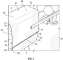
- Fig. 8 further shows that the connecting or accent member(s) 98 can be configured to be adhered or bonded to at least one of the customizable sections 12.
- the connecting members 98 can have a bonding surface 112 that at least partially receives adhesive 114 to secure the connecting member 98 to at least a portion of the customizable/interchangeable sections 12.
- the adhesive 114 can include a double sided adhesive tape that can be attached or affixed to the bonding surface 114.
- the double sided adhesive tape can include double sided adhesive acrylic tapes, vinyl tapes, etc.
- the customizable bowling ball return mechanism 10 also can include a series of light sources 120, such as LEDs, light bulbs, etc. disposed therealong ( Figs. 7A and 7B ).
- Such light sources 120 can be arranged along the connecting members 98 or a portion of the customizable sections 12 or housing body 60 substantially adjacent the connecting members 98.
- the connecting members 98 can have a flange 122 or other projecting portion that can at least partially cover the light sources 120 ( Figs. 7A and 7B ), and the light sources 120 further can be positioned to illuminate at least a portion of the housing body 60, the customizable section 12, and/or an area adjacent the assembly 10.
- the light sources 120 can be positioned to at least partially reflect light off the flange 122 such that a portion 124 of the floor 28 substantially adjacent the housing 14 is illuminated.
- the light sources can be arranged along any portion of the assembly 10, e.g., the rails, support, inside the throat, etc., without departing from the scope of the present disclosure.
- the customizable sections 12 or housing body 60 additionally can have one or more translucent sections 126 that can be selectively illuminated by various ones of the light source(s) to provide various other visual effects.
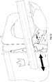
- Figs. 6 , 9A and 9B show that the assembly 10 generally will have one or more end caps 130 that at least partially cover an end portion 132 of the connecting member 98, for example, to prevent injury to a bowler that may touch or bump into the connecting member 98.
- the end caps 130 can have an opening 134 that receives the end portions 132 of the connecting member 98 ( Fig. 9B ).
- the end caps 130 also can have a groove or slot 136 that receives at least a portion of the customizable sections 12.
- Fig. 10 shows a connection assembly 300 for attachment of the customizable sections/portions 12 to the housing/housing portion(s) 14 according to one example of the present disclosure.
- the connection assembly 300 can include a plurality of brackets 302, 304 including one or more brackets 302 connected to the customizable portion/section 12 and one or more brackets 304 connected to the housing portion 14 and/or portions of the rail 20.
- the brackets 302, 304 further may have one or more holes, aperatures, etc.
- brackets 304/306 can include a space series of holes/apertures to facilitate adjustment of the connection assembly 300.
- Embodiments of the present disclosure also can provide a method or process for customer/user design or customization of a bowling ball return assembly. For example, in some variations, prior to purchasing the return assembly, customers can access a website, mobile application, etc., and design and customize colors, images, finishes, textures, etc. for each of the plurality of customizable, interchangeable sections 12, 212, e.g., design data or information can be received from customers and used to develop custom designs.
- the selected colors, finishes, images, textures, etc. can be provided (e.g., printed, painted, etc.) on the décor layer 152.
- the décor layer 152 then can be applied to/over the substrate layer 150 of the customizable, interchangeable section 12, 212.
- the entire customizable, interchangeable section 12, 212, including the substrate 150 and décor layer 152, can be formed, shaped, etc. to correspond to or at least partially cover at least a portion of the housing 60, 260 of the bowling ball return assembly, though the substrate layer 150 can be formed, shaped, etc. to at least partially cover/correspond to selected portion or portions of the housing 60, 260 prior to the application of the décor layer 152 thereto.
- the customizable, interchangeable sections 12, 212, with the customized design provide thereon, can be attached, coupled, etc. to the housing 14, 214 of the return assembly.
- a fasteners, brackets, and/or or other suitable connections mechanisms can be to couple to the sections 12, 212 the body 60, 260 of the housing 14, 214, although other reliable connector, such as adhesives, latching mechanisms, etc. can be used without departing from the scope of the present disclosure.
- a customer wants to later change/modify the design, e.g., to match updates to a bowling center, the customer can access the website, mobile application, etc. and design new customizable, interchangeable sections to replace the existing section 12, 212 to alter the design and look of the housing.
- a customer could purchase a kit with differently designed sections 12, 212 that can be easily interchangeable, for example, to correspond to specific themes, seasons, holidays, etc.
Landscapes
- Casings For Electric Apparatus (AREA)
- Toys (AREA)
Abstract
Description
- The present application claims the benefit of
U.S. Provisional Patent Application No. 62/660,483, which was filed April 20, 2018 -
U.S. Provisional Patent Application No. 62/660,483, which was filed April 20, 2018 - The present disclosure relates to bowling, and in particular, mechanisms, systems, or assemblies for returning bowling balls to bowlers.
- Bowling ball returns are generally among the most highly visible parts of a bowling center's interior design. Existing bowling ball returns, however, traditionally have been offered only in a limited number of configurations, colors, designs, etc. Manufacturers typically standardize the manufactured design and color options for ball returns to minimize manufacturing inconsistencies, setup and inventory costs, etc. In addition, the housing and/or other components of typical bowling ball returns often are formed by injection molding techniques, with the manufacturer's signature color generally injected during the molding process or by painting the formed housing/components before assembly. As a result, if a customer wants a unique or custom color for their bowling ball return or wants to change/customize the design of the bowling ball return, the manufacturer usually must paint the housing or other components of the bowling ball return and/or pass any further costs of such customization to the customer. Such a process also generally does not allow for specific images, textures, finishes, etc. to be customizably incorporated within the housing or other components of the bowling ball return, particularly after installation of the bowling ball return. Accordingly, it can be seen that a need exists for customizable bowling ball return assembly that addresses the foregoing and other related, and unrelated, issues/problems in the art.
- Briefly described, the present disclosure provides a customizable bowling ball return assembly. The customizable bowling ball return assembly can include a housing or housing portion that is positioned adjacent to a retrieval area that receives bowling balls for retrieval by bowlers at a lane or lanes. The housing can include a passage or discharge defined therein that is sized, dimensioned, or configured to allow for passage of the one or more bowling balls to the retrieval area.
- The bowling ball return assembly further can comprise one or more customizable, modular, or interchangeable portions of a selected size, dimension, shape, or configuration that are configured to be selectively coupled to the housing. The one or more customizable, modular, or interchangeable portions can include a surface or face with one or more selected colors, images, depictions, graphics, themes, finishes, textures, or combinations thereof provided on the surface or face.
- In some embodiments, the bowling ball return assembly can include an automated return mechanism that is operable to direct bowling balls to a retrieval area. The housing can at least partially enclose or surround the return mechanism. The return mechanism can include a plurality of belts, rotating wheels, or other drive mechanisms that move and/or guide the returned bowling balls along at least one set of guide rails towards and through a passage/throat in the housing for discharge of the balls onto the one or more supports and/or rails of the retrieval area.
- In alternative constructions/variations, the bowling ball return assembly can include a surface return assembly, and the housing can include a passage with a track or path defined therethrough that allows for passage of bowling balls from a track or guide area provided along the bowling lanes through the housing and to the retrieval area.
- The retrieval area can include an elongated body configured to receive and support a plurality of bowling balls, and in some embodiments, can have one or more supports and/or rails that at least partially support the returned bowling balls for retrieval by a bowler(s). Alternatively, the elongated body of the retrieval area can have a track/guide surface that receives/supports the bowling balls.
- The one or more customizable, modular, and/or interchangeable sections or portions that can have various sizes, dimensions, shapes, configurations, etc. and can be selectively configurable and selectively coupled to the housing of the bowling ball return assembly. The customizable sections/portions also can include one or more colors, images, depictions, graphics, themes, finishes, textures, etc., or combinations thereof.
- In some embodiments, each of the sections or portions can include one or more selected colors, graphics, textures, finishes, etc. that can be selected by a customer, for example, to correspond to a theme or otherwise match the interior design of the customer's bowling center.
- The customizable sections/portions further can be formed from a high-pressure laminate material. In one example, the customizable sections/portions can include a substrate layer, e.g., formed from a plywood, a fiberboard material, etc. or other composite materials that is formed into the customizable section shape, and a design or décor layer, including a laminate sheet material, plastic material, or paper material received/applied over the substrate layer. The design layer can include one or more colors, graphics, pictures, images, textures, finishes, etc., e.g., which can be selected by a customer/user to customize the bowling ball return assembly.
- The bowling ball return assembly further can include one or more connecting mechanisms, such as fasteners, adhesives, snap-fitted connections, etc., that are configured to releasably couple the customizable sections/portions together and/or to at least part of the housing. The sections/portions of the bowling ball return assembly thus can be made to be interchangeable to enable further customization as needed or desired.
- In some embodiments, one or more adhesives, such as double-sided adhesive tape or other suitable adhesives, can be applied to the customizable sections/portions and/or the housing of the bowling ball return assembly to couple the customizable sections/portions together and/or to the housing.
- Additionally, or in alternative constructions, the bowling ball return assembly further can include one or more connecting members or portions that releasably couple to the customizable sections/portions together and/or to at least a portion of the housing. In one example, the connecting members can have an elongated body with one or more grooves or slots defined therein that receive at least a portion, e.g., an end portion, of the customizable sections/portions to secure the customizable portions thereto, e.g., in slidable frictional engagement.
- In further additional or alternative constructions, one or more fasteners can be used to secure at least a portion of the customizable sections/portions to the connecting members and/or to the housing.
- The customizable bowling ball return assembly further can include one or more light sources, LEDs, etc., arranged therealong. For example, the one or more light sources can be positioned along the connecting members to illuminate portions of the bowling ball return assembly or an area adjacent thereto. The light sources can be positioned along any suitable portion of the bowling ball return assembly, however, without departing from the scope of the present disclosure.
- The housing and/or one or more of the plurality of customizable, interchangeable sections/portions also can have one or more translucent portions or areas. These translucent portions or areas can be used to provide additional visual effects. For example, such translucent portions or areas further can be illuminated by one or more light sources.
- Those skilled in the art will appreciate the above stated advantages and other advantages and benefits of various additional embodiments by reading the following detailed description of the embodiments with reference to the below listed drawing figures.
- The accompanying drawings, which are included to provide a further understanding of the embodiments of the present disclosure, are incorporated in and constitute a part of this specification, illustrate embodiments of the present disclosure, and together with the detailed description, serve to explain the principles of the embodiments discussed herein. No attempt is made to show structural details of this disclosure in more detail than may be necessary for a fundamental understanding of the exemplary embodiments discussed herein and the various ways in which they may be practiced. According to common practice, the various features of the drawings discussed below are not necessarily drawn to scale. Dimensions of various features and elements in the drawings may be expanded or reduced to more clearly illustrate the embodiments of the disclosure.
-
Figs. 1A - 1E show perspective views of a bowling ball return assembly according to principles of the present disclosure. -
Fig. 2 shows an example bowling ball return mechanism according to one example of the present disclosure. -
Figs. 3A - 3B show perspective views of a housing of the bowling ball return assembly according toFigs. 1A-1C . -
Figs. 4A - 4B show perspective views of a bowling ball return assembly according to additional principles of the present disclosure. -
Fig. 5 shows a cross sectional view of the customizable sections/portions and the housing according to one example of the present disclosure. -
Fig. 6 shows a perspective view of the assembly with a connecting member according to principles of the present disclosure. -
Fig. 7A and 7B show cross-sectional views of connecting members according to principles of the disclosure. -
Fig. 8 shows cross-sectional and perspective views of a connecting member according to yet another example of the present disclosure. -
Figs. 9A - 9B show perspective views of example end caps for the connecting members according to principles of the present disclosure. -
Fig. 10 shows a connection mechanism for attachment of the customizable sections/portions according to one example of the present disclosure. -
Figs. 1A-10 generally illustrate various example embodiments of a customizable bowlingball return assembly ball return assembly customizable sections various sections ball return assembly - As further will be understood, the following description is provided as an enabling teaching of embodiments of this disclosure. Those skilled in the relevant art will recognize that many changes can be made to the embodiments described, while still obtaining the beneficial or desired results. It will also be apparent that some of the desired benefits of the embodiments described can be obtained by selecting some of the features of the embodiments without utilizing other features. Accordingly, those who work in the art will recognize that many modifications and adaptations to the embodiments described are possible and may even be desirable in certain circumstances. Thus, the following description is provided as illustrative of the principles of the embodiments of a customizable bowling ball return assembly and not in limitation thereof.
-
Figs. 1A - IE show perspective views of a customizable bowlingball return assembly 10 according to principles of the present disclosure. As shown inFigs. 1A - IE, the customizable bowlingball return assembly 10 generally can include a housing orhousing portion 14 having a throat ordischarge 16; and a bowlingball retrieval area 18 including at least onerail 20 and/or othersuitable supports 48 for supporting a series ofbowling balls 22 within the definedretrieval area 18. In some embodiments, as shown inFig. 2 , the bowlingball return assembly 10 can include areturn mechanism 24 for returning bowling balls to theretrieval area 18. The bowlingball return assembly 10 also can include at least onecontrol interface 26 operable to allow for control of operations at one or more bowling lanes of thebowling center 50 also can be provided, as indicated inFig. 1C . -
Fig. 2 shows an exemplaryball return mechanism 24 according to one example of the present disclosure. Thereturn mechanism 24 can include any suitable device that is operable to returnbowling balls 22 to theretrieval area 18 for retrieval by a bowler without departing from the scope of the present disclosure. For example, as generally illustrated inFig. 2 , thereturn mechanism 24 can be recessed into thebowling alley floor 28, with abase plate 30 supporting thebottom portion 32 of thereturn mechanism 24 below thefloor 28 of the bowling center, and alane plate 34 generally supporting amiddle portion 36 of thereturn mechanism 24 on or above thealley floor 28. Bowlingballs 22 generally will enter at the bottom 32 of thereturn mechanism 24, which will lift thebowling balls 22 towards and through the throat/discharge 16 of thehousing 14 whereupon thebowling balls 22 can be received and collected along theretrieval area 18. In one embodiment, thereturn mechanism 24 also can include a first set ofguide rails 38 and an oppositely-oriented second set ofguide rails 40 that guide thebowling ball 22 along anupward path 42 through thereturn mechanism 24. Thereturn mechanism 24 further can includerotating wheels 44 or other driving mechanism(s) that can engage and move thebowling balls 22 along thepath 42 defined by the guide rails 38/40. Thewheels 44 can be driven by adrive motor 46, though other suitable drive mechanisms or actuators can be used, without departing from the scope of the present disclosure. - It will be recognized, however, that other types of return mechanisms and/or bowling ball lifts may be used to move the
bowling balls 22 to theretrieval area 18 without departing from the scope of the present disclosure. This could include moving/returning the bowling balls to the retrieval area by elevator lifts, kinetic energy machines, vacuum lift tubes, etc. or any other suitable devices, mechanisms, etc. It further will be recognized that the operation of the drive motor or other components of the return mechanism may be in continuous operation or non-continuous operation, i.e., the motor or other components of the return mechanism are only operated when a bowling ball enters the bottom of the return mechanism and is moved therethrough, such that once the bowling ball has moved through and released from the return mechanism, the drive motor or other components of the return mechanism can be shut off. Example return mechanisms are shown and described inU.S. Patent Application No. 14/684,736 , which is hereby incorporated by reference as if set forth in its entirety. The bowling ball return assembly of the present disclosure further can include a surface ball return assembly 200 as illustrated in the embodiments shown inFigs. 4A-5B (discussed below). - As also shown in
Figs. 1A-1E , thebowling balls 22 exit thereturn mechanism 24 through thethroat 16 in thehousing 14. Thethroat 16 generally will be sized to be larger than a standard bowling ball; however, the size of thethroat 16 may be varied, including being significantly larger than the size of a standard bowling ball, which may be differently defined by private bowling organizations of leagues. For example, the Professional Bowlers Association in United States indicates that the standard size of a bowling ball has a circumference of no more than 27 inches and a weight in the range of 10 to 16 pounds. It will be recognized, however, that other organizations, leagues, etc. may establish other standard bowling ball sizes. Thethroat 16 further can be dimensioned, sized, or otherwise configured to accommodate duckpin, fire-pin, candlepin, etc., or other suitable bowling balls, without departing from the scope of the present disclosure. -
Figs. 1A-1E additionally show that theretrieval area 18 generally includes arail 20 and at least onecenter support 48 that at least partially defines a track or rackingarea 50 that can receive and retain a series ofbowling balls 22 after they have been returned by thereturn mechanism 24 for retrieval by a bowler. Therail 20 can define a substantially arcuate, U-shaped, or otherwise shaped member havingend portions housing 14 and/or customizable sections/portions 12. While therail 20 is shown as generally U-shaped, therail 20 can include any suitable shape and/or configuration, without departing from the scope of the present disclosure. - At least a portion of the
rail 20 further can be connected to thecenter support 48 of the retrieval area, on which the bowling balls are received. In addition, at least one post, column or othersuitable support 52 can be provided to at least partially support thecenter support 48, and therail 20 coupled thereto above thealley floor 28, as indicated inFigs. 1A-1D . Thepost 52 can be coupled to alower surface 48A of thecenter support 48, and to thefloor 28 of the bowling center, e.g., by one or more fasteners or other suitable fixing or attachment mechanisms. -
Figs. 3A, 3B show example housings 14 for the customizable bowlingball return assembly 10. As shown inFigs. 3A, 3B , thehousing 14 can have abody 60 that can be engaged with theplate 34 and/or thebowling center floor 28. Thehousing body 60 can have a front 62, rear 64,side return mechanism 24 from damage, or from being accessed by bowlers. The configuration of thehousing body 60 also can be structured to restrict access internally thereto, to try to minimize physical injuries to bowlers, for example, bowlers that intentionally or unintentionally reach into the moving components of the return mechanism. In some embodiments, thehousing 14 can include front and rear portions or plates with at least one of the customizable portion/sections 12 provided therebetween. -
Figs. 4A and4B show a customizablebowling ball assembly 200 according to alternative/additional principles of the present disclosure. The bowlingball return assembly 200 is constructed/configured as a surface ball return assembly. As shown inFigs. 4A and4B , thebowling ball assembly 200 generally includes ahousing 214 with abody 260 that rests on or otherwise engages thebowling center floor 28. Thehousing 214 further has a passage oropening 202 defined therethrough that allows for the passage ofbowling balls 22 to aretrieval area 218. - As shown in the embodiments illustrated in
Figs. 4A and4B , the bowlingball return assembly 200 has a track orpath 204 that extends/guidesbowling balls 22 through /along the housing 214 (e.g., through the passage/opening 202) and to theretrieval area 218. The track orpath 204 can have a first portion/area 206 having a ramped or sloped shape/construction/configuration to guide the bowling balls up towards and through thehousing 212, and a second portion/area 208 with a generally straight shape/construction/configuration that guides thebowling balls 22 through the housing 214 (e.g., through passage 202) and then theretrieval area 218. The track/path 204 can have one ormore guide surfaces 204A with a curved or arcuate shape that is generally complementary to the outer surface of thebowling balls 22 and further is configured to engage/contact thebowling balls 22 as they move therealong. - The track/
path 204 further can include guides, rails or other protruding/extendingportions 204B provided therealong. Theguides 204B are configured to contact/engage thebowling balls 22 as they move along thetrack 204, e.g., to substantially reduce, prevent, or inhibit thebowling balls 22 from being displaced/dislodged from, such as by bouncing out of, etc. the track as they move therealong. Thetrack 204 can be in communication with a similarly constructedtrack 250 that extends/travels along the bowling lane(s). Thetrack 250 can have a slope or grade variant that causes the balls to move therealong, e.g., by force/acceleration of gravity, towards thebowling ball assembly 200. - In one example,
bowling balls 22 that are rolled down the lane (e.g., to strike pins, in the gutter, etc.) can be loaded onto thetrack 250 by one or more lifting mechanisms (e.g., including a lift(s), rotating wheel(s), etc.) so that the balls then will travel down thetrack 250 towards the bowling ball return assembly 200 on to track 204 to be directed through thehousing 214 and onto theretrieval area 218. The bowlingball return assembly 200,track 204,track 250, etc. can generally be sized, dimensioned, or configured for return of bowling balls of any size, type, etc., such as ten-pin balls, duckpin balls, five-pin balls, candlepin balls, etc. -
Fig. 4A further shows that thehousing 214 can have anupper portion 252 that covers/extends over at least a portion of the track 204 (e.g., at least part of the second portion/area 208). Theupper portion 252 can at least partially define an opening/discharge 254 that allows for passage of thebowling balls 22 onto theretrieval area 218. Theupper portion 252 can be omitted, however, as shown inFig. 4A , and thehousing 214 can have an opening oraperture 256 or otherwise can be open along an upper or top portion thereof. As a result, thesecond portion 208 of thetrack 204 andbowling balls 22 moving therealong are generally visible to the bowlers/customers at the lane. - As additionally shown in
Figs. 4A and4B , theretrieval area 218 can have an elongated body, rail, support, etc. 258 with atrack 262 defined therealong to support/hold thebowling balls 22, e.g., until they are retrieved by bowlers at the lane. Thetrack 262 is in communication withtrack 204 for receiving thebowling balls 22 therefrom. Theelongated body 258 can have astop portion 264 at anend 250A thereof that is configured to engage/stop the bowling balls along thetrack 262 for holding in theretrieval area 218. Theretrieval area 218 further can include a post, support, etc. 266 that supports theelongated body 258 on thefloor 28. -
Figs. 1A-1E ,3A-3B and4A-4B further show that thehousing portions housing body 60, 260 (e.g., between rear and forward portions of the housing body 60). The customizable, interchangeable sections orportions face face portions housing body housing body TABLE 1 Color Name SKU Evo Shell 537906 Shantung Amber 537540 Weathered Shingle Grey 537923 Horizon Mist 537916 Baha Oasis 537981 Cerused Graphite 537798 Warehouse Painted Plank 538022 Warehouse Worn Plank 538119 Horizon Cloud 537917 Evo Sol 537907 Baja Basin 537992 Shantung Oyster 537564 Shantung Gray 537541 Shantung Charcoal 537562 Michelangelo Graphite 537909 Michelangelo Chalk 537908 Shantung Pearl 537563 Providence Alabaster 537437 Providence Taupe 537439 Providence Slate 537453 Bodega Old Grey Plank 538434 Bodega Old Light Plank 538345 Providence Sable 537438 Mercury Noir 538438 Mercury Frost 538224 Mercury Cinder 538221 Providence Natural 537436 Providence Khaki 537454 Weathered Boardwalk 537924 Lenox Coco 537997 Lenox Rose Gold 538000 Lenox Smoke 538001 Lenox Wax 537998 Lenox Ash 537999 Tate Maple Light 538009 Oxford Slate Black 538282 Oxford Pearl 538292 Oxford Copper 538296 Oxford Brass 538298 Oxford Silver 538294 Oxford Mellow White 538284 Oxford Dark Iron 538286 Oxford Casual Taupe 538288 LampPost 527410 Market Oak Whitewashed 532473 Market Oak Gray 532472 Mackinac 530887 Constantia Mineral 536349 Constantia Graphite 536348 Constantia Earthen 536347 Craft Hickory Grey 536485 Stratus White 534136 Corten Metal 534274 Strada Sand 535351 Concrete Urban Grey 536288 Steel Diecast 527657 Concrete 527659 Tahoe Meadow 535362 Clove 508732 Studio White Dust 508642 City Lights 530146 Street Sign 527422 Concrete Stadium Gray 535872 Solara Oak 508667 Concrete Modern Ivory 536289 Shimmer 508959 Concrete Mixt Grey 535561 Shark Gray 509024 Flat Iron 527437 Shaker Cherry 521423 Fashion Grey 529010 Snowfall 535531 Venus Silver 508684 Global Oak Brown 536484 Valencia Granite Tuxedo 533850 Fusion Maple 508737 Smokehouse Oak 532474 Valencia Granite Evening 533876 Freedom Red 508772 Slate Grey 529346 Turino Fig 532385 Fantastico Sable 536882 Valencia Granite Champagne 533877 Tin Ceiling 527435 Ebony Starlight 508697 Turino Truffle 532386 Arturo Candlelight 534350 Crossfire Java 508746 Turino Porcini 532519 Antone Cerused Gray 534485 Craft Hickory Natural 536487 Avante Latte 534672 Fantastico Gilde 536871 Avante Kaffe 534673 Fantastico Blanco 536870 Auburn Pear 508648 Etched Medallion 526921 Cast-in-Bronze 530142 Arturo Moonlight 534351 Antone Cerused Carmel 534484 Tango Silk 536284 Amarelo Bronze 531922 Turino Espresso 532387 American Natural 508628 Caledonia Truffle 522147 Oxidized Pewter 534241 Platino Granite Tanin 533908 Cashmere 509018 Carrara 534372 Boothbay Pewter 536940 Boothbay Penny 536939 Bellini Platinum 536345 Matte Luxe Linen 537142 Matte Luxe Indigo 537340 Platino Granite Gray 533910 Matte Luxe Malachite 537339 Matte Luxe Folkstone 537349 Matte Luxe Charcoal 537348 Matte Luxe Caramel 537342 Obsidian Oak 512380 Matte Luxe Fade 537343 Matte Luxe Dove 537341 Matte Steele 527952 Romania Stone 529675 Matte Malachite 534460 Matte Succulent 534108 Saloma Alto 536632 Rift Oak Gray 534133 Matte Luxe Slate 537351 Plywood 533662 Matte Luxe Sage 537338 Matte Luxe Viridian 536731 Matte Luxe Teal 536743 Matte Luxe Bordeaux 536742 Indian Vyara Nobel 534655 Pompeii Marble Gray 533949 Laguna Pebble 508821 Jazz Silk 536285 Imperial Smoke 526928 Grande Walnut Grey 536991 Global Oak Natural 536483 Imperial Gold 526926 Tahoe Timber 535360 Almond Cherry 508837 Turino Almond 532384 Tunisia Stone 529661 Amarelo Silver 531923 Amarelo Gold 531924 Scandia Stone 529673 Palos Mahogany 512382 Calacutta Warm 536736 OMNOVA Frosty White 509997 Boothbay Sand 536938 Carbon Fibers Silver 508792 Bellini Pewter 536342 Bellini Bronze 536341 Avante Silver 537002 Blush Gold 536565 Platino Granite Sand 533900 Matte Luxe Gauntlet 537344 Matte Luxe Nautical 536388 Matte Luxe Malt 537350 OMNOVA Designer White 509996 Moderne Gold 536564 Metro Fresco 534522 Matte White 528683 Matte Luxe Cadet 537372 Matte Luxe Fashion 537115 Monterey Topaz 536631 Monterey Crystal 536630 River Cherry 508829 Matte Sage 534106 Rift Oak Natural 534135 Matte Sulfur 527932 Sandstone Natural 533914 Saloma Cirrus 536633 Matte Stone 527956 Matte Luxe White 536744 Pompeii Marble Espresso 533948 Pompeii Marble Creme 533947 Matte Luxe Shadow 537156 Rift Oak Brown 534134 Matte Luxe Succulent 537329 Red Oak 508749 Imperium Moonrise 534654 Imperium Highnoon 534696 Kings Pine Light 534938 Grande Walnut Natural 535270 Imperial Brown 526930 White 949 529621 Hayward Cherry 508626 Walnut Bella 521499 Matte Fade 534315 Matte Dove 534316 Vintage Marquee 527433 Fibers Concrete 508680 Matte Luxe Porcelain 537844 Matte Cadet 534103 Matte Luxe Black 536745 Matte Khaki 527958 Matte Indigo 534384 Matte Black 527960 Linea Blanca 534864 LeBelle Silk 536287 Pavement 53263 Stop 12232 Go-Go 32245 Goal Post 62514 Mascot 45647 Cheerleader 22249 Wedding Chapel 12235 3AM 42652 Wildcard 22252 The Chairman 42653 Appletini 32249 Railing 53235 Ticking 72946 Corduroy 72940 Linen 62518 Flax 72939 Seersucker 62515 Julep 32247 Sugarpuff 12236 Old Silver 42649 Shade 53234 Parasol 22250 Blue Bonnet 42656 Teacup 32242 Veranda 53262 Smoked 42651 Bayou 53260 Sponge Cake 12237 Cotton 62509 Porch 53233 Security 42654 Wicket 72938 Blotter 72959 Iron Safe 53216 Old Money 32248 Wax Seal 42655 Bank Note 22254 Cash Out 72944 Fraise 42648 Crema 32246 Downtown 12240 Emerald City 72937 After Dark 22253 Mostaza 32243 Ayers 32250 Ocean Requiem 42670 Riva 22257 Bolt 12238 Double York 72942 Current 72945 Path 62517 Brunt Toast 72943 Eiderdown 62516 Runway 72943 Cumulus 62516 Napoleon 42658 Cambridge 12234 Academy 32244 Heather 42650 Polo 32251 The Cape 72941 First Mate 42657 Oil Skin 72936 Black Watch 53259 Black Pearl 82542 Maudlin Pearl 82566 Zink 82539 Titanium 82543 Platinum 82544 Chrome 82546 Frosted Glass 82541 Tissue 82545 Chiffon 82619 Lace 82719 Doilie 82617 Vapour White 82620 Coppertex 82209 Case Brown 82717 Midas 82208 Sharpe 82308 Almond Gold 82714 Onyx 82715 Pearly 82713 Night Sky 82413 Reflection 82401 Sky Blue 82414 Mist 82415 Ritz 82411 Plush 82412 Pinot 82111 Shale 82540 Razzel 82112 Major 82728 Minor 82726 Footprint 82576 Shadow 82577 Moonstone 82421 Comets 82315 Galaxy 82478 Mars 82117 Half Tea 73012 Teacup 73015 Double Tea 73010 Woolblend 73011 Chino 73013 Cargo 73014 Poplin 53369 Gray Flannel 53370 Felt Gray 45711 Chess Partner 62537 Check Mate 53373 Vintage Leather 22268 Velvet 32264 Merlot 12256 Royal 42712 Eyecandy A0019 New Sails F0006 Transition E0015 Fresh C0002 Longbay D0008 First Call E0016 Achromatic E0014 Mystic D0009 Spinnaker A0018 Transformer 53429 Edge of Dreams 42732 Borrowed Light 53426 Voltage 53427 Time Warp 62562 Avatar 53428 Elevate 42731 Milky Way 62560 Silver Lining 62561 Slipper Satin 62563 All White 62564 Deep Space 42730 Sun Coral 82217 Cream 82721 Veruca 82420 Orange Peel 82216 Arsenic 82311 Transition 82312 Pale Green 82314 Pinke 82114 Face Value 82418 Arctic Blue 82419 Yello 82213 Steel Green 82310 Ohrange 82212 Red It 82113 Element 82309 Ribbon Blue 82416 Metabraun 82719 Billet 82551 Mita 82210 Coppertech 82211 Light Gold 82214 Broken Metal 82559 Frost Blue 82417 Fresno 82215 Coniferus 82313 Bobtail 82722 Chiffon Lite 82622 New Lace 82723 Silver Down 82556 Frost 82560 Metal 82558 Grate Gray 82557 Silver 82507 Copper 82103 Bronze 82704 Pearl 82606 Ductile Gold 82202 Strawberry Pop 82108 Lemon Star 82206 Shimmering Forest 82305 Olympic Cast 82406 Royal Grab 87407 Tundra Birch -- Manitoba Maple -- Fusion X -- Ellmau Beech -- Riga Birch -- Honey Maple -- Red Alder -- Pearwood -- Rustic Cherry -- Summerflame -- Shaker Cherry -- Chocolate Pear -- -
Figs. 3A, 3B ,4A and4B further show that the one or more customizable, interchangeable sections orportions exterior surface housing body Figs. 3A and 3B , the customizable, interchangeable sections/portions 12 can include at least one top section/portion 82 that is complementary to thetop part 70 and at least one of theside parts 66/68 of thehousing body 60.Figs. 3A-3B further show such a top section orportion 82 can be generally U-shaped or have a generally saddle-like shape, with anupper part 84 that at least partially covers anexterior surface 70A of thetop part 70 of thehousing body 60, and a pair of opposingside parts 86/88 that are generally perpendicular or otherwise transverse to theupper part 84 and at least partially cover theexterior surfaces side parts 66/68 of thehousing body 60. The customizable, interchangeable sections orportions 12 additionally can include one or more sections orportions 90 that have a generally rectangular or other shape, and which are configured to cover at least some of the exterior surface(s) 66A/66B ofside portions 66/68, for example, at, near, or substantially adjacent to abottom end 66B/68B thereof. - Also, as shown in
Fig. 1E , the one or morecustomizable portions 12 can include a single, unitary section/portion 13 sized, shaped, or otherwise configured to conform or be complementary to and at least partially cover theexterior surface 60A of thehousing body 60. In one embodiment, the unitary section/portion 13 can be generally U-shaped or have a generally saddle-like shape, with an upper portion orsection 85 that extends along and substantially covers anexterior surface 70A of thetop part 70 of thehousing body 60, and a pair of opposingside parts 87/89 extending from theupper portion 85 generally perpendicular or otherwise transverse thereto and substantially covering theexterior surfaces side parts 66/68 of thehousing body 60. In additional, or alternative constructions, the unitary section/portion 13 can include additionalcustomizable portions 12 attached thereto (e.g., disposed on an outer surface thereof) to provide further customization opportunities. - In addition, as shown in
Figs. 4A-4B , the customizable, interchangeable, modular sections orportions 212 can include a pair of sections orportions 212 positioned on/along opposing sides of thehousing body 60. For example, in the illustrated embodiment, the sections orportions 212 are shown as being generally parallel to each other, though the sections/portions 212 can be transverse in relation to one another, e.g., can be slanted, angled, etc., without departing from the scope of the present disclosure. The sections/portions 212 can have a generally flat shape or construction, further can comprise various shapes, such as rectangles, triangles, arcuate shapes/portions etc., though other shapes, such as circles, ovals, polygons, etc., are possible without departing from the scope of the present disclosure. In the illustrated embodiment, the sections/portions 212 can include a first,upper portion 212A extending along thesecond portion 208 of thetrack 204, and a second,lower portion 212B extending from the first,upper portion 212A to abottom portion 260B of thehousing body 260, e.g., extending to a position substantially abutting or substantially adjacent to thefloor 28. In additional, or alternative constructions, the customizable, interchangeable, modular sections orportions 212 can include additionalcustomizable portions 12 attached thereto (e.g., disposed on an outer surface thereof) to provide further customization opportunities. - However, any suitable number of customizable, interchangeable, modular sections/
portions - The customizable, interchangeable sections/
portions interchangeable sections base layer 150 that can be formed of plywood, fiber board, or other composite or layered/paneled materials, with a décor ordesign layer 152 disposed/received thereon (Fig. 3B ,4A ,4B ,5 ). The design ordecor layer 152 can include a laminate sheet material, such as a plastic material, a paper material or other similar material layer (or series of stacked layers) having one or more colors, images, textures, finishes, etc. that can be selected by a customer to provide a customizable look/aesthetic to the housing body. Thedecor layer 152 also can include photo luminescent inks, reactive inks, etc., without departing from the scope of the present disclosure, and in some constructions, thedécor layer 152 can include inks, dyes, etc. that are configured to provide the appearance of one or more three-dimensional images. Thesubstrate layer 150 can be formed and selectively shaped, e.g., bent, cut, trimmed, etc., to generally conform to at least one selected part of thehousing body 60. Thereafter, thedécor layer 152 can be applied/laminated to the substrate layer to provide the customer selected appearance texture, finish, etc. thereto, and likewise the portion of the housing to which it is connected. However, thedécor layer 152 can be applied over thesubstrate layer 150 prior to its shaping without departing from the scope of the present disclosure. -
Fig. 5 shows a cross sectional view of the customizable sections/portions housing body Fig. 5 , the décor layer 152 (e.g., including a laminate sheet material) can be arranged along and over an outward facing surface 152A of the substrate layer 150 (e.g., including plywood, fiber board, or other composite or layered/paneled materials). Thedécor layer 152 includes the selected/customized colors, images, finishes, textures, etc. provided on its outward facing surface 152A. In some constructions, thedécor layer 152 and thesubstrate layer 150 further can be coupled together by a reliable attachment, such as an adhesive, glue, etc. - As further indicated in
Fig. 5 , thesubstrate layer 150 also can be coupled/attached to theouter surface housing body 60, 260 (e.g., including polymeric materials, such as plastics, elastomers, etc., or other suitable materials, such as metals or other composite or synthetic materials) by one or moreadhesive layers 154, such as adhesive tape, glue, epoxy, etc. Additionally, or in alternative constructions, there will be noadhesive layer 154 and thesurface 150B can be in face to face contact with or otherwise abut thesurface housing body sections connection assembly 300 shown inFig. 10 , and/or other suitable locking mechanisms, such as a latch, or pinned connection, etc. that facilitate relatively quick or easy removal of thesubstrate layer 150 from thehousing substrate layer 150 and thehousing body - Furthermore, though only one customizable portions/
sections Fig. 5 , multiple (e.g., two or more) customizable portions/sections sections - The customizable, interchangeable sections or
portions housing body 60 using any suitable mechanism or means, such as adhesives, snap-fit and/or other mechanical connections, etc., without departing from the scope of the present disclosure. For example, as shown inFigs. 1A-1B , the customizable, interchangeable sections orportions 12 can be at least partially received within one or more complementary grooves, cavities, or recessedportions 92/94 defined in/along thehousing body 60, with one or more of such customizable, interchangeable portions (i.e.,portion 82 as shown inFig. 1B ) slidably or snap-fitted within agroove 92 defined along the top and/orside parts 66/68 of the housing body. Other customizable, interchangeable portions (i.e., part 90) also can be slidably or snap-fitted withingrooves 94 defined along theside portions 66/68, such thatportions housing body 60. The customizable sections orportions 12 further can be coupled to each other and/or thehousing body 60 using one or more fastening mechanism, connecting members, fasteners, adhesives, etc., without departing from the scope of the present disclosure. - As shown in
Figs. 6-8 , thereturn assembly 10 can include connecting oraccent members 98 for coupling the sections/portions 12 together and/or to thehousing body 60. AsFigs. 6 and7A-B indicate, theconnections members 98 can include anelongated body 100 having slots orgrooves 102/104 defined therealong, that are sized and/or configured to receive anend portion 106/108 of at least one of the customizable, interchangeable portions/sections 12. Thebody 100 can be formed from a metallic material, such as stainless steel, aluminum, etc., or other suitable material, such as plastic, rubber, wood, etc. In another example, the connectingmembers 98 can be positioned about the side parts of thehousing body 60 and can connect the ends ofsections sections grooves 102/104 to couplesections 82/90 together. In addition, or in the alternative, the connecting member(s) 98 further can have one ormore fasteners 110, such as screws, bolts, rivets, etc., for attaching thesections 12 thereto as shown inFig. 7B . -
Fig. 8 further shows that the connecting or accent member(s) 98 can be configured to be adhered or bonded to at least one of thecustomizable sections 12. For example, the connectingmembers 98 can have abonding surface 112 that at least partially receives adhesive 114 to secure the connectingmember 98 to at least a portion of the customizable/interchangeable sections 12. In some embodiments, the adhesive 114 can include a double sided adhesive tape that can be attached or affixed to thebonding surface 114. For example, the double sided adhesive tape can include double sided adhesive acrylic tapes, vinyl tapes, etc. or other suitable double sided tapes or adhesive tapes or similar materials that facilitate enable multiple attachments and removals ofmembers 98, without substantial damage to themembers 98 and/or thecustomizable sections 12, while also providing a substantially tight, secure connection/attachment between thesubstrate layer 150 and thehousing body - The customizable bowling
ball return mechanism 10 also can include a series oflight sources 120, such as LEDs, light bulbs, etc. disposed therealong (Figs. 7A and 7B ). Suchlight sources 120 can be arranged along the connectingmembers 98 or a portion of thecustomizable sections 12 orhousing body 60 substantially adjacent the connectingmembers 98. The connectingmembers 98 can have aflange 122 or other projecting portion that can at least partially cover the light sources 120 (Figs. 7A and 7B ), and thelight sources 120 further can be positioned to illuminate at least a portion of thehousing body 60, thecustomizable section 12, and/or an area adjacent theassembly 10. For example, thelight sources 120 can be positioned to at least partially reflect light off theflange 122 such that aportion 124 of thefloor 28 substantially adjacent thehousing 14 is illuminated. The light sources can be arranged along any portion of theassembly 10, e.g., the rails, support, inside the throat, etc., without departing from the scope of the present disclosure. Thecustomizable sections 12 orhousing body 60 additionally can have one or moretranslucent sections 126 that can be selectively illuminated by various ones of the light source(s) to provide various other visual effects. -
Figs. 6 ,9A and 9B show that theassembly 10 generally will have one ormore end caps 130 that at least partially cover anend portion 132 of the connectingmember 98, for example, to prevent injury to a bowler that may touch or bump into the connectingmember 98. The end caps 130 can have anopening 134 that receives theend portions 132 of the connecting member 98 (Fig. 9B ). The end caps 130 also can have a groove or slot 136 that receives at least a portion of thecustomizable sections 12. -
Fig. 10 shows aconnection assembly 300 for attachment of the customizable sections/portions 12 to the housing/housing portion(s) 14 according to one example of the present disclosure. As shown inFig. 10 , theconnection assembly 300 can include a plurality ofbrackets 302, 304 including one or more brackets 302 connected to the customizable portion/section 12 and one ormore brackets 304 connected to thehousing portion 14 and/or portions of therail 20. Thebrackets 302, 304 further may have one or more holes, aperatures, etc. 306, which can be threaded or unthreaded, that receive a threadedfastener 308, such as a bolt, screw, etc., to facilitate attachment ofbrackets 302 and 304 and thus coupling of the customizable sections/portion 12 and the housing/plate 14. In some embodiments, thebrackets 304/306 can include a space series of holes/apertures to facilitate adjustment of theconnection assembly 300. - Embodiments of the present disclosure also can provide a method or process for customer/user design or customization of a bowling ball return assembly. For example, in some variations, prior to purchasing the return assembly, customers can access a website, mobile application, etc., and design and customize colors, images, finishes, textures, etc. for each of the plurality of customizable,
interchangeable sections - Thereafter, the selected colors, finishes, images, textures, etc. can be provided (e.g., printed, painted, etc.) on the
décor layer 152. Thedécor layer 152 then can be applied to/over thesubstrate layer 150 of the customizable,interchangeable section interchangeable section substrate 150 anddécor layer 152, can be formed, shaped, etc. to correspond to or at least partially cover at least a portion of thehousing substrate layer 150 can be formed, shaped, etc. to at least partially cover/correspond to selected portion or portions of thehousing décor layer 152 thereto. - Further, the customizable,
interchangeable sections housing sections body housing - Still further, if a customer wants to later change/modify the design, e.g., to match updates to a bowling center, the customer can access the website, mobile application, etc. and design new customizable, interchangeable sections to replace the existing
section sections - The foregoing description generally illustrates and describes various embodiments of this disclosure. It will, however, be understood by those skilled in the art that various changes and modifications can be made to the above-discussed constructions and systems without departing from the spirit and scope of this disclosure as disclosed herein, and that it is intended that all matter contained in the above description or shown in the accompanying drawings shall be interpreted as being illustrative, and not to be taken in a limiting sense. Furthermore, the scope of the present disclosure shall be construed to cover various modifications, combinations, additions, alterations, etc., above and to the above-described embodiments, which shall be considered to be within the scope of this disclosure. Accordingly, various features and characteristics as discussed herein may be selectively interchanged and applied to other illustrated and non-illustrated embodiment, and numerous variations, modifications, and additions further can be made thereto without departing from the spirit and scope of the present invention as set forth in the appended claims.
Claims (15)
- A customizable bowling ball return assembly for a bowling lane, comprising:a retrieval area configured to receive one or more bowling balls for retrieval by bowlers at the bowling lane; anda housing located adjacent the retrieval area, the housing comprising:a housing body having a top part and side parts;a passage or discharge defined in the housing body that is sized, dimensioned, or configured to allow for passage of the one or more bowling balls to the retrieval area; andone or more customizable, modular, or interchangeable portions of a selected size, dimension, shape, or configuration that are selectively coupleable to the housing body, and which include a face portion with one or more selected colors, images, depictions, graphics, themes, finishes, textures, or combinations thereof provided thereon.
- The customizable bowling ball return assembly of claim 1, wherein the one or more customizable, modular, or interchangeable portions include a high-pressure laminate material.
- The customizable bowling ball return assembly of claim 1, wherein the one or more customizable, modular, or interchangeable portions include a substrate layer that is formed into the selected size, dimension, shape, or configuration, and a design layer that includes the one or more selected colors, images, depictions, graphics, themes, finishes, textures, or combinations thereof and is at least partially received over the substrate layer.
- The customizable bowling ball return assembly of claim 3, wherein the substrate layer comprises at least one of plywood, fiber board, composite materials, layered materials, or combinations thereof and wherein the design layer further comprises at least one of a laminate sheet material, a paper material, a plastic material, or combinations thereof applied over the substrate layer.
- The customizable bowling ball return assembly of claim 1, wherein the one or more customizable, modular, or interchangeable portions includes a top portion configured to extend along and substantially cover the top part of the housing body, and a pair of opposing side parts that extend from the upper part in a direction that is normal thereto so as to extend along, and substantially cover, the side part of the housing body; or
wherein the one or more customizable, modular, or interchangeable portions includes a top portion configured to extend along and substantially cover the top part of the housing body, and a pair of opposing side parts that extend from the upper part in a direction that is normal thereto so as to extend along, and substantially cover, the side part of the housing body and wherein the one or more customizable, modular or interchangeable portions further comprise connecting mechanisms that are configured to releasably couple the one or more customizable, modular, or interchangeable portions or sections together and/or to at least a portion of the housing body. - The customizable bowling ball return assembly of claim 1, wherein the one or more customizable, modular, or interchangeable portions includes opposing side portions engageable along and at least partially covering the side parts of the housing body.
- The customizable bowling ball return assembly of claim 1, wherein the retrieval area includes an elongated body configured to receive and support a plurality of returned bowling balls for retrieval by the bowlers at the bowling lane.
- The customizable bowling ball return assembly of claim 1, further comprising an automatic return mechanism at least partially enclosed by the housing body, the return mechanism including one or more belts, rotating wheels, drive mechanisms, or combinations thereof configured to move or guide returned bowling balls towards and through the discharge in the housing for discharge of the balls onto the retrieval area.
- The customizable bowling ball return assembly of claim 1, wherein the bowling ball return assembly comprises a surface ball return assembly having one or more tracks with guide surfaces for guiding returned balls to the retrieval area.
- A customizable housing for a bowling ball return at a bowling lane, comprising:a housing body;a passage or discharge defined in or through the housing body that is sized, dimensioned, or configured to allow for passage of the one or more bowling balls to a retrieval area; andone or more customizable, modular, or interchangeable portions of a selected size, dimension, shape, or configuration that are configured to be selectively coupled to the housing body, and that include a surface or face with one or more selected colors, images, depictions, graphics, themes, finishes, textures, or combinations thereof provided on the surface or face.
- The customizable housing of claim 10, wherein the one or more customizable, modular, or interchangeable portions include a high-pressure laminate material; or
wherein the one or more customizable, modular, or interchangeable portions include a high-pressure laminate material and wherein the one or more customizable, modular, or interchangeable portions include a substrate layer that comprises at least one of plywood, fiber board, composite materials, layered materials, or combinations thereof and is formed into the selected size, dimension, shape, or configuration, and a design layer that includes at least one of a laminate sheet material, a paper material, a plastic material, or combinations thereof, with the one or more selected colors, images, depictions, graphics, themes, finishes, textures, or combinations thereof provides along a surface thereof, and is at least partially received over the substrate layer. - The customizable housing of claim 10, wherein the one or more customizable, modular, or interchangeable portions includes at least one replaceable top portion including an upper part configured to extend along and substantially cover a top part of the housing body, and a pair of opposing side parts that extend downwardly from the upper part and substantially cover side parts of the housing body.
- The customizable housing of claim 10, wherein the retrieval area includes an elongated body configured to receive and support a plurality of returned bowling balls for retrieval by the bowlers at the bowling lane.
- The customizable housing of claim 10, further including one or more connecting mechanisms that are configured to releasably couple the one or more customizable, modular, or interchangeable portions or sections together and/or to at least a portion of the housing body.
- The customizable housing of claim 10, wherein the one or more bowling balls includes ten-pin balls, duckpin balls, five-pin balls, or candlepin balls.
Applications Claiming Priority (1)
| Application Number | Priority Date | Filing Date | Title |
|---|---|---|---|
| US201862660483P | 2018-04-20 | 2018-04-20 |
Publications (2)
| Publication Number | Publication Date |
|---|---|
| EP3556442A1 true EP3556442A1 (en) | 2019-10-23 |
| EP3556442B1 EP3556442B1 (en) | 2021-03-24 |
Family
ID=66248587
Family Applications (1)
| Application Number | Title | Priority Date | Filing Date |
|---|---|---|---|
| EP19170543.3A Active EP3556442B1 (en) | 2018-04-20 | 2019-04-23 | Bowling ball return assembly |
Country Status (3)
| Country | Link |
|---|---|
| US (1) | US20190321714A1 (en) |
| EP (1) | EP3556442B1 (en) |
| JP (1) | JP2019188145A (en) |
Cited By (3)
| Publication number | Priority date | Publication date | Assignee | Title |
|---|---|---|---|---|
| USD891550S1 (en) * | 2018-04-20 | 2020-07-28 | Brunswick Bowling Products Llc | Bowling ball return assembly |
| USD891552S1 (en) * | 2019-04-19 | 2020-07-28 | Brunswick Bowling Products Llc | Bowling ball return assembly |
| USD891551S1 (en) * | 2019-04-19 | 2020-07-28 | Brunswick Bowling Products Llc | Bowling ball return assembly |
Families Citing this family (3)
| Publication number | Priority date | Publication date | Assignee | Title |
|---|---|---|---|---|
| US10888765B2 (en) * | 2018-09-19 | 2021-01-12 | Bradley N. Duke | Bowling ball ramp including embedded lighting and/or sound |
| WO2023249948A1 (en) * | 2022-06-22 | 2023-12-28 | Dig Holding & Trust Iv, Llc | Bowling ball launch device |
| USD1004025S1 (en) * | 2023-06-13 | 2023-11-07 | Lifelong Worldwide Bowling, Inc. | Ball lift accessory for a bowling alley ball return |
Citations (5)
| Publication number | Priority date | Publication date | Assignee | Title |
|---|---|---|---|---|
| US4406456A (en) * | 1979-05-01 | 1983-09-27 | Brunswick Corporation | Method of resurfacing a bowling lane and product of said method |
| US5624322A (en) * | 1996-04-23 | 1997-04-29 | Amf Bowling, Inc. | Bowling alley return and storage rack |
| CN1168293A (en) * | 1996-06-13 | 1997-12-24 | 董国良 | Bowling system |
| US20050020368A1 (en) * | 1998-04-15 | 2005-01-27 | Burkholder Roy A. | Bowling lane advertising and method |
| US20140087891A1 (en) * | 2009-02-03 | 2014-03-27 | Brunswick Bowling & Billiards Corporation | Bowling lane with mural image |
-
2019
- 2019-04-19 JP JP2019080220A patent/JP2019188145A/en active Pending
- 2019-04-19 US US16/389,350 patent/US20190321714A1/en not_active Abandoned
- 2019-04-23 EP EP19170543.3A patent/EP3556442B1/en active Active
Patent Citations (5)
| Publication number | Priority date | Publication date | Assignee | Title |
|---|---|---|---|---|
| US4406456A (en) * | 1979-05-01 | 1983-09-27 | Brunswick Corporation | Method of resurfacing a bowling lane and product of said method |
| US5624322A (en) * | 1996-04-23 | 1997-04-29 | Amf Bowling, Inc. | Bowling alley return and storage rack |
| CN1168293A (en) * | 1996-06-13 | 1997-12-24 | 董国良 | Bowling system |
| US20050020368A1 (en) * | 1998-04-15 | 2005-01-27 | Burkholder Roy A. | Bowling lane advertising and method |
| US20140087891A1 (en) * | 2009-02-03 | 2014-03-27 | Brunswick Bowling & Billiards Corporation | Bowling lane with mural image |
Cited By (3)
| Publication number | Priority date | Publication date | Assignee | Title |
|---|---|---|---|---|
| USD891550S1 (en) * | 2018-04-20 | 2020-07-28 | Brunswick Bowling Products Llc | Bowling ball return assembly |
| USD891552S1 (en) * | 2019-04-19 | 2020-07-28 | Brunswick Bowling Products Llc | Bowling ball return assembly |
| USD891551S1 (en) * | 2019-04-19 | 2020-07-28 | Brunswick Bowling Products Llc | Bowling ball return assembly |
Also Published As
| Publication number | Publication date |
|---|---|
| US20190321714A1 (en) | 2019-10-24 |
| EP3556442B1 (en) | 2021-03-24 |
| JP2019188145A (en) | 2019-10-31 |
Similar Documents
| Publication | Publication Date | Title |
|---|---|---|
| EP3556442B1 (en) | Bowling ball return assembly | |
| US5529541A (en) | Ultraviolet light illuminated bowling lane | |
| US8419140B2 (en) | Chambered cremation URN memorial with attached or integrated electronic imaging device | |
| US20130095273A1 (en) | Decorative and removable bannister, railing and spindle covers | |
| CA2105247C (en) | Combined stone and bronze upright monument | |
| US20070278468A1 (en) | Novel modular molded frame with interchangeable design panels for vinyl fencing and its method of fabrication | |
| McCall | Old Philadelphia Houses on Society Hill, 1750–1840 | |
| Coldstream | English Decorated shrine bases | |
| EP1586724B1 (en) | Surround for swimming pools | |
| US6840868B2 (en) | Glow-in-the-dark film for bowling lanes | |
| US20050086844A1 (en) | Three-dimensional frame | |
| Miles | Contemporary Retail Design: A Store Planner's Handbook | |
| Schittich | Interior spaces: space, light, materials | |
| CN204541518U (en) | Cashier | |
| Avery | The house of Alessandro Vittoria reconstructed | |
| GB2088222A (en) | Trim for a games table | |
| FR2584443A1 (en) | Memorial element for a tomb | |
| BUILDING | SHS inside, is an unusual feature | |
| NL2017724B1 (en) | Method for manufacturing a step as well as a step obtained with the method | |
| Iljadica | Classifying art in diverse legal regimes: the function-aesthetic divide and the public interest | |
| Desmas et al. | 2. Pair of cabinets | |
| Desmas et al. | 6. Commode | |
| Vasaio | The Fiftieth Anniversary of the US Department of Justice Building, 1934-1984 | |
| Sturgis | A Review of the Work of George B. Post... | |
| KR200428351Y1 (en) | Porch floor decoration film plate device. |
Legal Events
| Date | Code | Title | Description |
|---|---|---|---|
| PUAI | Public reference made under article 153(3) epc to a published international application that has entered the european phase |
Free format text: ORIGINAL CODE: 0009012 |
|
| STAA | Information on the status of an ep patent application or granted ep patent |
Free format text: STATUS: THE APPLICATION HAS BEEN PUBLISHED |
|
| AK | Designated contracting states |
Kind code of ref document: A1 Designated state(s): AL AT BE BG CH CY CZ DE DK EE ES FI FR GB GR HR HU IE IS IT LI LT LU LV MC MK MT NL NO PL PT RO RS SE SI SK SM TR |
|
| AX | Request for extension of the european patent |
Extension state: BA ME |
|
| STAA | Information on the status of an ep patent application or granted ep patent |
Free format text: STATUS: REQUEST FOR EXAMINATION WAS MADE |
|
| 17P | Request for examination filed |
Effective date: 20200421 |
|
| RBV | Designated contracting states (corrected) |
Designated state(s): AL AT BE BG CH CY CZ DE DK EE ES FI FR GB GR HR HU IE IS IT LI LT LU LV MC MK MT NL NO PL PT RO RS SE SI SK SM TR |
|
| GRAP | Despatch of communication of intention to grant a patent |
Free format text: ORIGINAL CODE: EPIDOSNIGR1 |
|
| STAA | Information on the status of an ep patent application or granted ep patent |
Free format text: STATUS: GRANT OF PATENT IS INTENDED |
|
| INTG | Intention to grant announced |
Effective date: 20201013 |
|
| GRAS | Grant fee paid |
Free format text: ORIGINAL CODE: EPIDOSNIGR3 |
|
| GRAA | (expected) grant |
Free format text: ORIGINAL CODE: 0009210 |
|
| STAA | Information on the status of an ep patent application or granted ep patent |
Free format text: STATUS: THE PATENT HAS BEEN GRANTED |
|
| AK | Designated contracting states |
Kind code of ref document: B1 Designated state(s): AL AT BE BG CH CY CZ DE DK EE ES FI FR GB GR HR HU IE IS IT LI LT LU LV MC MK MT NL NO PL PT RO RS SE SI SK SM TR |
|
| REG | Reference to a national code |
Ref country code: GB Ref legal event code: FG4D |
|
| REG | Reference to a national code |
Ref country code: CH Ref legal event code: EP |
|
| REG | Reference to a national code |
Ref country code: IE Ref legal event code: FG4D |
|
| REG | Reference to a national code |
Ref country code: DE Ref legal event code: R096 Ref document number: 602019003335 Country of ref document: DE Ref country code: AT Ref legal event code: REF Ref document number: 1373902 Country of ref document: AT Kind code of ref document: T Effective date: 20210415 |
|
| REG | Reference to a national code |
Ref country code: NL Ref legal event code: FP |
|
| REG | Reference to a national code |
Ref country code: SE Ref legal event code: TRGR |
|
| REG | Reference to a national code |
Ref country code: LT Ref legal event code: MG9D |
|
| PG25 | Lapsed in a contracting state [announced via postgrant information from national office to epo] |
Ref country code: BG Free format text: LAPSE BECAUSE OF FAILURE TO SUBMIT A TRANSLATION OF THE DESCRIPTION OR TO PAY THE FEE WITHIN THE PRESCRIBED TIME-LIMIT Effective date: 20210624 Ref country code: HR Free format text: LAPSE BECAUSE OF FAILURE TO SUBMIT A TRANSLATION OF THE DESCRIPTION OR TO PAY THE FEE WITHIN THE PRESCRIBED TIME-LIMIT Effective date: 20210324 Ref country code: GR Free format text: LAPSE BECAUSE OF FAILURE TO SUBMIT A TRANSLATION OF THE DESCRIPTION OR TO PAY THE FEE WITHIN THE PRESCRIBED TIME-LIMIT Effective date: 20210625 Ref country code: FI Free format text: LAPSE BECAUSE OF FAILURE TO SUBMIT A TRANSLATION OF THE DESCRIPTION OR TO PAY THE FEE WITHIN THE PRESCRIBED TIME-LIMIT Effective date: 20210324 Ref country code: NO Free format text: LAPSE BECAUSE OF FAILURE TO SUBMIT A TRANSLATION OF THE DESCRIPTION OR TO PAY THE FEE WITHIN THE PRESCRIBED TIME-LIMIT Effective date: 20210624 |
|
| PG25 | Lapsed in a contracting state [announced via postgrant information from national office to epo] |
Ref country code: RS Free format text: LAPSE BECAUSE OF FAILURE TO SUBMIT A TRANSLATION OF THE DESCRIPTION OR TO PAY THE FEE WITHIN THE PRESCRIBED TIME-LIMIT Effective date: 20210324 Ref country code: LV Free format text: LAPSE BECAUSE OF FAILURE TO SUBMIT A TRANSLATION OF THE DESCRIPTION OR TO PAY THE FEE WITHIN THE PRESCRIBED TIME-LIMIT Effective date: 20210324 |
|
| REG | Reference to a national code |
Ref country code: AT Ref legal event code: MK05 Ref document number: 1373902 Country of ref document: AT Kind code of ref document: T Effective date: 20210324 |
|
| PG25 | Lapsed in a contracting state [announced via postgrant information from national office to epo] |
Ref country code: LT Free format text: LAPSE BECAUSE OF FAILURE TO SUBMIT A TRANSLATION OF THE DESCRIPTION OR TO PAY THE FEE WITHIN THE PRESCRIBED TIME-LIMIT Effective date: 20210324 Ref country code: CZ Free format text: LAPSE BECAUSE OF FAILURE TO SUBMIT A TRANSLATION OF THE DESCRIPTION OR TO PAY THE FEE WITHIN THE PRESCRIBED TIME-LIMIT Effective date: 20210324 Ref country code: EE Free format text: LAPSE BECAUSE OF FAILURE TO SUBMIT A TRANSLATION OF THE DESCRIPTION OR TO PAY THE FEE WITHIN THE PRESCRIBED TIME-LIMIT Effective date: 20210324 Ref country code: AT Free format text: LAPSE BECAUSE OF FAILURE TO SUBMIT A TRANSLATION OF THE DESCRIPTION OR TO PAY THE FEE WITHIN THE PRESCRIBED TIME-LIMIT Effective date: 20210324 Ref country code: SM Free format text: LAPSE BECAUSE OF FAILURE TO SUBMIT A TRANSLATION OF THE DESCRIPTION OR TO PAY THE FEE WITHIN THE PRESCRIBED TIME-LIMIT Effective date: 20210324 |
|
| PG25 | Lapsed in a contracting state [announced via postgrant information from national office to epo] |
Ref country code: IS Free format text: LAPSE BECAUSE OF FAILURE TO SUBMIT A TRANSLATION OF THE DESCRIPTION OR TO PAY THE FEE WITHIN THE PRESCRIBED TIME-LIMIT Effective date: 20210724 Ref country code: PT Free format text: LAPSE BECAUSE OF FAILURE TO SUBMIT A TRANSLATION OF THE DESCRIPTION OR TO PAY THE FEE WITHIN THE PRESCRIBED TIME-LIMIT Effective date: 20210726 Ref country code: RO Free format text: LAPSE BECAUSE OF FAILURE TO SUBMIT A TRANSLATION OF THE DESCRIPTION OR TO PAY THE FEE WITHIN THE PRESCRIBED TIME-LIMIT Effective date: 20210324 Ref country code: SK Free format text: LAPSE BECAUSE OF FAILURE TO SUBMIT A TRANSLATION OF THE DESCRIPTION OR TO PAY THE FEE WITHIN THE PRESCRIBED TIME-LIMIT Effective date: 20210324 Ref country code: PL Free format text: LAPSE BECAUSE OF FAILURE TO SUBMIT A TRANSLATION OF THE DESCRIPTION OR TO PAY THE FEE WITHIN THE PRESCRIBED TIME-LIMIT Effective date: 20210324 |
|
| PG25 | Lapsed in a contracting state [announced via postgrant information from national office to epo] |
Ref country code: LU Free format text: LAPSE BECAUSE OF NON-PAYMENT OF DUE FEES Effective date: 20210423 |
|
| REG | Reference to a national code |
Ref country code: DE Ref legal event code: R097 Ref document number: 602019003335 Country of ref document: DE |
|
| REG | Reference to a national code |
Ref country code: BE Ref legal event code: MM Effective date: 20210430 |
|
| PG25 | Lapsed in a contracting state [announced via postgrant information from national office to epo] |
Ref country code: MC Free format text: LAPSE BECAUSE OF FAILURE TO SUBMIT A TRANSLATION OF THE DESCRIPTION OR TO PAY THE FEE WITHIN THE PRESCRIBED TIME-LIMIT Effective date: 20210324 Ref country code: AL Free format text: LAPSE BECAUSE OF FAILURE TO SUBMIT A TRANSLATION OF THE DESCRIPTION OR TO PAY THE FEE WITHIN THE PRESCRIBED TIME-LIMIT Effective date: 20210324 Ref country code: DK Free format text: LAPSE BECAUSE OF FAILURE TO SUBMIT A TRANSLATION OF THE DESCRIPTION OR TO PAY THE FEE WITHIN THE PRESCRIBED TIME-LIMIT Effective date: 20210324 Ref country code: ES Free format text: LAPSE BECAUSE OF FAILURE TO SUBMIT A TRANSLATION OF THE DESCRIPTION OR TO PAY THE FEE WITHIN THE PRESCRIBED TIME-LIMIT Effective date: 20210324 |
|
| PLBE | No opposition filed within time limit |
Free format text: ORIGINAL CODE: 0009261 |
|
| STAA | Information on the status of an ep patent application or granted ep patent |
Free format text: STATUS: NO OPPOSITION FILED WITHIN TIME LIMIT |
|
| PG25 | Lapsed in a contracting state [announced via postgrant information from national office to epo] |
Ref country code: SI Free format text: LAPSE BECAUSE OF FAILURE TO SUBMIT A TRANSLATION OF THE DESCRIPTION OR TO PAY THE FEE WITHIN THE PRESCRIBED TIME-LIMIT Effective date: 20210324 |
|
| 26N | No opposition filed |
Effective date: 20220104 |
|
| PG25 | Lapsed in a contracting state [announced via postgrant information from national office to epo] |
Ref country code: IE Free format text: LAPSE BECAUSE OF NON-PAYMENT OF DUE FEES Effective date: 20210423 |
|
| PG25 | Lapsed in a contracting state [announced via postgrant information from national office to epo] |
Ref country code: IS Free format text: LAPSE BECAUSE OF FAILURE TO SUBMIT A TRANSLATION OF THE DESCRIPTION OR TO PAY THE FEE WITHIN THE PRESCRIBED TIME-LIMIT Effective date: 20210724 |
|
| PG25 | Lapsed in a contracting state [announced via postgrant information from national office to epo] |
Ref country code: BE Free format text: LAPSE BECAUSE OF NON-PAYMENT OF DUE FEES Effective date: 20210430 |
|
| REG | Reference to a national code |
Ref country code: CH Ref legal event code: PL |
|
| PG25 | Lapsed in a contracting state [announced via postgrant information from national office to epo] |
Ref country code: LI Free format text: LAPSE BECAUSE OF NON-PAYMENT OF DUE FEES Effective date: 20220430 Ref country code: CH Free format text: LAPSE BECAUSE OF NON-PAYMENT OF DUE FEES Effective date: 20220430 |
|
| P01 | Opt-out of the competence of the unified patent court (upc) registered |
Effective date: 20230523 |
|
| PG25 | Lapsed in a contracting state [announced via postgrant information from national office to epo] |
Ref country code: CY Free format text: LAPSE BECAUSE OF FAILURE TO SUBMIT A TRANSLATION OF THE DESCRIPTION OR TO PAY THE FEE WITHIN THE PRESCRIBED TIME-LIMIT Effective date: 20210324 |
|
| PG25 | Lapsed in a contracting state [announced via postgrant information from national office to epo] |
Ref country code: HU Free format text: LAPSE BECAUSE OF FAILURE TO SUBMIT A TRANSLATION OF THE DESCRIPTION OR TO PAY THE FEE WITHIN THE PRESCRIBED TIME-LIMIT; INVALID AB INITIO Effective date: 20190423 |
|
| PG25 | Lapsed in a contracting state [announced via postgrant information from national office to epo] |
Ref country code: MK Free format text: LAPSE BECAUSE OF FAILURE TO SUBMIT A TRANSLATION OF THE DESCRIPTION OR TO PAY THE FEE WITHIN THE PRESCRIBED TIME-LIMIT Effective date: 20210324 |
|
| PGFP | Annual fee paid to national office [announced via postgrant information from national office to epo] |
Ref country code: GB Payment date: 20240429 Year of fee payment: 6 |
|
| PGFP | Annual fee paid to national office [announced via postgrant information from national office to epo] |
Ref country code: FR Payment date: 20240425 Year of fee payment: 6 |
|
| PGFP | Annual fee paid to national office [announced via postgrant information from national office to epo] |
Ref country code: SE Payment date: 20240427 Year of fee payment: 6 |
|
| PG25 | Lapsed in a contracting state [announced via postgrant information from national office to epo] |
Ref country code: MT Free format text: LAPSE BECAUSE OF FAILURE TO SUBMIT A TRANSLATION OF THE DESCRIPTION OR TO PAY THE FEE WITHIN THE PRESCRIBED TIME-LIMIT Effective date: 20210324 |
|
| PGFP | Annual fee paid to national office [announced via postgrant information from national office to epo] |
Ref country code: NL Payment date: 20250427 Year of fee payment: 7 |
|
| PGFP | Annual fee paid to national office [announced via postgrant information from national office to epo] |
Ref country code: DE Payment date: 20250429 Year of fee payment: 7 |
|
| PGFP | Annual fee paid to national office [announced via postgrant information from national office to epo] |
Ref country code: IT Payment date: 20250422 Year of fee payment: 7 |
|
| REG | Reference to a national code |
Ref country code: SE Ref legal event code: EUG |
|
| PG25 | Lapsed in a contracting state [announced via postgrant information from national office to epo] |
Ref country code: TR Free format text: LAPSE BECAUSE OF FAILURE TO SUBMIT A TRANSLATION OF THE DESCRIPTION OR TO PAY THE FEE WITHIN THE PRESCRIBED TIME-LIMIT Effective date: 20210324 |
|
| GBPC | Gb: european patent ceased through non-payment of renewal fee |
Effective date: 20250423 |
|
| PG25 | Lapsed in a contracting state [announced via postgrant information from national office to epo] |
Ref country code: GB Free format text: LAPSE BECAUSE OF NON-PAYMENT OF DUE FEES Effective date: 20250423 |
|
| PG25 | Lapsed in a contracting state [announced via postgrant information from national office to epo] |
Ref country code: FR Free format text: LAPSE BECAUSE OF NON-PAYMENT OF DUE FEES Effective date: 20250430 |
|
| PG25 | Lapsed in a contracting state [announced via postgrant information from national office to epo] |
Ref country code: SE Free format text: LAPSE BECAUSE OF NON-PAYMENT OF DUE FEES Effective date: 20250424 |