EP3555897B1 - Electrochemical and capacitative energy storage device and method of manufacture - Google Patents
Electrochemical and capacitative energy storage device and method of manufacture Download PDFInfo
- Publication number
- EP3555897B1 EP3555897B1 EP17832755.7A EP17832755A EP3555897B1 EP 3555897 B1 EP3555897 B1 EP 3555897B1 EP 17832755 A EP17832755 A EP 17832755A EP 3555897 B1 EP3555897 B1 EP 3555897B1
- Authority
- EP
- European Patent Office
- Prior art keywords
- super
- capacitor
- cell
- electrode
- energy source
- Prior art date
- Legal status (The legal status is an assumption and is not a legal conclusion. Google has not performed a legal analysis and makes no representation as to the accuracy of the status listed.)
- Active
Links
Images


Classifications
-
- H—ELECTRICITY
- H01—ELECTRIC ELEMENTS
- H01G—CAPACITORS; CAPACITORS, RECTIFIERS, DETECTORS, SWITCHING DEVICES, LIGHT-SENSITIVE OR TEMPERATURE-SENSITIVE DEVICES OF THE ELECTROLYTIC TYPE
- H01G11/00—Hybrid capacitors, i.e. capacitors having different positive and negative electrodes; Electric double-layer [EDL] capacitors; Processes for the manufacture thereof or of parts thereof
- H01G11/08—Structural combinations, e.g. assembly or connection, of hybrid or EDL capacitors with other electric components, at least one hybrid or EDL capacitor being the main component
-
- H—ELECTRICITY
- H01—ELECTRIC ELEMENTS
- H01G—CAPACITORS; CAPACITORS, RECTIFIERS, DETECTORS, SWITCHING DEVICES, LIGHT-SENSITIVE OR TEMPERATURE-SENSITIVE DEVICES OF THE ELECTROLYTIC TYPE
- H01G11/00—Hybrid capacitors, i.e. capacitors having different positive and negative electrodes; Electric double-layer [EDL] capacitors; Processes for the manufacture thereof or of parts thereof
- H01G11/10—Multiple hybrid or EDL capacitors, e.g. arrays or modules
- H01G11/12—Stacked hybrid or EDL capacitors
-
- H—ELECTRICITY
- H01—ELECTRIC ELEMENTS
- H01G—CAPACITORS; CAPACITORS, RECTIFIERS, DETECTORS, SWITCHING DEVICES, LIGHT-SENSITIVE OR TEMPERATURE-SENSITIVE DEVICES OF THE ELECTROLYTIC TYPE
- H01G11/00—Hybrid capacitors, i.e. capacitors having different positive and negative electrodes; Electric double-layer [EDL] capacitors; Processes for the manufacture thereof or of parts thereof
- H01G11/14—Arrangements or processes for adjusting or protecting hybrid or EDL capacitors
- H01G11/16—Arrangements or processes for adjusting or protecting hybrid or EDL capacitors against electric overloads, e.g. including fuses
-
- H—ELECTRICITY
- H01—ELECTRIC ELEMENTS
- H01G—CAPACITORS; CAPACITORS, RECTIFIERS, DETECTORS, SWITCHING DEVICES, LIGHT-SENSITIVE OR TEMPERATURE-SENSITIVE DEVICES OF THE ELECTROLYTIC TYPE
- H01G11/00—Hybrid capacitors, i.e. capacitors having different positive and negative electrodes; Electric double-layer [EDL] capacitors; Processes for the manufacture thereof or of parts thereof
- H01G11/84—Processes for the manufacture of hybrid or EDL capacitors, or components thereof
-
- H—ELECTRICITY
- H01—ELECTRIC ELEMENTS
- H01M—PROCESSES OR MEANS, e.g. BATTERIES, FOR THE DIRECT CONVERSION OF CHEMICAL ENERGY INTO ELECTRICAL ENERGY
- H01M16/00—Structural combinations of different types of electrochemical generators
-
- H—ELECTRICITY
- H01—ELECTRIC ELEMENTS
- H01M—PROCESSES OR MEANS, e.g. BATTERIES, FOR THE DIRECT CONVERSION OF CHEMICAL ENERGY INTO ELECTRICAL ENERGY
- H01M16/00—Structural combinations of different types of electrochemical generators
- H01M16/003—Structural combinations of different types of electrochemical generators of fuel cells with other electrochemical devices, e.g. capacitors, electrolysers
-
- H—ELECTRICITY
- H02—GENERATION; CONVERSION OR DISTRIBUTION OF ELECTRIC POWER
- H02J—ELECTRIC POWER NETWORKS; CIRCUIT ARRANGEMENTS OR SYSTEMS FOR SUPPLYING OR DISTRIBUTING ELECTRIC POWER; SYSTEMS FOR STORING ELECTRIC ENERGY
- H02J7/00—Circuit arrangements for charging or discharging batteries or for supplying loads from batteries
- H02J7/50—Circuit arrangements for charging or discharging batteries or for supplying loads from batteries acting upon multiple batteries simultaneously or sequentially
-
- H—ELECTRICITY
- H01—ELECTRIC ELEMENTS
- H01G—CAPACITORS; CAPACITORS, RECTIFIERS, DETECTORS, SWITCHING DEVICES, LIGHT-SENSITIVE OR TEMPERATURE-SENSITIVE DEVICES OF THE ELECTROLYTIC TYPE
- H01G11/00—Hybrid capacitors, i.e. capacitors having different positive and negative electrodes; Electric double-layer [EDL] capacitors; Processes for the manufacture thereof or of parts thereof
- H01G11/10—Multiple hybrid or EDL capacitors, e.g. arrays or modules
-
- H—ELECTRICITY
- H02—GENERATION; CONVERSION OR DISTRIBUTION OF ELECTRIC POWER
- H02J—ELECTRIC POWER NETWORKS; CIRCUIT ARRANGEMENTS OR SYSTEMS FOR SUPPLYING OR DISTRIBUTING ELECTRIC POWER; SYSTEMS FOR STORING ELECTRIC ENERGY
- H02J7/00—Circuit arrangements for charging or discharging batteries or for supplying loads from batteries
- H02J7/34—Parallel operation in networks using both storage and other DC sources, e.g. providing buffering
- H02J7/345—Parallel operation in networks using both storage and other DC sources, e.g. providing buffering using capacitors as storage or buffering devices
-
- H—ELECTRICITY
- H02—GENERATION; CONVERSION OR DISTRIBUTION OF ELECTRIC POWER
- H02J—ELECTRIC POWER NETWORKS; CIRCUIT ARRANGEMENTS OR SYSTEMS FOR SUPPLYING OR DISTRIBUTING ELECTRIC POWER; SYSTEMS FOR STORING ELECTRIC ENERGY
- H02J7/00—Circuit arrangements for charging or discharging batteries or for supplying loads from batteries
- H02J7/34—Parallel operation in networks using both storage and other DC sources, e.g. providing buffering
- H02J7/35—Parallel operation in networks using both storage and other DC sources, e.g. providing buffering with light sensitive cells
-
- H—ELECTRICITY
- H10—SEMICONDUCTOR DEVICES; ELECTRIC SOLID-STATE DEVICES NOT OTHERWISE PROVIDED FOR
- H10F—INORGANIC SEMICONDUCTOR DEVICES SENSITIVE TO INFRARED RADIATION, LIGHT, ELECTROMAGNETIC RADIATION OF SHORTER WAVELENGTH OR CORPUSCULAR RADIATION
- H10F77/00—Constructional details of devices covered by this subclass
- H10F77/90—Energy storage means directly associated or integrated with photovoltaic cells, e.g. capacitors integrated with photovoltaic cells
-
- Y—GENERAL TAGGING OF NEW TECHNOLOGICAL DEVELOPMENTS; GENERAL TAGGING OF CROSS-SECTIONAL TECHNOLOGIES SPANNING OVER SEVERAL SECTIONS OF THE IPC; TECHNICAL SUBJECTS COVERED BY FORMER USPC CROSS-REFERENCE ART COLLECTIONS [XRACs] AND DIGESTS
- Y02—TECHNOLOGIES OR APPLICATIONS FOR MITIGATION OR ADAPTATION AGAINST CLIMATE CHANGE
- Y02E—REDUCTION OF GREENHOUSE GAS [GHG] EMISSIONS, RELATED TO ENERGY GENERATION, TRANSMISSION OR DISTRIBUTION
- Y02E60/00—Enabling technologies; Technologies with a potential or indirect contribution to GHG emissions mitigation
- Y02E60/13—Energy storage using capacitors
-
- Y—GENERAL TAGGING OF NEW TECHNOLOGICAL DEVELOPMENTS; GENERAL TAGGING OF CROSS-SECTIONAL TECHNOLOGIES SPANNING OVER SEVERAL SECTIONS OF THE IPC; TECHNICAL SUBJECTS COVERED BY FORMER USPC CROSS-REFERENCE ART COLLECTIONS [XRACs] AND DIGESTS
- Y02—TECHNOLOGIES OR APPLICATIONS FOR MITIGATION OR ADAPTATION AGAINST CLIMATE CHANGE
- Y02E—REDUCTION OF GREENHOUSE GAS [GHG] EMISSIONS, RELATED TO ENERGY GENERATION, TRANSMISSION OR DISTRIBUTION
- Y02E60/00—Enabling technologies; Technologies with a potential or indirect contribution to GHG emissions mitigation
- Y02E60/30—Hydrogen technology
- Y02E60/50—Fuel cells
-
- Y—GENERAL TAGGING OF NEW TECHNOLOGICAL DEVELOPMENTS; GENERAL TAGGING OF CROSS-SECTIONAL TECHNOLOGIES SPANNING OVER SEVERAL SECTIONS OF THE IPC; TECHNICAL SUBJECTS COVERED BY FORMER USPC CROSS-REFERENCE ART COLLECTIONS [XRACs] AND DIGESTS
- Y02—TECHNOLOGIES OR APPLICATIONS FOR MITIGATION OR ADAPTATION AGAINST CLIMATE CHANGE
- Y02P—CLIMATE CHANGE MITIGATION TECHNOLOGIES IN THE PRODUCTION OR PROCESSING OF GOODS
- Y02P90/00—Enabling technologies with a potential contribution to greenhouse gas [GHG] emissions mitigation
- Y02P90/40—Fuel cell technologies in production processes
Definitions
- the present invention relates to devices which internally control and regulate voltage of a super-capacitor cell or stack thereof during charge-discharge cycles, methods for controlling and regulating voltage of a super-capacitor cell or stack thereof with these devices and methods for production of the devices.
- Super-capacitors have advantages in electrical applications where a large amount of power is conducted for a relatively short time and where a high number of charge/discharge cycles and longer lifetime is required. Typical applications cover a range from milliamp currents or milliwatts of power for up to a few minutes to high current at power up to several hundred kilowatts for shorter periods.
- Equivalent Series Resistance, heat transfer and diffusivity must be controlled to prevent detrimental effects to cell life. Further, stability must be adequately handled.
- super-capacitors are currently employed in electronic equipment including memory backup, energy storage, higher power demand for a long time operation, instantaneous power, for applications that requires relatively high current units or peak currents ranging up to several hundreds of amperes.
- Additional special applications include fixed electric double-layer capacitors for use in electronic equipment, electric double-layer capacitors for power applications, and electric double-layer capacitors for use in hybrid electric vehicles, railway applications and rolling stock equipment.
- Super-capacitors buffer the battery, handling short current peaks, reducing cycling and extending battery life.
- Super-capacitor/battery combinations in electric vehicles (EV) and hybrid electric vehicles (HEV) are well investigated. A 20 to 60% fuel reduction in electric vehicles or hybrid electric vehicles has been described by recovering brake energy.
- Toyota's Yaris Hybrid-R concept car uses a super-capacitor to provide bursts of power.
- PSA Ford Citroen has started using super-capacitors as part of its stop-start fuel-saving system, which permits faster initial acceleration.
- a triple hybrid forklift truck uses fuel cells and batteries as its primary energy storage and super-capacitors to buffer power peaks by storing braking energy. They provide the fork lift with peak power over 30kW.
- the triple-hybrid system offers over 50% energy savings compared with diesel or fuel-cell systems.
- Maxwell Technologies an American super-capacitor manufacturer, disclosed that more than 20,000 hybrid buses use the devices to increase acceleration, particularly in China. In 2014 China began using trams powered with super-capacitors that are recharged in 30 seconds by a device positioned between the rails.
- Super-capacitor cells can be connected in series to form a super-capacitor stack to reach a suitable arbitrary potential needed for the relevant application.
- differences between the individual capacitors in a stack of serially connected single capacitors can lead to imbalanced cell voltages.
- the single cells of the stack develop undesired variability on repeated recharging due to the cumulative effect of minor differences in leak voltage in the single cells.
- Single capacitors in the stack thereby fail due to overcharging leading to reduced life and performance.
- Documents US 2016/042877 or US 2012/114982 show a device according to the preamble of claim 1
- the problem may be solved by connecting an external electrical circuit to each cell in the stack.
- Such solutions are currently cumbersome and costly and involve individual connection procedures for each cell in the stack.
- a super-capacitor stack is normally protected by an external electronic circuit connected to each cell ranging from passive to active circuits such as a resistor, Zener diode, switched-resistor, or a DC/DC-converter-circuit.
- passive to active circuits such as a resistor, Zener diode, switched-resistor, or a DC/DC-converter-circuit.
- the present invention provides a means of achieving the same benefits through functional integration of the electrochemical cell or primary source of electrical energy and a super-capacitor.
- the present invention provides for a device according to claim 1. Embodiments of the invention are set forth with the appended dependent claims.
- An aspect of the present invention relates to a device which internally controls and regulates voltage of a super-capacitor cell or stack thereof during charge-discharge cycles.
- the device of the present invention comprises a super-capacitor cell or stack thereof wherein the super-capacitor cell comprises a top current collector, a top super-capacitor electrode, a super-capacitor electrolyte membrane, a bottom super-capacitor electrode and a bottom current collector.
- the device further comprises an energy source internally connected to the super-capacitor cell or stack thereof.
- the super-capacitor cell or stack thereof and the energy source are connected in parallel between the top current collector and the bottom current collector of the super-capacitor cell or stack thereof.
- an air gap or insulating material may be used to separate the super-capacitor cell or stack thereof from the energy source.
- the top super-capacitor electrode, the super-capacitor electrolyte membrane, and the bottom super-capacitor electrode of the super-capacitor cell or stack thereof are embedded within the energy source between the top current collector and the bottom current collector of the super-capacitor cell or stack thereof.
- the energy source of the device is a battery, a fuel cell, a solar cell or any combination thereof.
- the device of the present invention is manufactured by a coating method.
- Another aspect of the present invention relates to a method for internal voltage regulation and balancing of a super-capacitor cell or stack thereof.
- the a super-capacitor cell comprising a top current collector, a top super-capacitor electrode, a super-capacitor electrolyte membrane, a bottom super-capacitor electrode and a bottom current collector, or stack thereof are internally connected with an energy source.
- the super-capacitor cell or stack thereof and the energy source are connected in parallel.
- an air gap or insulating material may be used to separate the super-capacitor cell or stack from the energy source.
- components of the super-capacitor cell or stack thereof including the top super-capacitor electrode, the super-capacitor electrolyte membrane, and the bottom super-capacitor electrode are embedded within the energy source between the top current collector and the bottom current collector of the super-capacitor cell or stack thereof.
- the energy source is a battery, a fuel cell, a solar cell or any combination thereof.
- the super-capacitor cell or stack thereof is internally connected with energy source by a coating method.
- Yet another aspect of the present invention relates to a method for manufacturing a device which controls and regulates internally voltage of a super-capacitor cell or stack thereof during charge-discharge cycles.
- This method comprises coating components of a super-capacitor cell or stack thereof in connection internally with components of an energy source.
- the super-capacitor cell or stack thereof is coated parallel with the energy source.
- an air gap or insulating material may be used to separate the super-capacitor cell or stack from the energy source.
- components of the super-capacitor cell or stack thereof are embedded within the energy source between the top current collector and the bottom current collector of the super-capacitor cell or stack thereof.
- the energy source is a battery, a fuel cell or a solar cell, or any combination thereof.
- the invention relates devices and methods for production of devices which internally integrate a super-capacitor, also referred to as a double-capacitor or ultra-capacitor, or stack thereof, with an energy source.
- a super-capacitor also referred to as a double-capacitor or ultra-capacitor, or stack thereof, with an energy source.
- the device of the present invention comprises a super-capacitor cell comprising a top current collector, a top super-capacitor electrode, a super-capacitor electrolyte membrane, a bottom super-capacitor electrode and a bottom current collector or a stack of these super-capacitor cells.
- the device further comprises an energy source integrally connected to the super-capacitor cell or stack thereof.
- the energy source is connected in parallel to the super-capacitor cell or stack thereof.
- components of the super-capacitor cell or stack thereof are embedded within the energy source between the top current collector and the bottom current collector of the super-capacitor cell or stack thereof.
- Any compatible renewable source of energy can be used as the energy source in the present invention.
- An energy source useful in the present invention is a re-chargeable electrochemical cell which may be recharged from a primary energy conversion source such as a photovoltaic cell or a wide range of methods of supplying power.
- a primary energy conversion source such as a photovoltaic cell or a wide range of methods of supplying power.
- any cell type may be used if it meets the condition that the charged cell potential lies within the operational voltage limits of the super-capacitor it is connected to.
- Voltage regulation and cell balancing is obtained by integration of energy sources including, but in no way limited to, Zener diodes, batteries, solar cells, fuel cells, thermocouples, and mechanical to electrical power generators and any combinations thereof.
- the energy source used be compatible in the electric potential range and that it can be manufactured in accordance with established coating, printing or spraying technologies.
- a higher potential cell such as a rechargeable lithium cell having a potential exceeding the potential window of a super-capacitor having an aqueous electrolyte
- the super-capacitor comprises a non-aqueous organic electrolyte and an asymmetric electrode material such as, but not limited to, a cobalt oxide based material thus raising the maximum potential of each super-capacitor cell in the stack to a maximum of approximately 4.1V.
- FIGS. 1 -6 Various nonlimiting embodiments of devices of the present invention are depicted in FIGS. 1 -6.
- FIG. 1 illustrates the basic integration of a single electrochemical cell as the energy source with the associated super-capacitor connected in parallel.
- the super-capacitor 10 comprises a top current collector 1 adjacent to a top super-capacitor electrode 2, an electrolyte membrane 3, a bottom super-capacitor electrode 4 and a bottom current collector 7.
- the single electrochemical cell 20 also referred to herein as a battery, comprising a negative battery electrode 5 and a positive battery electrode 6 separated by an electrolyte membrane 3.
- FIG. 2 illustrates a nonlimiting embodiment comprising a super-capacitor stack 30 in a side-by-side configuration with stacked electrochemical cells or batteries 40, each connected to the associated super-capacitor cells in parallel.
- an air gap separates the super-capacitor cell or stack from the energy source.
- an electrical insulating material may be used. These materials are characterized as having a very low electrical conductivity. Examples of electrical insulating materials which can be used include, but are not limited to, rubberlike polymers and most plastics. Alternatively, materials having the property of semiconduction may be used as well as ionically conducting materials such as polymeric perfluoro-sulfonates (PFSA) materials.
- PFSA polymeric perfluoro-sulfonates
- FIG. 3 shows another nonlimiting embodiment of the present invention with an integrated assembly of an energy source and a super-capacitor stack.
- the energy source comprises a fuel cell.
- FIG. 3 shows that top current collector 1, followed by a fuel cell gas diffusion layer 8, followed by a negative fuel cell electrode 9, followed by the top super-capacitor electrode 2, followed by the electrolyte membrane 3, followed by the bottom super-capacitor electrode 4, followed by a positive fuel cell electrode 12, followed by a fuel cell gas diffusion layer 8 and a bottom current collector 7.
- FIG. 4 illustrates a similar configuration to FIG. 3 with multiple super-capacitor cells and multiple fuel cells.
- the numeric indicators have identical properties as the co-responding indicators in FIG. 3 .
- FIG. 5 shows a configuration of the present invention wherein a super-capacitor is embedded within a single electrochemical cell, in particular a battery.
- FIG. 5 shows that top current collector 1, followed by a negative battery electrode 5, followed by the top super-capacitor electrode 2, followed by the electrolyte membrane 3, followed by the bottom super-capacitor electrode 4, followed by a positive battery electrode 6, and a bottom current collector 7.
- the current collectors of the device have dual functions of conducting considerable current and diffusing heat resulting from resistive heating to the surroundings. It is desirable that current drain is controlled within acceptable limits by means of restraint circuitry and that an adequate dispersal of heat from the device to surroundings.
- a thermal diffuser such as treated aluminum is applied. Suitable materials are characterized by chemical stability and the ability to conduct electrons adequately without leading to thermal degradation due to resistive heating.
- Nonlimiting examples of materials which can be used in the top and bottom super-capacitor current collectors of the present invention include metals such as aluminum, copper or nickel foil, graphite foil as well as bipolar plates fabricated from carbon composites containing graphite, graphene or conducting carbon fiber.
- Nonlimiting examples of materials which can be used in the top and bottom super-capacitor electrodes include mixtures of activated high surface area carbon, binder and gelled or polymer electrolyte and activated high surface area carbon and a PFSA ionomer electrolyte.
- Nonlimiting examples of materials which can be used in the electrolyte membrane include, gelled electrolytes in a porous separator, polymer electrolytes and perfluorosulfonic acid (PFSA) ionomer membranes.
- PFSA perfluorosulfonic acid
- a lead acid type battery can be used as the energy source.
- nonlimiting examples of materials which can be used in the negative fuel cell electrode include platinum/ruthenium catalyst and PFSA ionomer membranes electrolyte.
- materials used in the positive fuel cell electrode include platinum catalyst and PFSA ionomer electrolyte.
- the invention also relates to methods of producing super-capacitor cells or stacks thereof serially connected and/or integrated with an energy source which are maintained in balanced coordination and protected during charge and discharge thereby preventing cell over-voltage and cell imbalance which reduce the performance reliability and lifetime of such super-capacitor stacks.
- the use of established coating methods to fabricate thin and flexible layered composite devices is optimal.
- the manufacturing processes involved have become well established and those who are versed in the art of fabricating electrochemical cells such as lithium cells and are revealed in the prior art citations herein.
- the coating processes required to fulfill complex requirements of porosity, electronic and ionic conductivity for combined electrochemical devices and super-capacitors have become an established means of manufacture of the devices disclosed.
- the different layers in the super-capacitor laminate are made by successively applying the various superimposed layers.
- the method involves primarily coating an electrode onto a current collector followed by successive superimposition by coating the other functional layers.
- the coating technique obviates the establishment of traditional and cumbersome means of connection in parallel of the electrochemical cell to the capacitor, thereby avoiding costly external circuits.
- the high energy density and low power density of the electrochemical cell is supplemented by the high intrinsic power density of the super-capacitor which has in general a limited energy density. This enables rapid and copious recharge cycles of the super-capacitor stack and voltage regulation and control of each super-capacitor in the stack.
- the invention utilizes coating materials specifically adapted to integration of electrochemical cells and super-capacitors devices.
- Various coating materials known to those skilled in the art can be adapted for use in accordance with the present invention and applied in manufacture of the devices of the present invention via conventional coating processes such as described in published U.S. Patent Application Nos. 20080206616 and 20080075842 ,
- U.S. Published Patent Application 20080206616 discloses the formulation and processing of highly porous catalyst coated membranes, sprayable inks and processes for forming catalyst coated membranes all of which can be adapted for use in the present invention.
- the disclosed sprayable ink comprising catalyst particles, polymer electrolyte ionomer, and a vehicle for dispersing the catalyst particles and the polymer electrolyte ionomer as well as the disclosed process comprising the steps of depositing an ink comprising catalyst particles and a vehicle onto a membrane and vaporizing from 40 to 95 weight percent of the vehicle from the sprayed ink under conditions effective to form a catalyst layer on the membrane can be used in coating processes to produce the devices of the present invention.
- the coating technique can be applied to the cathodic and anodic electrode materials as well as to the electrode materials of the super-capacitor.
- the same process equipment is also suitable for applying the electrolyte or semiconduction membrane materials.
- cathode and anode layers are formed by spraying catalyst-containing inks onto a novel framed electrolytic membrane to form a catalyst coated membrane.
- the spraying process optionally employs one or more masks, which carefully control where the catalyst-containing ink is deposited.
- diffusion layers are prepared and inserted onto the catalyst coated membranes, and pressed to form membrane electrode assemblies.
- electro-catalyst powders and methods for producing electro-catalyst powders such as carbon composite electro-catalyst powders, useful in production of the devices of the present invention.
- the powders have a well-controlled microstructure and morphology.
- the method includes forming the particles from an aerosol of precursors by heating the aerosol to a relatively low temperature, such as not greater than about 400°C. This coating technique is particularly useful in applying the cathodic and anodic electrode materials as well as the electrode materials of the super-capacitor.
- Nonlimiting methodologies for production and the fuel cell components disclosed in Published U.S. Patent Application 20080286632A1 can also be used in the manufacture of devices of the present invention with this type of energy source.
- Nonlimiting methods and components for fabricating solar cells such as described in published U.S. Patent Application 20080289683A1 as well as by Green, M. A. (Solar Energy 2003 74 (3): 181-192 ) can be used in the manufacture of devices of the present invention with this type of energy source.
- Electrolytes that can remain stable up to 2.5V are useful in various batteries of high capacity and power density useful in the devices of the present invention.
- the energy source is a battery
- a composition of an aqueous electrolyte comprising one or more non-aqueous solvents and a salt, which has a larger electrochemical stability window than a pure aqueous electrolyte is used.
- Example of other materials expected to be useful as 2.5 V aqueous hybrid electrolytes include, but are not limited to, activated carbon derived from pistachio nutshells (>2.400 m2, > 200 F/g) prepared by pyrolysis at 300oC followed by treatment with CaCl2 followed by KOH treatment and pyrolysis at 900°C, pyrolized sugar with graphene oxide, and high specific area graphite flakes prepared by treating graphitized bituminous coal with KOH.
- electrolyte materials useful in energy sources of the present invention are disclosed by Zhong et al. (Chem. Soc. Rev. 2015 44: 7484 ).
- An aqueous capacitor having a potential window exceeding the conventional established maximum potential of 1.2V has been developed with a view of expanding the potential window to accommodate integration of alkaline batteries and rechargeable lead-acid type cells at 2.1V in a configuration of the type disclosed in FIG. 1 .
- the two types of cell are isolated from each other, each having its own separate electrolyte.
Landscapes
- Engineering & Computer Science (AREA)
- Power Engineering (AREA)
- Microelectronics & Electronic Packaging (AREA)
- General Chemical & Material Sciences (AREA)
- Chemical Kinetics & Catalysis (AREA)
- Electrochemistry (AREA)
- Chemical & Material Sciences (AREA)
- Life Sciences & Earth Sciences (AREA)
- Sustainable Development (AREA)
- Sustainable Energy (AREA)
- Manufacturing & Machinery (AREA)
- Electric Double-Layer Capacitors Or The Like (AREA)
- Hybrid Cells (AREA)
Description
- The present invention relates to devices which internally control and regulate voltage of a super-capacitor cell or stack thereof during charge-discharge cycles, methods for controlling and regulating voltage of a super-capacitor cell or stack thereof with these devices and methods for production of the devices.
- Super-capacitors have advantages in electrical applications where a large amount of power is conducted for a relatively short time and where a high number of charge/discharge cycles and longer lifetime is required. Typical applications cover a range from milliamp currents or milliwatts of power for up to a few minutes to high current at power up to several hundred kilowatts for shorter periods. However, Equivalent Series Resistance, heat transfer and diffusivity must be controlled to prevent detrimental effects to cell life. Further, stability must be adequately handled.
- Among the earliest uses for super-capacitors were motor startup in cold conditions for large engines in tanks and submarines. Super-capacitors are currently employed in electronic equipment including memory backup, energy storage, higher power demand for a long time operation, instantaneous power, for applications that requires relatively high current units or peak currents ranging up to several hundreds of amperes.
- Additional special applications include fixed electric double-layer capacitors for use in electronic equipment, electric double-layer capacitors for power applications, and electric double-layer capacitors for use in hybrid electric vehicles, railway applications and rolling stock equipment.
- Super-capacitors buffer the battery, handling short current peaks, reducing cycling and extending battery life. Super-capacitor/battery combinations in electric vehicles (EV) and hybrid electric vehicles (HEV) are well investigated. A 20 to 60% fuel reduction in electric vehicles or hybrid electric vehicles has been described by recovering brake energy.
- Toyota's Yaris Hybrid-R concept car uses a super-capacitor to provide bursts of power. PSA Peugeot Citroen has started using super-capacitors as part of its stop-start fuel-saving system, which permits faster initial acceleration. A triple hybrid forklift truck uses fuel cells and batteries as its primary energy storage and super-capacitors to buffer power peaks by storing braking energy. They provide the fork lift with peak power over 30kW. The triple-hybrid system offers over 50% energy savings compared with diesel or fuel-cell systems. Maxwell Technologies, an American super-capacitor manufacturer, disclosed that more than 20,000 hybrid buses use the devices to increase acceleration, particularly in China. In 2014 China began using trams powered with super-capacitors that are recharged in 30 seconds by a device positioned between the rails.
- However, while super-capacitors charge much faster than batteries and exhibit stable electrical properties, a broader temperature range, and a longer lifetime, their weight, volume and especially cost mitigate these advantages. Further, the lower specific energy density of super-capacitors makes them unsuitable for use as a stand-alone energy source for long distance transport. For long distance driving the advantage decreases rapidly. It is thus necessary to devise combinations of devices with high specific energy density with ancillary devices that can discharge at a much higher power density. Such combinations of devices must necessarily have a restricted volume and mass in order to provide economic feasibility.
- Super-capacitor cells can be connected in series to form a super-capacitor stack to reach a suitable arbitrary potential needed for the relevant application. However, differences between the individual capacitors in a stack of serially connected single capacitors can lead to imbalanced cell voltages. The single cells of the stack develop undesired variability on repeated recharging due to the cumulative effect of minor differences in leak voltage in the single cells. Single capacitors in the stack thereby fail due to overcharging leading to reduced life and performance. Documents
US 2016/042877 orUS 2012/114982 show a device according to the preamble ofclaim 1 - The problem may be solved by connecting an external electrical circuit to each cell in the stack. However, such solutions are currently cumbersome and costly and involve individual connection procedures for each cell in the stack.
- For example, a super-capacitor stack is normally protected by an external electronic circuit connected to each cell ranging from passive to active circuits such as a resistor, Zener diode, switched-resistor, or a DC/DC-converter-circuit. In all of these cases, however, the energy associated with the over voltages is dissipated into the circuit or redistributed between neighboring cells resulting in energy loss, complex design, and cumbersome manufacture.
- The present invention provides a means of achieving the same benefits through functional integration of the electrochemical cell or primary source of electrical energy and a super-capacitor.
- The present invention provides for a device according to
claim 1. Embodiments of the invention are set forth with the appended dependent claims. - An aspect of the present invention relates to a device which internally controls and regulates voltage of a super-capacitor cell or stack thereof during charge-discharge cycles. The device of the present invention comprises a super-capacitor cell or stack thereof wherein the super-capacitor cell comprises a top current collector, a top super-capacitor electrode, a super-capacitor electrolyte membrane, a bottom super-capacitor electrode and a bottom current collector. The device further comprises an energy source internally connected to the super-capacitor cell or stack thereof.
- In one nonlimiting embodiment, the super-capacitor cell or stack thereof and the energy source are connected in parallel between the top current collector and the bottom current collector of the super-capacitor cell or stack thereof. In this nonlimiting embodiment, an air gap or insulating material may be used to separate the super-capacitor cell or stack thereof from the energy source.
- According to the invention, the top super-capacitor electrode, the super-capacitor electrolyte membrane, and the bottom super-capacitor electrode of the super-capacitor cell or stack thereof are embedded within the energy source between the top current collector and the bottom current collector of the super-capacitor cell or stack thereof.
- In one nonlimiting embodiment, the energy source of the device is a battery, a fuel cell, a solar cell or any combination thereof.
- In one nonlimiting embodiment, the device of the present invention is manufactured by a coating method.
- Another aspect of the present invention relates to a method for internal voltage regulation and balancing of a super-capacitor cell or stack thereof. In this method, the a super-capacitor cell comprising a top current collector, a top super-capacitor electrode, a super-capacitor electrolyte membrane, a bottom super-capacitor electrode and a bottom current collector, or stack thereof are internally connected with an energy source.
- In one nonlimiting embodiment, the super-capacitor cell or stack thereof and the energy source are connected in parallel. In this embodiment, an air gap or insulating material may be used to separate the super-capacitor cell or stack from the energy source.
- In another nonlimiting embodiment, components of the super-capacitor cell or stack thereof including the top super-capacitor electrode, the super-capacitor electrolyte membrane, and the bottom super-capacitor electrode, are embedded within the energy source between the top current collector and the bottom current collector of the super-capacitor cell or stack thereof.
- In one nonlimiting embodiment, the energy source is a battery, a fuel cell, a solar cell or any combination thereof.
- In one nonlimiting embodiment, the super-capacitor cell or stack thereof is internally connected with energy source by a coating method.
- Yet another aspect of the present invention relates to a method for manufacturing a device which controls and regulates internally voltage of a super-capacitor cell or stack thereof during charge-discharge cycles. This method comprises coating components of a super-capacitor cell or stack thereof in connection internally with components of an energy source.
- In one nonlimiting embodiment, the super-capacitor cell or stack thereof is coated parallel with the energy source. In this embodiment, an air gap or insulating material may be used to separate the super-capacitor cell or stack from the energy source.
- In another nonlimiting embodiment, components of the super-capacitor cell or stack thereof are embedded within the energy source between the top current collector and the bottom current collector of the super-capacitor cell or stack thereof.
- In one nonlimiting embodiment, the energy source is a battery, a fuel cell or a solar cell, or any combination thereof.
-
-
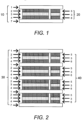
FIG. 1 is a diagram depicting a cross section of a nonlimiting embodiment of a super-capacitor of the present invention wherein a single super-capacitor is connected in parallel with an integrated electrochemical cell to provide voltage protection. -
FIG. 2 is a diagram depicting a cross section of an alternative nonlimiting embodiment of a super-capacitor of the present invention as a side-by-side configuration comprising multiple cells, each connected to the associated super-capacitor cell and forming two stacks, one of electrochemical cells and another of the associated super-capacitor cells that are connected in parallel. Parallel connected electrochemical battery stack and super-capacitor stack. (Cross-section view)-The numeric indicators have identical properties as the co-responding indicators inFIG. 1 . -
FIG. 3 is a diagram depicting a cross section of yet another embodiment of an integrated assembly of electrochemical fuel-cell and super-capacitor stack. -
FIG. 4 is a diagram depicting a cross section of three cells in a similar configuration toFIG. 3 as a combined and integrated super-capacitor stack of the three cells. The numeric indicators have identical properties as the co-responding indicators inFIG. 3 . -
FIG. 5 shows a configuration of the present invention wherein a super-capacitor is embedded within a single electrochemical cell, in particular a battery cell. - The invention relates devices and methods for production of devices which internally integrate a super-capacitor, also referred to as a double-capacitor or ultra-capacitor, or stack thereof, with an energy source.
- In simplest form, the device of the present invention comprises a super-capacitor cell comprising a top current collector, a top super-capacitor electrode, a super-capacitor electrolyte membrane, a bottom super-capacitor electrode and a bottom current collector or a stack of these super-capacitor cells.
- The device further comprises an energy source integrally connected to the super-capacitor cell or stack thereof.
- In one nonlimiting embodiment, the energy source is connected in parallel to the super-capacitor cell or stack thereof.
- According to the invention, components of the super-capacitor cell or stack thereof are embedded within the energy source between the top current collector and the bottom current collector of the super-capacitor cell or stack thereof.
- Any compatible renewable source of energy can be used as the energy source in the present invention. A nonlimiting example of an energy source useful in the present invention is a re-chargeable electrochemical cell which may be recharged from a primary energy conversion source such as a photovoltaic cell or a wide range of methods of supplying power. However, any cell type may be used if it meets the condition that the charged cell potential lies within the operational voltage limits of the super-capacitor it is connected to. Voltage regulation and cell balancing is obtained by integration of energy sources including, but in no way limited to, Zener diodes, batteries, solar cells, fuel cells, thermocouples, and mechanical to electrical power generators and any combinations thereof. Preferred is that the energy source used be compatible in the electric potential range and that it can be manufactured in accordance with established coating, printing or spraying technologies.
- In some nonlimiting embodiments, a higher potential cell, such as a rechargeable lithium cell having a potential exceeding the potential window of a super-capacitor having an aqueous electrolyte, may be used as the energy source and integrated with a super-capacitor. In this embodiment, the super-capacitor comprises a non-aqueous organic electrolyte and an asymmetric electrode material such as, but not limited to, a cobalt oxide based material thus raising the maximum potential of each super-capacitor cell in the stack to a maximum of approximately 4.1V.
- Various nonlimiting embodiments of devices of the present invention are depicted in
FIGS. 1 -6. -
FIG. 1 illustrates the basic integration of a single electrochemical cell as the energy source with the associated super-capacitor connected in parallel. As shown therein, the super-capacitor 10 comprises a topcurrent collector 1 adjacent to a topsuper-capacitor electrode 2, anelectrolyte membrane 3, a bottomsuper-capacitor electrode 4 and a bottomcurrent collector 7. Connected in parallel to the super-capacitor 10 is the singleelectrochemical cell 20, also referred to herein as a battery, comprising anegative battery electrode 5 and apositive battery electrode 6 separated by anelectrolyte membrane 3. -
FIG. 2 illustrates a nonlimiting embodiment comprising asuper-capacitor stack 30 in a side-by-side configuration with stacked electrochemical cells orbatteries 40, each connected to the associated super-capacitor cells in parallel. - In the nonlimiting embodiments depicted in
FIGs 1 and 2 , an air gap separates the super-capacitor cell or stack from the energy source. In an alternative embodiment, an electrical insulating material may be used. These materials are characterized as having a very low electrical conductivity. Examples of electrical insulating materials which can be used include, but are not limited to, rubberlike polymers and most plastics. Alternatively, materials having the property of semiconduction may be used as well as ionically conducting materials such as polymeric perfluoro-sulfonates (PFSA) materials. -
FIG. 3 shows another nonlimiting embodiment of the present invention with an integrated assembly of an energy source and a super-capacitor stack. In this nonlimiting embodiment, the energy source comprises a fuel cell.FIG. 3 shows that topcurrent collector 1, followed by a fuel cellgas diffusion layer 8, followed by a negativefuel cell electrode 9, followed by the topsuper-capacitor electrode 2, followed by theelectrolyte membrane 3, followed by the bottomsuper-capacitor electrode 4, followed by a positivefuel cell electrode 12, followed by a fuel cellgas diffusion layer 8 and a bottomcurrent collector 7. -
FIG. 4 illustrates a similar configuration toFIG. 3 with multiple super-capacitor cells and multiple fuel cells. The numeric indicators have identical properties as the co-responding indicators inFIG. 3 . -
FIG. 5 shows a configuration of the present invention wherein a super-capacitor is embedded within a single electrochemical cell, in particular a battery.FIG. 5 shows that topcurrent collector 1, followed by anegative battery electrode 5, followed by the topsuper-capacitor electrode 2, followed by theelectrolyte membrane 3, followed by the bottomsuper-capacitor electrode 4, followed by apositive battery electrode 6, and a bottomcurrent collector 7. - High discharge rates lead to rapid resistive heating of the device. Accordingly, the current collectors of the device have dual functions of conducting considerable current and diffusing heat resulting from resistive heating to the surroundings. It is desirable that current drain is controlled within acceptable limits by means of restraint circuitry and that an adequate dispersal of heat from the device to surroundings. In one nonlimiting embodiment, a thermal diffuser, such as treated aluminum is applied. Suitable materials are characterized by chemical stability and the ability to conduct electrons adequately without leading to thermal degradation due to resistive heating. Nonlimiting examples of materials which can be used in the top and bottom super-capacitor current collectors of the present invention include metals such as aluminum, copper or nickel foil, graphite foil as well as bipolar plates fabricated from carbon composites containing graphite, graphene or conducting carbon fiber.
- Nonlimiting examples of materials which can be used in the top and bottom super-capacitor electrodes include mixtures of activated high surface area carbon, binder and gelled or polymer electrolyte and activated high surface area carbon and a PFSA ionomer electrolyte.
- Nonlimiting examples of materials which can be used in the electrolyte membrane include, gelled electrolytes in a porous separator, polymer electrolytes and perfluorosulfonic acid (PFSA) ionomer membranes.
- In embodiments of the present invention wherein the energy source is a battery, nonlimiting examples of materials used in the negative battery electrode include mixtures of metal hydride powder, binder and gelled alkaline electrolyte as well as other appropriate electrode materials dependent upon the battery type selected. Nonlimiting examples of materials used in positive battery electrode include of e.g. nickel oxy-hydroxide powder, a binder and a gelled electrolyte. In this nonlimiting embodiment, a nickel-metal hydride (Ni-MH) cell or battery is used. However, as will be understood by the skilled artisan upon reading this disclosure, any type of rechargeable electrochemical cell that is compatible with the potential window of the integrated capacitor can be used as the energy source.
- In one nonlimiting embodiment, a lead acid type battery can be used as the energy source.
- In embodiments of the present invention wherein the energy source is a fuel cell, nonlimiting examples of materials which can be used in the negative fuel cell electrode include platinum/ruthenium catalyst and PFSA ionomer membranes electrolyte. Nonlimiting examples of materials used in the positive fuel cell electrode include platinum catalyst and PFSA ionomer electrolyte.
- As will be understood by the skilled artisan upon reading this disclosure, alternative materials for components of the super-capacitors than those specifically disclosed herein as well as alternative materials for the components of the energy sources than those specifically disclosed herein and known to those skilled in the art can be used.
- The invention also relates to methods of producing super-capacitor cells or stacks thereof serially connected and/or integrated with an energy source which are maintained in balanced coordination and protected during charge and discharge thereby preventing cell over-voltage and cell imbalance which reduce the performance reliability and lifetime of such super-capacitor stacks. In this respect the use of established coating methods to fabricate thin and flexible layered composite devices is optimal. The manufacturing processes involved have become well established and those who are versed in the art of fabricating electrochemical cells such as lithium cells and are revealed in the prior art citations herein. The coating processes required to fulfill complex requirements of porosity, electronic and ionic conductivity for combined electrochemical devices and super-capacitors have become an established means of manufacture of the devices disclosed. The different layers in the super-capacitor laminate are made by successively applying the various superimposed layers. The method involves primarily coating an electrode onto a current collector followed by successive superimposition by coating the other functional layers.
- The coating technique obviates the establishment of traditional and cumbersome means of connection in parallel of the electrochemical cell to the capacitor, thereby avoiding costly external circuits. The high energy density and low power density of the electrochemical cell is supplemented by the high intrinsic power density of the super-capacitor which has in general a limited energy density. This enables rapid and copious recharge cycles of the super-capacitor stack and voltage regulation and control of each super-capacitor in the stack.
- The invention utilizes coating materials specifically adapted to integration of electrochemical cells and super-capacitors devices. Various coating materials known to those skilled in the art can be adapted for use in accordance with the present invention and applied in manufacture of the devices of the present invention via conventional coating processes such as described in published
U.S. Patent Application Nos. 20080206616 and20080075842 , - For example,
U.S. Published Patent Application 20080206616 discloses the formulation and processing of highly porous catalyst coated membranes, sprayable inks and processes for forming catalyst coated membranes all of which can be adapted for use in the present invention. The disclosed sprayable ink comprising catalyst particles, polymer electrolyte ionomer, and a vehicle for dispersing the catalyst particles and the polymer electrolyte ionomer as well as the disclosed process comprising the steps of depositing an ink comprising catalyst particles and a vehicle onto a membrane and vaporizing from 40 to 95 weight percent of the vehicle from the sprayed ink under conditions effective to form a catalyst layer on the membrane can be used in coating processes to produce the devices of the present invention. - In particular, the coating technique can be applied to the cathodic and anodic electrode materials as well as to the electrode materials of the super-capacitor. The same process equipment is also suitable for applying the electrolyte or semiconduction membrane materials. Those versed in the art of coating are aware of established techniques for satisfying the rheological demands of the process.
- Another nonlimiting example of coatings and coating processes which can be adapted for use in the manufacture of the devices of the present invention includes the coatings and processes used for preparing catalyst coated membranes and membrane electrode assemblies for use in direct methanol fuel cells. In these processes, cathode and anode layers are formed by spraying catalyst-containing inks onto a novel framed electrolytic membrane to form a catalyst coated membrane. The spraying process optionally employs one or more masks, which carefully control where the catalyst-containing ink is deposited. Following application of the cathode and anode layers, diffusion layers are prepared and inserted onto the catalyst coated membranes, and pressed to form membrane electrode assemblies.
- Methods of fabricating electrodes for super-capacitors such as disclosed in published
U.S. Patent Application 20150318121A1 , wherein the activated carbon is mixed with a binding material within a time period long enough for completion of the coagulation process, following which the mass thus obtained is packed to remove the dispersed medium and is used for formation (molding) of the electrodes, can be used in production of the super-capacitors of the devices of the present invention. - Another method for production of a super-capacitor which can be adapted for use in the device of the present invention is described by Wang et al. (Sci. China Technol. Sci. 2015 58: 1779. In this super-capacitor, pseudo-capacitance is produced from the electrode and the electrolyte of super-capacitors to simultaneously achieve high energy density and power density. Layered transition metal hydroxides (Ni(OH)2 and Co(OH)2) are introduced as electrodes, followed by exploration of the effect of the active materials and the substrate on the electrochemical behavior. Various redox electrolytes are utilized to improve the specific capacitance of an electrolyte. Using these disclosed methodologies, an appropriate electrode and a dedicated electrolyte can be selected in order to achieve high electrochemical performance of super-capacitors used in the devices of the present invention.
- Additional methods and components which can be used for production of super-capacitors used in the devices of present invention are disclosed in Frontiers of Energy (A Review for Aqueous Electrochemical Supercapacitors, Article Date 08/05/15 18:33), the thesis of Steffen Thrane Vindt (Development of a Sustainable, Cost-Effective Supercapacitor for Energy Storage (SuperCap), PhD Thesis, University of Southern Denmark (2016)), Vindt et al. (Appl. Phys. A (2016) 122: 64) and
- In addition, published
U.S. Patent Application 20030064265A1 , discloses electro-catalyst powders and methods for producing electro-catalyst powders, such as carbon composite electro-catalyst powders, useful in production of the devices of the present invention. The powders have a well-controlled microstructure and morphology. The method includes forming the particles from an aerosol of precursors by heating the aerosol to a relatively low temperature, such as not greater than about 400°C. This coating technique is particularly useful in applying the cathodic and anodic electrode materials as well as the electrode materials of the super-capacitor. - Nonlimiting methodologies for production and the fuel cell components disclosed in Published
U.S. Patent Application 20080286632A1 , can also be used in the manufacture of devices of the present invention with this type of energy source. - Nonlimiting methods and components for fabricating solar cells such as described in published
U.S. Patent Application 20080289683A1 as well as by Green, M. A. (Solar Energy 2003 74 (3): 181-192) can be used in the manufacture of devices of the present invention with this type of energy source. - Electrolytes that can remain stable up to 2.5V are useful in various batteries of high capacity and power density useful in the devices of the present invention. In one nonlimiting embodiment, wherein the energy source is a battery, a composition of an aqueous electrolyte comprising one or more non-aqueous solvents and a salt, which has a larger electrochemical stability window than a pure aqueous electrolyte is used. Example of other materials expected to be useful as 2.5 V aqueous hybrid electrolytes include, but are not limited to, activated carbon derived from pistachio nutshells (>2.400 m2, > 200 F/g) prepared by pyrolysis at 300oC followed by treatment with CaCl2 followed by KOH treatment and pyrolysis at 900°C, pyrolized sugar with graphene oxide, and high specific area graphite flakes prepared by treating graphitized bituminous coal with KOH.
- Additional examples of electrolyte materials useful in energy sources of the present invention are disclosed by Zhong et al. (Chem. Soc. Rev. 2015 44: 7484).
- Considerable advantages can be gained by producing a combined stack of high power density capacitors and selected energy source in accordance with the present invention to increase energy storage capacity and performance, reduce the mass of the device and utilize the space available for energy storage and transfer optimally. The integrated voltage balancing and protection circuit removes any need for an external circuit since the individual super-capacitor cell voltages and thereby also the individual super-capacitor charges and discharges are controlled by the integrated energy source leaving each cell at the same voltage after any charge or discharge period.
- The following nonlimiting example is provided to further illustrate the present invention.
- An aqueous capacitor having a potential window exceeding the conventional established maximum potential of 1.2V has been developed with a view of expanding the potential window to accommodate integration of alkaline batteries and rechargeable lead-acid type cells at 2.1V in a configuration of the type disclosed in
FIG. 1 . In this embodiment, the two types of cell are isolated from each other, each having its own separate electrolyte.
Claims (6)
- A device which internally controls and regulates voltage of a super-capacitor cell during charge-discharge cycles, said device comprising:a super-capacitor cell comprising a top current collector (1), a top super-capacitor electrode (2), a super-capacitor electrolyte membrane (3), a bottom super-capacitor electrode (4) and a bottom current collector (7); andan energy source internally connected to the super-capacitor cell, characterized in that:
the top super-capacitor electrode (2), the super-capacitor electrolyte membrane (3), and the bottom super-capacitor electrode (4) of the super-capacitor cell are embedded within the energy source between the top current collector (1) and the bottom current collector (7) of said super-capacitor cell. - A device comprising a stack of devices according to claim 1.
- The device of any previous claim wherein the charged cell potential of the energy source (20) lies within the operational voltage limits of the super-capacitor cell (10) .
- The device of any preceding claim wherein the energy source is a Zener diode, battery, solar cell, fuel cell, thermocouple, or mechanical to electrical power generator or any combination thereof.
- The device of any previous claims, wherein the energy source comprises the top current collection (1) followed by a fuel cell gas diffusion layer (8), followed by a negative fuel cell electrode (9); and a positive fuel cell electrode (12), followed by a fuel cell gas diffusion layer (8), followed by the bottom current collector (7), wherein the top super-capacitor electrode (2), the super-capacitor electrolyte membrane (3), and the bottom super-capacitor electrode (4) of the super-capacitor cell are embedded within the energy source between the negative fuel cell electrode (9) and the positive fuel cell electrode (12).
- The device of any of the preceding claims which is manufactured by a coating method.
Applications Claiming Priority (2)
| Application Number | Priority Date | Filing Date | Title |
|---|---|---|---|
| US201662433354P | 2016-12-13 | 2016-12-13 | |
| PCT/EP2017/082595 WO2018108994A1 (en) | 2016-12-13 | 2017-12-13 | Electrochemical and capacitative energy storage device and method of manufacture |
Publications (2)
| Publication Number | Publication Date |
|---|---|
| EP3555897A1 EP3555897A1 (en) | 2019-10-23 |
| EP3555897B1 true EP3555897B1 (en) | 2024-09-25 |
Family
ID=61017885
Family Applications (1)
| Application Number | Title | Priority Date | Filing Date |
|---|---|---|---|
| EP17832755.7A Active EP3555897B1 (en) | 2016-12-13 | 2017-12-13 | Electrochemical and capacitative energy storage device and method of manufacture |
Country Status (3)
| Country | Link |
|---|---|
| US (1) | US10964488B2 (en) |
| EP (1) | EP3555897B1 (en) |
| WO (1) | WO2018108994A1 (en) |
Families Citing this family (7)
| Publication number | Priority date | Publication date | Assignee | Title |
|---|---|---|---|---|
| CA3053788A1 (en) | 2017-02-20 | 2018-08-23 | The Research Foundation For The State University Of New York | Multi-cell multi-layer high voltage supercapacitor |
| CN111477466B (en) * | 2019-01-23 | 2021-04-02 | 清华大学 | Charging method of self-charging super capacitor |
| CN111477459B (en) * | 2019-01-23 | 2021-04-02 | 清华大学 | Self-charging supercapacitors |
| CN111477472B (en) * | 2019-01-23 | 2021-04-02 | 清华大学 | Self-charging supercapacitors |
| CN111952080B (en) * | 2019-05-17 | 2022-08-16 | 清华大学 | Energy storage device capable of being charged in situ |
| JP7600263B2 (en) * | 2020-04-24 | 2024-12-16 | オカド・イノベーション・リミテッド | Energy storage systems for load handling equipment. |
| WO2024088780A1 (en) | 2022-10-25 | 2024-05-02 | Innocell Aps | Assembly of aluminium electrodes and barrier layers for super capacitor embedding a standard capacitor and having improved resistance to corrosion |
Citations (2)
| Publication number | Priority date | Publication date | Assignee | Title |
|---|---|---|---|---|
| US20120114982A1 (en) * | 2010-11-04 | 2012-05-10 | Mitsubishi Electric Corporation | Energy storage device cell |
| US20160042877A1 (en) * | 2012-03-18 | 2016-02-11 | Elbit Systems Land And C4I Ltd | Aqueous-based electric double-layer capacitor |
Family Cites Families (10)
| Publication number | Priority date | Publication date | Assignee | Title |
|---|---|---|---|---|
| US6967183B2 (en) | 1998-08-27 | 2005-11-22 | Cabot Corporation | Electrocatalyst powders, methods for producing powders and devices fabricated from same |
| US20080289683A1 (en) | 2004-06-04 | 2008-11-27 | Timothy Michael Walsh | Thin-Film Solar Cell Interconnection |
| WO2007048612A2 (en) | 2005-10-27 | 2007-05-03 | Ird Fuel Cells A/S | Membrane electrode assemblies for dmfc having catalyst concentration gradient |
| US20080075842A1 (en) | 2006-09-22 | 2008-03-27 | Cabot Corporation | Processes, Framed Membranes and Masks for Forming Catalyst Coated Membranes and Membrane Electrode Assemblies |
| US20080206616A1 (en) | 2007-02-27 | 2008-08-28 | Cabot Corporation | Catalyst coated membranes and sprayable inks and processes for forming same |
| US8968296B2 (en) * | 2012-06-26 | 2015-03-03 | Covidien Lp | Energy-harvesting system, apparatus and methods |
| US20150318121A1 (en) | 2012-12-03 | 2015-11-05 | Obschestvo S Organichennoy Otvetstvennostyu "Tovarischestvo Energeticheskikh 1 Electromobilnyk | Method for manufacturing electrical double layer capacitor electrodes |
| US10608284B2 (en) * | 2013-11-15 | 2020-03-31 | The Regents Of The University Of California | Electrochemical devices comprising compressed gas solvent electrolytes |
| WO2016149919A1 (en) * | 2015-03-25 | 2016-09-29 | GM Global Technology Operations LLC | Capacitor-battery hybrid formed by plasma powder electrode coating |
| EP3479389B1 (en) | 2016-06-29 | 2020-08-05 | Innocell Aps | A supercapacitor and a method for expanding the voltage range of an aqueous electrolyte supercapacitor |
-
2017
- 2017-12-13 US US16/466,671 patent/US10964488B2/en active Active
- 2017-12-13 EP EP17832755.7A patent/EP3555897B1/en active Active
- 2017-12-13 WO PCT/EP2017/082595 patent/WO2018108994A1/en not_active Ceased
Patent Citations (2)
| Publication number | Priority date | Publication date | Assignee | Title |
|---|---|---|---|---|
| US20120114982A1 (en) * | 2010-11-04 | 2012-05-10 | Mitsubishi Electric Corporation | Energy storage device cell |
| US20160042877A1 (en) * | 2012-03-18 | 2016-02-11 | Elbit Systems Land And C4I Ltd | Aqueous-based electric double-layer capacitor |
Also Published As
| Publication number | Publication date |
|---|---|
| US10964488B2 (en) | 2021-03-30 |
| US20190295781A1 (en) | 2019-09-26 |
| EP3555897A1 (en) | 2019-10-23 |
| WO2018108994A1 (en) | 2018-06-21 |
Similar Documents
| Publication | Publication Date | Title |
|---|---|---|
| EP3555897B1 (en) | Electrochemical and capacitative energy storage device and method of manufacture | |
| CN100578700C (en) | Lithium ion capacitor | |
| CN104078701B (en) | Charge storage element | |
| CN102576613B (en) | Fuel Cell/Supercapacitor/Battery Power Systems for Vehicle Propulsion | |
| CN1735949B (en) | Electrical storage device and method for manufacturing electrical storage device | |
| CN101138058B (en) | Lithium ion capacitor | |
| CN103380469B (en) | Electrode foils, current collectors, electrodes, and power storage components using them | |
| JP4633960B2 (en) | Power storage system for automobiles | |
| CN102301439B (en) | Wound-type accumulator | |
| JP7042589B2 (en) | Negative electrode | |
| EP3379599B1 (en) | Composite electrolyte, secondary battery, battery pack, and vehicle | |
| EP2930728A1 (en) | Nonaqueous lithium storage element | |
| CN103715383B (en) | Charge storage element | |
| KR20080000614A (en) | Anode Active Material for Power Storage Devices | |
| JP7395213B2 (en) | Separation membrane for electrochemical devices and electrochemical devices including the same | |
| CN106507692A (en) | lithium secondary battery | |
| EP3005466A1 (en) | A segmented fuel cell-battery passive hybrid system | |
| US10319536B1 (en) | High-capacity electrical energy storage device | |
| KR20220100537A (en) | Cathode, and Lithium Secondary Battery Comprising the same | |
| CN101326601B (en) | Lithium ion capacitor | |
| JP7027190B2 (en) | State estimation method, estimation device, system for non-aqueous lithium-type power storage element | |
| WO2022175043A1 (en) | Hybrid electrode | |
| KR101269300B1 (en) | Lithium ion rechargeable battery and process for producing the lithium ion rechargeable battery | |
| US20200067142A1 (en) | Lithium Ion Accumulator In Sandwich Design And Method For The Production Thereof | |
| JP2018014398A (en) | Nonaqueous lithium power storage element |
Legal Events
| Date | Code | Title | Description |
|---|---|---|---|
| STAA | Information on the status of an ep patent application or granted ep patent |
Free format text: STATUS: UNKNOWN |
|
| STAA | Information on the status of an ep patent application or granted ep patent |
Free format text: STATUS: THE INTERNATIONAL PUBLICATION HAS BEEN MADE |
|
| PUAI | Public reference made under article 153(3) epc to a published international application that has entered the european phase |
Free format text: ORIGINAL CODE: 0009012 |
|
| STAA | Information on the status of an ep patent application or granted ep patent |
Free format text: STATUS: REQUEST FOR EXAMINATION WAS MADE |
|
| 17P | Request for examination filed |
Effective date: 20190701 |
|
| AK | Designated contracting states |
Kind code of ref document: A1 Designated state(s): AL AT BE BG CH CY CZ DE DK EE ES FI FR GB GR HR HU IE IS IT LI LT LU LV MC MK MT NL NO PL PT RO RS SE SI SK SM TR |
|
| AX | Request for extension of the european patent |
Extension state: BA ME |
|
| DAV | Request for validation of the european patent (deleted) | ||
| DAX | Request for extension of the european patent (deleted) | ||
| STAA | Information on the status of an ep patent application or granted ep patent |
Free format text: STATUS: EXAMINATION IS IN PROGRESS |
|
| 17Q | First examination report despatched |
Effective date: 20220218 |
|
| GRAP | Despatch of communication of intention to grant a patent |
Free format text: ORIGINAL CODE: EPIDOSNIGR1 |
|
| STAA | Information on the status of an ep patent application or granted ep patent |
Free format text: STATUS: GRANT OF PATENT IS INTENDED |
|
| INTG | Intention to grant announced |
Effective date: 20240423 |
|
| GRAS | Grant fee paid |
Free format text: ORIGINAL CODE: EPIDOSNIGR3 |
|
| GRAA | (expected) grant |
Free format text: ORIGINAL CODE: 0009210 |
|
| STAA | Information on the status of an ep patent application or granted ep patent |
Free format text: STATUS: THE PATENT HAS BEEN GRANTED |
|
| AK | Designated contracting states |
Kind code of ref document: B1 Designated state(s): AL AT BE BG CH CY CZ DE DK EE ES FI FR GB GR HR HU IE IS IT LI LT LU LV MC MK MT NL NO PL PT RO RS SE SI SK SM TR |
|
| REG | Reference to a national code |
Ref country code: GB Ref legal event code: FG4D |
|
| REG | Reference to a national code |
Ref country code: CH Ref legal event code: EP |
|
| REG | Reference to a national code |
Ref country code: DE Ref legal event code: R096 Ref document number: 602017085108 Country of ref document: DE |
|
| REG | Reference to a national code |
Ref country code: IE Ref legal event code: FG4D |
|
| REG | Reference to a national code |
Ref country code: LT Ref legal event code: MG9D |
|
| PG25 | Lapsed in a contracting state [announced via postgrant information from national office to epo] |
Ref country code: NO Free format text: LAPSE BECAUSE OF FAILURE TO SUBMIT A TRANSLATION OF THE DESCRIPTION OR TO PAY THE FEE WITHIN THE PRESCRIBED TIME-LIMIT Effective date: 20241225 |
|
| PG25 | Lapsed in a contracting state [announced via postgrant information from national office to epo] |
Ref country code: GR Free format text: LAPSE BECAUSE OF FAILURE TO SUBMIT A TRANSLATION OF THE DESCRIPTION OR TO PAY THE FEE WITHIN THE PRESCRIBED TIME-LIMIT Effective date: 20241226 Ref country code: FI Free format text: LAPSE BECAUSE OF FAILURE TO SUBMIT A TRANSLATION OF THE DESCRIPTION OR TO PAY THE FEE WITHIN THE PRESCRIBED TIME-LIMIT Effective date: 20240925 |
|
| PG25 | Lapsed in a contracting state [announced via postgrant information from national office to epo] |
Ref country code: BG Free format text: LAPSE BECAUSE OF FAILURE TO SUBMIT A TRANSLATION OF THE DESCRIPTION OR TO PAY THE FEE WITHIN THE PRESCRIBED TIME-LIMIT Effective date: 20240925 |
|
| PG25 | Lapsed in a contracting state [announced via postgrant information from national office to epo] |
Ref country code: LV Free format text: LAPSE BECAUSE OF FAILURE TO SUBMIT A TRANSLATION OF THE DESCRIPTION OR TO PAY THE FEE WITHIN THE PRESCRIBED TIME-LIMIT Effective date: 20240925 |
|
| PG25 | Lapsed in a contracting state [announced via postgrant information from national office to epo] |
Ref country code: RS Free format text: LAPSE BECAUSE OF FAILURE TO SUBMIT A TRANSLATION OF THE DESCRIPTION OR TO PAY THE FEE WITHIN THE PRESCRIBED TIME-LIMIT Effective date: 20241225 |
|
| REG | Reference to a national code |
Ref country code: NL Ref legal event code: MP Effective date: 20240925 |
|
| PG25 | Lapsed in a contracting state [announced via postgrant information from national office to epo] |
Ref country code: RS Free format text: LAPSE BECAUSE OF FAILURE TO SUBMIT A TRANSLATION OF THE DESCRIPTION OR TO PAY THE FEE WITHIN THE PRESCRIBED TIME-LIMIT Effective date: 20241225 Ref country code: NO Free format text: LAPSE BECAUSE OF FAILURE TO SUBMIT A TRANSLATION OF THE DESCRIPTION OR TO PAY THE FEE WITHIN THE PRESCRIBED TIME-LIMIT Effective date: 20241225 Ref country code: LV Free format text: LAPSE BECAUSE OF FAILURE TO SUBMIT A TRANSLATION OF THE DESCRIPTION OR TO PAY THE FEE WITHIN THE PRESCRIBED TIME-LIMIT Effective date: 20240925 Ref country code: GR Free format text: LAPSE BECAUSE OF FAILURE TO SUBMIT A TRANSLATION OF THE DESCRIPTION OR TO PAY THE FEE WITHIN THE PRESCRIBED TIME-LIMIT Effective date: 20241226 Ref country code: FI Free format text: LAPSE BECAUSE OF FAILURE TO SUBMIT A TRANSLATION OF THE DESCRIPTION OR TO PAY THE FEE WITHIN THE PRESCRIBED TIME-LIMIT Effective date: 20240925 Ref country code: BG Free format text: LAPSE BECAUSE OF FAILURE TO SUBMIT A TRANSLATION OF THE DESCRIPTION OR TO PAY THE FEE WITHIN THE PRESCRIBED TIME-LIMIT Effective date: 20240925 |
|
| REG | Reference to a national code |
Ref country code: AT Ref legal event code: MK05 Ref document number: 1727388 Country of ref document: AT Kind code of ref document: T Effective date: 20240925 |
|
| PG25 | Lapsed in a contracting state [announced via postgrant information from national office to epo] |
Ref country code: NL Free format text: LAPSE BECAUSE OF FAILURE TO SUBMIT A TRANSLATION OF THE DESCRIPTION OR TO PAY THE FEE WITHIN THE PRESCRIBED TIME-LIMIT Effective date: 20240925 |
|
| PG25 | Lapsed in a contracting state [announced via postgrant information from national office to epo] |
Ref country code: IS Free format text: LAPSE BECAUSE OF FAILURE TO SUBMIT A TRANSLATION OF THE DESCRIPTION OR TO PAY THE FEE WITHIN THE PRESCRIBED TIME-LIMIT Effective date: 20250125 Ref country code: PT Free format text: LAPSE BECAUSE OF FAILURE TO SUBMIT A TRANSLATION OF THE DESCRIPTION OR TO PAY THE FEE WITHIN THE PRESCRIBED TIME-LIMIT Effective date: 20250127 |
|
| PG25 | Lapsed in a contracting state [announced via postgrant information from national office to epo] |
Ref country code: SM Free format text: LAPSE BECAUSE OF FAILURE TO SUBMIT A TRANSLATION OF THE DESCRIPTION OR TO PAY THE FEE WITHIN THE PRESCRIBED TIME-LIMIT Effective date: 20240925 Ref country code: RO Free format text: LAPSE BECAUSE OF FAILURE TO SUBMIT A TRANSLATION OF THE DESCRIPTION OR TO PAY THE FEE WITHIN THE PRESCRIBED TIME-LIMIT Effective date: 20240925 |
|
| PG25 | Lapsed in a contracting state [announced via postgrant information from national office to epo] |
Ref country code: ES Free format text: LAPSE BECAUSE OF FAILURE TO SUBMIT A TRANSLATION OF THE DESCRIPTION OR TO PAY THE FEE WITHIN THE PRESCRIBED TIME-LIMIT Effective date: 20240925 |
|
| PG25 | Lapsed in a contracting state [announced via postgrant information from national office to epo] |
Ref country code: AT Free format text: LAPSE BECAUSE OF FAILURE TO SUBMIT A TRANSLATION OF THE DESCRIPTION OR TO PAY THE FEE WITHIN THE PRESCRIBED TIME-LIMIT Effective date: 20240925 Ref country code: EE Free format text: LAPSE BECAUSE OF FAILURE TO SUBMIT A TRANSLATION OF THE DESCRIPTION OR TO PAY THE FEE WITHIN THE PRESCRIBED TIME-LIMIT Effective date: 20240925 |
|
| PG25 | Lapsed in a contracting state [announced via postgrant information from national office to epo] |
Ref country code: CZ Free format text: LAPSE BECAUSE OF FAILURE TO SUBMIT A TRANSLATION OF THE DESCRIPTION OR TO PAY THE FEE WITHIN THE PRESCRIBED TIME-LIMIT Effective date: 20240925 Ref country code: PL Free format text: LAPSE BECAUSE OF FAILURE TO SUBMIT A TRANSLATION OF THE DESCRIPTION OR TO PAY THE FEE WITHIN THE PRESCRIBED TIME-LIMIT Effective date: 20240925 |
|
| PG25 | Lapsed in a contracting state [announced via postgrant information from national office to epo] |
Ref country code: SK Free format text: LAPSE BECAUSE OF FAILURE TO SUBMIT A TRANSLATION OF THE DESCRIPTION OR TO PAY THE FEE WITHIN THE PRESCRIBED TIME-LIMIT Effective date: 20240925 Ref country code: IT Free format text: LAPSE BECAUSE OF FAILURE TO SUBMIT A TRANSLATION OF THE DESCRIPTION OR TO PAY THE FEE WITHIN THE PRESCRIBED TIME-LIMIT Effective date: 20240925 |
|
| REG | Reference to a national code |
Ref country code: DE Ref legal event code: R097 Ref document number: 602017085108 Country of ref document: DE |
|
| PG25 | Lapsed in a contracting state [announced via postgrant information from national office to epo] |
Ref country code: MC Free format text: LAPSE BECAUSE OF FAILURE TO SUBMIT A TRANSLATION OF THE DESCRIPTION OR TO PAY THE FEE WITHIN THE PRESCRIBED TIME-LIMIT Effective date: 20240925 |
|
| PG25 | Lapsed in a contracting state [announced via postgrant information from national office to epo] |
Ref country code: DK Free format text: LAPSE BECAUSE OF FAILURE TO SUBMIT A TRANSLATION OF THE DESCRIPTION OR TO PAY THE FEE WITHIN THE PRESCRIBED TIME-LIMIT Effective date: 20240925 |
|
| REG | Reference to a national code |
Ref country code: CH Ref legal event code: PL |
|
| PLBE | No opposition filed within time limit |
Free format text: ORIGINAL CODE: 0009261 |
|
| STAA | Information on the status of an ep patent application or granted ep patent |
Free format text: STATUS: NO OPPOSITION FILED WITHIN TIME LIMIT |
|
| PG25 | Lapsed in a contracting state [announced via postgrant information from national office to epo] |
Ref country code: LU Free format text: LAPSE BECAUSE OF NON-PAYMENT OF DUE FEES Effective date: 20241213 |
|
| 26N | No opposition filed |
Effective date: 20250626 |
|
| PG25 | Lapsed in a contracting state [announced via postgrant information from national office to epo] |
Ref country code: SE Free format text: LAPSE BECAUSE OF FAILURE TO SUBMIT A TRANSLATION OF THE DESCRIPTION OR TO PAY THE FEE WITHIN THE PRESCRIBED TIME-LIMIT Effective date: 20240925 |
|
| REG | Reference to a national code |
Ref country code: BE Ref legal event code: MM Effective date: 20241231 |
|
| PG25 | Lapsed in a contracting state [announced via postgrant information from national office to epo] |
Ref country code: BE Free format text: LAPSE BECAUSE OF NON-PAYMENT OF DUE FEES Effective date: 20241231 |
|
| PG25 | Lapsed in a contracting state [announced via postgrant information from national office to epo] |
Ref country code: CH Free format text: LAPSE BECAUSE OF NON-PAYMENT OF DUE FEES Effective date: 20241231 |
|
| PG25 | Lapsed in a contracting state [announced via postgrant information from national office to epo] |
Ref country code: IE Free format text: LAPSE BECAUSE OF NON-PAYMENT OF DUE FEES Effective date: 20241213 |
|
| PGFP | Annual fee paid to national office [announced via postgrant information from national office to epo] |
Ref country code: DE Payment date: 20251211 Year of fee payment: 9 |
|
| PGFP | Annual fee paid to national office [announced via postgrant information from national office to epo] |
Ref country code: GB Payment date: 20251219 Year of fee payment: 9 |
|
| PG25 | Lapsed in a contracting state [announced via postgrant information from national office to epo] |
Ref country code: HR Free format text: LAPSE BECAUSE OF FAILURE TO SUBMIT A TRANSLATION OF THE DESCRIPTION OR TO PAY THE FEE WITHIN THE PRESCRIBED TIME-LIMIT Effective date: 20240925 |
|
| PGFP | Annual fee paid to national office [announced via postgrant information from national office to epo] |
Ref country code: FR Payment date: 20251229 Year of fee payment: 9 |