EP3555488B1 - Reduced electromagnetic signature of conforming conical seal fastener systems - Google Patents
Reduced electromagnetic signature of conforming conical seal fastener systems Download PDFInfo
- Publication number
- EP3555488B1 EP3555488B1 EP17880503.2A EP17880503A EP3555488B1 EP 3555488 B1 EP3555488 B1 EP 3555488B1 EP 17880503 A EP17880503 A EP 17880503A EP 3555488 B1 EP3555488 B1 EP 3555488B1
- Authority
- EP
- European Patent Office
- Prior art keywords
- fastener
- head
- sleeve
- core bolt
- seal element
- Prior art date
- Legal status (The legal status is an assumption and is not a legal conclusion. Google has not performed a legal analysis and makes no representation as to the accuracy of the status listed.)
- Active
Links
Images




Classifications
-
- B—PERFORMING OPERATIONS; TRANSPORTING
- B64—AIRCRAFT; AVIATION; COSMONAUTICS
- B64D—EQUIPMENT FOR FITTING IN OR TO AIRCRAFT; FLIGHT SUITS; PARACHUTES; ARRANGEMENT OR MOUNTING OF POWER PLANTS OR PROPULSION TRANSMISSIONS IN AIRCRAFT
- B64D45/00—Aircraft indicators or protectors not otherwise provided for
- B64D45/02—Lightning protectors; Static dischargers
-
- F—MECHANICAL ENGINEERING; LIGHTING; HEATING; WEAPONS; BLASTING
- F16—ENGINEERING ELEMENTS AND UNITS; GENERAL MEASURES FOR PRODUCING AND MAINTAINING EFFECTIVE FUNCTIONING OF MACHINES OR INSTALLATIONS; THERMAL INSULATION IN GENERAL
- F16B—DEVICES FOR FASTENING OR SECURING CONSTRUCTIONAL ELEMENTS OR MACHINE PARTS TOGETHER, e.g. NAILS, BOLTS, CIRCLIPS, CLAMPS, CLIPS OR WEDGES; JOINTS OR JOINTING
- F16B13/00—Dowels or other devices fastened in walls or the like by inserting them in holes made therein for that purpose
-
- F—MECHANICAL ENGINEERING; LIGHTING; HEATING; WEAPONS; BLASTING
- F16—ENGINEERING ELEMENTS AND UNITS; GENERAL MEASURES FOR PRODUCING AND MAINTAINING EFFECTIVE FUNCTIONING OF MACHINES OR INSTALLATIONS; THERMAL INSULATION IN GENERAL
- F16B—DEVICES FOR FASTENING OR SECURING CONSTRUCTIONAL ELEMENTS OR MACHINE PARTS TOGETHER, e.g. NAILS, BOLTS, CIRCLIPS, CLAMPS, CLIPS OR WEDGES; JOINTS OR JOINTING
- F16B13/00—Dowels or other devices fastened in walls or the like by inserting them in holes made therein for that purpose
- F16B13/12—Separate metal or non-separate or non-metal dowel sleeves fastened by inserting the screw, nail or the like
- F16B13/124—Separate metal or non-separate or non-metal dowel sleeves fastened by inserting the screw, nail or the like fastened by inserting a threaded element, e.g. screw or bolt
-
- F—MECHANICAL ENGINEERING; LIGHTING; HEATING; WEAPONS; BLASTING
- F16—ENGINEERING ELEMENTS AND UNITS; GENERAL MEASURES FOR PRODUCING AND MAINTAINING EFFECTIVE FUNCTIONING OF MACHINES OR INSTALLATIONS; THERMAL INSULATION IN GENERAL
- F16B—DEVICES FOR FASTENING OR SECURING CONSTRUCTIONAL ELEMENTS OR MACHINE PARTS TOGETHER, e.g. NAILS, BOLTS, CIRCLIPS, CLAMPS, CLIPS OR WEDGES; JOINTS OR JOINTING
- F16B19/00—Bolts without screw-thread; Pins, including deformable elements; Rivets
- F16B19/04—Rivets; Spigots or the like fastened by riveting
- F16B19/08—Hollow rivets; Multi-part rivets
- F16B19/10—Hollow rivets; Multi-part rivets fastened by expanding mechanically
- F16B19/1027—Multi-part rivets
- F16B19/1036—Blind rivets
- F16B19/1045—Blind rivets fastened by a pull - mandrel or the like
- F16B19/1072—Blind rivets fastened by a pull - mandrel or the like the pull-mandrel or the like comprising a thread and being rotated with respect to the rivet, thereby mechanically expanding and fastening the rivet
-
- F—MECHANICAL ENGINEERING; LIGHTING; HEATING; WEAPONS; BLASTING
- F16—ENGINEERING ELEMENTS AND UNITS; GENERAL MEASURES FOR PRODUCING AND MAINTAINING EFFECTIVE FUNCTIONING OF MACHINES OR INSTALLATIONS; THERMAL INSULATION IN GENERAL
- F16B—DEVICES FOR FASTENING OR SECURING CONSTRUCTIONAL ELEMENTS OR MACHINE PARTS TOGETHER, e.g. NAILS, BOLTS, CIRCLIPS, CLAMPS, CLIPS OR WEDGES; JOINTS OR JOINTING
- F16B23/00—Specially shaped nuts or heads of bolts or screws for rotations by a tool
-
- F—MECHANICAL ENGINEERING; LIGHTING; HEATING; WEAPONS; BLASTING
- F16—ENGINEERING ELEMENTS AND UNITS; GENERAL MEASURES FOR PRODUCING AND MAINTAINING EFFECTIVE FUNCTIONING OF MACHINES OR INSTALLATIONS; THERMAL INSULATION IN GENERAL
- F16B—DEVICES FOR FASTENING OR SECURING CONSTRUCTIONAL ELEMENTS OR MACHINE PARTS TOGETHER, e.g. NAILS, BOLTS, CIRCLIPS, CLAMPS, CLIPS OR WEDGES; JOINTS OR JOINTING
- F16B31/00—Screwed connections specially modified in view of tensile load; Break-bolts
- F16B31/06—Screwed connections specially modified in view of tensile load; Break-bolts having regard to possibility of fatigue rupture
-
- F—MECHANICAL ENGINEERING; LIGHTING; HEATING; WEAPONS; BLASTING
- F16—ENGINEERING ELEMENTS AND UNITS; GENERAL MEASURES FOR PRODUCING AND MAINTAINING EFFECTIVE FUNCTIONING OF MACHINES OR INSTALLATIONS; THERMAL INSULATION IN GENERAL
- F16B—DEVICES FOR FASTENING OR SECURING CONSTRUCTIONAL ELEMENTS OR MACHINE PARTS TOGETHER, e.g. NAILS, BOLTS, CIRCLIPS, CLAMPS, CLIPS OR WEDGES; JOINTS OR JOINTING
- F16B35/00—Screw-bolts; Stay-bolts; Screw-threaded studs; Screws; Set screws
- F16B35/04—Screw-bolts; Stay-bolts; Screw-threaded studs; Screws; Set screws with specially-shaped head or shaft in order to fix the bolt on or in an object
- F16B35/06—Specially-shaped heads
-
- F—MECHANICAL ENGINEERING; LIGHTING; HEATING; WEAPONS; BLASTING
- F16—ENGINEERING ELEMENTS AND UNITS; GENERAL MEASURES FOR PRODUCING AND MAINTAINING EFFECTIVE FUNCTIONING OF MACHINES OR INSTALLATIONS; THERMAL INSULATION IN GENERAL
- F16B—DEVICES FOR FASTENING OR SECURING CONSTRUCTIONAL ELEMENTS OR MACHINE PARTS TOGETHER, e.g. NAILS, BOLTS, CIRCLIPS, CLAMPS, CLIPS OR WEDGES; JOINTS OR JOINTING
- F16B43/00—Washers or equivalent devices; Other devices for supporting bolt-heads or nuts
- F16B43/001—Washers or equivalent devices; Other devices for supporting bolt-heads or nuts for sealing or insulation
-
- F—MECHANICAL ENGINEERING; LIGHTING; HEATING; WEAPONS; BLASTING
- F16—ENGINEERING ELEMENTS AND UNITS; GENERAL MEASURES FOR PRODUCING AND MAINTAINING EFFECTIVE FUNCTIONING OF MACHINES OR INSTALLATIONS; THERMAL INSULATION IN GENERAL
- F16B—DEVICES FOR FASTENING OR SECURING CONSTRUCTIONAL ELEMENTS OR MACHINE PARTS TOGETHER, e.g. NAILS, BOLTS, CIRCLIPS, CLAMPS, CLIPS OR WEDGES; JOINTS OR JOINTING
- F16B5/00—Joining sheets or plates, e.g. panels, to one another or to strips or bars parallel to them
- F16B5/06—Joining sheets or plates, e.g. panels, to one another or to strips or bars parallel to them by means of clamps or clips
- F16B5/0607—Joining sheets or plates, e.g. panels, to one another or to strips or bars parallel to them by means of clamps or clips joining sheets or plates to each other
- F16B5/0621—Joining sheets or plates, e.g. panels, to one another or to strips or bars parallel to them by means of clamps or clips joining sheets or plates to each other in parallel relationship
- F16B5/0642—Joining sheets or plates, e.g. panels, to one another or to strips or bars parallel to them by means of clamps or clips joining sheets or plates to each other in parallel relationship the plates being arranged one on top of the other and in full close contact with each other
-
- B—PERFORMING OPERATIONS; TRANSPORTING
- B64—AIRCRAFT; AVIATION; COSMONAUTICS
- B64C—AEROPLANES; HELICOPTERS
- B64C1/00—Fuselages; Constructional features common to fuselages, wings, stabilising surfaces or the like
- B64C2001/0054—Fuselage structures substantially made from particular materials
- B64C2001/0072—Fuselage structures substantially made from particular materials from composite materials
-
- F—MECHANICAL ENGINEERING; LIGHTING; HEATING; WEAPONS; BLASTING
- F16—ENGINEERING ELEMENTS AND UNITS; GENERAL MEASURES FOR PRODUCING AND MAINTAINING EFFECTIVE FUNCTIONING OF MACHINES OR INSTALLATIONS; THERMAL INSULATION IN GENERAL
- F16B—DEVICES FOR FASTENING OR SECURING CONSTRUCTIONAL ELEMENTS OR MACHINE PARTS TOGETHER, e.g. NAILS, BOLTS, CIRCLIPS, CLAMPS, CLIPS OR WEDGES; JOINTS OR JOINTING
- F16B19/00—Bolts without screw-thread; Pins, including deformable elements; Rivets
- F16B19/04—Rivets; Spigots or the like fastened by riveting
- F16B19/08—Hollow rivets; Multi-part rivets
- F16B19/10—Hollow rivets; Multi-part rivets fastened by expanding mechanically
- F16B19/1027—Multi-part rivets
- F16B19/1036—Blind rivets
- F16B19/1045—Blind rivets fastened by a pull - mandrel or the like
- F16B19/1054—Blind rivets fastened by a pull - mandrel or the like the pull-mandrel or the like being frangible
-
- F—MECHANICAL ENGINEERING; LIGHTING; HEATING; WEAPONS; BLASTING
- F16—ENGINEERING ELEMENTS AND UNITS; GENERAL MEASURES FOR PRODUCING AND MAINTAINING EFFECTIVE FUNCTIONING OF MACHINES OR INSTALLATIONS; THERMAL INSULATION IN GENERAL
- F16B—DEVICES FOR FASTENING OR SECURING CONSTRUCTIONAL ELEMENTS OR MACHINE PARTS TOGETHER, e.g. NAILS, BOLTS, CIRCLIPS, CLAMPS, CLIPS OR WEDGES; JOINTS OR JOINTING
- F16B13/00—Dowels or other devices fastened in walls or the like by inserting them in holes made therein for that purpose
- F16B2013/006—Dowels or other devices fastened in walls or the like by inserting them in holes made therein for that purpose with sealing means
-
- F—MECHANICAL ENGINEERING; LIGHTING; HEATING; WEAPONS; BLASTING
- F16—ENGINEERING ELEMENTS AND UNITS; GENERAL MEASURES FOR PRODUCING AND MAINTAINING EFFECTIVE FUNCTIONING OF MACHINES OR INSTALLATIONS; THERMAL INSULATION IN GENERAL
- F16B—DEVICES FOR FASTENING OR SECURING CONSTRUCTIONAL ELEMENTS OR MACHINE PARTS TOGETHER, e.g. NAILS, BOLTS, CIRCLIPS, CLAMPS, CLIPS OR WEDGES; JOINTS OR JOINTING
- F16B2200/00—Constructional details of connections not covered for in other groups of this subclass
- F16B2200/93—Fastener comprising feature for establishing a good electrical connection, e.g. electrostatic discharge or insulation feature
-
- F—MECHANICAL ENGINEERING; LIGHTING; HEATING; WEAPONS; BLASTING
- F16—ENGINEERING ELEMENTS AND UNITS; GENERAL MEASURES FOR PRODUCING AND MAINTAINING EFFECTIVE FUNCTIONING OF MACHINES OR INSTALLATIONS; THERMAL INSULATION IN GENERAL
- F16B—DEVICES FOR FASTENING OR SECURING CONSTRUCTIONAL ELEMENTS OR MACHINE PARTS TOGETHER, e.g. NAILS, BOLTS, CIRCLIPS, CLAMPS, CLIPS OR WEDGES; JOINTS OR JOINTING
- F16B23/00—Specially shaped nuts or heads of bolts or screws for rotations by a tool
- F16B23/0061—Specially shaped nuts or heads of bolts or screws for rotations by a tool with grooves, notches or splines on the external peripheral surface designed for tools engaging in radial direction
-
- F—MECHANICAL ENGINEERING; LIGHTING; HEATING; WEAPONS; BLASTING
- F16—ENGINEERING ELEMENTS AND UNITS; GENERAL MEASURES FOR PRODUCING AND MAINTAINING EFFECTIVE FUNCTIONING OF MACHINES OR INSTALLATIONS; THERMAL INSULATION IN GENERAL
- F16B—DEVICES FOR FASTENING OR SECURING CONSTRUCTIONAL ELEMENTS OR MACHINE PARTS TOGETHER, e.g. NAILS, BOLTS, CIRCLIPS, CLAMPS, CLIPS OR WEDGES; JOINTS OR JOINTING
- F16B33/00—Features common to bolt and nut
- F16B33/004—Sealing; Insulation
-
- F—MECHANICAL ENGINEERING; LIGHTING; HEATING; WEAPONS; BLASTING
- F16—ENGINEERING ELEMENTS AND UNITS; GENERAL MEASURES FOR PRODUCING AND MAINTAINING EFFECTIVE FUNCTIONING OF MACHINES OR INSTALLATIONS; THERMAL INSULATION IN GENERAL
- F16B—DEVICES FOR FASTENING OR SECURING CONSTRUCTIONAL ELEMENTS OR MACHINE PARTS TOGETHER, e.g. NAILS, BOLTS, CIRCLIPS, CLAMPS, CLIPS OR WEDGES; JOINTS OR JOINTING
- F16B5/00—Joining sheets or plates, e.g. panels, to one another or to strips or bars parallel to them
- F16B5/06—Joining sheets or plates, e.g. panels, to one another or to strips or bars parallel to them by means of clamps or clips
-
- Y—GENERAL TAGGING OF NEW TECHNOLOGICAL DEVELOPMENTS; GENERAL TAGGING OF CROSS-SECTIONAL TECHNOLOGIES SPANNING OVER SEVERAL SECTIONS OF THE IPC; TECHNICAL SUBJECTS COVERED BY FORMER USPC CROSS-REFERENCE ART COLLECTIONS [XRACs] AND DIGESTS
- Y02—TECHNOLOGIES OR APPLICATIONS FOR MITIGATION OR ADAPTATION AGAINST CLIMATE CHANGE
- Y02T—CLIMATE CHANGE MITIGATION TECHNOLOGIES RELATED TO TRANSPORTATION
- Y02T50/00—Aeronautics or air transport
- Y02T50/40—Weight reduction
Definitions
- the present invention relates to fasteners and, more particularly, to fasteners having conforming conical seals that reduce electromagnetic signatures.
- a fastener including a sleeve having an elongated portion having a first end and a second end opposite the first end, a head located at the first end of the elongated portion, and an internal threaded portion located at the second end of the elongated portion, the head including a bearing surface located on an underside thereof; a core bolt disposed within the sleeve and having a first end, a second end opposite the first end of the core bolt, a head located at the first end of the core bolt, and a shank portion having an external threaded portion located proximate to the second end of the core bolt, the threaded portion of the core bolt being engageable threadedly with the threaded portion of the sleeve; and a seal element attached to the sleeve and juxtaposed with the bearing surface of the head of the sleeve.
- the seal element is made of copper.
- the seal element includes a sealing portion and a lip that extends angularly from the sealing portion.
- the seal element includes a tubular portion extending axially from the sealing portion.
- the sealing portion of the seal element includes a thickness in a range of about 5 microns to about 100 microns.
- the fastener further includes an insert disposed within the sleeve and surrounding a portion of the core bolt.
- the elongated portion of the sleeve includes a band annealed portion proximate to the insert.
- the insert includes a tubular member having internal threads that are engageable threadedly with the threaded portion of the core bolt.
- the insert includes a coil spring having a trapezoidal cross-section and coiled around and within the threaded portion of the core bolt.
- the head of the core bolt includes a flush head.
- the head of the sleeve is sized and shaped to receive the flush head of the core bolt.
- the core bolt includes a second head attached removably to the head of the core bolt, the second head being adapted to be engaged by a fastener installation tool.
- a structure in combination, a structure; and a fastener installed within the structure, the fastener including a sleeve having an elongated portion having a first end and a second end opposite the first end, a head located at the first end of the elongated portion, and an internal threaded portion located at the second end of the elongated portion, the head including a bearing surface located on an underside thereof; a core bolt disposed within the sleeve and having a first end, a second end opposite the first end of the core bolt, a head located at the first end of the core bolt, and a shank portion having an external threaded portion located proximate to the second end of the core bolt, the threaded portion of the core bolt being engageable threadedly with the threaded portion of the sleeve; and a seal element attached to the sleeve and juxtaposed with the bearing surface of the head of the sleeve.
- the seal element is made of copper.
- the seal element includes a sealing portion and a lip that extends angularly from the sealing portion.
- the seal element includes a tubular portion extending axially from the sealing portion.
- the sealing portion of the seal element includes a thickness in a range of about 5 microns to about 100 microns.
- the fastener further includes an insert disposed within the sleeve and surrounding a portion of the core bolt.
- the elongated portion of the sleeve includes a band annealed portion proximate to the insert.
- the insert includes a tubular member having internal threads that are engageable threadedly with the threaded portion of the core bolt.
- the insert includes a coil spring having a trapezoidal cross-section and coiled around and within the threaded portion of the core bolt.
- the head of the core bolt includes a flush head.
- the head of the sleeve is sized and shaped to receive the flush head of the core bolt.
- the core bolt includes a second head attached removably to the head of the core bolt, the second head being adapted to be engaged by a fastener installation tool.
- the structure includes a composite material. In an embodiment, the structure is substantially made from the composite material. In an embodiment, the structure is partially made from the composite material. In an embodiment, the structure includes a metallic material. In an embodiment, the metallic material is aluminum. In an embodiment, the structure is made substantially from the metallic material. In an embodiment, the structure is made partially from the metallic material. In an embodiment, the structure includes a metallic mesh on an outer surface of the structure, wherein when the fastener is in its installed position, the sealing element of the fastener is in direct physical and electrical contact with the metallic mesh. In an embodiment, the metallic mesh is made from copper and the seal element is made from copper.
- the fastener of the present invention includes a core bolt, a sleeve adapted to receive the core bolt, and a seal element attached to sleeve and juxtaposed with the bearing surface of the head of the sleeve.
- the seal element conforms to the inherent micro-roughness between the head of the sleeve and the structure, thus reducing contact resistance around the head of the sleeve and resulting in optimized electrical intimacy between the fastener and the structure and, in turn, reducing the electromagnetic signature of the structure.
- a fastener 10 is adapted to secure a plurality of work pieces 100, 102 to one another.
- the fastener 10 is a blind bolt fastener.
- the fastener 10 includes a core bolt 12 and a sleeve 14 that is sized and shaped to receive the core bolt 12 .
- the sleeve 14 includes an elongated portion 15 and a head 16 positioned at one end thereof.
- the head 16 includes a first surface 18 having a central opening 17 that is sized and shaped to receive the core bolt 12 , and a bearing surface 19 opposite the first surface 18 (the underside of the head 16 ).
- the core bolt 12 includes a plurality of recesses 20 that is positioned circumferentially on the first surface 18 of the head 16 of the sleeve 14 and around the central opening 17 of the sleeve 14 (see FIG. 4 ).
- the recesses 20 are adapted to be engaged by mating features located on one end of a fastener installation tool (not shown in the Figures).
- the elongated portion 15 of the sleeve 14 includes an internal threaded portion 21 (see FIG. 4 ).
- the core bolt 12 includes an elongated shank 22 having a first end and a second end opposite the first end, and which is sized and shaped to extend through the sleeve 14 .
- the sleeve 14 is sized and shaped to be inserted within openings of the work pieces 100, 102 .
- the shank 22 of the core bolt 12 includes a smooth cylindrical portion 24 and a threaded portion 26 located at the second end of the shank 22 .
- the threaded portion 26 of the shank 22 includes a diameter that is less than a diameter of the smooth cylindrical portion 24 of the shank 22 .
- the threaded portion 26 of the core bolt 12 is adapted to engage threadedly the threaded portion 21 of the sleeve 14 .
- the core bolt 12 includes a first head 28 located at the first end of the shank 22 and adjacent to the smooth cylindrical portion 24 .
- the head 28 is frustoconical in shape.
- adjacent to the head 28 and also forming a portion of the core bolt 12 is a frangible, second head 32 having splines or threads 34 (see FIG. 1 ) that are engageable by a suitable driver attached to an installation tool (not shown in the Figures).
- the first and second heads 28, 32 are formed integrally.
- a breakneck groove or portion 36 that defines the weakest point of the core bolt 12 and is adapted to fracture in torsional shear in response to the rotational force applied to second head 32 after the fastener 10 has been set.
- the core bolt 12 and the sleeve 14 are similar in structure and function to those corresponding elements disclosed in either (1) U.S. Patent No. 7,308,842 to Hufnagl et al., issued on December 18, 2007 to Huck International, Inc. and entitled Blind Fastener and Nose Assembly for Installation of the Blind Fastener, or (2) U.S. Patent Application Publication No. 2016/0215804 to Hufnagl et al., published on July 28, 2016 in the name of Arconic Inc. entitled Blind Fasteners, the entireties of which are incorporated by reference herein and made a part hereof.
- a conforming seal element 38 is attached to the elongated portion 15 of the sleeve 14 and juxtaposed with the bearing surface 19 of the head 16 of the sleeve 14 .
- the seal element 38 is separate and distinct from the sleeve 14 .
- the seal element 38 is positioned within a hole of the work piece 100 and the sleeve 14 can then be inserted into and contact the seal element 38 during installation of the fastener 10.
- the seal element 38 is frusto-conical in shape and includes a centrally located, circular-shaped aperture 40 that is sized and shaped to fit around the elongated portion 15 of the sleeve 14 and juxtaposed with the bearing surface 19 of the head 16 of the sleeve 14 .
- the seal element 38 includes a sealing portion 42 .
- the sealing portion 42 is frusto-conical in shape.
- a lip 44 extends from one side of the sealing portion 42 .
- the lip 44 is angled upwardly from the sealing portion 42 .
- the lip 44 is angled obliquely from the sealing portion 42.
- a tubular portion 46 extends axially from an opposite side of the sealing portion 42 (i.e., opposite the lip 44 ).
- the tubular portion 46 includes a length that is very short relative to overall length of the seal element 38 .
- the seal element 38 is made from copper.
- the sealing portion 42 of the seal element 38 has a thickness in a range of about 5 microns to about 100 microns.
- the seal element 38 is identical or similar in structure and function to those corresponding elements disclosed in U.S. Patent Application Publication No. 2016/0281760 to Kamal et al., published on September 29, 2016 , entitled COATED FASTENERS WITH CONFORMING SEALS, the entirety of which is incorporated by reference herein and made a part hereof.
- the fastener 10 includes an insert 48.
- internal threads of the insert 48 receive and engage threadedly the threaded portion 26 of the core bolt 12 .
- the insert 48 is formed from a material that has lubricating properties.
- the insert 48 includes copper.
- the insert 48 may include other materials (e.g., other metals, plastics, etc.) that have frictional properties suitable to prevent thread galling and that are sufficiently malleable to aid in bulb formation of the sleeve 14 .
- the insert 48 is similar in structure and function to those corresponding elements disclosed in the aforementioned U.S. Patent Application Publication No.
- the elongated portion 15 of the sleeve 14 includes a band annealed portion to facilitate bulb formation of the sleeve 14 .
- the band annealed portion is located proximate to the insert 48 .
- the fastener 10 does not include the insert 48 and the band annealed portion facilitates bulb formation of the sleeve 14 .
- a rotary installation tool having a nose assembly (not shown in the Figures) is provided to set the fastener 10 .
- the splines or threads 34 of the second head 32 of the core bolt 12 are engaged with complementary splines or threads of a driver of the tool (not shown in the Figures).
- the recesses 20 are adapted to be engaged by mating features positioned on one end of the fastener installation tool.
- the work pieces 100, 102 are secured between the bulb 50 on the blind side of the work piece 102 and the head 16 of the sleeve 14 on the side of the work piece 100 that is accessible by the installation tool.
- the seal element 38 is adapted to maximize the true area of contact between the fastener 10 (e.g., the bearing surface 19 of the head 16 of the sleeve 14 ) and the work piece 100 with minimum mechanical load.
- the work pieces 100, 102 include a composite material.
- the work pieces 100, 102 are substantially made from a composite material. In another embodiment, the work pieces 100, 102 are partially made from a composite material. In another embodiment, the work pieces 100, 102 include a metallic material. In an embodiment, the metallic material is aluminum. In another embodiment, the work pieces 100, 102 are made substantially from a metallic material. In another embodiment, the work pieces 100, 102 are made partially from a metallic material.
- the conforming seal element 38 includes a multi-layer construction with a relatively soft, yet highly electrically conductive base layer, which provides macroscopic conformity, and a softer top layer, which provides microscopic conformity.
- FIG. 5 shows a plurality of the fasteners 10, two of which are shown on the left in a preinstalled position within a work piece, and two of which are shown on the right in an installed position within the work piece.
- FIG. 6 shows the fastener 10 installed within a work piece and after a shaving step to smooth the remnants of the broken off portion 36 as a result of removal of the head 32 .
- FIG. 7 shows an embodiment of a fastener 110 having a pin member 112 with a conforming seal element 138 . Further details of the structure of the pin member 112 and the seal element 138 are described in aforementioned and incorporated U.S. Patent Application Publication No. 2016/0281760 to Kamal et al.
- FIG. 8 shows another embodiment of a fastener 210 having a pin member 212 with selected surfaces coated with a material, and a seal element 238 assembled with the pin member 212 . Further details of the structure of the pin member 212 and the seal element 238 in aforementioned and incorporated U.S. Patent Application Publication No. 2016/0281760 to Kamal et al.
- FIGS. 9 through 11 are micro-photographs that illustrate the pin member 212 and the seal element 238 shown in FIG 8 installed in a structure 400 .
- the seal element 238 is adapted to maximize the true area of contact between the fastener (e.g., the bearing surface of the head of the pin member 212 ) and the structure 400 with minimum mechanical load.
- FIGS. 12A and 12B are schematic illustrations of the installed fastener 210 of FIG. 8 before and after a sanding step, respectively, while FIGS. 13 and 14 are photographs of the installed fastener 210 of FIG. 8 without and with the seal element 238 , respectively, in a structure with copper mesh 500 .
- the method of installation, including the sanding steps, is discussed in further detail in aforementioned and incorporated U.S. Patent Application Publication No. 2016/0281760 to Kamal et al.
- the fasteners 10, 110, 210 optimize the electrical continuity and modify the electromagnetic response between the fasteners 10, 110, 210 and their associated surrounding structure. Improved current transport in addition to electric field mitigation of the fasteners 10, 110, 210 is directly responsible for their performance in lightning strike protection applications.
- the fasteners 10, 110, 210 are adaptable to specific fastening requirements for both internal and external aircraft applications. Furthermore, the multilayer metal design of the seal elements 38, 138, 238 and geometrical features of the fasteners 10, 110, 210 can be adjusted to optimize specific physics requirements.
- fasteners 10, 110, 210 are adapted for use and installation in both metal and composite aircraft structures, their conforming nature enables direct connection between the fasteners 10, 110, 210 and the expanded metal mesh 500 frequently used on the outer surface of composites for lightning strike protection (see FIGS. 12A and 12B and 13 and 14 ). Since fastener holes have substantial geometrical variation and the axial position of the fasteners 10, 110, 210 are sometimes sub-flush, using the seal elements 38, 138, 238 enables continuous electrical contact with the mesh strand contact points of the mesh 500 around the perimeter of the fastener head (e.g., sleeve head and the pin head, respectively).
- the enhanced mesh/material connection optimizes the current load distribution of the mesh strands which increases the strand fusing lifetime and increases the amount of current or electromagnetic wave energy efficiently transported across the outer skin surface.
- the changes in the physics of the fastener interface region results in improved electromagnetic properties.
- the fasteners 10, 110, 210 minimize gap regions typically formed between the structure and edges/surfaces of the fastener head.
- the exceptional electrical continuity and reduction of surface irregularities improve the electromagnetic wave response with minimal need of radar absorbing materials (RAM) to ensure a homogeneous low-scattering electrical network.
- the deformable insert 48 forces the sleeve 14 to expand radially to form the bulb 50 , thus establishing electrical connection with the inner surface of the structure.
- the electrical contact of the fastener 10 effectively reduces the potential difference between the fastener head 16 and the region of contact between the bulb 50 and the structure (e.g., workpiece 102 ), which not only improves the current and electric field response, but provides a direct path for continuous propagation of electromagnetic waves.
- the fastener 10 significantly reduces the internal electrical discontinuities and minimizes floating surfaces and edges within the fastener 10 , thus, reducing electromagnetic wave scattering (reduced radar cross section) and minimizing the electromagnetic signature.
- the fastener 10 creates an intimate electrical bond that penetrates deeper into the structure along the entire surface under the fastener head (e.g., the head 16 of the sleeve 14 and the seal element 38 ), which again reduces the potential for electromagnetic wave scattering form subsurface discontinuities.
- the integrity of the electrical path is exceptional using the fastener 10 and its uniform surface characteristics result in an enhanced aerodynamic paint surface which is highly desired.
Landscapes
- Engineering & Computer Science (AREA)
- General Engineering & Computer Science (AREA)
- Mechanical Engineering (AREA)
- Aviation & Aerospace Engineering (AREA)
- Bolts, Nuts, And Washers (AREA)
- Connection Of Plates (AREA)
- Gasket Seals (AREA)
Description
- This application relates to and claims the benefit of commonly-owned, copending
U.S. Provisional Patent Application Serial No. 62/433,545, filed December 13, 2016 - The present invention relates to fasteners and, more particularly, to fasteners having conforming conical seals that reduce electromagnetic signatures.
- Anisotropic resistive properties and elevated contact resistances directly affect current paths and resulting electric fields within electrically connected regions in aircraft sections joined by fasteners. These electrical irregularities also directly affect the aircraft's electromagnetic response to high-frequency waves. What is desired is a fastener that optimizes the electrical continuity around the fastener head by reducing the contact resistance levels and modifying the electro-mechanical geometry at the edges of the fastener. A fastener of the prior art is shown in
US4609315 A . - According to the invention, a fastener including a sleeve having an elongated portion having a first end and a second end opposite the first end, a head located at the first end of the elongated portion, and an internal threaded portion located at the second end of the elongated portion, the head including a bearing surface located on an underside thereof; a core bolt disposed within the sleeve and having a first end, a second end opposite the first end of the core bolt, a head located at the first end of the core bolt, and a shank portion having an external threaded portion located proximate to the second end of the core bolt, the threaded portion of the core bolt being engageable threadedly with the threaded portion of the sleeve; and a seal element attached to the sleeve and juxtaposed with the bearing surface of the head of the sleeve.
- In an embodiment, the seal element is made of copper. In an embodiment, the seal element includes a sealing portion and a lip that extends angularly from the sealing portion. In an embodiment, the seal element includes a tubular portion extending axially from the sealing portion. In an embodiment, the sealing portion of the seal element includes a thickness in a range of about 5 microns to about 100 microns. In an embodiment, the fastener further includes an insert disposed within the sleeve and surrounding a portion of the core bolt. In an embodiment, the elongated portion of the sleeve includes a band annealed portion proximate to the insert. In an embodiment, the insert includes a tubular member having internal threads that are engageable threadedly with the threaded portion of the core bolt. In an embodiment, the insert includes a coil spring having a trapezoidal cross-section and coiled around and within the threaded portion of the core bolt. In an embodiment, the head of the core bolt includes a flush head. In an embodiment, the head of the sleeve is sized and shaped to receive the flush head of the core bolt. In an embodiment, the core bolt includes a second head attached removably to the head of the core bolt, the second head being adapted to be engaged by a fastener installation tool.
- In another embodiment, in combination, a structure; and a fastener installed within the structure, the fastener including a sleeve having an elongated portion having a first end and a second end opposite the first end, a head located at the first end of the elongated portion, and an internal threaded portion located at the second end of the elongated portion, the head including a bearing surface located on an underside thereof; a core bolt disposed within the sleeve and having a first end, a second end opposite the first end of the core bolt, a head located at the first end of the core bolt, and a shank portion having an external threaded portion located proximate to the second end of the core bolt, the threaded portion of the core bolt being engageable threadedly with the threaded portion of the sleeve; and a seal element attached to the sleeve and juxtaposed with the bearing surface of the head of the sleeve.
- In an embodiment, the seal element is made of copper. In an embodiment, the seal element includes a sealing portion and a lip that extends angularly from the sealing portion. In an embodiment, the seal element includes a tubular portion extending axially from the sealing portion. In an embodiment, the sealing portion of the seal element includes a thickness in a range of about 5 microns to about 100 microns. In an embodiment, the fastener further includes an insert disposed within the sleeve and surrounding a portion of the core bolt. In an embodiment, the elongated portion of the sleeve includes a band annealed portion proximate to the insert. In an embodiment, the insert includes a tubular member having internal threads that are engageable threadedly with the threaded portion of the core bolt. In an embodiment, the insert includes a coil spring having a trapezoidal cross-section and coiled around and within the threaded portion of the core bolt. In an embodiment, the head of the core bolt includes a flush head. In an embodiment, the head of the sleeve is sized and shaped to receive the flush head of the core bolt. In an embodiment, the core bolt includes a second head attached removably to the head of the core bolt, the second head being adapted to be engaged by a fastener installation tool.
- In an embodiment, the structure includes a composite material. In an embodiment, the structure is substantially made from the composite material. In an embodiment, the structure is partially made from the composite material. In an embodiment, the structure includes a metallic material. In an embodiment, the metallic material is aluminum. In an embodiment, the structure is made substantially from the metallic material. In an embodiment, the structure is made partially from the metallic material. In an embodiment, the structure includes a metallic mesh on an outer surface of the structure, wherein when the fastener is in its installed position, the sealing element of the fastener is in direct physical and electrical contact with the metallic mesh. In an embodiment, the metallic mesh is made from copper and the seal element is made from copper.
- In an embodiment, the fastener of the present invention includes a core bolt, a sleeve adapted to receive the core bolt, and a seal element attached to sleeve and juxtaposed with the bearing surface of the head of the sleeve. When the fastener is installed within a structure, the seal element conforms to the inherent micro-roughness between the head of the sleeve and the structure, thus reducing contact resistance around the head of the sleeve and resulting in optimized electrical intimacy between the fastener and the structure and, in turn, reducing the electromagnetic signature of the structure.
-
-
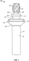
FIG. 1 is a side elevational view of a fastener in accordance with an embodiment of the present invention; -
FIG. 2 is a top elevational view of an embodiment of a seal element employed by the fastener shown inFIG. 1 ; -
FIG. 3 is a side elevational view of the seal element shown inFIG. 2 ; -
FIG. 4 is a partial cross-sectional perspective view of the fastener shown inFIG. 1 , with the fastener installed in a plurality of work pieces; -
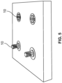
FIG. 5 is a top perspective view of a plurality of the fasteners shown inFIG. 1 , with some being shown in a preinstalled position within a work piece, and some being shown in an installed position within the work piece; -
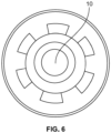
FIG. 6 is a top plan view of the fastener shown inFIG. 1 as installed; -
FIG. 7 is a side elevational view of another embodiment of a fastener having a conforming seal element; -
FIG. 8 is a side elevational view of another embodiment of a fastener having a pin member with selected surfaces coated with a material, and a seal element assembled with the pin member; -
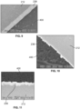
FIGS. 9 through 11 are micro-photographs that illustrate the fastener shown inFIG 8 installed in a structure; -
FIGS. 12A and 12B are schematic illustrations of the fastener ofFIG. 8 before and after a sanding/shaving step, respectively; and -
FIGS. 13 and 14 are photographs of the fastener ofFIG. 8 without and with the seal element, respectively, installed in a structure having a copper mesh layer thereon. - Referring to
FIGS. 1 and4 , afastener 10 is adapted to secure a plurality ofwork pieces fastener 10 is a blind bolt fastener. Thefastener 10 includes acore bolt 12 and asleeve 14 that is sized and shaped to receive thecore bolt 12. Thesleeve 14 includes anelongated portion 15 and ahead 16 positioned at one end thereof. Thehead 16 includes afirst surface 18 having acentral opening 17 that is sized and shaped to receive thecore bolt 12, and abearing surface 19 opposite the first surface 18 (the underside of the head 16). In an embodiment, thecore bolt 12 includes a plurality ofrecesses 20 that is positioned circumferentially on thefirst surface 18 of thehead 16 of thesleeve 14 and around thecentral opening 17 of the sleeve 14 (seeFIG. 4 ). In an embodiment, therecesses 20 are adapted to be engaged by mating features located on one end of a fastener installation tool (not shown in the Figures). Theelongated portion 15 of thesleeve 14 includes an internal threaded portion 21 (seeFIG. 4 ). - Still referring to
FIGS. 1 and4 , thecore bolt 12 includes anelongated shank 22 having a first end and a second end opposite the first end, and which is sized and shaped to extend through thesleeve 14. Thesleeve 14 is sized and shaped to be inserted within openings of thework pieces shank 22 of thecore bolt 12 includes a smoothcylindrical portion 24 and a threadedportion 26 located at the second end of theshank 22. In an embodiment, the threadedportion 26 of theshank 22 includes a diameter that is less than a diameter of the smoothcylindrical portion 24 of theshank 22. The threadedportion 26 of thecore bolt 12 is adapted to engage threadedly the threadedportion 21 of thesleeve 14. Thecore bolt 12 includes afirst head 28 located at the first end of theshank 22 and adjacent to the smoothcylindrical portion 24. In an embodiment, thehead 28 is frustoconical in shape. In an embodiment, adjacent to thehead 28 and also forming a portion of thecore bolt 12 is a frangible,second head 32 having splines or threads 34 (seeFIG. 1 ) that are engageable by a suitable driver attached to an installation tool (not shown in the Figures). In an embodiment, the first andsecond heads second heads portion 36 that defines the weakest point of thecore bolt 12 and is adapted to fracture in torsional shear in response to the rotational force applied tosecond head 32 after thefastener 10 has been set. - In certain embodiments, the
core bolt 12 and thesleeve 14 are similar in structure and function to those corresponding elements disclosed in either (1)U.S. Patent No. 7,308,842 to Hufnagl et al., issued on December 18, 2007 to Huck International, Inc. and entitled Blind Fastener and Nose Assembly for Installation of the Blind Fastener, or (2)U.S. Patent Application Publication No. 2016/0215804 to Hufnagl et al., published on July 28, 2016 in the name of Arconic Inc. entitled Blind Fasteners, the entireties of which are incorporated by reference herein and made a part hereof. - Referring to
FIGS. 1 through 3 , a conformingseal element 38 is attached to theelongated portion 15 of thesleeve 14 and juxtaposed with the bearingsurface 19 of thehead 16 of thesleeve 14. In an embodiment, theseal element 38 is separate and distinct from thesleeve 14. In an embodiment, theseal element 38 is positioned within a hole of thework piece 100 and thesleeve 14 can then be inserted into and contact theseal element 38 during installation of thefastener 10. In an embodiment, theseal element 38 is frusto-conical in shape and includes a centrally located, circular-shapedaperture 40 that is sized and shaped to fit around theelongated portion 15 of thesleeve 14 and juxtaposed with the bearingsurface 19 of thehead 16 of thesleeve 14. In an embodiment, theseal element 38 includes a sealingportion 42. In an embodiment, the sealingportion 42 is frusto-conical in shape. In another embodiment, alip 44 extends from one side of the sealingportion 42. In an embodiment, thelip 44 is angled upwardly from the sealingportion 42. In an embodiment, thelip 44 is angled obliquely from the sealingportion 42. In another embodiment, atubular portion 46 extends axially from an opposite side of the sealing portion 42 (i.e., opposite the lip 44). In an embodiment, thetubular portion 46 includes a length that is very short relative to overall length of theseal element 38. In an embodiment, theseal element 38 is made from copper. In an embodiment, the sealingportion 42 of theseal element 38 has a thickness in a range of about 5 microns to about 100 microns. - In certain embodiments, the
seal element 38 is identical or similar in structure and function to those corresponding elements disclosed inU.S. Patent Application Publication No. 2016/0281760 to Kamal et al., published on September 29, 2016 , entitled COATED FASTENERS WITH CONFORMING SEALS, the entirety of which is incorporated by reference herein and made a part hereof. - Referring to
FIG. 4 , in an embodiment, thefastener 10 includes aninsert 48. In an embodiment, internal threads of theinsert 48 receive and engage threadedly the threadedportion 26 of thecore bolt 12. In an embodiment, theinsert 48 is formed from a material that has lubricating properties. In an embodiment, theinsert 48 includes copper. In other embodiments, theinsert 48 may include other materials (e.g., other metals, plastics, etc.) that have frictional properties suitable to prevent thread galling and that are sufficiently malleable to aid in bulb formation of thesleeve 14. In certain embodiments, theinsert 48 is similar in structure and function to those corresponding elements disclosed in the aforementionedU.S. Patent Application Publication No. 2016/0215804 to Hufnagl , the entirety of which is incorporated by reference herein and made a part hereof. In an embodiment, theelongated portion 15 of thesleeve 14 includes a band annealed portion to facilitate bulb formation of thesleeve 14. In an embodiment, the band annealed portion is located proximate to theinsert 48. In an embodiment, thefastener 10 does not include theinsert 48 and the band annealed portion facilitates bulb formation of thesleeve 14. - In an embodiment, a rotary installation tool having a nose assembly (not shown in the Figures) is provided to set the
fastener 10. In an embodiment, the splines orthreads 34 of thesecond head 32 of thecore bolt 12 are engaged with complementary splines or threads of a driver of the tool (not shown in the Figures). As indicated above, therecesses 20 are adapted to be engaged by mating features positioned on one end of the fastener installation tool. - Rotation of the
core bolt 12 with respect to thesleeve 14 compresses theinsert 48. Theinsert 48 deforms outwardly (i.e., away from the core bolt 12) and thesleeve 14 deforms correspondingly. Such deformation of theinsert 48 and thesleeve 14 causes the formation of a bulb 50 (seeFIG. 4 ). Thework pieces bulb 50 on the blind side of thework piece 102 and thehead 16 of thesleeve 14 on the side of thework piece 100 that is accessible by the installation tool. During installation, a torsional load builds up in thecore bolt 12 and the break neck groove orportion 36 will fracture in torsional or rotational shear and thesecond head 32 will break off at thebreakneck groove 36, as shown, and thefirst head 28 of thecore bolt 12 will be flush, or substantially flush, with thehead 16 of thesleeve 14, and, particularly, thefirst surface 18 of thehead 16, as shown inFIG. 4 . In addition, theseal element 38 is adapted to maximize the true area of contact between the fastener 10 (e.g., the bearingsurface 19 of thehead 16 of the sleeve 14) and thework piece 100 with minimum mechanical load. In an embodiment, thework pieces work pieces work pieces work pieces work pieces work pieces - In an embodiment, the conforming
seal element 38 includes a multi-layer construction with a relatively soft, yet highly electrically conductive base layer, which provides macroscopic conformity, and a softer top layer, which provides microscopic conformity. -
FIG. 5 shows a plurality of thefasteners 10, two of which are shown on the left in a preinstalled position within a work piece, and two of which are shown on the right in an installed position within the work piece.FIG. 6 shows thefastener 10 installed within a work piece and after a shaving step to smooth the remnants of the broken offportion 36 as a result of removal of thehead 32. -
FIG. 7 shows an embodiment of afastener 110 having apin member 112 with a conformingseal element 138. Further details of the structure of thepin member 112 and theseal element 138 are described in aforementioned and incorporatedU.S. Patent Application Publication No. 2016/0281760 to Kamal et al. FIG. 8 shows another embodiment of afastener 210 having apin member 212 with selected surfaces coated with a material, and aseal element 238 assembled with thepin member 212. Further details of the structure of thepin member 212 and theseal element 238 in aforementioned and incorporatedU.S. Patent Application Publication No. 2016/0281760 to Kamal et al. -
FIGS. 9 through 11 are micro-photographs that illustrate thepin member 212 and theseal element 238 shown inFIG 8 installed in astructure 400. Theseal element 238 is adapted to maximize the true area of contact between the fastener (e.g., the bearing surface of the head of the pin member 212) and thestructure 400 with minimum mechanical load. -
FIGS. 12A and 12B are schematic illustrations of the installedfastener 210 ofFIG. 8 before and after a sanding step, respectively, whileFIGS. 13 and 14 are photographs of the installedfastener 210 ofFIG. 8 without and with theseal element 238, respectively, in a structure with copper mesh 500. The method of installation, including the sanding steps, is discussed in further detail in aforementioned and incorporatedU.S. Patent Application Publication No. 2016/0281760 to Kamal et al. - In an embodiment, the
fasteners fasteners fasteners fasteners seal elements fasteners - Although the
fasteners fasteners FIGS. 12A and 12B and 13 and 14). Since fastener holes have substantial geometrical variation and the axial position of thefasteners seal elements fasteners - In an embodiment, the changes in the physics of the fastener interface region results in improved electromagnetic properties. In an embodiment, the
fasteners fastener 10, thedeformable insert 48 forces thesleeve 14 to expand radially to form thebulb 50, thus establishing electrical connection with the inner surface of the structure. In an embodiment, the electrical contact of thefastener 10 effectively reduces the potential difference between thefastener head 16 and the region of contact between thebulb 50 and the structure (e.g., workpiece 102), which not only improves the current and electric field response, but provides a direct path for continuous propagation of electromagnetic waves. Thus, thefastener 10 significantly reduces the internal electrical discontinuities and minimizes floating surfaces and edges within thefastener 10, thus, reducing electromagnetic wave scattering (reduced radar cross section) and minimizing the electromagnetic signature. - Also, the
fastener 10 creates an intimate electrical bond that penetrates deeper into the structure along the entire surface under the fastener head (e.g., thehead 16 of thesleeve 14 and the seal element 38), which again reduces the potential for electromagnetic wave scattering form subsurface discontinuities. The integrity of the electrical path is exceptional using thefastener 10 and its uniform surface characteristics result in an enhanced aerodynamic paint surface which is highly desired. - It should be understood that the embodiments described herein are merely exemplary and that a person skilled in the art may make many variations and modifications without departing from the scope of the invention. All such variations and modifications are intended to be included within the scope of the invention as exemplified by the appended claims.
Claims (15)
- A fastener (10), comprising:a sleeve (14) having an elongated portion (15) having a first end and a second end opposite the first end, a head (16) located at the first end of the elongated portion, and an internal threaded portion (21) located at the second end of the elongated portion, the head including a bearing surface (19) located on an underside thereof;a core bolt (12) disposed within the sleeve and having a first end, a second end opposite the first end of the core bolt, a head (28) located at the first end of the core bolt, and a shank portion (22) having an external threaded portion (26) located proximate to the second end of the core bolt, the threaded portion of the core bolt being engageable threadedly with the threaded portion of the sleeve; andcharacterized by a seal element (38) attached to the sleeve and juxtaposed with the bearing surface of the head of the sleeve.
- The fastener (10) of claim 1, wherein the seal element (38) is made of copper.
- The fastener (10) of claim 1 or claim 2, wherein the seal element (38) includes a sealing portion (42) and a lip (44) that extends angularly from the sealing portion, and preferablywherein the seal element includes a tubular portion (46) extending axially from the sealing portion, and more preferablywherein the sealing portion of the seal element includes a thickness in a range of about 5 microns to about 100 microns.
- The fastener (10) of any preceding claim, further comprising an insert (48) disposed within the sleeve (14) and surrounding a portion of the core bolt (12).
- The fastener (10) of claim 4, wherein the elongated portion (15) of the sleeve (14) includes a band annealed portion proximate to the insert (48).
- The fastener (10) of claim 4 or claim 5, wherein the insert (48) includes a tubular member having internal threads that are engageable threadedly with the threaded portion (26) of the core bolt (12).
- The fastener (10) of claim 4 or claim 5, wherein the insert (48) includes a coil spring having a trapezoidal cross-section and coiled around and within the threaded portion (26) of the core bolt (12).
- The fastener (10) of any preceding claim, wherein the head (28) of the core bolt (12) includes a flush head, and preferably
wherein the head (16) of the sleeve (14) is sized and shaped to receive the flush head of the core bolt. - The fastener (10) of any preceding claim, wherein the core bolt (12) includes a second head (32) attached removably to the head (28) of the core bolt, the second head being adapted to be engaged by a fastener installation tool.
- A combination of the fastener (10) of any preceding claim and a structure, wherein the fastener is installed within the structure.
- The combination of claim 10, wherein the structure includes a composite material, and preferablywherein the structure is substantially made from the composite material, orthe structure is partially made from the composite material.
- The combination of claim 10 or claim 11, wherein the structure includes a metallic material.
- The combination of claim 12, wherein the metallic material is aluminum.
- The combination of claim 12 or claim 13, wherein the structure is made substantially from the metallic material, or
wherein the structure is made partially from the metallic material. - The combination of any of claims 10 to 14, wherein the structure includes a metallic mesh on an outer surface of the structure, wherein when the fastener is in its installed position, the sealing element of the fastener is in direct physical and electrical contact with the metallic mesh, and preferably
wherein the metallic mesh is made from copper and the seal element is made from copper.
Applications Claiming Priority (2)
| Application Number | Priority Date | Filing Date | Title |
|---|---|---|---|
| US201662433545P | 2016-12-13 | 2016-12-13 | |
| PCT/US2017/065356 WO2018111723A1 (en) | 2016-12-13 | 2017-12-08 | Reduced electromagnetic signature of conforming conical seal fastener systems |
Publications (3)
| Publication Number | Publication Date |
|---|---|
| EP3555488A1 EP3555488A1 (en) | 2019-10-23 |
| EP3555488A4 EP3555488A4 (en) | 2020-06-10 |
| EP3555488B1 true EP3555488B1 (en) | 2023-04-12 |
Family
ID=62488425
Family Applications (1)
| Application Number | Title | Priority Date | Filing Date |
|---|---|---|---|
| EP17880503.2A Active EP3555488B1 (en) | 2016-12-13 | 2017-12-08 | Reduced electromagnetic signature of conforming conical seal fastener systems |
Country Status (7)
| Country | Link |
|---|---|
| US (1) | US10457414B2 (en) |
| EP (1) | EP3555488B1 (en) |
| JP (1) | JP6852176B2 (en) |
| CN (2) | CN108612721A (en) |
| CA (1) | CA3038357C (en) |
| ES (1) | ES2942887T3 (en) |
| WO (1) | WO2018111723A1 (en) |
Families Citing this family (10)
| Publication number | Priority date | Publication date | Assignee | Title |
|---|---|---|---|---|
| US9939004B2 (en) * | 2014-09-17 | 2018-04-10 | Arconic Inc | Coated fasteners with conforming seals |
| US11396900B2 (en) | 2019-05-10 | 2022-07-26 | The Boeing Company | Fastener and methods of manufacturing and use |
| USD928602S1 (en) * | 2019-06-07 | 2021-08-24 | Sps Technologies, Llc | Blind fastener bolt |
| USD920774S1 (en) * | 2019-08-27 | 2021-06-01 | Sps Technologies, Llc | Blind fastener |
| USD935877S1 (en) * | 2019-08-27 | 2021-11-16 | Sps Technologies, Llc | Blind fastener nut |
| US11879488B2 (en) * | 2020-01-13 | 2024-01-23 | The Boeing Company | Lightning damage resistant one sided installation |
| US12601366B2 (en) | 2020-06-16 | 2026-04-14 | Howmet Aerospace Inc. | Fluid tight blind fasteners and methods for fastening |
| US12473941B2 (en) | 2020-08-07 | 2025-11-18 | Peri Se | Multi-head bolt and fastener system |
| CN114658740A (en) * | 2022-04-13 | 2022-06-24 | 江苏观远新材料有限公司 | A front-adjustable assembled "dry" type leveling bolt and installation method |
| WO2024155417A1 (en) * | 2023-01-17 | 2024-07-25 | Howmet Aerospace Inc. | Blind fastener |
Family Cites Families (122)
| Publication number | Priority date | Publication date | Assignee | Title |
|---|---|---|---|---|
| US1868415A (en) | 1929-10-31 | 1932-07-19 | Gundersen Einar | Method of manufacturing screws with one or two appending washers |
| US2353531A (en) * | 1943-05-03 | 1944-07-11 | David B Whitney | Cap screw |
| US2396661A (en) | 1944-01-15 | 1946-03-19 | North American Aviation Inc | Securing device |
| US2501567A (en) | 1944-05-19 | 1950-03-21 | Huck Mfg Co | Rivet |
| US2940767A (en) | 1955-10-04 | 1960-06-14 | Yale & Towne Mfg Co | Light duty hydraulic truck |
| US2868056A (en) * | 1955-10-20 | 1959-01-13 | Torre Albert J La | Blind fastener having expansible coil spring head |
| US3215024A (en) | 1957-07-11 | 1965-11-02 | Huck Mfg Co | Fastener |
| US3041912A (en) | 1958-11-25 | 1962-07-03 | Shur Lok Corp | Honeycomb spacer stud and interlocking grommet |
| US3136203A (en) * | 1960-11-29 | 1964-06-09 | Gen Dynamics Corp | Blind rivet having means for retaining the expansion bolt |
| US3271058A (en) | 1963-05-22 | 1966-09-06 | Anderson Greenwood & Co | Tapered fastener |
| US3239036A (en) | 1963-05-28 | 1966-03-08 | Vsi Corp | High pressure sealing-type fastener |
| US3304109A (en) | 1965-04-21 | 1967-02-14 | Hi Shear Corp | Joint including tapered fastener |
| US3464306A (en) * | 1967-12-14 | 1969-09-02 | Huck Mfg Co | Combination sealant relief groove in collar |
| US3606357A (en) | 1968-06-24 | 1971-09-20 | John L Yonkers | Self-sealing and aligning member |
| US3953906A (en) | 1968-10-03 | 1976-05-04 | Brown Clarence K | Fastener assembly |
| US3535911A (en) | 1968-12-20 | 1970-10-27 | Boeing Co | Friction test method and apparatus |
| US4102030A (en) | 1970-04-30 | 1978-07-25 | King John O Jun | Method of forming a sealing sleeve joint construction |
| US3835615A (en) | 1970-04-30 | 1974-09-17 | J King | Fastener joint construction |
| CA957188A (en) | 1971-12-15 | 1974-11-05 | Jacob M. Hage | Screw threaded fastening means and like products |
| US3792933A (en) | 1971-12-20 | 1974-02-19 | Vsi Corp | High-strength fastening system |
| US3788185A (en) | 1972-02-01 | 1974-01-29 | Elco Industries Inc | Controlled-drive sealing fastener |
| US3820297A (en) | 1972-11-10 | 1974-06-28 | Huck Mfg Co | Interference fit blind fastener |
| US4164807A (en) | 1974-03-19 | 1979-08-21 | King John O Jun | Method of forming a coldworked joint |
| US3949535A (en) | 1973-01-17 | 1976-04-13 | King John O Jun | Coldworked joint held by seamless tubular member |
| US3915052A (en) | 1974-08-22 | 1975-10-28 | Huck Mfg Co | Self broaching fastener assembly and like self sizing fasteners |
| US4048898A (en) | 1974-10-17 | 1977-09-20 | Paul R. Briles | Fastener for multi metal stack-ups |
| US3965792A (en) | 1975-01-17 | 1976-06-29 | King John O Jun | Split pintail fastener assembly |
| US4164971A (en) | 1976-11-01 | 1979-08-21 | Federal Screw Works | Threaded fastener product with adhesive coating |
| US4114505A (en) | 1977-01-31 | 1978-09-19 | Loeser William J | Coatings and methods of application |
| US4244661A (en) | 1979-07-23 | 1981-01-13 | Mcdonnell Douglas Corporation | Fastener means and joint for laminates |
| US4472097A (en) | 1981-03-20 | 1984-09-18 | Farathane, Inc. | Torque limiting elastomeric fastener and seal |
| US4405256A (en) | 1981-04-14 | 1983-09-20 | King John O Jun | Cushioned fastener joint |
| US4502092A (en) | 1982-09-30 | 1985-02-26 | The Boeing Company | Integral lightning protection system for composite aircraft skins |
| US4479163A (en) | 1982-09-30 | 1984-10-23 | The Boeing Company | Integral lightning protection system for composite aircraft skins |
| US4557033A (en) | 1983-07-11 | 1985-12-10 | Fatigue Technology, Inc. | Method of cold expanding and sizing fastener holes |
| US4609315A (en) * | 1984-03-19 | 1986-09-02 | Briles Franklin S | Corrosion resistant dual tapered head fastener and panel composite |
| US4867625A (en) | 1985-04-29 | 1989-09-19 | Huck Manufacturing Company | Variable clamp fastener and method |
| US4789283A (en) | 1985-07-02 | 1988-12-06 | Pavco Industries, Inc. | Fluid-tight blind rivet |
| US4813834A (en) | 1985-08-01 | 1989-03-21 | Huck Manufacturing Company | Fit-up fastener with flexible tab-like retaining structure and method of making same |
| US4702655A (en) | 1985-08-27 | 1987-10-27 | Huck Manufacturing Company | Fastening system including an improved interference fit blind fastener and method of manufacture |
| US4628402A (en) | 1985-09-30 | 1986-12-09 | The Boeing Company | Lightning protection of fasteners in composite material |
| US4760493A (en) | 1985-09-30 | 1988-07-26 | The Boeing Company | Lightning protection system for composite material aircraft structures |
| US4850771A (en) | 1986-04-01 | 1989-07-25 | Hurd Ramon L | Installation system for securing workpieces of composite materials and the like and threaded fastener for such system |
| IL81917A (en) | 1986-04-01 | 1992-01-15 | Huck Mfg Co | Threaded fastener for securing together workpieces of composite materials and the like |
| US4755904A (en) | 1986-06-06 | 1988-07-05 | The Boeing Company | Lightning protection system for conductive composite material structure |
| JPH0542252Y2 (en) * | 1986-11-11 | 1993-10-25 | ||
| GB8628555D0 (en) | 1986-11-28 | 1987-01-07 | British Aerospace | Anti lightning strike fasteners |
| US4943196A (en) | 1987-08-20 | 1990-07-24 | Sps Technologies, Inc. | Swaged collar fastener |
| GB2212580B (en) | 1987-11-14 | 1992-03-25 | British Aerospace | Methods of fastening composite aircraft skins |
| US4905931A (en) | 1988-02-18 | 1990-03-06 | The Boeing Company | Arc suppression around fasteners |
| US5018920A (en) | 1989-01-23 | 1991-05-28 | Mcdonnell Douglas Corporation | Interference fit bolt and sleeve |
| US5129253A (en) | 1990-01-26 | 1992-07-14 | Bell Helicopter Textron Inc. | Antifretting coating for a bushing in a coldworked joint |
| US5083363A (en) | 1990-07-25 | 1992-01-28 | Fatigue Technology, Inc. | Method of installing a grommet in a wall of composite material |
| DE4116149A1 (en) | 1991-05-17 | 1992-11-19 | Hilti Ag | SPREADING DOWEL WITH FRICTION REDUCING COATING |
| US5391028A (en) | 1993-05-12 | 1995-02-21 | Northrop Grumman Corporation | Method for reducing radar cross-section of aircraft fasteners, and fastener assemblies for use therein |
| JPH0851111A (en) | 1994-08-09 | 1996-02-20 | Kawasaki Steel Corp | Semiconductor device and manufacturing method thereof |
| USD372857S (en) | 1994-10-11 | 1996-08-20 | Huck International, Inc. | Bolt and nut assembly |
| US6036418A (en) * | 1998-08-12 | 2000-03-14 | Monogram Aerospace Fasteners, Inc. | Self-expanding blind fastener with mechanical lock |
| US6149363A (en) | 1998-10-29 | 2000-11-21 | Huck International, Inc. | Lightweight threaded fastener and thread rolling die |
| GB2344864A (en) * | 1998-12-17 | 2000-06-21 | Textron Fastening Syst Ltd | Blind fastener |
| US6315485B1 (en) | 1999-08-13 | 2001-11-13 | Northrop Grumman Corporation | Low observable aircraft fastener treatment |
| US6213699B1 (en) | 1999-09-10 | 2001-04-10 | Huck International, Inc. | Filling rivet with high pin lock |
| US6589918B2 (en) | 2000-06-22 | 2003-07-08 | Nsk Ltd. | Conductive grease and rolling apparatus packed with the same |
| DE10107952C1 (en) | 2001-02-20 | 2002-04-04 | Airbus Gmbh | Locking ring bolt, for sealed mechanical connection, has profiled locking region of bolt shaft provided with diamond profiles for distribution of sealing mass |
| US6679667B2 (en) | 2001-02-28 | 2004-01-20 | Northrop Grumman Corporation | Hot melt fastener filler |
| US6499926B2 (en) | 2001-05-18 | 2002-12-31 | The Boeing Company | Fastener apparatus and method of fastening non-metallic structures |
| US6665922B2 (en) | 2002-05-13 | 2003-12-23 | Hi-Shear Corporation | Pull stem hi-lite pin with pull groove for swaging collars |
| DE20210801U1 (en) | 2002-05-21 | 2002-10-24 | Holler, Wilhelm F., 92318 Neumarkt | Connection element for a tight and / or adhesive connection |
| US6868757B2 (en) * | 2003-05-20 | 2005-03-22 | Huck International, Inc. | Blind fastener and nose assembly for installation of the blind fastener |
| EP1628879B1 (en) | 2003-05-30 | 2006-09-20 | BAE Systems PLC | Composite structure lightning protection |
| ES2264299B1 (en) | 2003-06-06 | 2007-11-16 | Airbus España S.L. | LIGHTNING PROTECTION SYSTEM FOR FUEL TANKS MANUFACTURED IN POOR ELECTRICAL CONDUCTIVITY MATERIALS. |
| US7038920B2 (en) | 2003-06-30 | 2006-05-02 | Intel Corporation | System to mount electrical modules |
| GB0329891D0 (en) | 2003-12-23 | 2004-01-28 | Airbus Uk Ltd | A sealing material |
| US7554785B2 (en) | 2004-03-23 | 2009-06-30 | The Boeing Company | Lightning damage protection for composite aircraft |
| US7236343B2 (en) | 2005-01-05 | 2007-06-26 | The Boeing Company | Method and system for lightning current conduction protection using foil bonded strips |
| EP1712659A1 (en) | 2005-04-11 | 2006-10-18 | Elisha Holding LLC | Corrosion resistant article and method of production thereof |
| JP4729977B2 (en) | 2005-05-17 | 2011-07-20 | 株式会社ケンウッド | Waterproof structure for fastening parts with screws |
| US7633283B2 (en) | 2005-07-01 | 2009-12-15 | The Boeing Company | Method for lightning strike protection and verification of magnetizable dielectric inserts |
| US7755876B2 (en) | 2005-07-01 | 2010-07-13 | The Boeing Company | Fastening assembly including washer for sealing the assembly for lightning strike protection in composite structures |
| US7721990B2 (en) | 2005-07-29 | 2010-05-25 | Airbus Deutschland Gmbh | Passenger compartment |
| US7521402B2 (en) | 2005-08-22 | 2009-04-21 | Nd Industries, Inc. | Lubricant composition, fastener coated with same, and methods for making and using same |
| US7326015B2 (en) | 2005-08-30 | 2008-02-05 | Hydril Company Llc | Electrically insulated wedge thread connection |
| US7686905B2 (en) | 2005-09-06 | 2010-03-30 | The Boeing Company | Copper grid repair technique for lightning strike protection |
| US7277266B1 (en) | 2006-03-29 | 2007-10-02 | The Boeing Company | Lightning protection system for composite structure |
| US7869181B2 (en) | 2006-03-29 | 2011-01-11 | The Boeing Company | Flex circuit lightning protection applique system for skin fasteners in composite structures |
| US7695226B2 (en) | 2006-09-21 | 2010-04-13 | Alcoa Global Fasteners, Inc. | High performance sleeved interference fasteners for composite applications |
| US7599164B2 (en) | 2006-12-07 | 2009-10-06 | The Boeing Company | Lightning protection system for aircraft composite structure |
| US7898785B2 (en) | 2006-12-07 | 2011-03-01 | The Boeing Company | Lightning protection system for an aircraft composite structure |
| US7525785B2 (en) | 2006-12-14 | 2009-04-28 | The Boeing Company | Lightning strike protection method and apparatus |
| US7738236B2 (en) | 2007-01-12 | 2010-06-15 | The Boeing Company | Light weight system for lightning protection of nonconductive aircraft panels |
| JP5242920B2 (en) | 2007-01-23 | 2013-07-24 | 株式会社日立製作所 | Split blade for windmill |
| US20090053006A1 (en) * | 2007-08-20 | 2009-02-26 | Alcoa Global Fasteners, Inc. | Blind fastener and nose assembly for installation thereof |
| US8047749B2 (en) | 2007-08-30 | 2011-11-01 | The Boeing Company | Rapid inspection of lightning strike protection systems prior to installing fastener |
| WO2009052325A1 (en) | 2007-10-16 | 2009-04-23 | Fatigue Technology, Inc. | Expandable fastener assembly with deformed collar |
| ES2334735B1 (en) | 2007-11-15 | 2011-01-26 | Airbus España S.L. | PROTECTIVE DEVICE AGAINST ELECTRIC SHOCK IN DEFIJEMENT ELEMENTS. |
| FR2924687B1 (en) | 2007-12-11 | 2010-05-07 | Airbus France | AIRCRAFT AND AIRCRAFT SYSTEM COMPRISING SUCH A SYSTEM |
| FR2924685B1 (en) | 2007-12-11 | 2010-03-19 | Airbus France | PARAFOUDRE AND AIRCRAFT SYSTEM COMPRISING SUCH A SYSTEM. |
| FR2924686B1 (en) | 2007-12-11 | 2010-05-14 | Airbus France | PARAFOUDRE AND AIRCRAFT SYSTEM COMPRISING SUCH A SYSTEM. |
| US8382413B2 (en) | 2008-11-17 | 2013-02-26 | The Boeing Company | Conductive sleeved fastener assembly |
| JP2010133446A (en) | 2008-12-02 | 2010-06-17 | Hisao Ishii | Screw and fastening structure using the screw |
| ES2376323B1 (en) | 2009-02-27 | 2013-01-24 | Airbus Operations, S.L. | IMPROVEMENT OF PROTECTION AGAINST DIRECT IMPACT OF RAYS IN RIVED PANEL AREAS IN CFRP. |
| US9562556B2 (en) * | 2009-04-03 | 2017-02-07 | Arconic Inc. | Fasteners with conforming sleeves |
| US8322958B2 (en) | 2009-04-03 | 2012-12-04 | Alcoa Inc. | Fasteners with conforming sleeves |
| EP2417369B1 (en) | 2009-04-10 | 2014-04-02 | Fatigue Technology, Inc. | Installable assembly having an expandable outer member and a fastener with a mandrel |
| KR101420155B1 (en) * | 2009-10-22 | 2014-07-16 | 알코아 인코포레이티드 | Enhanced conductivity sleeved fastener and method for making same |
| EP2513499B1 (en) | 2009-12-16 | 2015-04-08 | Fatigue Technology, Inc. | Modular nut plate assemblies and methods of using the same |
| DE102010009901B4 (en) | 2010-03-02 | 2017-11-02 | Aktiebolaget Skf | Rolling bearing cage |
| US8647036B2 (en) | 2010-06-14 | 2014-02-11 | Alcoa Inc. | Retainer ring |
| JP5473892B2 (en) | 2010-12-28 | 2014-04-16 | 三菱航空機株式会社 | Lightning-resistant fasteners, aircraft |
| GB201110939D0 (en) | 2011-06-28 | 2011-08-10 | Rolls Royce Plc | A coated fastener |
| DE102012100228A1 (en) | 2012-01-12 | 2013-07-18 | Kamax Holding Gmbh & Co. Kg | Screw with a head support surface with lubricant pockets |
| ES2645622T3 (en) * | 2012-04-17 | 2017-12-07 | Arconic Inc. | Blind Fixation Device |
| US8979453B2 (en) * | 2012-04-17 | 2015-03-17 | Alcoa Inc. | Blind fastener |
| DE102013000308A1 (en) | 2013-01-10 | 2014-07-10 | Daimler Ag | Corrosion-protected connection arrangement for connecting electrochemical noble material component and tensioning belt in exhaust gas system of motor vehicle, has separation layer whose surface is coated with metal oxide layer |
| US9169862B2 (en) | 2013-02-19 | 2015-10-27 | The Boeing Company | Self-aligning sleeved protruding head fasteners with electromagnetic effect protection features |
| CN203297273U (en) | 2013-04-26 | 2013-11-20 | 广州豹驰汽配有限公司 | Bolt used for fixing automobile wheel |
| US9291187B2 (en) | 2013-05-20 | 2016-03-22 | The Boeing Company | Nut, washer and fastener head for electromagnetic effect protection |
| US9123998B1 (en) | 2014-03-04 | 2015-09-01 | The Boeing Company | Lightning protected radome system |
| BR112017005059A2 (en) | 2014-09-17 | 2017-12-05 | Arconic Inc | fasteners with textured and coated pin elements |
| US9939004B2 (en) * | 2014-09-17 | 2018-04-10 | Arconic Inc | Coated fasteners with conforming seals |
| EP3194799A1 (en) * | 2014-09-17 | 2017-07-26 | Arconic Inc. | Fasteners with dual skin depth washers |
| US10006478B2 (en) * | 2015-01-22 | 2018-06-26 | Arconic Inc. | Blind fasteners |
-
2017
- 2017-12-08 JP JP2019545908A patent/JP6852176B2/en active Active
- 2017-12-08 EP EP17880503.2A patent/EP3555488B1/en active Active
- 2017-12-08 US US15/836,296 patent/US10457414B2/en active Active
- 2017-12-08 ES ES17880503T patent/ES2942887T3/en active Active
- 2017-12-08 WO PCT/US2017/065356 patent/WO2018111723A1/en not_active Ceased
- 2017-12-08 CA CA3038357A patent/CA3038357C/en active Active
- 2017-12-13 CN CN201711337181.7A patent/CN108612721A/en active Pending
- 2017-12-13 CN CN201721742267.3U patent/CN208089719U/en active Active
Also Published As
| Publication number | Publication date |
|---|---|
| ES2942887T3 (en) | 2023-06-07 |
| WO2018111723A1 (en) | 2018-06-21 |
| CA3038357C (en) | 2022-03-15 |
| CN108612721A (en) | 2018-10-02 |
| CA3038357A1 (en) | 2018-06-21 |
| BR112019010224A2 (en) | 2019-08-27 |
| JP2019535985A (en) | 2019-12-12 |
| US10457414B2 (en) | 2019-10-29 |
| EP3555488A1 (en) | 2019-10-23 |
| US20180162551A1 (en) | 2018-06-14 |
| CN208089719U (en) | 2018-11-13 |
| EP3555488A4 (en) | 2020-06-10 |
| JP6852176B2 (en) | 2021-03-31 |
Similar Documents
| Publication | Publication Date | Title |
|---|---|---|
| US10457414B2 (en) | Reduced electromagnetic signature of conforming conical seal fastener systems | |
| EP3584289B1 (en) | Blind fastener system with electromagnetic effects-protective coating | |
| EP2947015B1 (en) | Modified shank fasteners for electromagnetic effect (eme) technology | |
| EP3194798B1 (en) | Fasteners with coated and textured pin members | |
| US9669942B2 (en) | Lightning damage resistant aircraft skin fasteners | |
| CN113153882B (en) | Apparatus and method for conductively coated fastening systems | |
| KR20080027210A (en) | High-performance, sleeve-fit fit fasteners for composite applications | |
| JP2013508646A (en) | Fastener with sleeve having improved electrical conductivity and method for producing the same | |
| CN108488192A (en) | A kind of spindle-type riveting nut and preparation method thereof | |
| US20160240939A1 (en) | Conductive sleeved fastener assembly | |
| US9702396B2 (en) | Fasteners with dual skin depth washers | |
| US9939004B2 (en) | Coated fasteners with conforming seals | |
| WO2014120362A1 (en) | Sleeved fastener assembly | |
| US20160068275A1 (en) | Locking member with sealing insert and channel | |
| CN110319098B (en) | Electromagnetic effect shielding fastener with frangible collar | |
| CN110319093B (en) | Electromagnetic effect protective fastener with swageable termination body | |
| EP3341621B1 (en) | Coated fasteners with conforming seals | |
| BR112019010224B1 (en) | FASTENER AND COMBINATION OF A FRAME, A FASTENER, A CENTER SCREW AND A SEALING ELEMENT | |
| CA2954898C (en) | Coated fasteners with conforming seals |
Legal Events
| Date | Code | Title | Description |
|---|---|---|---|
| STAA | Information on the status of an ep patent application or granted ep patent |
Free format text: STATUS: THE INTERNATIONAL PUBLICATION HAS BEEN MADE |
|
| PUAI | Public reference made under article 153(3) epc to a published international application that has entered the european phase |
Free format text: ORIGINAL CODE: 0009012 |
|
| STAA | Information on the status of an ep patent application or granted ep patent |
Free format text: STATUS: REQUEST FOR EXAMINATION WAS MADE |
|
| 17P | Request for examination filed |
Effective date: 20190515 |
|
| AK | Designated contracting states |
Kind code of ref document: A1 Designated state(s): AL AT BE BG CH CY CZ DE DK EE ES FI FR GB GR HR HU IE IS IT LI LT LU LV MC MK MT NL NO PL PT RO RS SE SI SK SM TR |
|
| AX | Request for extension of the european patent |
Extension state: BA ME |
|
| DAV | Request for validation of the european patent (deleted) | ||
| DAX | Request for extension of the european patent (deleted) | ||
| A4 | Supplementary search report drawn up and despatched |
Effective date: 20200511 |
|
| RIC1 | Information provided on ipc code assigned before grant |
Ipc: B64D 45/02 20060101ALI20200504BHEP Ipc: B64C 1/00 20060101ALI20200504BHEP Ipc: F16B 1/00 20060101ALN20200504BHEP Ipc: F16B 35/04 20060101ALN20200504BHEP Ipc: F16B 33/00 20060101AFI20200504BHEP Ipc: F16B 23/00 20060101ALN20200504BHEP Ipc: F16B 5/06 20060101ALN20200504BHEP Ipc: F16B 43/00 20060101ALI20200504BHEP Ipc: F16B 19/10 20060101ALI20200504BHEP |
|
| RAP1 | Party data changed (applicant data changed or rights of an application transferred) |
Owner name: HOWMET AEROSPACE INC. |
|
| STAA | Information on the status of an ep patent application or granted ep patent |
Free format text: STATUS: EXAMINATION IS IN PROGRESS |
|
| 17Q | First examination report despatched |
Effective date: 20220512 |
|
| RIC1 | Information provided on ipc code assigned before grant |
Ipc: F16B 35/04 20060101ALN20221021BHEP Ipc: F16B 1/00 20060101ALN20221021BHEP Ipc: F16B 5/06 20060101ALN20221021BHEP Ipc: F16B 23/00 20060101ALN20221021BHEP Ipc: F16B 43/00 20060101ALI20221021BHEP Ipc: B64C 1/00 20060101ALI20221021BHEP Ipc: B64D 45/02 20060101ALI20221021BHEP Ipc: F16B 19/10 20060101ALI20221021BHEP Ipc: F16B 33/00 20060101AFI20221021BHEP |
|
| RIC1 | Information provided on ipc code assigned before grant |
Ipc: F16B 35/04 20060101ALN20221107BHEP Ipc: F16B 1/00 20060101ALN20221107BHEP Ipc: F16B 5/06 20060101ALN20221107BHEP Ipc: F16B 23/00 20060101ALN20221107BHEP Ipc: F16B 43/00 20060101ALI20221107BHEP Ipc: B64C 1/00 20060101ALI20221107BHEP Ipc: B64D 45/02 20060101ALI20221107BHEP Ipc: F16B 19/10 20060101ALI20221107BHEP Ipc: F16B 33/00 20060101AFI20221107BHEP |
|
| INTG | Intention to grant announced |
Effective date: 20221215 |
|
| GRAS | Grant fee paid |
Free format text: ORIGINAL CODE: EPIDOSNIGR3 |
|
| STAA | Information on the status of an ep patent application or granted ep patent |
Free format text: STATUS: GRANT OF PATENT IS INTENDED |
|
| GRAA | (expected) grant |
Free format text: ORIGINAL CODE: 0009210 |
|
| STAA | Information on the status of an ep patent application or granted ep patent |
Free format text: STATUS: THE PATENT HAS BEEN GRANTED |
|
| AK | Designated contracting states |
Kind code of ref document: B1 Designated state(s): AL AT BE BG CH CY CZ DE DK EE ES FI FR GB GR HR HU IE IS IT LI LT LU LV MC MK MT NL NO PL PT RO RS SE SI SK SM TR |
|
| REG | Reference to a national code |
Ref country code: GB Ref legal event code: FG4D |
|
| REG | Reference to a national code |
Ref country code: CH Ref legal event code: EP |
|
| REG | Reference to a national code |
Ref country code: DE Ref legal event code: R096 Ref document number: 602017067730 Country of ref document: DE |
|
| REG | Reference to a national code |
Ref country code: IE Ref legal event code: FG4D |
|
| REG | Reference to a national code |
Ref country code: AT Ref legal event code: REF Ref document number: 1559937 Country of ref document: AT Kind code of ref document: T Effective date: 20230515 |
|
| REG | Reference to a national code |
Ref country code: ES Ref legal event code: FG2A Ref document number: 2942887 Country of ref document: ES Kind code of ref document: T3 Effective date: 20230607 |
|
| REG | Reference to a national code |
Ref country code: LT Ref legal event code: MG9D |
|
| REG | Reference to a national code |
Ref country code: NL Ref legal event code: MP Effective date: 20230412 |
|
| REG | Reference to a national code |
Ref country code: AT Ref legal event code: MK05 Ref document number: 1559937 Country of ref document: AT Kind code of ref document: T Effective date: 20230412 |
|
| PG25 | Lapsed in a contracting state [announced via postgrant information from national office to epo] |
Ref country code: NL Free format text: LAPSE BECAUSE OF FAILURE TO SUBMIT A TRANSLATION OF THE DESCRIPTION OR TO PAY THE FEE WITHIN THE PRESCRIBED TIME-LIMIT Effective date: 20230412 |
|
| PG25 | Lapsed in a contracting state [announced via postgrant information from national office to epo] |
Ref country code: SE Free format text: LAPSE BECAUSE OF FAILURE TO SUBMIT A TRANSLATION OF THE DESCRIPTION OR TO PAY THE FEE WITHIN THE PRESCRIBED TIME-LIMIT Effective date: 20230412 Ref country code: PT Free format text: LAPSE BECAUSE OF FAILURE TO SUBMIT A TRANSLATION OF THE DESCRIPTION OR TO PAY THE FEE WITHIN THE PRESCRIBED TIME-LIMIT Effective date: 20230814 Ref country code: NO Free format text: LAPSE BECAUSE OF FAILURE TO SUBMIT A TRANSLATION OF THE DESCRIPTION OR TO PAY THE FEE WITHIN THE PRESCRIBED TIME-LIMIT Effective date: 20230712 Ref country code: AT Free format text: LAPSE BECAUSE OF FAILURE TO SUBMIT A TRANSLATION OF THE DESCRIPTION OR TO PAY THE FEE WITHIN THE PRESCRIBED TIME-LIMIT Effective date: 20230412 |
|
| PG25 | Lapsed in a contracting state [announced via postgrant information from national office to epo] |
Ref country code: RS Free format text: LAPSE BECAUSE OF FAILURE TO SUBMIT A TRANSLATION OF THE DESCRIPTION OR TO PAY THE FEE WITHIN THE PRESCRIBED TIME-LIMIT Effective date: 20230412 Ref country code: PL Free format text: LAPSE BECAUSE OF FAILURE TO SUBMIT A TRANSLATION OF THE DESCRIPTION OR TO PAY THE FEE WITHIN THE PRESCRIBED TIME-LIMIT Effective date: 20230412 Ref country code: LV Free format text: LAPSE BECAUSE OF FAILURE TO SUBMIT A TRANSLATION OF THE DESCRIPTION OR TO PAY THE FEE WITHIN THE PRESCRIBED TIME-LIMIT Effective date: 20230412 Ref country code: LT Free format text: LAPSE BECAUSE OF FAILURE TO SUBMIT A TRANSLATION OF THE DESCRIPTION OR TO PAY THE FEE WITHIN THE PRESCRIBED TIME-LIMIT Effective date: 20230412 Ref country code: IS Free format text: LAPSE BECAUSE OF FAILURE TO SUBMIT A TRANSLATION OF THE DESCRIPTION OR TO PAY THE FEE WITHIN THE PRESCRIBED TIME-LIMIT Effective date: 20230812 Ref country code: HR Free format text: LAPSE BECAUSE OF FAILURE TO SUBMIT A TRANSLATION OF THE DESCRIPTION OR TO PAY THE FEE WITHIN THE PRESCRIBED TIME-LIMIT Effective date: 20230412 Ref country code: GR Free format text: LAPSE BECAUSE OF FAILURE TO SUBMIT A TRANSLATION OF THE DESCRIPTION OR TO PAY THE FEE WITHIN THE PRESCRIBED TIME-LIMIT Effective date: 20230713 Ref country code: AL Free format text: LAPSE BECAUSE OF FAILURE TO SUBMIT A TRANSLATION OF THE DESCRIPTION OR TO PAY THE FEE WITHIN THE PRESCRIBED TIME-LIMIT Effective date: 20230412 |
|
| PG25 | Lapsed in a contracting state [announced via postgrant information from national office to epo] |
Ref country code: FI Free format text: LAPSE BECAUSE OF FAILURE TO SUBMIT A TRANSLATION OF THE DESCRIPTION OR TO PAY THE FEE WITHIN THE PRESCRIBED TIME-LIMIT Effective date: 20230412 |
|
| REG | Reference to a national code |
Ref country code: DE Ref legal event code: R097 Ref document number: 602017067730 Country of ref document: DE |
|
| PG25 | Lapsed in a contracting state [announced via postgrant information from national office to epo] |
Ref country code: SK Free format text: LAPSE BECAUSE OF FAILURE TO SUBMIT A TRANSLATION OF THE DESCRIPTION OR TO PAY THE FEE WITHIN THE PRESCRIBED TIME-LIMIT Effective date: 20230412 |
|
| PG25 | Lapsed in a contracting state [announced via postgrant information from national office to epo] |
Ref country code: SM Free format text: LAPSE BECAUSE OF FAILURE TO SUBMIT A TRANSLATION OF THE DESCRIPTION OR TO PAY THE FEE WITHIN THE PRESCRIBED TIME-LIMIT Effective date: 20230412 Ref country code: SK Free format text: LAPSE BECAUSE OF FAILURE TO SUBMIT A TRANSLATION OF THE DESCRIPTION OR TO PAY THE FEE WITHIN THE PRESCRIBED TIME-LIMIT Effective date: 20230412 Ref country code: RO Free format text: LAPSE BECAUSE OF FAILURE TO SUBMIT A TRANSLATION OF THE DESCRIPTION OR TO PAY THE FEE WITHIN THE PRESCRIBED TIME-LIMIT Effective date: 20230412 Ref country code: EE Free format text: LAPSE BECAUSE OF FAILURE TO SUBMIT A TRANSLATION OF THE DESCRIPTION OR TO PAY THE FEE WITHIN THE PRESCRIBED TIME-LIMIT Effective date: 20230412 Ref country code: DK Free format text: LAPSE BECAUSE OF FAILURE TO SUBMIT A TRANSLATION OF THE DESCRIPTION OR TO PAY THE FEE WITHIN THE PRESCRIBED TIME-LIMIT Effective date: 20230412 Ref country code: CZ Free format text: LAPSE BECAUSE OF FAILURE TO SUBMIT A TRANSLATION OF THE DESCRIPTION OR TO PAY THE FEE WITHIN THE PRESCRIBED TIME-LIMIT Effective date: 20230412 |
|
| PLBE | No opposition filed within time limit |
Free format text: ORIGINAL CODE: 0009261 |
|
| STAA | Information on the status of an ep patent application or granted ep patent |
Free format text: STATUS: NO OPPOSITION FILED WITHIN TIME LIMIT |
|
| 26N | No opposition filed |
Effective date: 20240115 |
|
| PG25 | Lapsed in a contracting state [announced via postgrant information from national office to epo] |
Ref country code: SI Free format text: LAPSE BECAUSE OF FAILURE TO SUBMIT A TRANSLATION OF THE DESCRIPTION OR TO PAY THE FEE WITHIN THE PRESCRIBED TIME-LIMIT Effective date: 20230412 |
|
| PG25 | Lapsed in a contracting state [announced via postgrant information from national office to epo] |
Ref country code: SI Free format text: LAPSE BECAUSE OF FAILURE TO SUBMIT A TRANSLATION OF THE DESCRIPTION OR TO PAY THE FEE WITHIN THE PRESCRIBED TIME-LIMIT Effective date: 20230412 Ref country code: IT Free format text: LAPSE BECAUSE OF FAILURE TO SUBMIT A TRANSLATION OF THE DESCRIPTION OR TO PAY THE FEE WITHIN THE PRESCRIBED TIME-LIMIT Effective date: 20230412 |
|
| REG | Reference to a national code |
Ref country code: CH Ref legal event code: PL |
|
| PG25 | Lapsed in a contracting state [announced via postgrant information from national office to epo] |
Ref country code: LU Free format text: LAPSE BECAUSE OF NON-PAYMENT OF DUE FEES Effective date: 20231208 |
|
| PG25 | Lapsed in a contracting state [announced via postgrant information from national office to epo] |
Ref country code: MC Free format text: LAPSE BECAUSE OF FAILURE TO SUBMIT A TRANSLATION OF THE DESCRIPTION OR TO PAY THE FEE WITHIN THE PRESCRIBED TIME-LIMIT Effective date: 20230412 |
|
| REG | Reference to a national code |
Ref country code: BE Ref legal event code: MM Effective date: 20231231 |
|
| PG25 | Lapsed in a contracting state [announced via postgrant information from national office to epo] |
Ref country code: MC Free format text: LAPSE BECAUSE OF FAILURE TO SUBMIT A TRANSLATION OF THE DESCRIPTION OR TO PAY THE FEE WITHIN THE PRESCRIBED TIME-LIMIT Effective date: 20230412 Ref country code: LU Free format text: LAPSE BECAUSE OF NON-PAYMENT OF DUE FEES Effective date: 20231208 |
|
| REG | Reference to a national code |
Ref country code: IE Ref legal event code: MM4A |
|
| PG25 | Lapsed in a contracting state [announced via postgrant information from national office to epo] |
Ref country code: IE Free format text: LAPSE BECAUSE OF NON-PAYMENT OF DUE FEES Effective date: 20231208 |
|
| PG25 | Lapsed in a contracting state [announced via postgrant information from national office to epo] |
Ref country code: BE Free format text: LAPSE BECAUSE OF NON-PAYMENT OF DUE FEES Effective date: 20231231 |
|
| PG25 | Lapsed in a contracting state [announced via postgrant information from national office to epo] |
Ref country code: CH Free format text: LAPSE BECAUSE OF NON-PAYMENT OF DUE FEES Effective date: 20231231 |
|
| PG25 | Lapsed in a contracting state [announced via postgrant information from national office to epo] |
Ref country code: IE Free format text: LAPSE BECAUSE OF NON-PAYMENT OF DUE FEES Effective date: 20231208 Ref country code: CH Free format text: LAPSE BECAUSE OF NON-PAYMENT OF DUE FEES Effective date: 20231231 Ref country code: BE Free format text: LAPSE BECAUSE OF NON-PAYMENT OF DUE FEES Effective date: 20231231 |
|
| PG25 | Lapsed in a contracting state [announced via postgrant information from national office to epo] |
Ref country code: BG Free format text: LAPSE BECAUSE OF FAILURE TO SUBMIT A TRANSLATION OF THE DESCRIPTION OR TO PAY THE FEE WITHIN THE PRESCRIBED TIME-LIMIT Effective date: 20230412 |
|
| PG25 | Lapsed in a contracting state [announced via postgrant information from national office to epo] |
Ref country code: BG Free format text: LAPSE BECAUSE OF FAILURE TO SUBMIT A TRANSLATION OF THE DESCRIPTION OR TO PAY THE FEE WITHIN THE PRESCRIBED TIME-LIMIT Effective date: 20230412 |
|
| PG25 | Lapsed in a contracting state [announced via postgrant information from national office to epo] |
Ref country code: CY Free format text: LAPSE BECAUSE OF FAILURE TO SUBMIT A TRANSLATION OF THE DESCRIPTION OR TO PAY THE FEE WITHIN THE PRESCRIBED TIME-LIMIT; INVALID AB INITIO Effective date: 20171208 |
|
| PG25 | Lapsed in a contracting state [announced via postgrant information from national office to epo] |
Ref country code: HU Free format text: LAPSE BECAUSE OF FAILURE TO SUBMIT A TRANSLATION OF THE DESCRIPTION OR TO PAY THE FEE WITHIN THE PRESCRIBED TIME-LIMIT; INVALID AB INITIO Effective date: 20171208 |
|
| PGFP | Annual fee paid to national office [announced via postgrant information from national office to epo] |
Ref country code: DE Payment date: 20251126 Year of fee payment: 9 |
|
| PGFP | Annual fee paid to national office [announced via postgrant information from national office to epo] |
Ref country code: GB Payment date: 20251120 Year of fee payment: 9 |
|
| PGFP | Annual fee paid to national office [announced via postgrant information from national office to epo] |
Ref country code: FR Payment date: 20251119 Year of fee payment: 9 |
|
| PGFP | Annual fee paid to national office [announced via postgrant information from national office to epo] |
Ref country code: TR Payment date: 20251127 Year of fee payment: 9 |
|
| PGFP | Annual fee paid to national office [announced via postgrant information from national office to epo] |
Ref country code: ES Payment date: 20260102 Year of fee payment: 9 |