EP3554885B1 - System and method for leakage current and fault location detection in electric vehicle dc power circuites - Google Patents
System and method for leakage current and fault location detection in electric vehicle dc power circuites Download PDFInfo
- Publication number
- EP3554885B1 EP3554885B1 EP17880066.0A EP17880066A EP3554885B1 EP 3554885 B1 EP3554885 B1 EP 3554885B1 EP 17880066 A EP17880066 A EP 17880066A EP 3554885 B1 EP3554885 B1 EP 3554885B1
- Authority
- EP
- European Patent Office
- Prior art keywords
- leakage current
- fault
- power circuit
- detectors
- bus
- Prior art date
- Legal status (The legal status is an assumption and is not a legal conclusion. Google has not performed a legal analysis and makes no representation as to the accuracy of the status listed.)
- Active
Links
Images




Classifications
-
- G—PHYSICS
- G01—MEASURING; TESTING
- G01R—MEASURING ELECTRIC VARIABLES; MEASURING MAGNETIC VARIABLES
- G01R31/00—Arrangements for testing electric properties; Arrangements for locating electric faults; Arrangements for electrical testing characterised by what is being tested not provided for elsewhere
- G01R31/005—Testing of electric installations on transport means
- G01R31/006—Testing of electric installations on transport means on road vehicles, e.g. automobiles or trucks
- G01R31/007—Testing of electric installations on transport means on road vehicles, e.g. automobiles or trucks using microprocessors or computers
-
- B—PERFORMING OPERATIONS; TRANSPORTING
- B60—VEHICLES IN GENERAL
- B60L—PROPULSION OF ELECTRICALLY-PROPELLED VEHICLES; SUPPLYING ELECTRIC POWER FOR AUXILIARY EQUIPMENT OF ELECTRICALLY-PROPELLED VEHICLES; ELECTRODYNAMIC BRAKE SYSTEMS FOR VEHICLES IN GENERAL; MAGNETIC SUSPENSION OR LEVITATION FOR VEHICLES; MONITORING OPERATING VARIABLES OF ELECTRICALLY-PROPELLED VEHICLES; ELECTRIC SAFETY DEVICES FOR ELECTRICALLY-PROPELLED VEHICLES
- B60L50/00—Electric propulsion with power supplied within the vehicle
- B60L50/10—Electric propulsion with power supplied within the vehicle using propulsion power supplied by engine-driven generators, e.g. generators driven by combustion engines
-
- B—PERFORMING OPERATIONS; TRANSPORTING
- B60—VEHICLES IN GENERAL
- B60L—PROPULSION OF ELECTRICALLY-PROPELLED VEHICLES; SUPPLYING ELECTRIC POWER FOR AUXILIARY EQUIPMENT OF ELECTRICALLY-PROPELLED VEHICLES; ELECTRODYNAMIC BRAKE SYSTEMS FOR VEHICLES IN GENERAL; MAGNETIC SUSPENSION OR LEVITATION FOR VEHICLES; MONITORING OPERATING VARIABLES OF ELECTRICALLY-PROPELLED VEHICLES; ELECTRIC SAFETY DEVICES FOR ELECTRICALLY-PROPELLED VEHICLES
- B60L53/00—Methods of charging batteries, specially adapted for electric vehicles; Charging stations or on-board charging equipment therefor; Exchange of energy storage elements in electric vehicles
- B60L53/10—Methods of charging batteries, specially adapted for electric vehicles; Charging stations or on-board charging equipment therefor; Exchange of energy storage elements in electric vehicles characterised by the energy transfer between the charging station and the vehicle
- B60L53/14—Conductive energy transfer
-
- B—PERFORMING OPERATIONS; TRANSPORTING
- B60—VEHICLES IN GENERAL
- B60R—VEHICLES, VEHICLE FITTINGS, OR VEHICLE PARTS, NOT OTHERWISE PROVIDED FOR
- B60R16/00—Electric or fluid circuits specially adapted for vehicles and not otherwise provided for; Arrangement of elements of electric or fluid circuits specially adapted for vehicles and not otherwise provided for
- B60R16/02—Electric or fluid circuits specially adapted for vehicles and not otherwise provided for; Arrangement of elements of electric or fluid circuits specially adapted for vehicles and not otherwise provided for electric constitutive elements
-
- G—PHYSICS
- G01—MEASURING; TESTING
- G01R—MEASURING ELECTRIC VARIABLES; MEASURING MAGNETIC VARIABLES
- G01R31/00—Arrangements for testing electric properties; Arrangements for locating electric faults; Arrangements for electrical testing characterised by what is being tested not provided for elsewhere
- G01R31/50—Testing of electric apparatus, lines, cables or components for short-circuits, continuity, leakage current or incorrect line connections
- G01R31/52—Testing for short-circuits, leakage current or ground faults
-
- B—PERFORMING OPERATIONS; TRANSPORTING
- B60—VEHICLES IN GENERAL
- B60L—PROPULSION OF ELECTRICALLY-PROPELLED VEHICLES; SUPPLYING ELECTRIC POWER FOR AUXILIARY EQUIPMENT OF ELECTRICALLY-PROPELLED VEHICLES; ELECTRODYNAMIC BRAKE SYSTEMS FOR VEHICLES IN GENERAL; MAGNETIC SUSPENSION OR LEVITATION FOR VEHICLES; MONITORING OPERATING VARIABLES OF ELECTRICALLY-PROPELLED VEHICLES; ELECTRIC SAFETY DEVICES FOR ELECTRICALLY-PROPELLED VEHICLES
- B60L2210/00—Converter types
- B60L2210/10—DC to DC converters
- B60L2210/12—Buck converters
-
- B—PERFORMING OPERATIONS; TRANSPORTING
- B60—VEHICLES IN GENERAL
- B60L—PROPULSION OF ELECTRICALLY-PROPELLED VEHICLES; SUPPLYING ELECTRIC POWER FOR AUXILIARY EQUIPMENT OF ELECTRICALLY-PROPELLED VEHICLES; ELECTRODYNAMIC BRAKE SYSTEMS FOR VEHICLES IN GENERAL; MAGNETIC SUSPENSION OR LEVITATION FOR VEHICLES; MONITORING OPERATING VARIABLES OF ELECTRICALLY-PROPELLED VEHICLES; ELECTRIC SAFETY DEVICES FOR ELECTRICALLY-PROPELLED VEHICLES
- B60L2210/00—Converter types
- B60L2210/10—DC to DC converters
- B60L2210/14—Boost converters
-
- B—PERFORMING OPERATIONS; TRANSPORTING
- B60—VEHICLES IN GENERAL
- B60L—PROPULSION OF ELECTRICALLY-PROPELLED VEHICLES; SUPPLYING ELECTRIC POWER FOR AUXILIARY EQUIPMENT OF ELECTRICALLY-PROPELLED VEHICLES; ELECTRODYNAMIC BRAKE SYSTEMS FOR VEHICLES IN GENERAL; MAGNETIC SUSPENSION OR LEVITATION FOR VEHICLES; MONITORING OPERATING VARIABLES OF ELECTRICALLY-PROPELLED VEHICLES; ELECTRIC SAFETY DEVICES FOR ELECTRICALLY-PROPELLED VEHICLES
- B60L2270/00—Problem solutions or means not otherwise provided for
-
- G—PHYSICS
- G01—MEASURING; TESTING
- G01R—MEASURING ELECTRIC VARIABLES; MEASURING MAGNETIC VARIABLES
- G01R31/00—Arrangements for testing electric properties; Arrangements for locating electric faults; Arrangements for electrical testing characterised by what is being tested not provided for elsewhere
- G01R31/08—Locating faults in cables, transmission lines, or networks
- G01R31/081—Locating faults in cables, transmission lines, or networks according to type of conductors
- G01R31/086—Locating faults in cables, transmission lines, or networks according to type of conductors in power transmission or distribution networks, i.e. with interconnected conductors
-
- Y—GENERAL TAGGING OF NEW TECHNOLOGICAL DEVELOPMENTS; GENERAL TAGGING OF CROSS-SECTIONAL TECHNOLOGIES SPANNING OVER SEVERAL SECTIONS OF THE IPC; TECHNICAL SUBJECTS COVERED BY FORMER USPC CROSS-REFERENCE ART COLLECTIONS [XRACs] AND DIGESTS
- Y02—TECHNOLOGIES OR APPLICATIONS FOR MITIGATION OR ADAPTATION AGAINST CLIMATE CHANGE
- Y02T—CLIMATE CHANGE MITIGATION TECHNOLOGIES RELATED TO TRANSPORTATION
- Y02T10/00—Road transport of goods or passengers
- Y02T10/60—Other road transportation technologies with climate change mitigation effect
- Y02T10/70—Energy storage systems for electromobility, e.g. batteries
-
- Y—GENERAL TAGGING OF NEW TECHNOLOGICAL DEVELOPMENTS; GENERAL TAGGING OF CROSS-SECTIONAL TECHNOLOGIES SPANNING OVER SEVERAL SECTIONS OF THE IPC; TECHNICAL SUBJECTS COVERED BY FORMER USPC CROSS-REFERENCE ART COLLECTIONS [XRACs] AND DIGESTS
- Y02—TECHNOLOGIES OR APPLICATIONS FOR MITIGATION OR ADAPTATION AGAINST CLIMATE CHANGE
- Y02T—CLIMATE CHANGE MITIGATION TECHNOLOGIES RELATED TO TRANSPORTATION
- Y02T10/00—Road transport of goods or passengers
- Y02T10/60—Other road transportation technologies with climate change mitigation effect
- Y02T10/7072—Electromobility specific charging systems or methods for batteries, ultracapacitors, supercapacitors or double-layer capacitors
-
- Y—GENERAL TAGGING OF NEW TECHNOLOGICAL DEVELOPMENTS; GENERAL TAGGING OF CROSS-SECTIONAL TECHNOLOGIES SPANNING OVER SEVERAL SECTIONS OF THE IPC; TECHNICAL SUBJECTS COVERED BY FORMER USPC CROSS-REFERENCE ART COLLECTIONS [XRACs] AND DIGESTS
- Y02—TECHNOLOGIES OR APPLICATIONS FOR MITIGATION OR ADAPTATION AGAINST CLIMATE CHANGE
- Y02T—CLIMATE CHANGE MITIGATION TECHNOLOGIES RELATED TO TRANSPORTATION
- Y02T10/00—Road transport of goods or passengers
- Y02T10/60—Other road transportation technologies with climate change mitigation effect
- Y02T10/72—Electric energy management in electromobility
-
- Y—GENERAL TAGGING OF NEW TECHNOLOGICAL DEVELOPMENTS; GENERAL TAGGING OF CROSS-SECTIONAL TECHNOLOGIES SPANNING OVER SEVERAL SECTIONS OF THE IPC; TECHNICAL SUBJECTS COVERED BY FORMER USPC CROSS-REFERENCE ART COLLECTIONS [XRACs] AND DIGESTS
- Y02—TECHNOLOGIES OR APPLICATIONS FOR MITIGATION OR ADAPTATION AGAINST CLIMATE CHANGE
- Y02T—CLIMATE CHANGE MITIGATION TECHNOLOGIES RELATED TO TRANSPORTATION
- Y02T90/00—Enabling technologies or technologies with a potential or indirect contribution to GHG emissions mitigation
- Y02T90/10—Technologies relating to charging of electric vehicles
- Y02T90/12—Electric charging stations
-
- Y—GENERAL TAGGING OF NEW TECHNOLOGICAL DEVELOPMENTS; GENERAL TAGGING OF CROSS-SECTIONAL TECHNOLOGIES SPANNING OVER SEVERAL SECTIONS OF THE IPC; TECHNICAL SUBJECTS COVERED BY FORMER USPC CROSS-REFERENCE ART COLLECTIONS [XRACs] AND DIGESTS
- Y02—TECHNOLOGIES OR APPLICATIONS FOR MITIGATION OR ADAPTATION AGAINST CLIMATE CHANGE
- Y02T—CLIMATE CHANGE MITIGATION TECHNOLOGIES RELATED TO TRANSPORTATION
- Y02T90/00—Enabling technologies or technologies with a potential or indirect contribution to GHG emissions mitigation
- Y02T90/10—Technologies relating to charging of electric vehicles
- Y02T90/14—Plug-in electric vehicles
-
- Y—GENERAL TAGGING OF NEW TECHNOLOGICAL DEVELOPMENTS; GENERAL TAGGING OF CROSS-SECTIONAL TECHNOLOGIES SPANNING OVER SEVERAL SECTIONS OF THE IPC; TECHNICAL SUBJECTS COVERED BY FORMER USPC CROSS-REFERENCE ART COLLECTIONS [XRACs] AND DIGESTS
- Y02—TECHNOLOGIES OR APPLICATIONS FOR MITIGATION OR ADAPTATION AGAINST CLIMATE CHANGE
- Y02T—CLIMATE CHANGE MITIGATION TECHNOLOGIES RELATED TO TRANSPORTATION
- Y02T90/00—Enabling technologies or technologies with a potential or indirect contribution to GHG emissions mitigation
- Y02T90/10—Technologies relating to charging of electric vehicles
- Y02T90/16—Information or communication technologies improving the operation of electric vehicles
-
- Y—GENERAL TAGGING OF NEW TECHNOLOGICAL DEVELOPMENTS; GENERAL TAGGING OF CROSS-SECTIONAL TECHNOLOGIES SPANNING OVER SEVERAL SECTIONS OF THE IPC; TECHNICAL SUBJECTS COVERED BY FORMER USPC CROSS-REFERENCE ART COLLECTIONS [XRACs] AND DIGESTS
- Y10—TECHNICAL SUBJECTS COVERED BY FORMER USPC
- Y10S—TECHNICAL SUBJECTS COVERED BY FORMER USPC CROSS-REFERENCE ART COLLECTIONS [XRACs] AND DIGESTS
- Y10S903/00—Hybrid electric vehicles, HEVS
- Y10S903/902—Prime movers comprising electrical and internal combustion motors
- Y10S903/903—Prime movers comprising electrical and internal combustion motors having energy storing means, e.g. battery, capacitor
Definitions
- the invention relates generally to a DC power circuit in hybrid and electric vehicles and, more particularly, to a system and method for leakage current detection and fault location identification in a DC power circuit in hybrid and electric vehicles.
- Hybrid electric vehicles may combine an internal combustion engine and an electric motor powered by an energy storage device, such as a traction battery, to propel the vehicle. Such a combination may increase overall fuel efficiency by enabling the combustion engine and the electric motor to each operate in respective ranges of increased efficiency.
- Electric motors for example, may be efficient at accelerating from a standing start, while combustion engines may be efficient during sustained periods of constant engine operation, such as in highway driving. Having an electric motor to boost initial acceleration allows combustion engines in hybrid electric vehicles to be smaller and more fuel efficient.
- Purely electric vehicles use stored electrical energy to power an electric motor, which propels the vehicle and may also operate auxiliary drives.
- Purely electric vehicles may use one or more sources of stored electrical energy. For example, a first source of stored electrical energy may be used to provide longer-lasting energy while a second source of stored electrical energy may be used to provide higher-power energy for, for example, acceleration.
- Plug-in electric vehicles are configured to use electrical energy from an external source to recharge the traction battery.
- Such vehicles may include on-road and off-road vehicles, golf cars, neighborhood electric vehicles, forklifts, and utility trucks as examples. These vehicles may use either off-board stationary battery chargers or on-board battery chargers to transfer electrical energy from a utility grid or renewable energy source to the vehicle's on-board traction battery.
- Plug-in vehicles may include circuitry and connections to facilitate the recharging of the traction battery from the utility grid or other external source, for example.
- an export power inverter may be provided that is able to invert power received from the DC bus of the vehicle and output an AC power that may be provided back to the utility grid or to another AC load that might require power.
- the DC power circuit of the vehicle - i.e., the energy storage device(s), battery charger, export inverter and traction motor or other loads connected to a DC bus/network in the vehicle - are generally operated such that they are electrically isolated from the vehicle frame, such that a fault (short circuit) between one of the DC power conductors and the vehicle frame does not produce large fault currents. While such protection is provided due to the isolation of the DC power circuit from the vehicle frame, it is recognized that it is desirable to detect high impedance, low leakage current faults in the DC power circuit during operation of the vehicle, such that a protection strategy is provided to detect a fault and turn off power in the DC power circuit before a second fault develops. Furthermore, in the case that the fault is a leakage current through a person, it is desired to limit the amount of current needed to detect the fault to low levels.
- FIG. 1 An example of ground fault circuitry as known in the art for detecting leakage current to a vehicle frame as presented by TDI Power, Inc. is shown in FIG. 1 , where a vehicle DC power circuit 2 is illustrated that includes ground fault detection circuitry 4 and associated resistors 6 that functions to detect leakage current to the vehicle frame that arises from a fault anywhere on the DC power bus 8.
- the ground fault detection circuitry 4 functions to detect a voltage change across the resistor(s) 6 that is indicative of a leakage current in the DC power circuit 2.
- the actual voltage during a fault depends on the ratio of the resistance of the fault leakage path to the resistance of the two biasing resistors 6. For the values of the resistors 6 shown in FIG.
- the ratio of the resistance of the usual causes of leakage current to the biasing resistance is low enough to produce a significant change in voltage during a fault.
- the resistors 6 establish a voltage of 95 volts across the 1 Megaohm resistor.
- the voltage across the 1 Megaohm resistor can rise to as high as 380 volts.
- the voltage can drop to as low as 0 volts.
- the current through a fault from the positive side of the DC bus 8 to the vehicle frame is limited to +0.38 milliamps.
- the fault current is limited to approximately -0.13 milliamps.
- the ground fault detection circuitry of FIG. 1 can detect leakage current to the vehicle frame that arises from a fault anywhere on the DC power bus, the ground fault detection circuitry does not give any indication concerning the location of the fault. That is, the voltage readings acquired/analyzed by the ground fault detection circuitry provides no information on the location of the fault within the vehicle DC power circuit, as the voltage readings are not dependent on the location of the fault. It is recognized that an indication of the location of the fault would be beneficial, in that such information would be useful for diagnostics and repair of the DC power circuit.
- a system includes a DC power circuit having a DC bus comprising a pair of conductors, one or more energy storage devices connected to the DC bus to provide a DC power thereto, one or more power converters connected to the DC bus and configured to condition the DC power, and one or more loads positioned to receive power from the DC bus or the one of the respective one or more power converters.
- the system also includes a plurality of DC leakage current detectors positioned throughout the DC power circuit, the plurality of DC leakage current detector configured to sense and locate a leakage current fault in the DC power circuit, and wherein each of the plurality of DC leakage current detectors is configured to generate a net voltage at an output thereof indicative of whether a leakage current fault is present at a location at which the respective DC leakage current detector is positioned.
- a method of sensing and locating a leakage current fault in a DC power circuit comprising a plurality of independent branches.
- the method includes positioning a plurality of DC leakage current detectors throughout the DC power circuit on at least a portion of the independent branches.
- the method also includes generating, at each of the plurality of DC leakage current detectors, a net voltage output indicative of whether a leakage current fault is present at a location at which the respective DC leakage current detector is positioned and transmitting an output signal from each of the plurality of DC leakage current detectors to a logic device operably connected to the plurality of DC leakage current detectors, the output signal from each respective DC leakage current detector being representative of the net voltage output thereof.
- the method further includes analyzing, via the logic device, the output signals transmitted from the plurality of DC leakage current detectors to identify a location of a leakage current fault in the DC power circuit.
- a vehicle in accordance with yet another aspect of the invention, includes a chassis and a DC power circuit electrically isolated from the chassis, the DC power circuit including a DC distribution bus comprising a plurality of independent branches and a plurality of system components electrically coupled to the DC distribution bus, the plurality of system components including one or more of each of energy storage devices, power converters, and vehicle loads.
- the vehicle also includes a plurality of DC leakage current detectors positioned throughout the DC power circuit on the plurality of independent branches, the plurality of DC leakage current detector configured to sense a leakage current fault in the DC power circuit.
- the vehicle further includes a logic device in operable communication with the plurality of DC leakage current detectors, the logic device being programmed to receive output signals from each of the plurality of DC leakage current detectors, the output signals comprising net voltage output data from each respective DC leakage current detector indicative of whether a leakage current fault is present at a location at which the respective DC leakage current detector is positioned.
- the logic device is further programmed to locate the leakage current fault in the DC power circuit based on the output signals received from the plurality of DC leakage current detectors.
- Embodiments of the invention are directed to a system and method for leakage current detection and fault location identification in a DC power circuit in hybrid and electric vehicles.
- Ground fault detection circuitry is provided for the DC power circuit that includes a plurality of DC leakage current detectors positioned throughout the DC power circuit, with the DC leakage current detectors functioning to determine the path of any leakage current in the DC power circuit.
- embodiments of the invention are described below as part of a plug-in electric vehicle implantation/embodiment, it is recognized that embodiments of the invention may also be incorporated into hybrid plug-in electric vehicles, non-plug-in electric vehicles, and other general DC power circuits with numerous branches (other than in a vehicle environment) where it is desirable to be able to identify the location of a current fault in the circuit.
- embodiments of the invention are not meant to be limited to plug-in electric vehicles or electric/hybrid vehicles in general, and that embodiments of the invention may be utilized with/in other general DC power circuits with numerous branches.
- a plug-in electric vehicle 10 is depicted with which and in which embodiments of the invention may be employed.
- the plug-in electric vehicle 10 includes a DC power circuit 12 that distributes power amongst one or more energy storage devices, loads, and power converters included in the circuit.
- a typical plug-in electric vehicle 10 includes, as part of DC power circuit 12, an electrical device or machine 14 capable of operating as a motor or a generator.
- electrical machine 14 is a traction motor mechanically coupled to one or more driving wheels or axles (not shown) of the vehicle 10 to provide propulsion to the vehicle, when operating as a motor.
- the electrical machine 14 acts as a generator by recovering energy that would normally be lost in the friction braking system.
- the DC power circuit 12 also includes a traction battery or battery pack 16 that stores energy that can be used by the electrical machine 14.
- vehicle battery pack 16 provides a high voltage DC output onto a pair of conductors 18, 20 of a DC distribution bus 22 coupled thereto.
- One or more power converters 24, 26 may be connected to the DC distribution bus 22.
- the power converters 24, 26 condition and convert power from the distribution bus 22 into a form useable by the electrical machine 14 and/or other loads 28 - with one or more of the power converters 24, 26 configured to provide the ability to bidirectionally transfer energy between the traction battery 16 and the electrical machine 14, for example.
- the power converters 24, 26 include a bi-directional DC-to-AC voltage inverter 24 coupled to DC distribution bus 22 to invert a DC power on the DC bus to a three-phase AC power used by the electrical machine 14.
- the DC-to-AC voltage inverter 24 may convert the three-phase AC current generated by the electrical machine 14 to the DC voltage compatible with the traction battery 16.
- the bi-directional DC-to-AC voltage inverter 24 may be of a known construction and include six half phase modules (not shown) that are paired to form three phases.
- the power converters 24, 26 may also include one or more DC-to-DC voltage converters 26 configured to convert one DC voltage into another DC voltage.
- Such DC-to-DC voltage converters 26 may be of a known construction and include an inductor coupled to a pair of switches and coupled to a pair of diodes (not shown), with the switches being controlled to buck or boost a voltage from the DC distribution bus 22 to a level suitable for use by another vehicle load 28 that receives power therefrom - such as a heating module or an air-conditioning module, for example.
- FIG. 2 shows the DC power circuit 12 of the vehicle 10 including a charging system 30 for the recharging of vehicle battery pack 16.
- Charging system 30 includes a charge port 32 that may be any type of port configured to receive a charge connector (e.g. power cord/plug) therein to transfer power from the external power source to the vehicle 10.
- the charge port 32 may be electrically connected to a charger or on-board power conversion module 34 (i.e., "battery charger”) that conditions power supplied from the charge port 32 to provide the proper voltage and current levels to the traction battery 16, such as via rectification and/or DC-DC conversion of power received from the external power source. Power conditioned by the battery charger 34 is then provided to the DC distribution bus 22.
- a charger or on-board power conversion module 34 i.e., "battery charger”
- battery charger 34 power supplied from the charge port 32 to provide the proper voltage and current levels to the traction battery 16, such as via rectification and/or DC-DC conversion of power received from the external power source. Power conditioned by the battery charger 34 is then provided to the DC distribution bus 22.
- an export power inverter 36 is also included in DC power circuit 12.
- the export inverter 36 may be provided that is able to invert power received from the DC distribution bus 22 of the vehicle and output an AC power that may be provided back to the utility grid or to another AC load that might require power.
- a plurality of switches 38, 40 e.g., contactors, may be provided to selectively connect an output of the export inverter 36 to either the utility grid or to an external AC load.
- a first pair of contactors 38 is provided to selectively connect the output of the export inverter 36 to the utility grid and a second pair of contactors 40 is provided to selectively connect the output of the export inverter 36 to the external AC load.
- Each of the first and second pairs of contactors 38, 40 are normally in an open position but are selectively closed when it is desired to provide AC power from the export inverter 36 to one of the utility grid or the external AC load.
- one or more associated controllers 44 is included in the plug-in electric vehicle 10 to control and monitor the operation of the components.
- the controller(s) 44 may communicate via a serial bus (e.g., Controller Area Network (CAN)) or via discrete conductors, and a system controller 46 may be present to coordinate the operation of the various controllers 44 and their associated components.
- CAN Controller Area Network
- the traction battery 16 may have a positive terminal 50 and a negative terminal 52 connected to conductors 18, 20 of DC bus 22.
- Electrical isolation between the traction battery terminals 50, 52 and a chassis ground (i.e., the vehicle frame/chassis) 54 may be maintained according to a minimum value for electrical isolation in a high-voltage system as required by government regulations and/or industry standards, such as an electrical isolation of no less than 500 ohms/Volt between the battery terminals 50, 52 and the chassis ground 54.
- the chassis ground 54 is defined as a common reference point to which electrical devices of the DC power circuit 12 are electrically connected to.
- the electrical isolation may be described as a leakage resistance between the chassis ground 54 and a terminal 50, 52 of the traction battery 16.
- a leakage resistance (that may occur at various locations within the DC power circuit 12) will have a relatively large value and little or no leakage current will flow through the chassis ground 54. However, under fault conditions, the leakage resistance can decrease such that larger levels of leakage current flow through the chassis ground 54.
- a plurality of DC leakage current detectors 58 are placed throughout the DC power circuit 12 of vehicle 10 for detecting the presence of electrical isolation issues.
- the DC leakage current detectors 58 function to detect leakage current to the vehicle frame 54 that arises from a fault anywhere in the DC power circuit 12, and further function to locate the low leakage current fault - with operation of the DC leakage current detectors 58 enabling a determination of the path of the leakage current within the DC power circuit 12.
- a DC leakage current detector 58 is positioned on each of a number of independent branches 60 of the DC bus 22 of DC power circuit 12, with each branch 60 including thereon a component of the DC power circuit 12 (e.g., battery pack 16, electrical machine 14, DC-AC inverter 24, DC-DC converter 26, battery charger 34, export inverter 36, etc.).
- each of the independent branches 60 of the DC bus 22 can be separately monitored to detect a leakage current therein.
- FIG. 2 An exemplary placement of the DC leakage current detectors 58 in/on the DC power circuit 12 is shown in FIG. 2 , with each of the detectors 58 being indicated as being positioned around pairs of conductors 18, 20 of its respective branch 60 of the DC bus 22. The path of the leakage current is then determined by observing which DC leakage current detectors 58 detect the leakage current and which DC leakage current detectors 58 do not.
- the DC leakage current detectors 58 are connected to a logic device 62 that, according to embodiments of the invention, may be incorporated into system controller 46 or may be provided as a separate controller or logic device, with outputs of the DC leakage current detectors 58 being provided to the logic device 62 to determine the fault location.
- the logic device 62 functions to determine the fault location based on which particular DC leakage current detectors 58 indicate a fault.
- a fault at the terminals 50, 52 of the battery charger 16 will cause leakage current to flow from the battery pack 16 to the battery charger 34, such that the DC leakage current detector 58 at the terminals of the battery pack 16 and the DC leakage current detector 58 at the battery charger 34 will detect the fault, while DC leakage current detectors 58 at the terminals of the export inverter 36 and at the propulsion motor 14 will not detect the fault - therefore causing the logic device 62 to determine that the fault is located on a path between the battery pack 16 and the battery charger 34.
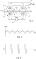
- each DC leakage current detector 58 includes a pair of transformers 64, 66 each formed of a magnetic core 68 and a pair of windings 70, 72, with each of the cores 68 having identical magnetizing characteristics (i.e., B and H field relationships).
- the cores 68 are constructed such that the conductors 18, 20 of the DC bus 22 pass through an opening formed in the core. Because the main power conductors 18, 20 are usually large gauge wires, and in order to simplify the construction of the power circuits, the main power conductors 18, 20 pass through the cores 68 a small number of times, ideally just once.
- the pair of windings 70, 72 wound about each core 68 include an excitation winding 70 and a detection winding 72, with the polarities of the windings being indicated in FIGS. 3 and 6 with the usual convention using dots.
- An excitation/biasing circuit 74 is electrically coupled to the excitation winding 70 of each transformer 64, 66 to selectively inject a current signal thereto, while an output 76 of the detection winding 72 of each transformer 64, 66 - i.e., an output 76 of the detector 58 - is operably connected to the logic circuit 62 to provide output signals.
- the DC leakage current detector 58 detects a leakage current fault by being constructed as and operating its transformers 64, 66 as unsaturated transformers.
- the detector is positioned such that the conductors 18, 20 of the DC power system 12 pass through an opening in each of the cores 68 of the transformers, creating a magnetic field that is the sum of the currents.
- the magnetic field is detected by injecting a small amount of current onto the excitation windings 70 of the transformers 64, 66 via the excitation/biasing circuit 74.
- a typical excitation current injected by excitation/biasing circuit 74 is shown in FIG. 4 as a sawtooth waveform, but it is recognized that other waveform shapes are possible as well.
- the function of the excitation current is to create a changing magnetic flux within the cores 68 that slightly saturates the cores.
- a voltage is monitored on the detection winding 72 on each of the transformers 64, 66 - with the presence or absence of a voltage on the detection windings 72 indicating whether a leakage current is present on the conductors 18, 20 at the monitored location at which the DC leakage current detector 58 is positioned. That is, as long as there is no leakage current through the conductors 18, 20, the flux excursions in each of the cores 68 are equal and opposite. As a result, the voltages generated in each of the detection windings 72 are equal and opposite, and the net voltage at output 76 of the DC leakage current detector 58 is zero.
- the DC leakage current detector 58 detects a leakage current fault by being constructed as and operating its transformers 64, 66 as saturated transformers.
- the polarity of one of the windings 70, 72 in the DC leakage current detector 58 is reversed, as can be seen in FIG. 6 , and both cores 68 are normally saturated.
- the detector is positioned such that the conductors 18, 20 of the DC power system 12 pass through an opening in each of the cores 68 of the transformers 64, 66, creating a magnetic field that is the sum of the currents.
- the magnetic field is detected by injecting a small amount of current into the excitation windings 70 of the transformers 64, 66 via the excitation/biasing circuit 74, with the injected current signals including a DC bias that maintains the transformer cores 68 in saturation.
- a sawtooth waveform excitation current that includes a DC bias is shown in FIG. 7 according to one embodiment.
- a voltage is monitored on the detection winding 72 of each of the transformers 64, 66 - with the presence or absence of a voltage on the detection windings 72 indicating whether a leakage current is present on the conductors 18, 20 at the monitored location at which the DC leakage current detector 58 is positioned.
- the presence of leakage current counteracts the bias in one of the transformers 64, 66, taking it out of saturation, which will cause a voltage to appear on the detection windings 72 on that transformer 64, 66, while under unfaulted conditions there will be no signal.
- a net voltage waveform on the detection winding 72 of the transformer 64, 66 taken out of saturation is then provided to output 76 of the DC leakage current detector 58 and sent to logic device 62, with an example of such a net voltage waveform indicative of a leakage current on the conductors 18, 20 being shown in FIG. 8 .
- the excitation/biasing circuit 74 With respect to the injection current signals generated by excitation/biasing circuit 74 that maintain the transformer cores 68 in saturation, it is recognized that since the amount of leakage current is determined by the sizes of the resistors 55, 56 in the DC power circuit 12 in FIG. 2 that are used to maintain a voltage difference between the vehicle frame 54 and the power circuit, the amount of fault current is known ahead of time, and the excitation/biasing circuit 74 can be designed such that the leakage current approximately counteracts the DC bias in one of the cores 68.
- the embodiments operate on alternating principles with regard to the detection of a leakage current in the conductors 18, 20.
- Another difference between the embodiments of FIGS. 3 and 6 is that the number of turns for each of the excitation windings 70 does not have to be the same for each core 68 for the saturated transformers 64, 66. In fact, depending on the size of the resistors 55, 56 in FIG. 2 , the number of turns for each of the excitation windings 70 would be deliberately different, sized to reflect the difference in the amount of leakage current that flows for a fault from the positive or the negative side of the DC power circuit 12 to the frame 54.
- FIG. 2 While the example therein is shown as including a stand-alone DC leakage current detector 58 on each of the independent branches 60 of the DC distribution bus 22 that collectively operate to identify and locate leakage current faults in the DC power circuit without the use of other/additional fault detection circuitry, it is recognized that other examples may include additional ground fault detection circuitry 48. That is, other known ground fault detection circuitry 48 may be used in combination with DC leakage current detectors 58 to monitor the level of leakage current flowing through the chassis ground 54. Examples of such known ground fault detection circuitry 48 that might be used in combination with DC leakage current detectors 58 is shown in FIGS. 9 and 10 .
- the ground fault detection circuitry 48 may be connected to each terminal 50, 52 of the traction battery 16 and to the DC bus 22 and functions to detect a voltage change in/across a pair of resistors 55, 56 that is indicative of a leakage current in the DC power circuit 12.
- the actual voltage during a fault depends on the ratio of the resistance of the fault leakage path to the resistance of the two biasing resistors 55, 56, with it being recognized that the ratio of the resistance of the usual causes of leakage current to the biasing resistance is low enough to produce a significant change in voltage during a fault. Accordingly, a change in voltage across the either of resistors 55, 56 is easily detected by ground fault detection circuitry 48 to identify the presence of ground fault leakage current to the vehicle frame 54.
- ground fault detection circuitry 48 is provided for identifying leakage current faults in the DC power circuit 12 and DC leakage current detectors 58 are provided on each of the independent branches 60 - including the branch 60 connected to the terminals 50, 52 of the battery charger 16.
- the DC leakage current detectors 58 may be operated as described above with respect to FIGS. 2-8 to detect the leakage current and locate the fault, with the ground fault detection circuitry 48 providing some redundancy in leakage current fault detection when operated along with the DC leakage current detectors 58to increase reliability of leakage current fault detection in the DC power circuit 12.
- the branch 60 connected to the terminals 50, 52 of the battery charger 16 does not include a DC leakage current detector 58 thereon.
- the location of a leakage fault may still be identified either by the other DC leakage current detectors 58 or, if none of the DC leakage current detectors 58 detects a fault but a fault is detected by the ground fault detection circuitry 48, then it is known that the leakage fault is located on the branch without a DC leakage current detector 58 thereon.
- embodiments of the invention thus provide a system and method for leakage current detection and fault location identification in a DC power circuit in hybrid and electric vehicles.
- a plurality of DC leakage current detectors are positioned throughout the DC power circuit, with the DC leakage current detectors functioning to determine the path of any leakage current in the DC power circuit.
- the system includes a DC power circuit having a DC bus comprising a pair of conductors, one or more energy storage devices connected to the DC bus to provide a DC power thereto, one or more power converters connected to the DC bus and configured to condition the DC power, and one or more loads positioned to receive power from the DC bus or the one of the respective one or more power converters.
- the system also includes a plurality of DC leakage current detectors positioned throughout the DC power circuit, the plurality of DC leakage current detector configured to sense and locate a leakage current fault in the DC power circuit, and wherein each of the plurality of DC leakage current detectors is configured to generate a net voltage at an output thereof indicative of whether a leakage current fault is present at a location at which the respective DC leakage current detector is positioned.
- a method of sensing and locating a leakage current fault in a DC power circuit comprising a plurality of independent branches includes positioning a plurality of DC leakage current detectors throughout the DC power circuit on at least a portion of the independent branches.
- the method also includes generating, at each of the plurality of DC leakage current detectors, a net voltage output indicative of whether a leakage current fault is present at a location at which the respective DC leakage current detector is positioned and transmitting an output signal from each of the plurality of DC leakage current detectors to a logic device operably connected to the plurality of DC leakage current detectors, the output signal from each respective DC leakage current detector being representative of the net voltage output thereof.
- the method further includes analyzing, via the logic device, the output signals transmitted from the plurality of DC leakage current detectors to identify a location of a leakage current fault in the DC power circuit.
- a vehicle in accordance with yet another embodiment of the invention, includes the system according to claim 1, and in particular, a chassis and a DC power circuit electrically isolated from the chassis, the DC power circuit including a DC distribution bus comprising a plurality of independent branches and a plurality of system components electrically coupled to the DC distribution bus, the plurality of system components including one or more of each of energy storage devices, power converters, and vehicle loads.
- the vehicle also includes a plurality of DC leakage current detectors positioned throughout the DC power circuit on the plurality of independent branches, the plurality of DC leakage current detector configured to sense a leakage current fault in the DC power circuit.
- the vehicle further includes a logic device in operable communication with the plurality of DC leakage current detectors, the logic device being programmed to receive output signals from each of the plurality of DC leakage current detectors, the output signals comprising net voltage output data from each respective DC leakage current detector indicative of whether a leakage current fault is present at a location at which the respective DC leakage current detector is positioned.
- the logic device is further programmed to locate the leakage current fault in the DC power circuit based on the output signals received from the plurality of DC leakage current detectors.
Landscapes
- Engineering & Computer Science (AREA)
- Mechanical Engineering (AREA)
- Physics & Mathematics (AREA)
- General Physics & Mathematics (AREA)
- Power Engineering (AREA)
- Transportation (AREA)
- Computer Hardware Design (AREA)
- Microelectronics & Electronic Packaging (AREA)
- Chemical & Material Sciences (AREA)
- Combustion & Propulsion (AREA)
- Electric Propulsion And Braking For Vehicles (AREA)
- Emergency Protection Circuit Devices (AREA)
Description
- The invention relates generally to a DC power circuit in hybrid and electric vehicles and, more particularly, to a system and method for leakage current detection and fault location identification in a DC power circuit in hybrid and electric vehicles.
- Hybrid electric vehicles may combine an internal combustion engine and an electric motor powered by an energy storage device, such as a traction battery, to propel the vehicle. Such a combination may increase overall fuel efficiency by enabling the combustion engine and the electric motor to each operate in respective ranges of increased efficiency. Electric motors, for example, may be efficient at accelerating from a standing start, while combustion engines may be efficient during sustained periods of constant engine operation, such as in highway driving. Having an electric motor to boost initial acceleration allows combustion engines in hybrid electric vehicles to be smaller and more fuel efficient.
- Purely electric vehicles use stored electrical energy to power an electric motor, which propels the vehicle and may also operate auxiliary drives. Purely electric vehicles may use one or more sources of stored electrical energy. For example, a first source of stored electrical energy may be used to provide longer-lasting energy while a second source of stored electrical energy may be used to provide higher-power energy for, for example, acceleration.
- Plug-in electric vehicles, whether of the hybrid electric type or of the purely electric type, are configured to use electrical energy from an external source to recharge the traction battery. Such vehicles may include on-road and off-road vehicles, golf cars, neighborhood electric vehicles, forklifts, and utility trucks as examples. These vehicles may use either off-board stationary battery chargers or on-board battery chargers to transfer electrical energy from a utility grid or renewable energy source to the vehicle's on-board traction battery. Plug-in vehicles may include circuitry and connections to facilitate the recharging of the traction battery from the utility grid or other external source, for example. Additionally, an export power inverter may be provided that is able to invert power received from the DC bus of the vehicle and output an AC power that may be provided back to the utility grid or to another AC load that might require power.
- The DC power circuit of the vehicle - i.e., the energy storage device(s), battery charger, export inverter and traction motor or other loads connected to a DC bus/network in the vehicle - are generally operated such that they are electrically isolated from the vehicle frame, such that a fault (short circuit) between one of the DC power conductors and the vehicle frame does not produce large fault currents. While such protection is provided due to the isolation of the DC power circuit from the vehicle frame, it is recognized that it is desirable to detect high impedance, low leakage current faults in the DC power circuit during operation of the vehicle, such that a protection strategy is provided to detect a fault and turn off power in the DC power circuit before a second fault develops. Furthermore, in the case that the fault is a leakage current through a person, it is desired to limit the amount of current needed to detect the fault to low levels.
- An example of ground fault circuitry as known in the art for detecting leakage current to a vehicle frame as presented by TDI Power, Inc. is shown in
FIG. 1 , where a vehicleDC power circuit 2 is illustrated that includes groundfault detection circuitry 4 and associatedresistors 6 that functions to detect leakage current to the vehicle frame that arises from a fault anywhere on the DC power bus 8. The groundfault detection circuitry 4 functions to detect a voltage change across the resistor(s) 6 that is indicative of a leakage current in theDC power circuit 2. The actual voltage during a fault depends on the ratio of the resistance of the fault leakage path to the resistance of the twobiasing resistors 6. For the values of theresistors 6 shown inFIG. 1 , the ratio of the resistance of the usual causes of leakage current to the biasing resistance is low enough to produce a significant change in voltage during a fault. During normal conditions, theresistors 6 establish a voltage of 95 volts across the 1 Megaohm resistor. During a fault from positive supply to ground, the voltage across the 1 Megaohm resistor can rise to as high as 380 volts. During a fault from negative supply to ground, the voltage can drop to as low as 0 volts. In the case of thecircuit 2 inFIG. 1 , the current through a fault from the positive side of the DC bus 8 to the vehicle frame is limited to +0.38 milliamps. For a fault from the negative side of the DC bus 8 to the vehicle frame, the fault current is limited to approximately -0.13 milliamps. - However, while the ground fault detection circuitry of
FIG. 1 can detect leakage current to the vehicle frame that arises from a fault anywhere on the DC power bus, the ground fault detection circuitry does not give any indication concerning the location of the fault. That is, the voltage readings acquired/analyzed by the ground fault detection circuitry provides no information on the location of the fault within the vehicle DC power circuit, as the voltage readings are not dependent on the location of the fault. It is recognized that an indication of the location of the fault would be beneficial, in that such information would be useful for diagnostics and repair of the DC power circuit. - It would therefore be desirable to provide a system and method for leakage current detection and fault location identification in a DC power circuit in hybrid and electric vehicles. Such a system and method would identify the location of a fault in the DC power circuit, so as to provide for diagnostics and repair of the DC power circuit. The system and method could be employed in a stand-alone fashion without use of other known fault detection circuitry, or could also be used in combination with other known fault detection circuitry.
-
US2016/091551 discloses leakage current detection for vehicles. - The invention is defined by the appended claims. According to one aspect of the invention, a system includes a DC power circuit having a DC bus comprising a pair of conductors, one or more energy storage devices connected to the DC bus to provide a DC power thereto, one or more power converters connected to the DC bus and configured to condition the DC power, and one or more loads positioned to receive power from the DC bus or the one of the respective one or more power converters. The system also includes a plurality of DC leakage current detectors positioned throughout the DC power circuit, the plurality of DC leakage current detector configured to sense and locate a leakage current fault in the DC power circuit, and wherein each of the plurality of DC leakage current detectors is configured to generate a net voltage at an output thereof indicative of whether a leakage current fault is present at a location at which the respective DC leakage current detector is positioned.
- In accordance with another aspect of the invention, a method of sensing and locating a leakage current fault in a DC power circuit comprising a plurality of independent branches is disclosed. The method includes positioning a plurality of DC leakage current detectors throughout the DC power circuit on at least a portion of the independent branches. The method also includes generating, at each of the plurality of DC leakage current detectors, a net voltage output indicative of whether a leakage current fault is present at a location at which the respective DC leakage current detector is positioned and transmitting an output signal from each of the plurality of DC leakage current detectors to a logic device operably connected to the plurality of DC leakage current detectors, the output signal from each respective DC leakage current detector being representative of the net voltage output thereof. The method further includes analyzing, via the logic device, the output signals transmitted from the plurality of DC leakage current detectors to identify a location of a leakage current fault in the DC power circuit.
- In accordance with yet another aspect of the invention, a vehicle includes a chassis and a DC power circuit electrically isolated from the chassis, the DC power circuit including a DC distribution bus comprising a plurality of independent branches and a plurality of system components electrically coupled to the DC distribution bus, the plurality of system components including one or more of each of energy storage devices, power converters, and vehicle loads. The vehicle also includes a plurality of DC leakage current detectors positioned throughout the DC power circuit on the plurality of independent branches, the plurality of DC leakage current detector configured to sense a leakage current fault in the DC power circuit. The vehicle further includes a logic device in operable communication with the plurality of DC leakage current detectors, the logic device being programmed to receive output signals from each of the plurality of DC leakage current detectors, the output signals comprising net voltage output data from each respective DC leakage current detector indicative of whether a leakage current fault is present at a location at which the respective DC leakage current detector is positioned. The logic device is further programmed to locate the leakage current fault in the DC power circuit based on the output signals received from the plurality of DC leakage current detectors.
- Various other features and advantages will be made apparent from the following detailed description and the drawings.
- The drawings illustrate embodiments presently contemplated for carrying out the invention.
- In the drawings:
-
FIG. 1 is a schematic diagram of a DC power circuit in an electric vehicle and associated ground fault detection circuitry, as known in the prior art. -
FIG. 2 is a schematic diagram of a DC power circuit in an electric vehicle with a plurality of DC leakage current detectors positioned throughout the circuit, according to an embodiment of the invention. -
FIG. 3 is a schematic diagram of a DC leakage current detector with unsaturated transformers, according to an embodiment of the invention. -
FIG. 4 is a graph illustrating a sawtooth excitation current waveform injected into an excitation windings of the DC leakage current detector ofFIG. 3 , according to an embodiment of the invention. -
FIG. 5 is a graph illustrating a net voltage output waveform produced by the DC leakage current detector ofFIG. 3 responsive to a leakage current in the DC power circuit along the measured branch thereof, according to an embodiment of the invention. -
FIG. 6 is a schematic diagram of a DC leakage current detector with saturated transformers, according to an embodiment of the invention. -
FIG. 7 is a graph illustrating a sawtooth excitation current waveform injected into an excitation windings of the DC leakage current detector ofFIG. 6 , according to an embodiment of the invention. -
FIG. 8 is a graph illustrating a net voltage output waveform produced by the DC leakage current detector ofFIG. 6 responsive to a leakage current in the DC power circuit along the measured branch thereof, according to an embodiment of the invention. -
FIGS. 9 and10 are schematic diagrams of DC power circuits in an electric vehicle with a plurality of DC leakage current detectors positioned throughout the circuit, along with additional ground fault detection circuitry, according to embodiments of the invention. - Embodiments of the invention are directed to a system and method for leakage current detection and fault location identification in a DC power circuit in hybrid and electric vehicles. Ground fault detection circuitry is provided for the DC power circuit that includes a plurality of DC leakage current detectors positioned throughout the DC power circuit, with the DC leakage current detectors functioning to determine the path of any leakage current in the DC power circuit.
- While embodiments of the invention are described below as part of a plug-in electric vehicle implantation/embodiment, it is recognized that embodiments of the invention may also be incorporated into hybrid plug-in electric vehicles, non-plug-in electric vehicles, and other general DC power circuits with numerous branches (other than in a vehicle environment) where it is desirable to be able to identify the location of a current fault in the circuit. Thus, it is recognized that embodiments of the invention are not meant to be limited to plug-in electric vehicles or electric/hybrid vehicles in general, and that embodiments of the invention may be utilized with/in other general DC power circuits with numerous branches.
- Referring to
FIG. 2 , a plug-inelectric vehicle 10 is depicted with which and in which embodiments of the invention may be employed. The plug-inelectric vehicle 10 includes aDC power circuit 12 that distributes power amongst one or more energy storage devices, loads, and power converters included in the circuit. A typical plug-inelectric vehicle 10 includes, as part ofDC power circuit 12, an electrical device ormachine 14 capable of operating as a motor or a generator. In one embodiment,electrical machine 14 is a traction motor mechanically coupled to one or more driving wheels or axles (not shown) of thevehicle 10 to provide propulsion to the vehicle, when operating as a motor. During a regenerative braking of thevehicle 10, theelectrical machine 14 acts as a generator by recovering energy that would normally be lost in the friction braking system. - As shown in
FIG. 2 , theDC power circuit 12 also includes a traction battery orbattery pack 16 that stores energy that can be used by theelectrical machine 14. In one embodiment,vehicle battery pack 16 provides a high voltage DC output onto a pair ofconductors DC distribution bus 22 coupled thereto. One ormore power converters DC distribution bus 22. Thepower converters distribution bus 22 into a form useable by theelectrical machine 14 and/or other loads 28 - with one or more of thepower converters traction battery 16 and theelectrical machine 14, for example. According to embodiments, thepower converters AC voltage inverter 24 coupled toDC distribution bus 22 to invert a DC power on the DC bus to a three-phase AC power used by theelectrical machine 14. In a regenerative mode where theelectrical machine 14 acts as a generator, the DC-to-AC voltage inverter 24 may convert the three-phase AC current generated by theelectrical machine 14 to the DC voltage compatible with thetraction battery 16. The bi-directional DC-to-AC voltage inverter 24 may be of a known construction and include six half phase modules (not shown) that are paired to form three phases. Thepower converters DC voltage converters 26 configured to convert one DC voltage into another DC voltage. Such DC-to-DC voltage converters 26 may be of a known construction and include an inductor coupled to a pair of switches and coupled to a pair of diodes (not shown), with the switches being controlled to buck or boost a voltage from theDC distribution bus 22 to a level suitable for use by anothervehicle load 28 that receives power therefrom - such as a heating module or an air-conditioning module, for example. - When plug-in
electric vehicle 10 is parked or not in use, it may be desirable to plug the vehicle into, for example, the utility grid or to a renewable energy source to refresh or recharge thebattery pack 16. Accordingly,FIG. 2 shows theDC power circuit 12 of thevehicle 10 including acharging system 30 for the recharging ofvehicle battery pack 16. Chargingsystem 30 includes acharge port 32 that may be any type of port configured to receive a charge connector (e.g. power cord/plug) therein to transfer power from the external power source to thevehicle 10. Thecharge port 32 may be electrically connected to a charger or on-board power conversion module 34 (i.e., "battery charger") that conditions power supplied from thecharge port 32 to provide the proper voltage and current levels to thetraction battery 16, such as via rectification and/or DC-DC conversion of power received from the external power source. Power conditioned by thebattery charger 34 is then provided to theDC distribution bus 22. - In one embodiment, an
export power inverter 36 is also included inDC power circuit 12. Theexport inverter 36 may be provided that is able to invert power received from theDC distribution bus 22 of the vehicle and output an AC power that may be provided back to the utility grid or to another AC load that might require power. As shown inFIG. 2 , a plurality ofswitches export inverter 36 to either the utility grid or to an external AC load. A first pair ofcontactors 38 is provided to selectively connect the output of theexport inverter 36 to the utility grid and a second pair ofcontactors 40 is provided to selectively connect the output of theexport inverter 36 to the external AC load. Each of the first and second pairs ofcontactors export inverter 36 to one of the utility grid or the external AC load. - For operating and controlling the various components of the
DC power circuit 12 described above, one or more associatedcontrollers 44 is included in the plug-inelectric vehicle 10 to control and monitor the operation of the components. The controller(s) 44 may communicate via a serial bus (e.g., Controller Area Network (CAN)) or via discrete conductors, and asystem controller 46 may be present to coordinate the operation of thevarious controllers 44 and their associated components. - As shown in
FIG. 2 , thetraction battery 16 may have apositive terminal 50 and anegative terminal 52 connected toconductors DC bus 22. Electrical isolation between thetraction battery terminals battery terminals chassis ground 54. Thechassis ground 54 is defined as a common reference point to which electrical devices of theDC power circuit 12 are electrically connected to. The electrical isolation may be described as a leakage resistance between thechassis ground 54 and a terminal 50, 52 of thetraction battery 16. Under normal conditions, a leakage resistance (that may occur at various locations within the DC power circuit 12) will have a relatively large value and little or no leakage current will flow through thechassis ground 54. However, under fault conditions, the leakage resistance can decrease such that larger levels of leakage current flow through thechassis ground 54. - According to embodiments of the invention, a plurality of DC leakage
current detectors 58 are placed throughout theDC power circuit 12 ofvehicle 10 for detecting the presence of electrical isolation issues. The DC leakagecurrent detectors 58 function to detect leakage current to thevehicle frame 54 that arises from a fault anywhere in theDC power circuit 12, and further function to locate the low leakage current fault - with operation of the DC leakagecurrent detectors 58 enabling a determination of the path of the leakage current within theDC power circuit 12. More specifically, a DC leakagecurrent detector 58 is positioned on each of a number ofindependent branches 60 of theDC bus 22 ofDC power circuit 12, with eachbranch 60 including thereon a component of the DC power circuit 12 (e.g.,battery pack 16,electrical machine 14, DC-AC inverter 24, DC-DC converter 26,battery charger 34,export inverter 36, etc.). In such a manner, each of theindependent branches 60 of theDC bus 22 can be separately monitored to detect a leakage current therein. - An exemplary placement of the DC leakage
current detectors 58 in/on theDC power circuit 12 is shown inFIG. 2 , with each of thedetectors 58 being indicated as being positioned around pairs ofconductors respective branch 60 of theDC bus 22. The path of the leakage current is then determined by observing which DC leakagecurrent detectors 58 detect the leakage current and which DC leakagecurrent detectors 58 do not. The DC leakagecurrent detectors 58 are connected to alogic device 62 that, according to embodiments of the invention, may be incorporated intosystem controller 46 or may be provided as a separate controller or logic device, with outputs of the DC leakagecurrent detectors 58 being provided to thelogic device 62 to determine the fault location. That is, thelogic device 62 functions to determine the fault location based on which particular DC leakagecurrent detectors 58 indicate a fault. As one example, a fault at theterminals battery charger 16 will cause leakage current to flow from thebattery pack 16 to thebattery charger 34, such that the DC leakagecurrent detector 58 at the terminals of thebattery pack 16 and the DC leakagecurrent detector 58 at thebattery charger 34 will detect the fault, while DC leakagecurrent detectors 58 at the terminals of theexport inverter 36 and at thepropulsion motor 14 will not detect the fault - therefore causing thelogic device 62 to determine that the fault is located on a path between thebattery pack 16 and thebattery charger 34. - In general, any sort of sensor within the limitations set forth by the claims, that can detect DC leakage current can be used as the DC leakage
current detectors 58. According to the invention, the DC leakagecurrent detector 58 is comprised of a pair of transformers, as will be described in greater detail hereafter with respect toFIGS. 3-8 , which are directed to a construction of the transformers and operation thereof in detecting DC leakage current. As shown inFIGS. 3 and6 , each DC leakagecurrent detector 58 includes a pair oftransformers magnetic core 68 and a pair ofwindings cores 68 having identical magnetizing characteristics (i.e., B and H field relationships). Thecores 68 are constructed such that theconductors DC bus 22 pass through an opening formed in the core. Because themain power conductors main power conductors windings FIGS. 3 and6 with the usual convention using dots. An excitation/biasingcircuit 74 is electrically coupled to the excitation winding 70 of eachtransformer output 76 of the detection winding 72 of eachtransformer 64, 66 - i.e., anoutput 76 of the detector 58 - is operably connected to thelogic circuit 62 to provide output signals. - According to the invention, and as shown in
FIG. 3 , the DC leakagecurrent detector 58 detects a leakage current fault by being constructed as and operating itstransformers current detector 58, the detector is positioned such that theconductors DC power system 12 pass through an opening in each of thecores 68 of the transformers, creating a magnetic field that is the sum of the currents. The magnetic field is detected by injecting a small amount of current onto theexcitation windings 70 of thetransformers circuit 74. A typical excitation current injected by excitation/biasingcircuit 74 is shown inFIG. 4 as a sawtooth waveform, but it is recognized that other waveform shapes are possible as well. The function of the excitation current is to create a changing magnetic flux within thecores 68 that slightly saturates the cores. - Upon injection of a current signal into the excitation winding 70 on each of the
transformers transformers 64, 66 - with the presence or absence of a voltage on thedetection windings 72 indicating whether a leakage current is present on theconductors current detector 58 is positioned. That is, as long as there is no leakage current through theconductors cores 68 are equal and opposite. As a result, the voltages generated in each of thedetection windings 72 are equal and opposite, and the net voltage atoutput 76 of the DC leakagecurrent detector 58 is zero. However, the presence of leakage current on theconductors cores 68 to be broken. As a result, there will be brief periods when onecore 68 is saturated and the other is not, which will produce a net voltage waveform on thedetection windings 72 that is then output from the DC leakagecurrent detector 58 atoutput 76. An example of such a net voltage waveform atoutput 76 that is indicative of a leakage current on theconductors FIG. 5 . - According to the invention, and as shown in
FIG. 6 , the DC leakagecurrent detector 58 detects a leakage current fault by being constructed as and operating itstransformers FIG. 3 , the polarity of one of thewindings current detector 58 is reversed, as can be seen inFIG. 6 , and bothcores 68 are normally saturated. In operation of the DC leakagecurrent detector 58, the detector is positioned such that theconductors DC power system 12 pass through an opening in each of thecores 68 of thetransformers excitation windings 70 of thetransformers circuit 74, with the injected current signals including a DC bias that maintains thetransformer cores 68 in saturation. A sawtooth waveform excitation current that includes a DC bias is shown inFIG. 7 according to one embodiment. - Upon injection of a current signal into the excitation winding 70 on each of the
transformers transformers 64, 66 - with the presence or absence of a voltage on thedetection windings 72 indicating whether a leakage current is present on theconductors current detector 58 is positioned. In the unsaturated transformer embodiment ofFIG. 6 , the presence of leakage current counteracts the bias in one of thetransformers detection windings 72 on thattransformer transformer output 76 of the DC leakagecurrent detector 58 and sent tologic device 62, with an example of such a net voltage waveform indicative of a leakage current on theconductors FIG. 8 . - With respect to the injection current signals generated by excitation/biasing
circuit 74 that maintain thetransformer cores 68 in saturation, it is recognized that since the amount of leakage current is determined by the sizes of theresistors DC power circuit 12 inFIG. 2 that are used to maintain a voltage difference between thevehicle frame 54 and the power circuit, the amount of fault current is known ahead of time, and the excitation/biasingcircuit 74 can be designed such that the leakage current approximately counteracts the DC bias in one of thecores 68. - Thus, with regard to the saturated and unsaturated transformer constructions/operations shown and described in
FIGS. 3-8 , it can thus be seen that the embodiments operate on alternating principles with regard to the detection of a leakage current in theconductors FIGS. 3 and6 is that the number of turns for each of theexcitation windings 70 does not have to be the same for each core 68 for the saturatedtransformers resistors FIG. 2 , the number of turns for each of theexcitation windings 70 would be deliberately different, sized to reflect the difference in the amount of leakage current that flows for a fault from the positive or the negative side of theDC power circuit 12 to theframe 54. - Referring back now to
FIG. 2 , while the example therein is shown as including a stand-alone DC leakagecurrent detector 58 on each of theindependent branches 60 of theDC distribution bus 22 that collectively operate to identify and locate leakage current faults in the DC power circuit without the use of other/additional fault detection circuitry, it is recognized that other examples may include additional groundfault detection circuitry 48. That is, other known groundfault detection circuitry 48 may be used in combination with DC leakagecurrent detectors 58 to monitor the level of leakage current flowing through thechassis ground 54. Examples of such known groundfault detection circuitry 48 that might be used in combination with DC leakagecurrent detectors 58 is shown inFIGS. 9 and10 . As shown therein, the groundfault detection circuitry 48 may be connected to each terminal 50, 52 of thetraction battery 16 and to theDC bus 22 and functions to detect a voltage change in/across a pair ofresistors DC power circuit 12. The actual voltage during a fault depends on the ratio of the resistance of the fault leakage path to the resistance of the two biasingresistors resistors fault detection circuitry 48 to identify the presence of ground fault leakage current to thevehicle frame 54. - In the embodiment of
FIG. 9 , groundfault detection circuitry 48 is provided for identifying leakage current faults in theDC power circuit 12 and DC leakagecurrent detectors 58 are provided on each of the independent branches 60 - including thebranch 60 connected to theterminals battery charger 16. The DC leakagecurrent detectors 58 may be operated as described above with respect toFIGS. 2-8 to detect the leakage current and locate the fault, with the groundfault detection circuitry 48 providing some redundancy in leakage current fault detection when operated along with the DC leakage current detectors 58to increase reliability of leakage current fault detection in theDC power circuit 12. In the alternative example shown inFIG. 10 , thebranch 60 connected to theterminals battery charger 16 does not include a DC leakagecurrent detector 58 thereon. In such an example, the location of a leakage fault may still be identified either by the other DC leakagecurrent detectors 58 or, if none of the DC leakagecurrent detectors 58 detects a fault but a fault is detected by the groundfault detection circuitry 48, then it is known that the leakage fault is located on the branch without a DC leakagecurrent detector 58 thereon. - Beneficially, embodiments of the invention thus provide a system and method for leakage current detection and fault location identification in a DC power circuit in hybrid and electric vehicles. A plurality of DC leakage current detectors are positioned throughout the DC power circuit, with the DC leakage current detectors functioning to determine the path of any leakage current in the DC power circuit.
- According to the invention, the system includes a DC power circuit having a DC bus comprising a pair of conductors, one or more energy storage devices connected to the DC bus to provide a DC power thereto, one or more power converters connected to the DC bus and configured to condition the DC power, and one or more loads positioned to receive power from the DC bus or the one of the respective one or more power converters. The system also includes a plurality of DC leakage current detectors positioned throughout the DC power circuit, the plurality of DC leakage current detector configured to sense and locate a leakage current fault in the DC power circuit, and wherein each of the plurality of DC leakage current detectors is configured to generate a net voltage at an output thereof indicative of whether a leakage current fault is present at a location at which the respective DC leakage current detector is positioned.
- In accordance with another embodiment of the invention, a method of sensing and locating a leakage current fault in a DC power circuit comprising a plurality of independent branches is disclosed. According to the invention, the method includes positioning a plurality of DC leakage current detectors throughout the DC power circuit on at least a portion of the independent branches. The method also includes generating, at each of the plurality of DC leakage current detectors, a net voltage output indicative of whether a leakage current fault is present at a location at which the respective DC leakage current detector is positioned and transmitting an output signal from each of the plurality of DC leakage current detectors to a logic device operably connected to the plurality of DC leakage current detectors, the output signal from each respective DC leakage current detector being representative of the net voltage output thereof. The method further includes analyzing, via the logic device, the output signals transmitted from the plurality of DC leakage current detectors to identify a location of a leakage current fault in the DC power circuit.
- In accordance with yet another embodiment of the invention, a vehicle includes the system according to claim 1, and in particular, a chassis and a DC power circuit electrically isolated from the chassis, the DC power circuit including a DC distribution bus comprising a plurality of independent branches and a plurality of system components electrically coupled to the DC distribution bus, the plurality of system components including one or more of each of energy storage devices, power converters, and vehicle loads. The vehicle also includes a plurality of DC leakage current detectors positioned throughout the DC power circuit on the plurality of independent branches, the plurality of DC leakage current detector configured to sense a leakage current fault in the DC power circuit. The vehicle further includes a logic device in operable communication with the plurality of DC leakage current detectors, the logic device being programmed to receive output signals from each of the plurality of DC leakage current detectors, the output signals comprising net voltage output data from each respective DC leakage current detector indicative of whether a leakage current fault is present at a location at which the respective DC leakage current detector is positioned. The logic device is further programmed to locate the leakage current fault in the DC power circuit based on the output signals received from the plurality of DC leakage current detectors.
- While the invention has been described in detail in connection with only a limited number of embodiments, it should be readily understood that the invention is not limited to such disclosed embodiments. Rather, the invention can be modified to incorporate any number of variations, alterations, substitutions or equivalent arrangements not heretofore described, but which are within the scope of the appended claims. Additionally, while various embodiments of the invention have been described, it is to be understood that aspects of the invention may include only some of the described embodiments. Accordingly, the invention is not to be seen as limited by the foregoing description, but is only limited by the scope of the appended claims.
Claims (12)
- A system comprising:a DC power circuit (12) including:a DC bus (22) comprising a pair of conductors (18,20);one or more energy storage devices (16) connected to the DC bus to provide a DC power thereto;one or more power converters (24, 26) connected to the DC bus (22) and configured to condition the DC power; andone or more loads positioned to receive power from the DC bus (22) or the one of the respective one or more power converters; anda plurality of DC leakage current detectors (58) positioned throughout the DC power circuit (12), the plurality of DC leakage current detectors (58) being configured to sense and locate a leakage current fault in the DC power circuit (12);wherein:each of the plurality of DC leakage current detectors (58) is configured to generate a net voltage at an output thereof indicative of whether a leakage current fault is present at a location at which the respective DC leakage current detector is positioned;each of the plurality of DC leakage current detectors (58) comprises:a pair of transformers (64, 66), each of the pair of transformers (64, 66) including:a magnetic core (68) positioned about the pair of conductors (18, 20) of the DC bus (22); anda pair of windings (70, 72) wound about the magnetic core (68), the pair of windings (70, 72) including an excitation winding (70) and a detection winding (72);a biasing circuit (74) connected to the excitation winding (70) in each of the pair of transformers (64, 66) to inject a current signal thereto; anda detector output (76) connected to the detection winding (72) in each of the pair of transformers (64, 66) to receive a voltage therefrom, such that the net voltage is present at the detector output (76);the pair of transformers (64, 66) is configured to be operated as saturated transformers, with the injected current signal including a DC bias that maintains the magnetic cores of the transformers in saturation;the number of turns of each of the excitation windings (70) for each magnetic core (68) of the DC leakage detectors is different; andthe system is configured such that when leakage current is present in the conductors (18, 20) at the location of the respective DC leakage current detector, the magnetic core of one transformer is taken out of saturation and the magnetic core of the other transformer remains in saturation, such that the net voltage at the detector output (76) has a non-zero value.
- The system of claim 1, further comprising a logic device (62) operably coupled to the plurality of DC leakage current detectors (58), the logic device (62) configured to:receive an output signal from each of the plurality of DC leakage current detectors (58), the output signal being representative of the net voltage at the output of the respective DC leakage current detector; andlocate the leakage current fault in the DC power circuit (12) based on the output signals received from the plurality of DC leakage current detectors;wherein a pattern of the output signals, and their being indicative of the leakage current fault being present at the location at which the respective DC leakage current detector is positioned, being analyzed to locate the leakage current fault in the DC power circuit (12).
- The system of claim 1, wherein the DC bus (22) comprises a plurality of independent branches (60), with each independent branch including thereon a respective one of the energy storage devices, power converters, or loads thereon.
- The system claim 3, wherein a respective DC leakage current detector of the plurality of DC leakage current detectors (58) is positioned on each of the plurality of independent branches (60).
- The system of claim 3, further comprising ground fault detection circuitry (48) and associated resistors (55, 56) configured to detect leakage current on an independent branch of the DC bus.
- The system of claim 5, wherein the ground fault detection circuitry (48) and associated resistors (55, 56) are positioned on one independent branch of the DC bus (22) and the plurality of DC leakage current detectors (58) are positioned on remaining independent branches of the DC bus.
- The system of claim 5, wherein the ground fault detection circuitry (48) and associated resistors (55, 56) are positioned on one independent branch of the DC bus and a respective DC leakage current detector of the plurality of DC leakage current detectors (58) is positioned on each of the plurality of independent branches, including the independent branch with the ground fault detection circuitry (48) and associated resistors (55, 56).
- A method of sensing and locating a leakage current fault in a system according to any of claims 1 to 7, the method comprising:generating, at each of the plurality of DC leakage current detectors (58), a net voltage output indicative of whether a leakage current fault is present at a location at which the respective DC leakage current detector is positioned;transmitting an output signal from each of the plurality of DC leakage current detectors (58) to a logic device (62) operably connected to the plurality of DC leakage current detectors (58), the output signal from each respective DC leakage current detector being representative of the net voltage output thereof; andanalyzing, via the logic device (62), the output signals transmitted from the plurality of DC leakage current detectors (58) to identify a location of a leakage current fault in the DC power circuit (12).
- The method of claim 8 in a system according to claim 3, further comprising positioning ground fault detection circuitry (48) and associated resistors (55, 56) on one independent branch of the DC bus (22),
wherein positioning the plurality of DC leakage current detectors (58) comprises one of:positioning a DC leakage current detector on each of the plurality of independent branches (60) except for the one independent branch on which the ground fault detection circuitry (48) and the associated resistors (55, 56) are positioned; orpositioning a DC leakage current detector on each of the plurality of independent branches, such that the ground fault detection circuitry and associated resistors and a DC leakage current detector are redundantly positioned on the one independent branch. - A vehicle (10) comprising a system according to claim 1, the vehicle comprising:a chassis, wherein the DC power circuit (12) is electrically isolated from the chassis; anda logic device (62) in operable communication with the plurality of DC leakage current detectors (58), the logic device (62) being programmed to:receive output signals (76) from each of the plurality of DC leakage current detectors (58), the output signals being representative of the net voltage output from each respective DC leakage current detector; andlocate the leakage current fault in the DC power circuit (12) based on the output signals received from the plurality of DC leakage current detectors (58).
- The vehicle (10) of claim 10, wherein, in locating the leakage current fault in the DC power circuit (12), the logic device (62) is programmed to assess a pattern of the output signals (76), and their being indicative of the leakage current fault being present at the location at which the respective DC leakage current detector is positioned, to determine a path of the leakage current fault in the DC power circuit (12).
- The vehicle of claim 10, further comprising ground fault detection circuitry (48) and associated resistors (55, 56) configured to detect leakage current on one independent branch of the DC bus, the ground fault detection circuitry (48) being used in combination with a respective DC leakage current detector on the one independent branch.
Applications Claiming Priority (2)
| Application Number | Priority Date | Filing Date | Title |
|---|---|---|---|
| US15/379,126 US10168372B2 (en) | 2016-12-14 | 2016-12-14 | System and method for leakage current and fault location detection in electric vehicle DC power circuits |
| PCT/US2017/062613 WO2018111507A1 (en) | 2016-12-14 | 2017-11-20 | System and method for leakage current and fault location detection in electric vehicle dc power circuites |
Publications (3)
| Publication Number | Publication Date |
|---|---|
| EP3554885A1 EP3554885A1 (en) | 2019-10-23 |
| EP3554885A4 EP3554885A4 (en) | 2020-08-26 |
| EP3554885B1 true EP3554885B1 (en) | 2023-06-28 |
Family
ID=62488321
Family Applications (1)
| Application Number | Title | Priority Date | Filing Date |
|---|---|---|---|
| EP17880066.0A Active EP3554885B1 (en) | 2016-12-14 | 2017-11-20 | System and method for leakage current and fault location detection in electric vehicle dc power circuites |
Country Status (4)
| Country | Link |
|---|---|
| US (1) | US10168372B2 (en) |
| EP (1) | EP3554885B1 (en) |
| CN (1) | CN110072728B (en) |
| WO (1) | WO2018111507A1 (en) |
Families Citing this family (12)
| Publication number | Priority date | Publication date | Assignee | Title |
|---|---|---|---|---|
| EP3608152B1 (en) * | 2018-08-06 | 2022-06-22 | Ningbo Geely Automobile Research & Development Co. Ltd. | Method for detecting an isolation fault |
| CN111983505A (en) * | 2019-05-06 | 2020-11-24 | 江苏新安电器股份有限公司 | Washing machine electric leakage detection system |
| MX2022002704A (en) * | 2019-09-05 | 2022-06-14 | Aclara Tech Llc | System and method for sensing one or more power lines. |
| DE102019217083A1 (en) * | 2019-11-06 | 2021-05-06 | Robert Bosch Gmbh | Monitoring arrangement for the detection of supply line faults for a control unit |
| US11313917B2 (en) * | 2020-05-13 | 2022-04-26 | Lear Corporation | Electric current sensor for detecting leakage current |
| JP7512947B2 (en) * | 2021-05-11 | 2024-07-09 | トヨタ自動車株式会社 | Charging control device and vehicle |
| CN113985118B (en) * | 2021-10-29 | 2024-11-22 | 东风汽车有限公司东风日产乘用车公司 | On-board current fault detection device |
| US11440427B1 (en) * | 2021-11-01 | 2022-09-13 | Beta Air, Llc | Systems and methods for pre-charging short circuit detection in electric aircraft |
| US12491784B2 (en) * | 2021-11-01 | 2025-12-09 | Beta Air Llc | Systems and methods for pre-charging short circuit detection in electric aircraft |
| CN114089119A (en) * | 2021-11-24 | 2022-02-25 | 奇瑞商用车(安徽)有限公司 | High-voltage circuit fault location method, device, electric vehicle and storage medium |
| CN114184981B (en) * | 2021-12-10 | 2023-12-22 | 国网福建省电力有限公司南平供电公司 | Low-voltage leakage positioning equipment and offline leakage assessment method |
| CN116643204B (en) * | 2023-04-14 | 2026-03-24 | 长沙市轨道交通集团有限公司 | Methods for locating leakage faults and protecting against leakage current in maglev transportation traction power supply systems |
Family Cites Families (30)
| Publication number | Priority date | Publication date | Assignee | Title |
|---|---|---|---|---|
| US5508872A (en) | 1994-01-24 | 1996-04-16 | Ford Motor Company | Circuit for ground fault detection and switching |
| WO1998016839A1 (en) | 1996-10-14 | 1998-04-23 | Siemens Aktiengesellschaft | Method and device for measuring current |
| JPH1164391A (en) * | 1997-08-19 | 1999-03-05 | Tempearl Ind Co Ltd | Noncontact ac microcurrent detection circuit |
| JP3658503B2 (en) | 1998-07-03 | 2005-06-08 | 株式会社日立製作所 | Vehicle power supply device and aggregate wiring device |
| US6388451B1 (en) | 2000-08-16 | 2002-05-14 | Ford Global Technologies, Inc. | Leakage current cancellation device |
| JP2003315374A (en) | 2002-04-18 | 2003-11-06 | Mitsubishi Electric Corp | DC leakage detector |
| US7358442B2 (en) * | 2003-09-30 | 2008-04-15 | Rockwell Automation Technologies, Inc. | Bus structure for power switching circuits |
| US7064526B2 (en) | 2004-04-23 | 2006-06-20 | Astronics Advanced Electronic Systems Corp. | Fault tolerant architecture for permanent magnet starter generator subsystem |
| US7583483B2 (en) | 2007-10-04 | 2009-09-01 | Lear Corporation | Vehicle AC ground fault detection system |
| JP5674662B2 (en) | 2008-09-01 | 2015-02-25 | エルジー・ケム・リミテッド | Battery leakage current sensing device and method, and battery driving device and battery pack including the device |
| US8040139B2 (en) | 2009-02-16 | 2011-10-18 | Maxim Integrated Products, Inc. | Fault detection method for detecting leakage paths between power sources and chassis |
| DE102010007452A1 (en) | 2010-02-10 | 2011-08-11 | Siemens Aktiengesellschaft, 80333 | Switching relief for a circuit breaker |
| US8289664B2 (en) | 2010-03-08 | 2012-10-16 | Pass & Seymour, Inc. | Protective device for an electrical supply facility |
| US9290097B2 (en) * | 2010-11-05 | 2016-03-22 | Robert Louis Steigerwald | Apparatus for transferring energy using onboard power electronics with high-frequency transformer isolation and method of manufacturing same |
| US8472154B2 (en) | 2010-12-08 | 2013-06-25 | General Electric Company | Systems, methods, and apparatus for leakage current masking and ground fault detection |
| JP2012153197A (en) | 2011-01-24 | 2012-08-16 | Stanley Electric Co Ltd | Ground fault countermeasure device of onboard electrical equipment system |
| CN103444041A (en) | 2011-03-23 | 2013-12-11 | 丰田自动车株式会社 | Adapter, and vehicle which supplies power using same |
| US8168315B1 (en) | 2011-08-23 | 2012-05-01 | Tesla Motors, Inc. | Method for detecting battery thermal events via battery pack isolation monitoring |
| JP5255112B2 (en) | 2011-12-26 | 2013-08-07 | 本田技研工業株式会社 | Electric vehicle with ground fault detection system |
| JP5674688B2 (en) | 2012-01-25 | 2015-02-25 | 株式会社豊田自動織機 | Earth leakage detector |
| EP2632010B1 (en) | 2012-02-27 | 2015-02-25 | Atreus Enterprises Limited | Leakage current detector for AC and DC systems |
| KR101371854B1 (en) | 2012-08-01 | 2014-03-24 | 기아자동차주식회사 | Electric leakage diagnosis apparatus for vehicle using insulation resistance sensor, and control method thereof |
| US9274158B2 (en) | 2012-11-15 | 2016-03-01 | Ford Global Technologies, Llc | Hybrid/electrical vehicle HV AC system leakage and ground fault detection |
| US9331473B2 (en) | 2012-11-16 | 2016-05-03 | Shakira Limited | Fault detecting device for an electricity supply |
| US9124085B2 (en) * | 2013-11-04 | 2015-09-01 | Gogoro Inc. | Apparatus, method and article for power storage device failure safety |
| US9308826B2 (en) * | 2013-12-19 | 2016-04-12 | Continental Automotive Systems, Inc. | Method and apparatus to detect leakage current between power sources |
| DE102014200681A1 (en) | 2014-01-16 | 2015-07-16 | Robert Bosch Gmbh | Switching device for switching high electrical currents and battery system with such a switching device |
| US10114058B2 (en) * | 2014-09-30 | 2018-10-30 | Ford Global Technologies, Llc | System and method for high voltage leakage detection |
| CN205185893U (en) | 2015-11-23 | 2016-04-27 | 特变电工南京智能电气有限公司 | Multi -functional electric automobile alternating -current charging stake |
| US10203363B2 (en) * | 2016-12-14 | 2019-02-12 | General Electric Company | DC leakage current detector and method of operation thereof for leakage current detection in DC power circuits |
-
2016
- 2016-12-14 US US15/379,126 patent/US10168372B2/en active Active
-
2017
- 2017-11-20 EP EP17880066.0A patent/EP3554885B1/en active Active
- 2017-11-20 WO PCT/US2017/062613 patent/WO2018111507A1/en not_active Ceased
- 2017-11-20 CN CN201780076924.1A patent/CN110072728B/en active Active
Also Published As
| Publication number | Publication date |
|---|---|
| US10168372B2 (en) | 2019-01-01 |
| CN110072728B (en) | 2020-07-07 |
| EP3554885A4 (en) | 2020-08-26 |
| EP3554885A1 (en) | 2019-10-23 |
| WO2018111507A1 (en) | 2018-06-21 |
| US20180164361A1 (en) | 2018-06-14 |
| CN110072728A (en) | 2019-07-30 |
Similar Documents
| Publication | Publication Date | Title |
|---|---|---|
| EP3555640B1 (en) | Dc leakage current detector and method of operation thereof for leakage current detector in dc power circuits | |
| EP3554885B1 (en) | System and method for leakage current and fault location detection in electric vehicle dc power circuites | |
| US11745592B2 (en) | Method for detecting an isolation fault | |
| US10114058B2 (en) | System and method for high voltage leakage detection | |
| US10513185B2 (en) | Electrified vehicle ground fault monitoring system | |
| US10476262B2 (en) | Dual-bus battery precharge circuit | |
| US8710800B2 (en) | Vehicle battery with cell balancing current paths and method of charging the same | |
| US20140191720A1 (en) | Charging system and charging control method of electric powered vehicle | |
| CN107804171B (en) | Vehicle high voltage interlock | |
| JP5860886B2 (en) | Battery control device, power storage device, and vehicle | |
| WO2010032320A1 (en) | Abnormality detector of vehicle and vehicle | |
| CN109866646A (en) | Method for the charging station to electric vehicle charging and the preliminary filling electrical testing for licensing electric vehicle charging station | |
| KR20210016234A (en) | Device for detecting current leakage and current leakage detection system including the same | |
| KR20260005837A (en) | Electric vehicle charging controller | |
| JP6356783B2 (en) | Method and structure for detecting errors during charging of an energy storage system | |
| KR102722544B1 (en) | Appratus for determining fuse failure | |
| KR20250011528A (en) | vehicle charging device |
Legal Events
| Date | Code | Title | Description |
|---|---|---|---|
| STAA | Information on the status of an ep patent application or granted ep patent |
Free format text: STATUS: THE INTERNATIONAL PUBLICATION HAS BEEN MADE |
|
| PUAI | Public reference made under article 153(3) epc to a published international application that has entered the european phase |
Free format text: ORIGINAL CODE: 0009012 |
|
| STAA | Information on the status of an ep patent application or granted ep patent |
Free format text: STATUS: REQUEST FOR EXAMINATION WAS MADE |
|
| 17P | Request for examination filed |
Effective date: 20190710 |
|
| AK | Designated contracting states |
Kind code of ref document: A1 Designated state(s): AL AT BE BG CH CY CZ DE DK EE ES FI FR GB GR HR HU IE IS IT LI LT LU LV MC MK MT NL NO PL PT RO RS SE SI SK SM TR |
|
| AX | Request for extension of the european patent |
Extension state: BA ME |
|
| DAV | Request for validation of the european patent (deleted) | ||
| DAX | Request for extension of the european patent (deleted) | ||
| REG | Reference to a national code |
Ref country code: DE Ref legal event code: R079 Ref document number: 602017070809 Country of ref document: DE Free format text: PREVIOUS MAIN CLASS: B60L0003000000 Ipc: G01R0031520000 |
|
| A4 | Supplementary search report drawn up and despatched |
Effective date: 20200728 |
|
| RIC1 | Information provided on ipc code assigned before grant |
Ipc: G01R 31/52 20200101AFI20200722BHEP Ipc: B60L 50/10 20190101ALI20200722BHEP Ipc: B60L 53/14 20190101ALI20200722BHEP |
|
| GRAP | Despatch of communication of intention to grant a patent |
Free format text: ORIGINAL CODE: EPIDOSNIGR1 |
|
| STAA | Information on the status of an ep patent application or granted ep patent |
Free format text: STATUS: GRANT OF PATENT IS INTENDED |
|
| INTG | Intention to grant announced |
Effective date: 20221220 |
|
| GRAS | Grant fee paid |
Free format text: ORIGINAL CODE: EPIDOSNIGR3 |
|
| GRAA | (expected) grant |
Free format text: ORIGINAL CODE: 0009210 |
|
| STAA | Information on the status of an ep patent application or granted ep patent |
Free format text: STATUS: THE PATENT HAS BEEN GRANTED |
|
| AK | Designated contracting states |
Kind code of ref document: B1 Designated state(s): AL AT BE BG CH CY CZ DE DK EE ES FI FR GB GR HR HU IE IS IT LI LT LU LV MC MK MT NL NO PL PT RO RS SE SI SK SM TR |
|
| REG | Reference to a national code |
Ref country code: CH Ref legal event code: EP |
|
| REG | Reference to a national code |
Ref country code: AT Ref legal event code: REF Ref document number: 1583162 Country of ref document: AT Kind code of ref document: T Effective date: 20230715 |
|
| REG | Reference to a national code |
Ref country code: IE Ref legal event code: FG4D |
|
| REG | Reference to a national code |
Ref country code: DE Ref legal event code: R096 Ref document number: 602017070809 Country of ref document: DE |
|
| REG | Reference to a national code |
Ref country code: LT Ref legal event code: MG9D |
|
| PG25 | Lapsed in a contracting state [announced via postgrant information from national office to epo] |
Ref country code: SE Free format text: LAPSE BECAUSE OF FAILURE TO SUBMIT A TRANSLATION OF THE DESCRIPTION OR TO PAY THE FEE WITHIN THE PRESCRIBED TIME-LIMIT Effective date: 20230628 Ref country code: NO Free format text: LAPSE BECAUSE OF FAILURE TO SUBMIT A TRANSLATION OF THE DESCRIPTION OR TO PAY THE FEE WITHIN THE PRESCRIBED TIME-LIMIT Effective date: 20230928 |
|
| REG | Reference to a national code |
Ref country code: NL Ref legal event code: MP Effective date: 20230628 |
|
| REG | Reference to a national code |
Ref country code: AT Ref legal event code: MK05 Ref document number: 1583162 Country of ref document: AT Kind code of ref document: T Effective date: 20230628 |
|
| PG25 | Lapsed in a contracting state [announced via postgrant information from national office to epo] |
Ref country code: RS Free format text: LAPSE BECAUSE OF FAILURE TO SUBMIT A TRANSLATION OF THE DESCRIPTION OR TO PAY THE FEE WITHIN THE PRESCRIBED TIME-LIMIT Effective date: 20230628 Ref country code: NL Free format text: LAPSE BECAUSE OF FAILURE TO SUBMIT A TRANSLATION OF THE DESCRIPTION OR TO PAY THE FEE WITHIN THE PRESCRIBED TIME-LIMIT Effective date: 20230628 Ref country code: LV Free format text: LAPSE BECAUSE OF FAILURE TO SUBMIT A TRANSLATION OF THE DESCRIPTION OR TO PAY THE FEE WITHIN THE PRESCRIBED TIME-LIMIT Effective date: 20230628 Ref country code: LT Free format text: LAPSE BECAUSE OF FAILURE TO SUBMIT A TRANSLATION OF THE DESCRIPTION OR TO PAY THE FEE WITHIN THE PRESCRIBED TIME-LIMIT Effective date: 20230628 Ref country code: HR Free format text: LAPSE BECAUSE OF FAILURE TO SUBMIT A TRANSLATION OF THE DESCRIPTION OR TO PAY THE FEE WITHIN THE PRESCRIBED TIME-LIMIT Effective date: 20230628 Ref country code: GR Free format text: LAPSE BECAUSE OF FAILURE TO SUBMIT A TRANSLATION OF THE DESCRIPTION OR TO PAY THE FEE WITHIN THE PRESCRIBED TIME-LIMIT Effective date: 20230929 |
|
| PG25 | Lapsed in a contracting state [announced via postgrant information from national office to epo] |
Ref country code: FI Free format text: LAPSE BECAUSE OF FAILURE TO SUBMIT A TRANSLATION OF THE DESCRIPTION OR TO PAY THE FEE WITHIN THE PRESCRIBED TIME-LIMIT Effective date: 20230628 |
|
| PG25 | Lapsed in a contracting state [announced via postgrant information from national office to epo] |
Ref country code: SK Free format text: LAPSE BECAUSE OF FAILURE TO SUBMIT A TRANSLATION OF THE DESCRIPTION OR TO PAY THE FEE WITHIN THE PRESCRIBED TIME-LIMIT Effective date: 20230628 |
|
| PG25 | Lapsed in a contracting state [announced via postgrant information from national office to epo] |
Ref country code: ES Free format text: LAPSE BECAUSE OF FAILURE TO SUBMIT A TRANSLATION OF THE DESCRIPTION OR TO PAY THE FEE WITHIN THE PRESCRIBED TIME-LIMIT Effective date: 20230628 |
|
| PG25 | Lapsed in a contracting state [announced via postgrant information from national office to epo] |
Ref country code: IS Free format text: LAPSE BECAUSE OF FAILURE TO SUBMIT A TRANSLATION OF THE DESCRIPTION OR TO PAY THE FEE WITHIN THE PRESCRIBED TIME-LIMIT Effective date: 20231028 |
|
| PG25 | Lapsed in a contracting state [announced via postgrant information from national office to epo] |
Ref country code: SM Free format text: LAPSE BECAUSE OF FAILURE TO SUBMIT A TRANSLATION OF THE DESCRIPTION OR TO PAY THE FEE WITHIN THE PRESCRIBED TIME-LIMIT Effective date: 20230628 Ref country code: SK Free format text: LAPSE BECAUSE OF FAILURE TO SUBMIT A TRANSLATION OF THE DESCRIPTION OR TO PAY THE FEE WITHIN THE PRESCRIBED TIME-LIMIT Effective date: 20230628 Ref country code: RO Free format text: LAPSE BECAUSE OF FAILURE TO SUBMIT A TRANSLATION OF THE DESCRIPTION OR TO PAY THE FEE WITHIN THE PRESCRIBED TIME-LIMIT Effective date: 20230628 Ref country code: PT Free format text: LAPSE BECAUSE OF FAILURE TO SUBMIT A TRANSLATION OF THE DESCRIPTION OR TO PAY THE FEE WITHIN THE PRESCRIBED TIME-LIMIT Effective date: 20231030 Ref country code: IS Free format text: LAPSE BECAUSE OF FAILURE TO SUBMIT A TRANSLATION OF THE DESCRIPTION OR TO PAY THE FEE WITHIN THE PRESCRIBED TIME-LIMIT Effective date: 20231028 Ref country code: ES Free format text: LAPSE BECAUSE OF FAILURE TO SUBMIT A TRANSLATION OF THE DESCRIPTION OR TO PAY THE FEE WITHIN THE PRESCRIBED TIME-LIMIT Effective date: 20230628 Ref country code: EE Free format text: LAPSE BECAUSE OF FAILURE TO SUBMIT A TRANSLATION OF THE DESCRIPTION OR TO PAY THE FEE WITHIN THE PRESCRIBED TIME-LIMIT Effective date: 20230628 Ref country code: CZ Free format text: LAPSE BECAUSE OF FAILURE TO SUBMIT A TRANSLATION OF THE DESCRIPTION OR TO PAY THE FEE WITHIN THE PRESCRIBED TIME-LIMIT Effective date: 20230628 Ref country code: AT Free format text: LAPSE BECAUSE OF FAILURE TO SUBMIT A TRANSLATION OF THE DESCRIPTION OR TO PAY THE FEE WITHIN THE PRESCRIBED TIME-LIMIT Effective date: 20230628 |
|
| PG25 | Lapsed in a contracting state [announced via postgrant information from national office to epo] |
Ref country code: PL Free format text: LAPSE BECAUSE OF FAILURE TO SUBMIT A TRANSLATION OF THE DESCRIPTION OR TO PAY THE FEE WITHIN THE PRESCRIBED TIME-LIMIT Effective date: 20230628 |
|
| REG | Reference to a national code |
Ref country code: DE Ref legal event code: R097 Ref document number: 602017070809 Country of ref document: DE |
|
| PG25 | Lapsed in a contracting state [announced via postgrant information from national office to epo] |
Ref country code: DK Free format text: LAPSE BECAUSE OF FAILURE TO SUBMIT A TRANSLATION OF THE DESCRIPTION OR TO PAY THE FEE WITHIN THE PRESCRIBED TIME-LIMIT Effective date: 20230628 |
|
| PLBE | No opposition filed within time limit |
Free format text: ORIGINAL CODE: 0009261 |
|
| STAA | Information on the status of an ep patent application or granted ep patent |
Free format text: STATUS: NO OPPOSITION FILED WITHIN TIME LIMIT |
|
| PG25 | Lapsed in a contracting state [announced via postgrant information from national office to epo] |
Ref country code: IT Free format text: LAPSE BECAUSE OF FAILURE TO SUBMIT A TRANSLATION OF THE DESCRIPTION OR TO PAY THE FEE WITHIN THE PRESCRIBED TIME-LIMIT Effective date: 20230628 |
|
| 26N | No opposition filed |
Effective date: 20240402 |
|
| REG | Reference to a national code |
Ref country code: CH Ref legal event code: PL |
|
| PG25 | Lapsed in a contracting state [announced via postgrant information from national office to epo] |
Ref country code: MC Free format text: LAPSE BECAUSE OF FAILURE TO SUBMIT A TRANSLATION OF THE DESCRIPTION OR TO PAY THE FEE WITHIN THE PRESCRIBED TIME-LIMIT Effective date: 20230628 |
|
| PG25 | Lapsed in a contracting state [announced via postgrant information from national office to epo] |
Ref country code: LU Free format text: LAPSE BECAUSE OF NON-PAYMENT OF DUE FEES Effective date: 20231120 |
|
| PG25 | Lapsed in a contracting state [announced via postgrant information from national office to epo] |
Ref country code: CH Free format text: LAPSE BECAUSE OF NON-PAYMENT OF DUE FEES Effective date: 20231130 |
|
| GBPC | Gb: european patent ceased through non-payment of renewal fee |
Effective date: 20231120 |
|
| PG25 | Lapsed in a contracting state [announced via postgrant information from national office to epo] |
Ref country code: MC Free format text: LAPSE BECAUSE OF FAILURE TO SUBMIT A TRANSLATION OF THE DESCRIPTION OR TO PAY THE FEE WITHIN THE PRESCRIBED TIME-LIMIT Effective date: 20230628 Ref country code: LU Free format text: LAPSE BECAUSE OF NON-PAYMENT OF DUE FEES Effective date: 20231120 Ref country code: CH Free format text: LAPSE BECAUSE OF NON-PAYMENT OF DUE FEES Effective date: 20231130 Ref country code: SI Free format text: LAPSE BECAUSE OF FAILURE TO SUBMIT A TRANSLATION OF THE DESCRIPTION OR TO PAY THE FEE WITHIN THE PRESCRIBED TIME-LIMIT Effective date: 20230628 |
|
| REG | Reference to a national code |
Ref country code: BE Ref legal event code: MM Effective date: 20231130 |
|
| REG | Reference to a national code |
Ref country code: IE Ref legal event code: MM4A |
|
| PG25 | Lapsed in a contracting state [announced via postgrant information from national office to epo] |
Ref country code: IE Free format text: LAPSE BECAUSE OF NON-PAYMENT OF DUE FEES Effective date: 20231120 |
|
| PG25 | Lapsed in a contracting state [announced via postgrant information from national office to epo] |
Ref country code: GB Free format text: LAPSE BECAUSE OF NON-PAYMENT OF DUE FEES Effective date: 20231120 |
|
| PG25 | Lapsed in a contracting state [announced via postgrant information from national office to epo] |
Ref country code: BE Free format text: LAPSE BECAUSE OF NON-PAYMENT OF DUE FEES Effective date: 20231130 |
|
| PG25 | Lapsed in a contracting state [announced via postgrant information from national office to epo] |
Ref country code: FR Free format text: LAPSE BECAUSE OF NON-PAYMENT OF DUE FEES Effective date: 20231130 |
|
| PG25 | Lapsed in a contracting state [announced via postgrant information from national office to epo] |
Ref country code: IE Free format text: LAPSE BECAUSE OF NON-PAYMENT OF DUE FEES Effective date: 20231120 Ref country code: GB Free format text: LAPSE BECAUSE OF NON-PAYMENT OF DUE FEES Effective date: 20231120 Ref country code: FR Free format text: LAPSE BECAUSE OF NON-PAYMENT OF DUE FEES Effective date: 20231130 Ref country code: BE Free format text: LAPSE BECAUSE OF NON-PAYMENT OF DUE FEES Effective date: 20231130 |
|
| PG25 | Lapsed in a contracting state [announced via postgrant information from national office to epo] |
Ref country code: BG Free format text: LAPSE BECAUSE OF FAILURE TO SUBMIT A TRANSLATION OF THE DESCRIPTION OR TO PAY THE FEE WITHIN THE PRESCRIBED TIME-LIMIT Effective date: 20230628 |
|
| PG25 | Lapsed in a contracting state [announced via postgrant information from national office to epo] |
Ref country code: BG Free format text: LAPSE BECAUSE OF FAILURE TO SUBMIT A TRANSLATION OF THE DESCRIPTION OR TO PAY THE FEE WITHIN THE PRESCRIBED TIME-LIMIT Effective date: 20230628 |
|
| PGFP | Annual fee paid to national office [announced via postgrant information from national office to epo] |
Ref country code: DE Payment date: 20241022 Year of fee payment: 8 |
|
| PG25 | Lapsed in a contracting state [announced via postgrant information from national office to epo] |
Ref country code: CY Free format text: LAPSE BECAUSE OF FAILURE TO SUBMIT A TRANSLATION OF THE DESCRIPTION OR TO PAY THE FEE WITHIN THE PRESCRIBED TIME-LIMIT; INVALID AB INITIO Effective date: 20171120 |
|
| PG25 | Lapsed in a contracting state [announced via postgrant information from national office to epo] |
Ref country code: HU Free format text: LAPSE BECAUSE OF FAILURE TO SUBMIT A TRANSLATION OF THE DESCRIPTION OR TO PAY THE FEE WITHIN THE PRESCRIBED TIME-LIMIT; INVALID AB INITIO Effective date: 20171120 |
|
| PG25 | Lapsed in a contracting state [announced via postgrant information from national office to epo] |
Ref country code: TR Free format text: LAPSE BECAUSE OF FAILURE TO SUBMIT A TRANSLATION OF THE DESCRIPTION OR TO PAY THE FEE WITHIN THE PRESCRIBED TIME-LIMIT Effective date: 20230628 |