EP3554347B1 - Saliva assessing method and system - Google Patents
Saliva assessing method and system Download PDFInfo
- Publication number
- EP3554347B1 EP3554347B1 EP17880948.9A EP17880948A EP3554347B1 EP 3554347 B1 EP3554347 B1 EP 3554347B1 EP 17880948 A EP17880948 A EP 17880948A EP 3554347 B1 EP3554347 B1 EP 3554347B1
- Authority
- EP
- European Patent Office
- Prior art keywords
- swab
- saliva
- handle portion
- another embodiment
- handle
- Prior art date
- Legal status (The legal status is an assumption and is not a legal conclusion. Google has not performed a legal analysis and makes no representation as to the accuracy of the status listed.)
- Active
Links
Images




Classifications
-
- A—HUMAN NECESSITIES
- A61—MEDICAL OR VETERINARY SCIENCE; HYGIENE
- A61B—DIAGNOSIS; SURGERY; IDENTIFICATION
- A61B10/00—Instruments for taking body samples for diagnostic purposes; Other methods or instruments for diagnosis, e.g. for vaccination diagnosis, sex determination or ovulation-period determination; Throat striking implements
- A61B10/0045—Devices for taking samples of body liquids
- A61B10/0051—Devices for taking samples of body liquids for taking saliva or sputum samples
-
- A—HUMAN NECESSITIES
- A61—MEDICAL OR VETERINARY SCIENCE; HYGIENE
- A61B—DIAGNOSIS; SURGERY; IDENTIFICATION
- A61B5/00—Measuring for diagnostic purposes; Identification of persons
- A61B5/42—Detecting, measuring or recording for evaluating the gastrointestinal, the endocrine or the exocrine systems
- A61B5/4261—Evaluating exocrine secretion production
- A61B5/4277—Evaluating exocrine secretion production saliva secretion
-
- A—HUMAN NECESSITIES
- A61—MEDICAL OR VETERINARY SCIENCE; HYGIENE
- A61B—DIAGNOSIS; SURGERY; IDENTIFICATION
- A61B5/00—Measuring for diagnostic purposes; Identification of persons
- A61B5/68—Arrangements of detecting, measuring or recording means, e.g. sensors, in relation to patient
- A61B5/6801—Arrangements of detecting, measuring or recording means, e.g. sensors, in relation to patient specially adapted to be attached to or worn on the body surface
- A61B5/6813—Specially adapted to be attached to a specific body part
- A61B5/6814—Head
- A61B5/682—Mouth, e.g., oral cavity; tongue; Lips; Teeth
-
- A—HUMAN NECESSITIES
- A61—MEDICAL OR VETERINARY SCIENCE; HYGIENE
- A61J—CONTAINERS SPECIALLY ADAPTED FOR MEDICAL OR PHARMACEUTICAL PURPOSES; DEVICES OR METHODS SPECIALLY ADAPTED FOR BRINGING PHARMACEUTICAL PRODUCTS INTO PARTICULAR PHYSICAL OR ADMINISTERING FORMS; DEVICES FOR ADMINISTERING FOOD OR MEDICINES ORALLY; BABY COMFORTERS; DEVICES FOR RECEIVING SPITTLE
- A61J1/00—Containers specially adapted for medical or pharmaceutical purposes
- A61J1/05—Containers specially adapted for medical or pharmaceutical purposes for collecting, storing or administering blood, plasma or medical fluids ; Infusion or perfusion containers
- A61J1/10—Bag-type containers
-
- B—PERFORMING OPERATIONS; TRANSPORTING
- B01—PHYSICAL OR CHEMICAL PROCESSES OR APPARATUS IN GENERAL
- B01L—CHEMICAL OR PHYSICAL LABORATORY APPARATUS FOR GENERAL USE
- B01L3/00—Containers or dishes for laboratory use, e.g. laboratory glassware; Droppers
- B01L3/50—Containers for the purpose of retaining a material to be analysed, e.g. test tubes
- B01L3/502—Containers for the purpose of retaining a material to be analysed, e.g. test tubes with fluid transport, e.g. in multi-compartment structures
- B01L3/5029—Containers for the purpose of retaining a material to be analysed, e.g. test tubes with fluid transport, e.g. in multi-compartment structures using swabs
-
- A—HUMAN NECESSITIES
- A61—MEDICAL OR VETERINARY SCIENCE; HYGIENE
- A61B—DIAGNOSIS; SURGERY; IDENTIFICATION
- A61B5/00—Measuring for diagnostic purposes; Identification of persons
- A61B5/0059—Measuring for diagnostic purposes; Identification of persons using light, e.g. diagnosis by transillumination, diascopy, fluorescence
- A61B5/0077—Devices for viewing the surface of the body, e.g. camera, magnifying lens
-
- A—HUMAN NECESSITIES
- A61—MEDICAL OR VETERINARY SCIENCE; HYGIENE
- A61B—DIAGNOSIS; SURGERY; IDENTIFICATION
- A61B5/00—Measuring for diagnostic purposes; Identification of persons
- A61B5/145—Measuring characteristics of blood in vivo, e.g. gas concentration or pH-value ; Measuring characteristics of body fluids or tissues, e.g. interstitial fluid or cerebral tissue
- A61B5/14539—Measuring characteristics of blood in vivo, e.g. gas concentration or pH-value ; Measuring characteristics of body fluids or tissues, e.g. interstitial fluid or cerebral tissue for measuring pH
-
- A—HUMAN NECESSITIES
- A61—MEDICAL OR VETERINARY SCIENCE; HYGIENE
- A61B—DIAGNOSIS; SURGERY; IDENTIFICATION
- A61B5/00—Measuring for diagnostic purposes; Identification of persons
- A61B5/74—Details of notification to user or communication with user or patient; User input means
- A61B5/746—Alarms related to a physiological condition, e.g. details of setting alarm thresholds or avoiding false alarms
-
- B—PERFORMING OPERATIONS; TRANSPORTING
- B01—PHYSICAL OR CHEMICAL PROCESSES OR APPARATUS IN GENERAL
- B01L—CHEMICAL OR PHYSICAL LABORATORY APPARATUS FOR GENERAL USE
- B01L2200/00—Solutions for specific problems relating to chemical or physical laboratory apparatus
- B01L2200/06—Fluid handling related problems
- B01L2200/0605—Metering of fluids
-
- B—PERFORMING OPERATIONS; TRANSPORTING
- B01—PHYSICAL OR CHEMICAL PROCESSES OR APPARATUS IN GENERAL
- B01L—CHEMICAL OR PHYSICAL LABORATORY APPARATUS FOR GENERAL USE
- B01L2300/00—Additional constructional details
- B01L2300/06—Auxiliary integrated devices, integrated components
- B01L2300/069—Absorbents; Gels to retain a fluid
-
- B—PERFORMING OPERATIONS; TRANSPORTING
- B01—PHYSICAL OR CHEMICAL PROCESSES OR APPARATUS IN GENERAL
- B01L—CHEMICAL OR PHYSICAL LABORATORY APPARATUS FOR GENERAL USE
- B01L2400/00—Moving or stopping fluids
- B01L2400/04—Moving fluids with specific forces or mechanical means
- B01L2400/0403—Moving fluids with specific forces or mechanical means specific forces
- B01L2400/0406—Moving fluids with specific forces or mechanical means specific forces capillary forces
-
- G—PHYSICS
- G01—MEASURING; TESTING
- G01G—WEIGHING
- G01G21/00—Details of weighing apparatus
- G01G21/22—Weigh pans or other weighing receptacles; Weighing platforms
Definitions
- the present invention relates generally to xerostomia or reduced saliva flow and, more specifically, the present invention relates to devices, systems and methods for assessing saliva flow.
- Dry mouth also known as xerostomia
- xerostomia is the medical term for the subjective complaint of having a dry mouth or lack of saliva. Dry mouth can lead to problems of tooth decay, the ability to swallow, and the ability to taste and digest food, among other things. Physicians and dentists continue to seek diagnostic devices and methods for determining or assessing the condition of xerostomia or dry mouth by measuring a saliva flow rate produced by the glands in the mouth. The apparent most widely used method for determining saliva flow rate within a patient is by conducting a drool test.
- the drool test is implemented with a drool cup, in which a patient leans over the cup with his or her head tilted forward and the mouth open to allow drool produced by the saliva glands to flow over the bottom lip and into the drool cup.
- a saliva flow rate may be determined by the amount of saliva collected into the drool cup relative to the time period taken to collect the saliva. This known method for determining saliva flow rate for a given person has often been found to be inaccurate due to the difficulty in conducting the test and the close supervision and patient compliance required.
- the drool test is inefficient since the typical time frame just to collect the saliva sample is five to ten minutes. Furthermore, from a patient's standpoint, drooling into a cup is degrading, humiliating, cumbersome and uncomfortable, especially when conducted with staff, doctors and/or family members present.
- US 2015/0216471 A1 discloses detection of one or more fronts of saliva advancing simultaneously in multiple directions may be used to determine salivary secretion rate, as may be indicative of state of euhydration or dehydration.
- An array of electrical contacts may be arranged between a substrate and a liquid collection element, and used to detect saliva migrating through the liquid collection element.
- a substrate may include a leading edge defining a notch or recess to receive a sublingual frenulum for positioning a liquid collection element proximate to a sublingual salivary duct, or may include a flexible substrate for positioning a liquid collection element in an oral cavity proximate to at least one parotid or minor salivary duct.
- Sensing of salivary flow rate may be augmented by measuring concentration of at least one analyte in saliva and/or sensing various environmental factors.
- Groups of electrical contacts may be arranged proximate to different salivary glands or ducts.
- the present invention is directed to various embodiments of devices, systems and methods for assessing saliva flow from saliva glands in a mouth of a person, such as a patient.
- a saliva assessment system for measuring saliva flow in a mouth of a person is provided.
- the saliva assessment system comprises the features defined in claim 1. Preferred embodiments are defined in the dependent claims.
- the swab device includes a base structure at the proximal end of the handle portion, the base structure sized and configured to nest with the nesting portion of the measuring device such that the swab device is positionable with the nesting portion in an erect manner.
- the handle portion extends with a first surface and a second surface along a longitudinal length of the handle portion, the first surface facing opposite relative to the second surface.
- the distal portion of the handle portion includes a first protrusion and a second protrusion positioned to extend from the first surface and the second surface, respectively, the first and second protrusions configured to facilitate coupling the swab portion to the handle portion.
- the swab portion extends with an elongated flat structure having a first end portion and a second end portion, the elongated structure folded over the distal end of the handle portion so to cover opposite sides of the distal portion of the handle portion.
- the swab portion defines a first slit and a second slit in the first end portion and the second end portion, respectively, the first slit sized and configured to couple to a first protrusion extending from the handle portion and the second slit sized and configured to couple to a second protrusion extending from the handle portion.
- the handle portion of the swab device extends with one or more curves along a length of the handle portion.
- the swab portion includes at least one of a foam material, a fabric material, and a natural fiber material, the swab portion configured to absorb the saliva from the mouth.
- the measuring device includes a scale portion integrated adjacent the nesting portion of the measuring device, the scale portion configured to measure a weight of the saliva captured by the swab portion.
- the measuring device includes an integrated computing device, the integrated computing device being operatively coupled to at least one of a remote database and a local computing device, each of the at least one of the remote database and the local computing device being configured to receive and store patient data received from the integrated computing device and process the patient data, the at least one of the remote database and the local computing device configured to send processed patient data to the integrated computing device of the measuring device.
- the processed patient data includes a patient data index number.
- the system further includes a local computing device for entering patient data obtained from the measuring device, the local computing device being operatively coupled to a remote database, the remote database configured to receive and store the patient data and process the patient data, the remote database configured to send the processed patient data to the local computing device.
- the processed patient data includes a patient data index number.
- the measuring device is operatively coupled to a local computing device, the local computing device configured to transmit to and receive data from at least one of a remote database and the measuring device.
- a swab device configured to measure saliva flow in a mouth of a person.
- the swab device includes a handle portion and a swab portion.
- the handle portion extends between a proximal end and a distal end to define an elongated structure along a length thereof.
- the handle portion includes a flat base structure at the proximal end of the handle portion, the flat base structure extending transverse relative to the elongated structure of the handle portion.
- the swab portion is coupled to a distal portion of the handle portion, the swab portion being sized and configured to collect saliva from the mouth.
- the handle portion defines a width and a depth, the depth being smaller than the width of the handle portion, the width extending with a first surface and an oppositely facing second surface along the length of the handle portion.
- the handle portion extends with a first surface and a second surface along the length of the handle portion, the first surface facing oppositely relative to the second surface.
- the distal portion of the handle portion includes a first protrusion and a second protrusion positioned to extend from the first surface and the second surface, respectively, such that the swab portion is coupled to the first and second protrusions.
- the swab portion extends with a flat elongated sheet structure having a first end portion and a second end portion, the elongated structure folded over the distal end of the handle portion so that the first and second end portions couple to opposite sides of the distal portion of the handle portion.
- the swab portion defines a first slit and a second slit in the first end portion and the second end portion, respectively, of the flat elongated sheet structure, the first and second slits configured to couple to the opposite sides of the distal portion of the handle portion.
- the handle portion of the swab device extends with one or more curves along a length of the handle portion.
- the handle portion includes a tapered portion along a length of the handle portion.
- the swab portion includes at least one of a foam material, a fabric material, and a natural fiber material.
- the swab portion is a flat sheet structure folded over the distal end of the handle portion so that the flat sheet structure exhibits a bowed portion.
- a method for measuring saliva flow includes the steps defined in claim 12. Preferred embodiments are defined in the dependent claims.
- the method further includes comparing the measured amount of saliva with a standard healthy saliva amount to determine whether to continue testing the saliva flow of the person. In still another embodiment, the method further includes determining whether the measured amount of saliva is below a standard healthy saliva amount. In another embodiment, the method further includes: maintaining the mouth in a closed position for a second predetermined period of time ranging between about 3 second and about 90 seconds; inserting a second swab into the mouth for a third predetermined period of time ranging between about 1 second and about 20 seconds; and measuring an amount of saliva captured by the second swab by positioning the second swab on the measuring device.
- a method for measuring saliva flow in a mouth of a person includes the steps of: clearing excess saliva from the mouth; maintaining the mouth in a closed position for a first predetermined period of time ranging between about 3 seconds and about 90 seconds; inserting a swab into the mouth for a second predetermined period of time ranging between about 1 second and about 20 seconds; and measuring an amount of saliva captured by the swab by positioning the swab on a measuring device.
- the method subsequent to the step of clearing, includes the steps of: inserting a pre-test swab into the mouth for a pre-test predetermined period of time ranging between about 1 second and about 20 seconds; measuring an amount of saliva captured by the pre-test swab by positioning the pre-test swab on the measuring device; and determining whether the measured amount of saliva by the pre-test swab is below a standard saliva amount to warrant proceeding with the maintaining step.
- the inserting step includes inserting the swab for the second predetermined period of time that ranges between about 1 second and about 10 seconds. In another embodiment, the inserting step includes inserting the swab for the second predetermined period of time that ranges between about 1 second and about 5 seconds. In another embodiment, the inserting step comprises inserting the swab for the second predetermined period of time that ranges between about 1 second and 3 seconds. In still another embodiment, the inserting step includes inserting the swab for the second predetermined period of time of about 3 seconds. In yet another embodiment, the maintaining step includes maintaining the mouth in the closed position for about 60 seconds for the first predetermined period of time.
- the clearing step includes clearing the excess saliva by inserting a secondary swab in the mouth for a period of time ranging between about 1 second and 5 seconds. In still another embodiment, the clearing step includes clearing the excess saliva by inserting a portion of a secondary swab in the mouth for a period of time of about 3 seconds.
- the measuring step includes positioning a proximal end of a handle of the swab in an aperture defined in structure disposed above the measuring device. In another embodiment, the measuring step includes weighing the swab to determine a weight of the saliva.
- the inserting step includes inserting the swab having a handle portion and a swab portion such that the swab portion includes a hydrophilic foam configured to absorb fluid. In another embodiment, the inserting step includes inserting the swab having a handle portion and a swab portion such that the swab portion includes a reticulated foam material configured to absorb fluid.
- the inserting step includes inserting the swab having a handle portion and a swab portion, the swab portion extending in a flat configuration with a distal peripheral edge and a proximal peripheral edge, the distal peripheral edge extending substantially linearly and the proximal peripheral edge extending radially.
- a saliva assessment system for measuring saliva flow in a mouth of a person.
- the saliva assessment system includes a swab device and a measuring device.
- the swab device is sized and configured to be placed in the mouth such that the swab device includes a handle portion and a swab portion.
- the handle portion extends between a proximal end and a distal end, the distal end coupled to the swab portion.
- the swab portion extends with a flat configuration to define a peripheral edge.
- the peripheral edge extending along a distal peripheral edge and a proximal peripheral edge, the distal peripheral edge extending linearly and the proximal peripheral edge extending radially.
- the measuring device is sized and configured to measure an amount of the saliva collected in the swab portion from the mouth. Further, the measuring device includes a nesting portion coupled thereto. The nesting portion defines an aperture therein, the aperture sized and configured to receive a proximal end of the handle portion of the swab device.
- the swab portion exhibits a half oval configuration sized and configured to be positioned under a tongue in the mouth.
- the measuring device includes a scale portion configured to measure a weight of the saliva captured by the swab portion.
- the handle portion extends with a curve along a distal portion of the handle portion.
- the swab portion includes a hydrophilic material configured to absorb fluid.
- the swab portion includes a polymeric material configured to absorb fluid.
- the swab portion includes a reticulated material configured to absorb fluid.
- the swab portion includes a foam material configured to absorb fluid.
- the swab portion includes a fabric material configured to absorb fluid.
- the swab portion includes a reticulated, hydrophilic polyurethane foam material configured to absorb fluid.
- the measuring device includes an integrated computing device, the integrated computing device being operatively coupled to a remote database configured to receive and store patient data received from the integrated computing device and process the patient data.
- a remote database is configured to send processed patient data to the integrated computing device of the measuring device.
- the processed patient data may include a patient data index number.
- system further includes a local computing device for entering patient data, the local computing device being operatively coupled to a remote database.
- a remote database is configured to receive and store the patient data and process the patient data such that the remote database is configured to send the processed patient data to the local computing device.
- the processed patient data includes a patient data index number.
- a swab device configured to measure saliva flow in a mouth of a person.
- the swab device includes a handle portion and a swab portion.
- the handle portion extends between a proximal end and a distal end thereof.
- the swab portion is coupled to the distal end of the handle portion.
- the swab portion extends in a flat configuration to define a peripheral edge, the peripheral edge extending to define a distal peripheral edge and a proximal peripheral edge.
- the distal peripheral edge extends substantially linearly and is configured to be positioned under a tongue in the mouth and adjacent a rear side thereof.
- the proximal peripheral edge extends radially and is configured to be positioned under the tongue and adjacent an inner surface of bottom teeth in the mouth.
- the swab portion includes a hydrophilic material configured to absorb liquid.
- the swab portion includes a polymeric material configured to absorb liquid.
- the swab portion includes a reticulated material configured to absorb liquid.
- the swab portion includes a foam material configured to absorb liquid.
- the swab portion includes a fabric material configured to absorb liquid.
- the swab portion includes a hydrophilic polyurethane foam material configured to absorb liquid.
- the handle portion extends with a curve along a distal portion of the handle portion.
- a swab device configured to measure saliva flow in a mouth of a person.
- the swab device includes a case and a swab portion.
- the case includes a clam shell arrangement with a first case portion and a second case portion.
- the first case portion is pivotably coupled to the second case portion such that the case is moveable between an open position and a closed position.
- the swab portion is coupled to an inner surface of at least one of the first case portion and the second case portion of the case.
- the swab portion sized and configured to be enclosed in the case.
- at least one of the first case portion and the second case portion are sized and configured to facilitate handling the swab portion to position the swab portion within the mouth.
- the first case portion upon the case being in the closed position, substantially seals with the second case portion.
- the first case portion and the second case portion are maintainable in the closed position with a snap type fit.
- the swab portion includes a handle coupled to the case.
- the swab portion is moveable to be oriented at an angle relative to the inner surface of one of the first and second case portions of the case.
- the first case portion is pivotably coupled to the second case portion with at least one of a hinge and a living hinge.
- the swab portion includes a hydrophilic material configured to absorb fluid.
- the swab portion includes a polymeric material configured to absorb fluid.
- the swab portion includes a reticulated material configured to absorb fluid.
- the swab portion includes a foam material configured to absorb fluid.
- the swab portion includes a fabric material configured to absorb fluid.
- the swab portion includes a reticulated, hydrophilic polyurethane foam material configured to absorb fluid.
- a saliva assessment system for measuring saliva flow in a mouth of a person.
- the saliva assessment system includes a swab device and a measuring device.
- the swab device is sized and configured to be placed in the mouth, the swab device having a handle portion and a swab portion.
- the handle portion extends between a proximal end and a distal end, the distal end coupled to the swab portion.
- the measuring device is sized and configured to measure an amount of the saliva collected on the swab portion from the mouth.
- the swab portion includes an upper portion and a lower portion with a proximal extension therebetween, the swab portion defining a gap between the upper portion and the lower portion on a distal side of the swab portion such that the gap is sized and configured to receive a tongue of the person.
- the swab portion includes a distal side, the distal side defining an opening therein, the opening sized and configured to receive a tongue of the person.
- the swab portion includes a top surface and a bottom surface each defining a curved channel therein, the curved channel sized and configured to receive respective upper and lower teeth of the person.
- the swab portion includes an upper surface, a bottom surface, and a distal surface.
- the upper and bottom surfaces define curved channels therein sized and configured to receive teeth of the patient.
- the distal surface defines an opening therein sized and configured to receive a tongue of the person.
- the swab portion includes an elongated curved structure.
- the swab device includes a straight handle.
- the swab portion includes a natural fiber configured to absorb liquid.
- the swab portion includes a polymeric material configured to absorb liquid.
- the swab portion includes at least one of a foam material, a fabric material, and a natural fiber material.
- the measuring device is a digital scale.
- the measuring device is a vibration measuring device.
- the measuring device is an optical measuring device.
- the saliva assessment system 10 may be employed to measure saliva flow rate of a patient.
- the method for determining saliva flow rate in a patient set forth herein may be relatively quick and may be conducted in a manner that is more likely to be tolerated by the patient as well as maintaining the dignity and removing the uncomfortable or embarrassing factor from the patient.
- the saliva assessment system 10 may include a swab device 12 and a measuring device 14, the swab device 12 having a handle portion 16 and a swab portion 18.
- the saliva assessment system 10 may also include a method and system for storing data, such as a local and/or a remote database 20 ( FIG. 7 ) that may be configured to receive and send data, discussed in further detail herein.
- the saliva assessment system 10 may be employed for the purpose of determining whether the patient has the condition known as xerostomia or dry mouth.
- the saliva assessment system 10 may be configured to measure saliva flow rate in the mouth of the patient.
- Saliva flow rate may be defined as and determined by measuring a volume of fluid for a particular time period. Further, the volume of the saliva is determined from a measured weight of the saliva collected from the patient.
- the patient may clear any excess saliva from the mouth and, then, the patient may maintain the mouth in a closed position for a first predetermined time period without swallowing.
- the patient may then take the swab device 12 by the handle portion 16 and insert the swab portion 18 into the mouth for a second predetermined period of time, the swab portion 18 being a material configured to collect saliva so as to absorb or draw and wick the saliva therewith and maintain such saliva within the swab portion 18.
- the swab device 12 is then placed on the measuring device 14 to obtain a weight of the saliva absorbed within the swab portion 18 of the swab device 12.
- the saliva flow rate of the patient may be determined and assessed relative to all known factors of the patient.
- multiple samples may be taken from the patient at one sitting or at different times of the day and/or on different days to obtain data points for a particular patient and determine and assess a condition of such patient.
- the saliva assessment system 10 may be employed to determine whether a patient has a "dry mouth" condition so that the patient can undergo steps and procedures for increasing mouth hydration and averting the serious consequences of not treating the dry mouth condition.
- the measuring device 14 may be a digital scale sized and configured to measure weight to a relatively high degree of accuracy, such as to .001 grams of accuracy or greater.
- the digital scale may function similar to digital scales known in the art, the digital scale having a base 22 and a scale portion 24.
- the scale portion 24 may be positioned along an upper side of the base 22 and the scale portion 24 may be sized to receive an object or substance thereon to be weighed.
- the digital scale may perform common functions of most digital scales, such as a "Tare” function, as known to one of ordinary skill in the art.
- the "Tare" function allows one to "zero-out" the weight of an item placed on the scale portion 24, such as a container, to then place an additional item in the container and on the scale to determine the weight of the additional item.
- the measuring device 14 of the present invention includes a nesting portion 26.
- the nesting portion 26 includes a structure for receiving the handle portion 16 of the swab device 12. Such nesting portion 26 is configured to receive the handle portion 16, in a manner that prevents contamination of an obtained saliva sample such that the swab portion 18 may not be touched through the process of weighing the obtained saliva sample.
- the nesting portion 26 may include various structures to receive the handle portion 16 of the swab device 12.
- the nesting portion 26 may be in the form of a cylindrical structure 30 or tubular structure with an aperture 28 or opening defined therein.
- the aperture 28 may be sized with a dimension larger than the handle portion 16 to facilitate ready positioning of the handle portion 16 therein.
- the aperture 28 may be sized so that the handle portion 16 may loosely fit into the aperture in a non-constricted arrangement, such that a proximal end 32 of the swab device 12 simply rests at a bottom end 34 of the nesting portion 26 or directly against a top surface of the scale portion 24.
- such aperture 28 defined in the nesting portion 26 of the measuring device 14 may be sized to receive the handle portion 16 to facilitate weighing an obtained saliva sample without a user or patient contacting the swab portion 18 after obtaining the saliva sample, thereby, preventing the potential of contaminating or altering the saliva sample.
- the nesting portion may be a platform positioned above the scale portion.
- the platform may include an aperture defined therein.
- the aperture may be sized larger than width and thickness dimensions of the handle portion.
- the aperture may be in the form of a slot.
- other structures of the nesting portion may also be employed so long as the nesting portion is sized to receive the handle portion 16 of the swab device 12.
- the nesting portion may be in the form of a recess defined in the scale portion (see e.g., FIGS. 18-19 ).
- a measuring device may measure a weight or volume of saliva collected in a swab portion 18 of the swab device 12 employing various devices other than the before-discussed digital scale.
- the measuring device 14 may be in the form of a natural frequency or vibrational type device such that, upon collecting a saliva sample with the swab portion, the handle may be positioned in a nesting portion of the vibrational device.
- the natural frequency of the swab device with the collected saliva sample can be determined and compared with the natural frequency of the swab device without the collected saliva sample.
- the weight or volume of the saliva can then be determined with the measuring device 14 in the form of a vibrational device.
- the measuring device 14 may be an optical measuring device.
- the optical measuring device may measure saliva within the swab portion by measuring light transmission through the swab portion without the collected saliva sample in comparison with the collected saliva sample. In this manner, weight or volume of the saliva sample may be determined with an optical measuring device.
- the measuring device 12 employed with the saliva assessment system 10 may measure different aspects of the swab device with the collected saliva sample in order to determine the amount of saliva collected in the swab portion.
- the swab device 12 may include the handle portion 16 and the swab portion 18.
- the swab device 12 may be elongated to define a longitudinal length 36 extending between the proximal end 32 and a distal end 38 of the swab device 12.
- the handle portion 16 may be sized and configured to be readily grasped and held by a patient or user.
- the handle portion 16 may include an elongated structure extending with a handle length 40, a handle width 42, and a handle thickness 44.
- the handle portion 16 may extend longitudinally along the handle length 40 between the proximal end 32 of the swab device 12 and a handle distal end (not shown), the distal end being positioned within the swab portion 18.
- the handle distal end and a distal end portion 46 may be disposed within the swab portion 18 for coupling thereto.
- the handle portion 16 may define the proximal end 32, a mid portion 48, and a distal handle portion 50.
- the mid portion 48 may extend distal the proximal end 32 to the distal handle portion 50.
- the mid portion 48 may be the portion of the handle portion 16 employed primarily for grasping the swab device 12.
- the handle length 40 may extend anywhere between one to nine inches or more, for example.
- the handle width 42 may extend, for example, anywhere between about 125 to 75 inches (0.31 to 1.905 cm) with a handle thickness 44 about 125 inches (0.31 cm). It should be noted that the invention is not limited to such handle dimensions.
- the handle width 42 may be a constant width or may vary along the handle length such that the mid portion 48 may be wider than that of the distal handle portion 50, for example.
- the distal handle portion 50 of the handle portion 16 may extend from the mid portion 48 with a curve 52.
- the distal handle portion 50 may extend with a downward extending portion 54 such that the downward extending portion 54 may define an angle 56 relative to the mid portion 48 of the handle portion 16.
- the downward extending portion 54 may extend with the curve 52 or radius from the mid portion 48 to the distal end portion 46 of the handle portion 16.
- the downward extending portion 54 may extend to a second curve 58 or radius adjacent to the swab portion 18. Distal the second curve 58, the swab portion 18 may be coupled to the remaining portion of the handle portion 16 at its distal end portion 46.
- the handle portion 16 may be formed from a suitable polymeric material, such as polypropylene or polystyrene, or any other suitable polymeric material. Further, such handle portion 16 may be formed by employing any suitable molding techniques, as known to one of ordinary skill in the art. In another embodiment, the handle portion 16 may be formed by employing die cutting techniques, heat forming techniques or extruding techniques, as known to one of ordinary skill in the art. In another embodiment, the handle portion 16 may be formed of a metallic material or a suitable wood material.
- the swab portion 18 may be coupled to the distal end or the distal end portion 46 of the handle portion 16.
- the swab portion 18 may be sized and configured to be positioned within a mouth of a patient, such as under the tongue within the mouth.
- the swab portion 18 may be a substantially flat configuration.
- the swab portion 18 may include a top surface 60 and a bottom surface 62 with a peripheral edge 64 therebetween that defines a swab thickness 66 of the swab portion 18.
- the swab portion 18 may extend with a swab length 68, a swab width 70, and the swab thickness 66, the swab length 68 corresponding with the longitudinal length of the handle portion 16 and the swab width 70 extending laterally relative to the longitudinal length of the handle portion 16.
- the top surface 60 and the bottom surface 62 of the swab portion 18 may be shaped similarly so as to exhibit a half oval configuration.
- the peripheral edge 64 of the swab portion 18 may define a distal peripheral edge 72, a first side peripheral edge 74, a second side peripheral edge 76, and a proximal peripheral edge 78. From a top view, the distal peripheral edge 72 of the swab portion 18 may extend linearly and correspond with the lateral width dimension.
- the surface of the distal peripheral edge 72 may extend flat or may include a curvature, as depicted in FIG. 3 , extending between the top surface 60 and the bottom surface 62 of the swab portion 18.
- the first and second side peripheral edges 74, 76 may each extend linearly from the distal peripheral edge 72, at for example a right angle, and then begin to extend radially inward at the proximal peripheral edge 78 such that the proximal peripheral edge 78 is curved and extends radially.
- the swab portion 18 may be sized to be positioned under a user's tongue such that the swab portion 18 may be positioned in the space between the teeth and the tongue.
- the distal peripheral edge 72 may be positioned rearward under the tongue, the first and second peripheral edges 74, 76 may be positioned under the tongue and adjacent opposite first and second inner sides of the bottom teeth and a curved portion of the proximal peripheral edge 78 can be disposed adjacent and along an inner side of the front bottom teeth.
- the swab portion 18 may be formed from a polymeric material configured to absorb liquid. In another embodiment, the swab portion 18 may be formed from a foam material. In another embodiment, the swab portion 18 may be formed from open-cell or reticulated foam, a reticulated polymeric material, and/or a hydrophilic foam material. In another embodiment, the swab portion 18 may be formed from medical grade polymeric foam, such as, polyurethane foam, silicon foam, polyvinyl alcohol (PVA) foam, or any other suitable polymeric foam configured to absorb liquid. In another embodiment, the swab portion 18 may be formed from a fabric or felt of natural and/or polymeric fibers sized and configured to absorb liquid. In another embodiment, the swab portion 18 may be formed from cotton fibers.
- PVA polyvinyl alcohol
- the swab portion 18 may be formed by cutting or stamping the swab portion 18 from sheet material.
- the swab portion 18 may be cut to correspond with the size/shape of the swab portion 18, as depicted in FIG. 2 , with a central cut-out sized for receiving the distal end portion 46 of the handle portion 16.
- Such coupling may be employed with adhesive or a heat staking process, as known to one of ordinary skill in the art.
- the thickness 66 of the swab portion 18 may be about .25 inches (0.63 cm), or in the range of about .125 and .5 inches (0.31 and 1.27 cm).
- the thickness 66 of the swab portion may be in the range of about .5 inches to about 1.5 inches (1.27 to 3.81 cm) with similar swab length 68 and swab width 70 dimensions sized to be positioned under a patient's tongue.
- the swab portion 18 may be formed with any suitable molding technique.
- the swab portion 82 and handle portion 84 may be sized and configured to function in a similar manner as the previous embodiment, depicted and described relative to FIG. 2 , except the swab portion 82 may be cut from sheet material in the form of an oval shape, for example.
- the thickness of the sheet material may be about 125 inches (0.31 cm) or greater.
- the oval shaped sheet material may be folded over at its mid portion, as depicted by first dotted line 86, to form the swab portion 82 in the half oval configuration.
- the folded over sheet material may result in thickness of the swab portion being about .25 inches (0.63 cm) or greater, such as a range between .25 inches to about 1.5 inches (0.63 to 3.81 cm), depending upon the desired thickness of swab portion 82.
- the handle portion 84 may be coupled to the swab portion 82 at a distal end portion 88 of the handle portion 84.
- the distal end portion 88 of the handle portion 84 may be positioned between the two folded-over ends, contacting the material, as depicted at second dotted lines 90 (depicting a profile of the distal end portion 88 of the handle portion 84), for coupling the material of the swab portion 82 to the distal end portion 88 of the handle portion 84.
- Such coupling may be employed with adhesive and/or a heat staking process or any other suitable coupling process, such as a mechanical type hook or latch coupling, known in the art.
- a heat staking process may be utilized by heating at points or regions to couple both sides of the swab material together and coupling the swab material to the handle portion 84 to, thereby, form the swab device 80.
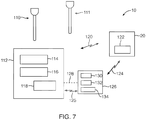
- the saliva assessment system 100 may include a swab device 110 and a measuring device 112, similar to that depicted in FIG. 1 .
- the swab device 110 may be any one of the embodiments set forth herein as a swab device.
- the measuring device 112 may include an input portion 114 and an output portion 116.
- the input portion 114 being in the form of input keys, touch screen, switch or the like.
- the output portion 116 may be in the form of a display to provide, for example, measured or weighed data, or any other relevant data.
- the measuring device 112 may also include a computing device 118 integrated therein sized and configured to send and receive data, as indicated by communication arrow 120 so as to communicate with a remote system, such as the before discussed remote database 20, as known to one of ordinary skill in the art.
- a remote system such as the before discussed remote database 20, as known to one of ordinary skill in the art.
- the swab assessment system 100 may include the remote database 20.
- the remote database 20 may be sized and configured to store data.
- the remote database 20 may include a remote computing device 122 sized and configured to receive and send data, as indicated by communication arrows 120 and/or 12.4.
- the saliva assessment system 100 may be employed with a local computing device 126, which may be integrated with the measuring device 112 (as indicated by dotted line 128) or be separate of the measuring device 112 so as to be utilized with the measuring device 112 for the user to record detail from the patient along with the measurements taken from the saliva assessment.
- the local computing device 126 may be a mobile device, such as a mobile phone, tablet or lap-top computer, or may be a stationary computer.
- the local computing device 126 includes an input device 130 and output device 132.
- the local computing device 126 may be configured, as known in the art, to send and receive data to and from the remote database, as indicated by communication arrow 124, as well as transmit to send and receive data to and from the measuring device 112, as indicated by communication arrow 125.
- Such transmissions 125 between the measuring device 112 and the local computing device 126 or the remote database 20 may be employed wirelessly or by, for example, a cable or the like, or may be transferred, for example, with a thumb drive.
- data about the patient may be input into the local computing device 126, such as an identification number, data regarding the age of the patient, the time/date, the time elapsed since the patient last slept, the time elapsed since the patient last had food and/or water, and/or any other data that may be relevant.
- the data relating to the measured amount of saliva obtained from the patient may be inputted into the local computing device 126. Such data may then be transmitted or uploaded (or transferred via, for example, a thumb drive) to the remote database as indicated by communication arrow 124.
- the data about the patient may be maintained in the measuring device 112 and/or the local computing device 126.
- the remote computing device 122 may then process the data received from the local computing device 126 and store the processed data therein, and then transmit the processed data to the local computing device 126 for the doctor to assess and provide to the patient.
- the processed data may provide the actual saliva flow rate and/or a patient saliva index number that may correspond with or be compared to a scale that may indicate a degree or level of a saliva flow of a patient to determine the degree or severity in which the patient may have the condition of dry mouth or xerostomia.
- patient saliva index number may also be associated with a unique patient identifier.
- the saliva assessment system 100 may include the remote database 20 for storing and processing data and for transmitting the processed data back to the doctor to provide detail about the severity of the condition of the patient.
- the remote database 20 continues to grow over time with patients assessed, detail regarding the data taken from the assessed patients relative to the saliva obtained may be helpful in refining the processed data and understanding what factors may be relevant relative to time of day, age, time elapsed since sleep and food eaten, male, female, medications taken/taking, health conditions, etc., to better understand saliva flow rate for a given patient. Further, as the database grows with patient data, the accumulation of multiple patients' data may generate secondary data to provide information that constitutes a standard or normalized healthy saliva flow or a normalized healthy saliva flow relative to various factors relative to, for example, cercadic fluctuations of saliva flow at certain times of day.
- the patient's data may be processed relative to the above-noted various factors and algorithmically adjusted or extrapolated to provide an adjusted saliva flow amount. Further, in this manner, upon evaluating a person's actual or adjusted saliva flow, such measurements may be evaluated relative to the accumulation of other patient's data to better understand where that evaluated person's saliva flow is in comparison to other saliva flow data and/or a normalized healthy saliva flow.
- the measuring device 112 may also be integrated with its own computing device 118.
- the measuring device 112 may be sized and configured to receive the before-discussed patient data via the input portion 114 to then transmit the data, along with the data relating to the saliva assessment, to the remote database 20.
- the remote database 20 may then store the received data and process the data to then transmit such processed data to the local computing device 126 and/or the measuring device 112 for the doctor.
- the local computing device 126 may include a local database 134.
- the local database 134 may perform the same or similar functions as that described for the remote database 20. Further, the local database 134 may work in conjunction with the remote database 20 such that the local database 1 34 may store and process data and send such data and processed data to also be stored in the remote database 20 as well as be stored in the local database 134.
- the local computing device 126 may function with the processing capabilities independent of the remote database such that the local computing device 126 may process data and store the processed data in the local database 134.
- two swab devices may be opened from their respective packaging, a primary swab device, such as swab device 110 and a secondary swab device 111 or pre-test swab device.
- the measuring device 112 may be activated by powering or turning on the measuring device 112.
- the user may then place the primary swab device 110 on the scale portion 24 by, for example, placing the proximal end 32 of the handle portion 16 of the swab device 110 in the nesting portion 26 (see FIG. 1 ).
- the user may then zero-out the measuring device 112 with the swab device 110 and nesting portion 26 positioned thereon by pressing, for example, the Tare button.
- the Tare may be automatic, such as in the case that the weight of the swab device is known.
- the patient may clear any excess saliva from the mouth. Such may be accomplished by using the tongue to gather any existing saliva in the mouth and discarding the saliva by, for example, swallowing or spitting the saliva.
- the process of clearing the excess saliva from one's mouth may include employing, for example, a suction device.
- the process of clearing excess saliva from one's mouth may also include inserting the secondary swab device 111 (the swab device not positioned on the measuring device) into the mouth to further absorb any additional excess saliva.
- the secondary swab device 111 may be placed under the tongue and, upon closing the mouth, pressing down on the swab portion with the tongue for a period of time, such as one second or more.
- the secondary swab device 111 may be placed under the tongue for a time period ranging between about one second and three seconds, or ranging between about one second and five seconds, or ranging between about one second and ten seconds.
- the secondary swab device 111 may be placed under the tongue for about three seconds. In still another embodiment, the secondary swab device 111 may be placed under the tongue for a time period ranging between about one second and about twenty seconds. In this manner, the excess saliva may be cleared or removed from one's mouth. The secondary swab device 111 may then be discarded.
- the patient may maintain their mouth in a closed position for a first predetermined period of time, such as 60 seconds.
- the first predetermined period of time may be in the range of about 15-90 seconds, or about two minutes or about three minutes or any suitable period of time, such as five minutes, so long as the first predetermined period of time is provided as data relative to the saliva sample obtained from the patient.
- the first predetermined period of time may be about 60 seconds.
- the patient may tilt his or her head forward slightly with the tongue pressed against the roof of the mouth so that new saliva produced from the saliva glands in the mouth may pool below the patient's tongue.
- the patient may grasp the primary swab device 110 positioned on the measuring device so that immediately after the first predetermined period has lapsed, the patient can place the swab portion of the primary swab device 110 under the tongue in the mouth to collect the accumulated saliva by pressing down onto the swab with the tongue for a second predetermined period of time, such as about three seconds.
- the second predetermined period of time may range between about 1 second and about 3 seconds.
- the second predetermined period of time may range between about 1 second and about 5 seconds. In still another embodiment, the second predetermined period of time may range between about 1 second and about 10 seconds.
- the primary swab device 110 with the absorbed saliva may be positioned on the measuring device 112 by, for example, inserting the proximal end 32 of the swab device into the nesting portion 26 of the measuring device 112 (see FIG.1 ).
- the measuring device 112 may then display, for example, the weight of the saliva collected in the swab portion of the primary swab device 110. This displayed weight value may then be recorded and the swab device 110 discarded.
- the data received from the patient may then be processed to obtain processed data to compare and determine a degree or level of the condition of the patient relative to dry mouth or xerostomia, as previously described. Further, as previously set forth, in one embodiment, such patient data may be transmitted to the remote database 20 to be processed and to obtain the processed data for the patient.
- the above-noted procedure may be completed a second time or multiple consecutive times within a given hour or day to take additional samples for the purpose of obtaining average flow rate detail or the like, or to obtain additional information of saliva flow rate relative to different times of the day to better understand a given person's saliva flow rate relative to, for example, potential cercadic fluctuations of the person.
- the secondary swab device 111 or pre-test swab device may be employed prior to using the primary swab device 110 to perform pre-testing to determine if further testing should be completed by the person being tested.
- pre-testing may include the steps of clearing saliva from the mouth, such as by spitting or swallowing the excess saliva from one's mouth.
- the person may insert a swab device, such as the pre-test swab device or secondary swab device 111 for a predetermined period of time or pre-test predetermined period of time.
- This pre-test predetermined period of time may range between about 1 second and about 20 seconds, or about 1 second and about 10 seconds, or any suitable period of time.
- the pre-test swab may be placed under the person's tongue. Subsequent the pre-test period of time, the person may remove the pre-test swab and then measure the amount of saliva captured by the pre-test swab by positioning the pre-test swab device on the measuring device 112. Upon determining the amount of saliva captured by the pre-test swab for the pre-test predetermined period of time, such saliva amount may be compared with a standard healthy saliva amount.
- the person may stop in being further tested. If the saliva amount obtained is less than the standard healthy saliva amount, then the person may undergo further testing. For example, the person may then undergo the testing procedure of clearing excess saliva from the mouth, maintaining the mouth in a closed position for a predetermined period of time, such as ranging between about 3 seconds and about 90 seconds, inserting the primary swab 110 into the mouth for another predetermined period of time, such as ranging between about 1 second and about 20 seconds, and then measuring the amount of saliva captured by the primary swab 110 by positioning the primary swab on the measuring device 112 to obtain, for example, a weight of the saliva captured by the primary swab 110. As previously set forth, the various patient data and results of the testing may then be recorded to the remote database 20 and/or the local computing device 126.
- a predetermined period of time such as ranging between about 3 seconds and about 90 seconds
- inserting the primary swab 110 into the mouth for another predetermined period of time such as ranging between about 1 second and
- the swab device 140 of this embodiment may be employed, for example, when taking saliva samples from a large number of patients.
- the swab device 140 of this embodiment may include a case 142 or container and a swab portion 144, the swab portion 144 being coupled to the case 142 and enclosable within the case 142.
- the case 142 may be formed from a polymeric material, as known to one of ordinary skill in the art.
- the case 142 may include a first case portion 146 that may be pivotably coupled to a second case portion 148 in a clam shell arrangement.
- first and second case portions 146, 148 may be coupled with a hinge 150. In another embodiment, the first and second case portions 146, 148 may be coupled with a living type hinge. With this arrangement, the case 142 may be moved between a closed position ( FIG. 10 ) and an open positon ( FIGS. 8 and 9 ). Further, as set forth, the first and second case portions 146, 148 may be sized to hold the swab portion 144 therein. As such, the shape and size dimensions of the first and second case portions 146, 148 may correspond with the sizing of the swab portion 144 and, in another embodiment, any additional components that may be coupled to the swab portion, such as a handle component.
- the swab portion 144 may exhibit a flat configuration with a rectangular periphery.
- the swab portion 144 may include a first portion 152 and a second portion 154 defined by dotted lines 156.
- the first portion 152 of the swab portion 144 may be adhesively coupled to an inner surface of the first case portion 146.
- the second portion 154 of the swab portion 144 may be freely lifted or moveable relative to the first case portion 146, as depicted in FIG. 9 .
- the swab portion 144 upon opening the case 142, the swab portion 144 may be biased to extend outward at an angle 159 relative to the first case portion with, for example a biasing element 158 or the like.
- one of the first case portion 146 or the second case portion 148, or both may act as a handle portion for the swab device 140.
- a patient may open the case 142, as depicted in FIG. 9 , to position the swab portion 144 in his or her mouth for the before-discussed second predetermined period of time to absorb the accumulated saliva (after undergoing the procedure of accumulating saliva in the mouth for a first predetermined period of time, as discussed above).
- the swab portion 144 may be removed from the mouth and the case 142 moved to the closed position, as depicted in FIG. 10 .
- the case 142 may be maintained in its closed position with a snap type lock. In another embodiment, in the closed position, the case 142 may be configured to be substantially sealed with the swab portion 144 therein. In still another embodiment, the outer surface 160 of the case 142 may be marked with data detail of the patient, for example, a patient identification number and any other relevant patient data, as indicated by indicia 162.
- the swab device 140 with the case 142 may be weighed to determine the saliva amount or saliva flow rate or the like, similar to that discussed in previous embodiments. With this arrangement, the swab device 140 with the case 142 facilitates administering a saliva flow rate assessment to a large volume of patients or in circumstances where the measuring device 112 ( FIG. 7 ) may not be readily available in the patient's room.
- the swab device 170 may include a case 172 and a swab portion 174 similar to the previous embodiment such that the case 172 is moveable between an open position, as depicted in FIG. 11 , and a closed position, similar to FIG. 10 of the previous embodiment.
- the case 172 may include a first case portion 176 and a second case portion 178.
- the swab portion 174 may include an intermediate member or handle 180 with a swab 182 at a distal end of the handle 180.
- the handle 180 may be coupled to a portion of the case 172, such as the first case portion 176, at a proximal end of the handle 180. In another embodiment, the handle 180 may be coupled to or adjacent the hinge between the first and second case portions 176, 178.
- the swab 182 may include a similar shape as the swab portion described and depicted relative to FIG. 2 , or any of the embodiments set forth herein. Further, in this embodiment, upon the case 172 being moved to an open position, the handle 180 may be moveable to an orientation or an angle that extends outward relative to the first case portion 176, similar to that depicted in FIG. 9 .
- a patient may readily grasp the handle and/or at least one of the first and second portions 176, 178 and position the swab in his or her mouth to collect a saliva sample, employing a similar procedure for collecting the saliva sample described in previous embodiments.
- the case 172 may then be moved to the closed position for later weighing of the saliva sample.
- FIG. 12 is another embodiment of a swab device 190 that may include a handle portion 192 and a swab portion 194, the handle portion 192 being similar to previous embodiments as depicted in FIGS. 2 and 5 .
- the swab portion 194 may include an upper portion 196 and a lower portion 198 with a proximal extension 200 coupling the upper and lower portions 196, 198.
- the upper and lower portions 196, 198 may define an opening 202 therebetween such that the opening is on a distal side 204 of the swab portion 194.
- Such opening 202 may be in the form of a gap or channel or the like and may be sized and configured to receive the tongue of the patient.
- the lower portion 198 may absorb saliva that may collect under the tongue and the upper portion 196 may absorb saliva above the tongue and adjacent the cheek regions.
- FIG. 13 another embodiment of a swab device 210 that may include a handle portion 212 and a swab portion 214 is depicted.
- This embodiment is similar to the previous embodiment such that the swab portion 214 defines an opening 216 on a distal side 218 of the swab portion 214 that may be sized and configured to receive the tongue of the patient.
- the swab portion 214 may be somewhat block-like but may define any other suitable shape.
- a swab device 220 may include a handle portion 222 and a swab portion 224.
- the handle portion 222 in this embodiment may be similar to the previous embodiments as depicted in FIGS. 2 and 5 .
- the handle portion 222 may be straight (without the bend or curve along the distal handle portion).
- the swab portion 224 may be sized and configured to receive at least a portion of the teeth of the patient.
- the swab portion may define a top surface 226 and a bottom surface 228 each defining a curved channel 230 therein, the curved channel sized and configured to receive the patient's teeth.
- FIG. 15 another embodiment of a swab device 240 with a handle portion 242 and a swab portion 244 is provided.
- This embodiment may include structural features similar to the embodiments of FIGS. 13 and 14 .
- the swab device 240 of this embodiment may include a top surface 246, a bottom surface 248, and a distal surface 250, each of which may define structure for receiving the teeth and tongue of the patient.
- the top surface 246 and the bottom surface 248 of the swab portion 244 may each define a curved channel 252 therein for receiving respective upper and lower teeth of the patient.
- the distal surface 250 of the swab portion 244 may define an opening 254 therein sized and configured to receive the tongue of the patient.
- the swab device 240 of this embodiment may be configured to collect saliva at multiple locations within the patient's mouth.
- a swab device 260 with a handle portion 262 and a swab portion 264 is provided.
- the handle portion 262 may be straight.
- the swab portion 264 may be elongated with a curve along a length thereof.
- the swab portion 264 may include a top surface 268 and a bottom surface 270 such that the top surface 268 may define a convex feature 276 from a proximal end 272 to a distal end 274 and the bottom surface 270 may define a concave feature 278 from the proximal end 272 to the distal end 274.
- the swab portion 264 of this embodiment may be sized and configured to be placed within the patient's cheek to capture saliva produced, for example, from the parotid glands. It should be noted that the swab portion 264 may be positioned to be oriented so that the top surface 268 is positioned against the inner surface of the cheek. In another embodiment, only the top surface 268 or only the bottom surface 270 exhibits either a convex or concave feature.
- the swab device 280 may include a handle portion 282 and a swab portion 284.
- the handle portion 282 may be a straight handle, best shown in FIG. 17A .
- the swab portion 284 may be in block form or the like.
- the swab portion 284 may be sized and configured to be positioned in the cheek of the patient for absorbing saliva from the parotid glands, for example. It should be noted that the handle portion 282 of this embodiment may be employed with any of the swab device embodiments described herein.
- any one of the swab devices described herein may include an electrical sensor associated therewith.
- the electrical sensor may sense when a swab portion has absorbed saliva to a particular capacity, such as 80% or 90%. Otherwise said, the sensor may sense to the user once the swab portion has been saturated to, for example, 80% or 90%.
- the swab device may also include an indicator element configured to indicate to the user once the swab portion has absorbed saliva to a particular capacity. Such indicator element may be in the form of a light and/or a beeping noise.
- the volume of saliva will be known for a given swab portion at the particular capacity, set forth above, as well as the time period taken to absorb the saliva to the particular capacity or saturation level.
- the swab device of this embodiment that includes a sensor may be employed to assess a saliva flow rate.
- a saliva assessment system 300 may include a swab device 302 and a measuring device 304 that may be employed to function similarly to the saliva assessment system embodiments described and depicted relative to FIGS. 1 and 7 .
- the methods and systems described in previous embodiments for a saliva assessment system may be employed with the saliva assessment system 300 of this embodiment.
- the swab device 302 may he moved between a non-engaged position and an engaged position relative to the measuring device 304, the engaged position (see FIG.
- the measuring device 304 of this embodiment may include a scale portion 308, an input 310 and an output 312.
- the input 310 may be in the form of key pads and a touch sensitive screen 314 integrated with a display 316.
- the output 312 may also be in the form of the display 316, for displaying various data, such as a weight of the saliva collected with the swab device 302, patient data, and/or cumulative or comparative patient data.
- the measuring device 304 may include a base portion 318 disposed below a platform portion 320 and an upstanding portion 322, the upstanding portion 322 extending upward from a rear portion 324 of the base portion 318.
- the upstanding portion 322 may include the display 316 along a front side 326 of the upstanding portion 322 and the measuring device 304.
- the platform portion 320 may include an upper surface 328 that extends flat or horizontally level above the base portion 318 along the front side 326 of the measuring device 304.
- the platform portion 320 may include a power button 330 or power switch disposed thereon. Such power button 330 or power switch may be at alternative locations on the measuring device 304.
- the measuring device 304 of this embodiment may be sized and configured to communicate with a remote database 20 and/or a local computing device 126, similar to that described and depicted relative to FIG.7 .
- the platform portion 320 may also extend to and define the scale portion 308, the scale portion 308 defining holding structure 332, such as the nesting portion 306, sized and configured to receive the swab device 302 for weighing saliva collected with the swab device 302.
- the nesting portion 306 may be in the form of a recess 334 defined in the upper surface 328 of the platform portion 320, the recess 334 being sized and configured to receive a proximal most end of the swab device 302 so as to nest together in a nesting arrangement.
- the recess 334 may be defined with side walls 336 extending downward to a bottom surface 338.
- the bottom surface 338 of the scale portion 308 being the surface for placing the swab device 302 for measuring purposes, similar to that described in previous embodiments herein.
- the swab device 302 may include a handle portion 340 and a swab portion 342.
- the handle portion 340 may extend between a first end 344 and a second end 346, the first end 344 being a proximal end and the second end 346 being a distal end.
- the handle portion 340 may include a base 348 or platform fixedly coupled to the first end 344. Such base 348 may be the proximal most end of the swab device 302.
- the base 348 may include an underside base surface 350 and an upper base surface 352 with peripheral side walls 354 defined therebetween.
- the peripheral side walls 354 may extend upward between the underside and upper base surfaces 350, 352 such that the base 348 may exhibit a low profile or somewhat flat profile.
- the underside and upper base surfaces 350, 352 may extend to exhibit a generally square shape with rounded corners.
- such base 348 may be sized and configured to correspond with the peripheral shape defined by the side walls 336 of the recess 334 of the scale portion 308 of the measuring device 304 such that the peripheral side walls 354 extend to be sized slightly smaller than the periphery of the recess 334 (see FIGS. 18 and 19 ).
- the base 348 of the swab device 302 may be inserted within the recess 334 of the measuring device 304 such that the swab device 302 may sit erect within the recess 334 of the measuring device 304 (see FIG. 19 ).
- the underside base surface 350 of the base 348 may be planar so that the swab device 302 may be positioned on any flat surface to sit upright and maintain an upright erect orientation.
- the scale portion 308 may define a nesting portion sized and configured to receive the handle portion 340 of the swab device 302 so that the handle portion 340 may nest and be positioned in a generally horizontal position or tilted upward from a generally horizontal position.
- the first end 344 of the handle portion 340 may extend directly from the upper base surface 352 of the base 348.
- the handle portion 340 may include a handle 362 and a distal portion 364 extending along a longitudinal length 356, the length 356 extending with a width 358 (see also FIG. 21 ) and a depth 360 thereof.
- the dimension of the width 358 may be larger than the dimension of the depth 360, and the dimension of the length 356 may be greater than the dimensions of the width 358 and the depth 360.
- the depth 360 dimension may taper along a portion of the length 356 of the handle portion 340, such as to define a tapered portion 366. Such tapered portion 366 may extend along a transition between the handle 362 and the distal portion 364 of the handle portion 340.
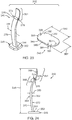
- the longitudinal length 356 of the handle portion 340 may extend with one or more curves 368. In one embodiment, the handle portion 340 may extend with two primary curves so as to exhibit an s-type profile (see FIG. 24 ). Further, the handle portion 340 may define a first surface 370 and a second surface 372 defined along the width 358, the first surface 370 facing opposite relative to the second surface 372 with the depth 360 dimension extending between the first and second surfaces 370, 372.
- the distal portion 364 of the handle portion 340 may include a first protrusion 374 extending from the first surface 370 and a second protrusion 376 extending from the second surface 372, the first protrusion 374 extending directly opposite the second protrusion 376. Further, the first and second protrusions 374, 376 may be elongated to extend along the width 358 of the handle portion 340. In one embodiment, the first and second protrusions 374, 376 may extend with an enlarged end portion 378. In another embodiment, the first and second protrusions 374, 376 with the enlarged end portion 378 may exhibit a mushroom type profile, as depicted in FIG. 24 .
- the swab portion 342 of the swab device 302 may be similar to the swab portion described in previous embodiments herein.
- the swab portion 342 may be sized and configured to be coupled to the distal portion 364 of the handle portion 340 of the swab device 302.
- the swab portion 342, in a relaxed position, may be a generally flat flexible and resilient structure, as depicted in FIG. 23 .
- the swab portion 342 may extend in a generally oval configuration with an elongated length 380, a width 382, and a depth 384 of the swab portion 342.
- the swab portion 342 may define a first side surface 386 and a second side surface 388 with a periphery 389 therebetween, the periphery 389 defining the depth of the swab portion 342.
- the swab portion 342 may extend along its length 380 to define opposite first and second end portions 390, 391 with an intermediate portion 392 therebetween.
- the first side surface 386 may define a first slit 393 and a second slit 394 in the respective opposite first and second end portions 390, 391 thereof.
- the first and second slits 393, 394 may extend through the depth 384 of the swab portion 342 between the first and second side surfaces 386, 388. Further, the first and second slits 393, 394 may be oriented to extend transverse relative to the elongated length 380 of the swab portion 342 and may be sized and configured to receive the first and second protrusions 374, 376 of the handle portion 340 to facilitate coupling the swab portion 342 to the handle portion 340. As depicted in FIGS.
- the swab portion 342 may be assembled to the handle portion 340 by wrapping or folding the swab portion 342 over the second end 346 or distal end of the handle portion 340 so that the swab portion 342 exhibits a bowed position or bowed configuration around the distal end of the handle portion 340.
- Such bowed position of the swab portion 342 may be a constrained position of the swab portion 342.
- first and second slits 393, 394 defined in the opposite first and second end portions 390, 391 of the swab portion 342 may facilitate coupling the swab portion 342 to the respective first and second protrusions 374, 376 of the handle portion 340.
- the opposite first and second end portions 390, 391 may be held against the opposite first and second surfaces 370, 372 of the handle portion 340 with a portion 396 of the swab portion 342 bowed away or out from one or both of the first and second surfaces 370, 372 adjacent the second end 346 of the handle portion 340.
- the tapered down and more slender profile of the distal portion 364 of the handle portion 340 may be somewhat flexible.
- the swab device 302 may be employed for capturing the saliva within the pours of the swab portion 342 upon the user positioning the swab portion 342 under the tongue.
- a swab device may include a handle portion with an integrated scale for determining a weight of the saliva collected with the swab portion.
- a handle portion of a swab device with, for example, an integrated scale may also include an integrated computing device that may be configured to transmit data to the local computing device 126 and/or the remote database 20 ( FIG. 7 ).
- the swab device 302 may include a strip (not shown) or the like associated with the swab device 302, such as on the swab portion 342, or on the handle portion 340 adjacent the swab portion 342, or a strip included with the system 300 that may measure a pH level of the saliva from the mouth.
- the swab portion 342 itself may include an indicator or strip or the like that may indicate a pH level of the saliva from the mouth. In this manner, upon assessing the saliva flow of a person, the pH level of the saliva may also be assessed.
Landscapes
- Health & Medical Sciences (AREA)
- Life Sciences & Earth Sciences (AREA)
- General Health & Medical Sciences (AREA)
- Veterinary Medicine (AREA)
- Public Health (AREA)
- Animal Behavior & Ethology (AREA)
- Engineering & Computer Science (AREA)
- Pathology (AREA)
- Biomedical Technology (AREA)
- Heart & Thoracic Surgery (AREA)
- Medical Informatics (AREA)
- Molecular Biology (AREA)
- Surgery (AREA)
- Hematology (AREA)
- Biophysics (AREA)
- Physics & Mathematics (AREA)
- Gastroenterology & Hepatology (AREA)
- Endocrinology (AREA)
- Physiology (AREA)
- Pulmonology (AREA)
- Dentistry (AREA)
- Pharmacology & Pharmacy (AREA)
- Oral & Maxillofacial Surgery (AREA)
- Chemical & Material Sciences (AREA)
- Analytical Chemistry (AREA)
- Clinical Laboratory Science (AREA)
- Chemical Kinetics & Catalysis (AREA)
- Investigating Or Analysing Biological Materials (AREA)
- Sampling And Sample Adjustment (AREA)
Description
- The present invention relates generally to xerostomia or reduced saliva flow and, more specifically, the present invention relates to devices, systems and methods for assessing saliva flow.
- Dry mouth, also known as xerostomia, is the medical term for the subjective complaint of having a dry mouth or lack of saliva. Dry mouth can lead to problems of tooth decay, the ability to swallow, and the ability to taste and digest food, among other things. Physicians and dentists continue to seek diagnostic devices and methods for determining or assessing the condition of xerostomia or dry mouth by measuring a saliva flow rate produced by the glands in the mouth. The apparent most widely used method for determining saliva flow rate within a patient is by conducting a drool test. For example, the drool test is implemented with a drool cup, in which a patient leans over the cup with his or her head tilted forward and the mouth open to allow drool produced by the saliva glands to flow over the bottom lip and into the drool cup. Such test is typically timed over a five or ten minute time period. At the end of the time period, a saliva flow rate may be determined by the amount of saliva collected into the drool cup relative to the time period taken to collect the saliva. This known method for determining saliva flow rate for a given person has often been found to be inaccurate due to the difficulty in conducting the test and the close supervision and patient compliance required. Further, the drool test is inefficient since the typical time frame just to collect the saliva sample is five to ten minutes. Furthermore, from a patient's standpoint, drooling into a cup is degrading, humiliating, cumbersome and uncomfortable, especially when conducted with staff, doctors and/or family members present.
- Based on the foregoing, it would be advantageous to provide a device, system and/or method that substantially overcomes the above-noted limitations for determining a patient's saliva flow rate and related data.
-
US 2015/0216471 A1 discloses detection of one or more fronts of saliva advancing simultaneously in multiple directions may be used to determine salivary secretion rate, as may be indicative of state of euhydration or dehydration. An array of electrical contacts may be arranged between a substrate and a liquid collection element, and used to detect saliva migrating through the liquid collection element. A substrate may include a leading edge defining a notch or recess to receive a sublingual frenulum for positioning a liquid collection element proximate to a sublingual salivary duct, or may include a flexible substrate for positioning a liquid collection element in an oral cavity proximate to at least one parotid or minor salivary duct. Sensing of salivary flow rate may be augmented by measuring concentration of at least one analyte in saliva and/or sensing various environmental factors. Groups of electrical contacts may be arranged proximate to different salivary glands or ducts. - The following documents were also cited during examination of the present application:
US4966241 ,US 2002/038567 ,US 2009/024060 andUS 2002/155029 . - The present invention is directed to various embodiments of devices, systems and methods for assessing saliva flow from saliva glands in a mouth of a person, such as a patient. In one embodiment, a saliva assessment system for measuring saliva flow in a mouth of a person is provided. The saliva assessment system comprises the features defined in claim 1. Preferred embodiments are defined in the dependent claims.
- In another embodiment, the swab device includes a base structure at the proximal end of the handle portion, the base structure sized and configured to nest with the nesting portion of the measuring device such that the swab device is positionable with the nesting portion in an erect manner. In another embodiment, the handle portion extends with a first surface and a second surface along a longitudinal length of the handle portion, the first surface facing opposite relative to the second surface. The distal portion of the handle portion includes a first protrusion and a second protrusion positioned to extend from the first surface and the second surface, respectively, the first and second protrusions configured to facilitate coupling the swab portion to the handle portion.
- In still another embodiment, the swab portion extends with an elongated flat structure having a first end portion and a second end portion, the elongated structure folded over the distal end of the handle portion so to cover opposite sides of the distal portion of the handle portion. In a further embodiment, the swab portion defines a first slit and a second slit in the first end portion and the second end portion, respectively, the first slit sized and configured to couple to a first protrusion extending from the handle portion and the second slit sized and configured to couple to a second protrusion extending from the handle portion.
- In another embodiment, the handle portion of the swab device extends with one or more curves along a length of the handle portion. In yet another embodiment, the swab portion includes at least one of a foam material, a fabric material, and a natural fiber material, the swab portion configured to absorb the saliva from the mouth. In another embodiment, the measuring device includes a scale portion integrated adjacent the nesting portion of the measuring device, the scale portion configured to measure a weight of the saliva captured by the swab portion.
- In another embodiment, the measuring device includes an integrated computing device, the integrated computing device being operatively coupled to at least one of a remote database and a local computing device, each of the at least one of the remote database and the local computing device being configured to receive and store patient data received from the integrated computing device and process the patient data, the at least one of the remote database and the local computing device configured to send processed patient data to the integrated computing device of the measuring device. In a further embodiment, the processed patient data includes a patient data index number.
- In another embodiment, the system further includes a local computing device for entering patient data obtained from the measuring device, the local computing device being operatively coupled to a remote database, the remote database configured to receive and store the patient data and process the patient data, the remote database configured to send the processed patient data to the local computing device. In a further embodiment, the processed patient data includes a patient data index number. In another embodiment, the measuring device is operatively coupled to a local computing device, the local computing device configured to transmit to and receive data from at least one of a remote database and the measuring device.
- In accordance with another non-claimed embodiment of the present disclosure a swab device configured to measure saliva flow in a mouth of a person is provided. The swab device includes a handle portion and a swab portion. The handle portion extends between a proximal end and a distal end to define an elongated structure along a length thereof. The handle portion includes a flat base structure at the proximal end of the handle portion, the flat base structure extending transverse relative to the elongated structure of the handle portion. The swab portion is coupled to a distal portion of the handle portion, the swab portion being sized and configured to collect saliva from the mouth.
- In another embodiment, the handle portion defines a width and a depth, the depth being smaller than the width of the handle portion, the width extending with a first surface and an oppositely facing second surface along the length of the handle portion. In another embodiment, the handle portion extends with a first surface and a second surface along the length of the handle portion, the first surface facing oppositely relative to the second surface. The distal portion of the handle portion includes a first protrusion and a second protrusion positioned to extend from the first surface and the second surface, respectively, such that the swab portion is coupled to the first and second protrusions.
- In another embodiment, the swab portion extends with a flat elongated sheet structure having a first end portion and a second end portion, the elongated structure folded over the distal end of the handle portion so that the first and second end portions couple to opposite sides of the distal portion of the handle portion. In still another embodiment, the swab portion defines a first slit and a second slit in the first end portion and the second end portion, respectively, of the flat elongated sheet structure, the first and second slits configured to couple to the opposite sides of the distal portion of the handle portion.
- In another embodiment, the handle portion of the swab device extends with one or more curves along a length of the handle portion. In yet another embodiment, the handle portion includes a tapered portion along a length of the handle portion.
- In still another embodiment, the swab portion includes at least one of a foam material, a fabric material, and a natural fiber material. In another embodiment, the swab portion is a flat sheet structure folded over the distal end of the handle portion so that the flat sheet structure exhibits a bowed portion.
- In accordance with another embodiment of the present invention, a method for measuring saliva flow is provided. The method includes the steps defined in
claim 12. Preferred embodiments are defined in the dependent claims. - In another embodiment, the method further includes comparing the measured amount of saliva with a standard healthy saliva amount to determine whether to continue testing the saliva flow of the person. In still another embodiment, the method further includes determining whether the measured amount of saliva is below a standard healthy saliva amount. In another embodiment, the method further includes: maintaining the mouth in a closed position for a second predetermined period of time ranging between about 3 second and about 90 seconds; inserting a second swab into the mouth for a third predetermined period of time ranging between about 1 second and about 20 seconds; and measuring an amount of saliva captured by the second swab by positioning the second swab on the measuring device.
- In accordance with another non-claimed embodiment of the present disclosure a method for measuring saliva flow in a mouth of a person is provided. The method includes the steps of: clearing excess saliva from the mouth; maintaining the mouth in a closed position for a first predetermined period of time ranging between about 3 seconds and about 90 seconds; inserting a swab into the mouth for a second predetermined period of time ranging between about 1 second and about 20 seconds; and measuring an amount of saliva captured by the swab by positioning the swab on a measuring device. 6.
- In another embodiment, subsequent to the step of clearing, the method includes the steps of: inserting a pre-test swab into the mouth for a pre-test predetermined period of time ranging between about 1 second and about 20 seconds; measuring an amount of saliva captured by the pre-test swab by positioning the pre-test swab on the measuring device; and determining whether the measured amount of saliva by the pre-test swab is below a standard saliva amount to warrant proceeding with the maintaining step.
- In another embodiment, the inserting step includes inserting the swab for the second predetermined period of time that ranges between about 1 second and about 10 seconds. In another embodiment, the inserting step includes inserting the swab for the second predetermined period of time that ranges between about 1 second and about 5 seconds. In another embodiment, the inserting step comprises inserting the swab for the second predetermined period of time that ranges between about 1 second and 3 seconds. In still another embodiment, the inserting step includes inserting the swab for the second predetermined period of time of about 3 seconds. In yet another embodiment, the maintaining step includes maintaining the mouth in the closed position for about 60 seconds for the first predetermined period of time.
- In another embodiment, the clearing step includes clearing the excess saliva by inserting a secondary swab in the mouth for a period of time ranging between about 1 second and 5 seconds. In still another embodiment, the clearing step includes clearing the excess saliva by inserting a portion of a secondary swab in the mouth for a period of time of about 3 seconds.
- In another embodiment, the measuring step includes positioning a proximal end of a handle of the swab in an aperture defined in structure disposed above the measuring device. In another embodiment, the measuring step includes weighing the swab to determine a weight of the saliva.
- In still another embodiment, the inserting step includes inserting the swab having a handle portion and a swab portion such that the swab portion includes a hydrophilic foam configured to absorb fluid. In another embodiment, the inserting step includes inserting the swab having a handle portion and a swab portion such that the swab portion includes a reticulated foam material configured to absorb fluid. In yet another embodiment, the inserting step includes inserting the swab having a handle portion and a swab portion, the swab portion extending in a flat configuration with a distal peripheral edge and a proximal peripheral edge, the distal peripheral edge extending substantially linearly and the proximal peripheral edge extending radially.
- In accordance with another non-claimed embodiment of the present disclosure a saliva assessment system for measuring saliva flow in a mouth of a person is provided. The saliva assessment system includes a swab device and a measuring device. The swab device is sized and configured to be placed in the mouth such that the swab device includes a handle portion and a swab portion. The handle portion extends between a proximal end and a distal end, the distal end coupled to the swab portion. The swab portion extends with a flat configuration to define a peripheral edge. The peripheral edge extending along a distal peripheral edge and a proximal peripheral edge, the distal peripheral edge extending linearly and the proximal peripheral edge extending radially. The measuring device is sized and configured to measure an amount of the saliva collected in the swab portion from the mouth. Further, the measuring device includes a nesting portion coupled thereto. The nesting portion defines an aperture therein, the aperture sized and configured to receive a proximal end of the handle portion of the swab device.
- In another embodiment, the swab portion exhibits a half oval configuration sized and configured to be positioned under a tongue in the mouth. In another embodiment, the measuring device includes a scale portion configured to measure a weight of the saliva captured by the swab portion. In another embodiment, the handle portion extends with a curve along a distal portion of the handle portion.
- In another embodiment, the swab portion includes a hydrophilic material configured to absorb fluid. In another embodiment, the swab portion includes a polymeric material configured to absorb fluid. In still another embodiment, the swab portion includes a reticulated material configured to absorb fluid. In yet another embodiment, the swab portion includes a foam material configured to absorb fluid. In another embodiment, the swab portion includes a fabric material configured to absorb fluid. In another embodiment, the swab portion includes a reticulated, hydrophilic polyurethane foam material configured to absorb fluid.
- In another embodiment, the measuring device includes an integrated computing device, the integrated computing device being operatively coupled to a remote database configured to receive and store patient data received from the integrated computing device and process the patient data. Such remote database is configured to send processed patient data to the integrated computing device of the measuring device. In another embodiment, the processed patient data may include a patient data index number.
- In another embodiment, the system further includes a local computing device for entering patient data, the local computing device being operatively coupled to a remote database. Such remote database is configured to receive and store the patient data and process the patient data such that the remote database is configured to send the processed patient data to the local computing device. In another embodiment, the processed patient data includes a patient data index number.
- In accordance with another non-claimed embodiment of the present disclosure a swab device configured to measure saliva flow in a mouth of a person is provided. The swab device includes a handle portion and a swab portion. The handle portion extends between a proximal end and a distal end thereof. The swab portion is coupled to the distal end of the handle portion. The swab portion extends in a flat configuration to define a peripheral edge, the peripheral edge extending to define a distal peripheral edge and a proximal peripheral edge. The distal peripheral edge extends substantially linearly and is configured to be positioned under a tongue in the mouth and adjacent a rear side thereof. The proximal peripheral edge extends radially and is configured to be positioned under the tongue and adjacent an inner surface of bottom teeth in the mouth.
- In another embodiment, the swab portion includes a hydrophilic material configured to absorb liquid. In another embodiment, the swab portion includes a polymeric material configured to absorb liquid. In still another embodiment, the swab portion includes a reticulated material configured to absorb liquid. In yet another embodiment, the swab portion includes a foam material configured to absorb liquid. In another embodiment, the swab portion includes a fabric material configured to absorb liquid. In another embodiment, the swab portion includes a hydrophilic polyurethane foam material configured to absorb liquid. In still another embodiment, the handle portion extends with a curve along a distal portion of the handle portion.
- In accordance with another non-claimed embodiment of the present disclosure a swab device configured to measure saliva flow in a mouth of a person is provided. The swab device includes a case and a swab portion. The case includes a clam shell arrangement with a first case portion and a second case portion. The first case portion is pivotably coupled to the second case portion such that the case is moveable between an open position and a closed position. The swab portion is coupled to an inner surface of at least one of the first case portion and the second case portion of the case. Upon the case being in the closed position, the swab portion is sized and configured to be enclosed in the case. Further, upon the case being moved to the open position, at least one of the first case portion and the second case portion are sized and configured to facilitate handling the swab portion to position the swab portion within the mouth.
- In another embodiment, upon the case being in the closed position, the first case portion substantially seals with the second case portion. In another embodiment, the first case portion and the second case portion are maintainable in the closed position with a snap type fit. In another embodiment, the swab portion includes a handle coupled to the case. In still another embodiment, the swab portion is moveable to be oriented at an angle relative to the inner surface of one of the first and second case portions of the case. In another embodiment, the first case portion is pivotably coupled to the second case portion with at least one of a hinge and a living hinge.
- In another embodiment, the swab portion includes a hydrophilic material configured to absorb fluid. In another embodiment, the swab portion includes a polymeric material configured to absorb fluid. In still another embodiment, the swab portion includes a reticulated material configured to absorb fluid. In yet another embodiment, the swab portion includes a foam material configured to absorb fluid. In another embodiment, the swab portion includes a fabric material configured to absorb fluid. In another embodiment, the swab portion includes a reticulated, hydrophilic polyurethane foam material configured to absorb fluid.
- In accordance with another non-claimed embodiment of the present disclosure a saliva assessment system for measuring saliva flow in a mouth of a person is provided. The saliva assessment system includes a swab device and a measuring device. The swab device is sized and configured to be placed in the mouth, the swab device having a handle portion and a swab portion. The handle portion extends between a proximal end and a distal end, the distal end coupled to the swab portion. The measuring device is sized and configured to measure an amount of the saliva collected on the swab portion from the mouth.
- In one embodiment, the swab portion includes an upper portion and a lower portion with a proximal extension therebetween, the swab portion defining a gap between the upper portion and the lower portion on a distal side of the swab portion such that the gap is sized and configured to receive a tongue of the person. In another embodiment, the swab portion includes a distal side, the distal side defining an opening therein, the opening sized and configured to receive a tongue of the person. In another embodiment, the swab portion includes a top surface and a bottom surface each defining a curved channel therein, the curved channel sized and configured to receive respective upper and lower teeth of the person. In still another embodiment, the swab portion includes an upper surface, a bottom surface, and a distal surface. The upper and bottom surfaces define curved channels therein sized and configured to receive teeth of the patient. The distal surface defines an opening therein sized and configured to receive a tongue of the person. In yet another embodiment, the swab portion includes an elongated curved structure. In still another embodiment, the swab device includes a straight handle.
- In another embodiment, the swab portion includes a natural fiber configured to absorb liquid. In another embodiment, the swab portion includes a polymeric material configured to absorb liquid. In still another embodiment, the swab portion includes at least one of a foam material, a fabric material, and a natural fiber material. In another embodiment, the measuring device is a digital scale. In still another embodiment, the measuring device is a vibration measuring device. In still another embodiment, the measuring device is an optical measuring device.
- The foregoing and other advantages of the invention will become apparent upon reading the following detailed description and upon reference to the drawings in which:
-
FIG. 1 is a front view of a saliva assessment system, depicting a swab device and a measuring device, according to one embodiment of the present invention; -
FIG. 2 is a perspective view of the swab device, according to another embodiment of the present invention; -
FIG. 3 is a side view of the swab device, according to another embodiment of the present invention; -
FIG. 4 is a top view of a swab portion, depicting the swab portion in a preformed state, according to another embodiment of the present invention; -
FIG. 5 is a perspective view of another embodiment of a swab device, according to the present invention; -
FIG. 6 is a side view of the swab device ofFIG. 5 , according to another embodiment of the present invention; -
FIG. 7 is a schematic view of a saliva assessment system, according to another embodiment of the present invention; -
FIG. 8 is a perspective view of another embodiment of a swab device, depicting the swab device having a case in an open position with a swab portion coupled to the case, according to the present invention; -
FIG. 9 is a side view of the swab device ofFIG. 8 , depicting the case in an open position or use position with the swab portion biased outward, according to another embodiment of the present invention; -
FIG. 10 is a perspective view of the swab device ofFIG. 8 , depicting the case in a closed position, according to another embodiment of the present invention; -
FIG. 11 is a perspective view of another embodiment of a swab device, depicting the swab device having a case in an open position with a swab portion coupled to the case, according to the present invention; -
FIG. 12 is a perspective view of another embodiment of a swab device, depicting a swab portion with a gap at a distal side of the swab device, according to the present invention; -
FIG. 13 is a perspective view of another embodiment of a swab device, depicting a swab portion with an opening at a distal side of the swab device, according to the present invention; -
FIG. 14 is a perspective view of another embodiment of a swab device, depicting a swab portion with channels defined therein, according to the present invention; -
FIG. 15 is a perspective view of another embodiment of a swab device, depicting a swab portion defining an opening and channels therein, according to the present invention; -
FIG. 16 is a perspective view of another embodiment of a swab device, depicting a swab portion with an elongated structure that extends with a curvature, according to the present invention; -
FIG. 17 is a perspective view of another embodiment of a swab device, depicting a swab portion with a block like shape, according to the present invention; -
FIG. 17A is a side view of the swab device ofFIG. 17 , depicting the swab device having a straight handle, according to another embodiment of the present invention; -
FIG. 18 is a perspective view of another embodiment of a saliva assessment system, depicting a swab device in a dis-engaged position relative to a measuring device, according to the present invention; -
FIG. 19 is a perspective view of the saliva assessment system ofFIG. 18 , depicting the swab device in an engaged position relative to the measuring device, according to another embodiment of the present invention; -
FIG. 20 is a perspective view of the swab device, according to another embodiment of the present invention; -
FIG. 21 is a front view of the swab device ofFIG. 20 , according to the present invention; -
FIG. 22 is a side view of the swab device ofFIG. 20 , according to the present invention; -
FIG. 23 is an exploded view of the swab device, depicting a swab portion separated from a handle portion of the swab device, according to another embodiment of the present invention; and -
FIG. 24 is a side view of the handle portion of the swab device, according to another embodiment of the present invention. - Referring to
FIG. 1 , one embodiment of asaliva assessment system 10 is provided. Thesaliva assessment system 10 may be employed to measure saliva flow rate of a patient. The method for determining saliva flow rate in a patient set forth herein may be relatively quick and may be conducted in a manner that is more likely to be tolerated by the patient as well as maintaining the dignity and removing the uncomfortable or embarrassing factor from the patient. In one embodiment, thesaliva assessment system 10 may include aswab device 12 and a measuringdevice 14, theswab device 12 having ahandle portion 16 and aswab portion 18. Thesaliva assessment system 10 may also include a method and system for storing data, such as a local and/or a remote database 20 (FIG. 7 ) that may be configured to receive and send data, discussed in further detail herein. - The
saliva assessment system 10 may be employed for the purpose of determining whether the patient has the condition known as xerostomia or dry mouth. Thesaliva assessment system 10 may be configured to measure saliva flow rate in the mouth of the patient. Saliva flow rate may be defined as and determined by measuring a volume of fluid for a particular time period. Further, the volume of the saliva is determined from a measured weight of the saliva collected from the patient. - For example, to obtain a saliva sample, the patient may clear any excess saliva from the mouth and, then, the patient may maintain the mouth in a closed position for a first predetermined time period without swallowing. The patient may then take the
swab device 12 by thehandle portion 16 and insert theswab portion 18 into the mouth for a second predetermined period of time, theswab portion 18 being a material configured to collect saliva so as to absorb or draw and wick the saliva therewith and maintain such saliva within theswab portion 18. Theswab device 12 is then placed on the measuringdevice 14 to obtain a weight of the saliva absorbed within theswab portion 18 of theswab device 12. With such saliva weight obtained relative to the first predetermined period of time, the saliva flow rate of the patient may be determined and assessed relative to all known factors of the patient. In this manner, multiple samples may be taken from the patient at one sitting or at different times of the day and/or on different days to obtain data points for a particular patient and determine and assess a condition of such patient. With this arrangement, thesaliva assessment system 10 may be employed to determine whether a patient has a "dry mouth" condition so that the patient can undergo steps and procedures for increasing mouth hydration and averting the serious consequences of not treating the dry mouth condition. - In one embodiment, the measuring
device 14 may be a digital scale sized and configured to measure weight to a relatively high degree of accuracy, such as to .001 grams of accuracy or greater. The digital scale may function similar to digital scales known in the art, the digital scale having a base 22 and ascale portion 24. Thescale portion 24 may be positioned along an upper side of thebase 22 and thescale portion 24 may be sized to receive an object or substance thereon to be weighed. The digital scale may perform common functions of most digital scales, such as a "Tare" function, as known to one of ordinary skill in the art. The "Tare" function allows one to "zero-out" the weight of an item placed on thescale portion 24, such as a container, to then place an additional item in the container and on the scale to determine the weight of the additional item. - The measuring
device 14 of the present invention includes anesting portion 26. Thenesting portion 26 includes a structure for receiving thehandle portion 16 of theswab device 12.Such nesting portion 26 is configured to receive thehandle portion 16, in a manner that prevents contamination of an obtained saliva sample such that theswab portion 18 may not be touched through the process of weighing the obtained saliva sample. Thenesting portion 26 may include various structures to receive thehandle portion 16 of theswab device 12. For example, as depicted, thenesting portion 26 may be in the form of acylindrical structure 30 or tubular structure with anaperture 28 or opening defined therein. Theaperture 28 may be sized with a dimension larger than thehandle portion 16 to facilitate ready positioning of thehandle portion 16 therein. In one embodiment, theaperture 28 may be sized so that thehandle portion 16 may loosely fit into the aperture in a non-constricted arrangement, such that aproximal end 32 of theswab device 12 simply rests at abottom end 34 of thenesting portion 26 or directly against a top surface of thescale portion 24. In this manner,such aperture 28 defined in thenesting portion 26 of the measuringdevice 14 may be sized to receive thehandle portion 16 to facilitate weighing an obtained saliva sample without a user or patient contacting theswab portion 18 after obtaining the saliva sample, thereby, preventing the potential of contaminating or altering the saliva sample. - In another embodiment, the nesting portion may be a platform positioned above the scale portion. The platform may include an aperture defined therein. Similar to the previous embodiment, the aperture may be sized larger than width and thickness dimensions of the handle portion. In one embodiment, the aperture may be in the form of a slot. As can be appreciated, other structures of the nesting portion may also be employed so long as the nesting portion is sized to receive the
handle portion 16 of theswab device 12. For example, in one embodiment, the nesting portion may be in the form of a recess defined in the scale portion (see e.g.,FIGS. 18-19 ). - A measuring device, not falling under the scope of the invention, may measure a weight or volume of saliva collected in a
swab portion 18 of theswab device 12 employing various devices other than the before-discussed digital scale. For example, in another embodiment, the measuringdevice 14 may be in the form of a natural frequency or vibrational type device such that, upon collecting a saliva sample with the swab portion, the handle may be positioned in a nesting portion of the vibrational device. The natural frequency of the swab device with the collected saliva sample can be determined and compared with the natural frequency of the swab device without the collected saliva sample. The weight or volume of the saliva can then be determined with the measuringdevice 14 in the form of a vibrational device. In another embodiment, the measuringdevice 14 may be an optical measuring device. In this embodiment, the optical measuring device may measure saliva within the swab portion by measuring light transmission through the swab portion without the collected saliva sample in comparison with the collected saliva sample. In this manner, weight or volume of the saliva sample may be determined with an optical measuring device. As set forth, the measuringdevice 12 employed with thesaliva assessment system 10 may measure different aspects of the swab device with the collected saliva sample in order to determine the amount of saliva collected in the swab portion. - Now with reference to
FIGS. 2 and 3 , detail relative to theswab device 12 will now be described. As previously set forth, theswab device 12 may include thehandle portion 16 and theswab portion 18. Theswab device 12 may be elongated to define alongitudinal length 36 extending between theproximal end 32 and adistal end 38 of theswab device 12. - The
handle portion 16 may be sized and configured to be readily grasped and held by a patient or user. Thehandle portion 16 may include an elongated structure extending with ahandle length 40, ahandle width 42, and ahandle thickness 44. Thehandle portion 16 may extend longitudinally along thehandle length 40 between theproximal end 32 of theswab device 12 and a handle distal end (not shown), the distal end being positioned within theswab portion 18. In other words, the handle distal end and adistal end portion 46 may be disposed within theswab portion 18 for coupling thereto. Further, along thehandle length 40, thehandle portion 16 may define theproximal end 32, amid portion 48, and adistal handle portion 50. Themid portion 48 may extend distal theproximal end 32 to thedistal handle portion 50. Themid portion 48 may be the portion of thehandle portion 16 employed primarily for grasping theswab device 12. Thehandle length 40 may extend anywhere between one to nine inches or more, for example. Thehandle width 42 may extend, for example, anywhere between about 125 to 75 inches (0.31 to 1.905 cm) with ahandle thickness 44 about 125 inches (0.31 cm). It should be noted that the invention is not limited to such handle dimensions. Thehandle width 42 may be a constant width or may vary along the handle length such that themid portion 48 may be wider than that of thedistal handle portion 50, for example. - In one embodiment, the
distal handle portion 50 of thehandle portion 16 may extend from themid portion 48 with acurve 52. For example, from themid portion 48 of thehandle portion 16 toward the distal end, thedistal handle portion 50 may extend with a downward extendingportion 54 such that the downward extendingportion 54 may define anangle 56 relative to themid portion 48 of thehandle portion 16. The downward extendingportion 54 may extend with thecurve 52 or radius from themid portion 48 to thedistal end portion 46 of thehandle portion 16. The downward extendingportion 54 may extend to asecond curve 58 or radius adjacent to theswab portion 18. Distal thesecond curve 58, theswab portion 18 may be coupled to the remaining portion of thehandle portion 16 at itsdistal end portion 46. With this curve or downward extendingportion 54, as a user positions theswab portion 18 in the mouth, such as under the tongue, such curve or downward extendingportion 54 facilitates thehandle portion 16 to extend at a preferred orientation that allows the user to readily position theswab portion 18 under the tongue in the mouth while holding thehandle portion 16. - In one embodiment, the
handle portion 16 may be formed from a suitable polymeric material, such as polypropylene or polystyrene, or any other suitable polymeric material. Further,such handle portion 16 may be formed by employing any suitable molding techniques, as known to one of ordinary skill in the art. In another embodiment, thehandle portion 16 may be formed by employing die cutting techniques, heat forming techniques or extruding techniques, as known to one of ordinary skill in the art. In another embodiment, thehandle portion 16 may be formed of a metallic material or a suitable wood material. - As previously set forth, the
swab portion 18 may be coupled to the distal end or thedistal end portion 46 of thehandle portion 16. Theswab portion 18 may be sized and configured to be positioned within a mouth of a patient, such as under the tongue within the mouth. In one embodiment, theswab portion 18 may be a substantially flat configuration. Theswab portion 18 may include atop surface 60 and abottom surface 62 with aperipheral edge 64 therebetween that defines aswab thickness 66 of theswab portion 18. Theswab portion 18 may extend with aswab length 68, aswab width 70, and theswab thickness 66, theswab length 68 corresponding with the longitudinal length of thehandle portion 16 and theswab width 70 extending laterally relative to the longitudinal length of thehandle portion 16. - In one embodiment, the
top surface 60 and thebottom surface 62 of theswab portion 18 may be shaped similarly so as to exhibit a half oval configuration. Theperipheral edge 64 of theswab portion 18 may define a distalperipheral edge 72, a first sideperipheral edge 74, a second sideperipheral edge 76, and a proximalperipheral edge 78. From a top view, the distalperipheral edge 72 of theswab portion 18 may extend linearly and correspond with the lateral width dimension. The surface of the distalperipheral edge 72 may extend flat or may include a curvature, as depicted inFIG. 3 , extending between thetop surface 60 and thebottom surface 62 of theswab portion 18. The first and second sideperipheral edges peripheral edge 72, at for example a right angle, and then begin to extend radially inward at the proximalperipheral edge 78 such that the proximalperipheral edge 78 is curved and extends radially. With this arrangement, theswab portion 18 may be sized to be positioned under a user's tongue such that theswab portion 18 may be positioned in the space between the teeth and the tongue. For example, the distalperipheral edge 72 may be positioned rearward under the tongue, the first and secondperipheral edges peripheral edge 78 can be disposed adjacent and along an inner side of the front bottom teeth. - In one embodiment, the
swab portion 18 may be formed from a polymeric material configured to absorb liquid. In another embodiment, theswab portion 18 may be formed from a foam material. In another embodiment, theswab portion 18 may be formed from open-cell or reticulated foam, a reticulated polymeric material, and/or a hydrophilic foam material. In another embodiment, theswab portion 18 may be formed from medical grade polymeric foam, such as, polyurethane foam, silicon foam, polyvinyl alcohol (PVA) foam, or any other suitable polymeric foam configured to absorb liquid. In another embodiment, theswab portion 18 may be formed from a fabric or felt of natural and/or polymeric fibers sized and configured to absorb liquid. In another embodiment, theswab portion 18 may be formed from cotton fibers. - In another embodiment, the
swab portion 18 may be formed by cutting or stamping theswab portion 18 from sheet material. For example, theswab portion 18 may be cut to correspond with the size/shape of theswab portion 18, as depicted inFIG. 2 , with a central cut-out sized for receiving thedistal end portion 46 of thehandle portion 16. Such coupling may be employed with adhesive or a heat staking process, as known to one of ordinary skill in the art. In one embodiment, thethickness 66 of theswab portion 18 may be about .25 inches (0.63 cm), or in the range of about .125 and .5 inches (0.31 and 1.27 cm). In another embodiment, thethickness 66 of the swab portion may be in the range of about .5 inches to about 1.5 inches (1.27 to 3.81 cm) withsimilar swab length 68 andswab width 70 dimensions sized to be positioned under a patient's tongue. In another embodiment, theswab portion 18 may be formed with any suitable molding technique. - Now with reference to
FIGS. 4-6 , another embodiment of aswab device 80 is depicted. In this embodiment, theswab portion 82 and handleportion 84 may be sized and configured to function in a similar manner as the previous embodiment, depicted and described relative toFIG. 2 , except theswab portion 82 may be cut from sheet material in the form of an oval shape, for example. In this embodiment, the thickness of the sheet material may be about 125 inches (0.31 cm) or greater. As depicted inFIG. 4 , the oval shaped sheet material may be folded over at its mid portion, as depicted by first dottedline 86, to form theswab portion 82 in the half oval configuration. Similar to the previous embodiment, the folded over sheet material may result in thickness of the swab portion being about .25 inches (0.63 cm) or greater, such as a range between .25 inches to about 1.5 inches (0.63 to 3.81 cm), depending upon the desired thickness ofswab portion 82. As in the previous embodiment, thehandle portion 84 may be coupled to theswab portion 82 at adistal end portion 88 of thehandle portion 84. For example, thedistal end portion 88 of thehandle portion 84 may be positioned between the two folded-over ends, contacting the material, as depicted at second dotted lines 90 (depicting a profile of thedistal end portion 88 of the handle portion 84), for coupling the material of theswab portion 82 to thedistal end portion 88 of thehandle portion 84. Such coupling may be employed with adhesive and/or a heat staking process or any other suitable coupling process, such as a mechanical type hook or latch coupling, known in the art. For example, a heat staking process may be utilized by heating at points or regions to couple both sides of the swab material together and coupling the swab material to thehandle portion 84 to, thereby, form theswab device 80. - With respect to
FIG. 7 , another embodiment of a saliva assessment system 100, depicted in schematic form, is provided. In this embodiment, the saliva assessment system 100 may include aswab device 110 and ameasuring device 112, similar to that depicted inFIG. 1 . Further, theswab device 110 may be any one of the embodiments set forth herein as a swab device. The measuringdevice 112 may include aninput portion 114 and anoutput portion 116. Theinput portion 114 being in the form of input keys, touch screen, switch or the like. Theoutput portion 116 may be in the form of a display to provide, for example, measured or weighed data, or any other relevant data. In one embodiment, the measuringdevice 112 may also include acomputing device 118 integrated therein sized and configured to send and receive data, as indicated bycommunication arrow 120 so as to communicate with a remote system, such as the before discussedremote database 20, as known to one of ordinary skill in the art. - Further, in this embodiment, the swab assessment system 100 may include the
remote database 20. Theremote database 20 may be sized and configured to store data. Further, theremote database 20 may include aremote computing device 122 sized and configured to receive and send data, as indicated bycommunication arrows 120 and/or 12.4. In another embodiment, the saliva assessment system 100 may be employed with alocal computing device 126, which may be integrated with the measuring device 112 (as indicated by dotted line 128) or be separate of the measuringdevice 112 so as to be utilized with the measuringdevice 112 for the user to record detail from the patient along with the measurements taken from the saliva assessment. Thelocal computing device 126 may be a mobile device, such as a mobile phone, tablet or lap-top computer, or may be a stationary computer. As such, thelocal computing device 126 includes aninput device 130 andoutput device 132. Thelocal computing device 126 may be configured, as known in the art, to send and receive data to and from the remote database, as indicated bycommunication arrow 124, as well as transmit to send and receive data to and from the measuringdevice 112, as indicated bycommunication arrow 125.Such transmissions 125 between the measuringdevice 112 and thelocal computing device 126 or theremote database 20 may be employed wirelessly or by, for example, a cable or the like, or may be transferred, for example, with a thumb drive. - Further, for example, upon assessing saliva flow, data about the patient may be input into the
local computing device 126, such as an identification number, data regarding the age of the patient, the time/date, the time elapsed since the patient last slept, the time elapsed since the patient last had food and/or water, and/or any other data that may be relevant. Further, the data relating to the measured amount of saliva obtained from the patient may be inputted into thelocal computing device 126. Such data may then be transmitted or uploaded (or transferred via, for example, a thumb drive) to the remote database as indicated bycommunication arrow 124. In another embodiment, the data about the patient may be maintained in themeasuring device 112 and/or thelocal computing device 126. - The
remote computing device 122 may then process the data received from thelocal computing device 126 and store the processed data therein, and then transmit the processed data to thelocal computing device 126 for the doctor to assess and provide to the patient. The processed data may provide the actual saliva flow rate and/or a patient saliva index number that may correspond with or be compared to a scale that may indicate a degree or level of a saliva flow of a patient to determine the degree or severity in which the patient may have the condition of dry mouth or xerostomia. Such patient saliva index number may also be associated with a unique patient identifier. In this manner, the saliva assessment system 100 may include theremote database 20 for storing and processing data and for transmitting the processed data back to the doctor to provide detail about the severity of the condition of the patient. As theremote database 20 continues to grow over time with patients assessed, detail regarding the data taken from the assessed patients relative to the saliva obtained may be helpful in refining the processed data and understanding what factors may be relevant relative to time of day, age, time elapsed since sleep and food eaten, male, female, medications taken/taking, health conditions, etc., to better understand saliva flow rate for a given patient. Further, as the database grows with patient data, the accumulation of multiple patients' data may generate secondary data to provide information that constitutes a standard or normalized healthy saliva flow or a normalized healthy saliva flow relative to various factors relative to, for example, cercadic fluctuations of saliva flow at certain times of day. In this manner, upon obtaining a person's actual saliva flow, the patient's data may be processed relative to the above-noted various factors and algorithmically adjusted or extrapolated to provide an adjusted saliva flow amount. Further, in this manner, upon evaluating a person's actual or adjusted saliva flow, such measurements may be evaluated relative to the accumulation of other patient's data to better understand where that evaluated person's saliva flow is in comparison to other saliva flow data and/or a normalized healthy saliva flow. - In another embodiment, as indicated herein, the measuring
device 112 may also be integrated with itsown computing device 118. As such, the measuringdevice 112 may be sized and configured to receive the before-discussed patient data via theinput portion 114 to then transmit the data, along with the data relating to the saliva assessment, to theremote database 20. Theremote database 20 may then store the received data and process the data to then transmit such processed data to thelocal computing device 126 and/or themeasuring device 112 for the doctor. - In another embodiment, the
local computing device 126 may include alocal database 134. Thelocal database 134 may perform the same or similar functions as that described for theremote database 20. Further, thelocal database 134 may work in conjunction with theremote database 20 such that the local database 1 34 may store and process data and send such data and processed data to also be stored in theremote database 20 as well as be stored in thelocal database 134. In another embodiment, thelocal computing device 126 may function with the processing capabilities independent of the remote database such that thelocal computing device 126 may process data and store the processed data in thelocal database 134. - Further detail relative to a method for determining saliva flow rate of a patient will now be described. For example, two swab devices may be opened from their respective packaging, a primary swab device, such as
swab device 110 and asecondary swab device 111 or pre-test swab device. The measuringdevice 112 may be activated by powering or turning on themeasuring device 112. The user may then place theprimary swab device 110 on thescale portion 24 by, for example, placing theproximal end 32 of thehandle portion 16 of theswab device 110 in the nesting portion 26 (seeFIG. 1 ). The user may then zero-out the measuringdevice 112 with theswab device 110 andnesting portion 26 positioned thereon by pressing, for example, the Tare button. In another embodiment, the Tare may be automatic, such as in the case that the weight of the swab device is known. At this juncture, the patient may clear any excess saliva from the mouth. Such may be accomplished by using the tongue to gather any existing saliva in the mouth and discarding the saliva by, for example, swallowing or spitting the saliva. In another embodiment, the process of clearing the excess saliva from one's mouth may include employing, for example, a suction device. - In another embodiment, the process of clearing excess saliva from one's mouth may also include inserting the secondary swab device 111 (the swab device not positioned on the measuring device) into the mouth to further absorb any additional excess saliva. In one embodiment, the
secondary swab device 111 may be placed under the tongue and, upon closing the mouth, pressing down on the swab portion with the tongue for a period of time, such as one second or more. In another embodiment, thesecondary swab device 111 may be placed under the tongue for a time period ranging between about one second and three seconds, or ranging between about one second and five seconds, or ranging between about one second and ten seconds. In another embodiment, thesecondary swab device 111 may be placed under the tongue for about three seconds. In still another embodiment, thesecondary swab device 111 may be placed under the tongue for a time period ranging between about one second and about twenty seconds. In this manner, the excess saliva may be cleared or removed from one's mouth. Thesecondary swab device 111 may then be discarded. - At the instant the
secondary swab device 111 is removed from the patient's mouth, the patient may maintain their mouth in a closed position for a first predetermined period of time, such as 60 seconds. In another embodiment, the first predetermined period of time may be in the range of about 15-90 seconds, or about two minutes or about three minutes or any suitable period of time, such as five minutes, so long as the first predetermined period of time is provided as data relative to the saliva sample obtained from the patient. In a preferred embodiment, the first predetermined period of time may be about 60 seconds. As the patient maintains his or her mouth closed during the first predetermined period of time, the patient may tilt his or her head forward slightly with the tongue pressed against the roof of the mouth so that new saliva produced from the saliva glands in the mouth may pool below the patient's tongue. During the first predetermined period of time, the patient may grasp theprimary swab device 110 positioned on the measuring device so that immediately after the first predetermined period has lapsed, the patient can place the swab portion of theprimary swab device 110 under the tongue in the mouth to collect the accumulated saliva by pressing down onto the swab with the tongue for a second predetermined period of time, such as about three seconds. In one embodiment, the second predetermined period of time may range between about 1 second and about 3 seconds. In another embodiment, the second predetermined period of time may range between about 1 second and about 5 seconds. In still another embodiment, the second predetermined period of time may range between about 1 second and about 10 seconds. Immediately after the second predetermined period of time, theprimary swab device 110 with the absorbed saliva may be positioned on themeasuring device 112 by, for example, inserting theproximal end 32 of the swab device into thenesting portion 26 of the measuring device 112 (seeFIG.1 ). The measuringdevice 112 may then display, for example, the weight of the saliva collected in the swab portion of theprimary swab device 110. This displayed weight value may then be recorded and theswab device 110 discarded. - The data received from the patient may then be processed to obtain processed data to compare and determine a degree or level of the condition of the patient relative to dry mouth or xerostomia, as previously described. Further, as previously set forth, in one embodiment, such patient data may be transmitted to the
remote database 20 to be processed and to obtain the processed data for the patient. The above-noted procedure may be completed a second time or multiple consecutive times within a given hour or day to take additional samples for the purpose of obtaining average flow rate detail or the like, or to obtain additional information of saliva flow rate relative to different times of the day to better understand a given person's saliva flow rate relative to, for example, potential cercadic fluctuations of the person. - In another embodiment, the
secondary swab device 111 or pre-test swab device may be employed prior to using theprimary swab device 110 to perform pre-testing to determine if further testing should be completed by the person being tested. Such pre-testing may include the steps of clearing saliva from the mouth, such as by spitting or swallowing the excess saliva from one's mouth. Upon clearing the mouth of excess saliva, then the person may insert a swab device, such as the pre-test swab device orsecondary swab device 111 for a predetermined period of time or pre-test predetermined period of time. This pre-test predetermined period of time may range between about 1 second and about 20 seconds, or about 1 second and about 10 seconds, or any suitable period of time. In one embodiment, the pre-test swab may be placed under the person's tongue. Subsequent the pre-test period of time, the person may remove the pre-test swab and then measure the amount of saliva captured by the pre-test swab by positioning the pre-test swab device on themeasuring device 112. Upon determining the amount of saliva captured by the pre-test swab for the pre-test predetermined period of time, such saliva amount may be compared with a standard healthy saliva amount. In one embodiment, if the saliva amount obtained from the person is greater than the standard healthy saliva amount, then the person may stop in being further tested. If the saliva amount obtained is less than the standard healthy saliva amount, then the person may undergo further testing. For example, the person may then undergo the testing procedure of clearing excess saliva from the mouth, maintaining the mouth in a closed position for a predetermined period of time, such as ranging between about 3 seconds and about 90 seconds, inserting theprimary swab 110 into the mouth for another predetermined period of time, such as ranging between about 1 second and about 20 seconds, and then measuring the amount of saliva captured by theprimary swab 110 by positioning the primary swab on themeasuring device 112 to obtain, for example, a weight of the saliva captured by theprimary swab 110. As previously set forth, the various patient data and results of the testing may then be recorded to theremote database 20 and/or thelocal computing device 126. - Now with reference to
FIGS. 8-10 , another embodiment of aswab device 140 is depicted. Theswab device 140 of this embodiment may be employed, for example, when taking saliva samples from a large number of patients. For example, theswab device 140 of this embodiment may include acase 142 or container and aswab portion 144, theswab portion 144 being coupled to thecase 142 and enclosable within thecase 142. Thecase 142 may be formed from a polymeric material, as known to one of ordinary skill in the art. Thecase 142 may include afirst case portion 146 that may be pivotably coupled to asecond case portion 148 in a clam shell arrangement. In one embodiment, the first andsecond case portions hinge 150. In another embodiment, the first andsecond case portions case 142 may be moved between a closed position (FIG. 10 ) and an open positon (FIGS. 8 and 9 ). Further, as set forth, the first andsecond case portions swab portion 144 therein. As such, the shape and size dimensions of the first andsecond case portions swab portion 144 and, in another embodiment, any additional components that may be coupled to the swab portion, such as a handle component. - In one embodiment, the
swab portion 144 may exhibit a flat configuration with a rectangular periphery. Theswab portion 144 may include afirst portion 152 and asecond portion 154 defined bydotted lines 156. Thefirst portion 152 of theswab portion 144 may be adhesively coupled to an inner surface of thefirst case portion 146. Thesecond portion 154 of theswab portion 144 may be freely lifted or moveable relative to thefirst case portion 146, as depicted inFIG. 9 . In another embodiment, upon opening thecase 142, theswab portion 144 may be biased to extend outward at anangle 159 relative to the first case portion with, for example a biasingelement 158 or the like. - In another embodiment, in the open position, one of the
first case portion 146 or thesecond case portion 148, or both, may act as a handle portion for theswab device 140. With this arrangement, a patient may open thecase 142, as depicted inFIG. 9 , to position theswab portion 144 in his or her mouth for the before-discussed second predetermined period of time to absorb the accumulated saliva (after undergoing the procedure of accumulating saliva in the mouth for a first predetermined period of time, as discussed above). Immediately after the second predetermined period of time, theswab portion 144 may be removed from the mouth and thecase 142 moved to the closed position, as depicted inFIG. 10 . - In one embodiment, the
case 142 may be maintained in its closed position with a snap type lock. In another embodiment, in the closed position, thecase 142 may be configured to be substantially sealed with theswab portion 144 therein. In still another embodiment, theouter surface 160 of thecase 142 may be marked with data detail of the patient, for example, a patient identification number and any other relevant patient data, as indicated byindicia 162. At a later time, theswab device 140 with thecase 142 may be weighed to determine the saliva amount or saliva flow rate or the like, similar to that discussed in previous embodiments. With this arrangement, theswab device 140 with thecase 142 facilitates administering a saliva flow rate assessment to a large volume of patients or in circumstances where the measuring device 112 (FIG. 7 ) may not be readily available in the patient's room. - With reference to
FIG. 11 , another embodiment of aswab device 170 is provided. In this embodiment, theswab device 170 may include acase 172 and aswab portion 174 similar to the previous embodiment such that thecase 172 is moveable between an open position, as depicted inFIG. 11 , and a closed position, similar toFIG. 10 of the previous embodiment. As such, thecase 172 may include afirst case portion 176 and asecond case portion 178. In this embodiment, theswab portion 174 may include an intermediate member or handle 180 with aswab 182 at a distal end of thehandle 180. Thehandle 180 may be coupled to a portion of thecase 172, such as thefirst case portion 176, at a proximal end of thehandle 180. In another embodiment, thehandle 180 may be coupled to or adjacent the hinge between the first andsecond case portions swab 182 may include a similar shape as the swab portion described and depicted relative toFIG. 2 , or any of the embodiments set forth herein. Further, in this embodiment, upon thecase 172 being moved to an open position, thehandle 180 may be moveable to an orientation or an angle that extends outward relative to thefirst case portion 176, similar to that depicted inFIG. 9 . In this manner, a patient may readily grasp the handle and/or at least one of the first andsecond portions case 172 may then be moved to the closed position for later weighing of the saliva sample. - Now with reference to
FIGS. 12-16 , various embodiments of a swab device that may be employed with the saliva assessment system 100 (FIG. 7 ) are provided. For example,FIG. 12 is another embodiment of aswab device 190 that may include ahandle portion 192 and aswab portion 194, thehandle portion 192 being similar to previous embodiments as depicted inFIGS. 2 and5 . In this embodiment, theswab portion 194 may include anupper portion 196 and alower portion 198 with aproximal extension 200 coupling the upper andlower portions lower portions opening 202 therebetween such that the opening is on adistal side 204 of theswab portion 194.Such opening 202 may be in the form of a gap or channel or the like and may be sized and configured to receive the tongue of the patient. In this manner, thelower portion 198 may absorb saliva that may collect under the tongue and theupper portion 196 may absorb saliva above the tongue and adjacent the cheek regions. - With respect to
FIG. 13 , another embodiment of a swab device 210 that may include ahandle portion 212 and aswab portion 214 is depicted. This embodiment is similar to the previous embodiment such that theswab portion 214 defines anopening 216 on adistal side 218 of theswab portion 214 that may be sized and configured to receive the tongue of the patient. Theswab portion 214 may be somewhat block-like but may define any other suitable shape. - With reference to
FIG. 14 , another embodiment of aswab device 220 that may include ahandle portion 222 and aswab portion 224. Thehandle portion 222 in this embodiment may be similar to the previous embodiments as depicted inFIGS. 2 and5 . In another embodiment, thehandle portion 222 may be straight (without the bend or curve along the distal handle portion). Farther, in this embodiment, theswab portion 224 may be sized and configured to receive at least a portion of the teeth of the patient. As such, the swab portion may define atop surface 226 and abottom surface 228 each defining acurved channel 230 therein, the curved channel sized and configured to receive the patient's teeth. - With respect to
FIG. 15 , another embodiment of aswab device 240 with ahandle portion 242 and a swab portion 244 is provided. This embodiment may include structural features similar to the embodiments ofFIGS. 13 and 14 . Theswab device 240 of this embodiment may include atop surface 246, abottom surface 248, and adistal surface 250, each of which may define structure for receiving the teeth and tongue of the patient. For example, thetop surface 246 and thebottom surface 248 of the swab portion 244 may each define acurved channel 252 therein for receiving respective upper and lower teeth of the patient. Further, thedistal surface 250 of the swab portion 244 may define anopening 254 therein sized and configured to receive the tongue of the patient. In this manner, theswab device 240 of this embodiment may be configured to collect saliva at multiple locations within the patient's mouth. - With respect to
FIG. 16 , another embodiment of aswab device 260 with ahandle portion 262 and aswab portion 264 is provided. In this embodiment, thehandle portion 262 may be straight. Further, in this embodiment, theswab portion 264 may be elongated with a curve along a length thereof. For example, theswab portion 264 may include atop surface 268 and abottom surface 270 such that thetop surface 268 may define aconvex feature 276 from aproximal end 272 to adistal end 274 and thebottom surface 270 may define aconcave feature 278 from theproximal end 272 to thedistal end 274. Theswab portion 264 of this embodiment may be sized and configured to be placed within the patient's cheek to capture saliva produced, for example, from the parotid glands. It should be noted that theswab portion 264 may be positioned to be oriented so that thetop surface 268 is positioned against the inner surface of the cheek. In another embodiment, only thetop surface 268 or only thebottom surface 270 exhibits either a convex or concave feature. - With respect to
FIGS. 17 and 17A , another embodiment of aswab device 280 is provided. Theswab device 280 may include ahandle portion 282 and aswab portion 284. In this embodiment, thehandle portion 282 may be a straight handle, best shown inFIG. 17A . Theswab portion 284 may be in block form or the like. Theswab portion 284 may be sized and configured to be positioned in the cheek of the patient for absorbing saliva from the parotid glands, for example. It should be noted that thehandle portion 282 of this embodiment may be employed with any of the swab device embodiments described herein. - In another embodiment, any one of the swab devices described herein may include an electrical sensor associated therewith. For example, the electrical sensor may sense when a swab portion has absorbed saliva to a particular capacity, such as 80% or 90%. Otherwise said, the sensor may sense to the user once the swab portion has been saturated to, for example, 80% or 90%. The swab device may also include an indicator element configured to indicate to the user once the swab portion has absorbed saliva to a particular capacity. Such indicator element may be in the form of a light and/or a beeping noise. With this arrangement, the volume of saliva will be known for a given swab portion at the particular capacity, set forth above, as well as the time period taken to absorb the saliva to the particular capacity or saturation level. In this manner, the swab device of this embodiment that includes a sensor may be employed to assess a saliva flow rate.
- Now with reference to
FIGS. 18 and 19 , another embodiment of asaliva assessment system 300 is provided. This embodiment may include aswab device 302 and ameasuring device 304 that may be employed to function similarly to the saliva assessment system embodiments described and depicted relative toFIGS. 1 and7 . As such, the methods and systems described in previous embodiments for a saliva assessment system may be employed with thesaliva assessment system 300 of this embodiment. For example, similar to previous embodiments, theswab device 302 may he moved between a non-engaged position and an engaged position relative to themeasuring device 304, the engaged position (seeFIG. 19 ) being a position for weighing saliva collected with theswab device 302 by positioning theswab device 302 within anesting portion 306 of the measuringdevice 304. Further, similar to previous embodiments, the measuringdevice 304 of this embodiment may include ascale portion 308, an input 310 and an output 312. The input 310 may be in the form of key pads and a touchsensitive screen 314 integrated with adisplay 316. The output 312 may also be in the form of thedisplay 316, for displaying various data, such as a weight of the saliva collected with theswab device 302, patient data, and/or cumulative or comparative patient data. In one embodiment, the measuringdevice 304 may include abase portion 318 disposed below aplatform portion 320 and anupstanding portion 322, theupstanding portion 322 extending upward from arear portion 324 of thebase portion 318. Theupstanding portion 322 may include thedisplay 316 along afront side 326 of theupstanding portion 322 and the measuringdevice 304. Theplatform portion 320 may include anupper surface 328 that extends flat or horizontally level above thebase portion 318 along thefront side 326 of the measuringdevice 304. Theplatform portion 320 may include apower button 330 or power switch disposed thereon.Such power button 330 or power switch may be at alternative locations on themeasuring device 304. Further, the measuringdevice 304 of this embodiment may be sized and configured to communicate with aremote database 20 and/or alocal computing device 126, similar to that described and depicted relative toFIG.7 . - The
platform portion 320 may also extend to and define thescale portion 308, thescale portion 308 defining holdingstructure 332, such as thenesting portion 306, sized and configured to receive theswab device 302 for weighing saliva collected with theswab device 302. For example, thenesting portion 306 may be in the form of arecess 334 defined in theupper surface 328 of theplatform portion 320, therecess 334 being sized and configured to receive a proximal most end of theswab device 302 so as to nest together in a nesting arrangement. Further, therecess 334 may be defined withside walls 336 extending downward to abottom surface 338. Thebottom surface 338 of thescale portion 308 being the surface for placing theswab device 302 for measuring purposes, similar to that described in previous embodiments herein. - Now with reference to
FIGS. 20-22 , one embodiment of aswab device 302, such as theswab device 302 depicted as being employed with the measuring device ofFIGS. 18 and 19 , will now he described. As in previous embodiments, theswab device 302 may include ahandle portion 340 and aswab portion 342. Thehandle portion 340 may extend between afirst end 344 and asecond end 346, thefirst end 344 being a proximal end and thesecond end 346 being a distal end. Thehandle portion 340 may include a base 348 or platform fixedly coupled to thefirst end 344.Such base 348 may be the proximal most end of theswab device 302. The base 348 may include anunderside base surface 350 and anupper base surface 352 withperipheral side walls 354 defined therebetween. Theperipheral side walls 354 may extend upward between the underside and upper base surfaces 350, 352 such that the base 348 may exhibit a low profile or somewhat flat profile. The underside and upper base surfaces 350, 352 may extend to exhibit a generally square shape with rounded corners. With this arrangement,such base 348 may be sized and configured to correspond with the peripheral shape defined by theside walls 336 of therecess 334 of thescale portion 308 of the measuringdevice 304 such that theperipheral side walls 354 extend to be sized slightly smaller than the periphery of the recess 334 (seeFIGS. 18 and 19 ). In this manner, thebase 348 of theswab device 302 may be inserted within therecess 334 of the measuringdevice 304 such that theswab device 302 may sit erect within therecess 334 of the measuring device 304 (seeFIG. 19 ). Further, theunderside base surface 350 of the base 348 may be planar so that theswab device 302 may be positioned on any flat surface to sit upright and maintain an upright erect orientation. In another embodiment, thescale portion 308 may define a nesting portion sized and configured to receive thehandle portion 340 of theswab device 302 so that thehandle portion 340 may nest and be positioned in a generally horizontal position or tilted upward from a generally horizontal position. - With reference to
FIGS. 23 and 24 , description of thehandle portion 340 of theswab device 302 will now be described. Thefirst end 344 of thehandle portion 340 may extend directly from theupper base surface 352 of thebase 348. Thehandle portion 340 may include ahandle 362 and adistal portion 364 extending along alongitudinal length 356, thelength 356 extending with a width 358 (see alsoFIG. 21 ) and adepth 360 thereof. The dimension of thewidth 358 may be larger than the dimension of thedepth 360, and the dimension of thelength 356 may be greater than the dimensions of thewidth 358 and thedepth 360. Thedepth 360 dimension may taper along a portion of thelength 356 of thehandle portion 340, such as to define a taperedportion 366. Suchtapered portion 366 may extend along a transition between thehandle 362 and thedistal portion 364 of thehandle portion 340. Thelongitudinal length 356 of thehandle portion 340 may extend with one ormore curves 368. In one embodiment, thehandle portion 340 may extend with two primary curves so as to exhibit an s-type profile (seeFIG. 24 ). Further, thehandle portion 340 may define afirst surface 370 and asecond surface 372 defined along thewidth 358, thefirst surface 370 facing opposite relative to thesecond surface 372 with thedepth 360 dimension extending between the first andsecond surfaces distal portion 364 of thehandle portion 340 may include afirst protrusion 374 extending from thefirst surface 370 and asecond protrusion 376 extending from thesecond surface 372, thefirst protrusion 374 extending directly opposite thesecond protrusion 376. Further, the first andsecond protrusions width 358 of thehandle portion 340. In one embodiment, the first andsecond protrusions enlarged end portion 378. In another embodiment, the first andsecond protrusions enlarged end portion 378 may exhibit a mushroom type profile, as depicted inFIG. 24 . - Now with reference to
FIGS. 20-24 , theswab portion 342 will now be described. Theswab portion 342 of theswab device 302 may be similar to the swab portion described in previous embodiments herein. For example, theswab portion 342 may be sized and configured to be coupled to thedistal portion 364 of thehandle portion 340 of theswab device 302. Theswab portion 342, in a relaxed position, may be a generally flat flexible and resilient structure, as depicted inFIG. 23 . In the relaxed position, theswab portion 342 may extend in a generally oval configuration with anelongated length 380, awidth 382, and adepth 384 of theswab portion 342. Theswab portion 342 may define afirst side surface 386 and asecond side surface 388 with aperiphery 389 therebetween, theperiphery 389 defining the depth of theswab portion 342. Further, theswab portion 342 may extend along itslength 380 to define opposite first andsecond end portions intermediate portion 392 therebetween. Thefirst side surface 386 may define afirst slit 393 and asecond slit 394 in the respective opposite first andsecond end portions second slits depth 384 of theswab portion 342 between the first and second side surfaces 386, 388. Further, the first andsecond slits elongated length 380 of theswab portion 342 and may be sized and configured to receive the first andsecond protrusions handle portion 340 to facilitate coupling theswab portion 342 to thehandle portion 340. As depicted inFIGS. 20 and 22 , theswab portion 342 may be assembled to thehandle portion 340 by wrapping or folding theswab portion 342 over thesecond end 346 or distal end of thehandle portion 340 so that theswab portion 342 exhibits a bowed position or bowed configuration around the distal end of thehandle portion 340. Such bowed position of theswab portion 342 may be a constrained position of theswab portion 342. Further, in the bowed position, the first andsecond slits second end portions swab portion 342 may facilitate coupling theswab portion 342 to the respective first andsecond protrusions handle portion 340. - As depicted in
FIG. 22 , the opposite first andsecond end portions second surfaces handle portion 340 with aportion 396 of theswab portion 342 bowed away or out from one or both of the first andsecond surfaces second end 346 of thehandle portion 340. Further, the tapered down and more slender profile of thedistal portion 364 of thehandle portion 340 may be somewhat flexible. As such, upon a user placing theswab portion 342 in his/her mouth, such as under the tongue, the bowed-outportion 396 of theswab portion 342 and the flexibility of thedistal portion 364 of thehandle 362 may facilitate theswab portion 342 to comply to the contours under the tongue of the user. In this manner, theswab device 302 may be employed for capturing the saliva within the pours of theswab portion 342 upon the user positioning theswab portion 342 under the tongue. - In another embodiment, a swab device may include a handle portion with an integrated scale for determining a weight of the saliva collected with the swab portion. In still another embodiment, a handle portion of a swab device with, for example, an integrated scale may also include an integrated computing device that may be configured to transmit data to the
local computing device 126 and/or the remote database 20 (FIG. 7 ). In still another embodiment, theswab device 302 may include a strip (not shown) or the like associated with theswab device 302, such as on theswab portion 342, or on thehandle portion 340 adjacent theswab portion 342, or a strip included with thesystem 300 that may measure a pH level of the saliva from the mouth. In another embodiment, theswab portion 342 itself may include an indicator or strip or the like that may indicate a pH level of the saliva from the mouth. In this manner, upon assessing the saliva flow of a person, the pH level of the saliva may also be assessed.
Claims (15)
- A saliva assessment system (10) for measuring saliva flow in a mouth of a person, the system comprising:a swab device (12) having a handle portion (16) and a swab portion (18), the handle portion being elongated to extend between a proximal end (32) and a distal end, the swab portion coupled to a distal portion of the handle portion and being sized and configured to collect saliva from the mouth; anda measuring device (14) comprising a scale portion (24) configured to measure a weight of the saliva captured by the swab portion, characterized in that the measuring device includes a nesting portion (26) integrated therewith, the nesting portion sized and configured to receive the handle portion of the swab device, and wherein the nesting portion (26) is configured to receive the handle portion (16) of the swab device (12) in a manner that prevents contamination or altering of an obtained saliva sample such that the swab portion (18) is not touched through a process of weighing the obtained saliva sample.
- The saliva assessment system of claim 1, wherein the swab device includes a base structure (348) at the proximal end of the handle portion, the base structure sized and configured to nest with the nesting portion of the measuring device such that the swab device is positionable with the nesting portion in an erect manner.
- The saliva assessment system of any of the foregoing claims, wherein the handle portion extends with a first surface (370) and a second surface (372) along a longitudinal length of the handle portion, the first surface facing opposite relative to the second surface, the distal portion of the handle portion including a first protrusion (374) and a second protrusion (376) positioned to extend from the first surface and the second surface, respectively, the first and second protrusions configured to facilitate coupling the swab portion to the handle portion.
- The saliva assessment system of any of the foregoing claims, wherein the swab portion extends with an elongated flat structure having a first end portion (390) and a second end portion (391), the elongated structure folded over the distal end of the handle portion so to cover opposite sides of the distal portion of the handle portion.
- The saliva assessment system of claim 4, wherein the swab portion defines a first slit (393) and a second slit (394) in the first end portion and the second end portion, respectively, the first slit sized and configured to couple to a first protrusion (374) extending from the handle portion and the second slit sized and configured to couple to a second protrusion (376) extending from the handle portion.
- The saliva assessment system of any of the foregoing claims, wherein the handle portion of the swab device extends with one or more curves (52, 58) along a length of the handle portion.
- The saliva assessment system of any of the foregoing claims, wherein the swab portion comprises a foam material, a fabric material, or a natural fiber material, the swab portion configured to absorb the saliva from the mouth.
- The saliva assessment system of any of the foregoing claims, wherein the measuring device is operatively coupled to a local computing device (126), the local computing device configured to transmit to and receive data from a remote database (20) and the measuring device.
- The saliva assessment system of any of the foregoing claims, wherein the measuring device comprises an integrated computing device (118), the integrated computing device being operatively coupled to a remote database (20) or a local computing device (112), the remote database or the local computing device being configured to receive and store patient data received from the integrated computing device and process the patient data, the remote database or the local computing device configured to send processed patient data to the integrated computing device of the measuring device.
- The saliva assessment system of claim 9, wherein the processed patient data includes a patient data index number.
- The saliva assessment system of any of the foregoing claims, further comprising a local computing device (126) for entering patient data obtained from the measuring device, the local computing device being operatively coupled to a remote database (20), the remote database configured to receive and store the patient data and process the patient data, the remote database configured to send the processed patient data to the local computing device.
- A method for measuring saliva flow, comprising:providing at least one swab device (12) sized and configured to collect saliva from the mouth, each of the at least one swab devices having a handle portion (16) and a swab portion (18), the handle portion being elongated to extend between a proximal end (32) and a distal end, the swab portion coupled to a distal portion of the handle portion and having an amount of saliva collected thereon;providing a measuring device (14) comprising a scale portion (24) configured to measure a weight of the saliva captured by the swab portion of each of the at least one swab devices, positioning at least the swab portion of each of the at least one swab devices on the measuring device and determining an amount of saliva for each of the swab portions by weighing the swab portion on the measuring device using the scale portion characterized in that the measuring device includes a nesting portion (26) integrated therewith, the nesting portion sized and configured to receive the handle portion of the at least one swab device, wherein the nesting portion (26) receives the handle portion (16) of the swab device (12) in a manner that prevents contamination or altering of an obtained saliva sample such that the swab portion (18) is not touched through a process of weighing the obtained saliva sample.
- The method according to claim 12, further comprising determining whether the measured amount of saliva for each swab devices is below a standard healthy saliva amount.
- The method according to any one of claims 12-13, wherein providing at least one swab devices comprises providing at least two swab devices.
- The method according to any one of claims 12-14, wherein the amount of saliva on the swab portion is based on a sample taken from a mouth while maintaining the mouth in a closed position for a first predetermined period of time ranging between 3 seconds and 90 seconds after clearing excess saliva from the mouth.
Applications Claiming Priority (3)
| Application Number | Priority Date | Filing Date | Title |
|---|---|---|---|
| US201662434386P | 2016-12-14 | 2016-12-14 | |
| US15/839,844 US10736612B2 (en) | 2016-12-14 | 2017-12-12 | Salvia assessing method, device, and system |
| PCT/US2017/066443 WO2018112217A1 (en) | 2016-12-14 | 2017-12-14 | Saliva assessing method, device, and system |
Publications (3)
| Publication Number | Publication Date |
|---|---|
| EP3554347A1 EP3554347A1 (en) | 2019-10-23 |
| EP3554347A4 EP3554347A4 (en) | 2020-07-22 |
| EP3554347B1 true EP3554347B1 (en) | 2021-08-04 |
Family
ID=62488236
Family Applications (1)
| Application Number | Title | Priority Date | Filing Date |
|---|---|---|---|
| EP17880948.9A Active EP3554347B1 (en) | 2016-12-14 | 2017-12-14 | Saliva assessing method and system |
Country Status (3)
| Country | Link |
|---|---|
| US (3) | US10736612B2 (en) |
| EP (1) | EP3554347B1 (en) |
| WO (1) | WO2018112217A1 (en) |
Families Citing this family (10)
| Publication number | Priority date | Publication date | Assignee | Title |
|---|---|---|---|---|
| GB2558612B (en) * | 2017-01-10 | 2022-08-31 | Nammonic Holding Ltd | Biological sample collection and/or storage device |
| WO2021211509A1 (en) * | 2020-04-13 | 2021-10-21 | Argos Corporation | Swab and method of manufacturing a swab |
| AU2021265723A1 (en) * | 2020-05-01 | 2022-12-01 | President And Fellows Of Harvard College | Sample collection swab |
| JP7354932B2 (en) | 2020-06-08 | 2023-10-03 | 株式会社村田製作所 | Oral jig |
| JP7272324B2 (en) * | 2020-06-10 | 2023-05-12 | 株式会社村田製作所 | Oral jig |
| CN112826539A (en) * | 2021-01-04 | 2021-05-25 | 中山大学 | Throat swab and preparation method thereof |
| US12232937B2 (en) * | 2021-03-18 | 2025-02-25 | Bernard-Marie CHAFFRINGEON | Breakable swab applicator for use with a sampling cloth and a swab kit |
| KR20240090368A (en) * | 2021-10-18 | 2024-06-21 | 버나드-마리 샤프링죵 | Sampling flexible cloth with a rupture zone that protects the sampled cells |
| CN116448494A (en) * | 2022-01-10 | 2023-07-18 | 浙江东方基因生物制品股份有限公司 | Apparatus for producing collector for collecting sample |
| CN119414008B (en) * | 2024-11-21 | 2025-07-18 | 珠海唤醒科技有限公司 | Sample detection device |
Family Cites Families (20)
| Publication number | Priority date | Publication date | Assignee | Title |
|---|---|---|---|---|
| US4112066A (en) * | 1976-06-21 | 1978-09-05 | Life Savers, Inc. | Breath freshener composition and method |
| US4689214A (en) * | 1985-04-16 | 1987-08-25 | Colgate-Palmolive Company | Composition to counter breath odor |
| CH677279A5 (en) * | 1988-11-29 | 1991-04-30 | Mettler Toledo Ag | |
| US5376337A (en) * | 1990-12-18 | 1994-12-27 | Seymour; Eugene H. | Saliva sampling device and sample adequacy system |
| US6152887A (en) | 1998-02-27 | 2000-11-28 | Blume; Richard Stephen | Method and test kit for oral sampling and diagnosis |
| US6303081B1 (en) * | 1998-03-30 | 2001-10-16 | Orasure Technologies, Inc. | Device for collection and assay of oral fluids |
| US20010008614A1 (en) | 1998-11-16 | 2001-07-19 | Jack L. Aronowitz | Sample collection system and method of use thereof |
| US6603081B2 (en) | 2000-10-04 | 2003-08-05 | Mettler-Toledo Gmbh | Balance with a weighing compartment |
| US6623698B2 (en) | 2001-03-12 | 2003-09-23 | Youti Kuo | Saliva-monitoring biosensor electrical toothbrush |
| AT500882A3 (en) | 2004-10-06 | 2009-12-15 | Greiner Bio One Gmbh | IN-VITRO DIAGNOSTICS FOR STORAGE VOLUME DETERMINATION |
| KR20100016517A (en) * | 2007-04-16 | 2010-02-12 | 오라슈어 테크놀로지스, 인크. | Sample collector |
| US8287809B2 (en) | 2007-06-11 | 2012-10-16 | American Bio Medica Corporation | Method for stimulating saliva production during oral sample collection procedure |
| US20100174156A1 (en) | 2008-09-15 | 2010-07-08 | Sohita Patel | Method of Detecting and Measuring Hydration Imbalance |
| WO2011094745A2 (en) * | 2010-02-01 | 2011-08-04 | Oasis Diagnostics Corporation | Biological sample collection system |
| US9113850B2 (en) | 2010-08-20 | 2015-08-25 | Reflex Medical Corp. | Saliva collection device |
| US9009901B2 (en) * | 2011-09-20 | 2015-04-21 | Braun Gmbh | Oral care devices having automatic mode selection |
| US20150216471A1 (en) * | 2012-08-15 | 2015-08-06 | Hydradx Inc. | Diagnostic device and method for sensing hydration state of a mammalian subject |
| US9801541B2 (en) * | 2012-12-31 | 2017-10-31 | Dexcom, Inc. | Remote monitoring of analyte measurements |
| US10219735B2 (en) | 2014-02-19 | 2019-03-05 | Kabushikikaisha Raifu | Intraoral moisture measuring device |
| US11375693B2 (en) * | 2015-11-02 | 2022-07-05 | Unified Information Devices, Inc. | Data management systems and methods |
-
2017
- 2017-12-12 US US15/839,844 patent/US10736612B2/en active Active
- 2017-12-14 WO PCT/US2017/066443 patent/WO2018112217A1/en not_active Ceased
- 2017-12-14 EP EP17880948.9A patent/EP3554347B1/en active Active
-
2020
- 2020-07-27 US US16/940,360 patent/US11944279B2/en active Active
-
2024
- 2024-03-28 US US18/620,909 patent/US12588900B2/en active Active
Also Published As
| Publication number | Publication date |
|---|---|
| US20240237974A1 (en) | 2024-07-18 |
| WO2018112217A1 (en) | 2018-06-21 |
| US20180161019A1 (en) | 2018-06-14 |
| EP3554347A1 (en) | 2019-10-23 |
| US10736612B2 (en) | 2020-08-11 |
| US20210007721A1 (en) | 2021-01-14 |
| US11944279B2 (en) | 2024-04-02 |
| US12588900B2 (en) | 2026-03-31 |
| EP3554347A4 (en) | 2020-07-22 |
Similar Documents
| Publication | Publication Date | Title |
|---|---|---|
| US12588900B2 (en) | Saliva assessing method, device, and system | |
| JP5613051B2 (en) | Glucose tolerance test equipment | |
| JP7018023B2 (en) | Methods and Devices for Measuring Levels of Subject in Body Fluids | |
| CN103718043B (en) | Urine composition analysis device and urine component analyzing method | |
| CN103718042B (en) | Urine composition analysis device and urine component analyzing method | |
| US6152887A (en) | Method and test kit for oral sampling and diagnosis | |
| KR0177489B1 (en) | Clinical instruments and handles | |
| KR101692962B1 (en) | A portable apparatus for measuring urination information | |
| US4564299A (en) | Body liquid temperature measuring device | |
| Fette | A clinimetric analysis of wound measurement tools | |
| US4510941A (en) | Temperature, pulse and respiration mouthpiece probe | |
| US10258252B1 (en) | Wound measurement and tracking system and method | |
| KR20210029588A (en) | Chamber for inspecting body-fluid and body-fluid inspecting apparatus using the same | |
| Marion et al. | Core body temperature in the elderly and factors which influence its measurement | |
| CN214761095U (en) | Noninvasive intelligent blood glucose measuring instrument | |
| US20200200739A1 (en) | Urine sampling kit and method | |
| CN204950909U (en) | Body temperature measuring equipment | |
| CN108135541A (en) | blood sugar management system | |
| KR102515067B1 (en) | Clinical Specimen Vessel | |
| AU2024269946A1 (en) | Urine sample collector | |
| CN211674243U (en) | Medical electronic thermometer with pressure sore measuring function | |
| CN213024795U (en) | Blood pressure detection data automatic collection equipment | |
| CN222585068U (en) | Water cup for testing islet functions of patient | |
| CN211796422U (en) | Domestic infant's oropharynx physiological information detection device | |
| CN216365041U (en) | Old person nurses hemostix with hematology department |
Legal Events
| Date | Code | Title | Description |
|---|---|---|---|
| STAA | Information on the status of an ep patent application or granted ep patent |
Free format text: STATUS: THE INTERNATIONAL PUBLICATION HAS BEEN MADE |
|
| PUAI | Public reference made under article 153(3) epc to a published international application that has entered the european phase |
Free format text: ORIGINAL CODE: 0009012 |
|
| STAA | Information on the status of an ep patent application or granted ep patent |
Free format text: STATUS: REQUEST FOR EXAMINATION WAS MADE |
|
| 17P | Request for examination filed |
Effective date: 20190814 |
|
| AK | Designated contracting states |
Kind code of ref document: A1 Designated state(s): AL AT BE BG CH CY CZ DE DK EE ES FI FR GB GR HR HU IE IS IT LI LT LU LV MC MK MT NL NO PL PT RO RS SE SI SK SM TR |
|
| AX | Request for extension of the european patent |
Extension state: BA ME |
|
| DAV | Request for validation of the european patent (deleted) | ||
| DAX | Request for extension of the european patent (deleted) | ||
| A4 | Supplementary search report drawn up and despatched |
Effective date: 20200622 |
|
| RIC1 | Information provided on ipc code assigned before grant |
Ipc: G01N 33/50 20060101ALI20200616BHEP Ipc: A61J 1/10 20060101ALI20200616BHEP Ipc: A61B 5/00 20060101AFI20200616BHEP Ipc: G01N 33/487 20060101ALI20200616BHEP Ipc: A61B 10/00 20060101ALI20200616BHEP Ipc: B01L 3/00 20060101ALI20200616BHEP |
|
| GRAP | Despatch of communication of intention to grant a patent |
Free format text: ORIGINAL CODE: EPIDOSNIGR1 |
|
| STAA | Information on the status of an ep patent application or granted ep patent |
Free format text: STATUS: GRANT OF PATENT IS INTENDED |
|
| RIC1 | Information provided on ipc code assigned before grant |
Ipc: A61B 5/00 20060101AFI20210208BHEP Ipc: G01N 33/50 20060101ALI20210208BHEP Ipc: G01N 33/487 20060101ALI20210208BHEP Ipc: G01G 21/22 20060101ALI20210208BHEP Ipc: A61B 10/00 20060101ALI20210208BHEP Ipc: A61J 1/10 20060101ALI20210208BHEP Ipc: B01L 3/00 20060101ALI20210208BHEP |
|
| INTG | Intention to grant announced |
Effective date: 20210301 |
|
| GRAS | Grant fee paid |
Free format text: ORIGINAL CODE: EPIDOSNIGR3 |
|
| GRAA | (expected) grant |
Free format text: ORIGINAL CODE: 0009210 |
|
| STAA | Information on the status of an ep patent application or granted ep patent |
Free format text: STATUS: THE PATENT HAS BEEN GRANTED |
|
| AK | Designated contracting states |
Kind code of ref document: B1 Designated state(s): AL AT BE BG CH CY CZ DE DK EE ES FI FR GB GR HR HU IE IS IT LI LT LU LV MC MK MT NL NO PL PT RO RS SE SI SK SM TR |
|
| REG | Reference to a national code |
Ref country code: GB Ref legal event code: FG4D |
|
| REG | Reference to a national code |
Ref country code: AT Ref legal event code: REF Ref document number: 1416116 Country of ref document: AT Kind code of ref document: T Effective date: 20210815 |
|
| REG | Reference to a national code |
Ref country code: CH Ref legal event code: EP |
|
| REG | Reference to a national code |
Ref country code: DE Ref legal event code: R096 Ref document number: 602017043617 Country of ref document: DE |
|
| REG | Reference to a national code |
Ref country code: IE Ref legal event code: FG4D |
|
| REG | Reference to a national code |
Ref country code: LT Ref legal event code: MG9D |
|
| REG | Reference to a national code |
Ref country code: NL Ref legal event code: MP Effective date: 20210804 |
|
| REG | Reference to a national code |
Ref country code: AT Ref legal event code: MK05 Ref document number: 1416116 Country of ref document: AT Kind code of ref document: T Effective date: 20210804 |
|
| PG25 | Lapsed in a contracting state [announced via postgrant information from national office to epo] |
Ref country code: LT Free format text: LAPSE BECAUSE OF FAILURE TO SUBMIT A TRANSLATION OF THE DESCRIPTION OR TO PAY THE FEE WITHIN THE PRESCRIBED TIME-LIMIT Effective date: 20210804 Ref country code: BG Free format text: LAPSE BECAUSE OF FAILURE TO SUBMIT A TRANSLATION OF THE DESCRIPTION OR TO PAY THE FEE WITHIN THE PRESCRIBED TIME-LIMIT Effective date: 20211104 Ref country code: AT Free format text: LAPSE BECAUSE OF FAILURE TO SUBMIT A TRANSLATION OF THE DESCRIPTION OR TO PAY THE FEE WITHIN THE PRESCRIBED TIME-LIMIT Effective date: 20210804 Ref country code: NO Free format text: LAPSE BECAUSE OF FAILURE TO SUBMIT A TRANSLATION OF THE DESCRIPTION OR TO PAY THE FEE WITHIN THE PRESCRIBED TIME-LIMIT Effective date: 20211104 Ref country code: PT Free format text: LAPSE BECAUSE OF FAILURE TO SUBMIT A TRANSLATION OF THE DESCRIPTION OR TO PAY THE FEE WITHIN THE PRESCRIBED TIME-LIMIT Effective date: 20211206 Ref country code: SE Free format text: LAPSE BECAUSE OF FAILURE TO SUBMIT A TRANSLATION OF THE DESCRIPTION OR TO PAY THE FEE WITHIN THE PRESCRIBED TIME-LIMIT Effective date: 20210804 Ref country code: RS Free format text: LAPSE BECAUSE OF FAILURE TO SUBMIT A TRANSLATION OF THE DESCRIPTION OR TO PAY THE FEE WITHIN THE PRESCRIBED TIME-LIMIT Effective date: 20210804 Ref country code: HR Free format text: LAPSE BECAUSE OF FAILURE TO SUBMIT A TRANSLATION OF THE DESCRIPTION OR TO PAY THE FEE WITHIN THE PRESCRIBED TIME-LIMIT Effective date: 20210804 Ref country code: ES Free format text: LAPSE BECAUSE OF FAILURE TO SUBMIT A TRANSLATION OF THE DESCRIPTION OR TO PAY THE FEE WITHIN THE PRESCRIBED TIME-LIMIT Effective date: 20210804 Ref country code: FI Free format text: LAPSE BECAUSE OF FAILURE TO SUBMIT A TRANSLATION OF THE DESCRIPTION OR TO PAY THE FEE WITHIN THE PRESCRIBED TIME-LIMIT Effective date: 20210804 |
|
| PG25 | Lapsed in a contracting state [announced via postgrant information from national office to epo] |
Ref country code: PL Free format text: LAPSE BECAUSE OF FAILURE TO SUBMIT A TRANSLATION OF THE DESCRIPTION OR TO PAY THE FEE WITHIN THE PRESCRIBED TIME-LIMIT Effective date: 20210804 Ref country code: LV Free format text: LAPSE BECAUSE OF FAILURE TO SUBMIT A TRANSLATION OF THE DESCRIPTION OR TO PAY THE FEE WITHIN THE PRESCRIBED TIME-LIMIT Effective date: 20210804 Ref country code: GR Free format text: LAPSE BECAUSE OF FAILURE TO SUBMIT A TRANSLATION OF THE DESCRIPTION OR TO PAY THE FEE WITHIN THE PRESCRIBED TIME-LIMIT Effective date: 20211105 |
|
| PG25 | Lapsed in a contracting state [announced via postgrant information from national office to epo] |
Ref country code: NL Free format text: LAPSE BECAUSE OF FAILURE TO SUBMIT A TRANSLATION OF THE DESCRIPTION OR TO PAY THE FEE WITHIN THE PRESCRIBED TIME-LIMIT Effective date: 20210804 |
|
| PG25 | Lapsed in a contracting state [announced via postgrant information from national office to epo] |
Ref country code: DK Free format text: LAPSE BECAUSE OF FAILURE TO SUBMIT A TRANSLATION OF THE DESCRIPTION OR TO PAY THE FEE WITHIN THE PRESCRIBED TIME-LIMIT Effective date: 20210804 |
|
| REG | Reference to a national code |
Ref country code: DE Ref legal event code: R097 Ref document number: 602017043617 Country of ref document: DE |
|
| PG25 | Lapsed in a contracting state [announced via postgrant information from national office to epo] |
Ref country code: SM Free format text: LAPSE BECAUSE OF FAILURE TO SUBMIT A TRANSLATION OF THE DESCRIPTION OR TO PAY THE FEE WITHIN THE PRESCRIBED TIME-LIMIT Effective date: 20210804 Ref country code: SK Free format text: LAPSE BECAUSE OF FAILURE TO SUBMIT A TRANSLATION OF THE DESCRIPTION OR TO PAY THE FEE WITHIN THE PRESCRIBED TIME-LIMIT Effective date: 20210804 Ref country code: RO Free format text: LAPSE BECAUSE OF FAILURE TO SUBMIT A TRANSLATION OF THE DESCRIPTION OR TO PAY THE FEE WITHIN THE PRESCRIBED TIME-LIMIT Effective date: 20210804 Ref country code: EE Free format text: LAPSE BECAUSE OF FAILURE TO SUBMIT A TRANSLATION OF THE DESCRIPTION OR TO PAY THE FEE WITHIN THE PRESCRIBED TIME-LIMIT Effective date: 20210804 Ref country code: CZ Free format text: LAPSE BECAUSE OF FAILURE TO SUBMIT A TRANSLATION OF THE DESCRIPTION OR TO PAY THE FEE WITHIN THE PRESCRIBED TIME-LIMIT Effective date: 20210804 Ref country code: AL Free format text: LAPSE BECAUSE OF FAILURE TO SUBMIT A TRANSLATION OF THE DESCRIPTION OR TO PAY THE FEE WITHIN THE PRESCRIBED TIME-LIMIT Effective date: 20210804 |
|
| PLBE | No opposition filed within time limit |
Free format text: ORIGINAL CODE: 0009261 |
|
| STAA | Information on the status of an ep patent application or granted ep patent |
Free format text: STATUS: NO OPPOSITION FILED WITHIN TIME LIMIT |
|
| 26N | No opposition filed |
Effective date: 20220506 |
|
| PG25 | Lapsed in a contracting state [announced via postgrant information from national office to epo] |
Ref country code: MC Free format text: LAPSE BECAUSE OF FAILURE TO SUBMIT A TRANSLATION OF THE DESCRIPTION OR TO PAY THE FEE WITHIN THE PRESCRIBED TIME-LIMIT Effective date: 20210804 Ref country code: IT Free format text: LAPSE BECAUSE OF FAILURE TO SUBMIT A TRANSLATION OF THE DESCRIPTION OR TO PAY THE FEE WITHIN THE PRESCRIBED TIME-LIMIT Effective date: 20210804 |
|
| REG | Reference to a national code |
Ref country code: CH Ref legal event code: PL |
|
| PG25 | Lapsed in a contracting state [announced via postgrant information from national office to epo] |
Ref country code: SI Free format text: LAPSE BECAUSE OF FAILURE TO SUBMIT A TRANSLATION OF THE DESCRIPTION OR TO PAY THE FEE WITHIN THE PRESCRIBED TIME-LIMIT Effective date: 20210804 |
|
| REG | Reference to a national code |
Ref country code: BE Ref legal event code: MM Effective date: 20211231 |
|
| PG25 | Lapsed in a contracting state [announced via postgrant information from national office to epo] |
Ref country code: LU Free format text: LAPSE BECAUSE OF NON-PAYMENT OF DUE FEES Effective date: 20211214 Ref country code: IE Free format text: LAPSE BECAUSE OF NON-PAYMENT OF DUE FEES Effective date: 20211214 |
|
| PG25 | Lapsed in a contracting state [announced via postgrant information from national office to epo] |
Ref country code: BE Free format text: LAPSE BECAUSE OF NON-PAYMENT OF DUE FEES Effective date: 20211231 |
|
| PG25 | Lapsed in a contracting state [announced via postgrant information from national office to epo] |
Ref country code: LI Free format text: LAPSE BECAUSE OF NON-PAYMENT OF DUE FEES Effective date: 20211231 Ref country code: CH Free format text: LAPSE BECAUSE OF NON-PAYMENT OF DUE FEES Effective date: 20211231 |
|
| PG25 | Lapsed in a contracting state [announced via postgrant information from national office to epo] |
Ref country code: CY Free format text: LAPSE BECAUSE OF FAILURE TO SUBMIT A TRANSLATION OF THE DESCRIPTION OR TO PAY THE FEE WITHIN THE PRESCRIBED TIME-LIMIT Effective date: 20210804 |
|
| PG25 | Lapsed in a contracting state [announced via postgrant information from national office to epo] |
Ref country code: HU Free format text: LAPSE BECAUSE OF FAILURE TO SUBMIT A TRANSLATION OF THE DESCRIPTION OR TO PAY THE FEE WITHIN THE PRESCRIBED TIME-LIMIT; INVALID AB INITIO Effective date: 20171214 |
|
| PG25 | Lapsed in a contracting state [announced via postgrant information from national office to epo] |
Ref country code: MK Free format text: LAPSE BECAUSE OF FAILURE TO SUBMIT A TRANSLATION OF THE DESCRIPTION OR TO PAY THE FEE WITHIN THE PRESCRIBED TIME-LIMIT Effective date: 20210804 |
|
| PG25 | Lapsed in a contracting state [announced via postgrant information from national office to epo] |
Ref country code: TR Free format text: LAPSE BECAUSE OF FAILURE TO SUBMIT A TRANSLATION OF THE DESCRIPTION OR TO PAY THE FEE WITHIN THE PRESCRIBED TIME-LIMIT Effective date: 20210804 |
|
| PG25 | Lapsed in a contracting state [announced via postgrant information from national office to epo] |
Ref country code: MT Free format text: LAPSE BECAUSE OF FAILURE TO SUBMIT A TRANSLATION OF THE DESCRIPTION OR TO PAY THE FEE WITHIN THE PRESCRIBED TIME-LIMIT Effective date: 20210804 |
|
| PGFP | Annual fee paid to national office [announced via postgrant information from national office to epo] |
Ref country code: GB Payment date: 20260603 Year of fee payment: 9 |
|
| PGFP | Annual fee paid to national office [announced via postgrant information from national office to epo] |
Ref country code: DE Payment date: 20260603 Year of fee payment: 9 |
|
| PGFP | Annual fee paid to national office [announced via postgrant information from national office to epo] |
Ref country code: FR Payment date: 20260603 Year of fee payment: 9 |