EP3553950A1 - Signal feature extraction device, signal feature extraction method, and program - Google Patents
Signal feature extraction device, signal feature extraction method, and program Download PDFInfo
- Publication number
- EP3553950A1 EP3553950A1 EP17877712.4A EP17877712A EP3553950A1 EP 3553950 A1 EP3553950 A1 EP 3553950A1 EP 17877712 A EP17877712 A EP 17877712A EP 3553950 A1 EP3553950 A1 EP 3553950A1
- Authority
- EP
- European Patent Office
- Prior art keywords
- impulse response
- vector
- denotes
- signal
- input signal
- Prior art date
- Legal status (The legal status is an assumption and is not a legal conclusion. Google has not performed a legal analysis and makes no representation as to the accuracy of the status listed.)
- Granted
Links
Images


Classifications
-
- G—PHYSICS
- G10—MUSICAL INSTRUMENTS; ACOUSTICS
- G10L—SPEECH ANALYSIS TECHNIQUES OR SPEECH SYNTHESIS; SPEECH RECOGNITION; SPEECH OR VOICE PROCESSING TECHNIQUES; SPEECH OR AUDIO CODING OR DECODING
- G10L25/00—Speech or voice analysis techniques not restricted to a single one of groups G10L15/00 - G10L21/00
- G10L25/03—Speech or voice analysis techniques not restricted to a single one of groups G10L15/00 - G10L21/00 characterised by the type of extracted parameters
- G10L25/18—Speech or voice analysis techniques not restricted to a single one of groups G10L15/00 - G10L21/00 characterised by the type of extracted parameters the extracted parameters being spectral information of each sub-band
-
- G—PHYSICS
- G06—COMPUTING OR CALCULATING; COUNTING
- G06F—ELECTRIC DIGITAL DATA PROCESSING
- G06F18/00—Pattern recognition
-
- G—PHYSICS
- G10—MUSICAL INSTRUMENTS; ACOUSTICS
- G10L—SPEECH ANALYSIS TECHNIQUES OR SPEECH SYNTHESIS; SPEECH RECOGNITION; SPEECH OR VOICE PROCESSING TECHNIQUES; SPEECH OR AUDIO CODING OR DECODING
- G10L25/00—Speech or voice analysis techniques not restricted to a single one of groups G10L15/00 - G10L21/00
- G10L25/48—Speech or voice analysis techniques not restricted to a single one of groups G10L15/00 - G10L21/00 specially adapted for particular use
- G10L25/51—Speech or voice analysis techniques not restricted to a single one of groups G10L15/00 - G10L21/00 specially adapted for particular use for comparison or discrimination
-
- H—ELECTRICITY
- H03—ELECTRONIC CIRCUITRY
- H03H—IMPEDANCE NETWORKS, e.g. RESONANT CIRCUITS; RESONATORS
- H03H17/00—Networks using digital techniques
- H03H17/02—Frequency selective networks
-
- H—ELECTRICITY
- H04—ELECTRIC COMMUNICATION TECHNIQUE
- H04R—LOUDSPEAKERS, MICROPHONES, GRAMOPHONE PICK-UPS OR LIKE ACOUSTIC ELECTROMECHANICAL TRANSDUCERS; ELECTRIC HEARING AIDS; PUBLIC ADDRESS SYSTEMS
- H04R3/00—Circuits for transducers
- H04R3/04—Circuits for transducers for correcting frequency response
-
- G—PHYSICS
- G06—COMPUTING OR CALCULATING; COUNTING
- G06F—ELECTRIC DIGITAL DATA PROCESSING
- G06F2218/00—Aspects of pattern recognition specially adapted for signal processing
- G06F2218/08—Feature extraction
Definitions
- the present invention relates to a technique for extracting features of a signal waveform of an acoustic signal, a biological signal, or the like.
- a filter bank composed of a group of band-pass filters having different center frequencies and band widths (for example, see non-patent literature 1).
- Fig. 1 schematically illustrates a processing flow of the filter bank.
- a filter bank that applies three band-pass filters 1-3 to an input signal x(n) is considered. It is assumed that the filter bank is designed to match a specific input signal pattern to an impulse response of a specific band-pass filter.
- a waveform pattern of the input signal x(n) is substantially the same shape as an impulse response h 2 (n) of the band-pass filter 2, and it is expected that only an output signal y 2 (n) of the band-pass filter 2 takes a large output value in response to the waveform pattern of the input signal x(n) compared among the output of the band-pass filters 1-3.
- Non-patent literature 1 M. Vetterli and C. Herley, "Wavelets and filter banks: theory and design,” in IEEE Transactions on Signal Processing, vol. 40, no. 9, pp. 2207-2232, Sep 1992 .
- An object of the present invention is to provide a signal feature extraction technique that can reduce leakage of an output signal to adjacent band-pass filters and in a time axis direction in filter bank analysis and flexibly cope with diversity of feature patterns of input signals to be analyzed.
- a signal feature extraction apparatus of a first aspect of the present invention is a signal feature extraction apparatus that extracts features of an input signal by filter bank analysis including a plurality of band-pass filters, assuming that M denotes a number of the band-pass filters, L denotes an integer which a maximum value of impulse response length of the band-pass filters is 2L+1, m denotes each integer from 1 or more to M or less, k denotes each integer from -2L or more to 2L or less, z k denotes a column vector having
- a signal feature extraction apparatus of a second aspect of the present invention is a signal feature extraction apparatus that extracts features of an input signal by filter bank analysis including a plurality of band-pass filters, assuming that a superscript H denotes transposition, M denotes a number of the band-pass filters, L denotes a value which a maximum value of impulse response length of the band-pass filters is 2L+1, m denotes each integer from 1 or more to M or less, k denotes each integer from -2L or more to 2L or less, z k denotes a column vector having
- the signal feature extraction technique of the invention it is possible to reduce leakage of an output signal between adjacent band-pass filters and in the time axis direction on filter bank analysis and flexibly cope with diversity of feature patterns of input signals to be analyzed.
- FIG. 2 A processing flow of a signal feature extraction method based on conventional filter bank analysis is shown in Fig. 2 .
- y m n h ⁇ m H x ⁇ n
- ⁇ H denotes transpose of a vector or matrix, and when its elements are complex numbers, it denotes conjugate transpose.
- the maximum value of impulse response length of each band-pass filter is assumed to be 2L+1.
- m it is any integer of 1 or more and M or less.
- M it is the total number of the band-pass filters.
- the impulse response length is different depending on the identification number m of band-pass filter, and some elements of an impulse response vector - h m related to a band-pass filter become 0 when impulse response length is less than 2L+1. In that case, multiply-add operation of the formula (1) of a part where an element is 0 can be omitted.
- Fig. 1 it is considered representing the input signal vector - x(n) by a linear combination of impulse response vectors - h 1 , - h 2 , and - h 3 of the respective filter banks. That is, it gives a relationship that satisfies a formula (2).
- H h ⁇ 1 h ⁇ 2 h ⁇ 3
- outputs of the conventional band-pass filters are represented by a formula (8), which is different from the formula (6).
- y 1 n y 2 n y 3 n H H x ⁇ n
- z k denotes a column vector having
- ⁇ is a positive constant called a regularization parameter.
- the expansion coefficients for the input signal vector - x(n+1) which is shifted by one sample take a large value for the center impulse response vectors - h 1,1 , ..., - h m,1 , ..., - h M,1 that are actually not output, but take a small value for the center impulse response vectors - h 1,0 , ..., - h m,0 , ..., - h M,0 which are actually output, and therefore leakage to the time axis direction can be also prevented.
- a signal feature extraction apparatus 10 of a first embodiment includes a signal input part 1, an extended impulse response matrix generation part 2, an expansion coefficient calculation part 3, and a signal output part 4 as shown in Fig. 3 .
- the signal feature extraction apparatus 10 performs processing of steps shown in Fig. 4 and thereby implements a signal feature extraction method of the first embodiment.
- the signal feature extraction apparatus 10 is a special apparatus formed, for example, by causing a known or dedicated computer including a central processing unit (CPU), main storage device (RAM: Random Access Memory), and the like to read in a special program.
- the signal feature extraction apparatus 10 performs the processing, for example, under control of the central processing unit.
- Data input into the signal feature extraction apparatus 10 or data obtained by the processing is stored, for example, in the main storage device, and the data stored in the main storage device is read out on demand, and used for other processing.
- At least part of processing parts of the signal feature extraction apparatus 10 may be configured by hardware such as an integrated circuit.
- the generated input signal vector - x(n) is transmitted to the expansion coefficient calculation part 3.
- the generated extended impulse response matrix H e is transmitted to the expansion coefficient calculation part 3. Because the extended impulse response matrix H e can be reused for each time n, it may be configured to execute only the first time as shown in Fig. 4 .
- step S13 the expansion coefficient calculation part 3 receives the input signal vector - x(n) from the signal input part 1 and the extended impulse response matrix H e from the extended impulse response matrix generation part 2, and obtains an expansion coefficient vector ⁇ y(n) by the formula (14). The obtained expansion coefficient vector ⁇ y(n) is transmitted to the signal output part 4.
- the signal output part 4 receives the expansion coefficient vector ⁇ y(n) from the expansion coefficient calculation part 3 and outputs as an output signal at least one of expansion coefficients ⁇ y 1 (n), ..., ⁇ y m (n), ..., ⁇ y M (n) corresponding to center impulse response vectors - h 1,0 , ..., - h m,0 , ..., - h M,0 of the extended impulse response matrix H e of the expansion coefficient vector ⁇ y(n).
- step S15 it is determined whether there is an input signal x(n+1) at next time (n+1). If there is, 1 is added to a time index n in step S16, and the processing of steps S11 to S14 is performed again. If there is not, the processing is terminated.
- output signals may be generated by using an extended impulse response matrix H c which is formed by mainly extracting column vectors of interest in the analysis from the extended impulse response matrix H e . If the number of column vectors to be extracted is less than (2L+1), an expansion coefficient vector ⁇ y(n) for the extended impulse response matrix H c can be obtained as in a formula (15) by a least-squares method in the same manner as the formula (6).
- y ⁇ n H c H H c ⁇ 1 H c H x ⁇ n
- step S21 the signal input part 1 vectorizes an input signal x(n) to be analyzed and generates an input signal vector - x(n) in the same manner as the first embodiment.
- step S22 the signal input part 1 may further apply filtering processing of removing components having a low correlation with the extended impulse response matrix H c to the input signal vector - x(n) to generate an input signal vector ⁇ x(n). It is optional whether the signal input part 1 performs step S22.
- the generated input signal vector - x(n) or ⁇ x(n) is transmitted to the expansion coefficient calculation part 3.
- the extended impulse response matrix generation part 2 generates an extended impulse response matrix H e in the same manner as the first embodiment. Furthermore, it generates an extended impulse response matrix H c by extracting column vectors of interest in analysis from the extended impulse response matrix H e . The column vectors to be extracted are predetermined. The generated extended impulse response matrix H c is transmitted to the expansion coefficient calculation part 3. Because the extended impulse response matrix H c can be reused for each time n, it may be configured to execute only the first time as shown in Fig. 5 .
- step S24 the expansion coefficient calculation part 3 receives the input signal vector - x(n) or ⁇ x(n) from the signal input part 1 and the extended impulse response matrix H c from the extended impulse response matrix generation part 2, and obtains an expansion coefficient vector ⁇ y(n) by the formula (15) when the input signal vector - x(n) is received and by the formula (16) when the input signal vector ⁇ x(n) is received.
- the obtained expansion coefficient vector ⁇ y(n) is transmitted to the signal output part 4.
- the signal output part 4 receives the expansion coefficient vector ⁇ y(n) from the expansion coefficient calculation part 3 and outputs as an output signal at least one of expansion coefficients corresponding to a center impulse response vector - h m,0 of the extended impulse response matrix H c of the expansion coefficient vector ⁇ y(n).
- step S26 it is determined whether there is an input signal x(n+1) at next time (n+1). If there is, 1 is added to a time index n in step S27, and then the processing of steps S21 to S25 is performed again. If there is not, the processing is terminated.
- a vector which is a complex conjugate of each column vector of the extended impulse response matrix H e or H c may be coupled with the extended impulse response matrix H e or H c , and then analyzed.
- a complex output signal it may be alright to take a form in which the complex output signal is decomposed into a real part and an imaginary part, or an amplitude component and a phase component, and at least one of them is output.
- H c H H c ⁇ 1 instead of the following inverse matrixes used in the formulas (15) and (16) in the second embodiment H c H H c ⁇ 1 , it may be calculated by using H c H H c + ⁇ I ⁇ 1 , where ⁇ is a positive actual number and I denotes a unit matrix.
- Points of the invention are summarized as follows.
- signal leakage may occur because there is redundancy between band-pass filters and in the time axis direction.
- a signal vector is represented by sparse expansion coefficients by over-complete base groups composed of impulse responses of band-pass filters.
- the sparse expansion coefficients are generally high in calculation cost in many cases, in the case where an influence of noise components of no interest in analysis can be excluded beforehand, filtering processing of removing the noise components is applied to the signal to be analyzed to narrow a feature space of the signal, and the expansion coefficients can be obtained under fewer base groups. If the number of base groups can be made smaller than the number of samples of the signal vector to be analyzed, a simple calculation algorithm such as a least-squares method can be applied.
- Input signals to be analyzed in the invention are biological signals (for example, an electrocardiogram, a pulse wave, and a respiration curve) related to a physiological phenomenon having arbitrary periodicity including an acoustic signal or heartbeat, pulse, and breathing.
- the input signals to be analyzed repeat a local waveform pattern having substantially the same size and shape at almost periodic intervals.
- a plurality of waveform patterns like QRS wave and T wave in the electrocardiogram waveform appear or noise is mixed and observed.
- the invention contributes to the extraction of features of these signals by outputting large values (peak values) in synchronization with the appearance of a waveform pattern of interest in such signals. In the invention, a measurement method of a biological signal is not questioned.
- an object may be an electrocardiogram which is a method for measuring an electric activity associated with the heartbeat or it may be a seismocardiography (SCG) or ballistocardiography (BCG) which measures vibration of skin caused by the heartbeat with an accelerometer.
- SCG seismocardiography
- BCG ballistocardiography
- Biological signals not described above may also be included in the analysis objects as long as they have the above characteristics.
- the program describing the processing contents can be recorded on a computer-readable recording medium.
- the computer-readable recording medium may be any medium, for example, a magnetic recording device, an optical disc, a magneto-optical recording medium, and a semiconductor memory.
- Distribution of this program is carried out, for example, by selling, transferring, and renting a portable recording medium such as a DVD or CD-ROM in which the program is recorded.
- the program may be stored in a storage device of a server computer, and the program may be distributed by transferring the program from the server computer to another computer via a network.
- a computer that executes such a program for example, stores the program recorded in the portable recording medium or the program transferred from the server computer in its own storage device.
- the computer reads the program stored in its own recording medium and executes the processing according to the read program.
- the computer may read the program directory from the portable recording medium and execute processing according to the program, or may sequentially execute, each time a program is transferred from the server computer to the computer, processing according to the received program.
- the above-described processing may be executed, not by transferring the program from the server computer to the computer, but by a configuration in which the above-described processing is executed by a so-called ASP (Application Service Provider) type service that achieves a processing function only by giving execution instructions and obtaining results.
- the program in this form includes information that is used for processing by an electronic computer and conforms to a program (data or the like that is not a direct instruction to a computer but has a characteristic defining processing of the computer).
- the apparatus is configured by executing a predetermined program on a computer, but at least part of the processing contents may be implemented by hardware.
Landscapes
- Engineering & Computer Science (AREA)
- Physics & Mathematics (AREA)
- Acoustics & Sound (AREA)
- Signal Processing (AREA)
- Multimedia (AREA)
- Human Computer Interaction (AREA)
- Audiology, Speech & Language Pathology (AREA)
- Health & Medical Sciences (AREA)
- Computational Linguistics (AREA)
- Theoretical Computer Science (AREA)
- Spectroscopy & Molecular Physics (AREA)
- Bioinformatics & Computational Biology (AREA)
- Computer Hardware Design (AREA)
- General Physics & Mathematics (AREA)
- Evolutionary Computation (AREA)
- Evolutionary Biology (AREA)
- Data Mining & Analysis (AREA)
- Life Sciences & Earth Sciences (AREA)
- Bioinformatics & Cheminformatics (AREA)
- Computer Vision & Pattern Recognition (AREA)
- Artificial Intelligence (AREA)
- General Engineering & Computer Science (AREA)
- Mathematical Physics (AREA)
- Complex Calculations (AREA)
- Filters That Use Time-Delay Elements (AREA)
- Noise Elimination (AREA)
Abstract
Description
- The present invention relates to a technique for extracting features of a signal waveform of an acoustic signal, a biological signal, or the like.
- As a signal feature extraction technique for analyzing features of an acoustic signal, a biological signal, or the like, there is analysis by a filter bank composed of a group of band-pass filters having different center frequencies and band widths (for example, see non-patent literature 1).
-
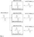
Fig. 1 schematically illustrates a processing flow of the filter bank. Here, a filter bank that applies three band-pass filters 1-3 to an input signal x(n) is considered. It is assumed that the filter bank is designed to match a specific input signal pattern to an impulse response of a specific band-pass filter. In an example ofFig. 1 , a waveform pattern of the input signal x(n) is substantially the same shape as an impulse response h2(n) of the band-pass filter 2, and it is expected that only an output signal y2(n) of the band-pass filter 2 takes a large output value in response to the waveform pattern of the input signal x(n) compared among the output of the band-pass filters 1-3. - Non-patent literature 1: M. Vetterli and C. Herley, "Wavelets and filter banks: theory and design," in IEEE Transactions on Signal Processing, vol. 40, no. 9, pp. 2207-2232, Sep 1992.
- In the filter bank analysis, because bands of respective band-pass filters overlap, features of a signal leak out to outputs of a plurality of adjacent filters, and analysis results may be redundant in some cases. In the example of
Fig. 1 , it is expected that only the output signal y2(n) of the band-pass filter 2 takes a large output value, but actually the waveform pattern of the input signal x(n) also leaks out to output signals y1(n) and y3(n) of the adjacent band-pass filters - An object of the present invention is to provide a signal feature extraction technique that can reduce leakage of an output signal to adjacent band-pass filters and in a time axis direction in filter bank analysis and flexibly cope with diversity of feature patterns of input signals to be analyzed.
- In order to solve the above-described problem, a signal feature extraction apparatus of a first aspect of the present invention is a signal feature extraction apparatus that extracts features of an input signal by filter bank analysis including a plurality of band-pass filters, assuming that M denotes a number of the band-pass filters, L denotes an integer which a maximum value of impulse response length of the band-pass filters is 2L+1, m denotes each integer from 1 or more to M or less, k denotes each integer from -2L or more to 2L or less, zk denotes a column vector having |k| zeros as elements, -x(n)=[x(n+L), ..., x(n+1), x(n), x(n-1), ..., x(n-L)]H denotes an input signal vector having an input signal sequence at time n as elements, and -hm=[hm(-L), ..., hm(-1), hm(0), hm(+1), ..., hm(L)]H denotes an impulse response vector having an impulse response sequence of an m-th band-pass filter as elements, the signal feature extraction apparatus including: an extended impulse response matrix generation part that generates an extended impulse response matrix He expressed by a following formula

using an impulse response sequence -hm,k which is, when k<0,

and when k≥0,

an expansion coefficient calculation part that obtains an expansion coefficient vector ^y(n) by calculating a following formula

using the input signal vector -x(n) and the extended impulse response matrix He; and a signal output part that outputs as an output signal at least one of expansion coefficients corresponding to a center impulse response vector -hm,0 of the extended impulse response matrix He of the expansion coefficient vector ^y(n). - A signal feature extraction apparatus of a second aspect of the present invention is a signal feature extraction apparatus that extracts features of an input signal by filter bank analysis including a plurality of band-pass filters, assuming that a superscript H denotes transposition, M denotes a number of the band-pass filters, L denotes a value which a maximum value of impulse response length of the band-pass filters is 2L+1, m denotes each integer from 1 or more to M or less, k denotes each integer from -2L or more to 2L or less, zk denotes a column vector having |k| zeros as elements, -x(n)=[x(n+L), ..., x(n+1), x(n), x(n-1), ..., x(n-L)]H denotes an impulse signal vector having an input signal sequence at time n as elements, and -hm=[hm(-L), ..., hm(-1), hm(0), hm(+1), ..., hm(L)]H denotes an input response vector having an impulse response sequence of an m-th band-pass filter as elements, the signal feature extraction apparatus including: an extended impulse response matrix generation part that generates an extended impulse response matrix Hc by extracting predetermined column vectors from an extended impulse response matrix He expressed by a following formula

generated by using an impulse response sequence -hm,k which is, when k<0,

and when k≥0,

an expansion coefficient calculation part that obtains an expansion coefficient vector ^y(n) by calculating a following formula

using the input signal vector -x(n) and the extended impulse response matrix Hc; and a signal output part that outputs as an output signal at least one of expansion coefficients corresponding to a center impulse response vector -hm,0 of the extended impulse response matrix Hc of the expansion coefficient vector ^y(n). - According to the signal feature extraction technique of the invention, it is possible to reduce leakage of an output signal between adjacent band-pass filters and in the time axis direction on filter bank analysis and flexibly cope with diversity of feature patterns of input signals to be analyzed.
-
-
Fig. 1 is a diagram for illustrating conventional filter bank processing; -
Fig. 2 is a diagram exemplifying a processing procedure of a signal feature extraction method of the prior art; -
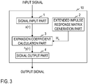
Fig. 3 is a diagram exemplifying a functional configuration of a signal feature extraction apparatus; -
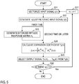
Fig. 4 is a diagram exemplifying a processing procedure of a signal feature extraction method of a first embodiment; and -
Fig. 5 is a diagram exemplifying a processing procedure of a signal feature extraction method of a second embodiment. - Symbols "∼", "^", "-", and the like used herein should be written directly above an immediately following character, but due to restriction of text notation, they are written immediately before the character. In formulas, the symbols are written at their original position, that is, directly above the character.
- A processing flow of a signal feature extraction method based on conventional filter bank analysis is shown in
Fig. 2 . The conventional filter bank analysis uses an input signal vector to be analyzed denoted as -x(n)=[x(n+L), ..., x(n+1), x(n), x(n-1), ..., x(n-L)]H having a signal sequence centering around a certain time n as elements and an impulse response vector -hm=[hm(-L), ..., hm(-1), hm(0), hm(+1), ..., hm(L)]H having an impulse response sequence of an m-th band-pass filter as elements to calculate an output signal ym(n) of the m-th band-pass filter by either multiply-add operation represented by a formula (1) or filter processing calculation equivalent to it.
- In the above formula, ·H (superscript H) denotes transpose of a vector or matrix, and when its elements are complex numbers, it denotes conjugate transpose. The maximum value of impulse response length of each band-pass filter is assumed to be 2L+1. Regarding m, it is any integer of 1 or more and M or less. Regarding M, it is the total number of the band-pass filters. There is a case where the impulse response length is different depending on the identification number m of band-pass filter, and some elements of an impulse response vector -hm related to a band-pass filter become 0 when impulse response length is less than 2L+1. In that case, multiply-add operation of the formula (1) of a part where an element is 0 can be omitted.
- One of reasons why leakage occurs in the output between adjacent band-pass filters in the above-described prior art is that pass bands of the adjacent band-pass filters are generally designed to overlap with each other. Considering a fact that an output signal is independently calculated for each band-pass filter in accordance with the formula (1) in the conventional filter bank is regarded as one of the reasons for leakage, a filter bank in the invention is configured in consideration of a mutual influence of band-pass filters.
- For example, in
Fig. 1 , it is considered representing the input signal vector -x(n) by a linear combination of impulse response vectors -h1, -h2, and -h3 of the respective filter banks. That is, it gives a relationship that satisfies a formula (2).
where,

- In the example of
Fig. 1 , because it considers a case where the input signal -x(n) has a waveform pattern of a shape equal to the impulse response -h2, that is -x(n)= -h2, expansion coefficients α1, α2, and α3 should be given like a formula (4).
- Such expansion coefficients are given as least-squares solutions of a formula (5) if 2L+1>3 is satisfied.

- Here, it is assumed that the expansion coefficients α1, α2, and α3 correspond to output signals at the time n, and it is considered that they are allocated like a formula (6).

- As a result, in the example of
Fig. 1 , a formula (7) is obtained, and leakage to the adjacent band-pass filters is prevented.
- On the other hand, outputs of the conventional band-pass filters are represented by a formula (8), which is different from the formula (6).

- In this case, even in the example of
Fig. 1 , results of the formula (7) are not obtained, and leakage to the adjacent band-pass filters occurs. - Because the input signal vector -x(n) is time series data varying over time, output signals obtained for an input signal vector -x(n+1) which is shifted by one sample become like a formula (9)

- Although the input signal vector -x(n+1) no longer coincides with any of the impulse response vectors -h1, -h2, and -h3 including the time axis, output signals y1(n+1), y2(n+1), and y3(n+1) take non-zero values. That is, leakage to the time axis direction cannot be prevented. Therefore, there is further considered an impulse response sequence -hm,k that is time shifted and becomes a formula (10) when k<0, and becomes a formula (11) when k≥0 for k=-2L, ..., -1, 0, 1, ..., 2L.


- In the above, zk denotes a column vector having |k| zeros as elements. It is assumed that these impulse response sequences are given as complex number sequences, sequences of real part and imaginary part can be mutually converted by Hilbert transformation or have an approximate equivalent relationship. It is considered extending the impulse response matrix H of the formula (3) to an extended impulse response matrix He of (2L+1)×M(4L+1) shown in a formula (12) and obtain an output signal from an expansion coefficient vector -y(n) satisfying a formula (13).


- However, in the formula (13), the number of elements of the expansion coefficient vector -y(n) which is an unknown number is M(4L+1), and because it exceeds the number (2L+1) of the equation, it becomes an indefinite problem of inferior determination. Therefore, it is impossible to uniquely obtain least-squares solutions in the same manner as the formula (6). Therefore, a solution by which a value of L1 norm ∥-y(n)∥1 is the minimum or a sufficiently small value among indefinite solutions is obtained by, for example, a lasso method and the following sparse solution ^y(n) is obtained.

- In the above, λ is a positive constant called a regularization parameter.
- What are actually used as output signals are only values ^y1(n), ..., ^ym(n), ..., ^yM(n) of expansion coefficients corresponding to center impulse response vectors -h1,0, ..., -hm,0, ..., -hM,0 which are not shifted, and further limited to only expansion coefficients corresponding to impulse responses having specific patterns of interest among the center impulse response vectors -h1,0, ..., -hm,0, ..., -hM,0. For example, if the input signal vector -x(n) coincides with any of the center impulse response vectors -h1,0, ..., -hm,0, ..., -hM,0 and the corresponding expansion coefficient takes a large value, the expansion coefficients for the input signal vector -x(n+1) which is shifted by one sample take a large value for the center impulse response vectors -h1,1, ..., -hm,1, ..., - hM,1 that are actually not output, but take a small value for the center impulse response vectors -h1,0, ..., -hm,0, ..., -hM,0 which are actually output, and therefore leakage to the time axis direction can be also prevented.
- Embodiments of the present invention will be described below in detail. Constituent parts having the same functions are given the same identification numbers in the drawings and redundant explanation will be omitted.
- A signal
feature extraction apparatus 10 of a first embodiment includes asignal input part 1, an extended impulse responsematrix generation part 2, an expansioncoefficient calculation part 3, and asignal output part 4 as shown inFig. 3 . The signalfeature extraction apparatus 10 performs processing of steps shown inFig. 4 and thereby implements a signal feature extraction method of the first embodiment. - The signal
feature extraction apparatus 10 is a special apparatus formed, for example, by causing a known or dedicated computer including a central processing unit (CPU), main storage device (RAM: Random Access Memory), and the like to read in a special program. The signalfeature extraction apparatus 10 performs the processing, for example, under control of the central processing unit. Data input into the signalfeature extraction apparatus 10 or data obtained by the processing is stored, for example, in the main storage device, and the data stored in the main storage device is read out on demand, and used for other processing. At least part of processing parts of the signalfeature extraction apparatus 10 may be configured by hardware such as an integrated circuit. - Processing procedure of the signal feature extraction method of the first embodiment will be described with reference to
Fig. 4 . - In step S11, the
signal input part 1 vectorizes an input signal x(n) to be analyzed and generates an input signal vector -x(n)=[x(n+L), ..., x(n+1), x(n), x(n-1), ..., x(n-L)]H. The generated input signal vector -x(n) is transmitted to the expansioncoefficient calculation part 3. - In step S12, the extended impulse response
matrix generation part 2 generates an impulse response vector -hm,k that is the formula (10) when k<0 and the formula (11) when k≥0 for m=1, ..., M; k=-2L, ..., -1, 0, 1, ..., 2L, and generates an extended impulse response matrix He of (2L+1)×M(4L+1) which is the formula (12). The generated extended impulse response matrix He is transmitted to the expansioncoefficient calculation part 3. Because the extended impulse response matrix He can be reused for each time n, it may be configured to execute only the first time as shown inFig. 4 . - In step S13, the expansion
coefficient calculation part 3 receives the input signal vector -x(n) from thesignal input part 1 and the extended impulse response matrix He from the extended impulse responsematrix generation part 2, and obtains an expansion coefficient vector ^y(n) by the formula (14). The obtained expansion coefficient vector ^y(n) is transmitted to thesignal output part 4. - In step S14, the
signal output part 4 receives the expansion coefficient vector ^y(n) from the expansioncoefficient calculation part 3 and outputs as an output signal at least one of expansion coefficients ^y1(n), ..., ^ym(n), ..., ^yM(n) corresponding to center impulse response vectors -h1,0, ..., -hm,0, ..., -hM,0 of the extended impulse response matrix He of the expansion coefficient vector ^y(n). - In step S15, it is determined whether there is an input signal x(n+1) at next time (n+1). If there is, 1 is added to a time index n in step S16, and the processing of steps S11 to S14 is performed again. If there is not, the processing is terminated.
- In the case where only output signals from specific band-pass filters are of interest and output signals of other band-pass filters are not used for analysis explicitly, instead of solving the optimization problem according to the formula (14) as it is, output signals may be generated by using an extended impulse response matrix Hc which is formed by mainly extracting column vectors of interest in the analysis from the extended impulse response matrix He. If the number of column vectors to be extracted is less than (2L+1), an expansion coefficient vector ^y(n) for the extended impulse response matrix Hc can be obtained as in a formula (15) by a least-squares method in the same manner as the formula (6).

- What are used as output signals are included in the extended impulse response matrix Hc among the elements of the expansion coefficient vector ^y(n), and in some cases, are only expansion coefficients that correspond to center impulse response vectors -h1,0, ..., -hm,0, ..., -hM,0 and are further limited as main objects of the analysis.
- There is a case where waveform patterns greatly different in shape from column vectors of the extended impulse response matrix Hc, such as noise, are mixed into the input signal -x(n) to be analyzed. In the case, after obtaining the expansion coefficient vector ^y(n) like a formula (16) for an input signal vector ∼x(n) obtained by applying filtering processing of removing components having a low correlation with the extended impulse response matrix Hc to the input signal vector -x(n), an output signal is obtained in the same manner as the first embodiment.

- Processing procedure of a signal feature extraction method of the second embodiment will be described with reference to
Fig. 5 . - In step S21, the
signal input part 1 vectorizes an input signal x(n) to be analyzed and generates an input signal vector -x(n) in the same manner as the first embodiment. In step S22, thesignal input part 1 may further apply filtering processing of removing components having a low correlation with the extended impulse response matrix Hc to the input signal vector -x(n) to generate an input signal vector ∼x(n). It is optional whether thesignal input part 1 performs step S22. The generated input signal vector -x(n) or ∼x(n) is transmitted to the expansioncoefficient calculation part 3. - In step S23, the extended impulse response
matrix generation part 2 generates an extended impulse response matrix He in the same manner as the first embodiment. Furthermore, it generates an extended impulse response matrix Hc by extracting column vectors of interest in analysis from the extended impulse response matrix He. The column vectors to be extracted are predetermined. The generated extended impulse response matrix Hc is transmitted to the expansioncoefficient calculation part 3. Because the extended impulse response matrix Hc can be reused for each time n, it may be configured to execute only the first time as shown inFig. 5 . - In step S24, the expansion
coefficient calculation part 3 receives the input signal vector -x(n) or ∼x(n) from thesignal input part 1 and the extended impulse response matrix Hc from the extended impulse responsematrix generation part 2, and obtains an expansion coefficient vector ^y(n) by the formula (15) when the input signal vector -x(n) is received and by the formula (16) when the input signal vector ∼x(n) is received. The obtained expansion coefficient vector ^y(n) is transmitted to thesignal output part 4. - In step S25, in the same manner as the first embodiment, the
signal output part 4 receives the expansion coefficient vector ^y(n) from the expansioncoefficient calculation part 3 and outputs as an output signal at least one of expansion coefficients corresponding to a center impulse response vector -hm,0 of the extended impulse response matrix Hc of the expansion coefficient vector ^y(n). - In step S26, it is determined whether there is an input signal x(n+1) at next time (n+1). If there is, 1 is added to a time index n in step S27, and then the processing of steps S21 to S25 is performed again. If there is not, the processing is terminated.
- A vector which is a complex conjugate of each column vector of the extended impulse response matrix He or Hc may be coupled with the extended impulse response matrix He or Hc, and then analyzed. Regarding a complex output signal, it may be alright to take a form in which the complex output signal is decomposed into a real part and an imaginary part, or an amplitude component and a phase component, and at least one of them is output. For example, in the cases where distortion is given to a phase characteristic caused by pre-processing such as a high-pass filter or low-pass filter and the waveform of a signal to be analyzed is deformed, or its characteristic pattern is deformed due to individual difference or symptom in an electrocardiogram waveform, an influence of the distortion and deformation can be extracted mainly as a difference in phase components. On the other hand, by observing amplitude components, it is possible to perform common feature extraction (for example, detection of QRS wave and T wave in the electrocardiogram waveform) which is not affected by individual events.
- Instead of calculating the formula (14) by using all the column vectors of the extended impulse response matrix He of (2L+1)×M(4L+1) indicated in the formula (12) in the first embodiment, some column vectors are omitted in a range not less than 2L+1, and a matrix of a smaller size may be used as an extended impulse response matrix.
- Furthermore, instead of the following inverse matrixes used in the formulas (15) and (16) in the second embodiment

it may be calculated by using

where δ is a positive actual number and I denotes a unit matrix. - With the above configuration, according to the signal feature extraction technique of the invention, leakage of output signals between band-pass filters or in the time axis direction in filter bank analysis is reduced, and therefore it is possible to obtain output signals in which the difference in features of each signal is more clearly shown, which is useful in signal classification and discrimination.
- Points of the invention are summarized as follows. In the signal feature extraction method based on the conventional filter bank analysis in which filtering processing is performed independently for each band-pass filter, signal leakage may occur because there is redundancy between band-pass filters and in the time axis direction. In order to prevent this, in the invention, a signal vector is represented by sparse expansion coefficients by over-complete base groups composed of impulse responses of band-pass filters. As a result, it is possible to obtain a result that only outputs of main band-pass filters having a specific feature take a large value and leakage to other band-pass filters is reduced. Obtaining these sparse expansion coefficients corresponds to eliminating mutual redundancy of each band-pass filter.
- Because the sparse expansion coefficients are generally high in calculation cost in many cases, in the case where an influence of noise components of no interest in analysis can be excluded beforehand, filtering processing of removing the noise components is applied to the signal to be analyzed to narrow a feature space of the signal, and the expansion coefficients can be obtained under fewer base groups. If the number of base groups can be made smaller than the number of samples of the signal vector to be analyzed, a simple calculation algorithm such as a least-squares method can be applied.
- Input signals to be analyzed in the invention are biological signals (for example, an electrocardiogram, a pulse wave, and a respiration curve) related to a physiological phenomenon having arbitrary periodicity including an acoustic signal or heartbeat, pulse, and breathing. The input signals to be analyzed repeat a local waveform pattern having substantially the same size and shape at almost periodic intervals. In addition, there are cases where a plurality of waveform patterns like QRS wave and T wave in the electrocardiogram waveform appear or noise is mixed and observed. The invention contributes to the extraction of features of these signals by outputting large values (peak values) in synchronization with the appearance of a waveform pattern of interest in such signals. In the invention, a measurement method of a biological signal is not questioned. Taking the heartbeat as an example, an object may be an electrocardiogram which is a method for measuring an electric activity associated with the heartbeat or it may be a seismocardiography (SCG) or ballistocardiography (BCG) which measures vibration of skin caused by the heartbeat with an accelerometer. Biological signals not described above may also be included in the analysis objects as long as they have the above characteristics.
- Although the embodiments of the present invention have been described above, specific configurations are not limited to these embodiments, and even if design changes and the like are appropriately made without departing from the spirit of the invention, it goes without saying that they are included in the invention. The various processes described in the embodiments may be executed not only in chronological order in accordance with the described order but also in parallel or individually in accordance with processing capability or necessity of an apparatus that executes the processes.
- When various processing functions of each apparatus described in the above embodiments are implemented by a computer, processing contents of the functions that each apparatus should have are described by a program. By executing the program by the computer, the various processing functions of each apparatus are implemented on the computer.
- The program describing the processing contents can be recorded on a computer-readable recording medium. The computer-readable recording medium may be any medium, for example, a magnetic recording device, an optical disc, a magneto-optical recording medium, and a semiconductor memory.
- Distribution of this program is carried out, for example, by selling, transferring, and renting a portable recording medium such as a DVD or CD-ROM in which the program is recorded. Furthermore, the program may be stored in a storage device of a server computer, and the program may be distributed by transferring the program from the server computer to another computer via a network.
- A computer that executes such a program, for example, stores the program recorded in the portable recording medium or the program transferred from the server computer in its own storage device. When processing is executed, the computer reads the program stored in its own recording medium and executes the processing according to the read program. Furthermore, as another mode of execution of the program, the computer may read the program directory from the portable recording medium and execute processing according to the program, or may sequentially execute, each time a program is transferred from the server computer to the computer, processing according to the received program. In addition, the above-described processing may be executed, not by transferring the program from the server computer to the computer, but by a configuration in which the above-described processing is executed by a so-called ASP (Application Service Provider) type service that achieves a processing function only by giving execution instructions and obtaining results. The program in this form includes information that is used for processing by an electronic computer and conforms to a program (data or the like that is not a direct instruction to a computer but has a characteristic defining processing of the computer).
- In this form, the apparatus is configured by executing a predetermined program on a computer, but at least part of the processing contents may be implemented by hardware.
Claims (7)
- A signal feature extraction apparatus for extracting features of an input signal by filter bank analysis including a plurality of band-pass filters,
assuming that M denotes a number of the band-pass filters, L denotes an integer which a maximum value of impulse response length of the band-pass filters is 2L+1, m denotes each integer from 1 or more to M or less, k denotes each integer from -2L or more to 2L or less, zk denotes a column vector having |k| zeros as elements, -x(n)=[x(n+L), ..., x(n+1), x(n), x(n-1), ..., x(n-L)]H denotes an input signal vector having an input signal sequence at time n as elements, and -hm=[hm(-L), ..., hm(-1), hm(0), hm(+1), ..., hm(L)]H denotes an impulse response vector having an impulse response sequence of an m-th band-pass filter as elements,
the signal feature extraction apparatus comprising:an extended impulse response matrix generation part that generates an extended impulse response matrix He expressed by a following formula when k<0,
 and when k≥0,
 an expansion coefficient calculation part that obtains an expansion coefficient vector ^y(n) by calculating a following formula
 a signal output part that outputs as an output signal at least one of expansion coefficients corresponding to a center impulse response vector -hm,0 of the extended impulse response matrix He of the expansion coefficient vector ^y(n).
 - A signal feature extraction apparatus for extracting features of an input signal by filter bank analysis including a plurality of band-pass filters,
assuming that a superscript H denotes transposition, M denotes a number of the band-pass filters, L denotes a value which a maximum value of impulse response length of the band-pass filters is 2L+1, m denotes each integer from 1 or more to M or less, k denotes each integer from -2L or more to 2L or less, zk denotes a column vector having |k| zeros as elements, -x(n)=[x(n+L), ..., x(n+1), x(n), x(n-1), ..., x(n-L)]H denotes an input signal vector having an input signal sequence at time n as elements, and -hm=[hm(-L), ..., hm(-1), hm(0), hm(+1), ..., hm(L)]H denotes an impulse response vector having an impulse response sequence of an m-th band-pass filter as elements,
the signal feature extraction apparatus comprising:an extended impulse response matrix generation part that generates an extended impulse response matrix Hc by extracting predetermined column vectors from an extended impulse response matrix He expressed by a following formula when k<0,
 and when k≥0,
 an expansion coefficient calculation part that obtains an expansion coefficient vector ^y(n) by calculating a following formula
 a signal output part that outputs as an output signal at least one of expansion coefficients corresponding to a center impulse response vector -hm,0 of the extended impulse response matrix Hc of the expansion coefficient vector ^y(n).
 - The signal feature extraction apparatus according to Claim 2, further comprising:a signal input part that generates an input signal vector ∼x(n) in which components having a low correlation with the extended impulse response matrix Hc are removed from the input signal vector -x(n), whereinthe expansion coefficient calculation part obtains the expansion coefficient vector ^y(n) by calculating a following formula

- A signal feature extraction method for extracting features of an input signal by filter bank analysis including a plurality of band-pass filters,
assuming that M denotes a number of the band-pass filters, L denotes an integer which a maximum value of impulse response length of the band-pass filters is 2L+1, m denotes each integer from 1 or more to M or less, k denotes each integer from -2L or more to 2L or less, zk denotes a column vector having |k| zeros as elements, -x(n)=[x(n+L), ..., x(n+1), x(n), x(n-1), ..., x(n-L)]H denotes an input signal vector having an input signal sequence at time n as elements, and -hm=[hm(-L), ..., hm(-1), hm(0), hm(+1), ..., hm(L)]H denotes an impulse response vector having an impulse response sequence of an m-th band-pass filter as elements,
the signal feature extraction method comprising:an extended impulse response matrix generation step in which an extended impulse response matrix generation part generates an extended impulse response matrix He expressed by a following formula when k<0,
 and when k≥0,
 an expansion coefficient calculation step in which an expansion coefficient calculation part obtains an expansion coefficient vector ^y(n) by calculating a following formula
 a signal output step in which a signal output part outputs as an output signal at least one of expansion coefficients corresponding to a center impulse response vector -hm,0 of the extended impulse response matrix He of the expansion coefficient vector ^y(n).
 - A signal feature extraction method for extracting features of an input signal by filter bank analysis including a plurality of band-pass filters,
assuming that a superscript H denotes transposition, M denotes a number of the band-pass filters, L denotes a value which a maximum value of impulse response length of the band-pass filters is 2L+1, m denotes each integer from 1 or more to M or less, k denotes each integer from -2L or more to 2L or less, zk denotes a column vector having |k| zeros as elements, - x(n)=[x(n+L), ..., x(n+1), x(n), x(n-1), ..., x(n-L)]H denotes an input signal vector having an input signal sequence at time n as elements, and -hm=[hm(-L), ..., hm(-1), hm(0), hm(+1), ..., hm(L)]H denotes an impulse response vector having an impulse response sequence of an m-th band-pass filter as elements,
the signal feature extraction method comprising:an extended impulse response matrix generation step in which an extended impulse response matrix generation part generates an extended impulse response matrix Hc by extracting predetermined column vectors from an extended impulse response matrix He expressed by a following formula when k<0,
 and when k≥0,
 an expansion coefficient calculation step in which an expansion coefficient calculation part obtains an expansion coefficient vector ^y(n) by calculating a following formula
 a signal output step in which a signal output part outputs as an output signal at least one of expansion coefficients corresponding to a center impulse response vector -hm,0 of the extended impulse response matrix Hc of the expansion coefficient vector ^y(n).
 - The signal feature extraction method according to Claim 5, further comprising
a signal input step in which a signal input part generates an input signal vector ∼x(n) in which components having a low correlation with the extended impulse response matrix Hc are removed from the input signal vector -x(n), wherein
the expansion coefficient calculation step obtains the expansion coefficient vector ^y(n) by calculating a following formula
- A program for causing a computer to function as the signal feature extraction apparatus according to any of Claims 1-3.
Applications Claiming Priority (2)
| Application Number | Priority Date | Filing Date | Title |
|---|---|---|---|
| JP2016236591 | 2016-12-06 | ||
| PCT/JP2017/043656 WO2018105614A1 (en) | 2016-12-06 | 2017-12-05 | Signal feature extraction device, signal feature extraction method, and program |
Publications (3)
| Publication Number | Publication Date |
|---|---|
| EP3553950A1 true EP3553950A1 (en) | 2019-10-16 |
| EP3553950A4 EP3553950A4 (en) | 2020-07-22 |
| EP3553950B1 EP3553950B1 (en) | 2023-10-11 |
Family
ID=62491061
Family Applications (1)
| Application Number | Title | Priority Date | Filing Date |
|---|---|---|---|
| EP17877712.4A Active EP3553950B1 (en) | 2016-12-06 | 2017-12-05 | Signal feature extraction device, signal feature extraction method, and program |
Country Status (6)
| Country | Link |
|---|---|
| US (1) | US10607631B2 (en) |
| EP (1) | EP3553950B1 (en) |
| JP (1) | JP6804554B2 (en) |
| AU (1) | AU2017373523B2 (en) |
| ES (1) | ES2964982T3 (en) |
| WO (1) | WO2018105614A1 (en) |
Family Cites Families (9)
| Publication number | Priority date | Publication date | Assignee | Title |
|---|---|---|---|---|
| JP3584458B2 (en) * | 1997-10-31 | 2004-11-04 | ソニー株式会社 | Pattern recognition device and pattern recognition method |
| US6308155B1 (en) * | 1999-01-20 | 2001-10-23 | International Computer Science Institute | Feature extraction for automatic speech recognition |
| JP4529492B2 (en) * | 2004-03-11 | 2010-08-25 | 株式会社デンソー | Speech extraction method, speech extraction device, speech recognition device, and program |
| JP2007054471A (en) * | 2005-08-26 | 2007-03-08 | Nippon Koden Corp | Pulse rate measuring device and pulse rate measuring method |
| JP5085700B2 (en) * | 2010-08-30 | 2012-11-28 | 株式会社東芝 | Speech synthesis apparatus, speech synthesis method and program |
| JP2013113866A (en) * | 2011-11-25 | 2013-06-10 | Nippon Telegr & Teleph Corp <Ntt> | Reverberation removal method, reverberation removal device and program |
| JP2015509443A (en) * | 2012-03-09 | 2015-03-30 | セノ メディカル インストルメンツ,インク. | Statistical mapping in photoacoustic imaging systems |
| US9837065B2 (en) * | 2014-12-08 | 2017-12-05 | Ford Global Technologies, Llc | Variable bandwidth delayless subband algorithm for broadband active noise control system |
| US10090005B2 (en) * | 2016-03-10 | 2018-10-02 | Aspinity, Inc. | Analog voice activity detection |
-
2017
- 2017-12-05 US US16/464,751 patent/US10607631B2/en active Active
- 2017-12-05 EP EP17877712.4A patent/EP3553950B1/en active Active
- 2017-12-05 ES ES17877712T patent/ES2964982T3/en active Active
- 2017-12-05 AU AU2017373523A patent/AU2017373523B2/en active Active
- 2017-12-05 JP JP2018555017A patent/JP6804554B2/en active Active
- 2017-12-05 WO PCT/JP2017/043656 patent/WO2018105614A1/en not_active Ceased
Also Published As
| Publication number | Publication date |
|---|---|
| WO2018105614A1 (en) | 2018-06-14 |
| EP3553950B1 (en) | 2023-10-11 |
| US10607631B2 (en) | 2020-03-31 |
| ES2964982T3 (en) | 2024-04-10 |
| AU2017373523A1 (en) | 2019-06-13 |
| JP6804554B2 (en) | 2020-12-23 |
| JPWO2018105614A1 (en) | 2019-10-24 |
| EP3553950A4 (en) | 2020-07-22 |
| AU2017373523B2 (en) | 2020-09-24 |
| US20190385631A1 (en) | 2019-12-19 |
Similar Documents
| Publication | Publication Date | Title |
|---|---|---|
| Novak et al. | Nonlinear system identification using exponential swept-sine signal | |
| Selesnick | Least squares with examples in signal processing | |
| US7099417B2 (en) | Trace video filtering using wavelet de-noising techniques | |
| de Oliveira et al. | Second order blind identification algorithm with exact model order estimation for harmonic and interharmonic decomposition with reduced complexity | |
| Khan et al. | Sparse reconstruction based on iterative TF domain filtering and Viterbi based IF estimation algorithm | |
| EP3553780A1 (en) | Signal feature extraction device, signal feature extraction method, and program | |
| Harris et al. | Subspace detectors: Efficient implementation | |
| Daube et al. | A whitening approach for transfer entropy permits the application to narrow-band signals | |
| Sourisseau et al. | Asymptotic analysis of synchrosqueezing transform—toward statistical inference with nonlinear-type time-frequency analysis | |
| Oh et al. | Signal reconstruction from nonuniformly spaced samples using evolutionary Slepian transform-based POCS | |
| Albright et al. | A comparison of the newly proposed Gabor order tracking technique vs. other order tracking methods | |
| EP3553950B1 (en) | Signal feature extraction device, signal feature extraction method, and program | |
| Ochab et al. | On the pros and cons of using temporal derivatives to assess brain functional connectivity | |
| JP2001312289A (en) | Filter circuit for band division and signal analyzer and signal processing device using the same | |
| Lu et al. | A second-order synchrosqueezing transform with a simple form of phase transformation | |
| Senay | Time‐frequency BSS of biosignals | |
| Tichavsky et al. | Corrections to “Performance Analysis of the FastICA Algorithm and CramÉr–Rao Bounds for Linear Independent Component Analysis” | |
| Alkishriwo et al. | Intrinsic mode chirp decomposition of non‐stationary signals | |
| Tiels et al. | Generation of initial estimates for Wiener-Hammerstein models via basis function expansions | |
| Reddy et al. | Sparse-Prony for spike detection in two-photon calcium imaging | |
| CN115441852A (en) | A Design Method of Time-Vertex Joint Critical Sampling Graph Filter Bank | |
| Allen et al. | Analysis and application of digital spectral warping in analog and mixed-signal testing | |
| Kodituwakku et al. | Radial function based kernel design for time-frequency distributions | |
| JP5439341B2 (en) | Superposition relaxation signal analysis apparatus, superposition relaxation signal analysis method, and superposition relaxation signal analysis program | |
| Wikner | Modelling an RF System and Evaluating Multi-Tone Signal Performance |
Legal Events
| Date | Code | Title | Description |
|---|---|---|---|
| STAA | Information on the status of an ep patent application or granted ep patent |
Free format text: STATUS: THE INTERNATIONAL PUBLICATION HAS BEEN MADE |
|
| PUAI | Public reference made under article 153(3) epc to a published international application that has entered the european phase |
Free format text: ORIGINAL CODE: 0009012 |
|
| STAA | Information on the status of an ep patent application or granted ep patent |
Free format text: STATUS: REQUEST FOR EXAMINATION WAS MADE |
|
| 17P | Request for examination filed |
Effective date: 20190708 |
|
| AK | Designated contracting states |
Kind code of ref document: A1 Designated state(s): AL AT BE BG CH CY CZ DE DK EE ES FI FR GB GR HR HU IE IS IT LI LT LU LV MC MK MT NL NO PL PT RO RS SE SI SK SM TR |
|
| AX | Request for extension of the european patent |
Extension state: BA ME |
|
| DAV | Request for validation of the european patent (deleted) | ||
| DAX | Request for extension of the european patent (deleted) | ||
| A4 | Supplementary search report drawn up and despatched |
Effective date: 20200619 |
|
| RIC1 | Information provided on ipc code assigned before grant |
Ipc: H03H 17/02 20060101AFI20200615BHEP Ipc: G06K 9/00 20060101ALI20200615BHEP Ipc: A61B 5/0452 20060101ALI20200615BHEP |
|
| GRAP | Despatch of communication of intention to grant a patent |
Free format text: ORIGINAL CODE: EPIDOSNIGR1 |
|
| STAA | Information on the status of an ep patent application or granted ep patent |
Free format text: STATUS: GRANT OF PATENT IS INTENDED |
|
| RIC1 | Information provided on ipc code assigned before grant |
Ipc: A61B 5/349 20210101ALI20230418BHEP Ipc: G06F 18/00 20230101ALI20230418BHEP Ipc: H03H 17/02 20060101AFI20230418BHEP |
|
| INTG | Intention to grant announced |
Effective date: 20230509 |
|
| GRAS | Grant fee paid |
Free format text: ORIGINAL CODE: EPIDOSNIGR3 |
|
| GRAA | (expected) grant |
Free format text: ORIGINAL CODE: 0009210 |
|
| STAA | Information on the status of an ep patent application or granted ep patent |
Free format text: STATUS: THE PATENT HAS BEEN GRANTED |
|
| AK | Designated contracting states |
Kind code of ref document: B1 Designated state(s): AL AT BE BG CH CY CZ DE DK EE ES FI FR GB GR HR HU IE IS IT LI LT LU LV MC MK MT NL NO PL PT RO RS SE SI SK SM TR |
|
| REG | Reference to a national code |
Ref country code: GB Ref legal event code: FG4D |
|
| REG | Reference to a national code |
Ref country code: CH Ref legal event code: EP |
|
| REG | Reference to a national code |
Ref country code: DE Ref legal event code: R096 Ref document number: 602017075321 Country of ref document: DE |
|
| REG | Reference to a national code |
Ref country code: IE Ref legal event code: FG4D |
|
| REG | Reference to a national code |
Ref country code: LT Ref legal event code: MG9D |
|
| REG | Reference to a national code |
Ref country code: NL Ref legal event code: MP Effective date: 20231011 |
|
| REG | Reference to a national code |
Ref country code: AT Ref legal event code: MK05 Ref document number: 1621243 Country of ref document: AT Kind code of ref document: T Effective date: 20231011 |
|
| PG25 | Lapsed in a contracting state [announced via postgrant information from national office to epo] |
Ref country code: NL Free format text: LAPSE BECAUSE OF FAILURE TO SUBMIT A TRANSLATION OF THE DESCRIPTION OR TO PAY THE FEE WITHIN THE PRESCRIBED TIME-LIMIT Effective date: 20231011 |
|
| PG25 | Lapsed in a contracting state [announced via postgrant information from national office to epo] |
Ref country code: GR Free format text: LAPSE BECAUSE OF FAILURE TO SUBMIT A TRANSLATION OF THE DESCRIPTION OR TO PAY THE FEE WITHIN THE PRESCRIBED TIME-LIMIT Effective date: 20240112 |
|
| PG25 | Lapsed in a contracting state [announced via postgrant information from national office to epo] |
Ref country code: IS Free format text: LAPSE BECAUSE OF FAILURE TO SUBMIT A TRANSLATION OF THE DESCRIPTION OR TO PAY THE FEE WITHIN THE PRESCRIBED TIME-LIMIT Effective date: 20240211 |
|
| REG | Reference to a national code |
Ref country code: ES Ref legal event code: FG2A Ref document number: 2964982 Country of ref document: ES Kind code of ref document: T3 Effective date: 20240410 |
|
| PG25 | Lapsed in a contracting state [announced via postgrant information from national office to epo] |
Ref country code: LT Free format text: LAPSE BECAUSE OF FAILURE TO SUBMIT A TRANSLATION OF THE DESCRIPTION OR TO PAY THE FEE WITHIN THE PRESCRIBED TIME-LIMIT Effective date: 20231011 |
|
| PG25 | Lapsed in a contracting state [announced via postgrant information from national office to epo] |
Ref country code: AT Free format text: LAPSE BECAUSE OF FAILURE TO SUBMIT A TRANSLATION OF THE DESCRIPTION OR TO PAY THE FEE WITHIN THE PRESCRIBED TIME-LIMIT Effective date: 20231011 |
|
| PG25 | Lapsed in a contracting state [announced via postgrant information from national office to epo] |
Ref country code: LT Free format text: LAPSE BECAUSE OF FAILURE TO SUBMIT A TRANSLATION OF THE DESCRIPTION OR TO PAY THE FEE WITHIN THE PRESCRIBED TIME-LIMIT Effective date: 20231011 Ref country code: IS Free format text: LAPSE BECAUSE OF FAILURE TO SUBMIT A TRANSLATION OF THE DESCRIPTION OR TO PAY THE FEE WITHIN THE PRESCRIBED TIME-LIMIT Effective date: 20240211 Ref country code: GR Free format text: LAPSE BECAUSE OF FAILURE TO SUBMIT A TRANSLATION OF THE DESCRIPTION OR TO PAY THE FEE WITHIN THE PRESCRIBED TIME-LIMIT Effective date: 20240112 Ref country code: BG Free format text: LAPSE BECAUSE OF FAILURE TO SUBMIT A TRANSLATION OF THE DESCRIPTION OR TO PAY THE FEE WITHIN THE PRESCRIBED TIME-LIMIT Effective date: 20240111 Ref country code: AT Free format text: LAPSE BECAUSE OF FAILURE TO SUBMIT A TRANSLATION OF THE DESCRIPTION OR TO PAY THE FEE WITHIN THE PRESCRIBED TIME-LIMIT Effective date: 20231011 Ref country code: PT Free format text: LAPSE BECAUSE OF FAILURE TO SUBMIT A TRANSLATION OF THE DESCRIPTION OR TO PAY THE FEE WITHIN THE PRESCRIBED TIME-LIMIT Effective date: 20240212 |
|
| PG25 | Lapsed in a contracting state [announced via postgrant information from national office to epo] |
Ref country code: SE Free format text: LAPSE BECAUSE OF FAILURE TO SUBMIT A TRANSLATION OF THE DESCRIPTION OR TO PAY THE FEE WITHIN THE PRESCRIBED TIME-LIMIT Effective date: 20231011 Ref country code: RS Free format text: LAPSE BECAUSE OF FAILURE TO SUBMIT A TRANSLATION OF THE DESCRIPTION OR TO PAY THE FEE WITHIN THE PRESCRIBED TIME-LIMIT Effective date: 20231011 Ref country code: PL Free format text: LAPSE BECAUSE OF FAILURE TO SUBMIT A TRANSLATION OF THE DESCRIPTION OR TO PAY THE FEE WITHIN THE PRESCRIBED TIME-LIMIT Effective date: 20231011 Ref country code: NO Free format text: LAPSE BECAUSE OF FAILURE TO SUBMIT A TRANSLATION OF THE DESCRIPTION OR TO PAY THE FEE WITHIN THE PRESCRIBED TIME-LIMIT Effective date: 20240111 Ref country code: LV Free format text: LAPSE BECAUSE OF FAILURE TO SUBMIT A TRANSLATION OF THE DESCRIPTION OR TO PAY THE FEE WITHIN THE PRESCRIBED TIME-LIMIT Effective date: 20231011 Ref country code: HR Free format text: LAPSE BECAUSE OF FAILURE TO SUBMIT A TRANSLATION OF THE DESCRIPTION OR TO PAY THE FEE WITHIN THE PRESCRIBED TIME-LIMIT Effective date: 20231011 |
|
| PG25 | Lapsed in a contracting state [announced via postgrant information from national office to epo] |
Ref country code: DK Free format text: LAPSE BECAUSE OF FAILURE TO SUBMIT A TRANSLATION OF THE DESCRIPTION OR TO PAY THE FEE WITHIN THE PRESCRIBED TIME-LIMIT Effective date: 20231011 |
|
| REG | Reference to a national code |
Ref country code: DE Ref legal event code: R097 Ref document number: 602017075321 Country of ref document: DE |
|
| PG25 | Lapsed in a contracting state [announced via postgrant information from national office to epo] |
Ref country code: CZ Free format text: LAPSE BECAUSE OF FAILURE TO SUBMIT A TRANSLATION OF THE DESCRIPTION OR TO PAY THE FEE WITHIN THE PRESCRIBED TIME-LIMIT Effective date: 20231011 |
|
| PG25 | Lapsed in a contracting state [announced via postgrant information from national office to epo] |
Ref country code: SK Free format text: LAPSE BECAUSE OF FAILURE TO SUBMIT A TRANSLATION OF THE DESCRIPTION OR TO PAY THE FEE WITHIN THE PRESCRIBED TIME-LIMIT Effective date: 20231011 |
|
| PG25 | Lapsed in a contracting state [announced via postgrant information from national office to epo] |
Ref country code: SM Free format text: LAPSE BECAUSE OF FAILURE TO SUBMIT A TRANSLATION OF THE DESCRIPTION OR TO PAY THE FEE WITHIN THE PRESCRIBED TIME-LIMIT Effective date: 20231011 Ref country code: SK Free format text: LAPSE BECAUSE OF FAILURE TO SUBMIT A TRANSLATION OF THE DESCRIPTION OR TO PAY THE FEE WITHIN THE PRESCRIBED TIME-LIMIT Effective date: 20231011 Ref country code: RO Free format text: LAPSE BECAUSE OF FAILURE TO SUBMIT A TRANSLATION OF THE DESCRIPTION OR TO PAY THE FEE WITHIN THE PRESCRIBED TIME-LIMIT Effective date: 20231011 Ref country code: EE Free format text: LAPSE BECAUSE OF FAILURE TO SUBMIT A TRANSLATION OF THE DESCRIPTION OR TO PAY THE FEE WITHIN THE PRESCRIBED TIME-LIMIT Effective date: 20231011 Ref country code: DK Free format text: LAPSE BECAUSE OF FAILURE TO SUBMIT A TRANSLATION OF THE DESCRIPTION OR TO PAY THE FEE WITHIN THE PRESCRIBED TIME-LIMIT Effective date: 20231011 Ref country code: CZ Free format text: LAPSE BECAUSE OF FAILURE TO SUBMIT A TRANSLATION OF THE DESCRIPTION OR TO PAY THE FEE WITHIN THE PRESCRIBED TIME-LIMIT Effective date: 20231011 |
|
| REG | Reference to a national code |
Ref country code: CH Ref legal event code: PL |
|
| PLBE | No opposition filed within time limit |
Free format text: ORIGINAL CODE: 0009261 |
|
| STAA | Information on the status of an ep patent application or granted ep patent |
Free format text: STATUS: NO OPPOSITION FILED WITHIN TIME LIMIT |
|
| PG25 | Lapsed in a contracting state [announced via postgrant information from national office to epo] |
Ref country code: LU Free format text: LAPSE BECAUSE OF NON-PAYMENT OF DUE FEES Effective date: 20231205 |
|
| PG25 | Lapsed in a contracting state [announced via postgrant information from national office to epo] |
Ref country code: MC Free format text: LAPSE BECAUSE OF FAILURE TO SUBMIT A TRANSLATION OF THE DESCRIPTION OR TO PAY THE FEE WITHIN THE PRESCRIBED TIME-LIMIT Effective date: 20231011 |
|
| REG | Reference to a national code |
Ref country code: BE Ref legal event code: MM Effective date: 20231231 |
|
| PG25 | Lapsed in a contracting state [announced via postgrant information from national office to epo] |
Ref country code: MC Free format text: LAPSE BECAUSE OF FAILURE TO SUBMIT A TRANSLATION OF THE DESCRIPTION OR TO PAY THE FEE WITHIN THE PRESCRIBED TIME-LIMIT Effective date: 20231011 Ref country code: LU Free format text: LAPSE BECAUSE OF NON-PAYMENT OF DUE FEES Effective date: 20231205 |
|
| 26N | No opposition filed |
Effective date: 20240712 |
|
| REG | Reference to a national code |
Ref country code: IE Ref legal event code: MM4A |
|
| PG25 | Lapsed in a contracting state [announced via postgrant information from national office to epo] |
Ref country code: IE Free format text: LAPSE BECAUSE OF NON-PAYMENT OF DUE FEES Effective date: 20231205 |
|
| PG25 | Lapsed in a contracting state [announced via postgrant information from national office to epo] |
Ref country code: BE Free format text: LAPSE BECAUSE OF NON-PAYMENT OF DUE FEES Effective date: 20231231 |
|
| PG25 | Lapsed in a contracting state [announced via postgrant information from national office to epo] |
Ref country code: CH Free format text: LAPSE BECAUSE OF NON-PAYMENT OF DUE FEES Effective date: 20231231 |
|
| PG25 | Lapsed in a contracting state [announced via postgrant information from national office to epo] |
Ref country code: SI Free format text: LAPSE BECAUSE OF FAILURE TO SUBMIT A TRANSLATION OF THE DESCRIPTION OR TO PAY THE FEE WITHIN THE PRESCRIBED TIME-LIMIT Effective date: 20231011 |
|
| PG25 | Lapsed in a contracting state [announced via postgrant information from national office to epo] |
Ref country code: SI Free format text: LAPSE BECAUSE OF FAILURE TO SUBMIT A TRANSLATION OF THE DESCRIPTION OR TO PAY THE FEE WITHIN THE PRESCRIBED TIME-LIMIT Effective date: 20231011 Ref country code: IE Free format text: LAPSE BECAUSE OF NON-PAYMENT OF DUE FEES Effective date: 20231205 Ref country code: CH Free format text: LAPSE BECAUSE OF NON-PAYMENT OF DUE FEES Effective date: 20231231 Ref country code: BE Free format text: LAPSE BECAUSE OF NON-PAYMENT OF DUE FEES Effective date: 20231231 |
|
| PG25 | Lapsed in a contracting state [announced via postgrant information from national office to epo] |
Ref country code: FI Free format text: LAPSE BECAUSE OF FAILURE TO SUBMIT A TRANSLATION OF THE DESCRIPTION OR TO PAY THE FEE WITHIN THE PRESCRIBED TIME-LIMIT Effective date: 20231011 |
|
| PG25 | Lapsed in a contracting state [announced via postgrant information from national office to epo] |
Ref country code: CY Free format text: LAPSE BECAUSE OF FAILURE TO SUBMIT A TRANSLATION OF THE DESCRIPTION OR TO PAY THE FEE WITHIN THE PRESCRIBED TIME-LIMIT; INVALID AB INITIO Effective date: 20171205 |
|
| PG25 | Lapsed in a contracting state [announced via postgrant information from national office to epo] |
Ref country code: HU Free format text: LAPSE BECAUSE OF FAILURE TO SUBMIT A TRANSLATION OF THE DESCRIPTION OR TO PAY THE FEE WITHIN THE PRESCRIBED TIME-LIMIT; INVALID AB INITIO Effective date: 20171205 |
|
| PG25 | Lapsed in a contracting state [announced via postgrant information from national office to epo] |
Ref country code: TR Free format text: LAPSE BECAUSE OF FAILURE TO SUBMIT A TRANSLATION OF THE DESCRIPTION OR TO PAY THE FEE WITHIN THE PRESCRIBED TIME-LIMIT Effective date: 20231011 |
|
| PGFP | Annual fee paid to national office [announced via postgrant information from national office to epo] |
Ref country code: DE Payment date: 20251211 Year of fee payment: 9 |
|
| PGFP | Annual fee paid to national office [announced via postgrant information from national office to epo] |
Ref country code: GB Payment date: 20251219 Year of fee payment: 9 |
|
| PGFP | Annual fee paid to national office [announced via postgrant information from national office to epo] |
Ref country code: IT Payment date: 20251223 Year of fee payment: 9 |
|
| PGFP | Annual fee paid to national office [announced via postgrant information from national office to epo] |
Ref country code: FR Payment date: 20251229 Year of fee payment: 9 |
|
| REG | Reference to a national code |
Ref country code: DE Ref legal event code: R081 Ref document number: 602017075321 Country of ref document: DE Owner name: NTT, INC., JP Free format text: FORMER OWNER: NIPPON TELEGRAPH AND TELEPHONE CORPORATION, TOKYO, JP Ref country code: DE Ref legal event code: R082 Ref document number: 602017075321 Country of ref document: DE Representative=s name: DENNEMEYER & ASSOCIATES RECHTSANWALTSGESELLSCH, DE |
|
| PGFP | Annual fee paid to national office [announced via postgrant information from national office to epo] |
Ref country code: ES Payment date: 20260130 Year of fee payment: 9 |