EP3553895B1 - Mating assistance device for electrical connectors - Google Patents
Mating assistance device for electrical connectors Download PDFInfo
- Publication number
- EP3553895B1 EP3553895B1 EP18305421.2A EP18305421A EP3553895B1 EP 3553895 B1 EP3553895 B1 EP 3553895B1 EP 18305421 A EP18305421 A EP 18305421A EP 3553895 B1 EP3553895 B1 EP 3553895B1
- Authority
- EP
- European Patent Office
- Prior art keywords
- housing
- electrical connectors
- assistance device
- connector
- mating assistance
- Prior art date
- Legal status (The legal status is an assumption and is not a legal conclusion. Google has not performed a legal analysis and makes no representation as to the accuracy of the status listed.)
- Active
Links
Images



Classifications
-
- H—ELECTRICITY
- H01—ELECTRIC ELEMENTS
- H01R—ELECTRICALLY-CONDUCTIVE CONNECTIONS; STRUCTURAL ASSOCIATIONS OF A PLURALITY OF MUTUALLY-INSULATED ELECTRICAL CONNECTING ELEMENTS; COUPLING DEVICES; CURRENT COLLECTORS
- H01R13/00—Details of coupling devices of the kinds covered by groups H01R12/70 or H01R24/00 - H01R33/00
- H01R13/62—Means for facilitating engagement or disengagement of coupling parts or for holding them in engagement
- H01R13/629—Additional means for facilitating engagement or disengagement of coupling parts, e.g. aligning or guiding means, levers, gas pressure electrical locking indicators, manufacturing tolerances
- H01R13/62905—Additional means for facilitating engagement or disengagement of coupling parts, e.g. aligning or guiding means, levers, gas pressure electrical locking indicators, manufacturing tolerances comprising a camming member
- H01R13/62911—U-shaped sliding element
-
- H—ELECTRICITY
- H01—ELECTRIC ELEMENTS
- H01R—ELECTRICALLY-CONDUCTIVE CONNECTIONS; STRUCTURAL ASSOCIATIONS OF A PLURALITY OF MUTUALLY-INSULATED ELECTRICAL CONNECTING ELEMENTS; COUPLING DEVICES; CURRENT COLLECTORS
- H01R13/00—Details of coupling devices of the kinds covered by groups H01R12/70 or H01R24/00 - H01R33/00
- H01R13/62—Means for facilitating engagement or disengagement of coupling parts or for holding them in engagement
- H01R13/629—Additional means for facilitating engagement or disengagement of coupling parts, e.g. aligning or guiding means, levers, gas pressure electrical locking indicators, manufacturing tolerances
- H01R13/633—Additional means for facilitating engagement or disengagement of coupling parts, e.g. aligning or guiding means, levers, gas pressure electrical locking indicators, manufacturing tolerances for disengagement only
- H01R13/6335—Additional means for facilitating engagement or disengagement of coupling parts, e.g. aligning or guiding means, levers, gas pressure electrical locking indicators, manufacturing tolerances for disengagement only comprising a handle
-
- H—ELECTRICITY
- H01—ELECTRIC ELEMENTS
- H01R—ELECTRICALLY-CONDUCTIVE CONNECTIONS; STRUCTURAL ASSOCIATIONS OF A PLURALITY OF MUTUALLY-INSULATED ELECTRICAL CONNECTING ELEMENTS; COUPLING DEVICES; CURRENT COLLECTORS
- H01R43/00—Apparatus or processes specially adapted for manufacturing, assembling, maintaining, or repairing of line connectors or current collectors or for joining electric conductors
- H01R43/26—Apparatus or processes specially adapted for manufacturing, assembling, maintaining, or repairing of line connectors or current collectors or for joining electric conductors for engaging or disengaging the two parts of a coupling device
-
- H—ELECTRICITY
- H01—ELECTRIC ELEMENTS
- H01R—ELECTRICALLY-CONDUCTIVE CONNECTIONS; STRUCTURAL ASSOCIATIONS OF A PLURALITY OF MUTUALLY-INSULATED ELECTRICAL CONNECTING ELEMENTS; COUPLING DEVICES; CURRENT COLLECTORS
- H01R13/00—Details of coupling devices of the kinds covered by groups H01R12/70 or H01R24/00 - H01R33/00
- H01R13/62—Means for facilitating engagement or disengagement of coupling parts or for holding them in engagement
- H01R13/629—Additional means for facilitating engagement or disengagement of coupling parts, e.g. aligning or guiding means, levers, gas pressure electrical locking indicators, manufacturing tolerances
- H01R13/631—Additional means for facilitating engagement or disengagement of coupling parts, e.g. aligning or guiding means, levers, gas pressure electrical locking indicators, manufacturing tolerances for engagement only
Definitions
- the present invention relates to a mating assistance device for electrical connectors and a method for connecting electrical connectors with such a mating assistance device.
- Electrical connector assemblies utilized for cabin applications in commercial aerospace and other applications often comprise separate connectors that mate together to form a secure physical and electrical connection.
- the electrical connector assemblies for aerospace application shall meet altitude immersion requirements.
- the mating assistance devices known in the art are usually made of several parts which are assembled by screwing, welding and/or bonding when the connection between the connectors is achieved. Consequently, the mating assistance devices as known in the art require the use of tools, e.g. a screwdriver for the assembly. Furthermore, notwithstanding that the mating assistance device provided with machined parts are known to be a costly solution, they are also not particularly adapted in term of lightness and weight reduction for cabin applications in commercial aerospace.
- the utility model JP H05 84061U discloses using a U-shaped frame member with a pushable wedge for coupling two connectors.
- mating assistance device for electrical connectors according to claim 1.
- the displacement of the connector pushing element between the unlocked position to the locked position allows to move the electrical connectors towards the inside of the housing.
- the sealing of the electrical connectors is facilitated and realized without the need of using external tools. Therefore, the assembly of the electrical connectors inside the mating assistance device is simplified and the assembly cost can be reduced.
- the mating assistance device can be further improved according to various advantageous embodiments.
- the trajectory of the at least one connector pushing element from the unlocked position to the locked position can be inclined with respect to the normal of the direction of insertion of the electrical connector into the housing.
- the trajectory of the at least one connector pushing element from the unlocked position to the locked position is inclined at an angle comprised between 5° and 15° with respect to the normal of the direction of insertion of the electrical connector into the housing.
- the inclined trajectory of the connector pushing element can exercise a force onto the electrical connector to move it further into the housing and to achieve the necessary sealing.
- the at least one locking device can have the form of a bracket, in particular, the form of a U-shaped bracket having a configuration conforming to the shape of the housing.
- the force can be applied on two sides of the electrical connector and in addition, the same shape of locking device can be used on the left and the right side of the housing when connecting two electrical connectors.
- the U-shaped bracket can have a central portion provided with an inner surface from which extends two arms in the same direction such that the direction of the arm's length is inclined with respect to a direction extending normally from the inner surface of the central portion.
- the central portion can be used by the user to push the bracket from the unlocked to the locked position.
- the housing is a one-piece housing, in particular made of a molded plastic or a polymer material, and has the shape of a hollow beam with two opened-ends for receiving a terminal of the electrical connector.
- the simple design of the housing and the lightweight material used provide a light device with no loose parts.
- the overall assembly costs can be reduced compared with a screw-together design in the art.
- the at least one connector pushing element of the locking devices can be provided with one or more protrusions, in particular two protrusions, protruding towards the inside of the housing when in the locked position.
- the protrusions of the connector pushing element allow guiding and forcing the electrical connector to further move inside the housing when the locking device is moved from the unlocked position to the locked position.
- the shape of the one or more protrusions of the locking devices can be complementary to latch means provided on an interface of the electrical connector. With the complementary shapes, an efficient transmission of the pushing force can be obtained.
- the mating assistance device can further be provided with two retentions means configured to hold the at least one locking device respectively in the unlocked position and in the locked position respectively relative to the housing. This feature allows preventing an involuntary locking or unlocking of the locking device, in particular during the transportation of the mating assistance device.
- the retention means can be configured to provide a form-fit connection between the housing and the at least one connector pushing element in the unlocked position and in the locked position.
- the retentions means can comprise two recesses or grooves on the at least one connector pushing element, in particular longitudinal grooves, configured to fit to a protruding element of the housing, the protrusion element protruding towards the at least one connector pushing element.
- the form-fit connection in the unlocked and locked position can be realized without any external tool, and only by means of the retentions means integral with the mating assistance device. This allows simplifying the assembly step while reducing the assembly cost.
- the locking devices and/or the housing can comprise at least one handle for pulling the locking device from the locked position to the unlocked position.
- the mating of the electrical connectors can be reversed, therefore allowing an easy versatile use in comparison with a soldered or a bonded assembly which have to be destroyed to disassemble the connection.
- the locking devices and/or the housing further can comprise at least one opening with an undercut configured for allowing an unmating of the electrical connectors, in particular by using an external tool.
- an external tool configured for allowing an unmating of the electrical connectors, in particular by using an external tool.
- a center region of the housing can be provided with flanges or a flange receiving region.
- the device can be easily mount to other parts.
- the object of the present invention is also achieved with a method for connecting electrical connectors according to claim 14.
- sealed electrical connections satisfying the high requirements of the aerospace industry, can be achieved without using external tools.
- FIG. 1 and Figure 2 represent a mating assistance device 1 according to the present invention.
- the mating assistance device 1 comprises a housing 3 and two locking devices 5, 7 movable with respect to the housing 3.
- the locking devices 5, 7 are illustrated in the unlocked position relative to the housing 3.
- the housing 3 is a one-piece housing, made of a molded plastic or a polymer material, and has the shape of a hollow beam with two opened-ends 9, 11 for receiving a terminal of an electrical connector (not represented in Figures 1 and 2 ) according to a direction of insertion of the electrical connectors inside the housing 3 and represented by the arrow A.
- a center region 4 of the housing 3 may be provided with flanges or a flange receiving region.
- the locking devices 5, 7 are identical and are mounted on the housing 3 with mirror symmetry with respect to the center region 4. In another embodiment, the locking devices 5, 7 may be different from each other.
- Each locking device 5, 7 has the form of a U-shaped bracket having a complementary shape to the housing 3, as it can be seen in Figure 2 .
- Each U-shaped locking device 5, 7 is provided with a central portion having an inner surface 12 from which extends two arms 14, 16 providing respectively two connector pushing elements 15, 17.
- the central portion 13 of each locking device 5, 7 can be used as a pushing-button by an operator for moving the locking devices 5, 7 from the unlocked to the locked position according to the locking direction represented by the arrow B.
- the locking direction B is perpendicular to the direction of insertion A.
- the direction N1 of the normal extending from the inner surface 12 of the central portion 13 of the locking device 5 and the locking direction B are parallel, as illustrated in Figure 2 .
- the direction L1 of the length l1 of the connector pushing element 15, 17 is inclined with respect to the locking direction B with the angle ⁇ . Therefore, the trajectory of each connector pushing element 15, 17 from the unlocked position to the locked position is inclined with respect to the locking direction B according to the angle ⁇ .
- the locking device 5 is mounted on the housing 3 such that when the locking device 5 moves from the unlocked to the locking position according to the locking direction B, the inclination of the connector pushing elements 15, 17 forming the angle ⁇ is oriented towards the center region 4 of the housing 3.
- the inclination of the connector pushing elements 15, 17 can provide the effect of moving and compressing each electrical connector towards the center region 4 of the housing 3 for sealing the electrical connectors together when inserted into the housing.
- the altitude immersion requirement can be satisfied.
- the connector pushing elements 15, 17 of each locking device 5, 7 are respectively provided with inner surfaces 19, 21 facing each other.
- the surfaces 19, 21 of the connector pushing elements 15, 17 are provided with two protrusions 23, 25 protruding towards the inside 27 of the housing 3 when the locking devices 5, 7 are mounted to the housing 3.
- the shapes of the first and second protrusions 23, 25 of the locking devices 5, 7 are complementary to an interface of an electrical connector. The interface of the electrical connector will be further in Figure 4b .
- the mating assistance device 1 is further provided with retentions means 28, 30, 32 configured to hold the locking device 5, 7 in the unlocked position and in the locked position respectively relative to the housing 3.
- the retentions means 28, 30 of each connector pushing element 15, 17 are longitudinal grooves 29, 31 provided on the surface 19, 21.
- the longitudinal groove 29, 31 are dimensioned to fit to a mating protruding element 33 of the retention means 32 of the housing 3, the protruding element 33 protruding towards the connector pushing element 15, 17.
- the retention means 28, 30, 32 are configured to provide a form-fit connection between the housing 3 and each of the connector pushing element 15, 17 in the unlocked position and in the locked position.
- the locking device 5, 7 In the unlocked position, as illustrated in Figure 1 , the locking device 5, 7 is hold by form-fit connection between the retention means 30, 31 and the retention means 32, 33 of the housing 3. In the locked position, the locking device 5, 7 is hold by form-fit connection between the retention means 28, 29 and the retention means 32, 33 of the housing 3.
- Each locking device 5, 7 and the housing 3 respectively comprise a handle 35, 37 for pulling the locking device 5, 7 from the locked position to the unlocked position.
- Each locking device 5, 7 and the housing 3 further respectively comprise an opening with an undercut 39, 41 configured to allow an unmating of the electrical connectors, in particular by using an external tool.
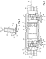
- Figure 4 illustrates a state wherein two electrical connectors 43, 45 have been partially introduced into the mating assistance device 1 and the locking device 5, 7 are in the unlocked position - as further illustrated in Figure 4a .
- the electrical connectors 43, 45 are inserted into the housing 3 of the mating assistance device 1 by the open-ends 9, 11 according to the direction of insertion A. At the step illustrated in Figure 4 , the electrical connectors 43, 45 are not yet in contact and are separated by air 10 inside the housing 3.
- the locking device 7 is hold in the unlocked position by form-fit connection between the retention means 30, 31 of the connection pushing element 15 and the retention means 32, 33 of the housing 3.
- each electrical connector 43, 45 is provided with latch means 47 on an interface 49.
- the latch means 47 comprises a ramp 51 and two protrusions 53, 55, here in the form of wedges 53, 55 adjacent each side of the ramp 51 perpendicular to the slope 51a of the ramp 51.
- the displacement of the electrical connectors 43, 45 in the insertion direction A has moved the latch means 47 such that the second protrusion 25 of the connection pushing element 15 slides over the surface of interface 49 and is guided to the ramp 51.
- the dimensions of the first and second protrusions 23, 25 are adapted with respect to the dimensions of the latch means 47 of the electrical connectors 43, 45.
- the second protrusion 25 is then positioned between the wedges 53, 55 of the latch means 47.
- the locking device 5, 7 can still not be moved into the locked position in the locking position B, as the first and second protrusions 23, 25 are blocked by the wedges 53, 55.
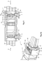
- the electrical connectors 43, 45 have been further inserted into the housing 3 according the direction of insertion A by pushing the locking devices into the direction B.
- the air gap 10 is further reduced in comparison to the one illustrated in Figure 5 .
- the second protrusion 25 of the connector pushing element 15 slides further and partially behind the wedges 53, 55 on the side of the open-end 9, 11 of the housing 3.
- the inclination of the direction L1 of the connector pushing element 15 with respect to the locking direction B allows a displacement of the connector pushing element 15 in the direction of insertion A when the locking device 5, 7 is moved from the unlocked to the locked position.
- the trajectory of the connector pushing element 15 from the unlocked position to the locked position is inclined with respect to the locking direction B, preferentially at an angle ⁇ comprised between 5° and 15°.
- the inclination of the connector pushing elements 15, 17 of each locking devices 5, 7 are oriented towards the center region 4 of the housing 3 with respect to the normal direction N1 and the locking direction B.
- the inclination of the connector pushing elements 15, 17 provides the effect of moving each electrical connector 43, 45 towards the center region 4 of the housing 3 by means of the protrusions 23, 25 so that they can be compressed together to achieve the desired sealing.
- the inclined trajectory of the protrusions 23, 25 with respect to the normal direction N1 and the locking direction B have the effect of compressing the electrical connectors 43, 45 inwards the housing 3.
- the latch means 47 of each electrical connectors 43, 45 are separated by a distance X.
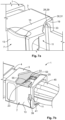
- the locking devices 5, 7 By pressing on the central portion 13 (see Figure 7a ) of the locking devices 5, 7 in the locking direction B, the locking devices 5, 7 can be moved into the housing 3 such that the electrical connectors 43, 45 are mated together. A little air 10 remains between the connectors 43 and 45. Only the elastomeric sealing cone devices from the male connector 45 are compressed into the front opposite cone recesses of the female connector 43.
- the mating assistance device 1 allowed the electrical connectors 43, 45 to be sealed according to the immersion at low air pressure requirement.
Landscapes
- Engineering & Computer Science (AREA)
- Manufacturing & Machinery (AREA)
- Details Of Connecting Devices For Male And Female Coupling (AREA)
Description
- The present invention relates to a mating assistance device for electrical connectors and a method for connecting electrical connectors with such a mating assistance device.
- Electrical connector assemblies utilized for cabin applications in commercial aerospace and other applications often comprise separate connectors that mate together to form a secure physical and electrical connection. In particular, the electrical connector assemblies for aerospace application shall meet altitude immersion requirements.
- To achieve an effective, properly aligned and sealed electrical connection of the connectors, it is common to employ a mating assistance device for connecting the electrical connectors together, as shown in
JP 2003/031305 A - The mating assistance devices known in the art are usually made of several parts which are assembled by screwing, welding and/or bonding when the connection between the connectors is achieved. Consequently, the mating assistance devices as known in the art require the use of tools, e.g. a screwdriver for the assembly. Furthermore, notwithstanding that the mating assistance device provided with machined parts are known to be a costly solution, they are also not particularly adapted in term of lightness and weight reduction for cabin applications in commercial aerospace.
- The utility model
JP H05 84061U - Therefore, it is an object of the present invention to provide a light, easy-to-use, tool-free and inexpensive mating assistance device for a connector assembly.
- The above-mentioned problem is addressed by mating assistance device for electrical connectors according to
claim 1. The displacement of the connector pushing element between the unlocked position to the locked position allows to move the electrical connectors towards the inside of the housing. As a result, thanks to the displacement of the connector pushing element in the direction of insertion of the electrical connector, the sealing of the electrical connectors is facilitated and realized without the need of using external tools. Therefore, the assembly of the electrical connectors inside the mating assistance device is simplified and the assembly cost can be reduced. - The mating assistance device can be further improved according to various advantageous embodiments.
- According to an embodiment, the trajectory of the at least one connector pushing element from the unlocked position to the locked position can be inclined with respect to the normal of the direction of insertion of the electrical connector into the housing. In particular, the trajectory of the at least one connector pushing element from the unlocked position to the locked position is inclined at an angle comprised between 5° and 15° with respect to the normal of the direction of insertion of the electrical connector into the housing. The inclined trajectory of the connector pushing element can exercise a force onto the electrical connector to move it further into the housing and to achieve the necessary sealing.
- According to another embodiment, the at least one locking device can have the form of a bracket, in particular, the form of a U-shaped bracket having a configuration conforming to the shape of the housing. When using a bracket, the force can be applied on two sides of the electrical connector and in addition, the same shape of locking device can be used on the left and the right side of the housing when connecting two electrical connectors.
- According to another embodiment, the U-shaped bracket can have a central portion provided with an inner surface from which extends two arms in the same direction such that the direction of the arm's length is inclined with respect to a direction extending normally from the inner surface of the central portion. The central portion can be used by the user to push the bracket from the unlocked to the locked position. By providing an inclined direction of the arms the desired movement of the connector pushing element can be obtained.
- According to the invention, the housing is a one-piece housing, in particular made of a molded plastic or a polymer material, and has the shape of a hollow beam with two opened-ends for receiving a terminal of the electrical connector. The simple design of the housing and the lightweight material used provide a light device with no loose parts. In addition, the overall assembly costs can be reduced compared with a screw-together design in the art.
- According to another embodiment, the at least one connector pushing element of the locking devices can be provided with one or more protrusions, in particular two protrusions, protruding towards the inside of the housing when in the locked position. The protrusions of the connector pushing element allow guiding and forcing the electrical connector to further move inside the housing when the locking device is moved from the unlocked position to the locked position.
- According to another embodiment, the shape of the one or more protrusions of the locking devices can be complementary to latch means provided on an interface of the electrical connector. With the complementary shapes, an efficient transmission of the pushing force can be obtained.
- According to another embodiment, the mating assistance device can further be provided with two retentions means configured to hold the at least one locking device respectively in the unlocked position and in the locked position respectively relative to the housing. This feature allows preventing an involuntary locking or unlocking of the locking device, in particular during the transportation of the mating assistance device.
- According to another embodiment, the retention means can be configured to provide a form-fit connection between the housing and the at least one connector pushing element in the unlocked position and in the locked position. In particular, the retentions means can comprise two recesses or grooves on the at least one connector pushing element, in particular longitudinal grooves, configured to fit to a protruding element of the housing, the protrusion element protruding towards the at least one connector pushing element. The form-fit connection in the unlocked and locked position can be realized without any external tool, and only by means of the retentions means integral with the mating assistance device. This allows simplifying the assembly step while reducing the assembly cost.
- According to another embodiment, the locking devices and/or the housing can comprise at least one handle for pulling the locking device from the locked position to the unlocked position. Hence, the mating of the electrical connectors can be reversed, therefore allowing an easy versatile use in comparison with a soldered or a bonded assembly which have to be destroyed to disassemble the connection.
- According to another embodiment, the locking devices and/or the housing further can comprise at least one opening with an undercut configured for allowing an unmating of the electrical connectors, in particular by using an external tool. In case a user's manual forces are not sufficient to move the locking device from the locked to the unlocked position, it still remains possible to decouple the connector again.
- According to another embodiment, a center region of the housing can be provided with flanges or a flange receiving region. Thus, the device can be easily mount to other parts.
- The object of the present invention is also achieved with a method for connecting electrical connectors according to
claim 14. With the inventive method sealed electrical connections satisfying the high requirements of the aerospace industry, can be achieved without using external tools. - Additional features and advantages will be described with reference to the drawings. In the description, reference is made to the accompanying figures that are meant to illustrate preferred embodiments of the invention. It is understood that such embodiments do not represent the full scope of the invention.
-
Figure 1 illustrates schematically a mating assistance device according to the invention; -
Figure 2 illustrates an exploded view of the mating assistance device according to the invention; -
Figure 3 illustrates a schematically top view of the locking device; -
Figure 4 . illustrates a cross-sectional and top view of the mating assistance device and two electrical connectors in the unlocked position; -
Figure 4a illustrates schematically a sectional view of the retentions means in the unlocked position; -
Figure 4b illustrates schematically an electrical connector to be inserted into the mating assistance device; -
Figure 5 . illustrates a sectional view of the mating assistance device in which the electrical connectors are inserted, and wherein the locking device is in the unlocked position; -
Figure 5a . illustrates a sectional view of the mating assistance device in the unlocked position; -
Figure 6 illustrates a sectional view of the mating assistance device and two electrical connectors, wherein the locking device are partially moved from the unlocked position to the locked position; -
Figure 7 . illustrates a cross-sectional and top view of the mating assistance device and two electrical connectors, wherein the locking device is in the locked position; -
Figure 7a . illustrates a sectional view of the mating assistance device in the locked position; -
Figure 7b . illustrates schematically a sectional view of the retentions means in the locked position. - The present invention will now be described with reference to the attached figures. Various structures, systems and devices are schematically depicted in the drawings for purposes of explanation only and so as to not obscure the present disclosure with details, which are well known to those skilled in the art. Nevertheless, the attached drawings are included to describe and explain illustrative examples of the present disclosure. The words and phrases used herein should be understood and interpreted to have a meaning consistent with the understanding of those words and phrases by those skilled in the relevant art. No special definition of a term or phrase, i.e., a definition that is different from the ordinary or customary meaning as understood by those skilled in the art, is intended to be implied by consistent usage of the term or phrase herein.
-
Figure 1 and Figure 2 represent amating assistance device 1 according to the present invention. Themating assistance device 1 comprises ahousing 3 and twolocking devices housing 3. Infigure 1 , thelocking devices housing 3. - The
housing 3 is a one-piece housing, made of a molded plastic or a polymer material, and has the shape of a hollow beam with two opened-ends Figures 1 and 2 ) according to a direction of insertion of the electrical connectors inside thehousing 3 and represented by the arrow A. - In another embodiment, not illustrated, a
center region 4 of thehousing 3 may be provided with flanges or a flange receiving region. - According to the first embodiment of the present invention, the
locking devices housing 3 with mirror symmetry with respect to thecenter region 4. In another embodiment, thelocking devices - Each
locking device housing 3, as it can be seen inFigure 2 . EachU-shaped locking device inner surface 12 from which extends twoarms connector pushing elements central portion 13 of each lockingdevice locking devices - As can be seen in
Figure 3 which illustrates a top view of thelocking device 5, the direction L1 of the length l1 of eacharm 14, 16 (accordingly of eachconnector pushing elements 15,17) is inclined with respect to a direction N1 extending normally from theinner surface 12 of thecentral portion 13. According to the first embodiment of the present invention, the inclination between the direction L1 and the direction N1 forms an angle α comprised between 5° and 15°. - The direction N1 of the normal extending from the
inner surface 12 of thecentral portion 13 of thelocking device 5 and the locking direction B are parallel, as illustrated inFigure 2 . - Accordingly, the direction L1 of the length l1 of the
connector pushing element connector pushing element - The
locking device 5 is mounted on thehousing 3 such that when thelocking device 5 moves from the unlocked to the locking position according to the locking direction B, the inclination of theconnector pushing elements center region 4 of thehousing 3. As a consequence, the inclination of theconnector pushing elements center region 4 of thehousing 3 for sealing the electrical connectors together when inserted into the housing. Thus, the altitude immersion requirement can be satisfied. The same applies for thesecond locking device 7. - Furthermore, the
connector pushing elements device inner surfaces 19, 21 facing each other. Thesurfaces 19, 21 of theconnector pushing elements protrusions housing 3 when thelocking devices housing 3. The shapes of the first andsecond protrusions locking devices Figure 4b . - The
mating assistance device 1 is further provided with retentions means 28, 30, 32 configured to hold thelocking device housing 3. The retentions means 28, 30 of eachconnector pushing element longitudinal grooves surface 19, 21. Thelongitudinal groove mating protruding element 33 of the retention means 32 of thehousing 3, the protrudingelement 33 protruding towards theconnector pushing element housing 3 and each of theconnector pushing element Figure 1 , thelocking device housing 3. In the locked position, thelocking device housing 3. - Each
locking device housing 3 respectively comprise ahandle locking device - Each
locking device housing 3 further respectively comprise an opening with an undercut 39, 41 configured to allow an unmating of the electrical connectors, in particular by using an external tool. - The successive steps of the method for connecting electrical connectors with the
mating assistance device 1 according to the prevent invention, are illustrated inFigure 4 - 7b . Elements with the same reference numeral already used inFigure 1, 2 and3 will not be described in detail again but reference is made to their description above. -
Figure 4 illustrates a state wherein twoelectrical connectors mating assistance device 1 and thelocking device Figure 4a . - The
electrical connectors housing 3 of themating assistance device 1 by the open-ends 9, 11 according to the direction of insertion A. At the step illustrated inFigure 4 , theelectrical connectors air 10 inside thehousing 3. - In the step of
Figure 4 and further illustrated inFigure 4a , thelocking device 7 is hold in the unlocked position by form-fit connection between the retention means 30, 31 of theconnection pushing element 15 and the retention means 32, 33 of thehousing 3. - As it can be seen in
Figure 4b , eachelectrical connector interface 49. The latch means 47 comprises aramp 51 and twoprotrusions wedges ramp 51 perpendicular to theslope 51a of theramp 51. - In
Figure 5 , theelectrical connectors housing 3 such that they are now in contact with each other. Consequently, theair volume 10 is reduced compared toFigure 4 . Thelocking devices - The displacement of the
electrical connectors second protrusion 25 of theconnection pushing element 15 slides over the surface ofinterface 49 and is guided to theramp 51. In particular, the dimensions of the first andsecond protrusions electrical connectors - At the step of
Figure 5 , and as it can be seen inFigure 5a , thesecond protrusion 25 is then positioned between thewedges locking device second protrusions wedges - At the step illustrated in
Figure 6 , theelectrical connectors housing 3 according the direction of insertion A by pushing the locking devices into the direction B. Theair gap 10 is further reduced in comparison to the one illustrated inFigure 5 . - The
second protrusion 25 of theconnector pushing element 15 slides further and partially behind thewedges end housing 3. - Thus, by applying a force in the locking direction B on the
central portion 13 of thelocking devices connectors - As mentioned, the inclination of the direction L1 of the
connector pushing element 15 with respect to the locking direction B allows a displacement of theconnector pushing element 15 in the direction of insertion A when thelocking device connector pushing element 15 from the unlocked position to the locked position is inclined with respect to the locking direction B, preferentially at an angle α comprised between 5° and 15°. The inclination of theconnector pushing elements locking devices center region 4 of thehousing 3 with respect to the normal direction N1 and the locking direction B. As a consequence, the inclination of theconnector pushing elements electrical connector center region 4 of thehousing 3 by means of theprotrusions protrusions electrical connectors housing 3. At the step illustrated inFigure 6 , the latch means 47 of eachelectrical connectors - In
Figure 7 , theelectrical connectors locking devices - By pressing on the central portion 13 (see
Figure 7a ) of thelocking devices locking devices housing 3 such that theelectrical connectors little air 10 remains between theconnectors male connector 45 are compressed into the front opposite cone recesses of thefemale connector 43. In comparison with the step illustrated inFigure 6 , it can be seen inFigure 7 that the latch means 47 of eachelectrical connectors electrical connectors 43, 45.In this situation, the first andsecond protrusions wedges interface 49. Thanks to the complementary shapes of thewedges protrusions connector pushing elements electrical connector protrusions - In this locked position of
Figure 7 and as it can be seen inFigure 7a , thelocking device 7 is hold in the locked position by form-fit connection between the retention means 28, 29 of theconnection pushing element 15 and the retention means 32, 33 of thehousing 3. - In the locked position illustrated in
Figure 7 , themating assistance device 1 allowed theelectrical connectors -
- 1 : mating assistance device
- 3 : housing
- 4 ; center region
- 5, 7 : locking device
- 10: air volume
- 9, 11 : opened end
- 12 : inner surface
- 13 : central portion
- 14: arm
- 15 : connector pushing element
- 16 : arm
- 17 : connector pushing element
- 19, 21 : inner surface
- 23, 25 : protrusion
- 27 : inside the housing
- 28 : retention means
- 29 : longitudinal groove
- 30 : retention means
- 31 : longitudinal groove
- 32: retention means
- 33 : protruding element
- 35, 37 : handle
- 39, 41 : opening with undercut
- 43, 45 : electrical connector
- 47 : latch means
- 49 : interface
- 51 : ramp
- 51a : slope
- 53, 55 : protrusion/wedge
- A : insertion direction
- B : locking direction
- l1 : length of the arm
- L1 : direction of the length of the arm
- N1 : direction normal to the inner surface of the central portion
- X : distance
- d : distance
- α : inclination angle
Claims (14)
- A mating assistance device for connecting electrical connectors together comprising:a housing (3) for receiving electrical connectors (43, 45), wherein the housing (3) is a one-piece housing, in particular made of a molded plastic or a polymer material, and has the shape of a hollow beam with two opened-ends (9, 11) for receiving a terminal of the electrical connectors (43, 45), andtwo locking devices (5, 7) movable between an unlocked and a locked position with respect to the housing (3), each locking device (5, 7) further comprising at least one connector pushing element (15, 17),wherein each locking device (5, 7), when moved from the unlocked to the locked position, is configured such that the at least one connector pushing element (15, 17) is displaceable in the direction of insertion (A) of an electrical connector (43, 45) into the housing (3).
- The mating assistance device for connecting electrical connectors together according to claim 1, wherein the trajectory (L1) of the at least one connector pushing element (15, 17) from the unlocked position to the locked position is inclined with respect to the normal (N1) of the direction of insertion (A) of the electrical connector (45, 47) into the housing (3).
- The mating assistance device for connecting electrical connectors together according to claim 2, wherein the trajectory (L1) of the at least one connector pushing element (15, 17) from the unlocked position to the locked position is inclined at an angle (α) comprised between 5° and 15° with respect to the normal (N1) of the direction of insertion (A) of the electrical connector (45, 47) into the housing (3).
- The mating assistance device for connecting electrical connectors according to one of the claims 1 to 3, wherein each locking device (5, 7) has the form of a bracket (5, 7), in particular, the form of a U-shaped bracket having a configuration conforming to the shape of the housing (3).
- The mating assistance device for connecting electrical connectors together according to claim 4, wherein the U-shaped bracket (5, 7) has a central portion (13) provided with an inner surface (12) from which extends two arms (14, 16) in the same direction (L1) such that the direction (L1) of the arm's length (l1) is inclined with respect to a direction (B) extending normally from the inner surface (12) of the central portion (13).
- The mating assistance device for connecting electrical connectors according to one of the claims 1 to 5, wherein the at least one connector pushing element (15, 17) of each locking device (5, 7) is provided with one or more protrusions (23, 25), in particular two protrusions (23, 25), protruding towards the inside (27) of the housing (3) when in the locked position.
- The mating assistance device for connecting electrical connectors together according to claim 6, wherein the shape of the one or more protrusions (23, 25) of each locking device (5, 7) is complementary to latch means (47) provided on an interface (49) of the electrical connector (43, 45).
- The mating assistance device for connecting electrical connectors together according to one of the claims 1 to 7, further provided with two retentions means (28, 30, 32) configured to hold each locking device (5, 7) respectively in the unlocked position and in the locked position respectively relative to the housing (3).
- The mating assistance device for connecting electrical connectors together according to claim 8, wherein the retention means (28, 30, 32) are configured to provide a form-fit connection between the housing (3) and the at least one connector pushing element (15, 17) in the unlocked position and in the locked position.
- The mating assistance device for connecting electrical connectors together according to claim 8 or 9, wherein the retentions means (28, 30, 32) comprises two recesses or grooves (28, 30) on the at least one connector pushing element (15, 17), in particular longitudinal grooves (29, 31), configured to fit to a protruding element (33) of the housing (3), the protrusion element (33) protruding towards the at least one connector pushing element (15, 17).
- The mating assistance device for connecting electrical connectors together according to one of the claim 1 to 10, wherein each locking device (5, 7) and/or the housing (3) comprise at least one handle (35, 37) for pulling the locking devices (5, 7) from the locked position to the unlocked position.
- The mating assistance device for connecting electrical connectors together according to one of the claims 1 to 11, wherein the each locking device (5, 7) and/or the housing (3) further comprise at least one opening with an undercut (39, 41) configured for allowing an unmating of the electrical connectors (43, 45), in particular by using an external tool.
- The mating assistance device for connecting electrical connectors together according to one of the claims 1 to 12, wherein a center region (4) of the housing (3) is provided with flanges or a flange receiving region.
- Method for connecting electrical connectors comprising an interface (49) provided with latch means (47), with the mating assistance device (1) according to claim 1 or 13, comprising the steps of:a) inserting a terminal of the electrical connectors (43, 45) into the housing (3) via the opened-ends (9, 11) of the mating assistance device (1) in the direction of insertion (A); andb) pushing the locking devices (5, 7) from the unlocked to the locked position to thereby push the latch means (47) of the electrical connectors (43, 45) further towards the center (4) of the housing (3) by the connector pushing elements (15, 17) following the inclined trajectories (L1).
Priority Applications (2)
| Application Number | Priority Date | Filing Date | Title |
|---|---|---|---|
| EP18305421.2A EP3553895B1 (en) | 2018-04-10 | 2018-04-10 | Mating assistance device for electrical connectors |
| US16/380,246 US10756486B2 (en) | 2018-04-10 | 2019-04-10 | Mating assistance device for electrical connectors |
Applications Claiming Priority (1)
| Application Number | Priority Date | Filing Date | Title |
|---|---|---|---|
| EP18305421.2A EP3553895B1 (en) | 2018-04-10 | 2018-04-10 | Mating assistance device for electrical connectors |
Publications (2)
| Publication Number | Publication Date |
|---|---|
| EP3553895A1 EP3553895A1 (en) | 2019-10-16 |
| EP3553895B1 true EP3553895B1 (en) | 2025-02-19 |
Family
ID=61972467
Family Applications (1)
| Application Number | Title | Priority Date | Filing Date |
|---|---|---|---|
| EP18305421.2A Active EP3553895B1 (en) | 2018-04-10 | 2018-04-10 | Mating assistance device for electrical connectors |
Country Status (2)
| Country | Link |
|---|---|
| US (1) | US10756486B2 (en) |
| EP (1) | EP3553895B1 (en) |
Families Citing this family (1)
| Publication number | Priority date | Publication date | Assignee | Title |
|---|---|---|---|---|
| EP3896800B1 (en) * | 2020-04-16 | 2025-12-03 | Connecteurs Electriques Deutsch | Electrical connector comprising a securing tab |
Citations (2)
| Publication number | Priority date | Publication date | Assignee | Title |
|---|---|---|---|---|
| DE3730020C1 (en) * | 1987-09-08 | 1988-09-29 | Kostal Leopold Gmbh & Co Kg | Electrical plug connector coupling |
| US20090286430A1 (en) * | 2008-05-14 | 2009-11-19 | Radiall | Multi-contact connector with a locking piece incorporated in the thickness of the housing |
Family Cites Families (12)
| Publication number | Priority date | Publication date | Assignee | Title |
|---|---|---|---|---|
| JPH0584061U (en) * | 1992-04-08 | 1993-11-12 | 古河電気工業株式会社 | Multi-pole connector |
| JP2784366B2 (en) * | 1993-04-12 | 1998-08-06 | 矢崎総業株式会社 | Low insertion force connector with drive lever |
| FR2705503B1 (en) * | 1993-05-21 | 1995-07-28 | Francelco Sa | Electrical connector with insertion and extraction drawer. |
| JPH07106033A (en) * | 1993-09-30 | 1995-04-21 | Sumitomo Wiring Syst Ltd | Standby connector |
| JP3316116B2 (en) * | 1995-09-19 | 2002-08-19 | タイコエレクトロニクスアンプ株式会社 | Electrical connector |
| JP3675242B2 (en) * | 1999-08-04 | 2005-07-27 | 矢崎総業株式会社 | Low insertion force connector |
| JP2003031305A (en) * | 2001-07-18 | 2003-01-31 | Yazaki Corp | Low insertion force connector |
| JP2003331983A (en) * | 2002-05-14 | 2003-11-21 | Sumitomo Wiring Syst Ltd | Lever connector |
| FR2864355A1 (en) * | 2003-12-19 | 2005-06-24 | Framatome Connectors Int | Connector case for motor vehicle, has clamp retaining electrical door-contact module in frame in locking position of module, and comprising rails that slide on shoulder of ribs, when module is in locking position |
| JP2014017135A (en) * | 2012-07-10 | 2014-01-30 | Tyco Electronics Japan Kk | Connector |
| US8936497B2 (en) * | 2013-02-26 | 2015-01-20 | International Business Machines Corporation | Connector with a rotatably coupled cam shaft having a connect-assist element |
| US9711515B1 (en) * | 2016-03-23 | 2017-07-18 | Kabushiki Kaisha Toshiba | Method of manufacturing semiconductor memory device |
-
2018
- 2018-04-10 EP EP18305421.2A patent/EP3553895B1/en active Active
-
2019
- 2019-04-10 US US16/380,246 patent/US10756486B2/en active Active
Patent Citations (2)
| Publication number | Priority date | Publication date | Assignee | Title |
|---|---|---|---|---|
| DE3730020C1 (en) * | 1987-09-08 | 1988-09-29 | Kostal Leopold Gmbh & Co Kg | Electrical plug connector coupling |
| US20090286430A1 (en) * | 2008-05-14 | 2009-11-19 | Radiall | Multi-contact connector with a locking piece incorporated in the thickness of the housing |
Also Published As
| Publication number | Publication date |
|---|---|
| US20190312386A1 (en) | 2019-10-10 |
| EP3553895A1 (en) | 2019-10-16 |
| US10756486B2 (en) | 2020-08-25 |
Similar Documents
| Publication | Publication Date | Title |
|---|---|---|
| EP1914847B1 (en) | Cable connector for vehicle door | |
| CN101809822B (en) | Connector with redundant terminal locking | |
| US9666972B2 (en) | Electrical connector | |
| CN203747155U (en) | Electrical plugging connector and electrical plugging connecting piece with electrical plugging connector | |
| JP4970571B2 (en) | Push-pull plug-in connector | |
| EP2724426A1 (en) | Connector assembly with chamber block and contact position assurance | |
| EP1872446B3 (en) | Grommet for electrical connector, and electrical connector comprising such a grommet | |
| KR101988187B1 (en) | Connector and connector assembly | |
| US6068522A (en) | Block connector | |
| US10985500B2 (en) | Connector assembly | |
| EP0716478B1 (en) | Electrical connection structure and method | |
| KR101515747B1 (en) | Lever mechanism for connector fitting, and connector | |
| US7841885B2 (en) | Electrical connector having improved releasable locking means | |
| EP3553895A1 (en) | Mating assistance device for electrical connectors | |
| US20200059039A1 (en) | Lever type connector | |
| US20250047037A1 (en) | Electrical connector assembly having floating mating interface | |
| US20250047027A1 (en) | Electrical connector assembly having floating mating interface | |
| US9647378B1 (en) | Electrical connector | |
| WO2019111094A1 (en) | Connector assembly with independent secondary lock with resilient positioning member | |
| US5429525A (en) | Connector assembly | |
| CN221997093U (en) | Magnetic eye-splice and braces | |
| CN110504590B (en) | A push-pull locking connector | |
| EP0971450B1 (en) | Secondary locked electrical connector | |
| US6315619B1 (en) | Three part electrical connector with preventation latching means | |
| US20220311174A1 (en) | Sealed electrical connector |
Legal Events
| Date | Code | Title | Description |
|---|---|---|---|
| PUAI | Public reference made under article 153(3) epc to a published international application that has entered the european phase |
Free format text: ORIGINAL CODE: 0009012 |
|
| STAA | Information on the status of an ep patent application or granted ep patent |
Free format text: STATUS: THE APPLICATION HAS BEEN PUBLISHED |
|
| AK | Designated contracting states |
Kind code of ref document: A1 Designated state(s): AL AT BE BG CH CY CZ DE DK EE ES FI FR GB GR HR HU IE IS IT LI LT LU LV MC MK MT NL NO PL PT RO RS SE SI SK SM TR |
|
| AX | Request for extension of the european patent |
Extension state: BA ME |
|
| STAA | Information on the status of an ep patent application or granted ep patent |
Free format text: STATUS: REQUEST FOR EXAMINATION WAS MADE |
|
| 17P | Request for examination filed |
Effective date: 20200325 |
|
| RBV | Designated contracting states (corrected) |
Designated state(s): AL AT BE BG CH CY CZ DE DK EE ES FI FR GB GR HR HU IE IS IT LI LT LU LV MC MK MT NL NO PL PT RO RS SE SI SK SM TR |
|
| STAA | Information on the status of an ep patent application or granted ep patent |
Free format text: STATUS: EXAMINATION IS IN PROGRESS |
|
| 17Q | First examination report despatched |
Effective date: 20210305 |
|
| REG | Reference to a national code |
Ref country code: DE Ref legal event code: R079 Free format text: PREVIOUS MAIN CLASS: H01R0013629000 Ipc: H01R0043260000 Ref country code: DE Ref legal event code: R079 Ref document number: 602018079282 Country of ref document: DE Free format text: PREVIOUS MAIN CLASS: H01R0013629000 Ipc: H01R0043260000 |
|
| GRAP | Despatch of communication of intention to grant a patent |
Free format text: ORIGINAL CODE: EPIDOSNIGR1 |
|
| STAA | Information on the status of an ep patent application or granted ep patent |
Free format text: STATUS: GRANT OF PATENT IS INTENDED |
|
| RIC1 | Information provided on ipc code assigned before grant |
Ipc: H01R 13/631 20060101ALN20231219BHEP Ipc: H01R 13/629 20060101ALI20231219BHEP Ipc: H01R 43/26 20060101AFI20231219BHEP |
|
| INTG | Intention to grant announced |
Effective date: 20240118 |
|
| GRAJ | Information related to disapproval of communication of intention to grant by the applicant or resumption of examination proceedings by the epo deleted |
Free format text: ORIGINAL CODE: EPIDOSDIGR1 |
|
| STAA | Information on the status of an ep patent application or granted ep patent |
Free format text: STATUS: EXAMINATION IS IN PROGRESS |
|
| INTC | Intention to grant announced (deleted) | ||
| GRAP | Despatch of communication of intention to grant a patent |
Free format text: ORIGINAL CODE: EPIDOSNIGR1 |
|
| STAA | Information on the status of an ep patent application or granted ep patent |
Free format text: STATUS: GRANT OF PATENT IS INTENDED |
|
| RIC1 | Information provided on ipc code assigned before grant |
Ipc: H01R 13/631 20060101ALN20240911BHEP Ipc: H01R 13/629 20060101ALI20240911BHEP Ipc: H01R 43/26 20060101AFI20240911BHEP |
|
| INTG | Intention to grant announced |
Effective date: 20240924 |
|
| RIC1 | Information provided on ipc code assigned before grant |
Ipc: H01R 13/631 20060101ALN20240913BHEP Ipc: H01R 13/629 20060101ALI20240913BHEP Ipc: H01R 43/26 20060101AFI20240913BHEP |
|
| GRAS | Grant fee paid |
Free format text: ORIGINAL CODE: EPIDOSNIGR3 |
|
| GRAA | (expected) grant |
Free format text: ORIGINAL CODE: 0009210 |
|
| STAA | Information on the status of an ep patent application or granted ep patent |
Free format text: STATUS: THE PATENT HAS BEEN GRANTED |
|
| AK | Designated contracting states |
Kind code of ref document: B1 Designated state(s): AL AT BE BG CH CY CZ DE DK EE ES FI FR GB GR HR HU IE IS IT LI LT LU LV MC MK MT NL NO PL PT RO RS SE SI SK SM TR |
|
| REG | Reference to a national code |
Ref country code: GB Ref legal event code: FG4D |
|
| REG | Reference to a national code |
Ref country code: CH Ref legal event code: EP |
|
| REG | Reference to a national code |
Ref country code: DE Ref legal event code: R096 Ref document number: 602018079282 Country of ref document: DE |
|
| REG | Reference to a national code |
Ref country code: IE Ref legal event code: FG4D |
|
| REG | Reference to a national code |
Ref country code: NL Ref legal event code: MP Effective date: 20250219 |
|
| PG25 | Lapsed in a contracting state [announced via postgrant information from national office to epo] |
Ref country code: RS Free format text: LAPSE BECAUSE OF FAILURE TO SUBMIT A TRANSLATION OF THE DESCRIPTION OR TO PAY THE FEE WITHIN THE PRESCRIBED TIME-LIMIT Effective date: 20250519 |
|
| PG25 | Lapsed in a contracting state [announced via postgrant information from national office to epo] |
Ref country code: FI Free format text: LAPSE BECAUSE OF FAILURE TO SUBMIT A TRANSLATION OF THE DESCRIPTION OR TO PAY THE FEE WITHIN THE PRESCRIBED TIME-LIMIT Effective date: 20250219 |
|
| PG25 | Lapsed in a contracting state [announced via postgrant information from national office to epo] |
Ref country code: PL Free format text: LAPSE BECAUSE OF FAILURE TO SUBMIT A TRANSLATION OF THE DESCRIPTION OR TO PAY THE FEE WITHIN THE PRESCRIBED TIME-LIMIT Effective date: 20250219 |
|
| PGFP | Annual fee paid to national office [announced via postgrant information from national office to epo] |
Ref country code: DE Payment date: 20250305 Year of fee payment: 8 |
|
| PG25 | Lapsed in a contracting state [announced via postgrant information from national office to epo] |
Ref country code: ES Free format text: LAPSE BECAUSE OF FAILURE TO SUBMIT A TRANSLATION OF THE DESCRIPTION OR TO PAY THE FEE WITHIN THE PRESCRIBED TIME-LIMIT Effective date: 20250219 |
|
| REG | Reference to a national code |
Ref country code: LT Ref legal event code: MG9D |
|
| PG25 | Lapsed in a contracting state [announced via postgrant information from national office to epo] |
Ref country code: IS Free format text: LAPSE BECAUSE OF FAILURE TO SUBMIT A TRANSLATION OF THE DESCRIPTION OR TO PAY THE FEE WITHIN THE PRESCRIBED TIME-LIMIT Effective date: 20250619 Ref country code: NO Free format text: LAPSE BECAUSE OF FAILURE TO SUBMIT A TRANSLATION OF THE DESCRIPTION OR TO PAY THE FEE WITHIN THE PRESCRIBED TIME-LIMIT Effective date: 20250519 |
|
| PG25 | Lapsed in a contracting state [announced via postgrant information from national office to epo] |
Ref country code: NL Free format text: LAPSE BECAUSE OF FAILURE TO SUBMIT A TRANSLATION OF THE DESCRIPTION OR TO PAY THE FEE WITHIN THE PRESCRIBED TIME-LIMIT Effective date: 20250219 |
|
| PG25 | Lapsed in a contracting state [announced via postgrant information from national office to epo] |
Ref country code: HR Free format text: LAPSE BECAUSE OF FAILURE TO SUBMIT A TRANSLATION OF THE DESCRIPTION OR TO PAY THE FEE WITHIN THE PRESCRIBED TIME-LIMIT Effective date: 20250219 |
|
| PG25 | Lapsed in a contracting state [announced via postgrant information from national office to epo] |
Ref country code: LV Free format text: LAPSE BECAUSE OF FAILURE TO SUBMIT A TRANSLATION OF THE DESCRIPTION OR TO PAY THE FEE WITHIN THE PRESCRIBED TIME-LIMIT Effective date: 20250219 Ref country code: PT Free format text: LAPSE BECAUSE OF FAILURE TO SUBMIT A TRANSLATION OF THE DESCRIPTION OR TO PAY THE FEE WITHIN THE PRESCRIBED TIME-LIMIT Effective date: 20250620 |
|
| PG25 | Lapsed in a contracting state [announced via postgrant information from national office to epo] |
Ref country code: GR Free format text: LAPSE BECAUSE OF FAILURE TO SUBMIT A TRANSLATION OF THE DESCRIPTION OR TO PAY THE FEE WITHIN THE PRESCRIBED TIME-LIMIT Effective date: 20250520 Ref country code: BG Free format text: LAPSE BECAUSE OF FAILURE TO SUBMIT A TRANSLATION OF THE DESCRIPTION OR TO PAY THE FEE WITHIN THE PRESCRIBED TIME-LIMIT Effective date: 20250219 |
|
| REG | Reference to a national code |
Ref country code: AT Ref legal event code: MK05 Ref document number: 1769268 Country of ref document: AT Kind code of ref document: T Effective date: 20250219 |
|
| PG25 | Lapsed in a contracting state [announced via postgrant information from national office to epo] |
Ref country code: SE Free format text: LAPSE BECAUSE OF FAILURE TO SUBMIT A TRANSLATION OF THE DESCRIPTION OR TO PAY THE FEE WITHIN THE PRESCRIBED TIME-LIMIT Effective date: 20250219 |
|
| PG25 | Lapsed in a contracting state [announced via postgrant information from national office to epo] |
Ref country code: SM Free format text: LAPSE BECAUSE OF FAILURE TO SUBMIT A TRANSLATION OF THE DESCRIPTION OR TO PAY THE FEE WITHIN THE PRESCRIBED TIME-LIMIT Effective date: 20250219 |
|
| PG25 | Lapsed in a contracting state [announced via postgrant information from national office to epo] |
Ref country code: DK Free format text: LAPSE BECAUSE OF FAILURE TO SUBMIT A TRANSLATION OF THE DESCRIPTION OR TO PAY THE FEE WITHIN THE PRESCRIBED TIME-LIMIT Effective date: 20250219 |
|
| PG25 | Lapsed in a contracting state [announced via postgrant information from national office to epo] |
Ref country code: IT Free format text: LAPSE BECAUSE OF FAILURE TO SUBMIT A TRANSLATION OF THE DESCRIPTION OR TO PAY THE FEE WITHIN THE PRESCRIBED TIME-LIMIT Effective date: 20250219 |
|
| PG25 | Lapsed in a contracting state [announced via postgrant information from national office to epo] |
Ref country code: AT Free format text: LAPSE BECAUSE OF FAILURE TO SUBMIT A TRANSLATION OF THE DESCRIPTION OR TO PAY THE FEE WITHIN THE PRESCRIBED TIME-LIMIT Effective date: 20250219 |
|
| PG25 | Lapsed in a contracting state [announced via postgrant information from national office to epo] |
Ref country code: EE Free format text: LAPSE BECAUSE OF FAILURE TO SUBMIT A TRANSLATION OF THE DESCRIPTION OR TO PAY THE FEE WITHIN THE PRESCRIBED TIME-LIMIT Effective date: 20250219 Ref country code: CZ Free format text: LAPSE BECAUSE OF FAILURE TO SUBMIT A TRANSLATION OF THE DESCRIPTION OR TO PAY THE FEE WITHIN THE PRESCRIBED TIME-LIMIT Effective date: 20250219 |
|
| PG25 | Lapsed in a contracting state [announced via postgrant information from national office to epo] |
Ref country code: RO Free format text: LAPSE BECAUSE OF FAILURE TO SUBMIT A TRANSLATION OF THE DESCRIPTION OR TO PAY THE FEE WITHIN THE PRESCRIBED TIME-LIMIT Effective date: 20250219 |
|
| PG25 | Lapsed in a contracting state [announced via postgrant information from national office to epo] |
Ref country code: SK Free format text: LAPSE BECAUSE OF FAILURE TO SUBMIT A TRANSLATION OF THE DESCRIPTION OR TO PAY THE FEE WITHIN THE PRESCRIBED TIME-LIMIT Effective date: 20250219 |
|
| REG | Reference to a national code |
Ref country code: DE Ref legal event code: R097 Ref document number: 602018079282 Country of ref document: DE |
|
| REG | Reference to a national code |
Ref country code: CH Ref legal event code: H13 Free format text: ST27 STATUS EVENT CODE: U-0-0-H10-H13 (AS PROVIDED BY THE NATIONAL OFFICE) Effective date: 20251125 |
|
| PG25 | Lapsed in a contracting state [announced via postgrant information from national office to epo] |
Ref country code: LU Free format text: LAPSE BECAUSE OF NON-PAYMENT OF DUE FEES Effective date: 20250410 |
|
| PG25 | Lapsed in a contracting state [announced via postgrant information from national office to epo] |
Ref country code: MC Free format text: LAPSE BECAUSE OF FAILURE TO SUBMIT A TRANSLATION OF THE DESCRIPTION OR TO PAY THE FEE WITHIN THE PRESCRIBED TIME-LIMIT Effective date: 20250219 |
|
| PLBE | No opposition filed within time limit |
Free format text: ORIGINAL CODE: 0009261 |
|
| STAA | Information on the status of an ep patent application or granted ep patent |
Free format text: STATUS: NO OPPOSITION FILED WITHIN TIME LIMIT |
|
| REG | Reference to a national code |
Ref country code: BE Ref legal event code: MM Effective date: 20250430 |
|
| PG25 | Lapsed in a contracting state [announced via postgrant information from national office to epo] |
Ref country code: BE Free format text: LAPSE BECAUSE OF NON-PAYMENT OF DUE FEES Effective date: 20250430 |
|
| PG25 | Lapsed in a contracting state [announced via postgrant information from national office to epo] |
Ref country code: CH Free format text: LAPSE BECAUSE OF NON-PAYMENT OF DUE FEES Effective date: 20250430 |
|
| 26N | No opposition filed |
Effective date: 20251120 |
|
| PGFP | Annual fee paid to national office [announced via postgrant information from national office to epo] |
Ref country code: GB Payment date: 20260313 Year of fee payment: 9 |
|
| PG25 | Lapsed in a contracting state [announced via postgrant information from national office to epo] |
Ref country code: IE Free format text: LAPSE BECAUSE OF NON-PAYMENT OF DUE FEES Effective date: 20250410 |
|
| PGFP | Annual fee paid to national office [announced via postgrant information from national office to epo] |
Ref country code: FR Payment date: 20260309 Year of fee payment: 9 |