EP3553298B1 - Vehicle generator control method and system thereof - Google Patents
Vehicle generator control method and system thereof Download PDFInfo
- Publication number
- EP3553298B1 EP3553298B1 EP17921270.9A EP17921270A EP3553298B1 EP 3553298 B1 EP3553298 B1 EP 3553298B1 EP 17921270 A EP17921270 A EP 17921270A EP 3553298 B1 EP3553298 B1 EP 3553298B1
- Authority
- EP
- European Patent Office
- Prior art keywords
- generator
- control relay
- contact
- generator control
- coil
- Prior art date
- Legal status (The legal status is an assumption and is not a legal conclusion. Google has not performed a legal analysis and makes no representation as to the accuracy of the status listed.)
- Active
Links
Images

Classifications
-
- F—MECHANICAL ENGINEERING; LIGHTING; HEATING; WEAPONS; BLASTING
- F02—COMBUSTION ENGINES; HOT-GAS OR COMBUSTION-PRODUCT ENGINE PLANTS
- F02D—CONTROLLING COMBUSTION ENGINES
- F02D41/00—Electrical control of supply of combustible mixture or its constituents
- F02D41/02—Circuit arrangements for generating control signals
- F02D41/04—Introducing corrections for particular operating conditions
- F02D41/06—Introducing corrections for particular operating conditions for engine starting or warming up
- F02D41/062—Introducing corrections for particular operating conditions for engine starting or warming up for starting
- F02D41/064—Introducing corrections for particular operating conditions for engine starting or warming up for starting at cold start
-
- F—MECHANICAL ENGINEERING; LIGHTING; HEATING; WEAPONS; BLASTING
- F02—COMBUSTION ENGINES; HOT-GAS OR COMBUSTION-PRODUCT ENGINE PLANTS
- F02D—CONTROLLING COMBUSTION ENGINES
- F02D29/00—Controlling engines, such controlling being peculiar to the devices driven thereby, the devices being other than parts or accessories essential to engine operation, e.g. controlling of engines by signals external thereto
- F02D29/06—Controlling engines, such controlling being peculiar to the devices driven thereby, the devices being other than parts or accessories essential to engine operation, e.g. controlling of engines by signals external thereto peculiar to engines driving electric generators
-
- F—MECHANICAL ENGINEERING; LIGHTING; HEATING; WEAPONS; BLASTING
- F02—COMBUSTION ENGINES; HOT-GAS OR COMBUSTION-PRODUCT ENGINE PLANTS
- F02D—CONTROLLING COMBUSTION ENGINES
- F02D41/00—Electrical control of supply of combustible mixture or its constituents
- F02D41/02—Circuit arrangements for generating control signals
- F02D41/04—Introducing corrections for particular operating conditions
- F02D41/042—Introducing corrections for particular operating conditions for stopping the engine
-
- F—MECHANICAL ENGINEERING; LIGHTING; HEATING; WEAPONS; BLASTING
- F02—COMBUSTION ENGINES; HOT-GAS OR COMBUSTION-PRODUCT ENGINE PLANTS
- F02N—STARTING OF COMBUSTION ENGINES; STARTING AIDS FOR SUCH ENGINES, NOT OTHERWISE PROVIDED FOR
- F02N11/00—Starting of engines by means of electric motors
- F02N11/04—Starting of engines by means of electric motors the motors being associated with current generators
-
- F—MECHANICAL ENGINEERING; LIGHTING; HEATING; WEAPONS; BLASTING
- F02—COMBUSTION ENGINES; HOT-GAS OR COMBUSTION-PRODUCT ENGINE PLANTS
- F02N—STARTING OF COMBUSTION ENGINES; STARTING AIDS FOR SUCH ENGINES, NOT OTHERWISE PROVIDED FOR
- F02N11/00—Starting of engines by means of electric motors
- F02N11/08—Circuits specially adapted for starting of engines
- F02N11/0814—Circuits specially adapted for starting of engines comprising means for controlling automatic idle-start-stop
- F02N11/0818—Conditions for starting or stopping the engine or for deactivating the idle-start-stop mode
- F02N11/0833—Vehicle conditions
- F02N11/084—State of vehicle accessories, e.g. air condition or power steering
-
- F—MECHANICAL ENGINEERING; LIGHTING; HEATING; WEAPONS; BLASTING
- F02—COMBUSTION ENGINES; HOT-GAS OR COMBUSTION-PRODUCT ENGINE PLANTS
- F02N—STARTING OF COMBUSTION ENGINES; STARTING AIDS FOR SUCH ENGINES, NOT OTHERWISE PROVIDED FOR
- F02N11/00—Starting of engines by means of electric motors
- F02N11/08—Circuits specially adapted for starting of engines
- F02N11/0862—Circuits specially adapted for starting of engines characterised by the electrical power supply means, e.g. battery
-
- F—MECHANICAL ENGINEERING; LIGHTING; HEATING; WEAPONS; BLASTING
- F02—COMBUSTION ENGINES; HOT-GAS OR COMBUSTION-PRODUCT ENGINE PLANTS
- F02N—STARTING OF COMBUSTION ENGINES; STARTING AIDS FOR SUCH ENGINES, NOT OTHERWISE PROVIDED FOR
- F02N11/00—Starting of engines by means of electric motors
- F02N11/08—Circuits specially adapted for starting of engines
- F02N11/087—Details of the switching means in starting circuits, e.g. relays or electronic switches
-
- F—MECHANICAL ENGINEERING; LIGHTING; HEATING; WEAPONS; BLASTING
- F02—COMBUSTION ENGINES; HOT-GAS OR COMBUSTION-PRODUCT ENGINE PLANTS
- F02N—STARTING OF COMBUSTION ENGINES; STARTING AIDS FOR SUCH ENGINES, NOT OTHERWISE PROVIDED FOR
- F02N19/00—Starting aids for combustion engines, not otherwise provided for
- F02N19/001—Arrangements thereof
-
- B—PERFORMING OPERATIONS; TRANSPORTING
- B60—VEHICLES IN GENERAL
- B60R—VEHICLES, VEHICLE FITTINGS, OR VEHICLE PARTS, NOT OTHERWISE PROVIDED FOR
- B60R16/00—Electric or fluid circuits specially adapted for vehicles and not otherwise provided for; Arrangement of elements of electric or fluid circuits specially adapted for vehicles and not otherwise provided for
- B60R16/02—Electric or fluid circuits specially adapted for vehicles and not otherwise provided for; Arrangement of elements of electric or fluid circuits specially adapted for vehicles and not otherwise provided for electric constitutive elements
- B60R16/023—Electric or fluid circuits specially adapted for vehicles and not otherwise provided for; Arrangement of elements of electric or fluid circuits specially adapted for vehicles and not otherwise provided for electric constitutive elements for transmission of signals between vehicle parts or subsystems
-
- F—MECHANICAL ENGINEERING; LIGHTING; HEATING; WEAPONS; BLASTING
- F02—COMBUSTION ENGINES; HOT-GAS OR COMBUSTION-PRODUCT ENGINE PLANTS
- F02N—STARTING OF COMBUSTION ENGINES; STARTING AIDS FOR SUCH ENGINES, NOT OTHERWISE PROVIDED FOR
- F02N2200/00—Parameters used for control of starting apparatus
- F02N2200/08—Parameters used for control of starting apparatus said parameters being related to the vehicle or its components
- F02N2200/0809—Electrical loads
-
- Y—GENERAL TAGGING OF NEW TECHNOLOGICAL DEVELOPMENTS; GENERAL TAGGING OF CROSS-SECTIONAL TECHNOLOGIES SPANNING OVER SEVERAL SECTIONS OF THE IPC; TECHNICAL SUBJECTS COVERED BY FORMER USPC CROSS-REFERENCE ART COLLECTIONS [XRACs] AND DIGESTS
- Y02—TECHNOLOGIES OR APPLICATIONS FOR MITIGATION OR ADAPTATION AGAINST CLIMATE CHANGE
- Y02T—CLIMATE CHANGE MITIGATION TECHNOLOGIES RELATED TO TRANSPORTATION
- Y02T10/00—Road transport of goods or passengers
- Y02T10/10—Internal combustion engine [ICE] based vehicles
- Y02T10/40—Engine management systems
Definitions
- the present invention relates to the field of generator control technologies, in particular, to a vehicle generator control method and a vehicle generator control system.
- the generator needs to undergo two processes of separate excitation and self-excitation to generate electricity: in an engine starting condition, that is, a process in which a motor is turned to idle, a generator excitation coil needs to generate an excitation magnetic field by connecting an external current.
- the process that requires external electric energy to generate or maintain the excitation magnetic field is separate excitation.
- a generator speed reaches a certain value, the generator starts to output electric energy while self-supplying an excitation current to maintain the excitation magnetic field, that is, self-excitation.
- the generator excitation coil starts to charge. Once started, the generator often starts to generate electricity in the starting process of a starting motor. However, at this time, the starting motor is still engaged.
- the power consumption is large, the state of charge (SOC) of a storage battery is low, the generator will generate a large current instantaneously to meet the load demand, and the current becomes a large load under a starting condition.
- SOC state of charge
- CN 201 953 539 U discloses a vehicle generator disconnecting a separately excited loop during start.
- the present invention is directed to a vehicle generator control system.
- the present invention provides a vehicle generator control system, including an engine ECU and a storage battery, and including a generator switching unit connected for using signals to the engine ECU and adapted to carry out ON/OFF control on a generator separately excited loop, according to claim 1.
- the generator control unit is provided with a generator control relay, a coil of the generator control relay is connected in parallel with the engine ECU, and a contact of the generator control relay is connected in series to the controllable circuit from the positive electrode of the storage battery to the excitation positive terminal of the generator, where one end of the contact of the generator control relay is connected to the ignition switch and the other end of the generator control relay is connected to the first diode.
- the generator control unit is provided with a first control relay, a coil of the first control relay is connected in series to the contact of the generator control relay at a connecting end of the generator control relay, where an end of the generator control relay opposite to a connecting end of the contact of the generator control relay connecting to the ignition switch is connected to the coil of the first control relay, and an end of the first control relay opposite to a connecting end of the coil of the first control relay connecting to the contact of the generator control relay is connected to a ground.
- a contact of the first control relay is connected in series to the controllable circuit from the positive electrode of the storage battery to the excitation positive terminal of the generator, where one end of the contact of the first control relay is connected to the ignition switch and the other end of the contact of the first control relay is connected to the first diode, the contact of the generator control relay is a normally open contact, and the contact of the first control relay is a normally closed contact.
- the coil of the generator control relay is connected in parallel with the engine ECU after being connected in series to a second diode for preventing instantaneous generation of a reverse voltage due to disconnection of the coil of the generator control relay, and the engine ECU is further connected in parallel with a coil of a starter control relay.
- the contact of the generator control relay is a time-delay closed normally closed contact.
- the generator control unit is further provided with a second control relay
- the generator control relay is connected via the second control relay in series to the controllable circuit from the positive electrode of the storage battery to the excitation positive terminal of the generator, and a coil of the second control relay is connected in series to the contact of the generator control relay, where an end of the generator control relay opposite to a connecting end of the contact of the generator control relay connecting to the ignition switch is connected to the coil of the second control relay, and an end of the second control relay opposite to a connecting end of the coil of the second control relay connecting to the contact of the generator control relay is connected to a ground.
- a contact of the second control relay is connected in series to the controllable circuit from the positive electrode of the storage battery to the excitation positive terminal of the generator, where one end of the contact of the second control relay is connected to the ignition switch and the other end of the contact of the second control relay is connected to the first diode, the contact of the generator control relay is a time-delay disconnected normally open contact, and the contact of the second control relay is a normally closed contact.
- the present invention has the following beneficial effects:
- the engine ECU controls the starting and operation of the generator according to the operating condition of the engine, the starting load of the engine can be effectively reduced, and cold starting capacity is improved.
- a generator control unit of the present invention a generator control relay is provided and controlled by the engine ECU, and the starting and operation of the generator can be skillfully controlled, so that the structure is small, costs are saved, and the control precision is improved.
- a generator control unit and a starter control relay can be interlocked by the engine ECU and a time delay relay can be used, which can effectively improve control precision and accuracy.
- the first diode is provided to effectively avoid an influence of the reverse voltage generated by the generator excitation coil on the entire circuit.
- the second diode is provided to prevent instantaneous generation of the reverse voltage due to disconnection of the coil of the generator control relay, thereby avoiding interference on the line diagnosis and control of the starter control relay caused by the influence of the reverse voltage on the engine ECU.
- the present invention provides a vehicle generator control system.
- An engine ECU controls the generator according to an operating condition of the engine.
- a control process is as follows: When the engine ECU determines that the engine is in a starting condition, the engine ECU controls a generator separately excited loop 100 to be disconnected, so that the generator does not generate electricity.
- the engine ECU determines that the engine enters an idling condition
- the engine ECU controls the generator separately excited loop 100 to be closed, so that the generator is started to generate electricity, and after the generator is started to generate electricity, the generator carries out normal electricity generation until the engine stops operating.
- the engine ECU determines the operating condition of the engine via an engine speed signal and an engine starting signal, when the engine ECU receives the engine starting signal and the received engine speed signal displays that an engine speed is lower than an idling speed, the engine is in a starting condition, and when the engine speed signal received by the engine ECU displays that the engine speed is equal to the idling speed, the engine is in an idling condition.
- the generator separately excited loop 100 is provided with a generator control relay K2, and the engine ECU carries out ON/OFF control on the generator separately excited loop 100 via the generator control relay K2 to control an operation of the generator.
- the generator control relay K2 is arranged on a controllable circuit connecting in series from an excitation positive terminal D+ of the generator to a positive electrode of a storage battery B1.
- the engine ECU controls the generator control relay K2 to act, such that the generator separately excited loop 100 is disconnected to make the generator G unable to generate electricity.
- the engine ECU controls the generator control relay K2 to act, such that the generator separately excited loop 100 is closed, the storage battery B1 provides a separate excitation current for the generator G, and the generator G generates electricity. Then, when the engine normally operates, the generator G is able to generate electricity, while the generator G is able to carry out self-excitation electricity generation after normal electricity generation.
- the engine speed signal and the engine starting signal are obtained by signal detection by the existing detecting device of the vehicle and are provided for the engine ECU.
- the engine enters an idling range of 600-800 rpm.
- the present invention provides a vehicle generator control system, including an engine ECU and a storage battery B1, and further including a generator switching unit 10 connected using signals to the engine ECU and adapted to carry out ON/OFF control on a generator separately excited loop 100.
- One end of the generator switching unit 10 is connected to an excitation positive terminal D+ of a generator via a first diode D1 for preventing a generator excitation coil from generating a reverse voltage, and the other end of the generator switching unit 10 is connected to a positive electrode of the storage battery B1 via an ignition switch K1, thereby forming a controllable circuit connecting in series from the positive electrode of the storage battery B1 to the excitation positive terminal D+ of the generator, where a negative electrode of the first diode D1 is connected to the excitation positive terminal D+ of the generator.
- the positive electrode of the storage battery B1 is connected to a positive output terminal B+ of the generator G, a negative electrode of the storage battery B1 is connected to a ground GND, and an indicator L1 is also provided on a branch where the positive electrode of the storage battery B1 is connected to the excitation positive terminal D+ of the generator G.
- the generator control unit 10 is provided with a generator control relay K2, a coil of the generator control relay K2 is connected in parallel with the engine ECU, and a contact of the generator control relay K2 is connected in series to the controllable circuit from the positive electrode of the storage battery B1 to the excitation positive terminal D+ of the generator, where one end of the contact of the generator control relay K2 is connected to the ignition switch K1 and the other end of the contact the generator control relay K2 is connected to the first diode D1.
- the contact of the generator control relay K2 is a normally closed contact.
- the first diode D1 can effectively avoid the influence of the reverse voltage generated by the generator excitation coil on the entire circuit.
- the engine ECU controls the coil of the generator control relay K2 to be energized to make the contact of the generator control relay K2 disconnected, such that the generator separately excited loop 100 is disconnected to make the generator G unable to generate electricity.
- the engine ECU controls the coil of the generator control relay K2 to be de-energized to make the contact of the generator control relay K2 closed, such that the generator separately excited loop 100 is closed, the storage battery B1 provides a separate excitation current for the generator G, and the generator G generates electricity.
- the generator G is able to generate electricity, while the generator G is able to carry out self-excitation electricity generation after normal electricity generation.
- the present invention provides a vehicle generator control system, including an engine ECU and a storage battery B1, and further including a generator switching unit 10 connected using signals to the engine ECU and adapted to carry out ON/OFF control on a generator separately excited loop 100.
- One end of the generator switching unit 10 is connected to an excitation positive terminal D+ of a generator via a first diode D1 for preventing a generator excitation coil from generating a reverse voltage, and the other end of the generator switching unit 10 is connected to a positive electrode of the storage battery B1 via an ignition switch K1, thereby forming a controllable circuit connecting in series from the positive electrode of the storage battery B1 to the excitation positive terminal D+ of the generator, where a negative electrode of the first diode D1 is connected to the excitation positive terminal D+ of the generator.
- the positive electrode of the storage battery B1 is connected to a positive output terminal B+ of the generator G, a negative electrode of the storage battery B1 is connected to a ground GND, and an indicator L1 is also provided on a branch where the positive electrode of the storage battery B1 is connected to the excitation positive terminal D+ of the generator G.
- the generator control unit 10 is provided with a generator control relay K2 and a first control relay K3 for the generator control relay K2 connected in series to the controllable circuit from the positive electrode of the storage battery B1 to the excitation positive terminal D+ of the generator G, and a coil of the first control relay K3 is connected in series to a contact of the generator control relay K2, where an end of the generator control relay K2 opposite to the contact of the generator control relay K2 connecting to the ignition switch K1 is connected to the coil of the first control relay K3, and an end of the first control relay K3 opposite to a connecting end of the coil of the first control relay K3 connecting to the contact of the generator control relay K2 is connected to a ground GND.
- a contact of the first control relay K3 is connected in series to the controllable circuit from the positive electrode of the storage battery B1 to the excitation positive terminal D+ of the generator G, where one end of the contact of the first control relay K3 is connected to the ignition switch K1 and the other end of the contact of the first control relay K3 is connected to the first diode D1, the contact of the generator control relay K2 is a normally open contact, and the contact of the first control relay K3 is a normally closed contact.
- the engine ECU controls the contact of the generator control relay K2 to be closed to make the contact of the first control relay K3 disconnected, such that the generator separately excited loop 100 is disconnected to make the generator G unable to generate electricity.
- the engine ECU controls the contact of the generator control relay K2 to be disconnected to make the contact of the first control relay K3 closed, such that the generator separately excited loop 100 is closed, the storage battery B1 provides a separate excitation current for the generator G, and the generator G generates electricity.
- the generator G is able to generate electricity, while the generator G is able to carry out self-excitation electricity generation after normal electricity generation.
- a difference from Embodiment 2 is that the coil of the generator control relay K2 is connected in parallel with the engine ECU after being connected in series to a second diode D2 for preventing instantaneous generation of a reverse voltage due to disconnection of the coil of the generator control relay K2, and the engine ECU is further connected in parallel with a coil of a starter control relay K4.
- the contact of the generator control relay K2 is a time-delay closed normally closed contact.
- the second diode D2 is provided to prevent instantaneous generation of the reverse voltage due to disconnection of the coil of the generator control relay K2, thereby avoiding interference on the line diagnosis and control of the starter control relay K4 caused by the influence of the reverse voltage on the engine ECU.
- the engine ECU controls the generator control relay K2 and the starter control relay K4, and the generator control relay K2 carries out time delay closing, which can effectively improve control precision and accuracy.
- the contact of the starter control relay K4 is a normally open contact.
- the engine ECU controls the starter control relay K4 to be closed and also controls the coil of the generator control relay K2 to be energized to make the contact of the generator control relay K2 disconnected, such that the generator separately excited loop 100 is disconnected to make the generator G unable to generate electricity.
- the engine ECU controls the starter control relay K4 to be disconnected and also controls the contact of the generator control relay K2 to be closed and energized after time delay, such that the generator separately excited loop 100 is closed, the storage battery B1 provides a separate excitation current for the generator G, and the generator G generates electricity.
- the generator G is able to generate electricity, while the generator G is able to carry out self-excitation electricity generation after normal electricity generation.
- the generator control unit 10 is provided with a generator control relay K2 and a second control relay K5 for the generator control relay K2 connected in series to the controllable circuit from the positive electrode of the storage battery B1 to the excitation positive terminal D+ of the generator G, and a coil of the second control relay K5 is connected in series to a contact of the generator control relay K2, where an end of the generator control relay K2 opposite to a connecting end of the contact of the generator control relay K2 connecting to the ignition switch K1 is connected to the coil of the second control relay K5, and an end of the second control relay K5 opposite to a connecting end of the coil of the second control relay K5 connecting to the contact of the generator control relay K2 is connected to a ground GND.
- a contact of the second control relay K5 is connected in series to the controllable circuit from the positive electrode of the storage battery B1 to the excitation positive terminal D+ of the generator G, where one end of the contact of the second control relay K5 is connected to the ignition switch K1 and the other end of the contact of the second control relay K5 is connected to the first diode D1, the contact of the generator control relay K2 is a time-delay disconnected normally open contact, and the contact of the second control relay K5 is a normally closed contact.
- the engine ECU controls the starter control relay K4 to be closed and also controls the contact of the generator control relay K2 to be closed to make the second control relay K5 disconnected, such that the generator separately excited loop 100 is disconnected to make the generator G unable to generate electricity.
- the engine ECU controls the starter control relay K4 to be disconnected and also controls the contact of the generator control relay K2 to be disconnected after time delay to make the second control relay K5 closed, such that the generator separately excited loop 100 is closed, the storage battery B1 provides a separate excitation current for the generator G, and the generator G generates electricity.
- the generator G is able to generate electricity, while the generator G is able to carry out self-excitation electricity generation after normal electricity generation.
- the engine ECU simultaneously controls the generator control relay K2 and the starter control relay K4, and the generator control relay K2 carries out time delay disconnection to control the second control relay K5 to be closed, which can effectively improve the control precision and accuracy.
Landscapes
- Engineering & Computer Science (AREA)
- Mechanical Engineering (AREA)
- Chemical & Material Sciences (AREA)
- Combustion & Propulsion (AREA)
- General Engineering & Computer Science (AREA)
- Control Of Charge By Means Of Generators (AREA)
- Control Of Eletrric Generators (AREA)
Description
- The present invention relates to the field of generator control technologies, in particular, to a vehicle generator control method and a vehicle generator control system.
- For a separately excited generator, the generator needs to undergo two processes of separate excitation and self-excitation to generate electricity: in an engine starting condition, that is, a process in which a motor is turned to idle, a generator excitation coil needs to generate an excitation magnetic field by connecting an external current.
- The process that requires external electric energy to generate or maintain the excitation magnetic field is separate excitation. When a generator speed reaches a certain value, the generator starts to output electric energy while self-supplying an excitation current to maintain the excitation magnetic field, that is, self-excitation. In the existing vehicle control, when an ignition key is powered on, the generator excitation coil starts to charge. Once started, the generator often starts to generate electricity in the starting process of a starting motor. However, at this time, the starting motor is still engaged. The power consumption is large, the state of charge (SOC) of a storage battery is low, the generator will generate a large current instantaneously to meet the load demand, and the current becomes a large load under a starting condition. The instantaneous large current load generated by the starting condition of the generator will increase the starting load of the generator and affect the cold starting capacity of a vehicle, resulting in the vehicle being unable to start or difficult to start in cold weather. This phenomenon is particularly noticeable in medium and light vehicles.
CN 201 953 539 U discloses a vehicle generator disconnecting a separately excited loop during start. - The present invention is directed to a vehicle generator control system.
- To achieve the objective, the present invention provides a vehicle generator control system, including an engine ECU and a storage battery, and including a generator switching unit connected for using signals to the engine ECU and adapted to carry out ON/OFF control on a generator separately excited loop, according to
claim 1. - Preferably, the generator control unit is provided with a generator control relay, a coil of the generator control relay is connected in parallel with the engine ECU, and a contact of the generator control relay is connected in series to the controllable circuit from the positive electrode of the storage battery to the excitation positive terminal of the generator, where one end of the contact of the generator control relay is connected to the ignition switch and the other end of the generator control relay is connected to the first diode.
- Preferably, the generator control unit is provided with a first control relay, a coil of the first control relay is connected in series to the contact of the generator control relay at a connecting end of the generator control relay, where an end of the generator control relay opposite to a connecting end of the contact of the generator control relay connecting to the ignition switch is connected to the coil of the first control relay, and an end of the first control relay opposite to a connecting end of the coil of the first control relay connecting to the contact of the generator control relay is connected to a ground. A contact of the first control relay is connected in series to the controllable circuit from the positive electrode of the storage battery to the excitation positive terminal of the generator, where one end of the contact of the first control relay is connected to the ignition switch and the other end of the contact of the first control relay is connected to the first diode, the contact of the generator control relay is a normally open contact, and the contact of the first control relay is a normally closed contact.
- Preferably, the coil of the generator control relay is connected in parallel with the engine ECU after being connected in series to a second diode for preventing instantaneous generation of a reverse voltage due to disconnection of the coil of the generator control relay, and the engine ECU is further connected in parallel with a coil of a starter control relay.
- Preferably, the contact of the generator control relay is a time-delay closed normally closed contact.
- Preferably, the generator control unit is further provided with a second control relay, the generator control relay is connected via the second control relay in series to the controllable circuit from the positive electrode of the storage battery to the excitation positive terminal of the generator, and a coil of the second control relay is connected in series to the contact of the generator control relay, where an end of the generator control relay opposite to a connecting end of the contact of the generator control relay connecting to the ignition switch is connected to the coil of the second control relay, and an end of the second control relay opposite to a connecting end of the coil of the second control relay connecting to the contact of the generator control relay is connected to a ground. A contact of the second control relay is connected in series to the controllable circuit from the positive electrode of the storage battery to the excitation positive terminal of the generator, where one end of the contact of the second control relay is connected to the ignition switch and the other end of the contact of the second control relay is connected to the first diode, the contact of the generator control relay is a time-delay disconnected normally open contact, and the contact of the second control relay is a normally closed contact.
- Compared with the prior art, the present invention has the following beneficial effects:
In the present invention, the engine ECU controls the starting and operation of the generator according to the operating condition of the engine, the starting load of the engine can be effectively reduced, and cold starting capacity is improved. In a generator control unit of the present invention, a generator control relay is provided and controlled by the engine ECU, and the starting and operation of the generator can be skillfully controlled, so that the structure is small, costs are saved, and the control precision is improved. In the present invention, a generator control unit and a starter control relay can be interlocked by the engine ECU and a time delay relay can be used, which can effectively improve control precision and accuracy. In the present invention, the first diode is provided to effectively avoid an influence of the reverse voltage generated by the generator excitation coil on the entire circuit. In the present invention, the second diode is provided to prevent instantaneous generation of the reverse voltage due to disconnection of the coil of the generator control relay, thereby avoiding interference on the line diagnosis and control of the starter control relay caused by the influence of the reverse voltage on the engine ECU. -
-
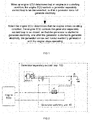
Fig. 1 is a flowchart of the present invention. -
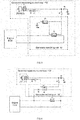
Fig. 2 is a schematic view of a circuit structure according toEmbodiment 1 of the present invention. -
Fig. 3 is a schematic view of a circuit structure according to Embodiment 2 of the present invention. -
Fig. 4 is a schematic view of a circuit structure according to Embodiment 3 of the present invention. -
Fig. 5 is a schematic view of a circuit structure according to Embodiment 4 of the present invention. - The present invention is further described below with reference to embodiments, but does not constitute any limitation to the present invention, and any finite number of modifications made within the scope of the claims of the present invention are still within the scope of the claims of the present invention.
- As shown in
Fig. 1 to Fig. 2 , the present invention provides a vehicle generator control system. An engine ECU controls the generator according to an operating condition of the engine. A control process is as follows:
When the engine ECU determines that the engine is in a starting condition, the engine ECU controls a generator separatelyexcited loop 100 to be disconnected, so that the generator does not generate electricity. - When the engine ECU determines that the engine enters an idling condition, the engine ECU controls the generator separately
excited loop 100 to be closed, so that the generator is started to generate electricity, and after the generator is started to generate electricity, the generator carries out normal electricity generation until the engine stops operating. - The engine ECU determines the operating condition of the engine via an engine speed signal and an engine starting signal, when the engine ECU receives the engine starting signal and the received engine speed signal displays that an engine speed is lower than an idling speed, the engine is in a starting condition, and when the engine speed signal received by the engine ECU displays that the engine speed is equal to the idling speed, the engine is in an idling condition. The generator separately
excited loop 100 is provided with a generator control relay K2, and the engine ECU carries out ON/OFF control on the generator separatelyexcited loop 100 via the generator control relay K2 to control an operation of the generator. The generator control relay K2 is arranged on a controllable circuit connecting in series from an excitation positive terminal D+ of the generator to a positive electrode of a storage battery B1. - In the present embodiment, after receiving the engine speed signal and the engine starting signal, the engine ECU controls the generator control relay K2 to act, such that the generator separately
excited loop 100 is disconnected to make the generator G unable to generate electricity. When receiving an engine speed signal indicating that the engine enters an idling condition, the engine ECU controls the generator control relay K2 to act, such that the generator separatelyexcited loop 100 is closed, the storage battery B1 provides a separate excitation current for the generator G, and the generator G generates electricity. Then, when the engine normally operates, the generator G is able to generate electricity, while the generator G is able to carry out self-excitation electricity generation after normal electricity generation. - In the present embodiment, the engine speed signal and the engine starting signal are obtained by signal detection by the existing detecting device of the vehicle and are provided for the engine ECU. The engine enters an idling range of 600-800 rpm.
- As shown in
Fig. 2 , the present invention provides a vehicle generator control system, including an engine ECU and a storage battery B1, and further including agenerator switching unit 10 connected using signals to the engine ECU and adapted to carry out ON/OFF control on a generator separatelyexcited loop 100. One end of thegenerator switching unit 10 is connected to an excitation positive terminal D+ of a generator via a first diode D1 for preventing a generator excitation coil from generating a reverse voltage, and the other end of thegenerator switching unit 10 is connected to a positive electrode of the storage battery B1 via an ignition switch K1, thereby forming a controllable circuit connecting in series from the positive electrode of the storage battery B1 to the excitation positive terminal D+ of the generator, where a negative electrode of the first diode D1 is connected to the excitation positive terminal D+ of the generator. The positive electrode of the storage battery B1 is connected to a positive output terminal B+ of the generator G, a negative electrode of the storage battery B1 is connected to a ground GND, and an indicator L1 is also provided on a branch where the positive electrode of the storage battery B1 is connected to the excitation positive terminal D+ of the generator G. - The
generator control unit 10 is provided with a generator control relay K2, a coil of the generator control relay K2 is connected in parallel with the engine ECU, and a contact of the generator control relay K2 is connected in series to the controllable circuit from the positive electrode of the storage battery B1 to the excitation positive terminal D+ of the generator, where one end of the contact of the generator control relay K2 is connected to the ignition switch K1 and the other end of the contact the generator control relay K2 is connected to the first diode D1. - In the present embodiment, the contact of the generator control relay K2 is a normally closed contact. The first diode D1 can effectively avoid the influence of the reverse voltage generated by the generator excitation coil on the entire circuit.
- In the present embodiment, after receiving the engine speed signal and the engine starting signal, the engine ECU controls the coil of the generator control relay K2 to be energized to make the contact of the generator control relay K2 disconnected, such that the generator separately
excited loop 100 is disconnected to make the generator G unable to generate electricity. When receiving an engine speed signal indicating that the engine enters an idling condition, the engine ECU controls the coil of the generator control relay K2 to be de-energized to make the contact of the generator control relay K2 closed, such that the generator separatelyexcited loop 100 is closed, the storage battery B1 provides a separate excitation current for the generator G, and the generator G generates electricity. Then, when the engine normally operates, the generator G is able to generate electricity, while the generator G is able to carry out self-excitation electricity generation after normal electricity generation. - As shown in
Fig. 3 , the present invention provides a vehicle generator control system, including an engine ECU and a storage battery B1, and further including agenerator switching unit 10 connected using signals to the engine ECU and adapted to carry out ON/OFF control on a generator separatelyexcited loop 100. One end of thegenerator switching unit 10 is connected to an excitation positive terminal D+ of a generator via a first diode D1 for preventing a generator excitation coil from generating a reverse voltage, and the other end of thegenerator switching unit 10 is connected to a positive electrode of the storage battery B1 via an ignition switch K1, thereby forming a controllable circuit connecting in series from the positive electrode of the storage battery B1 to the excitation positive terminal D+ of the generator, where a negative electrode of the first diode D1 is connected to the excitation positive terminal D+ of the generator. The positive electrode of the storage battery B1 is connected to a positive output terminal B+ of the generator G, a negative electrode of the storage battery B1 is connected to a ground GND, and an indicator L1 is also provided on a branch where the positive electrode of the storage battery B1 is connected to the excitation positive terminal D+ of the generator G. - The
generator control unit 10 is provided with a generator control relay K2 and a first control relay K3 for the generator control relay K2 connected in series to the controllable circuit from the positive electrode of the storage battery B1 to the excitation positive terminal D+ of the generator G, and a coil of the first control relay K3 is connected in series to a contact of the generator control relay K2, where an end of the generator control relay K2 opposite to the contact of the generator control relay K2 connecting to the ignition switch K1 is connected to the coil of the first control relay K3, and an end of the first control relay K3 opposite to a connecting end of the coil of the first control relay K3 connecting to the contact of the generator control relay K2 is connected to a ground GND. A contact of the first control relay K3 is connected in series to the controllable circuit from the positive electrode of the storage battery B1 to the excitation positive terminal D+ of the generator G, where one end of the contact of the first control relay K3 is connected to the ignition switch K1 and the other end of the contact of the first control relay K3 is connected to the first diode D1, the contact of the generator control relay K2 is a normally open contact, and the contact of the first control relay K3 is a normally closed contact. - In the present embodiment, after receiving the engine speed signal and the engine starting signal, the engine ECU controls the contact of the generator control relay K2 to be closed to make the contact of the first control relay K3 disconnected, such that the generator separately
excited loop 100 is disconnected to make the generator G unable to generate electricity. When receiving an engine speed signal indicating that the engine enters an idling condition, the engine ECU controls the contact of the generator control relay K2 to be disconnected to make the contact of the first control relay K3 closed, such that the generator separatelyexcited loop 100 is closed, the storage battery B1 provides a separate excitation current for the generator G, and the generator G generates electricity. Then, when the engine normally operates, the generator G is able to generate electricity, while the generator G is able to carry out self-excitation electricity generation after normal electricity generation. - As shown in
Fig. 4 , a difference from Embodiment 2 is that the coil of the generator control relay K2 is connected in parallel with the engine ECU after being connected in series to a second diode D2 for preventing instantaneous generation of a reverse voltage due to disconnection of the coil of the generator control relay K2, and the engine ECU is further connected in parallel with a coil of a starter control relay K4. The contact of the generator control relay K2 is a time-delay closed normally closed contact. - In the present embodiment, the second diode D2 is provided to prevent instantaneous generation of the reverse voltage due to disconnection of the coil of the generator control relay K2, thereby avoiding interference on the line diagnosis and control of the starter control relay K4 caused by the influence of the reverse voltage on the engine ECU. The engine ECU controls the generator control relay K2 and the starter control relay K4, and the generator control relay K2 carries out time delay closing, which can effectively improve control precision and accuracy. The contact of the starter control relay K4 is a normally open contact.
- In the present embodiment, during operation, after receiving the engine speed signal and the engine starting signal, the engine ECU controls the starter control relay K4 to be closed and also controls the coil of the generator control relay K2 to be energized to make the contact of the generator control relay K2 disconnected, such that the generator separately
excited loop 100 is disconnected to make the generator G unable to generate electricity. When receiving an engine speed signal indicating that the engine enters an idling condition, the engine ECU controls the starter control relay K4 to be disconnected and also controls the contact of the generator control relay K2 to be closed and energized after time delay, such that the generator separatelyexcited loop 100 is closed, the storage battery B1 provides a separate excitation current for the generator G, and the generator G generates electricity. Then, when the engine normally operates, the generator G is able to generate electricity, while the generator G is able to carry out self-excitation electricity generation after normal electricity generation. - As shown in
Fig. 5 , a difference from Embodiment 4 is that thegenerator control unit 10 is provided with a generator control relay K2 and a second control relay K5 for the generator control relay K2 connected in series to the controllable circuit from the positive electrode of the storage battery B1 to the excitation positive terminal D+ of the generator G, and a coil of the second control relay K5 is connected in series to a contact of the generator control relay K2, where an end of the generator control relay K2 opposite to a connecting end of the contact of the generator control relay K2 connecting to the ignition switch K1 is connected to the coil of the second control relay K5, and an end of the second control relay K5 opposite to a connecting end of the coil of the second control relay K5 connecting to the contact of the generator control relay K2 is connected to a ground GND. A contact of the second control relay K5 is connected in series to the controllable circuit from the positive electrode of the storage battery B1 to the excitation positive terminal D+ of the generator G, where one end of the contact of the second control relay K5 is connected to the ignition switch K1 and the other end of the contact of the second control relay K5 is connected to the first diode D1, the contact of the generator control relay K2 is a time-delay disconnected normally open contact, and the contact of the second control relay K5 is a normally closed contact. - In the present embodiment, during operation, after receiving the engine speed signal and the engine starting signal, the engine ECU controls the starter control relay K4 to be closed and also controls the contact of the generator control relay K2 to be closed to make the second control relay K5 disconnected, such that the generator separately
excited loop 100 is disconnected to make the generator G unable to generate electricity. When receiving an engine speed signal indicating that the engine enters an idling condition, the engine ECU controls the starter control relay K4 to be disconnected and also controls the contact of the generator control relay K2 to be disconnected after time delay to make the second control relay K5 closed, such that the generator separatelyexcited loop 100 is closed, the storage battery B1 provides a separate excitation current for the generator G, and the generator G generates electricity. Then, when the engine normally operates, the generator G is able to generate electricity, while the generator G is able to carry out self-excitation electricity generation after normal electricity generation. - The engine ECU simultaneously controls the generator control relay K2 and the starter control relay K4, and the generator control relay K2 carries out time delay disconnection to control the second control relay K5 to be closed, which can effectively improve the control precision and accuracy.
- The above is only a preferred implementation of the present invention, and it should be noted that those skilled in the art can make various modifications and improvements without departing from the structure of the present invention, and such modifications and improvements do not affect the implementation effects and applicability of the present invention.
Claims (6)
- A vehicle generator control system comprising an engine ECU and a storage battery (B1), and a generator switching unit (10) connected for using signals to the engine ECU and adapted to carry out ON/OFF control on a generator separately excited loop (100), the vehicle generator control system configured for executing a vehicle generator control method wherein the engine ECU controls a generator according to an operating condition of an engine, and wherein, when the engine ECU determines that the engine is in a starting condition, the engine ECU controls a generator separately excited loop (100) to be disconnected, so that the generator does not generate electricity; and when the engine ECU determines that the engine enters an idling condition, the engine ECU controls the generator separately excited loop (100) to be closed so that the generator is started to generate electricity, and after the generator is started to generate electricity, the generator carries out normal electricity generation until the engine stops operating; wherein one end of the generator switching unit (10) is connected to an excitation positive terminal (D+) of a generator, and the other end of the generator switching unit (10) is connected to a positive electrode of the storage battery (B1) via an ignition switch (K1), thereby forming a controllable circuit connecting in series from the positive electrode of the storage battery (B1) to the excitation positive terminal (D+) of the generator, characterized in that
the one end of the generator switching unit (10) is connected to the excitation positive terminal (D+) of a generator via a first diode (D1) for preventing a generator excitation coil from generating a reverse voltage, and a negative electrode of the first diode (D1) is connected to the excitation positive terminal (D+) of the generator. - The vehicle generator control system according to claim 1, characterized in that the generator control unit (10) is provided with a generator control relay (K2), a coil of the generator control relay (K2) is connected in parallel with the engine ECU, and a contact of the generator control relay (K2) is connected in series to the controllable circuit from the positive electrode of the storage battery (B1) to the excitation positive terminal (D+) of the generator, one end of the contact of the generator control relay (K2) being connected to the ignition switch (K1) and the other end of the contact of the generator control relay (K2) being connected to the first diode (D1).
- The vehicle generator control system according to claim 1, characterized in that the generator control unit (10) is provided with a first control relay (K3), a coil of the first control relay (K3) connected in series to the contact of the generator control relay (K2) at a connecting end of the generator control relay (K2), wherein an end of the generator control relay (K2) opposite to a connecting end of the contact of the generator control relay (K2) connecting to the ignition switch (K1) is connected to the coil of the first control relay (K3), an end of the first control relay (K3) opposite to a connecting end of the coil of the first control relay (K3) connecting to the contact of the generator control relay (K2) is connected to a ground (GND), a contact of the first control relay (K3) is connected in series to the controllable circuit from the positive electrode of the storage battery (B1) to the excitation positive terminal (D+) of the generator, wherein one end of the contact of the first control relay (K3) is connected to the ignition switch (K1) and the other end of the contact of the first control relay (K3) is connected to the first diode (D1), the contact of the generator control relay (K2) is a normally open contact, and the contact of the first control relay (K3) is a normally closed contact.
- The vehicle generator control system according to claim 2, characterized in that the coil of the generator control relay (K2) is connected in parallel with the engine ECU after being connected in series to a second diode (D2) for preventing instantaneous generation of a reverse voltage due to disconnection of the coil of the generator control relay (K2), and the engine ECU is further connected in parallel with a coil of a starter control relay (K4).
- The vehicle generator control system according to claim 4, characterized in that the contact of the generator control relay (K2) is a time-delay closed normally closed contact.
- The vehicle generator control system according to claim 4, characterized in that, the generator control unit (10) is further provided with a second control relay (K5), the generator control relay (K2) is connected via the second control relay (K5) in series to the controllable circuit from the positive electrode of the storage battery (B1) to the excitation positive terminal (D+) of the generator, a coil of the second control relay (K5) is connected in series to the contact of the generator control relay (K2), wherein an end of the generator control relay (K2) opposite to a connecting end of the contact of the generator control relay (K2) connecting to the ignition switch (K1) is connected to the coil of the second control relay (K5), an end of the second control relay (K5) opposite to a connecting end of the coil of the second control relay (K5) connecting to the contact of the generator control relay (K2) is connected to a ground (GND), a contact of the second control relay (K5) is connected in series to the controllable circuit from the positive electrode of the storage battery (B1) to the excitation positive terminal (D+) of the generator, wherein one end of the contact of the second control relay (K5) is connected to the ignition switch (K1) and the other end of the contact of the second control relay (K5) is connected to the first diode (D1), the contact of the generator control relay (K2) is a time-delay disconnected normally open contact, and the contact of the second control relay (K5) is a normally closed contact.
Applications Claiming Priority (2)
| Application Number | Priority Date | Filing Date | Title |
|---|---|---|---|
| CN201710683856.7A CN107355304B (en) | 2017-08-11 | 2017-08-11 | Control method and system for generator for vehicle |
| PCT/CN2017/106276 WO2019029003A1 (en) | 2017-08-11 | 2017-10-23 | Vehicle generator control method and system thereof |
Publications (3)
| Publication Number | Publication Date |
|---|---|
| EP3553298A1 EP3553298A1 (en) | 2019-10-16 |
| EP3553298A4 EP3553298A4 (en) | 2020-02-26 |
| EP3553298B1 true EP3553298B1 (en) | 2021-01-13 |
Family
ID=60287528
Family Applications (1)
| Application Number | Title | Priority Date | Filing Date |
|---|---|---|---|
| EP17921270.9A Active EP3553298B1 (en) | 2017-08-11 | 2017-10-23 | Vehicle generator control method and system thereof |
Country Status (4)
| Country | Link |
|---|---|
| US (1) | US11002198B2 (en) |
| EP (1) | EP3553298B1 (en) |
| CN (1) | CN107355304B (en) |
| WO (1) | WO2019029003A1 (en) |
Families Citing this family (9)
| Publication number | Priority date | Publication date | Assignee | Title |
|---|---|---|---|---|
| CN107910859B (en) * | 2017-12-28 | 2024-05-17 | 潍柴动力股份有限公司 | Protection device of electronic control unit |
| CN108322114A (en) * | 2018-02-28 | 2018-07-24 | 广西玉柴机器股份有限公司 | A kind of automobile current generator system and start method |
| CN110529267B (en) * | 2019-09-19 | 2022-02-22 | 广西玉柴机器股份有限公司 | Engine electronic control rotating speed control method and system |
| CN111550345B (en) * | 2020-05-29 | 2022-04-26 | 潍柴动力股份有限公司 | Cold start control method and device and electronic equipment |
| CN111806423B (en) * | 2020-06-09 | 2022-06-28 | 联合汽车电子有限公司 | Method for reducing engine load and readable storage medium |
| CN112922762A (en) * | 2021-01-22 | 2021-06-08 | 苏州巩诚电器技术有限公司 | Control method for reducing engine starting load |
| CN112764380B (en) * | 2021-01-25 | 2022-04-29 | 湖北三江航天红峰控制有限公司 | A relay-based aircraft self-destruction control system and its design method |
| CN114718749A (en) * | 2022-05-20 | 2022-07-08 | 中铁通轨道运营有限公司 | Diesel locomotive engine start-stop system and engine start-stop control method |
| CN116653823A (en) * | 2023-05-31 | 2023-08-29 | 中国第一汽车股份有限公司 | Voltage control method, device, equipment and medium for vehicle generator |
Family Cites Families (15)
| Publication number | Priority date | Publication date | Assignee | Title |
|---|---|---|---|---|
| US4463305A (en) * | 1981-12-16 | 1984-07-31 | Ford Motor Company | Alternator load shedder for engine starting improvement |
| JPS61171879A (en) * | 1985-01-28 | 1986-08-02 | Daihatsu Motor Co Ltd | Alternator control device |
| DE4222072C1 (en) * | 1992-07-04 | 1994-03-03 | Bosch Gmbh Robert | Device for regulating the output voltage of a generator driven by an internal combustion engine |
| US7240481B2 (en) * | 2005-03-10 | 2007-07-10 | Gm Global Technology Operations, Inc. | Engine load control for reduced cold start emissions |
| JP2006296016A (en) * | 2005-04-06 | 2006-10-26 | Toshiba Corp | Start control device and method for diesel power generation equipment |
| DE102005035052B4 (en) * | 2005-07-27 | 2017-01-12 | Schaeffler Technologies AG & Co. KG | Method for quickly restarting a deactivated internal combustion engine with a belt-driven starter generator |
| TWI411542B (en) * | 2008-10-24 | 2013-10-11 | Kwang Yang Motor Co | Vehicle start control system |
| US8569903B2 (en) * | 2010-10-27 | 2013-10-29 | Ford Global Technologies, Llc | Methods and systems for improved engine speed control during engine starting |
| DE102010063372A1 (en) * | 2010-12-17 | 2012-06-21 | Robert Bosch Gmbh | Control box i.e. automated parking brake-keyboard, for use in electronics stability control device of switching system of e.g. luxury car, has connection device attaching unit and illumination and switching devices to control device |
| CN201953539U (en) * | 2010-12-31 | 2011-08-31 | 长城汽车股份有限公司 | Car engine start control system capable of improving cold-start performance of whole car |
| CN202325872U (en) * | 2011-10-16 | 2012-07-11 | 济南吉美乐电源技术有限公司 | Remote-control automatic starting controller of generator set |
| CN103023410A (en) * | 2012-12-21 | 2013-04-03 | 重庆磐达机械有限公司 | Double-excitation system for air-cooled generator set |
| CN103615345B (en) | 2013-12-10 | 2016-08-17 | 安徽江淮汽车股份有限公司 | A kind of cold starting system of flexible fuel vehicle |
| CN205044671U (en) * | 2015-09-23 | 2016-02-24 | 宋忠春 | Car power supply system circuit |
| JP2017105365A (en) * | 2015-12-10 | 2017-06-15 | トヨタ自動車株式会社 | Hybrid vehicle driving force control device |
-
2017
- 2017-08-11 CN CN201710683856.7A patent/CN107355304B/en active Active
- 2017-10-23 WO PCT/CN2017/106276 patent/WO2019029003A1/en not_active Ceased
- 2017-10-23 EP EP17921270.9A patent/EP3553298B1/en active Active
- 2017-10-23 US US16/467,986 patent/US11002198B2/en active Active
Non-Patent Citations (1)
| Title |
|---|
| None * |
Also Published As
| Publication number | Publication date |
|---|---|
| CN107355304A (en) | 2017-11-17 |
| WO2019029003A1 (en) | 2019-02-14 |
| EP3553298A1 (en) | 2019-10-16 |
| US20200072138A1 (en) | 2020-03-05 |
| EP3553298A4 (en) | 2020-02-26 |
| US11002198B2 (en) | 2021-05-11 |
| CN107355304B (en) | 2023-08-01 |
Similar Documents
| Publication | Publication Date | Title |
|---|---|---|
| US11002198B2 (en) | Vehicle generator control method and system thereof | |
| JP6465907B2 (en) | Vehicle power supply system | |
| US10263438B2 (en) | Battery management system for vehicle | |
| CN108116350B (en) | Vehicle-mounted combined battery intelligent power supply electrical system and power supply method | |
| RU2013124386A (en) | HYBRID VEHICLE CONTROL DEVICE | |
| US11565603B2 (en) | Vehicle power supply control method and vehicle power supply control device | |
| US9789771B2 (en) | Single battery architecture for electrification vehicle | |
| US20130066519A1 (en) | Electronic control device and vehicle control system | |
| US10302060B2 (en) | Electric power control apparatus | |
| US10498154B2 (en) | Electric power system | |
| CN203554016U (en) | Automatic charge/discharge switching controller for two storage batteries of automobile | |
| CN103618346A (en) | Automobile double-set storage battery charging and discharging automatic switching controller | |
| JP2009025032A (en) | Battery state detection device and method, and output control device and method | |
| CN201953539U (en) | Car engine start control system capable of improving cold-start performance of whole car | |
| JP2019009910A (en) | Power unit for vehicle | |
| CN207033600U (en) | Alternator for vehicle control system | |
| JP4930420B2 (en) | In-vehicle power supply | |
| CN105332806B (en) | A kind of intelligent energy-saving controller | |
| US9667059B2 (en) | Battery protection device and battery device | |
| CN220204032U (en) | Automobile starting control circuit | |
| RU230872U1 (en) | Generator Set Start Controller | |
| RU2118695C1 (en) | Vehicle electrical system | |
| CN201874716U (en) | Assisted starting device of automobile | |
| JP2011050222A (en) | Power supply device for vehicle | |
| JP2026068279A (en) | Method for detecting ON sticking of the system main relay |
Legal Events
| Date | Code | Title | Description |
|---|---|---|---|
| STAA | Information on the status of an ep patent application or granted ep patent |
Free format text: STATUS: THE INTERNATIONAL PUBLICATION HAS BEEN MADE |
|
| PUAI | Public reference made under article 153(3) epc to a published international application that has entered the european phase |
Free format text: ORIGINAL CODE: 0009012 |
|
| STAA | Information on the status of an ep patent application or granted ep patent |
Free format text: STATUS: REQUEST FOR EXAMINATION WAS MADE |
|
| 17P | Request for examination filed |
Effective date: 20190708 |
|
| AK | Designated contracting states |
Kind code of ref document: A1 Designated state(s): AL AT BE BG CH CY CZ DE DK EE ES FI FR GB GR HR HU IE IS IT LI LT LU LV MC MK MT NL NO PL PT RO RS SE SI SK SM TR |
|
| A4 | Supplementary search report drawn up and despatched |
Effective date: 20200128 |
|
| RIC1 | Information provided on ipc code assigned before grant |
Ipc: F02N 19/00 20100101ALI20200122BHEP Ipc: F02D 41/06 20060101ALI20200122BHEP Ipc: F02D 29/06 20060101AFI20200122BHEP Ipc: F02N 11/08 20060101ALI20200122BHEP |
|
| GRAP | Despatch of communication of intention to grant a patent |
Free format text: ORIGINAL CODE: EPIDOSNIGR1 |
|
| STAA | Information on the status of an ep patent application or granted ep patent |
Free format text: STATUS: GRANT OF PATENT IS INTENDED |
|
| INTG | Intention to grant announced |
Effective date: 20200924 |
|
| GRAS | Grant fee paid |
Free format text: ORIGINAL CODE: EPIDOSNIGR3 |
|
| GRAA | (expected) grant |
Free format text: ORIGINAL CODE: 0009210 |
|
| STAA | Information on the status of an ep patent application or granted ep patent |
Free format text: STATUS: THE PATENT HAS BEEN GRANTED |
|
| AK | Designated contracting states |
Kind code of ref document: B1 Designated state(s): AL AT BE BG CH CY CZ DE DK EE ES FI FR GB GR HR HU IE IS IT LI LT LU LV MC MK MT NL NO PL PT RO RS SE SI SK SM TR |
|
| REG | Reference to a national code |
Ref country code: GB Ref legal event code: FG4D |
|
| REG | Reference to a national code |
Ref country code: CH Ref legal event code: EP |
|
| REG | Reference to a national code |
Ref country code: IE Ref legal event code: FG4D |
|
| REG | Reference to a national code |
Ref country code: DE Ref legal event code: R096 Ref document number: 602017031538 Country of ref document: DE |
|
| REG | Reference to a national code |
Ref country code: AT Ref legal event code: REF Ref document number: 1354729 Country of ref document: AT Kind code of ref document: T Effective date: 20210215 |
|
| REG | Reference to a national code |
Ref country code: AT Ref legal event code: MK05 Ref document number: 1354729 Country of ref document: AT Kind code of ref document: T Effective date: 20210113 |
|
| REG | Reference to a national code |
Ref country code: NL Ref legal event code: MP Effective date: 20210113 |
|
| REG | Reference to a national code |
Ref country code: LT Ref legal event code: MG9D |
|
| PG25 | Lapsed in a contracting state [announced via postgrant information from national office to epo] |
Ref country code: NO Free format text: LAPSE BECAUSE OF FAILURE TO SUBMIT A TRANSLATION OF THE DESCRIPTION OR TO PAY THE FEE WITHIN THE PRESCRIBED TIME-LIMIT Effective date: 20210413 Ref country code: PT Free format text: LAPSE BECAUSE OF FAILURE TO SUBMIT A TRANSLATION OF THE DESCRIPTION OR TO PAY THE FEE WITHIN THE PRESCRIBED TIME-LIMIT Effective date: 20210513 Ref country code: GR Free format text: LAPSE BECAUSE OF FAILURE TO SUBMIT A TRANSLATION OF THE DESCRIPTION OR TO PAY THE FEE WITHIN THE PRESCRIBED TIME-LIMIT Effective date: 20210414 Ref country code: FI Free format text: LAPSE BECAUSE OF FAILURE TO SUBMIT A TRANSLATION OF THE DESCRIPTION OR TO PAY THE FEE WITHIN THE PRESCRIBED TIME-LIMIT Effective date: 20210113 Ref country code: HR Free format text: LAPSE BECAUSE OF FAILURE TO SUBMIT A TRANSLATION OF THE DESCRIPTION OR TO PAY THE FEE WITHIN THE PRESCRIBED TIME-LIMIT Effective date: 20210113 Ref country code: BG Free format text: LAPSE BECAUSE OF FAILURE TO SUBMIT A TRANSLATION OF THE DESCRIPTION OR TO PAY THE FEE WITHIN THE PRESCRIBED TIME-LIMIT Effective date: 20210413 Ref country code: LT Free format text: LAPSE BECAUSE OF FAILURE TO SUBMIT A TRANSLATION OF THE DESCRIPTION OR TO PAY THE FEE WITHIN THE PRESCRIBED TIME-LIMIT Effective date: 20210113 |
|
| PG25 | Lapsed in a contracting state [announced via postgrant information from national office to epo] |
Ref country code: SE Free format text: LAPSE BECAUSE OF FAILURE TO SUBMIT A TRANSLATION OF THE DESCRIPTION OR TO PAY THE FEE WITHIN THE PRESCRIBED TIME-LIMIT Effective date: 20210113 Ref country code: AT Free format text: LAPSE BECAUSE OF FAILURE TO SUBMIT A TRANSLATION OF THE DESCRIPTION OR TO PAY THE FEE WITHIN THE PRESCRIBED TIME-LIMIT Effective date: 20210113 Ref country code: RS Free format text: LAPSE BECAUSE OF FAILURE TO SUBMIT A TRANSLATION OF THE DESCRIPTION OR TO PAY THE FEE WITHIN THE PRESCRIBED TIME-LIMIT Effective date: 20210113 Ref country code: LV Free format text: LAPSE BECAUSE OF FAILURE TO SUBMIT A TRANSLATION OF THE DESCRIPTION OR TO PAY THE FEE WITHIN THE PRESCRIBED TIME-LIMIT Effective date: 20210113 Ref country code: PL Free format text: LAPSE BECAUSE OF FAILURE TO SUBMIT A TRANSLATION OF THE DESCRIPTION OR TO PAY THE FEE WITHIN THE PRESCRIBED TIME-LIMIT Effective date: 20210113 |
|
| PG25 | Lapsed in a contracting state [announced via postgrant information from national office to epo] |
Ref country code: IS Free format text: LAPSE BECAUSE OF FAILURE TO SUBMIT A TRANSLATION OF THE DESCRIPTION OR TO PAY THE FEE WITHIN THE PRESCRIBED TIME-LIMIT Effective date: 20210513 |
|
| REG | Reference to a national code |
Ref country code: DE Ref legal event code: R097 Ref document number: 602017031538 Country of ref document: DE |
|
| PG25 | Lapsed in a contracting state [announced via postgrant information from national office to epo] |
Ref country code: CZ Free format text: LAPSE BECAUSE OF FAILURE TO SUBMIT A TRANSLATION OF THE DESCRIPTION OR TO PAY THE FEE WITHIN THE PRESCRIBED TIME-LIMIT Effective date: 20210113 Ref country code: EE Free format text: LAPSE BECAUSE OF FAILURE TO SUBMIT A TRANSLATION OF THE DESCRIPTION OR TO PAY THE FEE WITHIN THE PRESCRIBED TIME-LIMIT Effective date: 20210113 Ref country code: SM Free format text: LAPSE BECAUSE OF FAILURE TO SUBMIT A TRANSLATION OF THE DESCRIPTION OR TO PAY THE FEE WITHIN THE PRESCRIBED TIME-LIMIT Effective date: 20210113 |
|
| PLBE | No opposition filed within time limit |
Free format text: ORIGINAL CODE: 0009261 |
|
| STAA | Information on the status of an ep patent application or granted ep patent |
Free format text: STATUS: NO OPPOSITION FILED WITHIN TIME LIMIT |
|
| PG25 | Lapsed in a contracting state [announced via postgrant information from national office to epo] |
Ref country code: SK Free format text: LAPSE BECAUSE OF FAILURE TO SUBMIT A TRANSLATION OF THE DESCRIPTION OR TO PAY THE FEE WITHIN THE PRESCRIBED TIME-LIMIT Effective date: 20210113 Ref country code: DK Free format text: LAPSE BECAUSE OF FAILURE TO SUBMIT A TRANSLATION OF THE DESCRIPTION OR TO PAY THE FEE WITHIN THE PRESCRIBED TIME-LIMIT Effective date: 20210113 Ref country code: RO Free format text: LAPSE BECAUSE OF FAILURE TO SUBMIT A TRANSLATION OF THE DESCRIPTION OR TO PAY THE FEE WITHIN THE PRESCRIBED TIME-LIMIT Effective date: 20210113 |
|
| 26N | No opposition filed |
Effective date: 20211014 |
|
| PG25 | Lapsed in a contracting state [announced via postgrant information from national office to epo] |
Ref country code: AL Free format text: LAPSE BECAUSE OF FAILURE TO SUBMIT A TRANSLATION OF THE DESCRIPTION OR TO PAY THE FEE WITHIN THE PRESCRIBED TIME-LIMIT Effective date: 20210113 Ref country code: ES Free format text: LAPSE BECAUSE OF FAILURE TO SUBMIT A TRANSLATION OF THE DESCRIPTION OR TO PAY THE FEE WITHIN THE PRESCRIBED TIME-LIMIT Effective date: 20210113 |
|
| PG25 | Lapsed in a contracting state [announced via postgrant information from national office to epo] |
Ref country code: SI Free format text: LAPSE BECAUSE OF FAILURE TO SUBMIT A TRANSLATION OF THE DESCRIPTION OR TO PAY THE FEE WITHIN THE PRESCRIBED TIME-LIMIT Effective date: 20210113 |
|
| PG25 | Lapsed in a contracting state [announced via postgrant information from national office to epo] |
Ref country code: IT Free format text: LAPSE BECAUSE OF FAILURE TO SUBMIT A TRANSLATION OF THE DESCRIPTION OR TO PAY THE FEE WITHIN THE PRESCRIBED TIME-LIMIT Effective date: 20210113 |
|
| REG | Reference to a national code |
Ref country code: DE Ref legal event code: R119 Ref document number: 602017031538 Country of ref document: DE |
|
| REG | Reference to a national code |
Ref country code: CH Ref legal event code: PL |
|
| PG25 | Lapsed in a contracting state [announced via postgrant information from national office to epo] |
Ref country code: IS Free format text: LAPSE BECAUSE OF FAILURE TO SUBMIT A TRANSLATION OF THE DESCRIPTION OR TO PAY THE FEE WITHIN THE PRESCRIBED TIME-LIMIT Effective date: 20210513 |
|
| REG | Reference to a national code |
Ref country code: BE Ref legal event code: MM Effective date: 20211031 |
|
| GBPC | Gb: european patent ceased through non-payment of renewal fee |
Effective date: 20211023 |
|
| PG25 | Lapsed in a contracting state [announced via postgrant information from national office to epo] |
Ref country code: MC Free format text: LAPSE BECAUSE OF FAILURE TO SUBMIT A TRANSLATION OF THE DESCRIPTION OR TO PAY THE FEE WITHIN THE PRESCRIBED TIME-LIMIT Effective date: 20210113 |
|
| PG25 | Lapsed in a contracting state [announced via postgrant information from national office to epo] |
Ref country code: LU Free format text: LAPSE BECAUSE OF NON-PAYMENT OF DUE FEES Effective date: 20211023 Ref country code: GB Free format text: LAPSE BECAUSE OF NON-PAYMENT OF DUE FEES Effective date: 20211023 Ref country code: DE Free format text: LAPSE BECAUSE OF NON-PAYMENT OF DUE FEES Effective date: 20220503 Ref country code: BE Free format text: LAPSE BECAUSE OF NON-PAYMENT OF DUE FEES Effective date: 20211031 |
|
| PG25 | Lapsed in a contracting state [announced via postgrant information from national office to epo] |
Ref country code: LI Free format text: LAPSE BECAUSE OF NON-PAYMENT OF DUE FEES Effective date: 20211031 Ref country code: CH Free format text: LAPSE BECAUSE OF NON-PAYMENT OF DUE FEES Effective date: 20211031 |
|
| PG25 | Lapsed in a contracting state [announced via postgrant information from national office to epo] |
Ref country code: FR Free format text: LAPSE BECAUSE OF NON-PAYMENT OF DUE FEES Effective date: 20211031 |
|
| PG25 | Lapsed in a contracting state [announced via postgrant information from national office to epo] |
Ref country code: IE Free format text: LAPSE BECAUSE OF NON-PAYMENT OF DUE FEES Effective date: 20211023 |
|
| PG25 | Lapsed in a contracting state [announced via postgrant information from national office to epo] |
Ref country code: NL Free format text: LAPSE BECAUSE OF NON-PAYMENT OF DUE FEES Effective date: 20210113 Ref country code: CY Free format text: LAPSE BECAUSE OF FAILURE TO SUBMIT A TRANSLATION OF THE DESCRIPTION OR TO PAY THE FEE WITHIN THE PRESCRIBED TIME-LIMIT Effective date: 20210113 |
|
| PG25 | Lapsed in a contracting state [announced via postgrant information from national office to epo] |
Ref country code: HU Free format text: LAPSE BECAUSE OF FAILURE TO SUBMIT A TRANSLATION OF THE DESCRIPTION OR TO PAY THE FEE WITHIN THE PRESCRIBED TIME-LIMIT; INVALID AB INITIO Effective date: 20171023 |
|
| PG25 | Lapsed in a contracting state [announced via postgrant information from national office to epo] |
Ref country code: MK Free format text: LAPSE BECAUSE OF FAILURE TO SUBMIT A TRANSLATION OF THE DESCRIPTION OR TO PAY THE FEE WITHIN THE PRESCRIBED TIME-LIMIT Effective date: 20210113 |
|
| PG25 | Lapsed in a contracting state [announced via postgrant information from national office to epo] |
Ref country code: MT Free format text: LAPSE BECAUSE OF FAILURE TO SUBMIT A TRANSLATION OF THE DESCRIPTION OR TO PAY THE FEE WITHIN THE PRESCRIBED TIME-LIMIT Effective date: 20210113 |
|
| PGFP | Annual fee paid to national office [announced via postgrant information from national office to epo] |
Ref country code: TR Payment date: 20251015 Year of fee payment: 9 |