EP3552852A1 - An adhesive bondline spacer clip - Google Patents
An adhesive bondline spacer clip Download PDFInfo
- Publication number
- EP3552852A1 EP3552852A1 EP18167276.7A EP18167276A EP3552852A1 EP 3552852 A1 EP3552852 A1 EP 3552852A1 EP 18167276 A EP18167276 A EP 18167276A EP 3552852 A1 EP3552852 A1 EP 3552852A1
- Authority
- EP
- European Patent Office
- Prior art keywords
- spacer
- vehicle part
- spacer element
- clip
- spacer clip
- Prior art date
- Legal status (The legal status is an assumption and is not a legal conclusion. Google has not performed a legal analysis and makes no representation as to the accuracy of the status listed.)
- Granted
Links
- 125000006850 spacer group Chemical group 0.000 title claims abstract description 202
- 239000000853 adhesive Substances 0.000 title claims abstract description 27
- 230000001070 adhesive effect Effects 0.000 title claims abstract description 27
- 230000003313 weakening effect Effects 0.000 claims description 22
- 238000000034 method Methods 0.000 claims description 12
- 239000000463 material Substances 0.000 claims description 10
- 239000004033 plastic Substances 0.000 claims description 6
- 230000007935 neutral effect Effects 0.000 claims description 5
- 239000012858 resilient material Substances 0.000 claims description 3
- 239000002184 metal Substances 0.000 claims description 2
- ORQBXQOJMQIAOY-UHFFFAOYSA-N nobelium Chemical compound [No] ORQBXQOJMQIAOY-UHFFFAOYSA-N 0.000 description 24
- 239000011324 bead Substances 0.000 description 5
- 230000008901 benefit Effects 0.000 description 4
- OKTJSMMVPCPJKN-UHFFFAOYSA-N Carbon Chemical compound [C] OKTJSMMVPCPJKN-UHFFFAOYSA-N 0.000 description 2
- 229910052799 carbon Inorganic materials 0.000 description 2
- 239000002131 composite material Substances 0.000 description 2
- 238000010146 3D printing Methods 0.000 description 1
- 230000008859 change Effects 0.000 description 1
- 230000001419 dependent effect Effects 0.000 description 1
- 238000009826 distribution Methods 0.000 description 1
- 238000001746 injection moulding Methods 0.000 description 1
- 238000004519 manufacturing process Methods 0.000 description 1
- 230000004048 modification Effects 0.000 description 1
- 238000012986 modification Methods 0.000 description 1
- 238000002360 preparation method Methods 0.000 description 1
- 238000003825 pressing Methods 0.000 description 1
- 230000002787 reinforcement Effects 0.000 description 1
- 229920001169 thermoplastic Polymers 0.000 description 1
- 239000004416 thermosoftening plastic Substances 0.000 description 1
Images


Classifications
-
- B—PERFORMING OPERATIONS; TRANSPORTING
- B60—VEHICLES IN GENERAL
- B60J—WINDOWS, WINDSCREENS, NON-FIXED ROOFS, DOORS, OR SIMILAR DEVICES FOR VEHICLES; REMOVABLE EXTERNAL PROTECTIVE COVERINGS SPECIALLY ADAPTED FOR VEHICLES
- B60J1/00—Windows; Windscreens; Accessories therefor
- B60J1/004—Mounting of windows
- B60J1/005—Mounting of windows using positioning means during mounting
-
- B—PERFORMING OPERATIONS; TRANSPORTING
- B29—WORKING OF PLASTICS; WORKING OF SUBSTANCES IN A PLASTIC STATE IN GENERAL
- B29C—SHAPING OR JOINING OF PLASTICS; SHAPING OF MATERIAL IN A PLASTIC STATE, NOT OTHERWISE PROVIDED FOR; AFTER-TREATMENT OF THE SHAPED PRODUCTS, e.g. REPAIRING
- B29C65/00—Joining or sealing of preformed parts, e.g. welding of plastics materials; Apparatus therefor
- B29C65/78—Means for handling the parts to be joined, e.g. for making containers or hollow articles, e.g. means for handling sheets, plates, web-like materials, tubular articles, hollow articles or elements to be joined therewith; Means for discharging the joined articles from the joining apparatus
- B29C65/7802—Positioning the parts to be joined, e.g. aligning, indexing or centring
- B29C65/782—Positioning the parts to be joined, e.g. aligning, indexing or centring by setting the gap between the parts to be joined
- B29C65/7823—Positioning the parts to be joined, e.g. aligning, indexing or centring by setting the gap between the parts to be joined by using distance pieces, i.e. by using spacers positioned between the parts to be joined and forming a part of the joint
- B29C65/7826—Positioning the parts to be joined, e.g. aligning, indexing or centring by setting the gap between the parts to be joined by using distance pieces, i.e. by using spacers positioned between the parts to be joined and forming a part of the joint said distance pieces being non-integral with the parts to be joined, e.g. particles
-
- B—PERFORMING OPERATIONS; TRANSPORTING
- B23—MACHINE TOOLS; METAL-WORKING NOT OTHERWISE PROVIDED FOR
- B23Q—DETAILS, COMPONENTS, OR ACCESSORIES FOR MACHINE TOOLS, e.g. ARRANGEMENTS FOR COPYING OR CONTROLLING; MACHINE TOOLS IN GENERAL CHARACTERISED BY THE CONSTRUCTION OF PARTICULAR DETAILS OR COMPONENTS; COMBINATIONS OR ASSOCIATIONS OF METAL-WORKING MACHINES, NOT DIRECTED TO A PARTICULAR RESULT
- B23Q3/00—Devices holding, supporting, or positioning work or tools, of a kind normally removable from the machine
- B23Q3/18—Devices holding, supporting, or positioning work or tools, of a kind normally removable from the machine for positioning only
-
- B—PERFORMING OPERATIONS; TRANSPORTING
- B29—WORKING OF PLASTICS; WORKING OF SUBSTANCES IN A PLASTIC STATE IN GENERAL
- B29C—SHAPING OR JOINING OF PLASTICS; SHAPING OF MATERIAL IN A PLASTIC STATE, NOT OTHERWISE PROVIDED FOR; AFTER-TREATMENT OF THE SHAPED PRODUCTS, e.g. REPAIRING
- B29C65/00—Joining or sealing of preformed parts, e.g. welding of plastics materials; Apparatus therefor
- B29C65/48—Joining or sealing of preformed parts, e.g. welding of plastics materials; Apparatus therefor using adhesives, i.e. using supplementary joining material; solvent bonding
- B29C65/52—Joining or sealing of preformed parts, e.g. welding of plastics materials; Apparatus therefor using adhesives, i.e. using supplementary joining material; solvent bonding characterised by the way of applying the adhesive
-
- B—PERFORMING OPERATIONS; TRANSPORTING
- B62—LAND VEHICLES FOR TRAVELLING OTHERWISE THAN ON RAILS
- B62D—MOTOR VEHICLES; TRAILERS
- B62D27/00—Connections between superstructure or understructure sub-units
- B62D27/02—Connections between superstructure or understructure sub-units rigid
- B62D27/026—Connections by glue bonding
-
- F—MECHANICAL ENGINEERING; LIGHTING; HEATING; WEAPONS; BLASTING
- F16—ENGINEERING ELEMENTS AND UNITS; GENERAL MEASURES FOR PRODUCING AND MAINTAINING EFFECTIVE FUNCTIONING OF MACHINES OR INSTALLATIONS; THERMAL INSULATION IN GENERAL
- F16B—DEVICES FOR FASTENING OR SECURING CONSTRUCTIONAL ELEMENTS OR MACHINE PARTS TOGETHER, e.g. NAILS, BOLTS, CIRCLIPS, CLAMPS, CLIPS OR WEDGES; JOINTS OR JOINTING
- F16B11/00—Connecting constructional elements or machine parts by sticking or pressing them together, e.g. cold pressure welding
- F16B11/006—Connecting constructional elements or machine parts by sticking or pressing them together, e.g. cold pressure welding by gluing
Definitions
- the present invention relates to a spacer clip for ensuring a minimum adhesive bond line thickness during an attachment event for attaching a first vehicle part with a second vehicle part.
- the present invention also relates to a method for attaching a first vehicle part and a second vehicle part to each other.
- the vehicle parts are bonded to each other with an adhesive.
- the performance of the adhesive depends on the adhesive itself but also for instance on the preparation of the vehicle parts surfaces in the bond line between the parts and on the bond line thickness.
- the thickness and uniformity of the bond line between the vehicle parts is of high importance for the quality of the bond joint.
- a non-uniform bond line may cause air pockets and stress in the cured adhesive in the bond line area.
- a too thin or too thick bond joint between the vehicle parts may not provide the desired strength or stress acceptance of the bond.
- the beads that define the bond line thickness since it is the beads that define the bond line thickness, and the beads are part of the adhesive, it is relatively cumbersome to change the bond line thickness from a one thickness for one bond to joint to another second thickness for another bond joint. Further, the size distribution of the beads may not be sufficiently narrow to provide the desired uniformity of the bond line. In addition, the beads may be too small for some applications.
- a spacer clip for ensuring a minimum adhesive bond line thickness during an attachment event for attaching a first vehicle part with a second vehicle part
- the spacer clip comprises: a spacer element having a thickness defining the minimum bond line thickness, the spacer element is adapted to be arranged interleaved between the first vehicle part and the second vehicle part when attaching the first vehicle part with the second vehicle part, a hold portion generally parallel with the spacer element, the hold portion is attached to the spacer element with an interconnecting portion, wherein the spacer clip is mountable on the first vehicle part, wherein the hold portion is adapted to be arranged on an opposite side of the first vehicle part compared to the spacer element during the attachment event, wherein, the spacer element and the hold portion are adapted to maintain a pressure on the first vehicle part such that the spacer clip can be mounted on the first vehicle part prior to the attachment event and maintain mounted on the vehicle part during the attachment event.
- the present invention is based on the realization of a spacer clip which may be mounted on one of the vehicle parts prior to the attachment of the vehicle parts to each other.
- the spacer clip may be clipped onto the first vehicle part to ensure a minimum gap between the first vehicle part and the second vehicle part, whereby the minimum gap is defined by the thickness of the spacer element of the spacer clip which thereby defines the minimum desired bond line thickness.
- Advantages of the invention include improved performance of the control of the minimum bond line thickness for varying tolerances of the vehicle parts and faster manufacturing flow since the spacer clips may be clipped on the vehicle parts before the attachment event.
- the hold portion and the spacer element are configured as a "clip" with a spacing between the hold portion and the spacer element.
- the spacer clip is configured to be clipped onto the first vehicle part with the first vehicle part in the spacing.
- the spacing may be an air gap.
- the interconnecting portion links the spacer element to the hold portion.
- the spacer element may be generally planar in order to provide improved uniformity of the bond line thickness. Furthermore, the spacer element may have a uniform thickness corresponding to the desired bond line thickness. In this way, the uniformity may be even further improved.
- the interconnecting portion may comprise a resilient material such that when the spacer element and the hold portion are forced further apart from each other from a neutral position, the interconnecting portion attempts to bring the spacer element and the hold portion back to the neutral position.
- the resilience in the interconnecting portion may provide the required force for clipping the spacer clip onto the first vehicle part.
- the spacer clip may comprise a plastic material such as a thermoplastic.
- the entire spacer clip may be formed from the same material.
- the spacer clip may in some embodiments be generally U-shaped which is well suitable for clipping the spacer clip onto a vehicle part.
- the spacer element, the hold portion and the interconnecting portion may be made in a single piece.
- the spacer element may comprise at least one weakening groove such that the spacer clip may be separated in two pieces at the weakening grooves. This advantageously provides for improved possibilities to remove part of the spacer clip from the adhered vehicle parts after the attachment event.
- the part of the spacer element that is left is interleaved between the first and the second vehicle part.
- the weakening groove is located in the spacer element, wherein only a remaining portion of the spacer element is left interleaved between the first and second vehicle part.
- the weakening groove is located in the interconnecting portion, wherein when the spacer clip is separated into two pieces, the spacer element remains interleaved between the vehicle parts and at least a portion of the interconnecting portion is maintained connected with the spacer element.
- the weakening grooves may be on opposite sides of the spacer element, one on the side facing the gap between the hold portion and the spacer element, and another weakening groove on the outer surface of the spacer element.
- the location of one or more weakening grooves may be tailored depending on where it is desirable to break off the spacer clip after an attachment event.
- a width of the spacer element may advantageously be larger than the thickness of the spacer element.
- the width is taken in a plane parallel to the plane of the bond line.
- the first vehicle part may be adapted to face the interior of a vehicle and the second vehicle part may be adapted to face the exterior of the vehicle.
- the first and second vehicle part may be nearly any vehicle parts that are attached together using an adhesive.
- one of the vehicle parts may be an exterior (interior) carbon composite (or plastic) part adhered to an interior (exterior) (e.g. metallic) flange.
- one of the vehicle parts may be a reinforcement element (e.g. carbon composite or plastic) and the other one a vehicle beam (e.g. a metallic beam).
- the invention is thus applicable to a vast amount of vehicle parts.
- a method for attaching a first vehicle part and a second vehicle part to each other comprising: providing a spacer clip comprising a spacer element and a hold portion generally parallel with the spacer element, wherein the spacer element is connected to the hold portion with an interconnecting portion, the spacer element having a thickness defining the bond line thickness, attaching at least one spacer clip on the first vehicle part, wherein the spacer element and the hold portion are adapted to maintain a pressure on the first vehicle part in such a way that the at least one spacer clip maintains mounted on the first vehicle part, providing the second vehicle part; attaching the second vehicle part to the first vehicle part with an adhesive wherein the spacer element of the at least one spacer clip is arranged interleaved with the first vehicle part and the second vehicle part such that the thickness of the adhesive is defined by the thickness of the spacer element.
- a plurality of spacer clips are attached on the first vehicle part with a random pitch between the spacer clips.
- the random pitch may be any arbitrary pitch suitable for the application.
- Attaching the spacer clip on the first vehicle part may comprise forcing the spacer clip onto the first vehicle part with the spacer element and the hold portion on opposite sides of the first vehicle part.
- the method may include braking off the spacer clip at predefined grooves in the spacer element, leaving only the remaining portion of the spacer element interleaved between the first vehicle part and the second vehicle part.
- the material of the first vehicle part may be different from the material of the second vehicle part in some embodiments.
- the first vehicle part may comprise metal.
- This second aspect of the invention provides similar advantages as discussed above in relation to the previous aspect of the invention.
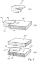
- Fig. 1A shows a perspective view of a spacer clip 100 according to embodiments of the invention.
- the spacer clip 100 comprises a spacer element 102 which has a thickness t to define a minimum bond line thickness when attaching a first vehicle part with a second vehicle part using an adhesive, as will be described with reference to subsequent drawings.
- the spacer clip 100 further comprises a hold portion 104 which is generally parallel with the spacer element 102 and spatially separated from the spacer element with a gap 106.
- the hold portion 104 is attached to the spacer element 102 with an interconnecting portion 108.
- the spacer clip 100 is mounted on one of the vehicle parts with the vehicle part in the gap 106 between the hold portion 104 and the spacer portion 102.
- the spacer element is generally planar, at least on the outer surface 110 of the spacer element 102 to provide a flat interface with the vehicle part coming in contact with the outer surface 110 at the attachment event.
- the flat interface provided by outer surface 110 facilitates to provide improved uniformity of the bond line thickness.
- the spacer element 102 may have a uniform thickness t corresponding to the desired bond line thickness.
- Fig. 1B shows a perspective view of another spacer clip 200 according to embodiments of the invention.
- a difference between the spacer clip 100 described with reference to fig. 1A and the spacer clip 200 is a weakening groove 202 in the spacer element 102 that extends across the width ( L3 , see fig. 2B ) of the spacer clip 200.
- This weakening groove 202 enables to easily break the spacer element 102 at the weakening groove 202 after the attachment event, leaving only a remaining portion 111 of the spacer element 102, which portion 111 is interleaved between the vehicle parts.
- the depth of the weakening groove may be at least half the thickness t of the spacer element 102, or even at least 75% of the thickness t of the spacer element 102, but at most 95% of the thickness t of the spacer element 102.
- a weakening groove 203 may alternatively or additionally be located on the inner side of the spacer element 102 facing the gap 106.
- a weakening groove may be located in various locations according to possible implementations of the inventive concept. For example, as illustrated in fig. 1C presenting a possible spacer clip 300, a weakening groove 204 in the spacer element 102 may be located further away from the interconnecting portion 108 compared to the groove 202. In addition, more than one groove may be combined on spacer clip. For instance, groove 202 and groove 204.
- FIG. 1D Another example spacer clip 400 is illustrated in fig. 1D , in which one or more weakening grooves 205, 206 have been made in the interconnecting portion 108, preferably in line with the inner surface of the spacer element 108 and/or the inner surface facing the gap 106 of the hold portion. Alternatively or additionally, a weakening groove 208 has been made on the side of the interconnecting portion facing the gap 106.
- a weakening groove is made in the hold portion 104 as shown in fig. 1E .
- the location of one or more weakening grooves may be tailored depending on where it is desirable to break off the spacer clip after an attachment event.
- the spacer clips 100,200, 300, 400, 500 are preferably made from a plastic material and may be made in a single piece.
- the spacer clips may be manufactured by e.g. injection molding or 3D-printing techniques.
- the spacer clips 100, 200, 300, 400, 400 conceptually illustrated in figs. 1A-E are generally U-shaped.
- Fig. 2A conceptually illustrates a cross-sectional view of a first vehicle part 202 attached to a second vehicle part 204 with an adhesive 206 and with the use of a spacer clip 100.
- the spacer clip 100 comprises a spacer element 102 with length L2 and a hold portion 104 with length L1 which is larger than L2 in this example embodiment. In other embodiments, the length L1 of the hold portion 104 may be smaller than the length L2 of the spacer element.
- the hold portion 104 and the spacer element 102 are interconnected via the interconnecting portion 108.
- the spacer element 102 is arranged interleaved between the first vehicle part 202 and the second vehicle part 204.
- the first vehicle part 202 is adapted to be arranged on a vehicle interior side and the second vehicle part 204 is adapted to be arranged on a vehicle exterior side.
- the first vehicle part 202 is adapted to be arranged on a vehicle exterior side and the second vehicle part 204 is adapted to be arranged on a vehicle interior side.
- the hold portion 104 which is generally parallel with the spacer element 102 is arranged on an opposite side of the first vehicle part 202 compared to the spacer element 102. Thus, a portion of the first vehicle part 202 is sandwiched between the hold portion 104 and the spacer element 102.
- the spacer element 102 and the hold portion 104 are adapted to maintain a pressure on the first vehicle part 202 such that the spacer clip can be mounted on the first vehicle part 202 prior to attaching the second vehicle part 204 to the first vehicle part 202 with the adhesive 206.
- the bond line width w is the overlapping portion between the first vehicle part 202 and the second vehicle part 204.
- Fig. 2B conceptually illustrates the attached vehicle parts 202, 204 in fig. 2A from the vehicle interior side, here with two spacer clips 100 arranged with a separating pitch D .
- the width L3 of the spacer element 102 is generally larger than the thickness t (see fig. 2A ).
- the bond line length ( L ) is the length of the adhesive bond joint between the vehicle parts 202, 204.
- Fig. 3 conceptually illustrates an attachment event for attaching two vehicle parts 202, 204 to each other.
- a spacer clip 100 according to any one of the described embodiments is provided in step S302, although here the spacer clip 100 is illustrated.
- the spacer clip 100 is attached to a first vehicle part 202 in step S304.
- the interconnecting portion 108 comprises a resilient material such as a plastic material which, when the spacer element 102 and the hold portion 104 are forced further apart by the first vehicle part 202 being inserted in the gap 106 between the spacer element 102 and the hold portion 104, the resilient interconnecting portion 108 attempts to bring the spacer element 102 and the hold portion 104 back to the neutral position thereby applying pressure on the first vehicle part 202. In this way, the spacer clip 100 can be mounted on the first vehicle part 202 prior to the attachment event and maintain mounted on the vehicle part during the attachment event.
- a second vehicle part 204 is attached to the first vehicle part 202 with an adhesive (not shown, see figs. 2A-B ) with the spacer element of the spacer clip 100 interleaved between the first vehicle part 202 and the second vehicle part 204 such that the minimum thickness of the adhesive is defined by the thickness of the spacer element.
- Fig. 4 is a flow-chart of method steps according to embodiments of the invention.
- a spacer clip is provided in step S102.
- the spacer clip comprises a spacer element and a hold portion generally parallel with the spacer element.
- the spacer element is connected to the hold portion with an interconnecting portion and the spacer element has a thickness defining the minimum bond line thickness.
- step S104 at least one spacer clip is attached on the first vehicle.
- the spacer element and the hold portion of each spacer clip are adapted to maintain a pressure on the first vehicle part in such a way that the at least one spacer clip maintains mounted on the first vehicle part.
- a second vehicle part is provided.
- the second vehicle part is attached (S108) to the first vehicle part with an adhesive, wherein the spacer element of the at least one spacer clip is arranged interleaved with the first vehicle part and the second vehicle part such that the thickness of the adhesive is defined by the thickness of the spacer element.
- the spacer clip broken off S110 at predefined grooves is leaving only at least a remaining portion of the spacer element interleaved between the first vehicle part and the second vehicle part.
- the other part of the spacer clip may be removed from the remaining portion of the spacer clip.
Abstract
Description
- The present invention relates to a spacer clip for ensuring a minimum adhesive bond line thickness during an attachment event for attaching a first vehicle part with a second vehicle part. The present invention also relates to a method for attaching a first vehicle part and a second vehicle part to each other.
- In the assembly of a vehicle, some of the vehicle parts are bonded to each other with an adhesive. The performance of the adhesive depends on the adhesive itself but also for instance on the preparation of the vehicle parts surfaces in the bond line between the parts and on the bond line thickness.
- The thickness and uniformity of the bond line between the vehicle parts is of high importance for the quality of the bond joint. A non-uniform bond line may cause air pockets and stress in the cured adhesive in the bond line area. Furthermore, a too thin or too thick bond joint between the vehicle parts may not provide the desired strength or stress acceptance of the bond.
- One way to control the thickness of the bond line is described in
US2010/0143722 , which discloses to use an adhesive which contains beads of a desired size for the bond line thickness. - However, since it is the beads that define the bond line thickness, and the beads are part of the adhesive, it is relatively cumbersome to change the bond line thickness from a one thickness for one bond to joint to another second thickness for another bond joint. Further, the size distribution of the beads may not be sufficiently narrow to provide the desired uniformity of the bond line. In addition, the beads may be too small for some applications.
- Accordingly, there appears to be room for improvements with regards to controlling the adhesion bond line thickness for bonding materials to each other.
- In view of above, it is an object of the present invention to provide a spacer clip for ensuring a minimum adhesive bond line thickness that alleviates at least one of the drawbacks of prior art.
- According to a first aspect of the invention, there is provided a spacer clip for ensuring a minimum adhesive bond line thickness during an attachment event for attaching a first vehicle part with a second vehicle part, the spacer clip comprises: a spacer element having a thickness defining the minimum bond line thickness, the spacer element is adapted to be arranged interleaved between the first vehicle part and the second vehicle part when attaching the first vehicle part with the second vehicle part, a hold portion generally parallel with the spacer element, the hold portion is attached to the spacer element with an interconnecting portion, wherein the spacer clip is mountable on the first vehicle part, wherein the hold portion is adapted to be arranged on an opposite side of the first vehicle part compared to the spacer element during the attachment event, wherein, the spacer element and the hold portion are adapted to maintain a pressure on the first vehicle part such that the spacer clip can be mounted on the first vehicle part prior to the attachment event and maintain mounted on the vehicle part during the attachment event.
- The present invention is based on the realization of a spacer clip which may be mounted on one of the vehicle parts prior to the attachment of the vehicle parts to each other. The spacer clip may be clipped onto the first vehicle part to ensure a minimum gap between the first vehicle part and the second vehicle part, whereby the minimum gap is defined by the thickness of the spacer element of the spacer clip which thereby defines the minimum desired bond line thickness.
- Advantages of the invention include improved performance of the control of the minimum bond line thickness for varying tolerances of the vehicle parts and faster manufacturing flow since the spacer clips may be clipped on the vehicle parts before the attachment event.
- The hold portion and the spacer element are configured as a "clip" with a spacing between the hold portion and the spacer element. The spacer clip is configured to be clipped onto the first vehicle part with the first vehicle part in the spacing. The spacing may be an air gap.
- The interconnecting portion links the spacer element to the hold portion.
- The spacer element may be generally planar in order to provide improved uniformity of the bond line thickness. Furthermore, the spacer element may have a uniform thickness corresponding to the desired bond line thickness. In this way, the uniformity may be even further improved.
- In embodiments, the interconnecting portion may comprise a resilient material such that when the spacer element and the hold portion are forced further apart from each other from a neutral position, the interconnecting portion attempts to bring the spacer element and the hold portion back to the neutral position. Thus, the resilience in the interconnecting portion may provide the required force for clipping the spacer clip onto the first vehicle part.
- The spacer clip may comprise a plastic material such as a thermoplastic. The entire spacer clip may be formed from the same material. The spacer clip may in some embodiments be generally U-shaped which is well suitable for clipping the spacer clip onto a vehicle part.
- The spacer element, the hold portion and the interconnecting portion may be made in a single piece.
- According to embodiments, the spacer element may comprise at least one weakening groove such that the spacer clip may be separated in two pieces at the weakening grooves. This advantageously provides for improved possibilities to remove part of the spacer clip from the adhered vehicle parts after the attachment event. The part of the spacer element that is left is interleaved between the first and the second vehicle part. In one possible implementation, the weakening groove is located in the spacer element, wherein only a remaining portion of the spacer element is left interleaved between the first and second vehicle part. In another possible implementation, the weakening groove is located in the interconnecting portion, wherein when the spacer clip is separated into two pieces, the spacer element remains interleaved between the vehicle parts and at least a portion of the interconnecting portion is maintained connected with the spacer element.
- Moreover, there may be more than one weakening groove in the spacer element and/or interconnecting portion. The weakening grooves may be on opposite sides of the spacer element, one on the side facing the gap between the hold portion and the spacer element, and another weakening groove on the outer surface of the spacer element.
- Furthermore, there may be one or more weakening grooves in the hold portion.
- Accordingly, the location of one or more weakening grooves may be tailored depending on where it is desirable to break off the spacer clip after an attachment event.
- A width of the spacer element may advantageously be larger than the thickness of the spacer element. The width is taken in a plane parallel to the plane of the bond line. Thereby, the stability of the spacer clip is improved when it has been mounted on the first vehicle part.
- The first vehicle part may be adapted to face the interior of a vehicle and the second vehicle part may be adapted to face the exterior of the vehicle.
- The first and second vehicle part may be nearly any vehicle parts that are attached together using an adhesive. For example, one of the vehicle parts may be an exterior (interior) carbon composite (or plastic) part adhered to an interior (exterior) (e.g. metallic) flange. Alternatively, one of the vehicle parts may be a reinforcement element (e.g. carbon composite or plastic) and the other one a vehicle beam (e.g. a metallic beam). The invention is thus applicable to a vast amount of vehicle parts.
- According to a second aspect of the inventive concept, there is provided a method for attaching a first vehicle part and a second vehicle part to each other, comprising: providing a spacer clip comprising a spacer element and a hold portion generally parallel with the spacer element, wherein the spacer element is connected to the hold portion with an interconnecting portion, the spacer element having a thickness defining the bond line thickness, attaching at least one spacer clip on the first vehicle part, wherein the spacer element and the hold portion are adapted to maintain a pressure on the first vehicle part in such a way that the at least one spacer clip maintains mounted on the first vehicle part, providing the second vehicle part; attaching the second vehicle part to the first vehicle part with an adhesive wherein the spacer element of the at least one spacer clip is arranged interleaved with the first vehicle part and the second vehicle part such that the thickness of the adhesive is defined by the thickness of the spacer element.
- In embodiments, a plurality of spacer clips are attached on the first vehicle part with a random pitch between the spacer clips. The random pitch may be any arbitrary pitch suitable for the application.
- Attaching the spacer clip on the first vehicle part may comprise forcing the spacer clip onto the first vehicle part with the spacer element and the hold portion on opposite sides of the first vehicle part.
- According to some embodiments, the method may include braking off the spacer clip at predefined grooves in the spacer element, leaving only the remaining portion of the spacer element interleaved between the first vehicle part and the second vehicle part.
- The material of the first vehicle part may be different from the material of the second vehicle part in some embodiments. For example, the first vehicle part may comprise metal.
- This second aspect of the invention provides similar advantages as discussed above in relation to the previous aspect of the invention.
- Further features of, and advantages with, the present invention will become apparent when studying the appended claims and the following description. The skilled person realizes that different features of the present invention may be combined to create embodiments other than those described in the following, without departing from the scope of the present invention.
- These and other aspects of the present invention will now be described in more detail, with reference to the appended drawings showing example embodiments of the invention, wherein:
-
Fig. 1A schematically illustrates a spacer clip according to embodiments of the invention; -
Fig 1B schematically illustrates a spacer clip according to embodiments of the invention; -
Fig 1C schematically illustrates a spacer clip according to embodiments of the invention; -
Fig 1D schematically illustrates a spacer clip according to embodiments of the invention; -
Fig 1E schematically illustrates a spacer clip according to embodiments of the invention; -
Figs. 2A-B show conceptual views of an application of example embodiments of the invention; -
Fig. 3 conceptually illustrates an attachment event; and -
Fig. 4 is a flow chart of method steps according to embodiments of the invention. - In the present detailed description, various embodiments of the inventive concept are mainly described with reference to specific embodiments. The invention may, however, be embodied in many different forms and should not be construed as limited to the embodiments set forth herein; rather, these embodiments are provided for thoroughness and completeness, and fully convey the scope of the invention to the skilled person. Like reference characters refer to like elements throughout.
-
Fig. 1A shows a perspective view of aspacer clip 100 according to embodiments of the invention. Thespacer clip 100 comprises aspacer element 102 which has a thickness t to define a minimum bond line thickness when attaching a first vehicle part with a second vehicle part using an adhesive, as will be described with reference to subsequent drawings. Thespacer clip 100 further comprises ahold portion 104 which is generally parallel with thespacer element 102 and spatially separated from the spacer element with agap 106. Thehold portion 104 is attached to thespacer element 102 with an interconnectingportion 108. - During an attachment event for attaching two vehicle parts to each other, the
spacer clip 100 is mounted on one of the vehicle parts with the vehicle part in thegap 106 between thehold portion 104 and thespacer portion 102. The spacer element is generally planar, at least on theouter surface 110 of thespacer element 102 to provide a flat interface with the vehicle part coming in contact with theouter surface 110 at the attachment event. The flat interface provided byouter surface 110 facilitates to provide improved uniformity of the bond line thickness. Furthermore, thespacer element 102 may have a uniform thickness t corresponding to the desired bond line thickness. -
Fig. 1B shows a perspective view of anotherspacer clip 200 according to embodiments of the invention. A difference between thespacer clip 100 described with reference tofig. 1A and thespacer clip 200 is a weakeninggroove 202 in thespacer element 102 that extends across the width (L3, seefig. 2B ) of thespacer clip 200. This weakeninggroove 202 enables to easily break thespacer element 102 at the weakeninggroove 202 after the attachment event, leaving only a remainingportion 111 of thespacer element 102, whichportion 111 is interleaved between the vehicle parts. The depth of the weakening groove may be at least half the thickness t of thespacer element 102, or even at least 75% of the thickness t of thespacer element 102, but at most 95% of the thickness t of thespacer element 102. A weakeninggroove 203 may alternatively or additionally be located on the inner side of thespacer element 102 facing thegap 106. - Moreover, a weakening groove may be located in various locations according to possible implementations of the inventive concept. For example, as illustrated in
fig. 1C presenting apossible spacer clip 300, a weakeninggroove 204 in thespacer element 102 may be located further away from the interconnectingportion 108 compared to thegroove 202. In addition, more than one groove may be combined on spacer clip. For instance, groove 202 andgroove 204. - Another
example spacer clip 400 is illustrated infig. 1D , in which one ormore weakening grooves portion 108, preferably in line with the inner surface of thespacer element 108 and/or the inner surface facing thegap 106 of the hold portion. Alternatively or additionally, a weakeninggroove 208 has been made on the side of the interconnecting portion facing thegap 106. - In yet another
possible spacer clip 500, a weakening groove is made in thehold portion 104 as shown infig. 1E . - Accordingly, the location of one or more weakening grooves may be tailored depending on where it is desirable to break off the spacer clip after an attachment event.
- The spacer clips 100,200, 300, 400, 500 are preferably made from a plastic material and may be made in a single piece. The spacer clips may be manufactured by e.g. injection molding or 3D-printing techniques.
- The spacer clips 100, 200, 300, 400, 400 conceptually illustrated in
figs. 1A-E are generally U-shaped. -
Fig. 2A conceptually illustrates a cross-sectional view of afirst vehicle part 202 attached to asecond vehicle part 204 with an adhesive 206 and with the use of aspacer clip 100. Thespacer clip 100 comprises aspacer element 102 with length L2 and ahold portion 104 with length L1 which is larger than L2 in this example embodiment. In other embodiments, the length L1 of thehold portion 104 may be smaller than the length L2 of the spacer element. Thehold portion 104 and thespacer element 102 are interconnected via the interconnectingportion 108. Thespacer element 102 is arranged interleaved between thefirst vehicle part 202 and thesecond vehicle part 204. Thefirst vehicle part 202 is adapted to be arranged on a vehicle interior side and thesecond vehicle part 204 is adapted to be arranged on a vehicle exterior side. Alternatively, thefirst vehicle part 202 is adapted to be arranged on a vehicle exterior side and thesecond vehicle part 204 is adapted to be arranged on a vehicle interior side. - The
hold portion 104 which is generally parallel with thespacer element 102 is arranged on an opposite side of thefirst vehicle part 202 compared to thespacer element 102. Thus, a portion of thefirst vehicle part 202 is sandwiched between thehold portion 104 and thespacer element 102. Thespacer element 102 and thehold portion 104 are adapted to maintain a pressure on thefirst vehicle part 202 such that the spacer clip can be mounted on thefirst vehicle part 202 prior to attaching thesecond vehicle part 204 to thefirst vehicle part 202 with the adhesive 206. - The bond line width w is the overlapping portion between the
first vehicle part 202 and thesecond vehicle part 204. -
Fig. 2B conceptually illustrates the attachedvehicle parts fig. 2A from the vehicle interior side, here with twospacer clips 100 arranged with a separating pitch D. The width L3 of thespacer element 102 is generally larger than the thickness t (seefig. 2A ). The bond line length (L) is the length of the adhesive bond joint between thevehicle parts -
Fig. 3 conceptually illustrates an attachment event for attaching twovehicle parts spacer clip 100 according to any one of the described embodiments is provided in step S302, although here thespacer clip 100 is illustrated. - The
spacer clip 100 is attached to afirst vehicle part 202 in step S304. The interconnectingportion 108 comprises a resilient material such as a plastic material which, when thespacer element 102 and thehold portion 104 are forced further apart by thefirst vehicle part 202 being inserted in thegap 106 between thespacer element 102 and thehold portion 104, the resilient interconnectingportion 108 attempts to bring thespacer element 102 and thehold portion 104 back to the neutral position thereby applying pressure on thefirst vehicle part 202. In this way, thespacer clip 100 can be mounted on thefirst vehicle part 202 prior to the attachment event and maintain mounted on the vehicle part during the attachment event. - In step S306, a
second vehicle part 204 is attached to thefirst vehicle part 202 with an adhesive (not shown, seefigs. 2A-B ) with the spacer element of thespacer clip 100 interleaved between thefirst vehicle part 202 and thesecond vehicle part 204 such that the minimum thickness of the adhesive is defined by the thickness of the spacer element. -
Fig. 4 is a flow-chart of method steps according to embodiments of the invention. A spacer clip is provided in step S102. The spacer clip comprises a spacer element and a hold portion generally parallel with the spacer element. The spacer element is connected to the hold portion with an interconnecting portion and the spacer element has a thickness defining the minimum bond line thickness. In step S104, at least one spacer clip is attached on the first vehicle. The spacer element and the hold portion of each spacer clip are adapted to maintain a pressure on the first vehicle part in such a way that the at least one spacer clip maintains mounted on the first vehicle part. Subsequently, in step S106, a second vehicle part is provided. The second vehicle part is attached (S108) to the first vehicle part with an adhesive, wherein the spacer element of the at least one spacer clip is arranged interleaved with the first vehicle part and the second vehicle part such that the thickness of the adhesive is defined by the thickness of the spacer element. - Optionally, according to some embodiments, the spacer clip broken off S110 at predefined grooves, is leaving only at least a remaining portion of the spacer element interleaved between the first vehicle part and the second vehicle part. The other part of the spacer clip may be removed from the remaining portion of the spacer clip.
- The person skilled in the art realizes that the present invention by no means is limited to the preferred embodiments described above. On the contrary, many modifications and variations are possible within the scope of the appended claims.
- In the claims, the word "comprising" does not exclude other elements or steps, and the indefinite article "a" or "an" does not exclude a plurality. A single processor or other unit may fulfill the functions of several items recited in the claims. The mere fact that certain measures are recited in mutually different dependent claims does not indicate that a combination of these measures cannot be used to advantage. Any reference signs in the claims should not be construed as limiting the scope.
Claims (15)
- A spacer clip (100;200;300;400;500) for ensuring a minimum adhesive bond line thickness (T) during an attachment event for attaching a first vehicle part (202) with a second vehicle part (204) with an adhesive (206), the spacer clip comprises:- a spacer element (102) having a thickness (t) defining the minimum bond line thickness, the spacer element is adapted to be arranged interleaved between the first vehicle part and the second vehicle part when attaching the first vehicle part with the second vehicle part,- a hold portion (104) generally parallel with the spacer element, the hold portion is attached to the spacer element with an interconnecting portion (106), wherein the spacer clip is mountable on the first vehicle part, wherein the hold portion is adapted to be arranged on an opposite side of the first vehicle part compared to the spacer element during the attachment event, wherein,- the spacer element and the hold portion are adapted to maintain a pressure on the first vehicle part such that the spacer clip can be mounted on the first vehicle part prior to the attachment event and maintain mounted on the vehicle part during the attachment event.
- The spacer clip according to claim 1, wherein the spacer element is generally planar.
- The spacer clip according to claim 1 or 2, wherein the spacer element has a uniform thickness (t) corresponding to the minimum bond line thickness.
- The spacer clip according to any one of the preceding claims, wherein the interconnecting portion comprises a resilient material such that when the spacer element and the hold portion are forced further apart from each other from a neutral position, the interconnecting portion attempts to bring the spacer element and the hold portion back to the neutral position.
- The spacer clip according to any one of the preceding claims, wherein the spacer clip comprises a plastic material.
- The spacer clip according to any one of the preceding claims, wherein the spacer clip is generally U-shaped.
- The spacer clip according to any one of the preceding claims, wherein the spacer element, the hold portion and the interconnecting portion are made in a single piece.
- The spacer clip according to any one of the preceding claims, wherein the spacer clip comprises at least one weakening groove (202,203,204,205,206,208,210) such that the spacer clip may be separated in two pieces at the weakening grooves.
- The spacer clip according to any one of the preceding claims, wherein a width (L3) of the spacer element is larger than the thickness of the spacer element.
- A method for attaching a first vehicle part and a second vehicle part to each other, comprising:- providing (S102) a spacer clip comprising a spacer element and a hold portion generally parallel with the spacer element, wherein the spacer element is connected to the hold portion with an interconnecting portion, the spacer element having a thickness defining a minimum bond line thickness,- attaching (S104) at least one spacer clip on the first vehicle part, wherein the spacer element and the hold portion are adapted to maintain a pressure on the first vehicle part in such a way that the at least one spacer clip maintains mounted on the first vehicle part,- providing (S106) the second vehicle part;- attaching (S108) the second vehicle part to the first vehicle part with an adhesive (206) wherein the spacer element of the at least one spacer clip is arranged interleaved with the first vehicle part and the second vehicle part such that the thickness of the adhesive is defined by the thickness of the spacer element.
- The method according to claim 10, comprising:- attaching a plurality of spacer clips on the first vehicle part with a random pitch between the spacer clips.
- The method according to any one of claim 10 or 11, wherein the attaching the spacer clip on the first vehicle part comprises forcing the spacer clip onto the first vehicle part with the spacer element and the hold portion on opposite sides of the first vehicle part.
- The method according to any one of claim 10 to 12, comprising:- braking (S110) off the spacer clip at one of at least one predefined groove in the spacer clip.
- The method according to any one of claim 10 to 13, wherein the material of the first vehicle part is different from the material of the second vehicle part.
- The method according to claim 14, wherein the first vehicle part comprises metal.
Priority Applications (4)
| Application Number | Priority Date | Filing Date | Title |
|---|---|---|---|
| EP18167276.7A EP3552852B1 (en) | 2018-04-13 | 2018-04-13 | An adhesive bondline spacer clip |
| CN201910270170.4A CN110374969B (en) | 2018-04-13 | 2019-04-04 | Adhesive bonding line spacing clip |
| US16/379,895 US11052612B2 (en) | 2018-04-13 | 2019-04-10 | Adhesive bondline spacer clip |
| US17/337,535 US11279095B2 (en) | 2018-04-13 | 2021-06-03 | Adhesive bondline spacer clip |
Applications Claiming Priority (1)
| Application Number | Priority Date | Filing Date | Title |
|---|---|---|---|
| EP18167276.7A EP3552852B1 (en) | 2018-04-13 | 2018-04-13 | An adhesive bondline spacer clip |
Publications (2)
| Publication Number | Publication Date |
|---|---|
| EP3552852A1 true EP3552852A1 (en) | 2019-10-16 |
| EP3552852B1 EP3552852B1 (en) | 2021-07-21 |
Family
ID=62046649
Family Applications (1)
| Application Number | Title | Priority Date | Filing Date |
|---|---|---|---|
| EP18167276.7A Active EP3552852B1 (en) | 2018-04-13 | 2018-04-13 | An adhesive bondline spacer clip |
Country Status (3)
| Country | Link |
|---|---|
| US (2) | US11052612B2 (en) |
| EP (1) | EP3552852B1 (en) |
| CN (1) | CN110374969B (en) |
Cited By (1)
| Publication number | Priority date | Publication date | Assignee | Title |
|---|---|---|---|---|
| CN111874105A (en) * | 2020-07-02 | 2020-11-03 | 东风柳州汽车有限公司 | Charging opening cover installation tool |
Families Citing this family (1)
| Publication number | Priority date | Publication date | Assignee | Title |
|---|---|---|---|---|
| BR102021014188A2 (en) * | 2021-07-19 | 2023-01-31 | Marcopolo Sa | ELEMENT FOR POSITIONING AND/OR FIXING OF STRUCTURES, ASSEMBLY PROCESS OF ELEMENT FOR POSITIONING AND/OR FIXING OF STRUCTURES AND VEHICLE |
Citations (9)
| Publication number | Priority date | Publication date | Assignee | Title |
|---|---|---|---|---|
| WO1999058355A1 (en) * | 1998-05-11 | 1999-11-18 | Forrester Company | Self-dispensing fastener for photocuring adhesive |
| JP4329913B1 (en) * | 2009-01-08 | 2009-09-09 | 聰 新谷 | Clip with cover |
| US20100143722A1 (en) | 2008-12-05 | 2010-06-10 | Anderson David M | Bond line control process |
| CN201768031U (en) * | 2010-07-09 | 2011-03-23 | 常州市中医医院 | Retaining clip for pipelines of surgical instruments |
| FR2952995A1 (en) * | 2009-11-20 | 2011-05-27 | Peugeot Citroen Automobiles Sa | Wedge forming assembly for use during fixation of e.g. windscreen on glazed opening support of car, has wedge fixed on branch of U-shaped section and extended in cantilever beyond core of U-shaped section |
| FR2959172A1 (en) * | 2010-04-26 | 2011-10-28 | Peugeot Citroen Automobiles Sa | Method for mounting glazing pane on structure of motor vehicle or on opening frame, involves plating glazing pane against wedges, and dimensioning wedges to ensure bracing function between one groove and glazing pane |
| CN202443249U (en) * | 2012-02-16 | 2012-09-19 | 珠海联合天润打印耗材有限公司 | Novel powder box powder discharge knife with clamp |
| US20130276419A1 (en) * | 2012-04-20 | 2013-10-24 | Michael Oehlsen | Manual lawnmower deck guard positioner |
| CN206809960U (en) * | 2017-04-28 | 2017-12-29 | 青岛百适优复合材料制造有限公司 | A kind of Medical Devices air filtration cotton geometrical clamp |
Family Cites Families (8)
| Publication number | Priority date | Publication date | Assignee | Title |
|---|---|---|---|---|
| US4248933A (en) * | 1977-04-05 | 1981-02-03 | Inoue Gomu Kogyo Kabushiki Kaisha | Synthetic resin window molding |
| EP0082625A3 (en) | 1981-12-22 | 1983-10-26 | Denis Mangan | Method and arrangement for flush fitting of windows |
| DE3400428A1 (en) | 1984-01-09 | 1985-07-18 | VEGLA Vereinigte Glaswerke GmbH, 5100 Aachen | CAR GLASS PANEL FOR DIRECT GLAZING, AND METHOD FOR INSERTING A CAR GLASS PANEL IN THE WINDOW OPENING OF A VEHICLE BODY |
| GB2264325B (en) | 1992-02-15 | 1995-08-09 | Draftex Ind Ltd | Glass fitting method and arrangement |
| GB2290822B (en) | 1994-07-01 | 1998-03-18 | Draftex Ind Ltd | Window glass sealing and fixing arrangements |
| US6276748B1 (en) | 1998-03-17 | 2001-08-21 | Western Sear Trucks Inc. | Lightweight cab/sleeper for trucks |
| SE531427C2 (en) * | 2007-06-15 | 2009-03-31 | Scania Cv Ab | Procedure for attaching a window pane |
| JP6354662B2 (en) * | 2015-05-27 | 2018-07-11 | トヨタ自動車株式会社 | Vehicle member joining structure and vehicle member joining method |
-
2018
- 2018-04-13 EP EP18167276.7A patent/EP3552852B1/en active Active
-
2019
- 2019-04-04 CN CN201910270170.4A patent/CN110374969B/en active Active
- 2019-04-10 US US16/379,895 patent/US11052612B2/en active Active
-
2021
- 2021-06-03 US US17/337,535 patent/US11279095B2/en active Active
Patent Citations (9)
| Publication number | Priority date | Publication date | Assignee | Title |
|---|---|---|---|---|
| WO1999058355A1 (en) * | 1998-05-11 | 1999-11-18 | Forrester Company | Self-dispensing fastener for photocuring adhesive |
| US20100143722A1 (en) | 2008-12-05 | 2010-06-10 | Anderson David M | Bond line control process |
| JP4329913B1 (en) * | 2009-01-08 | 2009-09-09 | 聰 新谷 | Clip with cover |
| FR2952995A1 (en) * | 2009-11-20 | 2011-05-27 | Peugeot Citroen Automobiles Sa | Wedge forming assembly for use during fixation of e.g. windscreen on glazed opening support of car, has wedge fixed on branch of U-shaped section and extended in cantilever beyond core of U-shaped section |
| FR2959172A1 (en) * | 2010-04-26 | 2011-10-28 | Peugeot Citroen Automobiles Sa | Method for mounting glazing pane on structure of motor vehicle or on opening frame, involves plating glazing pane against wedges, and dimensioning wedges to ensure bracing function between one groove and glazing pane |
| CN201768031U (en) * | 2010-07-09 | 2011-03-23 | 常州市中医医院 | Retaining clip for pipelines of surgical instruments |
| CN202443249U (en) * | 2012-02-16 | 2012-09-19 | 珠海联合天润打印耗材有限公司 | Novel powder box powder discharge knife with clamp |
| US20130276419A1 (en) * | 2012-04-20 | 2013-10-24 | Michael Oehlsen | Manual lawnmower deck guard positioner |
| CN206809960U (en) * | 2017-04-28 | 2017-12-29 | 青岛百适优复合材料制造有限公司 | A kind of Medical Devices air filtration cotton geometrical clamp |
Cited By (1)
| Publication number | Priority date | Publication date | Assignee | Title |
|---|---|---|---|---|
| CN111874105A (en) * | 2020-07-02 | 2020-11-03 | 东风柳州汽车有限公司 | Charging opening cover installation tool |
Also Published As
| Publication number | Publication date |
|---|---|
| US20210283859A1 (en) | 2021-09-16 |
| US11052612B2 (en) | 2021-07-06 |
| EP3552852B1 (en) | 2021-07-21 |
| CN110374969B (en) | 2021-10-29 |
| US20190315071A1 (en) | 2019-10-17 |
| US11279095B2 (en) | 2022-03-22 |
| CN110374969A (en) | 2019-10-25 |
Similar Documents
| Publication | Publication Date | Title |
|---|---|---|
| US11279095B2 (en) | Adhesive bondline spacer clip | |
| JP5367723B2 (en) | Window glass structure | |
| CN102223772B (en) | Composite shell and electronic device applying same | |
| JPS63235736A (en) | Disk brake pad-shim assembly and manufacture thereof | |
| US7435904B2 (en) | Wiring harness clip and method of making same from an extrudable blank | |
| JP5273899B2 (en) | Composite element | |
| US20090165947A1 (en) | Crank for bicycle and method for manufacturing the same | |
| US20190257426A1 (en) | Gasket and method for manufacturing same | |
| US20200139906A1 (en) | Wire harness fixing structure and wire harness | |
| US20150330424A1 (en) | Frictionally engaged fastening of a first component to a second component | |
| WO2015093081A1 (en) | Vibration-damping material and method for attaching vibration-damping material | |
| WO2013018630A1 (en) | Rubber molding for vehicle and method for attaching side window with rubber molding clamped thereon | |
| US10124534B2 (en) | Adhesive aid and method for adhering components | |
| JP3907059B2 (en) | Manufacturing method of stabilizer bar with rubber bush | |
| JP4881798B2 (en) | Member joining method and panel structure | |
| JP2006069233A (en) | Manufacturing method of stabilizer bar with rubber bush | |
| US10317002B2 (en) | Vibration isolating insert for a pipe clip and method for manufacturing such an insert | |
| EP2907656B1 (en) | A honeycomb structure | |
| CN111132864B (en) | Fastening of trim to window seal | |
| JP2020067108A (en) | Resin component fixation method | |
| US10695962B2 (en) | Members for directing expandable material for baffling, sealing, reinforcing | |
| JP6764304B2 (en) | Filter gasket and its manufacturing method | |
| US11685085B2 (en) | Tubular member sealing device | |
| JP2006008082A (en) | Production method of stabilizer bar with rubber bush | |
| AU2004205125B2 (en) | Method of attaching non-metal frame to metal frame, and metal and non-metal frame adapted for such method |
Legal Events
| Date | Code | Title | Description |
|---|---|---|---|
| PUAI | Public reference made under article 153(3) epc to a published international application that has entered the european phase |
Free format text: ORIGINAL CODE: 0009012 |
|
| STAA | Information on the status of an ep patent application or granted ep patent |
Free format text: STATUS: THE APPLICATION HAS BEEN PUBLISHED |
|
| AK | Designated contracting states |
Kind code of ref document: A1 Designated state(s): AL AT BE BG CH CY CZ DE DK EE ES FI FR GB GR HR HU IE IS IT LI LT LU LV MC MK MT NL NO PL PT RO RS SE SI SK SM TR |
|
| AX | Request for extension of the european patent |
Extension state: BA ME |
|
| STAA | Information on the status of an ep patent application or granted ep patent |
Free format text: STATUS: REQUEST FOR EXAMINATION WAS MADE |
|
| 17P | Request for examination filed |
Effective date: 20200416 |
|
| RBV | Designated contracting states (corrected) |
Designated state(s): AL AT BE BG CH CY CZ DE DK EE ES FI FR GB GR HR HU IE IS IT LI LT LU LV MC MK MT NL NO PL PT RO RS SE SI SK SM TR |
|
| GRAP | Despatch of communication of intention to grant a patent |
Free format text: ORIGINAL CODE: EPIDOSNIGR1 |
|
| STAA | Information on the status of an ep patent application or granted ep patent |
Free format text: STATUS: GRANT OF PATENT IS INTENDED |
|
| INTG | Intention to grant announced |
Effective date: 20210303 |
|
| GRAS | Grant fee paid |
Free format text: ORIGINAL CODE: EPIDOSNIGR3 |
|
| GRAA | (expected) grant |
Free format text: ORIGINAL CODE: 0009210 |
|
| STAA | Information on the status of an ep patent application or granted ep patent |
Free format text: STATUS: THE PATENT HAS BEEN GRANTED |
|
| AK | Designated contracting states |
Kind code of ref document: B1 Designated state(s): AL AT BE BG CH CY CZ DE DK EE ES FI FR GB GR HR HU IE IS IT LI LT LU LV MC MK MT NL NO PL PT RO RS SE SI SK SM TR |
|
| REG | Reference to a national code |
Ref country code: GB Ref legal event code: FG4D |
|
| REG | Reference to a national code |
Ref country code: CH Ref legal event code: EP |
|
| REG | Reference to a national code |
Ref country code: DE Ref legal event code: R096 Ref document number: 602018020287 Country of ref document: DE |
|
| REG | Reference to a national code |
Ref country code: AT Ref legal event code: REF Ref document number: 1412277 Country of ref document: AT Kind code of ref document: T Effective date: 20210815 |
|
| REG | Reference to a national code |
Ref country code: IE Ref legal event code: FG4D |
|
| REG | Reference to a national code |
Ref country code: LT Ref legal event code: MG9D |
|
| REG | Reference to a national code |
Ref country code: NL Ref legal event code: MP Effective date: 20210721 |
|
| REG | Reference to a national code |
Ref country code: AT Ref legal event code: MK05 Ref document number: 1412277 Country of ref document: AT Kind code of ref document: T Effective date: 20210721 |
|
| PG25 | Lapsed in a contracting state [announced via postgrant information from national office to epo] |
Ref country code: HR Free format text: LAPSE BECAUSE OF FAILURE TO SUBMIT A TRANSLATION OF THE DESCRIPTION OR TO PAY THE FEE WITHIN THE PRESCRIBED TIME-LIMIT Effective date: 20210721 Ref country code: FI Free format text: LAPSE BECAUSE OF FAILURE TO SUBMIT A TRANSLATION OF THE DESCRIPTION OR TO PAY THE FEE WITHIN THE PRESCRIBED TIME-LIMIT Effective date: 20210721 Ref country code: ES Free format text: LAPSE BECAUSE OF FAILURE TO SUBMIT A TRANSLATION OF THE DESCRIPTION OR TO PAY THE FEE WITHIN THE PRESCRIBED TIME-LIMIT Effective date: 20210721 Ref country code: RS Free format text: LAPSE BECAUSE OF FAILURE TO SUBMIT A TRANSLATION OF THE DESCRIPTION OR TO PAY THE FEE WITHIN THE PRESCRIBED TIME-LIMIT Effective date: 20210721 Ref country code: SE Free format text: LAPSE BECAUSE OF FAILURE TO SUBMIT A TRANSLATION OF THE DESCRIPTION OR TO PAY THE FEE WITHIN THE PRESCRIBED TIME-LIMIT Effective date: 20210721 Ref country code: NO Free format text: LAPSE BECAUSE OF FAILURE TO SUBMIT A TRANSLATION OF THE DESCRIPTION OR TO PAY THE FEE WITHIN THE PRESCRIBED TIME-LIMIT Effective date: 20211021 Ref country code: PT Free format text: LAPSE BECAUSE OF FAILURE TO SUBMIT A TRANSLATION OF THE DESCRIPTION OR TO PAY THE FEE WITHIN THE PRESCRIBED TIME-LIMIT Effective date: 20211122 Ref country code: NL Free format text: LAPSE BECAUSE OF FAILURE TO SUBMIT A TRANSLATION OF THE DESCRIPTION OR TO PAY THE FEE WITHIN THE PRESCRIBED TIME-LIMIT Effective date: 20210721 Ref country code: AT Free format text: LAPSE BECAUSE OF FAILURE TO SUBMIT A TRANSLATION OF THE DESCRIPTION OR TO PAY THE FEE WITHIN THE PRESCRIBED TIME-LIMIT Effective date: 20210721 Ref country code: BG Free format text: LAPSE BECAUSE OF FAILURE TO SUBMIT A TRANSLATION OF THE DESCRIPTION OR TO PAY THE FEE WITHIN THE PRESCRIBED TIME-LIMIT Effective date: 20211021 Ref country code: LT Free format text: LAPSE BECAUSE OF FAILURE TO SUBMIT A TRANSLATION OF THE DESCRIPTION OR TO PAY THE FEE WITHIN THE PRESCRIBED TIME-LIMIT Effective date: 20210721 |
|
| PG25 | Lapsed in a contracting state [announced via postgrant information from national office to epo] |
Ref country code: PL Free format text: LAPSE BECAUSE OF FAILURE TO SUBMIT A TRANSLATION OF THE DESCRIPTION OR TO PAY THE FEE WITHIN THE PRESCRIBED TIME-LIMIT Effective date: 20210721 Ref country code: LV Free format text: LAPSE BECAUSE OF FAILURE TO SUBMIT A TRANSLATION OF THE DESCRIPTION OR TO PAY THE FEE WITHIN THE PRESCRIBED TIME-LIMIT Effective date: 20210721 Ref country code: GR Free format text: LAPSE BECAUSE OF FAILURE TO SUBMIT A TRANSLATION OF THE DESCRIPTION OR TO PAY THE FEE WITHIN THE PRESCRIBED TIME-LIMIT Effective date: 20211022 |
|
| REG | Reference to a national code |
Ref country code: DE Ref legal event code: R097 Ref document number: 602018020287 Country of ref document: DE |
|
| PG25 | Lapsed in a contracting state [announced via postgrant information from national office to epo] |
Ref country code: DK Free format text: LAPSE BECAUSE OF FAILURE TO SUBMIT A TRANSLATION OF THE DESCRIPTION OR TO PAY THE FEE WITHIN THE PRESCRIBED TIME-LIMIT Effective date: 20210721 |
|
| PLBE | No opposition filed within time limit |
Free format text: ORIGINAL CODE: 0009261 |
|
| STAA | Information on the status of an ep patent application or granted ep patent |
Free format text: STATUS: NO OPPOSITION FILED WITHIN TIME LIMIT |
|
| PG25 | Lapsed in a contracting state [announced via postgrant information from national office to epo] |
Ref country code: SM Free format text: LAPSE BECAUSE OF FAILURE TO SUBMIT A TRANSLATION OF THE DESCRIPTION OR TO PAY THE FEE WITHIN THE PRESCRIBED TIME-LIMIT Effective date: 20210721 Ref country code: SK Free format text: LAPSE BECAUSE OF FAILURE TO SUBMIT A TRANSLATION OF THE DESCRIPTION OR TO PAY THE FEE WITHIN THE PRESCRIBED TIME-LIMIT Effective date: 20210721 Ref country code: RO Free format text: LAPSE BECAUSE OF FAILURE TO SUBMIT A TRANSLATION OF THE DESCRIPTION OR TO PAY THE FEE WITHIN THE PRESCRIBED TIME-LIMIT Effective date: 20210721 Ref country code: EE Free format text: LAPSE BECAUSE OF FAILURE TO SUBMIT A TRANSLATION OF THE DESCRIPTION OR TO PAY THE FEE WITHIN THE PRESCRIBED TIME-LIMIT Effective date: 20210721 Ref country code: CZ Free format text: LAPSE BECAUSE OF FAILURE TO SUBMIT A TRANSLATION OF THE DESCRIPTION OR TO PAY THE FEE WITHIN THE PRESCRIBED TIME-LIMIT Effective date: 20210721 Ref country code: AL Free format text: LAPSE BECAUSE OF FAILURE TO SUBMIT A TRANSLATION OF THE DESCRIPTION OR TO PAY THE FEE WITHIN THE PRESCRIBED TIME-LIMIT Effective date: 20210721 |
|
| 26N | No opposition filed |
Effective date: 20220422 |
|
| REG | Reference to a national code |
Ref country code: CH Ref legal event code: PL |
|
| GBPC | Gb: european patent ceased through non-payment of renewal fee |
Effective date: 20220413 |
|
| REG | Reference to a national code |
Ref country code: BE Ref legal event code: MM Effective date: 20220430 |
|
| PG25 | Lapsed in a contracting state [announced via postgrant information from national office to epo] |
Ref country code: MC Free format text: LAPSE BECAUSE OF FAILURE TO SUBMIT A TRANSLATION OF THE DESCRIPTION OR TO PAY THE FEE WITHIN THE PRESCRIBED TIME-LIMIT Effective date: 20210721 Ref country code: LU Free format text: LAPSE BECAUSE OF NON-PAYMENT OF DUE FEES Effective date: 20220413 Ref country code: LI Free format text: LAPSE BECAUSE OF NON-PAYMENT OF DUE FEES Effective date: 20220430 Ref country code: GB Free format text: LAPSE BECAUSE OF NON-PAYMENT OF DUE FEES Effective date: 20220413 Ref country code: CH Free format text: LAPSE BECAUSE OF NON-PAYMENT OF DUE FEES Effective date: 20220430 |
|
| PG25 | Lapsed in a contracting state [announced via postgrant information from national office to epo] |
Ref country code: BE Free format text: LAPSE BECAUSE OF NON-PAYMENT OF DUE FEES Effective date: 20220430 |
|
| PG25 | Lapsed in a contracting state [announced via postgrant information from national office to epo] |
Ref country code: IE Free format text: LAPSE BECAUSE OF NON-PAYMENT OF DUE FEES Effective date: 20220413 |
|
| PGFP | Annual fee paid to national office [announced via postgrant information from national office to epo] |
Ref country code: FR Payment date: 20230321 Year of fee payment: 6 |
|
| PGFP | Annual fee paid to national office [announced via postgrant information from national office to epo] |
Ref country code: IT Payment date: 20230322 Year of fee payment: 6 |
|
| PGFP | Annual fee paid to national office [announced via postgrant information from national office to epo] |
Ref country code: DE Payment date: 20230321 Year of fee payment: 6 |
|
| P01 | Opt-out of the competence of the unified patent court (upc) registered |
Effective date: 20231212 |
|
| PG25 | Lapsed in a contracting state [announced via postgrant information from national office to epo] |
Ref country code: HU Free format text: LAPSE BECAUSE OF FAILURE TO SUBMIT A TRANSLATION OF THE DESCRIPTION OR TO PAY THE FEE WITHIN THE PRESCRIBED TIME-LIMIT; INVALID AB INITIO Effective date: 20180413 |