EP3552541B1 - System for the detection of electroencephalographic signals - Google Patents
System for the detection of electroencephalographic signals Download PDFInfo
- Publication number
- EP3552541B1 EP3552541B1 EP19168794.6A EP19168794A EP3552541B1 EP 3552541 B1 EP3552541 B1 EP 3552541B1 EP 19168794 A EP19168794 A EP 19168794A EP 3552541 B1 EP3552541 B1 EP 3552541B1
- Authority
- EP
- European Patent Office
- Prior art keywords
- electrode
- drop
- tablet
- scalp
- patient
- Prior art date
- Legal status (The legal status is an assumption and is not a legal conclusion. Google has not performed a legal analysis and makes no representation as to the accuracy of the status listed.)
- Active
Links
Images
Classifications
-
- A—HUMAN NECESSITIES
- A61—MEDICAL OR VETERINARY SCIENCE; HYGIENE
- A61B—DIAGNOSIS; SURGERY; IDENTIFICATION
- A61B5/00—Measuring for diagnostic purposes; Identification of persons
- A61B5/24—Detecting, measuring or recording bioelectric or biomagnetic signals of the body or parts thereof
- A61B5/25—Bioelectric electrodes therefor
- A61B5/279—Bioelectric electrodes therefor specially adapted for particular uses
- A61B5/291—Bioelectric electrodes therefor specially adapted for particular uses for electroencephalography [EEG]
-
- A—HUMAN NECESSITIES
- A61—MEDICAL OR VETERINARY SCIENCE; HYGIENE
- A61B—DIAGNOSIS; SURGERY; IDENTIFICATION
- A61B5/00—Measuring for diagnostic purposes; Identification of persons
- A61B5/68—Arrangements of detecting, measuring or recording means, e.g. sensors, in relation to patient
- A61B5/6801—Arrangements of detecting, measuring or recording means, e.g. sensors, in relation to patient specially adapted to be attached to or worn on the body surface
- A61B5/6813—Specially adapted to be attached to a specific body part
- A61B5/6814—Head
-
- A—HUMAN NECESSITIES
- A61—MEDICAL OR VETERINARY SCIENCE; HYGIENE
- A61B—DIAGNOSIS; SURGERY; IDENTIFICATION
- A61B5/00—Measuring for diagnostic purposes; Identification of persons
- A61B5/68—Arrangements of detecting, measuring or recording means, e.g. sensors, in relation to patient
- A61B5/6801—Arrangements of detecting, measuring or recording means, e.g. sensors, in relation to patient specially adapted to be attached to or worn on the body surface
- A61B5/683—Means for maintaining contact with the body
- A61B5/6832—Means for maintaining contact with the body using adhesives
- A61B5/6833—Adhesive patches
-
- A—HUMAN NECESSITIES
- A61—MEDICAL OR VETERINARY SCIENCE; HYGIENE
- A61B—DIAGNOSIS; SURGERY; IDENTIFICATION
- A61B5/00—Measuring for diagnostic purposes; Identification of persons
- A61B5/68—Arrangements of detecting, measuring or recording means, e.g. sensors, in relation to patient
- A61B5/6846—Arrangements of detecting, measuring or recording means, e.g. sensors, in relation to patient specially adapted to be brought in contact with an internal body part, i.e. invasive
- A61B5/6879—Means for maintaining contact with the body
- A61B5/688—Means for maintaining contact with the body using adhesives
-
- A—HUMAN NECESSITIES
- A61—MEDICAL OR VETERINARY SCIENCE; HYGIENE
- A61B—DIAGNOSIS; SURGERY; IDENTIFICATION
- A61B2562/00—Details of sensors; Constructional details of sensor housings or probes; Accessories for sensors
- A61B2562/02—Details of sensors specially adapted for in-vivo measurements
- A61B2562/0209—Special features of electrodes classified in A61B5/24, A61B5/25, A61B5/283, A61B5/291, A61B5/296, A61B5/053
- A61B2562/0217—Electrolyte containing
-
- A—HUMAN NECESSITIES
- A61—MEDICAL OR VETERINARY SCIENCE; HYGIENE
- A61B—DIAGNOSIS; SURGERY; IDENTIFICATION
- A61B2562/00—Details of sensors; Constructional details of sensor housings or probes; Accessories for sensors
- A61B2562/04—Arrangements of multiple sensors of the same type
- A61B2562/046—Arrangements of multiple sensors of the same type in a matrix array
-
- A—HUMAN NECESSITIES
- A61—MEDICAL OR VETERINARY SCIENCE; HYGIENE
- A61B—DIAGNOSIS; SURGERY; IDENTIFICATION
- A61B2562/00—Details of sensors; Constructional details of sensor housings or probes; Accessories for sensors
- A61B2562/12—Manufacturing methods specially adapted for producing sensors for in-vivo measurements
- A61B2562/125—Manufacturing methods specially adapted for producing sensors for in-vivo measurements characterised by the manufacture of electrodes
-
- A—HUMAN NECESSITIES
- A61—MEDICAL OR VETERINARY SCIENCE; HYGIENE
- A61B—DIAGNOSIS; SURGERY; IDENTIFICATION
- A61B2562/00—Details of sensors; Constructional details of sensor housings or probes; Accessories for sensors
- A61B2562/14—Coupling media or elements to improve sensor contact with skin or tissue
Definitions
- the present invention relates to a system for detecting electroencephalographic signals comprising at least one electrode for transmission of the detected signal, conduction means of said signal interposed between the electrode and the scalp of a patient and fixation means of said electrode to the scalp.
- the recording of EEG signals is a non-invasive practice, involves the positioning of one or more electrodes in contact with the scalp of a patient through an electrolyte, for transmitting the signal to a processing unit.
- the signal is detected by the electrode thanks to the presence of a layer of conductive gel interposed between the electrode and the scalp.
- the used solvents must be particularly aggressive in order to obtain a satisfactory cleaning the scalp which allows the removal of the used glues and creams.
- the procedure for cleaning and removing the electrodes has no negative aspects which are just related to the harshness of the used solvents, but also disadvantages in terms of timing.
- KR 101 037 405 B1 discloses a cup electrode.
- GB 1 299 449 A discloses pre-packaged hydrogels.
- the present invention defined by a system according to claim 1, a method according to claim 5 and a method according to claim 7 (with further embodiments found in the respective dependent claims 2-4, 6), achieves the above objects by providing a system as described above, in which the conduction means and the fixation means are constituted by a single hydrogel layer.
- a particularly dense, nearly solid polymer is made, and has both conductive and adhesive features, so as to speed up the electrode positioning process, using a single component.
- the hydrogel may for example be provided in the form of a drop/tablet contained in a dispenser/blister pack capable of allowing a user to use and position the hydrogel on the scalp of the patient in points of interest through the use of a cup electrode.
- the hydrogel material is provided in the form of a drop/tablet element.
- the hydrogel is therefore pre-dosed, i.e. provided in predetermined doses, sufficient to conduct the signal and to ensure a sufficiently wide surface for gluing.
- hydrogel allows to create finite elements that can be taken one by one to be positioned and removed easily from the scalp of the patient.
- the shape of the drop/tablet element also has a specific advantage, i.e. to provide a sort of bearing interposed between the scalp and the electrode, preventing the trauma due to the pressure of the electrode on the scalp, effect known with the name of "skin-breakdown".
- the hydrogel that constitutes the drop/tablet element must have a density such as to be sufficiently rigid for the creation of finite elements, but at the same time sufficiently soft, i.e. mechanically yielding, to change its surfaces so as to adapt them to the contact surfaces of the skull of the patient and/or the electrode, once the drop/tablet element is used for the detection of the signals.
- the hydrogel that constitutes the drop/tablet element also has both conductive and adhesive features with respect to the skull of the patient.
- the system object of the present invention can involve any type of cup electrode known in the state of the art, which has a surface facing the scalp adapted to house said drop/tablet element.
- the shape of the drop/tablet element is particularly advantageous in combination with the cup electrodes, especially if the drop/tablet element has a size such as to be housed inside the electrode cup.
- the cup electrode can be used by a user in a similar manner to a spoon, which collects the drop/tablet element to then be immediately placed on the scalp of the patient.
- the cup electrodes it is according to the invention to group all the drop/tablet element through a single support element, being a plate-like support element, on which the drop/tablet elements are placed.
- the hydrogel elements remain attached to the upper surface of the plate-like element and can be removed from the electrode cup, to ensure their positioning on the scalp of the patient.
- an embodiment variant of the system according to the present invention provides retention means for retaining the electrode in position.
- such retention means can be constituted by an adhesive support, placed in contact with the scalp of the patient and the outer surface of the head of the electrode.
- the present disclosure relates to an example by itself not covered by the claims of a disposable electrode for detecting electroencephalographic signals that comprises a cup electrode and a hydrogel drop/tablet element inserted inside the cup of said electrode.
- the present invention also relates to a method for the detection of electroencephalographic signals.
- This method provides for the use of the system or of the electrode described above and in comprises the fixation of at least one electrode to the scalp of a patient for the transmission of the detected electrical signals.
- the fixation of the electrode includes the following steps:
- the drop/tablet element allows the use of a single component that allows at the same time the conduction of EEG signals, as well as the gluing of the electrode to the head of the patient.
- the application of the electrode is therefore immediate, fast, efficient and particularly "clean".
- the step of positioning of the drop/tablet element in contact with the electrode provides for the collection of the drop/tablet element from the plate-like element and the insertion on said electrode, the electrode consisting of a cup electrode.
- the step of gluing of the electrode provides a step of retaining the position of said electrode to the scalp of the patient through the use of a preformed adhesive support.
- an object of the present invention is a method for creating the conduction and fixation means of the system described above according to claim 7.
- This collection includes hydrogel drop/tablet elements created according to one or more of the features described above and which are arranged on a plate-like element, in a similar manner to as some types of tablets or pills are inserted inside pharmaceutical blister packs, as will be illustrated later.
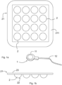
- figures 1a and 1b illustrate a preferred embodiment of the system according to the present invention.
- the system comprises at least one electrode 1 for transmitting the detected signal and conduction means of the signal interposed between the electrode 1 and the scalp of a patient, as well as fixation means of the electrode to the scalp.
- the fixation means and the conduction means are constituted by a single drop/tablet element 2, made with a material of the hydrogel type.
- Figure 1a shows a plurality of drop/tablet elements 2, while showing a single electrode 1.
- system which is the object of the present invention can provide any number of electrodes 1 and any number of drop/tablet elements 2.
- the electrode 1 is advantageously constituted by a cup electrode and has a cup end 11 and a signal transmission cable 12.
- the cup unit 11 is adapted to be positioned on the skull of the patient, while the transmission cable 12 is responsible for the transmission of the detected signal to a processing unit, including inside electrocardiographs known in the state of the art.
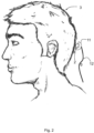
- the cup end 11 constitutes a housing seat for the drop/tablet element 2, as illustrated in Figure 2 .
- Figure 2 shows a patient 3 and a section of the electrode 1 in combination with the drop/tablet element 2.
- the cup end 11 houses in its interior the drop/tablet element 2.
- the cross-section of the drop/tablet element 2 of Figure 2 corresponds to an ellipse, however, being constituted by a hydrogel, the drop/tablet element 2 is deformed in such a way as to adhere to the inner surface of the cup end 11 and to the scalp of the patient 3.
- This deformation allows to create a seamless contact between the scalp of the patient 3 and the cup end 11 of the electrode 1.
- the drop/tablet element 2 has dimensions such as to be housed inside the cup end 11, without that the excessive deformation of the drop/tablet element 2 causes an excessive spillage of hydrogel from the edges of the cup ends 11.
- the dimensions of the drop/tablet element 2 are such as to allow it to be housed inside the cup end 11 and cover the edges facing toward the scalp.
- the drop/tablet element 2 In the condition of the positioning of the electrode 1, the drop/tablet element 2 therefore deforms its surfaces so as to create surfaces complementary to the scalp of the patient 3 and at the cup end 11.
- Such retention means are preferably constituted by an adhesive support, which can be positioned on the outer surface of the cup end 11 and with its ends fixed to the scalp of the patient 3.
- the system further comprises a plate-like support element 21 on which to place the plurality of drop/tablet elements 2.
- the drop/tablet element 2 are none other than drops of hydrogel arranged on the upper surface of the plate-like element 21, made in the form of a sheet, preferably of plastic material, on which the drop/tablet elements 2 remain fixed thanks to their adhesive feature, until they are removed to be used in combination with the electrodes 1.
- the plate-like support element can be constituted by a simple sheet of plastic material on which drop/tablet elements 2 can be arranged.
- the plate-like element is constituted by a blister pack-type element 21 that presents housing seats 22 of the drop/tablet element 2.
- the drop/tablet element 2 are deposited inside the housing seats 22, after which the blister pack 21 is closed by a protective plastic film 23.
- the protective plastic film 23 is attached to the blister pack 21 in such a way that, once removed, the drop/tablet elements 2 remain inside the housing seats 22.
- the blister packs 21 is constituted by a flat plate-like element without housing seats, on which the individual drop/tablet element are arranged.
- the deposition of the hydrogel drop/tablet element 2 within the housing seats 22 confers to the elements a semicircle shape, adapted to be housed inside the cup end 11 of the electrode 1.
- a disposable electrode preferably a cup electrode, in which there is a drop/tablet element 2 inserted inside the cup end 11.
- the cup end 11 can for example be sealed through the use of a protective film in a manner quite similar to the protective film 23 described previously, in this case fixed to the edges of the cup end 11.
- the blister pack 21 may have a square shape, with side equal to 140 millimetres.
- the housing seats 22, constituted by semicircular elements, have a diameter comprised between 20 and 22 millimetres and are mutually spaced by a measure between 3 and 5 millimetres.
- the method object of the present invention involves the fixation of at least one electrode to the scalp of a patient for the transmission of the detected electrical signals.
- the method object of the present invention includes the following steps:
- the tablet element 2 performs the dual function of gluing of the electrode and conducting the signal.
- the method object of the present invention can be preferably used with a plurality of electrodes, in order to place them on a wide surface of the skull of the patient to obtain the tracking of the EEG signal.
- the fixation of the electrode includes the following steps:
- the step indicated with 42 is preferably provided in combination with the use of the cup electrode 1.
- the drop/tablet elements 2 are fixed to the plate-like element 21 in a stable manner.
- the operator When an operator must secure the electrode 1 to the scalp of a patient, thanks to the peculiar shape of the cup electrode 1, the operator will not have to handle the drop/tablet element 2, but it will be sufficient to use the cup end 11 as a spoon to remove the drop/tablet element 2 from the plate-like element or from the blister pack 21 and insert it to make contact with the inner surface of the cup end 11.
- the operator positions the electrode 1 in the region of interest of the skull of the patient 3 and with a slight pressure, which causes the deformation of the drop/tablet element 2, glues the electrode 1 to the scalp of the patient 3.
- the step 43 may provide a further fixation of the electrode 1 to the scalp of the patient 3, through the use of adhesive support, as previously described.
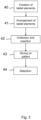
- Figure 3 illustrates a possible embodiment which provides a method of use of the system object of the present invention and a method for the creation of the system object of the present invention.
- the method of use is the one just described, in which an operator uses the packaged element constituted by the drop/tablet elements, inserted inside the blister packs of Figure 1b , places the drop/tablet elements on the electrode and carries out the examination.
- This "operator-side" methodology may be provided in combination with the method for the creation of the fixation and conduction means belonging to the system object of the present invention.
- this method includes the following steps:
- the steps from 40 to 44 may be provided in combination, or it is possible to provide that the steps 40 and 41 are performed by a producer of hydrogel or the like, while steps 42 to 44 can be performed by the users, i.e. by operators who intend to perform EEG signal detection analysis.
Landscapes
- Life Sciences & Earth Sciences (AREA)
- Health & Medical Sciences (AREA)
- Medical Informatics (AREA)
- Animal Behavior & Ethology (AREA)
- Pathology (AREA)
- Engineering & Computer Science (AREA)
- Biomedical Technology (AREA)
- Heart & Thoracic Surgery (AREA)
- Physics & Mathematics (AREA)
- Molecular Biology (AREA)
- Surgery (AREA)
- Biophysics (AREA)
- General Health & Medical Sciences (AREA)
- Public Health (AREA)
- Veterinary Medicine (AREA)
- Electrotherapy Devices (AREA)
- Investigating Or Analysing Materials By The Use Of Chemical Reactions (AREA)
- Glass Compositions (AREA)
- Measurement And Recording Of Electrical Phenomena And Electrical Characteristics Of The Living Body (AREA)
Description
- The present invention relates to a system for detecting electroencephalographic signals comprising at least one electrode for transmission of the detected signal, conduction means of said signal interposed between the electrode and the scalp of a patient and fixation means of said electrode to the scalp.
- What was just described is the common configuration of systems commonly used for the detection and recording of the electroencephalographic signals (EEG).
- The recording of EEG signals is a non-invasive practice, involves the positioning of one or more electrodes in contact with the scalp of a patient through an electrolyte, for transmitting the signal to a processing unit.
- The signal is detected by the electrode thanks to the presence of a layer of conductive gel interposed between the electrode and the scalp.
- In view of the nature of the detected signal, it is evident that a correct registration and subsequent processing of EEG signals require a firm positioning of the electrode so as to provide the processing unit with accurate data to avoid the generation of artifacts, or inaccurate readings that generate an incorrect analysis.
- To ensure a correct positioning of the electrode, the systems known in the state of the art use glues, creams, etc. which give a firm fixation in the desired position.
- One of the major disadvantages in the use of these glues, creams, etc. is related to the cleaning of the scalp of the patient after their use: in fact, the removal of glues, creams, etc. is not particularly effortless, easy and atraumatic and requires a careful cleaning.
- In systems known in the state of the art, the cleaning procedure on the scalp is necessarily carried out with detergent materials and/or solvents, not always suited to the scalp.
- In fact, the used solvents must be particularly aggressive in order to obtain a satisfactory cleaning the scalp which allows the removal of the used glues and creams.
- These effects are particularly troublesome for the patient if, as happens in common practice, the recording of EEG signals requires the use of numerous electrodes, arranged along the entire surface of the skull of the patient.
- Therefore, in systems known in the state of the art, the procedure for cleaning and removing the electrodes has no negative aspects which are just related to the harshness of the used solvents, but also disadvantages in terms of timing.
- These disadvantages are found not only in the cleaning process but also in the part preceding the examination and preparation of the patient, i.e. the positioning of the electrodes.
- In fact the use of conductive gel in combination with glues for the positioning of the electrodes requires a long duration positioning procedure.
- Some systems known in the state of the art seek to avoid the use of glues through the positioning of the electrodes supported by elastic material.
- However, these electrodes require, in addition to the use of elastic caps that cover the skull of the patient, in order to fix the electrode in position, also the use of liquid gel for the contact with the scalp and the creation of the registration interface.
- It is evident that this solution, in addition to increasing the structural complexity of the whole system, requires the availability of owning a range of different sizes of caps that can cover as much as possible the different patients and set-up requires a particularly long configuration time of the entire system.
- Therefore, there is a need, not satisfied by the systems known in the state of the art, to provide a detection system of EEG signals which overcomes the disadvantages described above, ensuring a simple and functional positioning of the electrodes.
KR 101 037 405 B1 GB 1 299 449 A - The present invention, defined by a system according to
claim 1, a method according to claim 5 and a method according to claim 7 (with further embodiments found in the respective dependent claims 2-4, 6), achieves the above objects by providing a system as described above, in which the conduction means and the fixation means are constituted by a single hydrogel layer. - A particularly dense, nearly solid polymer is made, and has both conductive and adhesive features, so as to speed up the electrode positioning process, using a single component.
- The hydrogel may for example be provided in the form of a drop/tablet contained in a dispenser/blister pack capable of allowing a user to use and position the hydrogel on the scalp of the patient in points of interest through the use of a cup electrode.
- According to the invention, the hydrogel material is provided in the form of a drop/tablet element.
- According to this configuration, the hydrogel is therefore pre-dosed, i.e. provided in predetermined doses, sufficient to conduct the signal and to ensure a sufficiently wide surface for gluing.
- The particularly dense nature of the hydrogel allows to create finite elements that can be taken one by one to be positioned and removed easily from the scalp of the patient.
- It is specified that some embodiments illustrated in the following will describe a specific embodiment of the shape of the drop/tablet element.
- The removal of these drop/tablet element leaves minimal residue on the hair of the patient, easily removable with aqueous solutions, not harmful to the scalp of the patient.
- The shape of the drop/tablet element also has a specific advantage, i.e. to provide a sort of bearing interposed between the scalp and the electrode, preventing the trauma due to the pressure of the electrode on the scalp, effect known with the name of "skin-breakdown".
- For this reason, the hydrogel that constitutes the drop/tablet element must have a density such as to be sufficiently rigid for the creation of finite elements, but at the same time sufficiently soft, i.e. mechanically yielding, to change its surfaces so as to adapt them to the contact surfaces of the skull of the patient and/or the electrode, once the drop/tablet element is used for the detection of the signals.
- Moreover, the hydrogel that constitutes the drop/tablet element also has both conductive and adhesive features with respect to the skull of the patient.
- The system object of the present invention can involve any type of cup electrode known in the state of the art, which has a surface facing the scalp adapted to house said drop/tablet element.
- The shape of the drop/tablet element is particularly advantageous in combination with the cup electrodes, especially if the drop/tablet element has a size such as to be housed inside the electrode cup.
- This configuration has advantageous effects also on the positioning of the electrodes: the cup electrode can be used by a user in a similar manner to a spoon, which collects the drop/tablet element to then be immediately placed on the scalp of the patient.
- The above mentioned advantages are particularly relevant in the case in which a plurality of electrodes and a plurality of drop/tablet elements are provided.
- Moreover in order to facilitate the collection of such drop/tablet elements by the cup electrodes, it is according to the invention to group all the drop/tablet element through a single support element, being a plate-like support element, on which the drop/tablet elements are placed.
- The hydrogel elements remain attached to the upper surface of the plate-like element and can be removed from the electrode cup, to ensure their positioning on the scalp of the patient.
- Since the electrode has a wire for the connection of the processing unit, in order to prevent accidental tractions of the operator with the wire from moving the electrode, an embodiment variant of the system according to the present invention provides retention means for retaining the electrode in position.
- For example, such retention means can be constituted by an adhesive support, placed in contact with the scalp of the patient and the outer surface of the head of the electrode.
- In addition, in the light of the features described above, the present disclosure relates to an example by itself not covered by the claims of a disposable electrode for detecting electroencephalographic signals that comprises a cup electrode and a hydrogel drop/tablet element inserted inside the cup of said electrode.
- It is therefore possible to provide a single pack of a disposable electrode already ready to be positioned on the scalp of a patient.
- As for the embodiment variants described above, also in this case it is possible to provide an adhesive support for retaining the electrode in position on the scalp of the patient.
- In the light of the advantageous features described heretofore, the present invention also relates to a method for the detection of electroencephalographic signals.
- This method provides for the use of the system or of the electrode described above and in comprises the fixation of at least one electrode to the scalp of a patient for the transmission of the detected electrical signals.
- According to the method object of the present invention, the fixation of the electrode includes the following steps:
- a) positioning a drop/tablet element in contact with the electrode,
- b) bonding of the electrode to the scalp of the patient through the drop/tablet element,
- c) detection of electroencephalographic signals through the drop/tablet element.
- Also in this case, the drop/tablet element allows the use of a single component that allows at the same time the conduction of EEG signals, as well as the gluing of the electrode to the head of the patient.
- The application of the electrode is therefore immediate, fast, efficient and particularly "clean".
- In combination with this embodiment, preferably the step of positioning of the drop/tablet element in contact with the electrode, provides for the collection of the drop/tablet element from the plate-like element and the insertion on said electrode, the electrode consisting of a cup electrode.
- To improve the retention in position of the electrode, the step of gluing of the electrode provides a step of retaining the position of said electrode to the scalp of the patient through the use of a preformed adhesive support.
- In conclusion, an object of the present invention is a method for creating the conduction and fixation means of the system described above according to claim 7.
- Finally, it is specified that a further example by itself not covered by the claims also relates to a collection of hydrogel elements.
- This collection includes hydrogel drop/tablet elements created according to one or more of the features described above and which are arranged on a plate-like element, in a similar manner to as some types of tablets or pills are inserted inside pharmaceutical blister packs, as will be illustrated later.
- These and other features and advantages of the present invention will become clearer from the following description of some exemplary embodiments illustrated in the attached drawings in which:
-
Figures 1a and 1b show two views of the system object of the present invention according to a possible embodiment; -
Figure 2 shows a sectional view of a tablet element coupled to an electrode belonging to the system object of the present invention; -
Figure 3 is a block diagram showing the principle of the method object of the present invention. - It is specified that the figures attached to the present patent application illustrate some embodiments of the system and the method object of the present invention, in order to better understand its advantages and the described features.
- These embodiments are therefore to be understood as purely illustrative and do not limit the scope of the inventive concept of the present invention, i.e. creating a system for detecting electroencephalographic signals that involves the fixation of at least one electrode to the scalp of a patient through a single layer of hydrogel, which guarantees both the gluing to the scalp and the transmission of electrical signals from the scalp to the electrode.
- In particular,
figures 1a and 1b illustrate a preferred embodiment of the system according to the present invention. - According to this embodiment, the system comprises at least one
electrode 1 for transmitting the detected signal and conduction means of the signal interposed between theelectrode 1 and the scalp of a patient, as well as fixation means of the electrode to the scalp. - In the variant illustrated in
Figures 1a and 1b , the fixation means and the conduction means are constituted by a single drop/tablet element 2, made with a material of the hydrogel type. -
Figure 1a shows a plurality of drop/tablet elements 2, while showing asingle electrode 1. - It is evident that the system which is the object of the present invention can provide any number of
electrodes 1 and any number of drop/tablet elements 2. - The
electrode 1 is advantageously constituted by a cup electrode and has acup end 11 and asignal transmission cable 12. - The
cup unit 11 is adapted to be positioned on the skull of the patient, while thetransmission cable 12 is responsible for the transmission of the detected signal to a processing unit, including inside electrocardiographs known in the state of the art. - The
cup end 11 constitutes a housing seat for the drop/tablet element 2, as illustrated inFigure 2 . -
Figure 2 shows apatient 3 and a section of theelectrode 1 in combination with the drop/tablet element 2. - The cup end 11 houses in its interior the drop/
tablet element 2. - For simplicity of illustration, the cross-section of the drop/
tablet element 2 ofFigure 2 corresponds to an ellipse, however, being constituted by a hydrogel, the drop/tablet element 2 is deformed in such a way as to adhere to the inner surface of thecup end 11 and to the scalp of thepatient 3. - This deformation allows to create a seamless contact between the scalp of the
patient 3 and thecup end 11 of theelectrode 1. - Advantageously, the drop/
tablet element 2 has dimensions such as to be housed inside thecup end 11, without that the excessive deformation of the drop/tablet element 2 causes an excessive spillage of hydrogel from the edges of the cup ends 11. - Advantageously, the dimensions of the drop/
tablet element 2 are such as to allow it to be housed inside thecup end 11 and cover the edges facing toward the scalp. - In the condition of the positioning of the
electrode 1, the drop/tablet element 2 therefore deforms its surfaces so as to create surfaces complementary to the scalp of thepatient 3 and at thecup end 11. - According to a further embodiment, it is possible to provide retention means for retaining the
electrode 1 in position, not shown inFigure 2 , to assist the gluing action performed by the hydrogel of theelectrode 1 to the scalp of thepatient 3. - Such retention means are preferably constituted by an adhesive support, which can be positioned on the outer surface of the
cup end 11 and with its ends fixed to the scalp of thepatient 3. - According to the variant illustrated in
Figures 1a and 1b , the system further comprises a plate-like support element 21 on which to place the plurality of drop/tablet elements 2. - The drop/
tablet element 2 are none other than drops of hydrogel arranged on the upper surface of the plate-like element 21, made in the form of a sheet, preferably of plastic material, on which the drop/tablet elements 2 remain fixed thanks to their adhesive feature, until they are removed to be used in combination with theelectrodes 1. - It is evident that the plate-like support element can be constituted by a simple sheet of plastic material on which drop/
tablet elements 2 can be arranged. - According to the variant illustrated in
Figures 1a and 1b , the plate-like element is constituted by a blister pack-type element 21 that presentshousing seats 22 of the drop/tablet element 2. - The drop/
tablet element 2 are deposited inside thehousing seats 22, after which theblister pack 21 is closed by aprotective plastic film 23. - The
protective plastic film 23 is attached to theblister pack 21 in such a way that, once removed, the drop/tablet elements 2 remain inside thehousing seats 22. - For example it is possible to provide a
zone 211 in which theprotective film 23 may be glued or heat-welded to theblister pack 21. - In alternative, it is possible to envisage that the blister packs 21 is constituted by a flat plate-like element without housing seats, on which the individual drop/tablet element are arranged.
- The deposition of the hydrogel drop/
tablet element 2 within thehousing seats 22 confers to the elements a semicircle shape, adapted to be housed inside thecup end 11 of theelectrode 1. - In a similar manner it is possible to provide a disposable electrode, preferably a cup electrode, in which there is a drop/
tablet element 2 inserted inside thecup end 11. - The
cup end 11 can for example be sealed through the use of a protective film in a manner quite similar to theprotective film 23 described previously, in this case fixed to the edges of thecup end 11. - With particular reference to
Figures 1a and 1b , theblister pack 21 may have a square shape, with side equal to 140 millimetres. - The
housing seats 22, constituted by semicircular elements, have a diameter comprised between 20 and 22 millimetres and are mutually spaced by a measure between 3 and 5 millimetres. - The system just described may be used to perform the method for detecting electroencephalographic signals object of the present invention, referred to a possible embodiment is illustrated in
Figure 3 through a flow chart. - As in the methods known to the state of the art, the method object of the present invention involves the fixation of at least one electrode to the scalp of a patient for the transmission of the detected electrical signals.
- From a general point of view, the method object of the present invention includes the following steps:
- a) positioning a drop/tablet element in contact with the electrode,
- b) bonding of the electrode to the scalp of the patient through the drop/tablet element,
- c) detection of electroencephalographic signals through the drop/tablet element.
- As anticipated, the
tablet element 2 performs the dual function of gluing of the electrode and conducting the signal. - According to the variant shown in
Figure 3 , and on the basis of the system ofFigures 1a, 1b and2 , the method object of the present invention can be preferably used with a plurality of electrodes, in order to place them on a wide surface of the skull of the patient to obtain the tracking of the EEG signal. - In particular, the fixation of the electrode includes the following steps:
- collection and insertion of each drop/tablet element on a
corresponding electrode 1,step 42, - gluing of the
electrode 1 to the scalp of thepatient 3,step 43, - detection of the signal, indicated with 44.
- The step indicated with 42 is preferably provided in combination with the use of the
cup electrode 1. - Thanks to the fact they are made of adhesive hydrogel, the drop/
tablet elements 2 are fixed to the plate-like element 21 in a stable manner. - When an operator must secure the
electrode 1 to the scalp of a patient, thanks to the peculiar shape of thecup electrode 1, the operator will not have to handle the drop/tablet element 2, but it will be sufficient to use thecup end 11 as a spoon to remove the drop/tablet element 2 from the plate-like element or from theblister pack 21 and insert it to make contact with the inner surface of thecup end 11. - Once the coupling between the
tablet element 2 and theelectrode 1 is obtained, the operator positions theelectrode 1 in the region of interest of the skull of thepatient 3 and with a slight pressure, which causes the deformation of the drop/tablet element 2, glues theelectrode 1 to the scalp of thepatient 3. - At this point it is possible to detect the electroencephalographic signals to perform the examination of interest.
- As is known in the state of the art, it is possible to provide at the beginning of the method, a step relative to the preparation of the skin of the patient, such as for example cleaning of the area concerned to the positioning of the electrode.
- Finally, it is specified that the
step 43 may provide a further fixation of theelectrode 1 to the scalp of thepatient 3, through the use of adhesive support, as previously described. - In particular,
Figure 3 illustrates a possible embodiment which provides a method of use of the system object of the present invention and a method for the creation of the system object of the present invention. - The method of use is the one just described, in which an operator uses the packaged element constituted by the drop/tablet elements, inserted inside the blister packs of
Figure 1b , places the drop/tablet elements on the electrode and carries out the examination. - This "operator-side" methodology, defined by
steps 42 to 44, may be provided in combination with the method for the creation of the fixation and conduction means belonging to the system object of the present invention. - With reference to
Figure 3 , this method includes the following steps: - creation of a plurality of hydrogel drop/
tablet elements 2, indicated with 40, - arrangement of the drop/
tablet elements 2 on a plate-like support element, or inside thehousing seats 22 of theblister pack 21, indicated with 41. - The steps from 40 to 44 may be provided in combination, or it is possible to provide that the
steps steps 42 to 44 can be performed by the users, i.e. by operators who intend to perform EEG signal detection analysis. - While the invention can be changed according to different modifications and alternative constructions, some preferred embodiments were shown in the drawings and described in detail.
- It should be understood, however, that there is no intention of limiting the invention to the specific illustrated embodiment but, on the contrary, it aims at covering all modifications, alternative constructions, and equivalents falling within the scope of the invention as defined in the claims.
- The use of "for example", "etc.", "or" refers to non-exclusive non-limiting alternatives, unless otherwise stated.
- The use of "includes" means "includes but not limited to", unless otherwise stated.
Claims (7)
- System for detecting electroencephalographic signals comprising at least one electrode (1) for the transmission of the detected signal, conduction means of said signal configured to be interposed between the electrode (1) and the scalp of a patient (3) and fixation means of said electrode (1) to the scalp,said conduction means and said fixation means being constituted by a single layer of hydrogel,said single layer of hydrogel is constituted by a finite element in the form of a drop or tablet element (2), provided in predetermined doses sufficient to conduct the signal and to ensure a sufficient wide surface for gluing, the particularly dense nature of the hydrogel allowing to create finite elements configured to be positioned and to be easily removed from the scalp of the patient the drop or tablet element (2) having a density such as to be sufficiently rigid for the creation of finite elements and at the same time sufficiently soft, i.e. mechanically yielding, to change its surfaces so as to adapt them to the contact surfaces of the skull of the patient and/or of the electrode,the drop or tablet elements (2) being arranged as drops of hydrogel on the upper surface of a plate-like element, made in the form of a sheet, on which the drop or tablet elements (2) remain fixed thanks to their adhesive feature, until they are removed to be used in combination with the electrodes,wherein said electrode is a cup electrode.
- System according to claim 1, wherein said drop or tablet element (2) has a size such as to be housed on the electrode surface facing toward the scalp.
- System according to one or more of the preceding claims, wherein retention means are provided for retaining the electrode (1) in position on the scalp of the patient (3).
- System according to claim 3, wherein said retention means consist of an adhesive support.
- Method for detecting encephalographic signals which involves the use of the system according to one or more of claims 1 to 4, which method comprises the fixation of the at least one electrode (1) to the scalp of a patient (3) for the transmission of the detected electrical signals, wherein said fixation involves the following steps:a) positioning the drop or tablet element (2) in contact with said electrode (1),b) bonding said electrode (1) to the scalp of the patient (3) through said drop or tablet element (2),c) detection of the electroencephalographic signals through said drop or tablet element (2).
- Method according to claim 5, wherein step b) includes a step of retaining said electrodes (1) in position on the scalp of the patient (3) through the use of an adhesive support.
- Method for the creation of the conduction and fixation means of the system according to claims 1 to 4, wherein the method involves the following steps:- creation of the plurality of hydrogel drop or tablet elements (2) according to claim 1,- arrangement of said plurality of drop or tablet elements (2) as drops of hydrogel on the upper surface of the plate-like element (21 according to claim 1.
Applications Claiming Priority (1)
| Application Number | Priority Date | Filing Date | Title |
|---|---|---|---|
| IT102018000004455A IT201800004455A1 (en) | 2018-04-12 | 2018-04-12 | Detection system of electroencephalographic signals |
Publications (3)
| Publication Number | Publication Date |
|---|---|
| EP3552541A1 EP3552541A1 (en) | 2019-10-16 |
| EP3552541C0 EP3552541C0 (en) | 2025-01-29 |
| EP3552541B1 true EP3552541B1 (en) | 2025-01-29 |
Family
ID=62875139
Family Applications (1)
| Application Number | Title | Priority Date | Filing Date |
|---|---|---|---|
| EP19168794.6A Active EP3552541B1 (en) | 2018-04-12 | 2019-04-11 | System for the detection of electroencephalographic signals |
Country Status (3)
| Country | Link |
|---|---|
| US (1) | US20190313932A1 (en) |
| EP (1) | EP3552541B1 (en) |
| IT (1) | IT201800004455A1 (en) |
Citations (7)
| Publication number | Priority date | Publication date | Assignee | Title |
|---|---|---|---|---|
| GB1299449A (en) * | 1968-12-18 | 1972-12-13 | Minnesota Mining & Mfg | Conductive gel pads |
| US5540033A (en) * | 1994-01-10 | 1996-07-30 | Cambrex Hydrogels | Integrated Manufacturing process for hydrogels |
| US5800685A (en) * | 1996-10-28 | 1998-09-01 | Cardiotronics Systems, Inc. | Electrically conductive adhesive hydrogels |
| US20070106170A1 (en) * | 2005-11-10 | 2007-05-10 | Conopco, Inc., D/B/A Unilever | Apparatus and method for acquiring a signal |
| KR101037405B1 (en) * | 2010-08-23 | 2011-05-30 | 박익로 | Biomedical Electrode with Dropper |
| US20130131746A1 (en) * | 2009-03-20 | 2013-05-23 | ElectroCore, LLC. | Non-invasive vagus nerve stimulation devices and methods to treat or avert atrial fibrillation |
| US11375952B2 (en) * | 2017-10-05 | 2022-07-05 | Sekisui Plastics Co., Ltd. | Adhesive hydrogel and medical electrode using the same |
Family Cites Families (4)
| Publication number | Priority date | Publication date | Assignee | Title |
|---|---|---|---|---|
| US20090105576A1 (en) * | 2007-10-22 | 2009-04-23 | Nam Hoai Do | Electrode conductive element |
| US10130278B2 (en) * | 2012-10-15 | 2018-11-20 | Jordan Neuroscience, Inc. | Wireless EEG unit |
| FI126093B (en) * | 2012-11-12 | 2016-06-30 | Mega Elektroniikka Oy | Arrangement and method for conducting electrode measurements |
| EP3236842A4 (en) * | 2015-02-09 | 2017-11-29 | Vios Medical Singapore Pte Ltd | Patient worn sensor assembly |
-
2018
- 2018-04-12 IT IT102018000004455A patent/IT201800004455A1/en unknown
-
2019
- 2019-04-10 US US16/380,290 patent/US20190313932A1/en active Pending
- 2019-04-11 EP EP19168794.6A patent/EP3552541B1/en active Active
Patent Citations (9)
| Publication number | Priority date | Publication date | Assignee | Title |
|---|---|---|---|---|
| GB1299449A (en) * | 1968-12-18 | 1972-12-13 | Minnesota Mining & Mfg | Conductive gel pads |
| US5540033A (en) * | 1994-01-10 | 1996-07-30 | Cambrex Hydrogels | Integrated Manufacturing process for hydrogels |
| US5800685A (en) * | 1996-10-28 | 1998-09-01 | Cardiotronics Systems, Inc. | Electrically conductive adhesive hydrogels |
| EP0934593B1 (en) * | 1996-10-28 | 2006-06-14 | Ballard Medical Products | Electrically conductive adhesive hydrogels |
| US20070106170A1 (en) * | 2005-11-10 | 2007-05-10 | Conopco, Inc., D/B/A Unilever | Apparatus and method for acquiring a signal |
| US20130131746A1 (en) * | 2009-03-20 | 2013-05-23 | ElectroCore, LLC. | Non-invasive vagus nerve stimulation devices and methods to treat or avert atrial fibrillation |
| KR101037405B1 (en) * | 2010-08-23 | 2011-05-30 | 박익로 | Biomedical Electrode with Dropper |
| WO2012026638A1 (en) * | 2010-08-23 | 2012-03-01 | Park Ik Ro | Biomedical electrode having spuit |
| US11375952B2 (en) * | 2017-10-05 | 2022-07-05 | Sekisui Plastics Co., Ltd. | Adhesive hydrogel and medical electrode using the same |
Non-Patent Citations (2)
| Title |
|---|
| NEUMAN M R ED - BRONZINO JOSEPH D: "Chapter 48: Biopotential Electrodes", 1 January 2000, THE BIOMEDICAL ENGINEERING HANDBOOK; [THE ELECTRICAL ENGINEERING HANDBOOK SERIES], BOCA RATON, FLA. [U.A.] : CRC PRESS [U.A.], US, PAGE(S) 1 - 12, ISBN: 978-3-540-66351-5, XP002566008 * |
| NIKULIN V V ET AL: "Miniaturized electroencephalographic scalp electrode for optimal wearing comfort", CLINICAL NEUROPHYSIOLOGY, ELSEVIER, AMSTERDAM, NL, vol. 121, no. 7, 1 July 2010 (2010-07-01), pages 1007 - 1014, XP027064564, ISSN: 1388-2457, [retrieved on 20100315], DOI: 10.1016/J.CLINPH.2010.02.008 * |
Also Published As
| Publication number | Publication date |
|---|---|
| US20190313932A1 (en) | 2019-10-17 |
| EP3552541C0 (en) | 2025-01-29 |
| EP3552541A1 (en) | 2019-10-16 |
| IT201800004455A1 (en) | 2019-10-12 |
Similar Documents
| Publication | Publication Date | Title |
|---|---|---|
| US8238998B2 (en) | Tab electrode | |
| CN106470602B (en) | medical electrodes | |
| JP4643768B2 (en) | In vivo component measurement system, tissue fluid collection device, and in vivo component measurement method | |
| EP3331443B1 (en) | Biological fluid collection device | |
| US20050021066A1 (en) | Analytical device with lancet and test element | |
| CN110381825B (en) | Adhesive extender for medical electrodes and use thereof with wearable monitors | |
| EP3829438A1 (en) | Bi-rigidity adhesive patch | |
| EP3165173B1 (en) | Splittable fluid sample collector | |
| WO2009055455A2 (en) | Electrode conductive element | |
| CN116323905B (en) | Sample collection stick | |
| CN116157505B (en) | Sample collection stick | |
| EP3552541A1 (en) | System for the detection of electroencephalographic signals | |
| US20180214125A1 (en) | Ultrasound Gel Module Assemblies | |
| EP3011900A1 (en) | Electrode module, suction system and tool for biopotential monitoring | |
| JP5710505B2 (en) | Eye specimen collection device | |
| JP3169659U (en) | Body fluid collection device | |
| JP5930688B2 (en) | Lancet cartridge | |
| JP6670031B2 (en) | Method for applying adhesive and toilet bowl device | |
| KR101444281B1 (en) | Glucose measuring strip with separable lancet | |
| US9005137B2 (en) | Device for collecting a urine sample | |
| KR20160066075A (en) | Sensor for measuring biological signal | |
| JP6090826B2 (en) | Eyelid pressure sensor | |
| CN218673917U (en) | Disposable ear thermometer ejection support | |
| US9675284B2 (en) | Apparatus and method for detecting and\or monitoring one or more compounds in blood | |
| JP5778763B2 (en) | Ear coupler and hearing test system |
Legal Events
| Date | Code | Title | Description |
|---|---|---|---|
| PUAI | Public reference made under article 153(3) epc to a published international application that has entered the european phase |
Free format text: ORIGINAL CODE: 0009012 |
|
| STAA | Information on the status of an ep patent application or granted ep patent |
Free format text: STATUS: THE APPLICATION HAS BEEN PUBLISHED |
|
| AK | Designated contracting states |
Kind code of ref document: A1 Designated state(s): AL AT BE BG CH CY CZ DE DK EE ES FI FR GB GR HR HU IE IS IT LI LT LU LV MC MK MT NL NO PL PT RO RS SE SI SK SM TR |
|
| AX | Request for extension of the european patent |
Extension state: BA ME |
|
| STAA | Information on the status of an ep patent application or granted ep patent |
Free format text: STATUS: REQUEST FOR EXAMINATION WAS MADE |
|
| 17P | Request for examination filed |
Effective date: 20200417 |
|
| RBV | Designated contracting states (corrected) |
Designated state(s): AL AT BE BG CH CY CZ DE DK EE ES FI FR GB GR HR HU IE IS IT LI LT LU LV MC MK MT NL NO PL PT RO RS SE SI SK SM TR |
|
| STAA | Information on the status of an ep patent application or granted ep patent |
Free format text: STATUS: EXAMINATION IS IN PROGRESS |
|
| 17Q | First examination report despatched |
Effective date: 20230616 |
|
| RIC1 | Information provided on ipc code assigned before grant |
Ipc: A61B 5/291 20210101ALI20240703BHEP Ipc: A61B 5/00 20060101AFI20240703BHEP |
|
| GRAP | Despatch of communication of intention to grant a patent |
Free format text: ORIGINAL CODE: EPIDOSNIGR1 |
|
| STAA | Information on the status of an ep patent application or granted ep patent |
Free format text: STATUS: GRANT OF PATENT IS INTENDED |
|
| INTG | Intention to grant announced |
Effective date: 20240911 |
|
| RAP3 | Party data changed (applicant data changed or rights of an application transferred) |
Owner name: SPES MEDICA S.P.A. |
|
| GRAS | Grant fee paid |
Free format text: ORIGINAL CODE: EPIDOSNIGR3 |
|
| GRAA | (expected) grant |
Free format text: ORIGINAL CODE: 0009210 |
|
| STAA | Information on the status of an ep patent application or granted ep patent |
Free format text: STATUS: THE PATENT HAS BEEN GRANTED |
|
| AK | Designated contracting states |
Kind code of ref document: B1 Designated state(s): AL AT BE BG CH CY CZ DE DK EE ES FI FR GB GR HR HU IE IS IT LI LT LU LV MC MK MT NL NO PL PT RO RS SE SI SK SM TR |
|
| REG | Reference to a national code |
Ref country code: GB Ref legal event code: FG4D |
|
| REG | Reference to a national code |
Ref country code: CH Ref legal event code: EP |
|
| REG | Reference to a national code |
Ref country code: DE Ref legal event code: R096 Ref document number: 602019065323 Country of ref document: DE |
|
| REG | Reference to a national code |
Ref country code: IE Ref legal event code: FG4D |
|
| U01 | Request for unitary effect filed |
Effective date: 20250226 |
|
| U07 | Unitary effect registered |
Designated state(s): AT BE BG DE DK EE FI FR IT LT LU LV MT NL PT RO SE SI Effective date: 20250305 |
|
| U20 | Renewal fee for the european patent with unitary effect paid |
Year of fee payment: 7 Effective date: 20250428 |
|
| PG25 | Lapsed in a contracting state [announced via postgrant information from national office to epo] |
Ref country code: RS Free format text: LAPSE BECAUSE OF FAILURE TO SUBMIT A TRANSLATION OF THE DESCRIPTION OR TO PAY THE FEE WITHIN THE PRESCRIBED TIME-LIMIT Effective date: 20250429 |
|
| PG25 | Lapsed in a contracting state [announced via postgrant information from national office to epo] |
Ref country code: PL Free format text: LAPSE BECAUSE OF FAILURE TO SUBMIT A TRANSLATION OF THE DESCRIPTION OR TO PAY THE FEE WITHIN THE PRESCRIBED TIME-LIMIT Effective date: 20250129 |
|
| PG25 | Lapsed in a contracting state [announced via postgrant information from national office to epo] |
Ref country code: ES Free format text: LAPSE BECAUSE OF FAILURE TO SUBMIT A TRANSLATION OF THE DESCRIPTION OR TO PAY THE FEE WITHIN THE PRESCRIBED TIME-LIMIT Effective date: 20250129 |
|
| PG25 | Lapsed in a contracting state [announced via postgrant information from national office to epo] |
Ref country code: IS Free format text: LAPSE BECAUSE OF FAILURE TO SUBMIT A TRANSLATION OF THE DESCRIPTION OR TO PAY THE FEE WITHIN THE PRESCRIBED TIME-LIMIT Effective date: 20250529 Ref country code: NO Free format text: LAPSE BECAUSE OF FAILURE TO SUBMIT A TRANSLATION OF THE DESCRIPTION OR TO PAY THE FEE WITHIN THE PRESCRIBED TIME-LIMIT Effective date: 20250429 |
|
| PG25 | Lapsed in a contracting state [announced via postgrant information from national office to epo] |
Ref country code: HR Free format text: LAPSE BECAUSE OF FAILURE TO SUBMIT A TRANSLATION OF THE DESCRIPTION OR TO PAY THE FEE WITHIN THE PRESCRIBED TIME-LIMIT Effective date: 20250129 |
|
| PG25 | Lapsed in a contracting state [announced via postgrant information from national office to epo] |
Ref country code: GR Free format text: LAPSE BECAUSE OF FAILURE TO SUBMIT A TRANSLATION OF THE DESCRIPTION OR TO PAY THE FEE WITHIN THE PRESCRIBED TIME-LIMIT Effective date: 20250430 |
|
| PG25 | Lapsed in a contracting state [announced via postgrant information from national office to epo] |
Ref country code: SM Free format text: LAPSE BECAUSE OF FAILURE TO SUBMIT A TRANSLATION OF THE DESCRIPTION OR TO PAY THE FEE WITHIN THE PRESCRIBED TIME-LIMIT Effective date: 20250129 |
|
| PG25 | Lapsed in a contracting state [announced via postgrant information from national office to epo] |
Ref country code: CZ Free format text: LAPSE BECAUSE OF FAILURE TO SUBMIT A TRANSLATION OF THE DESCRIPTION OR TO PAY THE FEE WITHIN THE PRESCRIBED TIME-LIMIT Effective date: 20250129 |
|
| PG25 | Lapsed in a contracting state [announced via postgrant information from national office to epo] |
Ref country code: SK Free format text: LAPSE BECAUSE OF FAILURE TO SUBMIT A TRANSLATION OF THE DESCRIPTION OR TO PAY THE FEE WITHIN THE PRESCRIBED TIME-LIMIT Effective date: 20250129 |
|
| REG | Reference to a national code |
Ref country code: CH Ref legal event code: H13 Free format text: ST27 STATUS EVENT CODE: U-0-0-H10-H13 (AS PROVIDED BY THE NATIONAL OFFICE) Effective date: 20251125 |
|
| PLBE | No opposition filed within time limit |
Free format text: ORIGINAL CODE: 0009261 |
|
| STAA | Information on the status of an ep patent application or granted ep patent |
Free format text: STATUS: NO OPPOSITION FILED WITHIN TIME LIMIT |
|
| PG25 | Lapsed in a contracting state [announced via postgrant information from national office to epo] |
Ref country code: MC Free format text: LAPSE BECAUSE OF FAILURE TO SUBMIT A TRANSLATION OF THE DESCRIPTION OR TO PAY THE FEE WITHIN THE PRESCRIBED TIME-LIMIT Effective date: 20250129 |
|
| GBPC | Gb: european patent ceased through non-payment of renewal fee |
Effective date: 20250429 |
|
| 26N | No opposition filed |
Effective date: 20251030 |
|
| PG25 | Lapsed in a contracting state [announced via postgrant information from national office to epo] |
Ref country code: GB Free format text: LAPSE BECAUSE OF NON-PAYMENT OF DUE FEES Effective date: 20250429 |
|
| PG25 | Lapsed in a contracting state [announced via postgrant information from national office to epo] |
Ref country code: CH Free format text: LAPSE BECAUSE OF NON-PAYMENT OF DUE FEES Effective date: 20250430 |
|
| PG25 | Lapsed in a contracting state [announced via postgrant information from national office to epo] |
Ref country code: IE Free format text: LAPSE BECAUSE OF NON-PAYMENT OF DUE FEES Effective date: 20250411 |
|
| U20 | Renewal fee for the european patent with unitary effect paid |
Year of fee payment: 8 Effective date: 20260427 |
|
| PG25 | Lapsed in a contracting state [announced via postgrant information from national office to epo] |
Ref country code: CY Free format text: LAPSE BECAUSE OF FAILURE TO SUBMIT A TRANSLATION OF THE DESCRIPTION OR TO PAY THE FEE WITHIN THE PRESCRIBED TIME-LIMIT Effective date: 20250129 |