EP3551864B1 - Waste heat recovery system - Google Patents
Waste heat recovery system Download PDFInfo
- Publication number
- EP3551864B1 EP3551864B1 EP17878760.2A EP17878760A EP3551864B1 EP 3551864 B1 EP3551864 B1 EP 3551864B1 EP 17878760 A EP17878760 A EP 17878760A EP 3551864 B1 EP3551864 B1 EP 3551864B1
- Authority
- EP
- European Patent Office
- Prior art keywords
- compressor
- waste heat
- heat recovery
- drive unit
- drive
- Prior art date
- Legal status (The legal status is an assumption and is not a legal conclusion. Google has not performed a legal analysis and makes no representation as to the accuracy of the status listed.)
- Active
Links
Images

Classifications
-
- F—MECHANICAL ENGINEERING; LIGHTING; HEATING; WEAPONS; BLASTING
- F01—MACHINES OR ENGINES IN GENERAL; ENGINE PLANTS IN GENERAL; STEAM ENGINES
- F01K—STEAM ENGINE PLANTS; STEAM ACCUMULATORS; ENGINE PLANTS NOT OTHERWISE PROVIDED FOR; ENGINES USING SPECIAL WORKING FLUIDS OR CYCLES
- F01K23/00—Plants characterised by more than one engine delivering power external to the plant, the engines being driven by different fluids
- F01K23/02—Plants characterised by more than one engine delivering power external to the plant, the engines being driven by different fluids the engine cycles being thermally coupled
- F01K23/06—Plants characterised by more than one engine delivering power external to the plant, the engines being driven by different fluids the engine cycles being thermally coupled combustion heat from one cycle heating the fluid in another cycle
- F01K23/10—Plants characterised by more than one engine delivering power external to the plant, the engines being driven by different fluids the engine cycles being thermally coupled combustion heat from one cycle heating the fluid in another cycle with exhaust fluid of one cycle heating the fluid in another cycle
-
- F—MECHANICAL ENGINEERING; LIGHTING; HEATING; WEAPONS; BLASTING
- F01—MACHINES OR ENGINES IN GENERAL; ENGINE PLANTS IN GENERAL; STEAM ENGINES
- F01K—STEAM ENGINE PLANTS; STEAM ACCUMULATORS; ENGINE PLANTS NOT OTHERWISE PROVIDED FOR; ENGINES USING SPECIAL WORKING FLUIDS OR CYCLES
- F01K23/00—Plants characterised by more than one engine delivering power external to the plant, the engines being driven by different fluids
- F01K23/12—Plants characterised by more than one engine delivering power external to the plant, the engines being driven by different fluids the engines being mechanically coupled
-
- F—MECHANICAL ENGINEERING; LIGHTING; HEATING; WEAPONS; BLASTING
- F02—COMBUSTION ENGINES; HOT-GAS OR COMBUSTION-PRODUCT ENGINE PLANTS
- F02C—GAS-TURBINE PLANTS; AIR INTAKES FOR JET-PROPULSION PLANTS; CONTROLLING FUEL SUPPLY IN AIR-BREATHING JET-PROPULSION PLANTS
- F02C3/00—Gas-turbine plants characterised by the use of combustion products as the working fluid
- F02C3/04—Gas-turbine plants characterised by the use of combustion products as the working fluid having a turbine driving a compressor
-
- F—MECHANICAL ENGINEERING; LIGHTING; HEATING; WEAPONS; BLASTING
- F02—COMBUSTION ENGINES; HOT-GAS OR COMBUSTION-PRODUCT ENGINE PLANTS
- F02C—GAS-TURBINE PLANTS; AIR INTAKES FOR JET-PROPULSION PLANTS; CONTROLLING FUEL SUPPLY IN AIR-BREATHING JET-PROPULSION PLANTS
- F02C6/00—Plural gas-turbine plants; Combinations of gas-turbine plants with other apparatus; Adaptations of gas-turbine plants for special use
- F02C6/04—Gas-turbine plants providing heated or pressurised working fluid for other apparatus, e.g. without mechanical power output
-
- F—MECHANICAL ENGINEERING; LIGHTING; HEATING; WEAPONS; BLASTING
- F02—COMBUSTION ENGINES; HOT-GAS OR COMBUSTION-PRODUCT ENGINE PLANTS
- F02C—GAS-TURBINE PLANTS; AIR INTAKES FOR JET-PROPULSION PLANTS; CONTROLLING FUEL SUPPLY IN AIR-BREATHING JET-PROPULSION PLANTS
- F02C6/00—Plural gas-turbine plants; Combinations of gas-turbine plants with other apparatus; Adaptations of gas-turbine plants for special use
- F02C6/04—Gas-turbine plants providing heated or pressurised working fluid for other apparatus, e.g. without mechanical power output
- F02C6/06—Gas-turbine plants providing heated or pressurised working fluid for other apparatus, e.g. without mechanical power output providing compressed gas
-
- F—MECHANICAL ENGINEERING; LIGHTING; HEATING; WEAPONS; BLASTING
- F02—COMBUSTION ENGINES; HOT-GAS OR COMBUSTION-PRODUCT ENGINE PLANTS
- F02C—GAS-TURBINE PLANTS; AIR INTAKES FOR JET-PROPULSION PLANTS; CONTROLLING FUEL SUPPLY IN AIR-BREATHING JET-PROPULSION PLANTS
- F02C6/00—Plural gas-turbine plants; Combinations of gas-turbine plants with other apparatus; Adaptations of gas-turbine plants for special use
- F02C6/18—Plural gas-turbine plants; Combinations of gas-turbine plants with other apparatus; Adaptations of gas-turbine plants for special use using the waste heat of gas-turbine plants outside the plants themselves, e.g. gas-turbine power heat plants
-
- F—MECHANICAL ENGINEERING; LIGHTING; HEATING; WEAPONS; BLASTING
- F02—COMBUSTION ENGINES; HOT-GAS OR COMBUSTION-PRODUCT ENGINE PLANTS
- F02C—GAS-TURBINE PLANTS; AIR INTAKES FOR JET-PROPULSION PLANTS; CONTROLLING FUEL SUPPLY IN AIR-BREATHING JET-PROPULSION PLANTS
- F02C7/00—Features, components parts, details or accessories, not provided for in, or of interest apart form groups F02C1/00 - F02C6/00; Air intakes for jet-propulsion plants
- F02C7/36—Power transmission arrangements between the different shafts of the gas turbine plant, or between the gas-turbine plant and the power user
-
- F—MECHANICAL ENGINEERING; LIGHTING; HEATING; WEAPONS; BLASTING
- F04—POSITIVE - DISPLACEMENT MACHINES FOR LIQUIDS; PUMPS FOR LIQUIDS OR ELASTIC FLUIDS
- F04D—NON-POSITIVE-DISPLACEMENT PUMPS
- F04D19/00—Axial-flow pumps
- F04D19/02—Multi-stage pumps
-
- F—MECHANICAL ENGINEERING; LIGHTING; HEATING; WEAPONS; BLASTING
- F04—POSITIVE - DISPLACEMENT MACHINES FOR LIQUIDS; PUMPS FOR LIQUIDS OR ELASTIC FLUIDS
- F04D—NON-POSITIVE-DISPLACEMENT PUMPS
- F04D25/00—Pumping installations or systems
- F04D25/02—Units comprising pumps and their driving means
- F04D25/024—Units comprising pumps and their driving means the driving means being assisted by a power recovery turbine
-
- F—MECHANICAL ENGINEERING; LIGHTING; HEATING; WEAPONS; BLASTING
- F04—POSITIVE - DISPLACEMENT MACHINES FOR LIQUIDS; PUMPS FOR LIQUIDS OR ELASTIC FLUIDS
- F04D—NON-POSITIVE-DISPLACEMENT PUMPS
- F04D25/00—Pumping installations or systems
- F04D25/02—Units comprising pumps and their driving means
- F04D25/04—Units comprising pumps and their driving means the pump being fluid-driven
-
- F—MECHANICAL ENGINEERING; LIGHTING; HEATING; WEAPONS; BLASTING
- F04—POSITIVE - DISPLACEMENT MACHINES FOR LIQUIDS; PUMPS FOR LIQUIDS OR ELASTIC FLUIDS
- F04D—NON-POSITIVE-DISPLACEMENT PUMPS
- F04D25/00—Pumping installations or systems
- F04D25/02—Units comprising pumps and their driving means
- F04D25/06—Units comprising pumps and their driving means the pump being electrically driven
-
- F—MECHANICAL ENGINEERING; LIGHTING; HEATING; WEAPONS; BLASTING
- F04—POSITIVE - DISPLACEMENT MACHINES FOR LIQUIDS; PUMPS FOR LIQUIDS OR ELASTIC FLUIDS
- F04D—NON-POSITIVE-DISPLACEMENT PUMPS
- F04D25/00—Pumping installations or systems
- F04D25/16—Combinations of two or more pumps ; Producing two or more separate gas flows
- F04D25/163—Combinations of two or more pumps ; Producing two or more separate gas flows driven by a common gearing arrangement
-
- F—MECHANICAL ENGINEERING; LIGHTING; HEATING; WEAPONS; BLASTING
- F01—MACHINES OR ENGINES IN GENERAL; ENGINE PLANTS IN GENERAL; STEAM ENGINES
- F01K—STEAM ENGINE PLANTS; STEAM ACCUMULATORS; ENGINE PLANTS NOT OTHERWISE PROVIDED FOR; ENGINES USING SPECIAL WORKING FLUIDS OR CYCLES
- F01K25/00—Plants or engines characterised by use of special working fluids, not otherwise provided for; Plants operating in closed cycles and not otherwise provided for
- F01K25/08—Plants or engines characterised by use of special working fluids, not otherwise provided for; Plants operating in closed cycles and not otherwise provided for using special vapours
-
- F—MECHANICAL ENGINEERING; LIGHTING; HEATING; WEAPONS; BLASTING
- F04—POSITIVE - DISPLACEMENT MACHINES FOR LIQUIDS; PUMPS FOR LIQUIDS OR ELASTIC FLUIDS
- F04D—NON-POSITIVE-DISPLACEMENT PUMPS
- F04D29/00—Details, component parts, or accessories
- F04D29/05—Shafts or bearings, or assemblies thereof, specially adapted for elastic fluid pumps
- F04D29/053—Shafts
-
- F—MECHANICAL ENGINEERING; LIGHTING; HEATING; WEAPONS; BLASTING
- F05—INDEXING SCHEMES RELATING TO ENGINES OR PUMPS IN VARIOUS SUBCLASSES OF CLASSES F01-F04
- F05D—INDEXING SCHEME FOR ASPECTS RELATING TO NON-POSITIVE-DISPLACEMENT MACHINES OR ENGINES, GAS-TURBINES OR JET-PROPULSION PLANTS
- F05D2220/00—Application
- F05D2220/30—Application in turbines
- F05D2220/32—Application in turbines in gas turbines
-
- F—MECHANICAL ENGINEERING; LIGHTING; HEATING; WEAPONS; BLASTING
- F05—INDEXING SCHEMES RELATING TO ENGINES OR PUMPS IN VARIOUS SUBCLASSES OF CLASSES F01-F04
- F05D—INDEXING SCHEME FOR ASPECTS RELATING TO NON-POSITIVE-DISPLACEMENT MACHINES OR ENGINES, GAS-TURBINES OR JET-PROPULSION PLANTS
- F05D2220/00—Application
- F05D2220/60—Application making use of surplus or waste energy
- F05D2220/62—Application making use of surplus or waste energy with energy recovery turbines
-
- Y—GENERAL TAGGING OF NEW TECHNOLOGICAL DEVELOPMENTS; GENERAL TAGGING OF CROSS-SECTIONAL TECHNOLOGIES SPANNING OVER SEVERAL SECTIONS OF THE IPC; TECHNICAL SUBJECTS COVERED BY FORMER USPC CROSS-REFERENCE ART COLLECTIONS [XRACs] AND DIGESTS
- Y02—TECHNOLOGIES OR APPLICATIONS FOR MITIGATION OR ADAPTATION AGAINST CLIMATE CHANGE
- Y02E—REDUCTION OF GREENHOUSE GAS [GHG] EMISSIONS, RELATED TO ENERGY GENERATION, TRANSMISSION OR DISTRIBUTION
- Y02E20/00—Combustion technologies with mitigation potential
- Y02E20/14—Combined heat and power generation [CHP]
Definitions
- the following relates to system for waste heat recovery, and more specifically to embodiments of a system and method for using waste heat from a drive unit to assist in powering a compressor and/or other auxiliary systems.
- Gas turbines are a common choice as a compressor driver in regions where electrical power is not readily available.
- Compressors driven by gas turbines which include types such as piston, barrel or integrally geared centrifugal compressors, are often used to facilitate the transport of gas in pipelines.
- the gas turbine uses some of the gas from the pipeline as fuel for the gas turbine that powers the compressor to re-pressurize the pipeline gas to overcome the losses that occur due to the transportation process.
- US 2016/281543 describes a combined cycle power plant with a gas turbine, a shaft connecting a compressor to a turbine and a first generator, a heat recovery steam generator fluidly connected to the exhaust of the gas turbine.
- US 5.485.719 describes a method and a system for supplying compressed air to a process plant using a combustor-turbine unit directly coupled to a bull gear meshing with pinion on which are mounted gas compression stages and expansion stages. Direct energy transfers and intercooling and aftercooling after compression stages enhance the efficiency of the system.
- US 4.057.371 describes a high speed centrifugal compressor which is closely directly coupled to the power turbine of a two-shaft gas turbine having a gas generator section separate fromits power turbine. Through the direct close coupling and centerline mounting of the gas turbine exhaust casing for free and uniform heat expansion, alignment between stationary and rotating parts of the power turbine and compressor is maintained free from mechanical problems.
- US 2016/230771 describes a geared turbomachine having a gear unit, a drive unit, and output units integrated into a machine train, a central large gear with a large gear shaft and at least two pinions with at least two pinion shafts meshing with the large gear.
- the geared turbomachine has a drive unit coupled to a first pinion shaft of the gear unit via a first clutch.
- a first output unit is a main compressor processes a first process gas.
- the first output unit is coupled to the first pinion shaft via a second clutch such that the first output unit is directly operationally connected to the drive unit with transmission of the gear unit remaining the same.
- US 2016/222947 describes a power plant comprising an integrally geared vapor compressor arrangement, comprised of a bull gear and a compressor shaft with a pinion meshing with the bull gear.
- the plant further comprises a vapor source, fluidly connectable with an inlet of the integrally geared vapor compressor arrangement.
- a vapor turbine arrangement is fluidly connectable with an outlet of the integrally geared vapor compressor arrangement for receiving a stream of compressed and superheated vapor from the integrally geared vapor compressor arrangement.
- An electric generator driven by the vapor turbine arrangement converts mechanical power produced by the vapor turbine arrangement into electric power.
- the invention relates to a waste heat recovery system according to claim 1 and to a method of using waste heat recovery to assist in driving/powering a compression system according to claim 4.
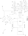
- FIG. 1 depicts embodiments of a waste heat recovery system 100.
- Embodiments of the waste heat recovery system 100 may use a waste heat such as but not exclusively the exhaust gas 11 from a drive unit 10, in the form of a gas turbine, that is used to drive a compressor 30 or other auxiliary systems related to the train, such as an oil pump, cooling fan(s), cooling water pump, a seal system compression, etc., to heat a working fluid in a closed loop system that produces mechanical power.
- a waste heat such as but not exclusively the exhaust gas 11 from a drive unit 10
- a compressor 30 such as an oil pump, cooling fan(s), cooling water pump, a seal system compression, etc.
- the waste heat 11 may also be utilized from one or more other heat sources that is part of the cycle, which may be in addition to the drive unit 10.
- the waste heat 11 may be eventually used to power directly or to assist in powering, driving, and/or running the compression process of the compressor 30. Utilizing the waste heat 11 to assist in powering the compressor 30 or other components or auxiliary systems may eliminate many limiting factors of the typical waste heat recovery scenarios. Moreover, embodiments of the waste heat recovery system 100 may use the power directly to assist in a drive train shaft power, thereby creating many advantages to one or more existing arrangements. These advantages include a reduced complexity due to elimination of a generator and all associated switchgear and wiring, and a greater efficiency due to direct use of the power without the losses associated with converting the mechanical power into electricity, transmission losses, and further losses when converting the electricity back to mechanical power.
- an Organic Rankine Cycle may be used to convert the waste heat 11 from the drive unit 10 or other heat source to a mechanical power transmitted through a pinion shaft 47 to the compressor 30.
- the mechanical power transmitted to the compressor 30 through implementation of the waste heat recovery system 100 may reduce a power required directly from the drive unit 10 to drive/power the compressor 30, thereby increasing overall system efficiency.
- embodiments of the waste heat recovery system 100 may result in the drive unit 10 requiring less fuel/gas, and therefore producing fewer emissions, which are both highly desirable outcomes.
- employing the waste heat recovery system 100 may allow the use of a smaller drive unit/gas turbine (compared to a size required if the waste heat is not converted to power used by the compressor).
- While exemplary embodiments may use an Organic Rankine Cycle (ORC), other working fluids, such as water (steam) or even different thermodynamic cycles may be used.
- ORC Organic Rankine Cycle
- other working fluids such as water (steam) or even different thermodynamic cycles may be used.
- the power may be fed to a pinion, such as a pinion that connects to a drive gear in the compressor 30, and this pinion may or may not also have an impeller, or the power may be fed directly to one or more compressor stages.
- a pinion such as a pinion that connects to a drive gear in the compressor 30, and this pinion may or may not also have an impeller, or the power may be fed directly to one or more compressor stages. Exemplary embodiments of the waste heat recovery system 100 are shown and described below with reference to FIGs. 1-3 .
- Embodiments of the waste heat recovery system 100 include a driving unit 10.
- the driving unit 10 may be a gas turbine, a gas engine, a piston, a driver, and the like, or any device that is configured to perform work and give off heat.
- Embodiments of the drive unit 10 include a drive shaft 12.
- the drive shaft 12 is driven by the drive unit 10.
- Embodiments of the drive unit 10 or driving source, such as a gas turbine may drive, rotate, or otherwise transmit torque to the drive shaft 12 or other shaft or armature of a machine.
- the drive unit 10 interfaces with the compressor 30 to actuate/operate one or more compressor stages.
- the drive unit 10 may cooperate with a drive gear 35 of the compressor 30, which meshes with or otherwise mechanically engages a plurality of pinions, such as a first pinion 41, a second pinion 42, and a third pinion 43. Accordingly, the plurality of pinions 41, 42, 43 are rotated in response to the rotation of the drive shaft 12 and drive gear 35, which is rotated by the drive unit 10.
- waste heat 11 of the drive unit 10 is received by the waste heat recovery cycle 50.
- waste heat 11 may be received, collected, accepted, obtained, recovered by the waste heat recovery cycle 50, or otherwise introduced into the waste heat recovery cycle 50.
- the waste heat recovery cycle 50 may be powered by the hot waste heat exhaust 11 from the drive unit 10, such as a gas turbine.
- Embodiments of the waste heat recovery cycle 50 are operably connected to the drive unit 10.
- the waste heat recovery cycle 50 may be in fluid communication with the drive unit 10.
- the waste heat recovery cycle 50 may be connected to the drive unit 10 by one or more pipes, lines, pipelines, ducts, tubes, or other means for passing a fluid from a first component to a second component.
- the waste heat 11 may travel from the drive unit 10 through one or more pipes to the waste heat recovery cycle 50.
- Embodiments of the waste heat recovery cycle 50 may be an organic rankine cycle, or other thermodynamic cycle, that may convert heat into work.
- the organic rankine cycle may include a working fluid, the working fluid being various, known working fluids associated with the organic rankine cycle. In other thermodynamic cycles, a working fluid may be water (steam).
- the cycle 50 may be a closed loop cycle, wherein the waste heat 11 of the drive unit 10 is supplied externally to the closed loop.
- the waste heat 11 may be indirectly transferred to the waste heat recovery loop 50 (e.g. to the evaporator 51) through an additional transfer medium, such as employing a thermal oil loop.
- Embodiments of the waste heat recovery cycle 50 may include an evaporator 51, an expansion mechanism 55, a condenser 54, and a pump 52.
- the components of the cycle 50 may be operably connected to each other in a closed loop.
- Embodiments of the evaporator 51 may be a heat exchanger, configured to evaporate a working fluid, such as a high pressure liquid flowing through the closed loop cycle 50. For instance, the hot exhaust gasses from the drive unit 10 may flow through the evaporator 51 to evaporate the working fluid of the cycle 50.
- the working fluid of the cycle 50 may be evaporated to a gaseous form/phase, and the gas may be directed to the expansion mechanism 55, thus generating power that may be transmitted to the compressor 30 through a coupling between the expansion mechanism 55 and the compressor 30, wherein the coupling may be a shaft, a rotating shaft, pinion shaft etc., depicted as pinion shaft 47 in FIG. 1 .
- Embodiments of the expansion mechanism 55 may be operably connected to the evaporator 51 via one or more lines, pipes, etc. to transfer or otherwise direct the evaporated working fluid to the expansion mechanism 55.
- Embodiments of the expansion mechanism 55 may be an expansion device, an expander, a turboexpander, and the like, configured to remove or otherwise harness energy from the high-pressured gas from the evaporator 51 to produce mechanical power.
- embodiments of the expansion mechanism 55 may be an expansion turbine, screw, tooth, scroll, and the like.
- embodiments of the expansion mechanism 55 are operably connected to the compressor 30.
- the expansion mechanism 55 may be mechanically coupled to the compressor 30 via a pinion shaft 47.
- the expansion mechanism 55 may be mechanically coupled to one end of the pinion shaft 47.
- the opposing end of the pinion shaft 47 may be operably mechanically coupled to the compressor 30.
- the opposing end of the pinion shaft 47 may be operably connected to the second pinion 42 associated with a second compressor stage 32 of the compressor 30.
- the expansion mechanism 55 may be connected to or otherwise mounted on a pinion that runs closest to an ideal speed for the expansion mechanism 55 and such pinion does not have a compressor stage mounted on it. Accordingly, embodiments of the expansion mechanism 55, through receiving the gas from the evaporator 51 may turn, rotate, or otherwise act upon the pinion shaft 47 to assist the operating/powering of the compressor 30, which may be in addition to the drive/power supplied by the drive unit 10.
- Embodiments of the compressor 30 may be an integrally geared compressor, a piston compressor, a barrel compressor, a portable compressor, and the like. Compressor 30 may be used for various gas compression applications.
- Embodiments of compressor 30 may be a centrifugal compressor having of one or more centrifugal compressor stages 31, 32, 33.
- the integrated compressor stages 31, 32, 33 may be arranged in a single gearbox, or housing.
- System requirements may determine a configuration of the compressor 30 and/or a number of compression stages.
- embodiments of compressor 30 may be a multistage compressor, wherein system requirements may dictate a number of centrifugal compression stages.
- compressor 30 includes a gear system.
- Embodiments of the gear system may be integrated into or arranged in a single housing.
- the housing may be a gearbox that houses, receives, supports, accommodates, etc., the components of the gear system of the compressor 30.
- Embodiments of the gear system of the compressor 30 may include a drive shaft 12 that is driven by the drive unit 10, a drive gear 35, a first pinion shaft 44, a first pinion 41, a second pinion shaft 46, a second pinion 42, a third pinion shaft 45, and a third pinion 43.
- three pinions mesh with the drive gear (or bull gear), wherein one pinion is on each side of the drive gear and one pinion on the top of the drive gear.
- an idler gear may be disposed between the drive gear and the compressor.
- Embodiments of the gear system of the compressor 30 include a drive shaft 12 and a drive gear 35.
- the drive gear 35 is operably mounted to the drive shaft 12.
- the drive gear 35 may be fastened to the drive shaft 12, wherein rotation of the drive shaft 12 translates to rotation of the drive gear 35.
- the drive gear 35 may be structurally integral with the drive shaft 12.
- the drive shaft 12 may protrude from a front face of the drive gear 35 along a central axis of the drive gear 35, and may also protrude from a back face of the drive gear 35 along the central axis of the drive gear 35.
- Embodiments of the drive gear 35 may include teeth along an outer, circumferential surface of the drive gear 35.
- the gear teeth of drive gear 35 may have various spacing, thickness, pitch, size, and the like. Similarly, a size of the drive gear 35 may vary to accomplish different desired speeds, ratios, torque transmission, and the like, of the gear system.
- Embodiments of the drive gear 35 may be disposed in the housing of the compressor 30. Actuation of the drive gear 35 may result in rotation of the pinions 41, 42, 43, which may then result in rotation of an impeller that may be operably attached to pinion shafts 44, 45, 46.
- a compressor stage 31, 32, 33 is operably connected to each end of the pinion shafts 44, 45, 46.
- Embodiments of a compressor stage 31, 32, 33 may be an impeller of a centrifugal compressor that is directly mounted to an end of the pinion shafts 44, 45, 46, wherein a gas is drawn in to be compressed by the compressor 30.
- a centrifugal compressor disposed at the end of the first pinion shaft 44 may be a first stage of compression 31
- a centrifugal compressor disposed at the end of the second pinion shaft 46 may be a second stage of compression 32
- a centrifugal compressor disposed at the end of the third pinion shaft 45 may be a third stage of compression 33.
- additional compression stages may be disposed at other ends of the pinion shafts 44, 45, 46.
- embodiments of the expansion mechanism 55 may cooperate with a component of the compressor 30, such as pinion shaft 47, to assist the driving/powering of the compressor 30.
- the operation of the expansion mechanism 55 may result in exhaust gas, which may be directed to a condenser 54 of the waste heat recovery cycle 50.
- the gas leaving the expansion mechanism 55 may travel though one or more lines or pipes from the expansion mechanism 55 to a condenser 54, where the gas is condensed by the condenser 54.
- Embodiments of the condenser 54 may be configured to condense the exhaust gas to a liquid form.
- the gas may be condensed to a liquid form as a result of the ambient air, or by cooling water, or other means known in the art.
- the condenser 54 may condense the gas to a liquid, which may then be used as and/or combined with the working fluid of the waste heat recovery cycle 50.
- a pressure of the liquid as a result of the condenser 54 may be increased by one or more pumps 52.
- Embodiments of the pump 52 may be configured to increase the pressure of the condensed liquid within the cycle 50 between the condenser 54 and the evaporator 51, as well as cause the liquid to flow back to the evaporator 51.
- embodiments of the waste heat recovery system 100 includes an integrally geared centrifugal compressor 30 that includes a first compressor stage 31, a second compressor stage 32, and a third compressor stage 33.
- Each of the compressor stages 31, 32, 33 may be mounted on respective pinions 41, 42, 43 which meshes with a central driving gear 35.
- Embodiments of the expansion mechanism 55 may be mounted on an end of a pinion shaft, such as pinion shaft 47, associated with the second pinion 42.
- FIG. 1 depicts the expansion mechanism 55 mounted to a shaft associated with the second pinion 42, an expansion mechanism 55 may be mounted to any of the pinions 41, 42, 43 (or pinion shafts thereof) that may have a free end (e.g.
- no compressor stage therein may be mounted on a pinion that is not associated with a compressor stage.
- some heat recovery situations may require multiple stages of expansion to best match the cycle used with the available waste heat and system conditions, and these stages may be mounted on one or more pinions.
- compressor stages 31, 32, 33 are mounted only on one end of each pinion shafts 44, 45, 46, compressor stages may be mounted on each end, and/or expander stages may be mounted on each end, and/or expander stages may be mounted on one end without a compressor stage on the other.
- the number of pinions may vary with the application, from as few as just one to as many as can be mounted with the gear.
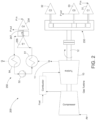
- FIG. 2 depicts an example of the waste heat recovery system 200 having an integrally geared centrifugal compressor 230 that has four compressor stages 31, 32, 33, 234, wherein the first compression stage 31, the second compression stage 32, and the third compression stage 33 may be mounted on pinions which mesh with a central driving gear, such as gear 35.
- Examples of the fourth compressor stage 234 may be mounted on a shaft 247 that may include an expansion mechanism 255 mounted on an end of the shaft 247.
- the shaft 247 may be separate from a gearbox of the compressor 230, in an arrangement that may be referred to as a compander. Use of a compander may allow the waste heat recovery system 200 to be conveniently utilized in fairly standard design practices.
- the expansion mechanism 255 may be connected to the compressor stage that runs closest to the ideal speed for the turbine.
- any compressor stage may be driven by the waste heat recovery turbine; it is not necessary have the turbine drive the last compression stage.
- some heat recovery situations may require multiple stages of expansion to best match the cycle used with the available waste heat and system conditions, so multiple companders may be used or these stages may be mounted on one or more pinions of the compressor 230.
- compressor stages 31, 32, 33, 234 are mounted only on one end of each pinion shafts 44, 45, 46, 247, compressor stages may be mounted on each end, and/or expander stages may be mounted on each end, and/or expander stages may be mounted on one end without a compressor stage on the other.
- shaft 247 along with expansion mechanism 255 and compressor 234 may be mounted in the gearbox of the compressor 230 without connecting with either drive gear 35 or idler gear 36.
- embodiments of the waste heat recovery system 300 utilize waste heat 11 from the drive unit 10 to assist in powering the compressor 330.
- the waste heat 11 may be received by the waste heat recovery cycle 350 by the evaporator 51.
- the evaporator 51 may utilize the waste heat 11 to evaporate a working fluid of the cycle 350, which may then be delivered to the expansion mechanism 355.
- Embodiments of the expansion mechanism 355 may be operably positioned at an end of the compressor shaft 322 of the compressor 330. An operation of the expansion mechanism 355 may act upon the drive shaft 312, which may assist the drive unit 10 in rotating the drive shaft 312 to power the compressor 330.
Landscapes
- Engineering & Computer Science (AREA)
- Mechanical Engineering (AREA)
- General Engineering & Computer Science (AREA)
- Chemical & Material Sciences (AREA)
- Combustion & Propulsion (AREA)
- Structures Of Non-Positive Displacement Pumps (AREA)
- Engine Equipment That Uses Special Cycles (AREA)
Description
- This application is a non-provisional application that claims priority to and the benefit of
U.S. Provisional Application No. 62/431,491, filed December 8, 2016 - The following relates to system for waste heat recovery, and more specifically to embodiments of a system and method for using waste heat from a drive unit to assist in powering a compressor and/or other auxiliary systems.
- Gas turbines are a common choice as a compressor driver in regions where electrical power is not readily available. Compressors driven by gas turbines, which include types such as piston, barrel or integrally geared centrifugal compressors, are often used to facilitate the transport of gas in pipelines. In this installation scheme, the gas turbine uses some of the gas from the pipeline as fuel for the gas turbine that powers the compressor to re-pressurize the pipeline gas to overcome the losses that occur due to the transportation process.
- Although gas turbine manufacturers have done their best to capture as much energy as possible from the combustion process, all gas turbines inherently produce waste heat. In some cases, a Heat Recovery through Steam Generation (HRSG) system is employed to convert this waste heat to electricity (this is also known as a form of Cogeneration in the power industry). In other cases, the waste heat is used directly, such for HVAC heating. However, most of the gas turbines used to drive compressors are located in remote regions where there often is no use for either electricity or HVAC; thus, the waste heat is thrown away, representing a permanent loss.
- Thus, a need exists for a system and method that can capture the waste heat from the gas turbine and use the waste heat to assist in driving the compressor.
-
US 2016/281543 describes a combined cycle power plant with a gas turbine, a shaft connecting a compressor to a turbine and a first generator, a heat recovery steam generator fluidly connected to the exhaust of the gas turbine. -
US 5.485.719 describes a method and a system for supplying compressed air to a process plant using a combustor-turbine unit directly coupled to a bull gear meshing with pinion on which are mounted gas compression stages and expansion stages. Direct energy transfers and intercooling and aftercooling after compression stages enhance the efficiency of the system. -
US 4.057.371 describes a high speed centrifugal compressor which is closely directly coupled to the power turbine of a two-shaft gas turbine having a gas generator section separate fromits power turbine. Through the direct close coupling and centerline mounting of the gas turbine exhaust casing for free and uniform heat expansion, alignment between stationary and rotating parts of the power turbine and compressor is maintained free from mechanical problems. -
US 2016/230771 describes a geared turbomachine having a gear unit, a drive unit, and output units integrated into a machine train, a central large gear with a large gear shaft and at least two pinions with at least two pinion shafts meshing with the large gear. The geared turbomachine has a drive unit coupled to a first pinion shaft of the gear unit via a first clutch. A first output unit is a main compressor processes a first process gas. The first output unit is coupled to the first pinion shaft via a second clutch such that the first output unit is directly operationally connected to the drive unit with transmission of the gear unit remaining the same. -
US 2016/222947 describes a power plant comprising an integrally geared vapor compressor arrangement, comprised of a bull gear and a compressor shaft with a pinion meshing with the bull gear. The plant further comprises a vapor source, fluidly connectable with an inlet of the integrally geared vapor compressor arrangement. A vapor turbine arrangement is fluidly connectable with an outlet of the integrally geared vapor compressor arrangement for receiving a stream of compressed and superheated vapor from the integrally geared vapor compressor arrangement. An electric generator driven by the vapor turbine arrangement converts mechanical power produced by the vapor turbine arrangement into electric power. - The invention relates to a waste heat recovery system according to claim 1 and to a method of using waste heat recovery to assist in driving/powering a compression system according to claim 4.
- The foregoing and other features of construction and operation will be more readily understood and fully appreciated from the following detailed disclosure, taken in conjunction with accompanying drawings.
- Some of the embodiments will be described in detail, with reference to the following figures, wherein like designations denote like members, wherein:
-
FIG. 1 depicts a schematic illustration of a first embodiment - of a waste heat recovery system according to the invention;
-
FIG. 2 depicts a schematic illustration of a waste heat recovery system not forming part of the invention; and -
FIG. 3 depicts a schematic illustration of another embodiment of the waste heat recovery system of the invention. - A detailed description of the hereinafter described embodiments of the disclosed apparatus and method are presented herein by way of exemplification and not limitation with reference to the Figures. Although certain embodiments are shown and described in detail, it should be understood that various changes and modifications may be made without departing from the scope of the appended claims. The scope of the present disclosure will in no way be limited to the number of constituting components, the materials thereof, the shapes thereof, the relative arrangement thereof, etc., and are disclosed simply as an example of embodiments of the present disclosure.
- As a preface to the detailed description, it should be noted that, as used in this specification and the appended claims, the singular forms "a", "an" and "the" include plural referents, unless the context clearly dictates otherwise.
- Referring to the drawings,
FIG. 1 depicts embodiments of a wasteheat recovery system 100. Embodiments of the wasteheat recovery system 100 may use a waste heat such as but not exclusively theexhaust gas 11 from adrive unit 10, in the form of a gas turbine, that is used to drive acompressor 30 or other auxiliary systems related to the train, such as an oil pump, cooling fan(s), cooling water pump, a seal system compression, etc., to heat a working fluid in a closed loop system that produces mechanical power. Although embodiments of the present invention may be described with respect to a waste heat source of adrive unit 10, thewaste heat 11 may also be utilized from one or more other heat sources that is part of the cycle, which may be in addition to thedrive unit 10. Thewaste heat 11 may be eventually used to power directly or to assist in powering, driving, and/or running the compression process of thecompressor 30. Utilizing thewaste heat 11 to assist in powering thecompressor 30 or other components or auxiliary systems may eliminate many limiting factors of the typical waste heat recovery scenarios. Moreover, embodiments of the wasteheat recovery system 100 may use the power directly to assist in a drive train shaft power, thereby creating many advantages to one or more existing arrangements. These advantages include a reduced complexity due to elimination of a generator and all associated switchgear and wiring, and a greater efficiency due to direct use of the power without the losses associated with converting the mechanical power into electricity, transmission losses, and further losses when converting the electricity back to mechanical power. - In an exemplary embodiment of the waste
heat recovery system 100, an Organic Rankine Cycle (ORC) may be used to convert thewaste heat 11 from thedrive unit 10 or other heat source to a mechanical power transmitted through apinion shaft 47 to thecompressor 30. The mechanical power transmitted to thecompressor 30 through implementation of the wasteheat recovery system 100 may reduce a power required directly from thedrive unit 10 to drive/power thecompressor 30, thereby increasing overall system efficiency. For example, embodiments of the wasteheat recovery system 100 may result in thedrive unit 10 requiring less fuel/gas, and therefore producing fewer emissions, which are both highly desirable outcomes. In some embodiments, employing the wasteheat recovery system 100 may allow the use of a smaller drive unit/gas turbine (compared to a size required if the waste heat is not converted to power used by the compressor). - While exemplary embodiments may use an Organic Rankine Cycle (ORC), other working fluids, such as water (steam) or even different thermodynamic cycles may be used. Further, there are a number of different ways in which the power derived from the
waste heat 11 can be used for assisting the powering of thecompressor 30. For instance, the power may be fed to a pinion, such as a pinion that connects to a drive gear in thecompressor 30, and this pinion may or may not also have an impeller, or the power may be fed directly to one or more compressor stages. Exemplary embodiments of the wasteheat recovery system 100 are shown and described below with reference toFIGs. 1-3 . - With continued reference to
FIG. 1 , embodiments of the wasteheat recovery system 100 include adriving unit 10, a wasteheat recovery cycle 50, and acompressor 30. Embodiments of the wasteheat recovery system 100 include adrive unit 10, thedrive unit 10 having adrive shaft 12, acompressor 30, thecompressor 30 operably coupled to thedrive shaft 12, wherein operation of thedrive unit 10 drives thecompressor 30, and a wasteheat recovery cycle 50, the wasteheat recovery cycle 50 coupled to thedrive unit 10 and thecompressor 30, wherein awaste heat 11 of thedrive unit 10 powers the wasteheat recovery cycle 50, such that the wasteheat recovery cycle 50 transmits a mechanical power to thecompressor 30. In an exemplary embodiment, the wasteheat recovery system 100 may convert, utilize, harness, use, utilize, etc. waste or exhaust heat (e.g. exhaust gas) from a turbine, engine, piston, driver, drive unit into shaft power. For example, waste heat, such as warm and/or hot exhaust gas may be recovered, captured, etc. and used to add shaft power to a compressor unit. - Embodiments of the waste
heat recovery system 100 include adriving unit 10. In an exemplary embodiment, thedriving unit 10 may be a gas turbine, a gas engine, a piston, a driver, and the like, or any device that is configured to perform work and give off heat. Embodiments of thedrive unit 10 include adrive shaft 12. Thedrive shaft 12 is driven by thedrive unit 10. Embodiments of thedrive unit 10 or driving source, such as a gas turbine, may drive, rotate, or otherwise transmit torque to thedrive shaft 12 or other shaft or armature of a machine. When thedrive shaft 12 is acted upon by thedrive unit 10, thedrive unit 10 interfaces with thecompressor 30 to actuate/operate one or more compressor stages. In an embodiment where thecompressor 30 is an integrally geared compressor, thedrive unit 10 may cooperate with adrive gear 35 of thecompressor 30, which meshes with or otherwise mechanically engages a plurality of pinions, such as afirst pinion 41, asecond pinion 42, and athird pinion 43. Accordingly, the plurality ofpinions drive shaft 12 and drivegear 35, which is rotated by thedrive unit 10. - As a result of the
drive unit 10 operating to rotate thedrive shaft 12, hot exhaust gases, such aswaste heat 11, are given off by thedrive unit 10. Thewaste heat 11 of thedrive unit 10 is received by the wasteheat recovery cycle 50. For instance,waste heat 11 may be received, collected, accepted, obtained, recovered by the wasteheat recovery cycle 50, or otherwise introduced into the wasteheat recovery cycle 50. In other words, the wasteheat recovery cycle 50 may be powered by the hotwaste heat exhaust 11 from thedrive unit 10, such as a gas turbine. Embodiments of the wasteheat recovery cycle 50 are operably connected to thedrive unit 10. In an exemplary embodiment, the wasteheat recovery cycle 50 may be in fluid communication with thedrive unit 10. In another embodiment, the wasteheat recovery cycle 50 may be connected to thedrive unit 10 by one or more pipes, lines, pipelines, ducts, tubes, or other means for passing a fluid from a first component to a second component. Thewaste heat 11 may travel from thedrive unit 10 through one or more pipes to the wasteheat recovery cycle 50. Embodiments of the wasteheat recovery cycle 50 may be an organic rankine cycle, or other thermodynamic cycle, that may convert heat into work. The organic rankine cycle may include a working fluid, the working fluid being various, known working fluids associated with the organic rankine cycle. In other thermodynamic cycles, a working fluid may be water (steam). Thecycle 50 may be a closed loop cycle, wherein thewaste heat 11 of thedrive unit 10 is supplied externally to the closed loop. In further embodiments, thewaste heat 11 may be indirectly transferred to the waste heat recovery loop 50 (e.g. to the evaporator 51) through an additional transfer medium, such as employing a thermal oil loop. - Embodiments of the waste
heat recovery cycle 50 may include anevaporator 51, anexpansion mechanism 55, acondenser 54, and apump 52. The components of thecycle 50 may be operably connected to each other in a closed loop. Embodiments of theevaporator 51 may be a heat exchanger, configured to evaporate a working fluid, such as a high pressure liquid flowing through theclosed loop cycle 50. For instance, the hot exhaust gasses from thedrive unit 10 may flow through theevaporator 51 to evaporate the working fluid of thecycle 50. By operation of thewaste heat 11 flowing through theevaporator 51, the working fluid of thecycle 50 may be evaporated to a gaseous form/phase, and the gas may be directed to theexpansion mechanism 55, thus generating power that may be transmitted to thecompressor 30 through a coupling between theexpansion mechanism 55 and thecompressor 30, wherein the coupling may be a shaft, a rotating shaft, pinion shaft etc., depicted aspinion shaft 47 inFIG. 1 . Embodiments of theexpansion mechanism 55 may be operably connected to theevaporator 51 via one or more lines, pipes, etc. to transfer or otherwise direct the evaporated working fluid to theexpansion mechanism 55. - Embodiments of the
expansion mechanism 55 may be an expansion device, an expander, a turboexpander, and the like, configured to remove or otherwise harness energy from the high-pressured gas from theevaporator 51 to produce mechanical power. Specifically, embodiments of theexpansion mechanism 55 may be an expansion turbine, screw, tooth, scroll, and the like. Moreover, embodiments of theexpansion mechanism 55 are operably connected to thecompressor 30. In exemplary embodiments, theexpansion mechanism 55 may be mechanically coupled to thecompressor 30 via apinion shaft 47. For example, theexpansion mechanism 55 may be mechanically coupled to one end of thepinion shaft 47. The opposing end of thepinion shaft 47 may be operably mechanically coupled to thecompressor 30. In one embodiment, the opposing end of thepinion shaft 47 may be operably connected to thesecond pinion 42 associated with asecond compressor stage 32 of thecompressor 30. In other embodiments, theexpansion mechanism 55 may be connected to or otherwise mounted on a pinion that runs closest to an ideal speed for theexpansion mechanism 55 and such pinion does not have a compressor stage mounted on it. Accordingly, embodiments of theexpansion mechanism 55, through receiving the gas from theevaporator 51 may turn, rotate, or otherwise act upon thepinion shaft 47 to assist the operating/powering of thecompressor 30, which may be in addition to the drive/power supplied by thedrive unit 10. - Embodiments of the
compressor 30 may be an integrally geared compressor, a piston compressor, a barrel compressor, a portable compressor, and the like.Compressor 30 may be used for various gas compression applications. Embodiments ofcompressor 30 may be a centrifugal compressor having of one or more centrifugal compressor stages 31, 32, 33. In some embodiments, the integrated compressor stages 31, 32, 33 may be arranged in a single gearbox, or housing. System requirements may determine a configuration of thecompressor 30 and/or a number of compression stages. For example, embodiments ofcompressor 30 may be a multistage compressor, wherein system requirements may dictate a number of centrifugal compression stages. Moreover,compressor 30 includes a gear system. Embodiments of the gear system may be integrated into or arranged in a single housing. The housing may be a gearbox that houses, receives, supports, accommodates, etc., the components of the gear system of thecompressor 30. Embodiments of the gear system of thecompressor 30 may include adrive shaft 12 that is driven by thedrive unit 10, adrive gear 35, a first pinion shaft 44, afirst pinion 41, asecond pinion shaft 46, asecond pinion 42, athird pinion shaft 45, and athird pinion 43. In one embodiment of the geared compressor, three pinions mesh with the drive gear (or bull gear), wherein one pinion is on each side of the drive gear and one pinion on the top of the drive gear. Further, an idler gear may be disposed between the drive gear and the compressor. - Embodiments of the gear system of the
compressor 30 include adrive shaft 12 and adrive gear 35. Thedrive gear 35 is operably mounted to thedrive shaft 12. For instance, thedrive gear 35 may be fastened to thedrive shaft 12, wherein rotation of thedrive shaft 12 translates to rotation of thedrive gear 35. In other embodiments, thedrive gear 35 may be structurally integral with thedrive shaft 12. Thedrive shaft 12 may protrude from a front face of thedrive gear 35 along a central axis of thedrive gear 35, and may also protrude from a back face of thedrive gear 35 along the central axis of thedrive gear 35. Embodiments of thedrive gear 35 may include teeth along an outer, circumferential surface of thedrive gear 35. The gear teeth ofdrive gear 35 may have various spacing, thickness, pitch, size, and the like. Similarly, a size of thedrive gear 35 may vary to accomplish different desired speeds, ratios, torque transmission, and the like, of the gear system. Embodiments of thedrive gear 35 may be disposed in the housing of thecompressor 30. Actuation of thedrive gear 35 may result in rotation of thepinions pinion shafts - Furthermore, a
compressor stage pinion shafts compressor stage pinion shafts compressor 30. In an exemplary embodiment, a centrifugal compressor disposed at the end of the first pinion shaft 44 may be a first stage ofcompression 31, a centrifugal compressor disposed at the end of thesecond pinion shaft 46 may be a second stage ofcompression 32, and a centrifugal compressor disposed at the end of thethird pinion shaft 45 may be a third stage ofcompression 33. However, in further embodiments, additional compression stages may be disposed at other ends of thepinion shafts - Referring still to
FIG. 1 , embodiments of theexpansion mechanism 55 may cooperate with a component of thecompressor 30, such aspinion shaft 47, to assist the driving/powering of thecompressor 30. The operation of theexpansion mechanism 55 may result in exhaust gas, which may be directed to acondenser 54 of the wasteheat recovery cycle 50. For instance, the gas leaving theexpansion mechanism 55 may travel though one or more lines or pipes from theexpansion mechanism 55 to acondenser 54, where the gas is condensed by thecondenser 54. Embodiments of thecondenser 54 may be configured to condense the exhaust gas to a liquid form. The gas may be condensed to a liquid form as a result of the ambient air, or by cooling water, or other means known in the art. In an exemplary embodiment, thecondenser 54 may condense the gas to a liquid, which may then be used as and/or combined with the working fluid of the wasteheat recovery cycle 50. A pressure of the liquid as a result of thecondenser 54 may be increased by one or more pumps 52. Embodiments of thepump 52 may be configured to increase the pressure of the condensed liquid within thecycle 50 between thecondenser 54 and theevaporator 51, as well as cause the liquid to flow back to theevaporator 51. - In one exemplary embodiment, depicted by
FIG. 1 , embodiments of the wasteheat recovery system 100 includes an integrally gearedcentrifugal compressor 30 that includes afirst compressor stage 31, asecond compressor stage 32, and athird compressor stage 33. Each of the compressor stages 31, 32, 33 may be mounted onrespective pinions central driving gear 35. Embodiments of theexpansion mechanism 55 may be mounted on an end of a pinion shaft, such aspinion shaft 47, associated with thesecond pinion 42. AlthoughFIG. 1 depicts theexpansion mechanism 55 mounted to a shaft associated with thesecond pinion 42, anexpansion mechanism 55 may be mounted to any of thepinions pinion shafts - The
compressor 30 may also include idler gears, such as idler gear 36. Such idler gears may be disposed between two pinions as shown inFIG. 1 , or may be between the drive gear and one or more pinions; i.e. an idler gear may drive multiple pinions. The addition of any number of idler gears disposed in any location is within the scope of this invention. The drive gear may directly drive all pinions, or may drive one or more idler gears, or any combination thereof. - With continued reference to the drawings,
FIG. 2 depicts an example of a wasteheat recovery system 200. Examples of the wasteheat recovery system 200 may share the same or substantially the same structure and/or function as the wasteheat recovery system 100 described above. For instance, examples of the wasteheat recovery system 200 may include a drive unit, a compressor, and a waste heat recovery cycle. Examples of the wasteheat recovery cycle 250 may operate in the same or substantially the same manner as the wasteheat recovery cycle 50 described in association withFIG. 1 . However, examples of the wasteheat recovery system 200 may include anexpansion mechanism 255 mounted to ashaft 247 of thecompressor 30 that is located external to the housing of the integrally gearedcompressor 30. -
FIG. 2 depicts an example of the wasteheat recovery system 200 having an integrally gearedcentrifugal compressor 230 that has fourcompressor stages first compression stage 31, thesecond compression stage 32, and thethird compression stage 33 may be mounted on pinions which mesh with a central driving gear, such asgear 35. Examples of thefourth compressor stage 234 may be mounted on ashaft 247 that may include anexpansion mechanism 255 mounted on an end of theshaft 247. Theshaft 247 may be separate from a gearbox of thecompressor 230, in an arrangement that may be referred to as a compander. Use of a compander may allow the wasteheat recovery system 200 to be conveniently utilized in fairly standard design practices. In similar examples where a compander is used for waste heat recovery, theexpansion mechanism 255 may be connected to the compressor stage that runs closest to the ideal speed for the turbine. Thus any compressor stage may be driven by the waste heat recovery turbine; it is not necessary have the turbine drive the last compression stage. In further examples, some heat recovery situations may require multiple stages of expansion to best match the cycle used with the available waste heat and system conditions, so multiple companders may be used or these stages may be mounted on one or more pinions of thecompressor 230. Likewise, while compressor stages 31, 32, 33, 234 are mounted only on one end of eachpinion shafts shaft 247 along withexpansion mechanism 255 andcompressor 234 may be mounted in the gearbox of thecompressor 230 without connecting with eitherdrive gear 35 or idler gear 36. - Accordingly, examples of the waste
heat recovery system 200 may utilizewaste heat 11 from thedrive unit 10 to assist in powering thecompressor 230. Thewaste heat 11 may be received by the wasteheat recovery cycle 250 by theevaporator 51. Theevaporator 51 may utilize thewaste heat 11 to evaporate a working fluid of thecycle 250, which may then be delivered to theexpansion mechanism 255. Examples of theexpansion mechanism 255 may be operably positioned at an end of theshaft 247, which may be located external to a gearbox of acompressor 230, which may include multiple compression stages. An operation of theexpansion mechanism 255 may act upon a compression stage that is a part of the compression process but is independent ofdrive unit 10. - Referring again to the drawings,
FIG. 3 depicts an embodiment of wasteheat recovery system 300. Embodiments of the wasteheat recovery system 300 may share the same or substantially the same structure and/or function as the wasteheat recovery system heat recovery system 200 may include a drive unit, a compressor, and a waste heat recovery cycle. Embodiments of the wasteheat recovery cycle 350 may operate in the same or substantially the same manner as the wasteheat recovery cycle FIGs. 1 and2 . However, embodiments of the wasteheat recovery system 300 may include abarrel compressor 330 operably coupled to thedrive unit 10, with anexpansion mechanism 355 mounted at one end of a shaft connected to thedrive unit 10. -
FIG. 3 depicts an embodiment of the wasteheat recovery system 300 having a barrel-typecentrifugal compressor 330 that has multiple compressor stages, 331, 332, 333. Anexpansion mechanism 355 may be mounted at one end of thecompressor shaft 322. For instance, one end of thecompressor shaft 322 may be operably coupled to driveshaft 312 that may also be operably coupled to thedrive unit 10, while the opposing end of thecompressor shaft 322 may be operably coupled to theexpansion mechanism 355. In an alternative embodiment, theexpansion mechanism 355 may be directly coupled to thedrive unit 10. In yet another embodiment, additional expander stages may be integrated into thebarrel compressor 330. Moreover, embodiments of thecompressor 330 may be any type of shaft driven positive or dynamic compressor; including but not limited to reciprocating, rotary screw, rotary vane, rolling piston, scroll, centrifugal, mixed-flow, or axial compressors.. Some heat recovery situations may require multiple stages of expansion to best match the cycle used with the available waste heat and system conditions. - Accordingly, embodiments of the waste
heat recovery system 300 utilizewaste heat 11 from thedrive unit 10 to assist in powering thecompressor 330. Thewaste heat 11 may be received by the wasteheat recovery cycle 350 by theevaporator 51. Theevaporator 51 may utilize thewaste heat 11 to evaporate a working fluid of thecycle 350, which may then be delivered to theexpansion mechanism 355. Embodiments of theexpansion mechanism 355 may be operably positioned at an end of thecompressor shaft 322 of thecompressor 330. An operation of theexpansion mechanism 355 may act upon thedrive shaft 312, which may assist thedrive unit 10 in rotating thedrive shaft 312 to power thecompressor 330. - Each of the waste
heat recovery systems drive unit 10, such as a gas turbine, as a power source in a wasteheat recovery cycle heat recovery cycle expansion mechanism expansion mechanism compressor stage 234 or to acompressor compressor stage 234 or to acompressor compressor single drive unit 10. The transmission/transfer of the power from theexpansion mechanism - With reference to
FIGs. 1-3 , a method of using waste heat recovery to assist in driving/powering a compression system include the steps of incorporating or coupling a wasteheat recovery cycle drive unit 10 and acompressor heat recovery cycle - While this disclosure has been described in conjunction with the specific embodiments and examples outlined above, it is evident that many alternatives, modifications and variations will be apparent to those skilled in the art. Accordingly, the preferred embodiments of the present disclosure as set forth above are intended to be illustrative, not limiting. Various changes may be made without departing from the scope of the invention.
Claims (7)
- A waste heat recovery system for assisting in driving/powering a compressor (30, 230) comprising:a drive unit (10), the drive unit (10) having a drive shaft (12), wherein the drive unit (10) is a gas turbine;the compressor(30) having multiple compression stages (31, 32, 33, 234) and comprising a gear system comprising a drive gear (35) which mechanically engages a plurality of pinions (41, 42, 43) each respectively associated with a compression stage (31, 32, 33, 234), the drive gear (35) operably mounted to the drive shaft(12) such that the plurality of pinions (41, 42, 43) is rotated in response to a rotation of the drive shaft (12) and the drive gear (35), wherein operation of the drive unit (10) drives the compressor (30) by the rotation of the drive shaft (12);characterized in that the waste heat recovery system (100) further comprises:a waste heat recovery cycle (50) comprising an expansion mechanism (55) for producing mechanical power, the waste heat recovery cycle (50) coupled to the drive unit (10) and further comprising a rotating shaft (47, 247) mechanically coupled to one of the plurality of the pinions (41, 42,43);wherein a waste heat (11) of the drive unit (10) powers the expansion mechanism (55), such that the waste heat recovery cycle (50) transmits a mechanical power to the compressor (30) through the rotating shaft (47, 247).
- The waste heat recovery system of claim 1, wherein the expansion mechanism (55) is operably coupled to an opposing end (322) of the driving shaft (12) of the drive unit (10).
- The waste heat recovery system of claim 1, wherein the compressor (30) is a barrel compressor(30) having multiple compression stages (31, 32, 33).
- A method of using waste heat recovery to assist in driving/powering a compressor (30, 230), comprising:coupling a waste heat recovery cycle (50) comprising an expansion mechanism (55) for producing mechanical power to a drive unit (10) and the compressor (30, 230); wherein the expansion mechanism (55) is operably coupled to a rotating shaft (47) of the compressor (30); wherein the drive unit (10) is a gas turbine, the compressor (30, 230) having multiple compression stages (31, 32, 33, 234) and a gear system comprising a drive gear (35) which mechanically engages a plurality of pinions (41, 42, 43) each respectively associated with a compression stage (31, 32, 33, 234); anddelivering a mechanical power from the waste heat recovery cycle (50) to one of the plurality of the pinions (41, 42, 43) of the compressor (30).
- The method of claim 4, wherein the expansion mechanism (55) is operably coupled to an opposing end (322) of the driving shaft (12) of the drive unit (10).
- The method of claim 4, wherein the compressor (30) is an integrally geared compressor (30) having multiple compression stages (31, 32, 33).
- The method of claim 4, wherein the compressor (30) is a barrel compressor (30) having multiple compression stages (31, 32, 33)
Applications Claiming Priority (2)
| Application Number | Priority Date | Filing Date | Title |
|---|---|---|---|
| US201662431491P | 2016-12-08 | 2016-12-08 | |
| PCT/US2017/064200 WO2018106528A1 (en) | 2016-12-08 | 2017-12-01 | Waste heat recovery system |
Publications (3)
| Publication Number | Publication Date |
|---|---|
| EP3551864A1 EP3551864A1 (en) | 2019-10-16 |
| EP3551864A4 EP3551864A4 (en) | 2020-08-19 |
| EP3551864B1 true EP3551864B1 (en) | 2025-04-23 |
Family
ID=62489631
Family Applications (1)
| Application Number | Title | Priority Date | Filing Date |
|---|---|---|---|
| EP17878760.2A Active EP3551864B1 (en) | 2016-12-08 | 2017-12-01 | Waste heat recovery system |
Country Status (6)
| Country | Link |
|---|---|
| US (2) | US11280226B2 (en) |
| EP (1) | EP3551864B1 (en) |
| JP (1) | JP7070972B2 (en) |
| KR (1) | KR102423941B1 (en) |
| CN (2) | CN207673437U (en) |
| WO (1) | WO2018106528A1 (en) |
Families Citing this family (14)
| Publication number | Priority date | Publication date | Assignee | Title |
|---|---|---|---|---|
| DE102016107341A1 (en) * | 2016-04-20 | 2017-10-26 | Atlas Copco Energas Gmbh | Turbo engine assembly |
| KR102423941B1 (en) | 2016-12-08 | 2022-07-22 | 아틀라스 콥코 콤텍트, 엘엘씨 | Waste heat recovery system |
| US11644015B2 (en) | 2021-04-02 | 2023-05-09 | Ice Thermal Harvesting, Llc | Systems and methods for generation of electrical power at a drilling rig |
| US11592009B2 (en) | 2021-04-02 | 2023-02-28 | Ice Thermal Harvesting, Llc | Systems and methods for generation of electrical power at a drilling rig |
| US11493029B2 (en) | 2021-04-02 | 2022-11-08 | Ice Thermal Harvesting, Llc | Systems and methods for generation of electrical power at a drilling rig |
| US11359576B1 (en) | 2021-04-02 | 2022-06-14 | Ice Thermal Harvesting, Llc | Systems and methods utilizing gas temperature as a power source |
| US12312981B2 (en) | 2021-04-02 | 2025-05-27 | Ice Thermal Harvesting, Llc | Systems and methods utilizing gas temperature as a power source |
| US11293414B1 (en) | 2021-04-02 | 2022-04-05 | Ice Thermal Harvesting, Llc | Systems and methods for generation of electrical power in an organic rankine cycle operation |
| US11486370B2 (en) | 2021-04-02 | 2022-11-01 | Ice Thermal Harvesting, Llc | Modular mobile heat generation unit for generation of geothermal power in organic Rankine cycle operations |
| US11480074B1 (en) | 2021-04-02 | 2022-10-25 | Ice Thermal Harvesting, Llc | Systems and methods utilizing gas temperature as a power source |
| US11255315B1 (en) | 2021-04-02 | 2022-02-22 | Ice Thermal Harvesting, Llc | Controller for controlling generation of geothermal power in an organic Rankine cycle operation during hydrocarbon production |
| US11421663B1 (en) | 2021-04-02 | 2022-08-23 | Ice Thermal Harvesting, Llc | Systems and methods for generation of electrical power in an organic Rankine cycle operation |
| US12534990B2 (en) | 2022-12-29 | 2026-01-27 | Ice Thermal Harvesting, Llc | Power generation assemblies for hydraulic fracturing systems and methods |
| US12180861B1 (en) | 2022-12-30 | 2024-12-31 | Ice Thermal Harvesting, Llc | Systems and methods to utilize heat carriers in conversion of thermal energy |
Family Cites Families (45)
| Publication number | Priority date | Publication date | Assignee | Title |
|---|---|---|---|---|
| US3148503A (en) * | 1960-05-25 | 1964-09-15 | Ca Nat Research Council | Combined gas and steam power plant |
| US3215342A (en) * | 1964-03-23 | 1965-11-02 | Perez Gabriel | Centrifugal air compressor |
| GB1168081A (en) * | 1966-02-18 | 1969-10-22 | Ass Elect Ind | Improvements relating to Gas Turbine Plants |
| US3731495A (en) * | 1970-12-28 | 1973-05-08 | Union Carbide Corp | Process of and apparatus for air separation with nitrogen quenched power turbine |
| US3796045A (en) * | 1971-07-15 | 1974-03-12 | Turbo Dev Inc | Method and apparatus for increasing power output and/or thermal efficiency of a gas turbine power plant |
| US3976165A (en) * | 1974-05-03 | 1976-08-24 | Norwalk-Turbo, Inc. | Lubricating and oil seal system for a high speed compressor |
| US4057371A (en) | 1974-05-03 | 1977-11-08 | Norwalk-Turbo Inc. | Gas turbine driven high speed centrifugal compressor unit |
| US3942908A (en) * | 1974-05-03 | 1976-03-09 | Norwalk-Turbo, Inc. | Gas turbine driven high speed centrifugal compressor unit |
| US4204401A (en) * | 1976-07-19 | 1980-05-27 | The Hydragon Corporation | Turbine engine with exhaust gas recirculation |
| JPS544906A (en) | 1977-06-15 | 1979-01-16 | Nippon Oil & Fats Co Ltd | Production of hard butter and highly stable liquid oil |
| US4271664A (en) * | 1977-07-21 | 1981-06-09 | Hydragon Corporation | Turbine engine with exhaust gas recirculation |
| DE2802730C2 (en) | 1978-01-23 | 1985-11-21 | Agfa-Gevaert Ag, 5090 Leverkusen | X-ray film cassette |
| CH630702A5 (en) * | 1978-04-26 | 1982-06-30 | Sulzer Ag | PLANT FOR PRODUCING PRESSURE GAS. |
| JP2547760B2 (en) * | 1987-03-20 | 1996-10-23 | 株式会社東芝 | Control device for combined cycle power plant |
| US4785621A (en) * | 1987-05-28 | 1988-11-22 | General Electric Company | Air bottoming cycle for coal gasification plant |
| US5402631A (en) * | 1991-05-10 | 1995-04-04 | Praxair Technology, Inc. | Integration of combustor-turbine units and integral-gear pressure processors |
| US5813215A (en) * | 1995-02-21 | 1998-09-29 | Weisser; Arthur M. | Combined cycle waste heat recovery system |
| US5595059A (en) * | 1995-03-02 | 1997-01-21 | Westingthouse Electric Corporation | Combined cycle power plant with thermochemical recuperation and flue gas recirculation |
| JPH09166002A (en) * | 1995-12-14 | 1997-06-24 | Hitachi Ltd | Combined cycle power plant |
| JPH11257026A (en) * | 1998-03-16 | 1999-09-21 | Mitsubishi Heavy Ind Ltd | Compressor plant |
| US6256994B1 (en) * | 1999-06-04 | 2001-07-10 | Air Products And Chemicals, Inc. | Operation of an air separation process with a combustion engine for the production of atmospheric gas products and electric power |
| DE19957874A1 (en) * | 1999-12-01 | 2001-06-07 | Alstom Power Schweiz Ag Baden | Combined power plant |
| US6499303B1 (en) * | 2001-04-18 | 2002-12-31 | General Electric Company | Method and system for gas turbine power augmentation |
| JP4328191B2 (en) | 2003-02-21 | 2009-09-09 | 株式会社日立製作所 | Investment recovery plan support system for estimating investment recoverability of fuel gas pipeline facility with booster and exhaust heat recovery compressor |
| US7926292B2 (en) * | 2008-03-19 | 2011-04-19 | Gas Technology Institute | Partial oxidation gas turbine cooling |
| DE102008031116B4 (en) * | 2008-05-29 | 2022-02-03 | Man Energy Solutions Se | Geared turbomachine for a machine train, machine train with and gear for geared turbomachine |
| US8001760B2 (en) * | 2008-10-09 | 2011-08-23 | Mitsubishi Heavy Industries, Ltd. | Intake air heating system of combined cycle plant |
| NO331154B1 (en) * | 2008-11-04 | 2011-10-24 | Hamworthy Gas Systems As | System for combined cycle mechanical operation in cryogenic condensation processes. |
| EP2430292A1 (en) | 2009-05-12 | 2012-03-21 | Icr Turbine Engine Corporation | Gas turbine energy storage and conversion system |
| US8863492B2 (en) * | 2010-01-19 | 2014-10-21 | Siemens Energy, Inc. | Combined cycle power plant with split compressor |
| JP5868646B2 (en) | 2011-09-28 | 2016-02-24 | 三菱重工コンプレッサ株式会社 | Rotating machine |
| WO2014033837A1 (en) * | 2012-08-28 | 2014-03-06 | 株式会社日立製作所 | Waste heat recovery boiler, method for controlling waste heat recovery boiler, and combined cycle power generation plant using same |
| CN103796747B (en) * | 2012-09-13 | 2015-08-12 | 三菱重工压缩机有限公司 | The step-up method of booster system and gas |
| JP6109529B2 (en) * | 2012-10-31 | 2017-04-05 | 三菱日立パワーシステムズ株式会社 | Power generation system |
| CN203420787U (en) * | 2013-02-28 | 2014-02-05 | 通用电气公司 | System for operating power equipment |
| KR102256476B1 (en) * | 2013-07-04 | 2021-05-27 | 한화에어로스페이스 주식회사 | Gas turbine system |
| ITFI20130238A1 (en) | 2013-10-14 | 2015-04-15 | Nuovo Pignone Srl | "POWER PLANTS WITH AN INTEGRALLY GEARED STEAM COMPRESSOR" |
| US20160273456A1 (en) * | 2013-10-16 | 2016-09-22 | General Electric Company | Gas turbine system and method |
| EP2886951A1 (en) | 2013-12-19 | 2015-06-24 | Alstom Technology Ltd | Combined cycle power plant |
| US20160047307A1 (en) * | 2014-08-15 | 2016-02-18 | General Electric Company | Power train architectures with low-loss lubricant bearings and low-density materials |
| DE102015001418A1 (en) | 2015-02-06 | 2016-08-11 | Man Diesel & Turbo Se | Geared turbine machine |
| EP3253952A2 (en) * | 2015-02-06 | 2017-12-13 | Florida Turbine Technologies, Inc. | Apparatus and process of retrofitting a combined cycle power plant |
| US10012136B2 (en) * | 2015-08-25 | 2018-07-03 | Brian Shor | System and method for recovering thermal energy for an internal combustion engine |
| GB2546723B (en) * | 2015-12-11 | 2021-06-02 | Hieta Tech Limited | Inverted brayton cycle heat engine |
| KR102423941B1 (en) * | 2016-12-08 | 2022-07-22 | 아틀라스 콥코 콤텍트, 엘엘씨 | Waste heat recovery system |
-
2017
- 2017-12-01 KR KR1020197019058A patent/KR102423941B1/en active Active
- 2017-12-01 EP EP17878760.2A patent/EP3551864B1/en active Active
- 2017-12-01 US US15/829,315 patent/US11280226B2/en active Active
- 2017-12-01 WO PCT/US2017/064200 patent/WO2018106528A1/en not_active Ceased
- 2017-12-01 JP JP2019529557A patent/JP7070972B2/en active Active
- 2017-12-08 CN CN201721697388.0U patent/CN207673437U/en active Active
- 2017-12-08 CN CN201711292953.XA patent/CN108167077A/en active Pending
-
2022
- 2022-02-07 US US17/666,070 patent/US11739666B2/en active Active
Also Published As
| Publication number | Publication date |
|---|---|
| KR102423941B1 (en) | 2022-07-22 |
| JP2020513499A (en) | 2020-05-14 |
| WO2018106528A1 (en) | 2018-06-14 |
| US11280226B2 (en) | 2022-03-22 |
| EP3551864A4 (en) | 2020-08-19 |
| US20180163733A1 (en) | 2018-06-14 |
| US20220154603A1 (en) | 2022-05-19 |
| EP3551864A1 (en) | 2019-10-16 |
| CN207673437U (en) | 2018-07-31 |
| US11739666B2 (en) | 2023-08-29 |
| JP7070972B2 (en) | 2022-05-18 |
| CN108167077A (en) | 2018-06-15 |
| KR20190091492A (en) | 2019-08-06 |
Similar Documents
| Publication | Publication Date | Title |
|---|---|---|
| US11739666B2 (en) | Waste heat recovery system | |
| EP3314096B1 (en) | Power system and method for producing useful power from heat provided by a heat source | |
| US7637108B1 (en) | Power compounder | |
| US9334761B2 (en) | Power compounder | |
| EP2713017B1 (en) | An organic rankine cycle for mechanical drive applications | |
| AU2021249399B2 (en) | Integrated hermetically sealed turboexpander-generator with an electric generator at an end of a common shaft line | |
| CN102498267B (en) | For making the device of natural gas liquefaction and the method for starting described device | |
| KR101788023B1 (en) | A centrifugal compressor | |
| US20150292349A1 (en) | Turboexpander and driven turbomachine system | |
| EP3420201B1 (en) | Waste heat recovery cascade cycle and method | |
| US11506088B2 (en) | Hydro-turbine drive methods and systems for application for various rotary machineries | |
| CN109643963B (en) | Variable speed drive and system using the same and method of operating variable speed rotating load | |
| RU2241132C1 (en) | Combination gas-turbine plant | |
| RU2811729C2 (en) | Combined-cycle power plant | |
| RU2391516C2 (en) | Steam-gas installation |
Legal Events
| Date | Code | Title | Description |
|---|---|---|---|
| STAA | Information on the status of an ep patent application or granted ep patent |
Free format text: STATUS: THE INTERNATIONAL PUBLICATION HAS BEEN MADE |
|
| PUAI | Public reference made under article 153(3) epc to a published international application that has entered the european phase |
Free format text: ORIGINAL CODE: 0009012 |
|
| STAA | Information on the status of an ep patent application or granted ep patent |
Free format text: STATUS: REQUEST FOR EXAMINATION WAS MADE |
|
| 17P | Request for examination filed |
Effective date: 20190627 |
|
| AK | Designated contracting states |
Kind code of ref document: A1 Designated state(s): AL AT BE BG CH CY CZ DE DK EE ES FI FR GB GR HR HU IE IS IT LI LT LU LV MC MK MT NL NO PL PT RO RS SE SI SK SM TR |
|
| AX | Request for extension of the european patent |
Extension state: BA ME |
|
| DAV | Request for validation of the european patent (deleted) | ||
| DAX | Request for extension of the european patent (deleted) | ||
| A4 | Supplementary search report drawn up and despatched |
Effective date: 20200720 |
|
| RIC1 | Information provided on ipc code assigned before grant |
Ipc: F01K 23/12 20060101ALI20200714BHEP Ipc: F04D 25/16 20060101ALI20200714BHEP Ipc: F04D 25/02 20060101ALI20200714BHEP Ipc: F01K 25/08 20060101ALI20200714BHEP Ipc: F02C 7/36 20060101ALI20200714BHEP Ipc: F02C 6/06 20060101ALI20200714BHEP Ipc: F04D 25/04 20060101ALI20200714BHEP Ipc: F02C 3/04 20060101AFI20200714BHEP Ipc: F01K 23/10 20060101ALI20200714BHEP Ipc: F02C 6/04 20060101ALI20200714BHEP |
|
| STAA | Information on the status of an ep patent application or granted ep patent |
Free format text: STATUS: EXAMINATION IS IN PROGRESS |
|
| 17Q | First examination report despatched |
Effective date: 20220728 |
|
| GRAP | Despatch of communication of intention to grant a patent |
Free format text: ORIGINAL CODE: EPIDOSNIGR1 |
|
| STAA | Information on the status of an ep patent application or granted ep patent |
Free format text: STATUS: GRANT OF PATENT IS INTENDED |
|
| INTG | Intention to grant announced |
Effective date: 20240816 |
|
| GRAJ | Information related to disapproval of communication of intention to grant by the applicant or resumption of examination proceedings by the epo deleted |
Free format text: ORIGINAL CODE: EPIDOSDIGR1 |
|
| STAA | Information on the status of an ep patent application or granted ep patent |
Free format text: STATUS: EXAMINATION IS IN PROGRESS |
|
| GRAP | Despatch of communication of intention to grant a patent |
Free format text: ORIGINAL CODE: EPIDOSNIGR1 |
|
| STAA | Information on the status of an ep patent application or granted ep patent |
Free format text: STATUS: GRANT OF PATENT IS INTENDED |
|
| INTC | Intention to grant announced (deleted) | ||
| INTG | Intention to grant announced |
Effective date: 20250116 |
|
| GRAS | Grant fee paid |
Free format text: ORIGINAL CODE: EPIDOSNIGR3 |
|
| GRAA | (expected) grant |
Free format text: ORIGINAL CODE: 0009210 |
|
| STAA | Information on the status of an ep patent application or granted ep patent |
Free format text: STATUS: THE PATENT HAS BEEN GRANTED |
|
| AK | Designated contracting states |
Kind code of ref document: B1 Designated state(s): AL AT BE BG CH CY CZ DE DK EE ES FI FR GB GR HR HU IE IS IT LI LT LU LV MC MK MT NL NO PL PT RO RS SE SI SK SM TR |
|
| REG | Reference to a national code |
Ref country code: GB Ref legal event code: FG4D |
|
| REG | Reference to a national code |
Ref country code: CH Ref legal event code: EP |
|
| REG | Reference to a national code |
Ref country code: DE Ref legal event code: R096 Ref document number: 602017089099 Country of ref document: DE |
|
| REG | Reference to a national code |
Ref country code: IE Ref legal event code: FG4D |
|
| REG | Reference to a national code |
Ref country code: NL Ref legal event code: MP Effective date: 20250423 |
|
| PG25 | Lapsed in a contracting state [announced via postgrant information from national office to epo] |
Ref country code: NL Free format text: LAPSE BECAUSE OF FAILURE TO SUBMIT A TRANSLATION OF THE DESCRIPTION OR TO PAY THE FEE WITHIN THE PRESCRIBED TIME-LIMIT Effective date: 20250423 |
|
| REG | Reference to a national code |
Ref country code: AT Ref legal event code: MK05 Ref document number: 1787947 Country of ref document: AT Kind code of ref document: T Effective date: 20250423 |
|
| PG25 | Lapsed in a contracting state [announced via postgrant information from national office to epo] |
Ref country code: PT Free format text: LAPSE BECAUSE OF FAILURE TO SUBMIT A TRANSLATION OF THE DESCRIPTION OR TO PAY THE FEE WITHIN THE PRESCRIBED TIME-LIMIT Effective date: 20250825 Ref country code: FI Free format text: LAPSE BECAUSE OF FAILURE TO SUBMIT A TRANSLATION OF THE DESCRIPTION OR TO PAY THE FEE WITHIN THE PRESCRIBED TIME-LIMIT Effective date: 20250423 Ref country code: ES Free format text: LAPSE BECAUSE OF FAILURE TO SUBMIT A TRANSLATION OF THE DESCRIPTION OR TO PAY THE FEE WITHIN THE PRESCRIBED TIME-LIMIT Effective date: 20250423 |
|
| REG | Reference to a national code |
Ref country code: LT Ref legal event code: MG9D |
|
| PG25 | Lapsed in a contracting state [announced via postgrant information from national office to epo] |
Ref country code: GR Free format text: LAPSE BECAUSE OF FAILURE TO SUBMIT A TRANSLATION OF THE DESCRIPTION OR TO PAY THE FEE WITHIN THE PRESCRIBED TIME-LIMIT Effective date: 20250724 Ref country code: NO Free format text: LAPSE BECAUSE OF FAILURE TO SUBMIT A TRANSLATION OF THE DESCRIPTION OR TO PAY THE FEE WITHIN THE PRESCRIBED TIME-LIMIT Effective date: 20250723 |
|
| PG25 | Lapsed in a contracting state [announced via postgrant information from national office to epo] |
Ref country code: PL Free format text: LAPSE BECAUSE OF FAILURE TO SUBMIT A TRANSLATION OF THE DESCRIPTION OR TO PAY THE FEE WITHIN THE PRESCRIBED TIME-LIMIT Effective date: 20250423 |
|
| PG25 | Lapsed in a contracting state [announced via postgrant information from national office to epo] |
Ref country code: BG Free format text: LAPSE BECAUSE OF FAILURE TO SUBMIT A TRANSLATION OF THE DESCRIPTION OR TO PAY THE FEE WITHIN THE PRESCRIBED TIME-LIMIT Effective date: 20250423 |
|
| PG25 | Lapsed in a contracting state [announced via postgrant information from national office to epo] |
Ref country code: HR Free format text: LAPSE BECAUSE OF FAILURE TO SUBMIT A TRANSLATION OF THE DESCRIPTION OR TO PAY THE FEE WITHIN THE PRESCRIBED TIME-LIMIT Effective date: 20250423 |
|
| PG25 | Lapsed in a contracting state [announced via postgrant information from national office to epo] |
Ref country code: AT Free format text: LAPSE BECAUSE OF FAILURE TO SUBMIT A TRANSLATION OF THE DESCRIPTION OR TO PAY THE FEE WITHIN THE PRESCRIBED TIME-LIMIT Effective date: 20250423 |
|
| PG25 | Lapsed in a contracting state [announced via postgrant information from national office to epo] |
Ref country code: RS Free format text: LAPSE BECAUSE OF FAILURE TO SUBMIT A TRANSLATION OF THE DESCRIPTION OR TO PAY THE FEE WITHIN THE PRESCRIBED TIME-LIMIT Effective date: 20250723 |
|
| PG25 | Lapsed in a contracting state [announced via postgrant information from national office to epo] |
Ref country code: IS Free format text: LAPSE BECAUSE OF FAILURE TO SUBMIT A TRANSLATION OF THE DESCRIPTION OR TO PAY THE FEE WITHIN THE PRESCRIBED TIME-LIMIT Effective date: 20250823 |
|
| PG25 | Lapsed in a contracting state [announced via postgrant information from national office to epo] |
Ref country code: LV Free format text: LAPSE BECAUSE OF FAILURE TO SUBMIT A TRANSLATION OF THE DESCRIPTION OR TO PAY THE FEE WITHIN THE PRESCRIBED TIME-LIMIT Effective date: 20250423 |
|
| PGFP | Annual fee paid to national office [announced via postgrant information from national office to epo] |
Ref country code: GB Payment date: 20251229 Year of fee payment: 9 |
|
| PG25 | Lapsed in a contracting state [announced via postgrant information from national office to epo] |
Ref country code: DK Free format text: LAPSE BECAUSE OF FAILURE TO SUBMIT A TRANSLATION OF THE DESCRIPTION OR TO PAY THE FEE WITHIN THE PRESCRIBED TIME-LIMIT Effective date: 20250423 Ref country code: SM Free format text: LAPSE BECAUSE OF FAILURE TO SUBMIT A TRANSLATION OF THE DESCRIPTION OR TO PAY THE FEE WITHIN THE PRESCRIBED TIME-LIMIT Effective date: 20250423 |
|
| PGFP | Annual fee paid to national office [announced via postgrant information from national office to epo] |
Ref country code: IT Payment date: 20251219 Year of fee payment: 9 |
|
| PGFP | Annual fee paid to national office [announced via postgrant information from national office to epo] |
Ref country code: FR Payment date: 20251226 Year of fee payment: 9 |
|
| PGFP | Annual fee paid to national office [announced via postgrant information from national office to epo] |
Ref country code: BE Payment date: 20251229 Year of fee payment: 9 |
|
| PG25 | Lapsed in a contracting state [announced via postgrant information from national office to epo] |
Ref country code: CZ Free format text: LAPSE BECAUSE OF FAILURE TO SUBMIT A TRANSLATION OF THE DESCRIPTION OR TO PAY THE FEE WITHIN THE PRESCRIBED TIME-LIMIT Effective date: 20250423 |
|
| PG25 | Lapsed in a contracting state [announced via postgrant information from national office to epo] |
Ref country code: EE Free format text: LAPSE BECAUSE OF FAILURE TO SUBMIT A TRANSLATION OF THE DESCRIPTION OR TO PAY THE FEE WITHIN THE PRESCRIBED TIME-LIMIT Effective date: 20250423 |
|
| REG | Reference to a national code |
Ref country code: DE Ref legal event code: R097 Ref document number: 602017089099 Country of ref document: DE |
|
| PG25 | Lapsed in a contracting state [announced via postgrant information from national office to epo] |
Ref country code: RO Free format text: LAPSE BECAUSE OF FAILURE TO SUBMIT A TRANSLATION OF THE DESCRIPTION OR TO PAY THE FEE WITHIN THE PRESCRIBED TIME-LIMIT Effective date: 20250423 Ref country code: SK Free format text: LAPSE BECAUSE OF FAILURE TO SUBMIT A TRANSLATION OF THE DESCRIPTION OR TO PAY THE FEE WITHIN THE PRESCRIBED TIME-LIMIT Effective date: 20250423 |
|
| PLBE | No opposition filed within time limit |
Free format text: ORIGINAL CODE: 0009261 |
|
| STAA | Information on the status of an ep patent application or granted ep patent |
Free format text: STATUS: NO OPPOSITION FILED WITHIN TIME LIMIT |
|
| REG | Reference to a national code |
Ref country code: CH Ref legal event code: L10 Free format text: ST27 STATUS EVENT CODE: U-0-0-L10-L00 (AS PROVIDED BY THE NATIONAL OFFICE) Effective date: 20260304 |
|
| 26N | No opposition filed |
Effective date: 20260126 |
|
| PGFP | Annual fee paid to national office [announced via postgrant information from national office to epo] |
Ref country code: DE Payment date: 20251229 Year of fee payment: 9 |