EP3551250B1 - Dispositif implantable - Google Patents
Dispositif implantable Download PDFInfo
- Publication number
- EP3551250B1 EP3551250B1 EP17809321.7A EP17809321A EP3551250B1 EP 3551250 B1 EP3551250 B1 EP 3551250B1 EP 17809321 A EP17809321 A EP 17809321A EP 3551250 B1 EP3551250 B1 EP 3551250B1
- Authority
- EP
- European Patent Office
- Prior art keywords
- implantable device
- patient
- active substance
- injector
- electrical energy
- Prior art date
- Legal status (The legal status is an assumption and is not a legal conclusion. Google has not performed a legal analysis and makes no representation as to the accuracy of the status listed.)
- Active
Links
Images


Classifications
-
- A—HUMAN NECESSITIES
- A61—MEDICAL OR VETERINARY SCIENCE; HYGIENE
- A61B—DIAGNOSIS; SURGERY; IDENTIFICATION
- A61B5/00—Measuring for diagnostic purposes; Identification of persons
- A61B5/145—Measuring characteristics of blood in vivo, e.g. gas concentration or pH-value ; Measuring characteristics of body fluids or tissues, e.g. interstitial fluid or cerebral tissue
- A61B5/14503—Measuring characteristics of blood in vivo, e.g. gas concentration or pH-value ; Measuring characteristics of body fluids or tissues, e.g. interstitial fluid or cerebral tissue invasive, e.g. introduced into the body by a catheter or needle or using implanted sensors
-
- A—HUMAN NECESSITIES
- A61—MEDICAL OR VETERINARY SCIENCE; HYGIENE
- A61B—DIAGNOSIS; SURGERY; IDENTIFICATION
- A61B5/00—Measuring for diagnostic purposes; Identification of persons
- A61B5/145—Measuring characteristics of blood in vivo, e.g. gas concentration or pH-value ; Measuring characteristics of body fluids or tissues, e.g. interstitial fluid or cerebral tissue
- A61B5/14507—Measuring characteristics of blood in vivo, e.g. gas concentration or pH-value ; Measuring characteristics of body fluids or tissues, e.g. interstitial fluid or cerebral tissue specially adapted for measuring characteristics of body fluids other than blood
-
- A—HUMAN NECESSITIES
- A61—MEDICAL OR VETERINARY SCIENCE; HYGIENE
- A61B—DIAGNOSIS; SURGERY; IDENTIFICATION
- A61B5/00—Measuring for diagnostic purposes; Identification of persons
- A61B5/145—Measuring characteristics of blood in vivo, e.g. gas concentration or pH-value ; Measuring characteristics of body fluids or tissues, e.g. interstitial fluid or cerebral tissue
- A61B5/14532—Measuring characteristics of blood in vivo, e.g. gas concentration or pH-value ; Measuring characteristics of body fluids or tissues, e.g. interstitial fluid or cerebral tissue for measuring glucose, e.g. by tissue impedance measurement
-
- A—HUMAN NECESSITIES
- A61—MEDICAL OR VETERINARY SCIENCE; HYGIENE
- A61B—DIAGNOSIS; SURGERY; IDENTIFICATION
- A61B5/00—Measuring for diagnostic purposes; Identification of persons
- A61B5/68—Arrangements of detecting, measuring or recording means, e.g. sensors, in relation to patient
- A61B5/6846—Arrangements of detecting, measuring or recording means, e.g. sensors, in relation to patient specially adapted to be brought in contact with an internal body part, i.e. invasive
- A61B5/6867—Arrangements of detecting, measuring or recording means, e.g. sensors, in relation to patient specially adapted to be brought in contact with an internal body part, i.e. invasive specially adapted to be attached or implanted in a specific body part
- A61B5/6871—Stomach
-
- A—HUMAN NECESSITIES
- A61—MEDICAL OR VETERINARY SCIENCE; HYGIENE
- A61M—DEVICES FOR INTRODUCING MEDIA INTO, OR ONTO, THE BODY; DEVICES FOR TRANSDUCING BODY MEDIA OR FOR TAKING MEDIA FROM THE BODY; DEVICES FOR PRODUCING OR ENDING SLEEP OR STUPOR
- A61M31/00—Devices for introducing or retaining media, e.g. remedies, in cavities of the body
- A61M31/002—Devices for releasing a drug at a continuous and controlled rate for a prolonged period of time
-
- A—HUMAN NECESSITIES
- A61—MEDICAL OR VETERINARY SCIENCE; HYGIENE
- A61M—DEVICES FOR INTRODUCING MEDIA INTO, OR ONTO, THE BODY; DEVICES FOR TRANSDUCING BODY MEDIA OR FOR TAKING MEDIA FROM THE BODY; DEVICES FOR PRODUCING OR ENDING SLEEP OR STUPOR
- A61M5/00—Devices for bringing media into the body in a subcutaneous, intra-vascular or intramuscular way; Accessories therefor, e.g. filling or cleaning devices, arm rests
- A61M5/14—Infusion devices, e.g. infusing by gravity; Blood infusion; Accessories therefor
- A61M5/142—Pressure infusion, e.g. using pumps
- A61M5/14244—Pressure infusion, e.g. using pumps adapted to be carried by the patient, e.g. portable on the body
- A61M5/14276—Pressure infusion, e.g. using pumps adapted to be carried by the patient, e.g. portable on the body specially adapted for implantation
-
- A—HUMAN NECESSITIES
- A61—MEDICAL OR VETERINARY SCIENCE; HYGIENE
- A61M—DEVICES FOR INTRODUCING MEDIA INTO, OR ONTO, THE BODY; DEVICES FOR TRANSDUCING BODY MEDIA OR FOR TAKING MEDIA FROM THE BODY; DEVICES FOR PRODUCING OR ENDING SLEEP OR STUPOR
- A61M25/00—Catheters; Hollow probes
- A61M25/0043—Catheters; Hollow probes characterised by structural features
- A61M2025/0057—Catheters delivering medicament other than through a conventional lumen, e.g. porous walls or hydrogel coatings
-
- A—HUMAN NECESSITIES
- A61—MEDICAL OR VETERINARY SCIENCE; HYGIENE
- A61M—DEVICES FOR INTRODUCING MEDIA INTO, OR ONTO, THE BODY; DEVICES FOR TRANSDUCING BODY MEDIA OR FOR TAKING MEDIA FROM THE BODY; DEVICES FOR PRODUCING OR ENDING SLEEP OR STUPOR
- A61M2205/00—General characteristics of the apparatus
- A61M2205/04—General characteristics of the apparatus implanted
-
- A—HUMAN NECESSITIES
- A61—MEDICAL OR VETERINARY SCIENCE; HYGIENE
- A61M—DEVICES FOR INTRODUCING MEDIA INTO, OR ONTO, THE BODY; DEVICES FOR TRANSDUCING BODY MEDIA OR FOR TAKING MEDIA FROM THE BODY; DEVICES FOR PRODUCING OR ENDING SLEEP OR STUPOR
- A61M2205/00—General characteristics of the apparatus
- A61M2205/12—General characteristics of the apparatus with interchangeable cassettes forming partially or totally the fluid circuit
- A61M2205/123—General characteristics of the apparatus with interchangeable cassettes forming partially or totally the fluid circuit with incorporated reservoirs
-
- A—HUMAN NECESSITIES
- A61—MEDICAL OR VETERINARY SCIENCE; HYGIENE
- A61M—DEVICES FOR INTRODUCING MEDIA INTO, OR ONTO, THE BODY; DEVICES FOR TRANSDUCING BODY MEDIA OR FOR TAKING MEDIA FROM THE BODY; DEVICES FOR PRODUCING OR ENDING SLEEP OR STUPOR
- A61M2205/00—General characteristics of the apparatus
- A61M2205/82—Internal energy supply devices
- A61M2205/8237—Charging means
- A61M2205/825—Charging means using mechanical generation of electricity, e.g. hand cranked generators
-
- A—HUMAN NECESSITIES
- A61—MEDICAL OR VETERINARY SCIENCE; HYGIENE
- A61M—DEVICES FOR INTRODUCING MEDIA INTO, OR ONTO, THE BODY; DEVICES FOR TRANSDUCING BODY MEDIA OR FOR TAKING MEDIA FROM THE BODY; DEVICES FOR PRODUCING OR ENDING SLEEP OR STUPOR
- A61M2210/00—Anatomical parts of the body
- A61M2210/10—Trunk
- A61M2210/1017—Peritoneal cavity
-
- A—HUMAN NECESSITIES
- A61—MEDICAL OR VETERINARY SCIENCE; HYGIENE
- A61M—DEVICES FOR INTRODUCING MEDIA INTO, OR ONTO, THE BODY; DEVICES FOR TRANSDUCING BODY MEDIA OR FOR TAKING MEDIA FROM THE BODY; DEVICES FOR PRODUCING OR ENDING SLEEP OR STUPOR
- A61M2210/00—Anatomical parts of the body
- A61M2210/10—Trunk
- A61M2210/1042—Alimentary tract
- A61M2210/1053—Stomach
-
- A—HUMAN NECESSITIES
- A61—MEDICAL OR VETERINARY SCIENCE; HYGIENE
- A61M—DEVICES FOR INTRODUCING MEDIA INTO, OR ONTO, THE BODY; DEVICES FOR TRANSDUCING BODY MEDIA OR FOR TAKING MEDIA FROM THE BODY; DEVICES FOR PRODUCING OR ENDING SLEEP OR STUPOR
- A61M2210/00—Anatomical parts of the body
- A61M2210/12—Blood circulatory system
-
- A—HUMAN NECESSITIES
- A61—MEDICAL OR VETERINARY SCIENCE; HYGIENE
- A61M—DEVICES FOR INTRODUCING MEDIA INTO, OR ONTO, THE BODY; DEVICES FOR TRANSDUCING BODY MEDIA OR FOR TAKING MEDIA FROM THE BODY; DEVICES FOR PRODUCING OR ENDING SLEEP OR STUPOR
- A61M2230/00—Measuring parameters of the user
- A61M2230/20—Blood composition characteristics
- A61M2230/201—Glucose concentration
Definitions
- Implanted in the body are used to administer medication to patients.
- the implanted devices then include a battery and a supply of medication.
- this replacement is carried out by a surgical operation.
- Such a procedure is relatively expensive and restrictive for the patient since it takes place in an operating room of a hospital and anesthesia is necessary, as well as a prolonged stay in the hospital in order to monitor the aftermath of the operation.
- implanted devices of the aforementioned type are powered from the outside by an energy storage module that is worn by the patient outside his body.
- power supply devices sometimes transmit energy by ultrasonic waves to the stimulation device, through the skin and the rib cage of the patient.
- ultrasonic waves do not pass through bones well, and great precision in the placement of the ultrasound source is then necessary, in cases where the implanted device is located in front of the rib cage, in order to ensure good power supply of the implanted device.
- a power supply device external to the patient's body is unsightly.
- Implantable devices may also be equipped with wired connectors, allowing an electrical connection or fluid transfer between the implantable device and an external device. Through this, an electrical supply current or a flow of medication is exchanged with the external device. Again, these connectors opening through the patient's skin are unsightly, and necessarily present health risks as well as significant constraints for the patient in their everyday life.
- document WO 02/087657 A2 an implantable device for treating the stomach, configured to deliver an active substance through a conduit into the stomach, into its wall, or outside the stomach wall.
- document EP 1504 778 A2 discloses a device for delivering active substance into the gastrointestinal tract, aimed at inducing satiety in a patient.
- the document WO 2006/035446 A2 discloses an implantable device for detecting a physiological change associated with food ingestion or hunger, and comprising a mechanism adapted to directly stimulate a region with an active substance capable of triggering satiety.
- an implantable device suitable for being secured in a fixation position to a stomach wall of a patient, the implantable device being received in the stomach when the implantable device is in the fixation position, the implantable device comprising a reserve of an active substance and an injector suitable for administering the active substance to the patient, the implantable device being characterized in that the injector comprises two catheters, the injector being configured to administer the active substance into a bodily fluid of the patient through at least one of the catheters, the injector being configured to aspirate, through one of the catheters, the bodily fluid of the patient and to reject through the other catheter the aspirated bodily fluid.
- the implantable device comprises two first catheters.
- the two first catheters can be connected, via the pump, to form a fluid continuity.
- a first catheter can be connected to the suction of the pump, and the second to the discharge. Suction and discharge of the body fluid are ensured by the pump.
- FIG. 1 A first example of an implantable system 10 is shown in figure 1 .
- the implantable system 10 comprises an anchor 15 and an implantable device 20.
- implantable system is meant that at least one element from the list formed by the anchor 15 and the implantable device 20 is intended to be implanted in the human body.
- implantable means that at least one element among the anchor 15 and the implantable device 20 is intended to remain in the body of a patient P for a period strictly greater than one week, preferably strictly greater than one month, preferably greater than or equal to one year.
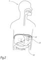
- the implantable system 10 has been schematically represented in the figure 2 when the implantable system 10 is implanted in the body of the patient P.
- the anchor 15 and the implantable device 20 are each implanted in the body of the patient P.
- the anchor 15 is suitable for being fixed in a predetermined position in the stomach 30 of the patient P.
- the anchor 15 is configured to be secured in the upper portion of the stomach 30.
- the anchor 15 is configured to be secured in the gastric fundus of the stomach 30.
- the anchor 15 is intended to be secured as close as possible to the angle of Hiss in the gastric fundus.
- the anchor 15 is configured to be secured in the lower portion of the stomach 30.
- the anchor 15 is configured to support the implantable device 20, preferably in a removable manner.
- the anchor 15 and the implantable device 20 are configured to be fixed to each other, by a fixing device, and the anchor 15 is configured to maintain the implantable device 20 in a fixing position when the anchor 15 is fixed in the stomach 30.
- the anchor 15 comprises a head 35 and a first connector 40.
- the head 35 is configured to anchor the anchor 15 in the predetermined position.
- the head 35 is configured to anchor the anchor 15 to the stomach wall 30.
- the head 35 is, for example, a gastrointestinal clip configured to clamp between two branches of the head 35 a portion of the wall of the stomach 30.
- the head 35 is suitable for being sutured by a thread to the wall of the stomach 30.
- the head 35 is suitable for being buried inside the gastric mucosa after the latter has been dissected.
- the first connector 40 is configured to secure the implantable device 20 to the head 35.
- the implantable device 20 is configured to administer an active substance to the patient P.
- the implantable device 20 is configured to inject an active substance into a body fluid of the patient P.
- the body fluid is, for example, the peritoneal fluid of the patient (parenteral route).
- the body fluid is the blood of the patient P.
- the implantable device 20 is configured to administer the active substance via the enteral route, in particular by release into the stomach.
- an “active substance” is understood to mean a substance having a beneficial effect on the patient's health.
- a drug is an active substance.
- a hormone is another example of an active substance.
- the active substance is, for example, insulin.
- the active substance is a painkiller.
- the active substance is morphine.
- the active substance is levodopa.
- Levodopa or L-dopa, is a drug used in the treatment of Parkinson's disease.
- the active substance is an anticancer drug.
- the active substance is a component of chemotherapy.
- the implantable device 20 comprises a first controller 45, a second connector 50, a power supply 55, a housing 65, a reserve of active substance 67 and an injector 70.
- the first controller 45 is an information processing unit.
- the first controller 45 comprises a first memory 75 and a first processor 80.
- the first controller 45 is produced in the form of a dedicated integrated circuit, or even programmable logic components.
- the first controller 45 comprises a radiofrequency transmitter/receiver.
- a computer program containing program instructions is stored in the first memory 75.
- the program instructions are suitable, when executed by the first processor 80, for implementing a method of administering the active substance to the patient P.
- the first processor 80 is adapted to manipulate and/or transform data represented as electronic or physical quantities in the first memory 75 into other similar data corresponding to physical data in the first memory 75, in registers or other types of display, transmission or storage devices.
- the second connector 50 is configured to cooperate with the first connector 40 to maintain the implantable device 20 in the fixation position.
- the second connector 50 is configured to cooperate with the first connector 40 by snap-fitting.
- the second connector 50 comprises a magnet configured to secure the second connector to the first connector.
- the magnet is, for example, an electromagnet.
- the first connector 40 is configured to be secured to the second connector 50 by screwing.
- the first connector 40 comprises one or preferably two complementary bayonets of fixing holes provided in the second connector 50.
- the second connector 50 is provided so that the implantable device 20 is separable from the anchor 15.
- the second connector 50 is configured so that the implantable device 20 is separable from the anchor 15 when the anchor 15 is fixed in the stomach 30 of the patient P.
- the 55 power supply has been shown on the figure 3 .
- the power supply 55 is configured to supply the first controller 45 with a first supply current C1.
- the power supply 55 is further configured to supply the injector 70 with a second supply current C2.
- the power supply 55 comprises a third connector 85 and a first electrical energy reserve 90.
- the third connector 85 is configured to receive from the first electrical energy reserve 90 the first supply current C1 and the second supply current C2 and to supply the first controller 45 and the injector 70 with, respectively, the first supply current C1 and the second supply current C2.
- the third connector 85 is configured to accommodate the first electrical energy reserve 90.
- the third connector 85 delimits a cavity 95 configured to at least partially accommodate the first electrical energy reserve 90 in a connection position.
- the cavity 95 opens onto the exterior of the housing 65.
- the cavity 95 is configured to allow the insertion of the first electrical energy reserve 90, from the exterior of the housing 65, into the cavity 95.
- the third connector 85 further comprises two first electrical contacts 100, configured to be electrically connected to the first electrical energy reserve 90 when the first electrical energy reserve 90 is in the connection position.
- the two first electrical contacts 100 open into the cavity 95.
- the first electrical energy reserve 90 is configured to store electrical energy.
- the first electrical energy reserve 90 is configured to be charged with electrical energy outside the body of the patient P and to discharge when the first electrical energy reserve 90 is in the connection position.
- the first electrical energy reserve 90 comprises a battery.
- the first electrical energy reserve 90 comprises at least one capacitor or supercapacitor.
- the first electrical energy reserve is configured to supply the first controller 45 with the first supply current C1 when the first electrical energy reserve 90 is in the connection position. Furthermore, the first electrical energy reserve 90 is configured to supply the injector 70 with the second supply current C2 when the first electrical energy reserve 90 is in the connection position.
- the first electrical energy reserve 90 comprises two second electrical contacts 105 complementary to the first electrical contacts 100.
- the first reserve of electrical energy 90 can be provided to be swallowed by the patient P.
- the first energy reserve 90 is capable of being replaced by endoscopy.
- the first electrical energy reserve 90 has a volume strictly less than 6 milliliters (ml).
- the first electrical energy reserve 90 further has three dimensions each measured in a respective direction, each direction being perpendicular to the other two directions, and each dimension is strictly less than 5 centimeters (cm).
- the first electrical energy reserve 90 is movable between the connection position and a disconnection position.
- the first electrical energy reserve 90 is received in the stomach 30 of the patient P but is not electrically connected to the third connector 85.
- the first electrical energy reserve 90 is completely extracted from the cavity 95.
- the first electrical energy reserve 90 is configured to spontaneously move from the disconnection position to the connection position.
- the first electrical energy reserve 90 comprises attractors 110.
- the attractors 110 are configured to exert on the first electrical energy reserve 90, when the first electrical energy reserve 90 is in the disconnected position, a force tending to move the first electrical energy reserve 90 from the disconnected position to the connected position.
- the attractors 110 are configured to maintain the first electrical energy reserve 90 in the connection position.
- the attractors 110 comprise, for example, a first magnet capable of cooperating with a second magnet 112 of the third connector 85.
- the first magnet is capable of cooperating with a ferromagnetic portion of the third connector 85.
- the first magnet and the second magnet 112 are, for example, electromagnets.
- the housing 65 is configured to isolate the first controller 45 from the exterior of the housing 65.
- the housing 65 defines a chamber accommodating at least the first controller 45 and the injector 70.
- the active substance reserve 67 is configured to store the active substance and to transmit the active substance to the injector 70.
- the active substance reserve 67 comprises, for example, a connector secured to the housing 65 and a capsule containing the active substance.
- the capsule is suitable for being swallowed by the patient P and for connecting to the connector to deliver the active substance to the injector.
- each capsule is configured to eject an empty capsule from the corresponding connector.
- the injector 70 is suitable for injecting the active substance into an organ C of the patient P.
- the injector 70 comprises a pump and a first catheter 114.
- the pump is configured to draw active substance from active substance reservoir 67 and to deliver active substance to first catheter 114.
- a peristaltic pump is an example of a pump that may be integrated into the injector 70.
- the device comprises only a single first catheter.
- the first catheter 114 has a first end and a second end. The first end is connected to the pump. The second end is adapted to administer to the patient P the active substance received from the pump.
- the injector 70 is adapted to inject the active substance into the peritoneal fluid of the patient P.
- the active substance can pass from the peritoneal fluid to the blood system of the patient P.
- the second end opens into a blood vessel (vein or artery) of the patient P.
- the second end opens into the digestive tract of patient P.
- the second end opens into a lumen of the intestine of patient P.
- the second end opens into the stomach of patient P.
- the first electrical energy reserve 90 is charged with electrical energy.
- the first electrical energy reserve 90 therefore generates the first supply current C1 intended for the first controller 45.
- the anchor 15, the implantable device 20 and the second device 25 are implanted in the body of the patient P.
- an activation message is transmitted, by an external device, to the implantable device 20.
- the activation message is transmitted by radiofrequency communication.
- the activation message informs the first controller 45 that the implantable system 10 has been successfully implanted in the body of the patient P.
- the active substance is administered to patient P.
- the first controller 45 controls the administration of a quantity of active substance to the patient P, by the injector 70, with an administration frequency.
- the amount of active substance administered and the frequency of administration are predetermined.
- the implantable device 20 makes it possible to deliver active substances, either enterally or parenterally.
- the implantable device 20 therefore makes it possible to deliver, in a simple and painless manner for the patient P, active substances which are usually injected, for example intravenously or intramuscularly.
- the implantable device 20 also makes it possible to automatically and regularly deliver active substances, for example in the case where arrival in the intestine must be at as constant a flow rate as possible, such as L-Dopa for certain Parkinsonian patients. Thanks to the device 20, the administration of the active substance is facilitated. Indeed, the capsule containing the active substance can be administered to the patient orally, which is therefore not very painful and not very restrictive for the patient. In particular, the number of capsules of active substance to be swallowed is much lower than the number of doses of medication to be taken, over the same period, to achieve the same administration rate if the medications are administered in the form of conventional pills.
- the implantable device 20 once it is installed, is not very restrictive for the patient P.
- the implantable device 20 is capable of replacing external perfusions, but does not constitute, like the latter, an obstacle to the patient's movement.
- the implantable device 20 is in the stomach, replacement of the first electrical energy reserve 90 is easy and can, for example, be carried out by endoscopically from the esophagus, in a simple and rapid manner. In addition, the replacement of the first electrical energy reserve 90 poses little risk of infection since no incision is made.
- Attractors 110 makes it even simpler to set up the first reserve of electrical energy 90, even without endoscopy, since it is then sufficient for the patient P to swallow the first reserve of electrical energy 90.
- the implantable system 10 does not assume that the patient P permanently wears means for storing electrical energy outside his body, nor that unsightly electrical conductors emerge outside the body of the patient P.
- the implantable system 10 is therefore not very restrictive for the patient.
- the implantable device 20 comprises at least one sensor. Each sensor is capable of measuring a value of a parameter representative of a physiological phenomenon of the patient P.
- a parameter is, for example, a level of a biological marker in a body fluid F of patient P.
- the implantable device 20 then comprises a second catheter configured to conduct a bodily fluid F of the patient P from the organ C to the sensor.
- a bodily fluid F of the patient P is the peritoneum
- the fluid F is the peritoneal fluid.
- the biological marker is, for example, glucose.
- the biological marker is an ion present in the body fluid F.
- the sensor is then suitable for measuring a level of the biological marker in the body fluid F.
- the sensor is suitable for measuring a level of glucose.
- the first controller 45 is configured to control the injection of the active substance, by the injector 70, according to at least one value of the measured parameter.
- the first controller 45 is capable of modifying a period or a frequency of administration of the active substance and/or a dose of active substance to be administered to the patient according to the measured values.
- the senor measures values of the parameter with a predetermined measurement period
- the first controller 45 controls the administration of the active substance, by the injector 70, according to the measured values.
- the first controller 45 compares the values of the measured parameter to a predetermined threshold and controls the administration of a dose of active substance if one or more measured values are greater than or equal to the predetermined threshold.
- the dose of active substance administered is, for example, a dose corresponding to a predetermined volume.
- the first controller 45 controls the administration of a dose of active substance with a predetermined administration period, each dose administered corresponding to a volume of active substance calculated according to the measured values.
- the senor is separate from the implantable device 20.
- the implantable system 10 comprises an additional device capable of being implanted in the body of the patient P and of communicating by radiofrequency communication with the implantable device 20.
- the sensor is then integrated into the additional device.
- the additional device is configured to transmit the measured values to the implantable device 20 by radiofrequency communication.
- the additional device comprises a second controller comprising a second memory and a second processor and capable of controlling the acquisition of parameter values by the sensor as well as the emission of radiofrequency messages for transmitting the measured values to the implantable device 20.
- the power supply 55 does not include a third connector 85 or an electrical energy reserve 90.
- the power supply 55 includes an electrical energy generator.
- electrical energy generator is meant that the electrical energy generator is not configured to be charged with electrical energy by an electric current.
- the electrical energy generator is capable of generating at least one electrical current by reaction of at least one chemical species present in the body of the patient P. More precisely, the electrical energy generator is capable of generating the first supply current C1 and the second supply current C2.
- the electrical energy generator comprises two electrodes, the electrodes bathing in the gastric juices of the patient P when the centralizing device 20 is in the fixing position.
- the electrodes of the generator of electrical energy are provided to bathe in the intestine of the patient P when the centralizing device 20 is in the fixing position.
- Each electrode comprises at least one enzyme.
- each electrode comprises at least one microorganism.
- each electrode of the electrical energy generator comprises an electrical conductor covered with the enzyme or microorganism, the assembly thus formed being surrounded by a membrane.
- the membrane is, for example, configured to be crossed by certain chemical species naturally present in the stomach or intestine of the patient P.
- one of the electrodes of the electrical energy generator When the electrodes of the electrical energy generator are immersed in gastric juices or in intestinal fluid, one of the electrodes acts as an anode in an oxidation-reduction reaction involving a first chemical species. Simultaneously, the other electrode acts as a cathode in an oxidation-reduction reaction involving a second chemical species.
- the first chemical species is, for example, glucose.
- the second chemical species is, for example, oxygen.
- the first chemical species is, for example, glucose.
- the second chemical species is, for example, oxygen.
- the third example of an implantable system 10 does not require electrically charging an electrical energy store 90 or causing the electrical energy store 90 to enter the body of the patient P.
- the electrical energy generator is capable of generating at least one electric current by converting mechanical energy into electrical energy.
- the electrical energy generator is capable of generating at least one electric current from the movements of the stomach 30.
- the anchor 15 and the implantable device 20 form two separate devices.
- the implantable device 20 and the anchor 15 are capable of form a single device, the anchor 15 and the implantable device 20 then not being separable from each other.
- the anchor 15 is integral with the housing 65 of the implantable device 20.
- the injector 70 comprises two first catheters 114.
- the pump is configured to aspirate through a first catheter 114 a body fluid F, and to discharge through the other catheter 114 the aspirated body fluid F.
- the pump is further configured to inject the active substance into the body fluid F such that the discharged fluid F is loaded with the active substance.
- each first catheter 114 passes through the wall of the stomach 30 to open between the parietal layer and the visceral layer of the peritoneum.
- the second end of each first catheter 114 opens between the parietal layer and the visceral layer of the peritoneum.
- each first catheter 114 may in particular have a length of between 1 centimeter (cm) and 20 cm, for example between 2 cm and 15 cm, in particular between 6 cm and 12 cm.
- Each first catheter 114 may have a diameter less than or equal to 3 millimeters (mm), for example less than or equal to 2 mm.
- the implantable device 20 comprises two first catheters 114
- one of the first catheters 114 fulfills the role of second catheter.
- the administration method comprises an aspiration step, an injection step and an expulsion step.
- a flow of body fluid F is sucked by one of the first catheters 114.
- the first controller 45 controls the suction of the body fluid F by the pump.
- a dose of the active substance is injected by the pump into the body fluid flow F.
- the first controller 45 controls the injection by the pump of the active substance into the body fluid flow F.
- the body fluid F containing the active substance is discharged by the other first catheter 114.
- the body fluid F containing the active substance is discharged into the same organ or cavity of the patient P from which the body fluid F was aspirated. The active substance is thus administered into the body fluid F of the patient P.
- the first two catheters 114 open into the peritoneum, for example between the visceral layer and the parietal layer of the peritoneum.
- the body fluid F is then the peritoneal fluid.
- first two catheters 114 are likely to open into other organs of the patient P.
- the first two catheters 114 each open into a blood vessel of the patient P.
- the bodily fluid F is then blood.
- a continuous flow of body fluid F is aspirated by one of the first catheters 114, receives the active substance and is discharged by the other first catheter 114.
- the suction, injection and expulsion steps are implemented continuously over an extended period of time, for example a period of time greater than or equal to one hour, greater than or equal to one day, or greater than or equal to one week.
- the suction, injection and expulsion steps are implemented in a split manner, in particular with a frequency determined by the first controller 45.
- the frequency is, for example, determined by the first controller 45 from the values of the parameter measured by the sensor.
- a flow of body fluid F is aspirated by one of the first catheters 114 and discharged by the other first catheter 114 without an active substance being injected into the body fluid F.
- the flow of body fluid then expels from the first catheter 114 through which the flow is discharged particles, agglomerates or other solid elements, which would have penetrated, or would have formed, in the lumen of the first catheter 114.
- This step is, for example, then repeated by reversing the first catheter 114 through which the flow is discharged and the first catheter 114 through which the flow is aspirated.
- the cleaning step comprises injecting through each first catheter 114 an enzyme capable of dissolving fibrinous formations or clots which may have formed in the catheter(s) 114.
- Urokinase and streptokinase are examples of enzymes.
- the enzyme injection is, for example, performed at least once a month, for example at least once a week. According to one embodiment, the enzyme injection is performed once a day.
- the enzyme is, in particular, stored in an enzyme reserve integrated into the implantable device 20.
- the discharge of the active substance from the first catheter 114 is facilitated by the flow of body fluid F.
- the entire active substance injected by the pump is efficiently discharged from the first catheter 114 even if the amount of active substance is very small and would otherwise risk remaining partially inside the first catheter, or if the body fluid F into which the active substance is discharged exerts a pressure capable of preventing the exit of the active substance from the first catheter 114.
- the injection regulation is therefore more efficient, since very small quantities of active substance can be administered to the patient with great precision.
- This arrangement of the invention in fact allows an advantageous regulated dilution of the active substance.
- the flow of bodily fluid F discharged by the first catheter 114 makes it possible to unblock a first catheter 114 which would be partially or totally blocked, during the active substance injection step or a cleaning step.
- Each first catheter 114 is made of a biocompatible material.
- the biocompatible material is for example chosen from polyurethanes, silicone, nylons, polycarbonate resins or polysulfones.
- Each first catheter 114 is, for example, made of a porous material.
- the porous material is configured to be traversed at least by the active substance.
- the porous material is configured to be traversed by the active substance and by the body fluid F.
- Polyvinyl alcohol (also referred to as PVA) is an example of a porous material suitable for forming a first catheter 114.
- the porous material is a naturally non-porous material but in which perforations have been made. The perforations then act as pores.
- Embodiments in which the second end is open, i.e., where the central lumen of the first catheter 114 opens to the exterior of the first catheter 114 are conceivable, as are embodiments in which the second end is closed.
- the body fluid F is sucked partly through the second end and partly through the pores or perforations of the porous material.
- the active substance, and where appropriate the sucked body fluid F are discharged partly through the second end and partly through the pores or perforations of the porous material.
- each first catheter 114 When the second end of each first catheter 114 is closed, the active substance, and if applicable the body fluid F, are exchanged between the first catheter 114 and the patient's body through the pores or perforations of the first catheter 114.
- the choice of a porous material for the first catheter(s) 114 allows suction and/or expulsion of liquid through the pores, over the entire length of the first catheter 114 concerned.
- the first catheter(s) 114 are then less sensitive to a possible obstruction of the catheter lumen.
- the active substance is distributed over a larger area of the body of the patient P than if the active substance were expelled only through the second end. Possible side effects dependent on the volume density of active substance are therefore limited.
- each first catheter 114 comprises a support element capable of coming to bear against the external wall of the stomach 30 or against the visceral layer of the peritoneum.
- the support element is, for example, configured to, when it is bearing against the external wall of the stomach 30 or against the visceral layer of the peritoneum, exert a force tending to bring the implantable device 20 closer to the wall interior of the stomach 30, in particular to press the implantable device 20 against the interior wall of the stomach 30.
- the first catheter(s) 114 act as an anchor 15 to secure the implantable device 20 to the stomach wall 30.
- each first catheter 114 is fixed to the stomach wall by means of stitches jointly passing through the wall of the stomach 30 and the first catheter 114.
- each first catheter 114 carries, for example, at least one wire or tie capable of being fixed to the wall of the stomach 30.
- the implantable device 20 is at least partially embedded within the stomach mucosa.
- the implantable device 20 is placed between the stomach mucosa and the stomach muscularis.
- the implantable device 20 is placed between the stomach mucosa and the stomach submucosa.
- the head 35 comprises at least one sole located outside the stomach 30.
- the head 35 comprises two soles.
- Each sole is configured to come to bear against the outer face of the wall of the stomach 30 and to be connected to the implantable device 20 so as to exert a force tending to press the implantable device 20 against the inner face of the wall of the stomach 30.
- each sole is configured to be placed between the visceral layer and the parietal layer of the peritoneum and to come to bear against the visceral layer to press the implantable device 20 against the inner face of the wall of the stomach 30.
- each sole is, for example, a plate.
- each sole comprises a lattice of wires stretched over a frame, in particular a flexible frame suitable for being folded and inserted into an endoscope or a hollow needle.
- the first connector 40 comprises, for example, one or more rings secured to the housing 65.
- Each sole is, for example, fixed to the implantable device 20 by one or more wires fixed to one or more of the rings.
- Fixation by one or more soles makes it possible to distribute the pressure exerted by the implantable device over a larger surface area of the stomach wall 30 and therefore to reduce the force thus exerted. Furthermore, this method of fixation does not involve generating a fold in the stomach wall that reduces the volume of the stomach, which is likely to generate tensions in the anchor fixed there. Since the forces exerted on the stomach wall are reduced, the risks of an inflammatory reaction of the gastric mucosa occurring are limited.
Landscapes
- Health & Medical Sciences (AREA)
- Life Sciences & Earth Sciences (AREA)
- Engineering & Computer Science (AREA)
- Public Health (AREA)
- Animal Behavior & Ethology (AREA)
- Veterinary Medicine (AREA)
- Biomedical Technology (AREA)
- Heart & Thoracic Surgery (AREA)
- General Health & Medical Sciences (AREA)
- Physics & Mathematics (AREA)
- Surgery (AREA)
- Pathology (AREA)
- Molecular Biology (AREA)
- Medical Informatics (AREA)
- Biophysics (AREA)
- Hematology (AREA)
- Anesthesiology (AREA)
- Optics & Photonics (AREA)
- Bioinformatics & Cheminformatics (AREA)
- Chemical & Material Sciences (AREA)
- Medicinal Chemistry (AREA)
- Vascular Medicine (AREA)
- Emergency Medicine (AREA)
- Infusion, Injection, And Reservoir Apparatuses (AREA)
- Media Introduction/Drainage Providing Device (AREA)
- Medicinal Preparation (AREA)
Description
- La présente invention concerne un dispositif implantable. La présente invention concerne également un procédé d'administration d'une substance active à un patient.
- Des dispositifs implantés dans le corps sont utilisés pour administrer des médicaments à des patients. Les dispositifs implantés comprennent alors une batterie et une réserve de médicament. Cependant, il est nécessaire de recharger ou de remplacer régulièrement les batteries et les réserves de tels dispositifs implantés. En particulier, dans de nombreux cas ce remplacement est effectué par une opération chirurgicale. Une telle procédure est relativement chère et contraignante pour le patient puisqu'elle a lieu dans un bloc opératoire d'un établissement hospitalier et qu'une anesthésie est nécessaire, ainsi qu'un séjour prolongé dans l'établissement hospitalier afin de surveiller les suites de l'opération. En outre, comme pour toute intervention chirurgicale, il existe des risques que le patient contracte une infection lors de l'opération.
- Dans d'autres cas, des dispositifs implantés du type précité sont alimentés depuis l'extérieur par un module de stockage d'énergie qui est porté par le patient à l'extérieur de son corps. Par exemple, il arrive que des dispositifs d'alimentation transmettent de l'énergie par ondes ultrasonores au dispositif de stimulation, à travers la peau et la cage thoracique du patient. Cependant, les ondes ultrasonores traversent mal les os, et une grande précision dans le placement de la source d'ultra-sons est alors nécessaire, dans les cas où le dispositif implanté est situé devant la cage thoracique, afin d'assurer une bonne alimentation du dispositif implanté. En outre, un tel dispositif d'alimentation extérieur au corps du patient est disgracieux.
- Il arrive également que des dispositifs implantables soient équipés de connecteurs filaires, permettant une connexion électrique ou un transfert de fluide entre le dispositif implantable et un dispositif extérieur. Par ce biais, un courant électrique d'alimentation ou un flux de médicament sont échangés avec le dispositif extérieur. Là encore, ces connecteurs débouchant à travers la peau du patient sont disgracieux, et présentent nécessairement des risques sanitaires ainsi que des contraintes importantes pour le patient dans sa vie de tous les jours.
- Il existe donc un besoin pour un système implantable qui soit moins contraignant pour le patient.
- Il est connu du document
WO 02/087657 A2
documentEP 1504 778 A2 divulgue un dispositif de délivrance de substance active dans le tractus gastro-intestinal, visant à induire la satiété chez un patient. Le documentWO 2006/035446 A2 divulgue un dispositif implantable pour détecter un changement physiologique associé à l'ingestion d'aliments ou à la faim, et comprenant un mécanisme adapté pour stimuler directement une région par une substance active propre à déclencher la satiété. - Il est proposé un dispositif implantable propre à être fixé dans une position de fixation à une paroi de l'estomac d'un patient, le dispositif implantable étant accueilli dans l'estomac lorsque le dispositif implantable est dans la position de fixation, le dispositif implantable comprenant une réserve d'une substance active et un injecteur propre à administrer la substance active au patient, le dispositif implantable étant caractérisé en ce que l'injecteur comporte deux cathéters, l'injecteur étant configuré pour administrer la substance active dans un fluide corporel du patient à travers au moins un des cathéters, l'injecteur étant configuré pour aspirer, par l'un des cathéters le fluide corporel du patient et pour rejeter par l'autre cathéter le fluide corporel aspiré.
- Selon des modes de réalisation, le dispositif implantable comprend l'une ou plusieurs des caractéristiques suivantes, prises isolément ou suivant toutes les combinaisons techniquement possibles :
- l'injecteur est configuré pour injecter la substance active dans un fluide corporel du patient ;
- le fluide corporel est le liquide péritonéal ou le sang ;
- l'injecteur est configuré pour injecter la substance active dans le tube digestif du patient ;
- l'injecteur comporte au moins un cathéter propre à permettre l'injection de la substance active, par l'injecteur, dans une lumière de l'intestin du patient ;
- la substance active est choisie parmi l'ensemble formé de l'insuline, la levodopa, un antidouleur et un anticancéreux ;
- le dispositif implantable est propre à être fixé dans la partie supérieure de l'estomac ;
- la réserve de substance active comprend un connecteur solidaire de l'injecteur et une capsule contenant la substance active, la capsule étant propre à être avalée par le patient et à venir se connecter au connecteur pour délivrer la substance active à l'injecteur ;
- le dispositif implantable comprend un capteur et au moins un cathéter propre à conduire un fluide corporel du patient au capteur, le capteur étant propre à mesurer au moins une valeur d'un taux d'un marqueur biologique dans le fluide corporel ;
- le dispositif implantable comprend en outre un contrôleur propre à commander l'administration, par l'injecteur, de la substance active en fonction d'au moins une valeur du taux mesurée ;
- le contrôleur est propre à calculer une fréquence et/ou une dose de substance active à administrer au patient en fonction d'au moins une valeur du taux mesurée ;
- le fluide corporel est le liquide péritonéal ou le sang ;
- le dispositif implantable comprend une alimentation électrique comportant une réserve d'énergie électrique amovible et un connecteur propre à accueillir la réserve d'énergie électrique, la réserve d'énergie électrique étant propre à alimenter électriquement l'injecteur lorsque la réserve d'énergie électrique est connectée électriquement au connecteur dans une position de connexion et de préférence étant configurée pour être avalée par le patient et pour se déplacer spontanément jusqu'à la position de connexion depuis une position de déconnexion dans laquelle la réserve d'énergie électrique est accueillie dans l'estomac du patient et est déconnectée du connecteur ;
- le dispositif implantable comprend une alimentation électrique propre à générer un courant électrique d'alimentation de l'injecteur par réaction d'au moins une espèce chimique présente dans le corps du patient, notamment le glucose ;
- le dispositif implantable comprend une alimentation électrique propre à générer un courant électrique d'alimentation de l'injecteur par conversion d'énergie mécanique en énergie électrique.
- Le dispositif implantable comprend deux premiers cathéters. Les deux premiers cathéters peuvent être raccordés, par l'intermédiaire de la pompe, pour former une continuité fluidique. Un premier cathéter peut être relié à l'aspiration de la pompe, et le deuxième au refoulement. Aspiration et refoulement du liquide corporel sont assurés par la pompe.
- Des caractéristiques et avantages de l'invention apparaîtront à la lecture de la description qui va suivre, donnée uniquement à titre d'exemple non limitatif et faite en référence aux dessins annexés, sur lesquels :
- la
figure 1 est un schéma d'un exemple de système implantable comportant une alimentation électrique, - la
figure 2 est une représentation schématique du dispositif implantable de lafigure 1 , implanté dans le corps d'un patient, et - la
figure 3 est une représentation schématique de l'alimentation de lafigure 1 . - Un premier exemple de système implantable 10 est représenté à la
figure 1 . - Le système implantable 10 comporte une ancre 15 et un dispositif implantable 20.
- Il est entendu par « système implantable » qu'au moins un élément parmi la liste formée de l'ancre 15 et du dispositif implantable 20 est prévu pour être implanté dans le corps humain.
- En particulier, il est entendu par « implantable » qu'au moins un élément parmi l'ancre 15 et le dispositif implantable 20 est prévu pour séjourner dans le corps d'un patient P pendant une durée strictement supérieure à une semaine, de préférence strictement supérieure à un mois, de préférence supérieure ou égale à un an.
- Le système implantable 10 a été représenté schématiquement sur la
figure 2 lorsque le système implantable 10 est implanté dans le corps du patient P. - Selon l'exemple de la
figure 2 , l'ancre 15 et le dispositif implantable 20 sont chacun implanté dans le corps du patient P. - L'ancre 15 est propre à être fixée dans une position prédéterminée dans l'estomac 30 du patient P.
- Par exemple, l'ancre 15 est configurée pour être fixée dans la partie supérieure de l'estomac 30. En particulier, l'ancre 15 est configurée pour être fixée dans le fundus gastrique de l'estomac 30. Par exemple, l'ancre 15 est prévue pour être fixée le plus près possible de l'angle de Hiss dans le fundus gastrique.
- En variante, l'ancre 15 est configurée pour être fixée dans la partie inférieure de l'estomac 30.
- L'ancre 15 est configurée pour supporter le dispositif implantable 20, de préférence de manière amovible. En particulier, l'ancre 15 et le dispositif implantable 20 sont configurés pour être fixés l'un à l'autre, par un dispositif de fixation, et l'ancre 15 est configurée pour maintenir le dispositif implantable 20 dans une position de fixation lorsque l'ancre 15 est fixée dans l'estomac 30.
- L'ancre 15 comporte une tête 35 et un premier connecteur 40.
- La tête 35 est configurée pour ancrer l'ancre 15 dans la position prédéterminée. En particulier, la tête 35 est configurée pour ancrer l'ancre 15 à la paroi de l'estomac 30.
- La tête 35 est, par exemple, un clip gastro-intestinal configuré pour enserrer entre deux branches de la tête 35 une portion de la paroi de l'estomac 30.
- En variante, la tête 35 est propre à être suturée par un fil à la paroi de l'estomac 30.
- Selon une autre variante, la tête 35 est propre à être enfouie à l'intérieur de la muqueuse gastrique après que celle-ci ait été disséquée.
- Le premier connecteur 40 est configuré pour fixer le dispositif implantable 20 à la tête 35.
- Le dispositif implantable 20 est configuré pour administrer une substance active au patient P.
- Par exemple, le dispositif implantable 20 est configuré pour injecter une substance active dans un fluide corporel du patient P. Le fluide corporel est, par exemple, le liquide péritonéal du patient (voie parentérale). En variante, le fluide corporel est le sang du patient P.
- En variante, le dispositif implantable 20 est configuré pour administrer la substance active par la voie entérale, notamment par libération dans l'estomac.
- Il est entendu par « substance active » une substance ayant un effet favorable sur la santé du patient.
- Par exemple, un médicament est une substance active. Une hormone est un autre exemple de substance active.
- La substance active est, par exemple, l'insuline.
- En variante, la substance active est un antidouleur. Par exemple, la substance active est la morphine.
- Selon une autre variante, la substance active est la levodopa. La levodopa, ou L-dopa, est un médicament utilisé dans le traitement de la maladie de Parkinson.
- Selon une autre variante, la substance active est un médicament anticancéreux. Par exemple, la substance active est un composant d'une chimiothérapie.
- Le dispositif implantable 20 comporte un premier contrôleur 45, un deuxième connecteur 50, une alimentation électrique 55, un boîtier 65, une réserve de substance active 67 et un injecteur 70.
- Le premier contrôleur 45 est une unité de traitement d'informations. Le premier contrôleur 45 comporte une première mémoire 75 et un premier processeur 80.
- En variante, le premier contrôleur 45 est réalisé sous forme de circuit intégré dédié, ou encore de composants logiques programmables.
- Selon un mode de réalisation, le premier contrôleur 45 comporte un émetteur/récepteur radiofréquence.
- Un programme d'ordinateur contenant des instructions de programme est mémorisé dans la première mémoire 75. Les instructions de programme sont propres, lorsqu'elles sont exécutées par le premier processeur 80, à mettre en oeuvre un procédé d'administration de la substance active au patient P.
- Le premier processeur 80 est propre à manipuler et/ou transformer des données représentées comme des quantités électroniques ou physiques dans la première mémoire 75 en d'autres données similaires correspondant à des données physiques dans la première mémoire 75, dans des registres ou d'autres types de dispositifs d'affichage, de transmission ou de mémorisation.
- Le deuxième connecteur 50 est configuré pour coopérer avec le premier connecteur 40 pour maintenir le dispositif implantable 20 dans la position de fixation.
- Par exemple, le deuxième connecteur 50 est configuré pour coopérer avec le premier connecteur 40 par encliquetage.
- En variante, le deuxième connecteur 50 comporte un aimant configuré pour fixer le deuxième connecteur au premier connecteur. L'aimant est, par exemple, un électroaimant.
- Selon une autre variante, le premier connecteur 40 est configuré pour être solidarisé au deuxième connecteur 50 par vissage. En variante, le premier connecteur 40 comporte une ou de préférence deux baïonnettes complémentaires d'orifices de fixation ménagés dans le deuxième connecteur 50.
- De préférence, le deuxième connecteur 50 est prévu pour que le dispositif implantable 20 soit séparable de l'ancre 15. En particulier, le deuxième connecteur 50 est configuré pour que le dispositif implantable 20 soit séparable de l'ancre 15 lorsque l'ancre 15 est fixée dans l'estomac 30 du patient P.
- L'alimentation électrique 55 a été représentée sur la
figure 3 . - L'alimentation électrique 55 est configurée pour alimenter le premier contrôleur 45 avec un premier courant d'alimentation C1.
- L'alimentation électrique 55 est, en outre, configurée pour alimenter l'injecteur 70 avec un deuxième courant d'alimentation C2.
- L'alimentation électrique 55 comporte un troisième connecteur 85 et une première réserve d'énergie électrique 90.
- Le troisième connecteur 85 est configuré pour recevoir de la première réserve d'énergie électrique 90 le premier courant d'alimentation C1 et le deuxième courant d'alimentation C2 et pour alimenter le premier contrôleur 45 et l'injecteur 70 avec, respectivement, le premier courant d'alimentation C1 et le deuxième courant d'alimentation C2.
- Le troisième connecteur 85 est configuré pour accueillir la première réserve d'énergie électrique 90. En particulier, le troisième connecteur 85 délimite une cavité 95 configurée pour accueillir au moins partiellement la première réserve d'énergie électrique 90 dans une position de connexion.
- Selon l'exemple de la
figure 3 , la cavité 95 débouche sur l'extérieur du boîtier 65. En particulier, la cavité 95 est configurée pour permettre l'insertion de la première réserve d'énergie électrique 90, depuis l'extérieur du boîtier 65, dans la cavité 95. - Le troisième connecteur 85 comporte, en outre, deux premiers contacts électriques 100, configurés pour être connectés électriquement à la première réserve d'énergie électrique 90 lorsque la première réserve d'énergie électrique 90 est dans la position de connexion. En particulier, les deux premiers contacts électriques 100 débouchent à l'intérieur de la cavité 95.
- La première réserve d'énergie électrique 90 est configurée pour stocker de l'énergie électrique. En particulier, la première réserve d'énergie électrique 90 est configurée pour être chargée en énergie électrique à l'extérieur du corps du patient P et pour se décharger lorsque la première réserve d'énergie électrique 90 est dans la position de connexion. Par exemple, la première réserve d'énergie électrique 90 comporte une batterie. En variante, la première réserve d'énergie électrique 90 comporte au moins un capaciteur ou une supercapacité.
- La première réserve d'énergie électrique est configurée pour alimenter le premier contrôleur 45 avec le premier courant d'alimentation C1 lorsque la première réserve d'énergie électrique 90 est dans la position de connexion. En outre, la première réserve d'énergie électrique 90 est configurée pour alimenter l'injecteur 70 avec le deuxième courant d'alimentation C2 lorsque la première réserve d'énergie électrique 90 est dans la position de connexion.
- Selon l'exemple de la
figure 3 , la première réserve d'énergie électrique 90 comporte deux deuxièmes contacts électriques 105 complémentaires des premiers contacts électriques 100. - La première réserve d'énergie électrique 90 peut être prévue pour être avalée par le patient P.
- Selon une variante, la première réserve d'énergie 90 est propre à être remplacée par endoscopie.
- En particulier, la première réserve d'énergie électrique 90 présente un volume strictement inférieur à 6 millilitres (ml).
- La première réserve d'énergie électrique 90 présente, en outre, trois dimensions mesurées chacune selon une direction respective, chaque direction étant perpendiculaire aux deux autres directions, et chaque dimension est strictement inférieure à 5 centimètres (cm).
- La première réserve d'énergie électrique 90 est mobile entre la position de connexion et une position de déconnexion. Lorsque la première réserve d'énergie électrique 90 est dans la position de déconnexion, la première réserve d'énergie électrique 90 est accueillie dans l'estomac 30 du patient P mais n'est pas connectée électriquement au troisième connecteur 85. Par exemple, lorsque la première réserve d'énergie électrique 90 est dans la position de déconnexion, la première réserve d'énergie électrique est totalement extraite de la cavité 95.
- La première réserve d'énergie électrique 90 est configurée pour se déplacer spontanément depuis la position de déconnexion vers la position de connexion. Par exemple, la première réserve d'énergie électrique 90 comporte des attracteurs 110.
- Les attracteurs 110 sont configurés pour exercer sur la première réserve d'énergie électrique 90, lorsque la première réserve d'énergie électrique 90 est dans la position de déconnexion, une force tendant à déplacer la première réserve d'énergie électrique 90 depuis la position de déconnexion vers la position de connexion.
- En outre, les attracteurs 110 sont configurés pour maintenir la première réserve d'énergie électrique 90 dans la position de connexion.
- Les attracteurs 110 comportent, par exemple, un premier aimant propre à coopérer avec un deuxième aimant 112 du troisième connecteur 85. En variante, le premier aimant est propre à coopérer avec une portion ferromagnétique du troisième connecteur 85. Le premier aimant et le deuxième aimant 112 sont, par exemple, des électro-aimants.
- Le boîtier 65 est configuré pour isoler le premier contrôleur 45 de l'extérieur du boîtier 65. Par exemple, le boîtier 65 délimite une chambre accueillant au moins le premier contrôleur 45 et l'injecteur 70.
- La réserve de substance active 67 est configurée pour stocker la substance active et pour transmettre la substance active à l'injecteur 70.
- La réserve de substance active 67 comporte, par exemple, un connecteur solidaire du boîtier 65 et une capsule contenant la substance active. La capsule est propre à être avalée par le patient P et à venir se connecter au connecteur pour délivrer la substance active à l'injecteur. En particulier, chaque capsule est configurée pour éjecter du connecteur correspondant une capsule vide.
- L'injecteur 70 est propre à injecter la substance active dans un organe C du patient P. Par exemple, l'injecteur 70 comporte une pompe et un premier cathéter 114.
- La pompe est configurée pour prélever la substance active dans la réserve de substance active 67 et pour transmettre la substance active au premier cathéter 114.
- Une pompe péristaltique est un exemple de pompe susceptible d'être intégrée à l'injecteur 70.
- Selon un exemple, non couvert par les revendications, le dispositif ne comprend qu'un seul premier cathéter. Le premier cathéter 114 présente une première extrémité et une deuxième extrémité. La première extrémité est connectée à la pompe. La deuxième extrémité est propre à administrer au patient P la substance active reçue de la pompe.
- Lorsque le fluide corporel F est le liquide péritonéal, la deuxième extrémité débouche dans le péritoine, et l'injecteur 70 est propre à injecter la substance active dans le liquide péritonéal du patient P. La substance active peut passer du liquide péritonéal au système sanguin du patient P.
- En variante, lorsque le fluide corporel F est le sang, la deuxième extrémité débouche dans un vaisseau sanguin (veine ou artère) du patient P.
- Dans la variante entérale, la deuxième extrémité débouche dans le tube digestif du patient P. Par exemple, la deuxième extrémité débouche dans une lumière de l'intestin du patient P. En variante, la deuxième extrémité débouche dans l'estomac du patient P.
- Le fonctionnement du système implantable 10 va maintenant être décrit.
- Au cours d'une première étape préalable à l'implantation de l'ancre 15, du dispositif implantable 20 et du deuxième dispositif 25 dans le corps du patient P, la première réserve d'énergie électrique 90 est chargée en énergie électrique. La première réserve d'énergie électrique 90 génère donc le premier courant d'alimentation C1 à destination du premier contrôleur 45.
- Au cours d'une deuxième étape, l'ancre 15, le dispositif implantable 20 et le deuxième dispositif 25 sont implantés dans le corps du patient P.
- Au cours d'une troisième étape, un message d'activation est transmis, par un dispositif externe, au dispositif implantable 20. En particulier, le message d'activation est transmis par communication radiofréquence. Le message d'activation informe le premier contrôleur 45 que le système implantable 10 a bien été implanté dans le corps du patient P.
- Au cours d'une quatrième étape, la substance active est administrée au patient P.
- Le premier contrôleur 45 commande l'administration d'une quantité de substance active au patient P, par l'injecteur 70, avec une fréquence d'administration.
- Par exemple, la quantité de substance active administrée et la fréquence d'administration sont prédéterminées.
- Le dispositif implantable 20 permet de délivrer des substances actives, soit par voie entérale, soit par voie parentérale. Le dispositif implantable 20 permet donc de délivrer de manière simple et non douloureuse pour le patient P des substances actives qui sont habituellement injectées, par exemple par voie intraveineuse ou intramusculaire.
- Le dispositif implantable 20 permet également de délivrer de manière automatique et régulière des substances actives, par exemple dans le cas où l'arrivée dans l'intestin doit impérativement se faire à un débit aussi constant que possible, telle que la L-Dopa pour certains patients Parkinsoniens. Grâce au dispositif 20, l'administration de la substance active est facilitée. En effet, la capsule contenant la substance active peut être administrée au patient par voie orale, ce qui est donc peu douloureux et peu contraignant pour le patient. En particulier, le nombre de capsules de substance active à avaler est bien inférieur au nombre de prises de médicament à effectuer, sur une même période, pour arriver au même débit d'administration si les médicaments sont administrés sous forme de pilules classiques.
- En outre, le dispositif implantable 20, une fois qu'il est installé, est peu contraignant pour le patient P. En particulier, le dispositif implantable 20 est susceptible de remplacer des perfusions externes, mais ne constitue pas comme celles-ci une entrave au déplacement du patient.
- Du fait que le dispositif implantable 20 est dans l'estomac, le remplacement de la première réserve d'énergie électrique 90 est aisé et peut, par exemple, être effectué par voie endoscopique depuis l'oesophage, de manière simple et rapide. En outre, le remplacement de la première réserve d'énergie électrique 90 pose peu de risques d'infection puisque aucune incision n'est réalisée.
- L'utilisation des attracteurs 110 rend encore plus simple la mise en place de la première réserve d'énergie électrique 90, même sans endoscopie, puisqu'il suffit alors que le patient P avale la première réserve d'énergie électrique 90.
- En outre, le système implantable 10 ne suppose pas que le patient P porte en permanence des moyens de stockage d'énergie électrique à l'extérieur de son corps, ni que des conducteurs électriques disgracieux débouchent hors du corps du patient P. Le système implantable 10 est donc peu contraignant pour le patient.
- Un deuxième exemple de système implantable 10, non couvert par les revendications, va maintenant être décrit. Les éléments identiques au premier exemple de système implantable 10 de la
figure 1 ne sont pas décrits à nouveau. Seules les différences sont mises en évidence. - Le dispositif implantable 20 comporte au moins un capteur. Chaque capteur est propre à mesurer une valeur d'un paramètre représentatif d'un phénomène physiologique du patient P.
- Un paramètre est, par exemple, un taux d'un marqueur biologique dans un fluide corporel F du patient P.
- Le dispositif implantable 20 comporte alors un deuxième cathéter configuré pour conduire un fluide corporel F du patient P depuis l'organe C jusqu'au capteur. Par exemple, l'organe C est le péritoine, et le fluide F est le fluide péritonéal.
- Le marqueur biologique est, par exemple, le glucose.
- En variante, le marqueur biologique est un ion présent dans le fluide corporel F.
- Le capteur est alors propre à mesurer un taux du marqueur biologique dans le fluide corporel F. Par exemple, le capteur est propre à mesurer un taux de glucose.
- Le premier contrôleur 45 est configuré pour commander l'injection de la substance active, par l'injecteur 70, en fonction d'au moins une valeur du paramètre mesurée. Le premier contrôleur 45 est propre à modifier une période ou une fréquence d'administration de la substance active et/ou une dose de substance active à administrer au patient en fonction des valeurs mesurées.
- Par exemple, le capteur mesure des valeurs du paramètre avec une période de mesure prédéterminée, et le premier contrôleur 45 commande l'administration de la substance active, par l'injecteur 70, en fonction des valeurs mesurées.
- Par exemple, le premier contrôleur 45 compare les valeurs du paramètre mesuré à un seuil prédéterminé et commande l'administration d'une dose de substance active si une ou plusieurs valeurs mesurées sont supérieures ou égales au seuil prédéterminé. La dose de substance active administrée est, par exemple, une dose correspondant à un volume prédéterminé.
- En variante, le premier contrôleur 45 commande l'administration d'une dose de substance active avec une période d'administration prédéterminée, chaque dose administrée correspondant à un volume de substance active calculé en fonction des valeurs mesurées.
- Selon une variante du deuxième exemple, le capteur est séparé du dispositif implantable 20. Par exemple, le système implantable 10 comprend un dispositif additionnel propre à être implanté dans le corps du patient P et à communiquer par communication radiofréquence avec le dispositif implantable 20.
- Le capteur est alors intégré au dispositif additionnel. Par exemple, le dispositif additionnel est configuré pour transmettre les valeurs mesurées au dispositif implantable 20 par communication radiofréquence.
- Dans ce cas, le dispositif additionnel comprend un deuxième contrôleur comportant une deuxième mémoire et un deuxième processeur et propre à commander l'acquisition de valeurs du paramètre par le capteur ainsi que l'émission de messages radiofréquence de transmission des valeurs mesurées au dispositif implantable 20.
- Un troisième exemple de système implantable 10, non couvert par les revendications, va maintenant être décrit. Les éléments identiques au premier exemple de système implantable 10 ne sont pas décrits à nouveau. Seules les différences sont mises en évidence.
- L'alimentation électrique 55 ne comporte pas de troisième connecteur 85 ni de réserve d'énergie électrique 90.
- L'alimentation électrique 55 comporte un générateur d'énergie électrique. Il est entendu par « générateur d'énergie électrique » que le générateur d'énergie électrique n'est pas configuré pour être chargé en énergie électrique par un courant électrique.
- Le générateur d'énergie électrique est propre à générer au moins un courant électrique par réaction d'au moins une espèce chimique présente dans le corps du patient P. Plus précisément, le générateur d'énergie électrique est propre à générer le premier courant d'alimentation C1 et le deuxième courant d'alimentation C2.
- Par exemple, le générateur d'énergie électrique comprend deux électrodes, les électrodes baignant dans les sucs gastriques du patient P lorsque le dispositif de centralisation 20 est dans la position de fixation. En variante, les électrodes du générateur d'énergie électrique sont prévues pour baigner dans l'intestin du patient P lorsque le dispositif de centralisation 20 est dans la position de fixation.
- Chaque électrode comporte au moins une enzyme. En variante, chaque électrode comporte au moins un micro-organisme. Par exemple, chaque électrode du générateur d'énergie électrique comporte un conducteur électrique recouvert de l'enzyme ou du micro-organisme, l'ensemble ainsi formé étant entouré d'une membrane. La membrane est, par exemple, configurée pour être traversée par certaines espèces chimiques naturellement présentes dans l'estomac ou l'intestin du patient P.
- Lorsque les électrodes du générateur d'énergie électrique sont immergées dans les sucs gastriques ou dans le liquide intestinal, l'une des électrodes joue le rôle d'anode dans une réaction d'oxydo-réduction mettant en jeu une première espèce chimique. Simultanément, l'autre électrode joue le rôle de cathode dans une réaction d'oxydoréduction mettant en jeu une deuxième espèce chimique.
- Par l'oxydation et la réduction simultanée de la première espèce chimique et de la deuxième espèce chimique, une tension électrique apparaît entre les deux conducteurs électriques. Le premier courant d'alimentation C1 et le deuxième courant d'alimentation C2 sont alors générés.
- La première espèce chimique est, par exemple, le glucose. La deuxième espèce chimique est, par exemple, l'oxygène.
- La première espère chimique est, par exemple, le glucose. La deuxième espèce chimique est, par exemple, l'oxygène.
- Le troisième exemple de système implantable 10 ne nécessite pas de charger électriquement une réserve d'énergie électrique 90 ni de faire pénétrer la réserve d'énergie électrique 90 dans le corps du patient P.
- Les contraintes pour le patient P sont, là encore, réduites.
- Selon un quatrième exemple, non couvert par les revendications, le générateur d'énergie électrique est propre à générer au moins un courant électrique par conversion d'une énergie mécanique en énergie électrique. En particulier, le générateur d'énergie électrique est propre à générer au moins un courant électrique à partir des mouvements de l'estomac 30.
- Dans la description ci-dessus, les fonctions du système implantable 10 ont été séparées en plusieurs exemples pour faciliter leur compréhension par le lecteur. Cependant, il est à noter que les exemples précédents peuvent être combinés pour générer de nouveaux modes de réalisation.
- De plus, la description ci-dessus a été donnée dans le cas où l'ancre 15 et le dispositif implantable 20 forment deux dispositifs séparés. L'homme du métier comprendra aisément que le dispositif implantable 20 et l'ancre 15 sont susceptibles de former un seul dispositif, l'ancre 15 et le dispositif implantable 20 n'étant alors pas séparables l'un de l'autre. Par exemple, l'ancre 15 est venue de matière avec le boîtier 65 du dispositif implantable 20.
- Un cinquième exemple de système implantable 10 va maintenant être décrit. Les éléments identiques au premier exemple de système implantable 10 ne sont pas décrits à nouveau. L'injecteur 70 comporte deux premiers cathéters 114.
- La pompe est configurée pour aspirer à travers un premier cathéter 114 un fluide corporel F, et pour rejeter par l'autre cathéter 114 le fluide corporel F aspiré. Selon un mode de réalisation, la pompe est, en outre, configurée pour injecter la substance active dans le fluide corporel F de manière que le fluide F rejeté soit chargé en la substance active.
- Selon un mode de réalisation, chaque premier cathéter 114 traverse la paroi de l'estomac 30 pour déboucher entre le feuillet pariétal et le feuillet viscéral du péritoine. En particulier, la deuxième extrémité de chaque premier cathéter 114 débouche entre le feuillet pariétal et le feuillet viscéral du péritoine.
- La longueur et/ou le diamètre des premiers cathéters selon l'invention est généralement adaptée à la situation du lieu de captation du liquide corporel et/ou de refoulement de ce liquide après passage dans la pompe. Lorsque le fluide corporel F est le liquide péritonéal, par exemple (mais pas exclusivement) chaque premier cathéter 114 peut notamment présenter une longueur comprise entre 1 centimètre (cm) et 20 cm, par exemple entre 2 cm et 15 cm, en particulier entre 6 cm et 12 cm. Chaque premier cathéter 114 peut présenter un diamètre inférieur ou égal à 3 millimètres (mm), par exemple inférieur ou égal à 2 mm.
- Selon un mode de réalisation, lorsque le dispositif implantable 20 comporte deux premiers cathéters 114, l'un des premiers cathéters 114 remplit le rôle de deuxième cathéter.
- Un procédé d'administration mis en oeuvre à l'aide d'un dispositif implantable 20 conforme au cinquième exemple va maintenant être décrit.
- Le procédé d'administration comporte une étape d'aspiration, une étape d'injection et une étape d'expulsion.
- Lors de l'étape d'aspiration, un flux de fluide corporel F est aspiré par l'un des premiers cathéters 114. Par exemple, le premier contrôleur 45 commande l'aspiration du fluide corporel F par la pompe.
- Lors de l'étape d'injection, une dose de la substance active est injectée par la pompe dans le flux de fluide corporel F. Par exemple, le premier contrôleur 45 commande l'injection par la pompe de la substance active dans le flux de fluide corporel F.
- Lors de l'étape d'expulsion, le fluide corporel F contenant la substance active est rejeté par l'autre premier cathéter 114. En particulier, le fluide corporel F contenant la substance active est rejeté dans le même organe ou la même cavité du patient P d'où le fluide corporel F a été aspiré. La substance active est donc ainsi administrée dans le fluide corporel F du patient P.
- Selon un mode de réalisation, les deux premiers cathéters 114 débouchent dans le péritoine, par exemple entre le feuillet viscéral et le feuillet pariétal du péritoine. Le fluide corporel F est alors le liquide péritonéal.
- Il est à noter que les deux premiers cathéters 114 sont susceptibles de déboucher dans d'autres organes du patient P. Par exemple, les deux premiers cathéters 114 débouchent chacun dans un vaisseau sanguin du patient P. Le fluide corporel F est alors le sang.
- Les étapes d'aspiration, d'injection et d'expulsion ont été décrites ci-dessus comme des étapes séparées. Cependant, ces trois étapes sont susceptibles d'être mises en oeuvre simultanément. Par exemple, un flux continu de fluide corporel F est aspiré par l'un des premiers cathéters 114, reçoit la substance active et est rejeté par l'autre premier cathéter 114.
- Selon un mode de mise en oeuvre, les étapes d'aspiration, d'injection et d'expulsion sont mises en oeuvre de manière continue sur une période de temps prolongée, par exemple une période de temps supérieure ou égale à une heure, supérieure ou égale à une journée, ou encore supérieure ou égale à une semaine.
- Selon un autre mode de mise en oeuvre, les étapes d'aspiration, d'injection et d'expulsion sont mises en oeuvre de manière fractionnée, en particulier avec une fréquence déterminée par le premier contrôleur 45. La fréquence est, par exemple, déterminée par le premier contrôleur 45 à partir des valeurs du paramètre mesuré par le capteur.
- Lors d'une étape optionnelle de nettoyage, un flux de fluide corporel F est aspiré par l'un des premiers cathéters 114 et rejeté par l'autre premier cathéter 114 sans qu'une substance active soit injectée dans le fluide corporel F. Le flux de fluide corporel expulse alors du premier cathéter 114 par lequel le flux est rejeté des particules, agglomérats ou autres éléments solides, qui auraient pénétré, ou se seraient formés, dans la lumière du premier cathéter 114. Cette étape est, par exemple, répétée ensuite en inversant le premier cathéter 114 par lequel le flux est rejeté et le premier cathéter 114 par lequel le flux est aspiré.
- Selon une variante, l'étape de nettoyage comprend l'injection au travers de chaque premier cathéter 114 d'une enzyme propre à dissoudre des formations fibrineuses ou des caillots qui se seraient formés dans le ou les cathéters 114. L'urokinase et la streptokinase sont des exemples d'enzymes.
- L'injection d'enzyme est, par exemple, réalisée au moins une fois par mois, par exemple au moins une fois par semaine. Selon un mode de réalisation, l'injection d'enzyme est réalisée une fois par jour.
- L'enzyme est, en particulier, stockée dans une réserve d'enzyme intégrée au dispositif implantable 20.
- Lorsque l'injection de substance active a lieu via un flux de fluide corporel F aspiré par un premier cathéter 114 et rejeté par l'autre premier cathéter 114, le rejet de la substance active hors du premier cathéter 114 est facilité par le flux de fluide corporel F. En particulier, la totalité de la substance active injectée par la pompe est efficacement rejetée hors du premier cathéter 114 même si la quantité de substance active est très faible et risquerait sinon de rester partiellement à l'intérieur du premier cathéter, ou si le fluide corporel F dans lequel la substance active est rejetée exerce une pression susceptible d'empêcher la sortie de la substance active hors du premier cathéter 114.
- La régulation de l'injection est donc plus efficace, puisque de très petites quantités de substance active peuvent être administrées au patient avec une grande précision. En particulier, il est envisageable de répartir temporellement l'administration, en administrant de très faibles doses de substance active à de multiples reprises ou suivant une libération continue sur une durée déterminée. Cette disposition de l'invention permet en effet une dilution régulée avantageuse de la substance active.
- Les doses de substance active administrées étant très faibles, les effets secondaires pour le patient P sont susceptibles d'être réduits par rapport à une administration de doses plus importantes avec une fréquence plus faible.
- En outre, le flux de fluide corporel F rejeté par le premier cathéter 114 permet de déboucher un premier cathéter 114 qui serait bouché partiellement ou totalement, lors de l'étape d'injection de substance active ou d'une étape de nettoyage.
- Chaque premier cathéter 114 est réalisé en un matériau biocompatible. Le matériau biocompatible est par exemple choisi parmi les polyuréthanes, le silicone, les nylons, les résines polycarbonates ou les polysulfones.
- Chaque premier cathéter 114 est, par exemple, réalisé en un matériau poreux. En particulier, le matériau poreux est configuré pour être traversé au moins par la substance active. Selon un mode de réalisation, le matériau poreux est configuré pour être traversé par la substance active et par le fluide corporel F.
- Le polyvinylalcool (également appelé PVA) est un exemple de matériau poreux adapté pour former un premier cathéter 114.
- Selon une variante, le matériau poreux est un matériau naturellement non-poreux mais dans lequel des perforations ont été ménagées. Les perforations jouent alors le rôle de pores.
- Des modes de réalisation dans lesquels la deuxième extrémité est ouverte, c'est-à-dire où la lumière centrale du premier cathéter 114 débouche à l'extérieur du premier cathéter 114 sont envisageables, tout comme des modes de réalisation dans lesquels la deuxième extrémité est fermée.
- Lorsque le ou les premiers cathéters 114 sont réalisés en un matériau poreux, le fluide corporel F est aspiré en partie à travers la deuxième extrémité et en partie à travers les pores ou perforations du matériau poreux. De même, la substance active, et le cas échéant le fluide corporel F aspiré sont rejetés en partie à travers la deuxième extrémité et en partie à travers les pores ou perforations du matériau poreux.
- Lorsque la deuxième extrémité de chaque premier cathéter 114 est fermée, la substance active, et le cas échéant le fluide corporel F, sont échangés entre le premier cathéter 114 et le corps du patient à travers les pores ou perforations du premier cathéter 114.
- Le choix d'un matériau poreux pour le ou les premiers cathéters 114 permet une aspiration et/ou une expulsion de liquide à travers les pores, sur toute la longueur du premier cathéter 114 concerné. Le ou les premiers cathéters 114 sont alors moins sensibles à une éventuelle obstruction de la lumière du cathéter. En outre, la substance active est répartie dans une plus grande zone du corps du patient P que si la substance active était expulsée uniquement à travers la deuxième extrémité. D'éventuels effets secondaires dépendant de la densité volumique de substance active sont donc limités.
- Selon un mode de réalisation, chaque premier cathéter 114 comporte un élément d'appui propre à venir en appui contre la paroi externe de l'estomac 30 ou contre le feuillet viscéral du péritoine. L'élément d'appui est, par exemple, configuré pour, lorsqu'il est en appui contre la paroi externe de l'estomac 30 ou contre le feuillet viscéral du péritoine, exercer une force tendant à rapprocher le dispositif implantable 20 de la paroi intérieure de l'estomac 30, en particulier à plaquer le dispositif implantable 20 contre la paroi intérieure de l'estomac 30.
- Dans cet exemple, le ou les premier(s) cathéter(s) 114 joue(nt) le rôle d'ancre 15 pour fixer le dispositif implantable 20 à la paroi de l'estomac 30.
- Selon une variante, chaque premier cathéter 114 est fixé à la paroi stomacale grâce à des points de suture traversant conjointement la paroi de l'estomac 30 et le premier cathéter 114. Dans ce cas, chaque premier cathéter 114 porte, par exemple, au moins un fil ou lien susceptible d'être fixé à la paroi de l'estomac 30.
- Selon un autre exemple, le dispositif implantable 20 est au moins partiellement intégré à l'intérieur de la muqueuse stomacale. Par exemple, le dispositif implantable 20 est placé entre la muqueuse stomacale et la musculeuse stomacale. Selon un mode de mise en place, le dispositif implantable 20 est placé entre la muqueuse stomacale et la sous-muqueuse stomacale.
- Selon encore un exemple, la tête 35 comporte au moins une semelle située à l'extérieur de l'estomac 30. Par exemple, la tête 35 comporte deux semelles.
- Chaque semelle est configurée pour venir en appui contre la face extérieure de la paroi de l'estomac 30 et pour être reliée au dispositif implantable 20 de manière à exercer une force tendant à plaquer le dispositif implantable 20 contre la face intérieure de la paroi de l'estomac 30. Selon une variante, chaque semelle est configurée pour être placée entre le feuillet viscéral et le feuillet pariétal du péritoine et pour venir en appui contre le feuillet viscéral pour plaquer le dispositif implantable 20 contre la face intérieure de la paroi de l'estomac 30.
- Chaque semelle est, par exemple, une plaque. En variante, chaque semelle comporte un treillis de fils tendus sur un cadre, en particulier un cadre souple propre à être plié et inséré dans un endoscope ou une aiguille creuse.
- Le premier connecteur 40 comporte, par exemple, un ou plusieurs anneaux solidaires du boîtier 65. Chaque semelle est, par exemple, fixée au dispositif implantable 20 par un ou plusieurs fils fixés à un ou plusieurs des anneaux.
- La fixation par une ou plusieurs semelles permet de répartir la pression exercée par le dispositif implantable sur une plus grande surface de la paroi de l'estomac 30 et de diminuer donc la force ainsi exercée. En outre, ce mode de fixation ne suppose pas de générer dans la paroi stomacale un pli qui réduit le volume de l'estomac, qui est susceptible de générer des tensions dans l'ancre qui y est fixée. Puisque les forces exercées sur la paroi stomacale sont réduites, les risques d'apparition d'une réaction inflammatoire de la muqueuse gastrique sont limités.
Claims (16)
- Dispositif implantable (20) propre à être fixé dans une position de fixation à une paroi de l'estomac (30) d'un patient (P), le dispositif implantable (20) étant accueilli dans l'estomac (30) lorsque le dispositif implantable (20) est dans la position de fixation, le dispositif implantable comprenant une réserve (67) d'une substance active et un injecteur (70) propre à administrer la substance active au patient (P), le dispositif implantable (20) étant caractérisé en ce que l'injecteur (70) comporte deux cathéters (114), l'injecteur (70) étant configuré pour administrer la substance active dans un fluide corporel du patient (P), à travers au moins un des cathéters (114), l'injecteur (70) étant configuré pour aspirer, par l'un des cathéters (114) le fluide corporel (F) du patient (P) et pour rejeter par l'autre cathéter (114) le fluide corporel (F) aspiré.
- Dispositif implantable (20) selon la revendication 1, dans lequel le fluide corporel est le liquide péritonéal ou le sang.
- Dispositif implantable (20) selon la revendication 1, dans lequel l'injecteur (70) est configuré pour injecter la substance active dans le tube digestif du patient (P).
- Dispositif implantable (20) selon la revendication 3, dans lequel un cathéter (114) est propre à permettre l'injection de la substance active, par l'injecteur (70), dans une lumière de l'intestin du patient (P).
- Dispositif implantable (20) selon l'une quelconque des revendications 1 à 4, dans lequel la substance active est choisie parmi l'ensemble formé de : l'insuline, la levodopa, un antidouleur et un anticancéreux.
- Dispositif implantable (20) selon l'une quelconque des revendications 1 à 5, dans lequel le dispositif implantable (20) comprend un capteur et un cathéter propre à conduire un fluide corporel (F) du patient (P) au capteur, le capteur étant propre à mesurer au moins une valeur d'un taux d'un marqueur biologique dans le fluide corporel (F).
- Dispositif implantable (20) selon la revendication 6, comprenant en outre un contrôleur (45) propre à commander l'administration, par l'injecteur (70), de la substance active en fonction d'au moins une valeur du taux mesurée.
- Dispositif implantable (20) selon la revendication 7, dans lequel le contrôleur (45) est propre à calculer une fréquence et/ou une dose de substance active à administrer au patient (P) en fonction d'au moins une valeur du taux mesurée.
- Dispositif implantable (20) selon l'une quelconque des revendications 1 à 8, dans lequel le dispositif implantable (20) comprend une alimentation électrique (55) comportant une réserve (90) d'énergie électrique amovible et un connecteur (85) propre à accueillir la réserve d'énergie électrique (90), le connecteur (85) comprenant deux premiers contacts électriques (100), la réserve d'énergie électrique (90) étant propre à alimenter électriquement l'injecteur (70) lorsque la réserve d'énergie électrique (90) est connectée électriquement au connecteur (85) dans une position de connexion, la réserve d'énergie électrique comprenant deux deuxièmes contacts électriques (105) complémentaires des deux premiers contacts électriques (100), et de préférence la réserve électrique (90) étant configurée pour être avalée par le patient (P) et pour se déplacer spontanément jusqu'à la position de connexion depuis une position de déconnexion dans laquelle la réserve d'énergie électrique (90) est accueillie dans l'estomac (30) du patient (P) et est déconnectée du connecteur (85).
- Dispositif implantable (20) selon l'une quelconque des revendications 1 à 8, dans lequel le dispositif implantable (20) comprend une alimentation électrique (55) propre à générer un courant électrique d'alimentation de l'injecteur par réaction d'au moins une espèce chimique présente dans le corps du patient (P), notamment le glucose.
- Dispositif implantable (20) selon l'une quelconque des revendications 1 à 8, dans lequel le dispositif implantable (20) comprend une alimentation électrique (55) propre à générer un courant électrique d'alimentation de l'injecteur par conversion d'énergie mécanique en énergie électrique.
- Dispositif implantable (20) selon l'une quelconque des revendications précédentes, dans lequel l'injecteur (70) est configuré pour injecter la substance active dans le fluide corporel (F) rejeté.
- Dispositif implantable (20) selon la revendication 12, dans lequel l'injecteur est configuré pour rejeter le fluide corporel (F) contenant la substance active dans le même organe ou la même cavité du patient (P) d'où le fluide corporel F a été aspiré.
- Dispositif implantable (20) selon l'une quelconque des revendications précédentes, dans lequel au moins un cathéter (114) est réalisé en un matériau poreux.
- Dispositif implantable (20) selon la revendication 14, dans lequel le matériau poreux est propre à être traversé par la substance active et/ou par un fluide corporel (F) du patient (P).
- Dispositif implantable (20) selon l'une quelconque des revendications précédentes, dans lequel le dispositif implantable (20) est configuré pour être au moins partiellement intégré à l'intérieur de la muqueuse stomacale, entre la muqueuse stomacale et la sous-muqueuse stomacale.
Applications Claiming Priority (2)
| Application Number | Priority Date | Filing Date | Title |
|---|---|---|---|
| FR1662064A FR3059553B1 (fr) | 2016-12-07 | 2016-12-07 | Dispositif implantable |
| PCT/EP2017/081905 WO2018104481A1 (fr) | 2016-12-07 | 2017-12-07 | Dispositif implantable |
Publications (2)
| Publication Number | Publication Date |
|---|---|
| EP3551250A1 EP3551250A1 (fr) | 2019-10-16 |
| EP3551250B1 true EP3551250B1 (fr) | 2024-10-23 |
Family
ID=58455158
Family Applications (1)
| Application Number | Title | Priority Date | Filing Date |
|---|---|---|---|
| EP17809321.7A Active EP3551250B1 (fr) | 2016-12-07 | 2017-12-07 | Dispositif implantable |
Country Status (9)
| Country | Link |
|---|---|
| US (1) | US11285305B2 (fr) |
| EP (1) | EP3551250B1 (fr) |
| JP (1) | JP7028876B2 (fr) |
| KR (1) | KR20190123261A (fr) |
| CN (1) | CN110402155B (fr) |
| CA (1) | CA3046278A1 (fr) |
| FR (1) | FR3059553B1 (fr) |
| IL (1) | IL267105B2 (fr) |
| WO (1) | WO2018104481A1 (fr) |
Families Citing this family (4)
| Publication number | Priority date | Publication date | Assignee | Title |
|---|---|---|---|---|
| US11027140B2 (en) * | 2018-06-15 | 2021-06-08 | Wisconsin Alumni Research Foundation | Self-powered, auto-responsive implanted vagal nerve stimulator for weight control |
| FR3093419B1 (fr) * | 2019-03-08 | 2021-06-18 | Univ Grenoble Alpes | Composition et procédé associé de mesure de l’observance thérapeutique |
| KR102247483B1 (ko) | 2020-02-27 | 2021-05-04 | 주식회사 레인보우솔루션 | 경구형 물질 전달 장치 |
| KR102679692B1 (ko) * | 2022-04-18 | 2024-07-01 | 서울과학기술대학교 산학협력단 | 효소 기반 자가전력 인공 포도당 조절기 및 이를 이용한 포도당 조절 방법 |
Family Cites Families (25)
| Publication number | Priority date | Publication date | Assignee | Title |
|---|---|---|---|---|
| IL94151A (en) | 1989-04-22 | 1995-08-31 | Wyeth John & Brother Ltd | History of piperazine, their preparation and pharmaceutical preparations containing them |
| US6361780B1 (en) * | 1998-11-12 | 2002-03-26 | Cardiac Pacemakers, Inc. | Microporous drug delivery system |
| US7020531B1 (en) * | 2001-05-01 | 2006-03-28 | Intrapace, Inc. | Gastric device and suction assisted method for implanting a device on a stomach wall |
| US7311690B2 (en) * | 2002-02-25 | 2007-12-25 | Novashunt Ag | Implantable fluid management system for the removal of excess fluid |
| US20050038415A1 (en) * | 2003-08-06 | 2005-02-17 | Rohr William L. | Method and apparatus for the treatment of obesity |
| WO2006035446A2 (fr) * | 2004-09-30 | 2006-04-06 | Duocure, Inc. | Dispositif et methode de traitement de troubles ponderaux |
| US20080312712A1 (en) * | 2007-06-13 | 2008-12-18 | E-Pacing, Inc. | Implantable Devices and Methods for Stimulation of Cardiac or Other Tissues |
| US9521961B2 (en) * | 2007-11-26 | 2016-12-20 | C. R. Bard, Inc. | Systems and methods for guiding a medical instrument |
| US9586035B2 (en) | 2007-12-11 | 2017-03-07 | Massachusetts Institute Of Technology | Implantable drug delivery device and methods for treatment of the bladder and other body vesicles or lumens |
| US8579888B2 (en) * | 2008-06-17 | 2013-11-12 | Tsunami Medtech, Llc | Medical probes for the treatment of blood vessels |
| WO2010141481A1 (fr) * | 2009-06-01 | 2010-12-09 | Autonomic Technologies, Inc. | Procédés et dispositifs pour une stimulation de la surrénale |
| WO2011016028A1 (fr) * | 2009-08-02 | 2011-02-10 | Insuline Medical Ltd. | Dispositif, système et procédé destinés à détecter une prise de repas servant d'interface et servant à commander des dispositifs auxiliaires associés à ceux-ci |
| US8998841B2 (en) * | 2009-12-11 | 2015-04-07 | Medtronic, Inc. | Monitoring conditions of implantable medical fluid delivery device |
| CN102905753B (zh) * | 2009-12-24 | 2016-06-29 | 因卡伯实验室有限责任公司 | 可吞咽式药剂递送装置和药剂递送方法 |
| JP5753797B2 (ja) | 2010-01-21 | 2015-07-22 | アークレイ株式会社 | 測定装置、測定システム、電力供給装置、及び電力供給方法 |
| US20110295337A1 (en) * | 2010-05-26 | 2011-12-01 | Albrecht Thomas E | Systems and Methods For Regulating Metabolic Hormone Producing Tissue |
| US20140288612A1 (en) * | 2012-04-26 | 2014-09-25 | Pneumoflex Systems, Llc | System to treat at least one of the urethral and anal sphincters |
| US10814115B2 (en) * | 2011-12-27 | 2020-10-27 | Massachusetts Institute Of Technology | Microneedle devices and uses thereof |
| US9456916B2 (en) * | 2013-03-12 | 2016-10-04 | Medibotics Llc | Device for selectively reducing absorption of unhealthy food |
| US10058284B2 (en) * | 2012-12-21 | 2018-08-28 | Volcano Corporation | Simultaneous imaging, monitoring, and therapy |
| EP4233929A3 (fr) * | 2013-03-15 | 2023-10-18 | Implantica Patent Ltd. | Implant actionnable comprenant un moteur électrique et un système d'engrenage |
| US20160051806A1 (en) * | 2013-08-27 | 2016-02-25 | David S. Goldsmith | Ductus side-entry jackets and prosthetic disorder response systems |
| CN104740714B (zh) * | 2013-12-26 | 2018-08-28 | 中国人民解放军第二军医大学 | 植入式自供能胰岛素泵 |
| WO2016014987A2 (fr) * | 2014-07-24 | 2016-01-28 | Thomas Jefferson University | Système de surveillance implantable à long terme et procédés d'utilisation |
| US20180311484A1 (en) * | 2017-05-01 | 2018-11-01 | Allurion Technologies, Inc. | Method of fabrication for devices for deploying and releasing a temporary implant within the body |
-
2016
- 2016-12-07 FR FR1662064A patent/FR3059553B1/fr active Active
-
2017
- 2017-12-07 EP EP17809321.7A patent/EP3551250B1/fr active Active
- 2017-12-07 KR KR1020197019806A patent/KR20190123261A/ko not_active Abandoned
- 2017-12-07 IL IL267105A patent/IL267105B2/en unknown
- 2017-12-07 WO PCT/EP2017/081905 patent/WO2018104481A1/fr not_active Ceased
- 2017-12-07 CA CA3046278A patent/CA3046278A1/fr active Pending
- 2017-12-07 US US16/467,354 patent/US11285305B2/en not_active Expired - Fee Related
- 2017-12-07 CN CN201780081118.3A patent/CN110402155B/zh not_active Expired - Fee Related
- 2017-12-07 JP JP2019530700A patent/JP7028876B2/ja not_active Expired - Fee Related
Also Published As
| Publication number | Publication date |
|---|---|
| JP2020500635A (ja) | 2020-01-16 |
| IL267105A (en) | 2019-08-29 |
| CN110402155A (zh) | 2019-11-01 |
| US20190321612A1 (en) | 2019-10-24 |
| FR3059553B1 (fr) | 2021-04-23 |
| IL267105B1 (en) | 2023-08-01 |
| KR20190123261A (ko) | 2019-10-31 |
| WO2018104481A1 (fr) | 2018-06-14 |
| IL267105B2 (en) | 2023-12-01 |
| CA3046278A1 (fr) | 2018-06-14 |
| JP7028876B2 (ja) | 2022-03-02 |
| CN110402155B (zh) | 2022-06-17 |
| FR3059553A1 (fr) | 2018-06-08 |
| US11285305B2 (en) | 2022-03-29 |
| EP3551250A1 (fr) | 2019-10-16 |
Similar Documents
| Publication | Publication Date | Title |
|---|---|---|
| EP3551048B1 (fr) | Système implantable | |
| US8267905B2 (en) | Apparatus and method for delivery of therapeutic and other types of agents | |
| US10172997B2 (en) | Implantable solid-liquid drug delivery apparatus, formulations, and methods of use | |
| US9603558B2 (en) | Methods and devices for the diagnosis and treatment of diabetes | |
| EP3551282B1 (fr) | Système implantable | |
| EP3551250A1 (fr) | Dispositif implantable | |
| US9415163B2 (en) | System for controlled administration of a substance from a human body-implanted infusion device | |
| US20080188837A1 (en) | Local Delivery of Drugs or Substances Using Electronic Permeability Increase | |
| US20040267240A1 (en) | Active drug delivery in the gastrointestinal tract | |
| US20050058701A1 (en) | Active drug delivery in the gastrointestinal tract | |
| KR20050098277A (ko) | 위장관 내 약물의 능동 송달 | |
| KR20220002275A (ko) | 위벽에 치료제를 전달하기 위한 장치, 시스템 및 방법 | |
| EP1796780A1 (fr) | Site medical implantable | |
| US20250064318A1 (en) | Ingestible chemical energy harvesting system with extended lifetime | |
| EP4295873A1 (fr) | Système de cathéter de perfusion | |
| Ricotti et al. | A novel strategy for long-term implantable artificial pancreas |
Legal Events
| Date | Code | Title | Description |
|---|---|---|---|
| STAA | Information on the status of an ep patent application or granted ep patent |
Free format text: STATUS: UNKNOWN |
|
| STAA | Information on the status of an ep patent application or granted ep patent |
Free format text: STATUS: THE INTERNATIONAL PUBLICATION HAS BEEN MADE |
|
| PUAI | Public reference made under article 153(3) epc to a published international application that has entered the european phase |
Free format text: ORIGINAL CODE: 0009012 |
|
| STAA | Information on the status of an ep patent application or granted ep patent |
Free format text: STATUS: REQUEST FOR EXAMINATION WAS MADE |
|
| 17P | Request for examination filed |
Effective date: 20190604 |
|
| AK | Designated contracting states |
Kind code of ref document: A1 Designated state(s): AL AT BE BG CH CY CZ DE DK EE ES FI FR GB GR HR HU IE IS IT LI LT LU LV MC MK MT NL NO PL PT RO RS SE SI SK SM TR |
|
| AX | Request for extension of the european patent |
Extension state: BA ME |
|
| DAV | Request for validation of the european patent (deleted) | ||
| DAX | Request for extension of the european patent (deleted) | ||
| STAA | Information on the status of an ep patent application or granted ep patent |
Free format text: STATUS: EXAMINATION IS IN PROGRESS |
|
| 17Q | First examination report despatched |
Effective date: 20200709 |
|
| GRAP | Despatch of communication of intention to grant a patent |
Free format text: ORIGINAL CODE: EPIDOSNIGR1 |
|
| STAA | Information on the status of an ep patent application or granted ep patent |
Free format text: STATUS: GRANT OF PATENT IS INTENDED |
|
| INTG | Intention to grant announced |
Effective date: 20201127 |
|
| GRAJ | Information related to disapproval of communication of intention to grant by the applicant or resumption of examination proceedings by the epo deleted |
Free format text: ORIGINAL CODE: EPIDOSDIGR1 |
|
| STAA | Information on the status of an ep patent application or granted ep patent |
Free format text: STATUS: EXAMINATION IS IN PROGRESS |
|
| INTC | Intention to grant announced (deleted) | ||
| RAP1 | Party data changed (applicant data changed or rights of an application transferred) |
Owner name: CENTRE HOSPITALIER UNIVERSITAIRE GRENOBLE ALPES Owner name: UNIVERSITE GRENOBLE ALPES |
|
| GRAP | Despatch of communication of intention to grant a patent |
Free format text: ORIGINAL CODE: EPIDOSNIGR1 |
|
| STAA | Information on the status of an ep patent application or granted ep patent |
Free format text: STATUS: GRANT OF PATENT IS INTENDED |
|
| INTG | Intention to grant announced |
Effective date: 20240527 |
|
| GRAS | Grant fee paid |
Free format text: ORIGINAL CODE: EPIDOSNIGR3 |
|
| GRAA | (expected) grant |
Free format text: ORIGINAL CODE: 0009210 |
|
| STAA | Information on the status of an ep patent application or granted ep patent |
Free format text: STATUS: THE PATENT HAS BEEN GRANTED |
|
| AK | Designated contracting states |
Kind code of ref document: B1 Designated state(s): AL AT BE BG CH CY CZ DE DK EE ES FI FR GB GR HR HU IE IS IT LI LT LU LV MC MK MT NL NO PL PT RO RS SE SI SK SM TR |
|
| REG | Reference to a national code |
Ref country code: GB Ref legal event code: FG4D Free format text: NOT ENGLISH |
|
| REG | Reference to a national code |
Ref country code: CH Ref legal event code: EP |
|
| REG | Reference to a national code |
Ref country code: DE Ref legal event code: R096 Ref document number: 602017085678 Country of ref document: DE |
|
| REG | Reference to a national code |
Ref country code: IE Ref legal event code: FG4D Free format text: LANGUAGE OF EP DOCUMENT: FRENCH |
|
| REG | Reference to a national code |
Ref country code: LT Ref legal event code: MG9D |
|
| REG | Reference to a national code |
Ref country code: NL Ref legal event code: MP Effective date: 20241023 |
|
| REG | Reference to a national code |
Ref country code: AT Ref legal event code: MK05 Ref document number: 1734311 Country of ref document: AT Kind code of ref document: T Effective date: 20241023 |
|
| PG25 | Lapsed in a contracting state [announced via postgrant information from national office to epo] |
Ref country code: NL Free format text: LAPSE BECAUSE OF FAILURE TO SUBMIT A TRANSLATION OF THE DESCRIPTION OR TO PAY THE FEE WITHIN THE PRESCRIBED TIME-LIMIT Effective date: 20241023 |
|
| PG25 | Lapsed in a contracting state [announced via postgrant information from national office to epo] |
Ref country code: NL Free format text: LAPSE BECAUSE OF FAILURE TO SUBMIT A TRANSLATION OF THE DESCRIPTION OR TO PAY THE FEE WITHIN THE PRESCRIBED TIME-LIMIT Effective date: 20241023 |
|
| PG25 | Lapsed in a contracting state [announced via postgrant information from national office to epo] |
Ref country code: IS Free format text: LAPSE BECAUSE OF FAILURE TO SUBMIT A TRANSLATION OF THE DESCRIPTION OR TO PAY THE FEE WITHIN THE PRESCRIBED TIME-LIMIT Effective date: 20250223 Ref country code: PT Free format text: LAPSE BECAUSE OF FAILURE TO SUBMIT A TRANSLATION OF THE DESCRIPTION OR TO PAY THE FEE WITHIN THE PRESCRIBED TIME-LIMIT Effective date: 20250224 Ref country code: HR Free format text: LAPSE BECAUSE OF FAILURE TO SUBMIT A TRANSLATION OF THE DESCRIPTION OR TO PAY THE FEE WITHIN THE PRESCRIBED TIME-LIMIT Effective date: 20241023 |
|
| PG25 | Lapsed in a contracting state [announced via postgrant information from national office to epo] |
Ref country code: FI Free format text: LAPSE BECAUSE OF FAILURE TO SUBMIT A TRANSLATION OF THE DESCRIPTION OR TO PAY THE FEE WITHIN THE PRESCRIBED TIME-LIMIT Effective date: 20241023 |
|
| PG25 | Lapsed in a contracting state [announced via postgrant information from national office to epo] |
Ref country code: BG Free format text: LAPSE BECAUSE OF FAILURE TO SUBMIT A TRANSLATION OF THE DESCRIPTION OR TO PAY THE FEE WITHIN THE PRESCRIBED TIME-LIMIT Effective date: 20241023 |
|
| PG25 | Lapsed in a contracting state [announced via postgrant information from national office to epo] |
Ref country code: ES Free format text: LAPSE BECAUSE OF FAILURE TO SUBMIT A TRANSLATION OF THE DESCRIPTION OR TO PAY THE FEE WITHIN THE PRESCRIBED TIME-LIMIT Effective date: 20241023 |
|
| PG25 | Lapsed in a contracting state [announced via postgrant information from national office to epo] |
Ref country code: NO Free format text: LAPSE BECAUSE OF FAILURE TO SUBMIT A TRANSLATION OF THE DESCRIPTION OR TO PAY THE FEE WITHIN THE PRESCRIBED TIME-LIMIT Effective date: 20250123 |
|
| PG25 | Lapsed in a contracting state [announced via postgrant information from national office to epo] |
Ref country code: LV Free format text: LAPSE BECAUSE OF FAILURE TO SUBMIT A TRANSLATION OF THE DESCRIPTION OR TO PAY THE FEE WITHIN THE PRESCRIBED TIME-LIMIT Effective date: 20241023 Ref country code: GR Free format text: LAPSE BECAUSE OF FAILURE TO SUBMIT A TRANSLATION OF THE DESCRIPTION OR TO PAY THE FEE WITHIN THE PRESCRIBED TIME-LIMIT Effective date: 20250124 Ref country code: AT Free format text: LAPSE BECAUSE OF FAILURE TO SUBMIT A TRANSLATION OF THE DESCRIPTION OR TO PAY THE FEE WITHIN THE PRESCRIBED TIME-LIMIT Effective date: 20241023 |
|
| PG25 | Lapsed in a contracting state [announced via postgrant information from national office to epo] |
Ref country code: PL Free format text: LAPSE BECAUSE OF FAILURE TO SUBMIT A TRANSLATION OF THE DESCRIPTION OR TO PAY THE FEE WITHIN THE PRESCRIBED TIME-LIMIT Effective date: 20241023 |
|
| PG25 | Lapsed in a contracting state [announced via postgrant information from national office to epo] |
Ref country code: RS Free format text: LAPSE BECAUSE OF FAILURE TO SUBMIT A TRANSLATION OF THE DESCRIPTION OR TO PAY THE FEE WITHIN THE PRESCRIBED TIME-LIMIT Effective date: 20250123 |
|
| REG | Reference to a national code |
Ref country code: DE Ref legal event code: R119 Ref document number: 602017085678 Country of ref document: DE |
|
| PG25 | Lapsed in a contracting state [announced via postgrant information from national office to epo] |
Ref country code: SM Free format text: LAPSE BECAUSE OF FAILURE TO SUBMIT A TRANSLATION OF THE DESCRIPTION OR TO PAY THE FEE WITHIN THE PRESCRIBED TIME-LIMIT Effective date: 20241023 |
|
| PG25 | Lapsed in a contracting state [announced via postgrant information from national office to epo] |
Ref country code: MC Free format text: LAPSE BECAUSE OF FAILURE TO SUBMIT A TRANSLATION OF THE DESCRIPTION OR TO PAY THE FEE WITHIN THE PRESCRIBED TIME-LIMIT Effective date: 20241023 |
|
| PG25 | Lapsed in a contracting state [announced via postgrant information from national office to epo] |
Ref country code: DK Free format text: LAPSE BECAUSE OF FAILURE TO SUBMIT A TRANSLATION OF THE DESCRIPTION OR TO PAY THE FEE WITHIN THE PRESCRIBED TIME-LIMIT Effective date: 20241023 |
|
| PG25 | Lapsed in a contracting state [announced via postgrant information from national office to epo] |
Ref country code: EE Free format text: LAPSE BECAUSE OF FAILURE TO SUBMIT A TRANSLATION OF THE DESCRIPTION OR TO PAY THE FEE WITHIN THE PRESCRIBED TIME-LIMIT Effective date: 20241023 |
|
| PG25 | Lapsed in a contracting state [announced via postgrant information from national office to epo] |
Ref country code: RO Free format text: LAPSE BECAUSE OF FAILURE TO SUBMIT A TRANSLATION OF THE DESCRIPTION OR TO PAY THE FEE WITHIN THE PRESCRIBED TIME-LIMIT Effective date: 20241023 |
|
| PG25 | Lapsed in a contracting state [announced via postgrant information from national office to epo] |
Ref country code: SK Free format text: LAPSE BECAUSE OF FAILURE TO SUBMIT A TRANSLATION OF THE DESCRIPTION OR TO PAY THE FEE WITHIN THE PRESCRIBED TIME-LIMIT Effective date: 20241023 |
|
| PG25 | Lapsed in a contracting state [announced via postgrant information from national office to epo] |
Ref country code: CZ Free format text: LAPSE BECAUSE OF FAILURE TO SUBMIT A TRANSLATION OF THE DESCRIPTION OR TO PAY THE FEE WITHIN THE PRESCRIBED TIME-LIMIT Effective date: 20241023 |
|
| PG25 | Lapsed in a contracting state [announced via postgrant information from national office to epo] |
Ref country code: IT Free format text: LAPSE BECAUSE OF FAILURE TO SUBMIT A TRANSLATION OF THE DESCRIPTION OR TO PAY THE FEE WITHIN THE PRESCRIBED TIME-LIMIT Effective date: 20241023 |
|
| REG | Reference to a national code |
Ref country code: CH Ref legal event code: PL |
|
| PG25 | Lapsed in a contracting state [announced via postgrant information from national office to epo] |
Ref country code: LU Free format text: LAPSE BECAUSE OF NON-PAYMENT OF DUE FEES Effective date: 20241207 |
|
| PLBE | No opposition filed within time limit |
Free format text: ORIGINAL CODE: 0009261 |
|
| STAA | Information on the status of an ep patent application or granted ep patent |
Free format text: STATUS: NO OPPOSITION FILED WITHIN TIME LIMIT |
|
| PG25 | Lapsed in a contracting state [announced via postgrant information from national office to epo] |
Ref country code: SE Free format text: LAPSE BECAUSE OF FAILURE TO SUBMIT A TRANSLATION OF THE DESCRIPTION OR TO PAY THE FEE WITHIN THE PRESCRIBED TIME-LIMIT Effective date: 20241023 |
|
| GBPC | Gb: european patent ceased through non-payment of renewal fee |
Effective date: 20250123 |
|
| 26N | No opposition filed |
Effective date: 20250724 |
|
| REG | Reference to a national code |
Ref country code: BE Ref legal event code: MM Effective date: 20241231 |
|
| PG25 | Lapsed in a contracting state [announced via postgrant information from national office to epo] |
Ref country code: DE Free format text: LAPSE BECAUSE OF NON-PAYMENT OF DUE FEES Effective date: 20250701 |
|
| PG25 | Lapsed in a contracting state [announced via postgrant information from national office to epo] |
Ref country code: GB Free format text: LAPSE BECAUSE OF NON-PAYMENT OF DUE FEES Effective date: 20250123 Ref country code: BE Free format text: LAPSE BECAUSE OF NON-PAYMENT OF DUE FEES Effective date: 20241231 |
|
| PG25 | Lapsed in a contracting state [announced via postgrant information from national office to epo] |
Ref country code: CH Free format text: LAPSE BECAUSE OF NON-PAYMENT OF DUE FEES Effective date: 20241231 |
|
| PG25 | Lapsed in a contracting state [announced via postgrant information from national office to epo] |
Ref country code: IE Free format text: LAPSE BECAUSE OF NON-PAYMENT OF DUE FEES Effective date: 20241207 |
|
| PGFP | Annual fee paid to national office [announced via postgrant information from national office to epo] |
Ref country code: FR Payment date: 20251125 Year of fee payment: 9 |
|
| PG25 | Lapsed in a contracting state [announced via postgrant information from national office to epo] |
Ref country code: CY Free format text: LAPSE BECAUSE OF FAILURE TO SUBMIT A TRANSLATION OF THE DESCRIPTION OR TO PAY THE FEE WITHIN THE PRESCRIBED TIME-LIMIT; INVALID AB INITIO Effective date: 20171207 |
|
| PG25 | Lapsed in a contracting state [announced via postgrant information from national office to epo] |
Ref country code: TR Free format text: LAPSE BECAUSE OF FAILURE TO SUBMIT A TRANSLATION OF THE DESCRIPTION OR TO PAY THE FEE WITHIN THE PRESCRIBED TIME-LIMIT Effective date: 20241023 |
|
| PG25 | Lapsed in a contracting state [announced via postgrant information from national office to epo] |
Ref country code: HU Free format text: LAPSE BECAUSE OF FAILURE TO SUBMIT A TRANSLATION OF THE DESCRIPTION OR TO PAY THE FEE WITHIN THE PRESCRIBED TIME-LIMIT; INVALID AB INITIO Effective date: 20171207 |
|
| PG25 | Lapsed in a contracting state [announced via postgrant information from national office to epo] |
Ref country code: SI Free format text: LAPSE BECAUSE OF FAILURE TO SUBMIT A TRANSLATION OF THE DESCRIPTION OR TO PAY THE FEE WITHIN THE PRESCRIBED TIME-LIMIT Effective date: 20241023 |
|
| PG25 | Lapsed in a contracting state [announced via postgrant information from national office to epo] |
Ref country code: LT Free format text: LAPSE BECAUSE OF FAILURE TO SUBMIT A TRANSLATION OF THE DESCRIPTION OR TO PAY THE FEE WITHIN THE PRESCRIBED TIME-LIMIT Effective date: 20241023 |