EP3550719A1 - Actuator control system utilizing circuit card assembly - Google Patents
Actuator control system utilizing circuit card assembly Download PDFInfo
- Publication number
- EP3550719A1 EP3550719A1 EP19167411.8A EP19167411A EP3550719A1 EP 3550719 A1 EP3550719 A1 EP 3550719A1 EP 19167411 A EP19167411 A EP 19167411A EP 3550719 A1 EP3550719 A1 EP 3550719A1
- Authority
- EP
- European Patent Office
- Prior art keywords
- vdt
- cca
- motor
- motor controller
- actuator
- Prior art date
- Legal status (The legal status is an assumption and is not a legal conclusion. Google has not performed a legal analysis and makes no representation as to the accuracy of the status listed.)
- Granted
Links
Images

Classifications
-
- H—ELECTRICITY
- H02—GENERATION; CONVERSION OR DISTRIBUTION OF ELECTRIC POWER
- H02P—CONTROL OR REGULATION OF ELECTRIC MOTORS, ELECTRIC GENERATORS OR DYNAMO-ELECTRIC CONVERTERS; CONTROLLING TRANSFORMERS, REACTORS OR CHOKE COILS
- H02P8/00—Arrangements for controlling dynamo-electric motors rotating step by step
-
- G—PHYSICS
- G01—MEASURING; TESTING
- G01D—MEASURING NOT SPECIALLY ADAPTED FOR A SPECIFIC VARIABLE; ARRANGEMENTS FOR MEASURING TWO OR MORE VARIABLES NOT COVERED IN A SINGLE OTHER SUBCLASS; TARIFF METERING APPARATUS; MEASURING OR TESTING NOT OTHERWISE PROVIDED FOR
- G01D5/00—Mechanical means for transferring the output of a sensing member; Means for converting the output of a sensing member to another variable where the form or nature of the sensing member does not constrain the means for converting; Transducers not specially adapted for a specific variable
- G01D5/12—Mechanical means for transferring the output of a sensing member; Means for converting the output of a sensing member to another variable where the form or nature of the sensing member does not constrain the means for converting; Transducers not specially adapted for a specific variable using electric or magnetic means
- G01D5/14—Mechanical means for transferring the output of a sensing member; Means for converting the output of a sensing member to another variable where the form or nature of the sensing member does not constrain the means for converting; Transducers not specially adapted for a specific variable using electric or magnetic means influencing the magnitude of a current or voltage
- G01D5/20—Mechanical means for transferring the output of a sensing member; Means for converting the output of a sensing member to another variable where the form or nature of the sensing member does not constrain the means for converting; Transducers not specially adapted for a specific variable using electric or magnetic means influencing the magnitude of a current or voltage by varying inductance, e.g. by a movable armature
- G01D5/22—Mechanical means for transferring the output of a sensing member; Means for converting the output of a sensing member to another variable where the form or nature of the sensing member does not constrain the means for converting; Transducers not specially adapted for a specific variable using electric or magnetic means influencing the magnitude of a current or voltage by varying inductance, e.g. by a movable armature differentially influencing two coils
- G01D5/2291—Linear or rotary variable differential transformers (LVDTs/RVDTs) having a single primary coil and two secondary coils
-
- G—PHYSICS
- G05—CONTROLLING; REGULATING
- G05B—CONTROL OR REGULATING SYSTEMS IN GENERAL; FUNCTIONAL ELEMENTS OF SUCH SYSTEMS; MONITORING OR TESTING ARRANGEMENTS FOR SUCH SYSTEMS OR ELEMENTS
- G05B13/00—Adaptive control systems, i.e. systems automatically adjusting themselves to have a performance which is optimum according to some preassigned criterion
- G05B13/02—Adaptive control systems, i.e. systems automatically adjusting themselves to have a performance which is optimum according to some preassigned criterion electric
- G05B13/0205—Adaptive control systems, i.e. systems automatically adjusting themselves to have a performance which is optimum according to some preassigned criterion electric not using a model or a simulator of the controlled system
- G05B13/021—Adaptive control systems, i.e. systems automatically adjusting themselves to have a performance which is optimum according to some preassigned criterion electric not using a model or a simulator of the controlled system in which a variable is automatically adjusted to optimise the performance
-
- H—ELECTRICITY
- H02—GENERATION; CONVERSION OR DISTRIBUTION OF ELECTRIC POWER
- H02P—CONTROL OR REGULATION OF ELECTRIC MOTORS, ELECTRIC GENERATORS OR DYNAMO-ELECTRIC CONVERTERS; CONTROLLING TRANSFORMERS, REACTORS OR CHOKE COILS
- H02P13/00—Arrangements for controlling transformers, reactors or choke coils, for the purpose of obtaining a desired output
- H02P13/10—Arrangements for controlling transformers, reactors or choke coils, for the purpose of obtaining a desired output by moving core, coil winding, or shield, e.g. by induction regulator
-
- H—ELECTRICITY
- H02—GENERATION; CONVERSION OR DISTRIBUTION OF ELECTRIC POWER
- H02P—CONTROL OR REGULATION OF ELECTRIC MOTORS, ELECTRIC GENERATORS OR DYNAMO-ELECTRIC CONVERTERS; CONTROLLING TRANSFORMERS, REACTORS OR CHOKE COILS
- H02P25/00—Arrangements or methods for the control of AC motors characterised by the kind of AC motor or by structural details
- H02P25/02—Arrangements or methods for the control of AC motors characterised by the kind of AC motor or by structural details characterised by the kind of motor
- H02P25/06—Linear motors
-
- H—ELECTRICITY
- H02—GENERATION; CONVERSION OR DISTRIBUTION OF ELECTRIC POWER
- H02P—CONTROL OR REGULATION OF ELECTRIC MOTORS, ELECTRIC GENERATORS OR DYNAMO-ELECTRIC CONVERTERS; CONTROLLING TRANSFORMERS, REACTORS OR CHOKE COILS
- H02P25/00—Arrangements or methods for the control of AC motors characterised by the kind of AC motor or by structural details
- H02P25/02—Arrangements or methods for the control of AC motors characterised by the kind of AC motor or by structural details characterised by the kind of motor
- H02P25/06—Linear motors
- H02P25/064—Linear motors of the synchronous type
- H02P25/066—Linear motors of the synchronous type of the stepping type
-
- H—ELECTRICITY
- H02—GENERATION; CONVERSION OR DISTRIBUTION OF ELECTRIC POWER
- H02P—CONTROL OR REGULATION OF ELECTRIC MOTORS, ELECTRIC GENERATORS OR DYNAMO-ELECTRIC CONVERTERS; CONTROLLING TRANSFORMERS, REACTORS OR CHOKE COILS
- H02P29/00—Arrangements for regulating or controlling electric motors, appropriate for both AC and DC motors
-
- H—ELECTRICITY
- H02—GENERATION; CONVERSION OR DISTRIBUTION OF ELECTRIC POWER
- H02P—CONTROL OR REGULATION OF ELECTRIC MOTORS, ELECTRIC GENERATORS OR DYNAMO-ELECTRIC CONVERTERS; CONTROLLING TRANSFORMERS, REACTORS OR CHOKE COILS
- H02P8/00—Arrangements for controlling dynamo-electric motors rotating step by step
- H02P8/005—Arrangements for controlling dynamo-electric motors rotating step by step of linear motors
-
- H—ELECTRICITY
- H05—ELECTRIC TECHNIQUES NOT OTHERWISE PROVIDED FOR
- H05K—PRINTED CIRCUITS; CASINGS OR CONSTRUCTIONAL DETAILS OF ELECTRIC APPARATUS; MANUFACTURE OF ASSEMBLAGES OF ELECTRICAL COMPONENTS
- H05K1/00—Printed circuits
- H05K1/02—Details
- H05K1/14—Structural association of two or more printed circuits
Definitions
- This application relates to circuit card assemblies (CCAs), and more particularly to a CCA that provides configuration data of a variable differential transformer (VDT) to a motor controller.
- CCAs circuit card assemblies
- VDT variable differential transformer
- a linear actuator is used to provide axial movement and move a component attached to the linear actuator to a desired position.
- a linear variable differential transformer (LVDT) is a type of variable differential transformer that can be used to measure linear displacement of a LVDT core that is movable along a central longitudinal axis of the LVDT.
- a LVDT core can be mechanically coupled to a forcer rod of a linear actuator to measure movement of the forcer rod.
- the LVDT includes a plurality of windings that wind around the core, including a primary winding that is disposed between two secondary windings.
- An LVDT output can be used to measure displacement of the LVDT core by associating specific output signal values with particular positions of the core.
- AC alternating current
- a magnetic field is provided that induces a voltage in the secondary windings.
- the position of the core determines how tightly the signal of the primary coil is coupled to each of the secondary coils.
- the two secondary coils are series-opposed, which means wound in series but in opposite directions. This results in the induced signals on each secondary winding being 180° out of phase. Therefore, a phase difference between the induced signals indicates a direction of movement of the core, and an amplitude of the induced signals indicates a distance that the core has moved.
- a control device that reads the output of an LVDT needs to be calibrated to associate certain LVDT output signal values with certain LVDT core positions (e.g., signal value for core fully retracted, signal value for core fully extended, and signal value for core in an intermediate "zero" position).
- certain LVDT core positions e.g., signal value for core fully retracted, signal value for core fully extended, and signal value for core in an intermediate "zero" position.
- LVDT tolerances and signal return paths can cause these values to differ between similarly configured LVDTs.
- these values either have to be learned in a calibration process performed by the technician, or manually programmed into controller memory based on manufacturer data, both of which are cumbersome, time consuming, and error prone.
- An example actuator control system includes a variable differential transformer (VDT) configured to measure displacement of a motor, and a motor controller configured to control the motor based on displacement data from the VDT.
- VDT variable differential transformer
- a circuit card assembly (CCA) interconnects the VDT to the motor controller.
- the CCA includes memory storing configuration data of the VDT, and the CCA is configured to provide the configuration data to the motor controller to calibrate the motor controller for use of the VDT.
- An example actuator system includes an actuator and a plurality of motors configured to cooperatively operate the actuator.
- a plurality of VDTs are each configured to measure displacement of a respective one of the motors.
- a plurality of motor controllers are each configured to control a respective one of the motors based on data from the VDT associated with the motor.
- a plurality of CCAs each include memory storing configuration data of a respective one of the VDTs. Each CCA is configured to provide the configuration data of the respective VDT to the motor controller associated with the VDT to calibrate the motor controller for use of the VDT.
- An example method of configuring a motor controller includes interconnecting a VDT to a motor controller through a removable CCA, wherein the VDT is configured to measure displacement of a motor, and the motor controller is configured to control the motor based on displacement data from the VDT.
- the method includes transmitting predefined configuration data of the VDT from memory of the CCA to the motor controller to calibrate the motor controller for use of the VDT.
- Figure 1 is a schematic view of an example actuator system 10 that includes a linear actuator 12 and a plurality of linear motors 14A-C. Each of the linear motors 14 includes at least one respective stator 15.
- the linear actuator 12 includes a forcer rod 16 that extends along a central longitudinal axis A.
- a plurality of magnets 17 surround the forcer rod 16 along a length of the forcer rod 16.
- the forcer rod 16 is movable along the central longitudinal axis A by applying a voltage to one or more of the stators 15. If a voltage is provided in each of the three stators 15A-C, they can cooperatively move the rod along the longitudinal axis A. If one of the linear motors 14A-C is unavailable, the remaining ones of the linear motors 14A-C can increase their output to compensate for the unavailable motor.
- the rotor of each linear motor 14A-C corresponds to a portion of the forcer rod 16 and the portion's surrounding magnets 17.
- a plurality of LVDTs 18A-C are redundantly configured to measure a linear displacement of the forcer rod 16.
- Each LVDT 18 is associated with a respective one of the linear motors 14A.
- linear motor 14A is associated with LVDT 18A
- linear motor 14B is associated with LVDT 18B
- linear motor 14C is associated with LVDT 18C.
- the system 10 includes a plurality of motor controllers 20A-C that are each operable to control a respective, associated one of the linear motors 14A-C.
- Each motor controller 20 receives displacement data about its associated linear motor 14 from the LVDT 18 associated with that motor 14, and is configured to control its associated linear motor 14 based on the displacement data.
- a vehicle management computer 30 is in communication with the plurality of motor controllers 20A and is operable to provide actuator commands that the motor controllers 20A-C carry out.
- Each motor controller 20 has a respective control lane 32 that is utilized for sending signals to its associated linear motor 14 and obtaining displacement data from its associated LVDT 18.
- the actuator system 10 includes a plurality of circuit card assemblies (CCAs) 34A-C.
- Each CCA 34 includes a printed circuit board on which a circuit, including circuit components, is provided.
- Each CCA 34 is connected to the CCA 34 of another control lane 32 to provide for communication between the control lanes 32.
- Each CCA 34 includes memory storing predefined configuration data of its associated LVDT 18, and is configured to provide that configuration data to the motor controller 20 associated with that LVDT 18 to calibrate the motor controller 20 for use of the LVDT 18.
- each CCA 34 is configured to provide the configuration data to the motor controller 20 at startup of the actuator system 10 in a calibration process of the motor controller 20. This enables the motor controller 20 to self-configure itself based on the configuration data, and avoids the manual configuration process of the prior art.
- a housing 36 is provided that at least partially encloses the linear motors 14, LVDTs 18, and CCAs 34.
- the plurality of motor controllers 20 are outside the housing 36 and are spaced apart from the housing 36.
- the housing 36 and its contents are provided from a vendor as a self-contained unit, which provides for convenient automatic configuration of each motor controller 20A-C when connected to the CCAs 34 and linear motors 14.
- the LVDT 18 includes a core 40 that extends between opposing ends 42A-B of the LVDT 18 and is moveable along a central longitudinal axis B of the LVDT 18.
- the central longitudinal axis B is parallel to the central longitudinal axis A of Figure 1 .
- a plurality of windings 44, 46A, 46B wind around the core 40.
- the winding 44 is a primary winding, and is situated axially between secondary windings 46A, 46B.
- a shield 48 surrounds the windings 44 and 46A-B to minimize an effect of electromagnetic interference (EMI) from the forcer rod 16 on the LVDT 18.
- the two secondary windings 46A-B are series-opposed, which means they are wound in series but in opposite directions.
- a power source 50 is connected to opposing ends of the winding 44.
- the power source 50 energizes the primary winding 44, a magnetic field is provided that induces a voltage in the secondary windings 46A, 46B. Because the two secondary windings 46A-B are series-opposed, their induced signals are 180° out of phase with each other.
- An extension rod 54 extends from one end of the core 40 and is mechanically coupled to the forcer rod 16, such that axial movement of the forcer rod 16 along central longitudinal axis A causes linear movement of the LVDT core 40 along central longitudinal axis B in the same direction and by a same distance.
- the motor controller 20 associated with the LVDT 18 is connected to the output terminals 52A-B and is configured to measure the output signal and determine a linear position of the core 40 based on the output signal.
- the configuration data stored in each CCA 34 includes LVDT 18 output values for predefined linear positions of the core 40 (e.g., fully extended, fully retracted, and an intermediate position). These baseline values calibrate the motor controller 20 for the specific values of its associated LVDT 18, enabling the motor controller 20 to accurately determine the position of its associated LVDT core 40, and correspondingly the position of the forcer rod 16.
- the configuration data includes LVDT "rigging data" corresponding to a plurality of predefined positions of the LVDT core 40, and LVDT alignment constants corresponding to electrical output values of the LVDT 18 at those predefined positions.
- Such configuration information is also known as "trim data” or "personality data” for the LVDT 18.
- FIG 3 is a schematic view of an example CCA 34 that may be used in the actuator system 10 of Figure 1 .
- the CCA 34 includes a plurality of ports 60A-C.
- Port 60A connects to the motor controller 20 of the CCA's control lane 32
- port 60B connects to the LVDT 18 of the CCA's control lane 32
- port 60C connects to the CCA 34 of another control lane 32.
- the ports 60 are serial ports.
- the CCA 34 includes memory 62 that stores predefined configuration data of its associated LVDT 18.
- the configuration data could include any of the following, for example: the displacement range of its associated linear motor 14, the gains to be used by the motor controller 20 in a control algorithm for the associated linear motor 14 ("control law gains"), predefined linear positions for the associated LVDT 18, and LVDT 18 output values corresponding to the predefined linear positions.
- the memory 62 also stores a fault history of its associated linear motor 14 based on data received from its associated motor controller 20. The fault history could include specific fault codes along with a date and time of fault occurrences.
- the memory 62 also stores data indicative of an amount of time that the associated linear motor 14 has been in service.
- the memory 62 comprises an electronically erasable programmable read-only memory (EEPROM) chip.
- EEPROM electronically erasable programmable read-only memory
- the motor controller 20 includes a plurality of signaling lines 64A-I that connect to the port 60A. Although each signaling line 64 is depicted as a single line in Figure 3 , it is understood that each of the signaling lines 64 could include multiple lines (e.g., for multi-bit communications).
- Signaling line 64A is configured to communicate with and/or power LVDT 18 via feedthrough line 66A.
- Signaling line 64B is configured to provide a data output, chip select, and clock signal from the motor controller 20 to the memory 62.
- Signaling line 64C is configured to provide data from the memory 62 to the motor controller 20.
- Signaling line 64D is configured to provide a power and ground signal from the motor controller 20 to a regulator circuit 68 the CCA 34.
- the regulator circuit 68 regulates a voltage used to power the memory 62.
- a resistor R1 is connected to signaling line 64E, which enables the motor controller 20 to monitor the voltage delivered to the memory 62.
- Signaling line 64F which may include eight lines for eight bit communications, connects to the port 60C of another CCA 34 via feed through line 66B and provides a cross-lane data link (CLDL).
- CLDL cross-lane data link
- Signaling line 64G bypasses the CCA 34 and connects to a resistive thermal device "RTD" (not shown) for monitoring a temperature of the linear motor 14 associated with the motor controller 20.
- RTD resistive thermal device
- signaling line 64G includes at least two lines to determine RTD data.
- Signaling line 64H provides a filter return to the motor controller 20 from a resistor-capacitor filter 70.
- Signaling line 641 provides an output for the motor controller 20 to control the linear motor 14.
- signaling line 641 includes three lines, one for each winding of the linear motor 14.
- Signaling line 641 also connects to the RC circuit 70 for EMI filtering.
- the RC filter 70 provides for electromagnetic interference (EMI) reduction of the power signal delivered to the various phases of the linear motor 14 over signaling line 641.
- the RC filter 70 includes at least one resistor R2 and at least one capacitor C1.
- the RC filter 70 includes at least one resistor R2 and at least one capacitor C1 for each of a plurality of phase of the power signal delivered over a plurality of the signaling lines 641 (e.g., three phases and three lines). Additional resistors and/or capacitors can be added to the RC filter(s) 70 as desired to adjust the filtering.
- additional resistors and capacitors are stored in a storage area 72 of the CCA 34.
- the CCA 34 provides a convenient way to interconnect a given linear motor 14 to its associated motor controller 20, and to provide for communication between control lanes 32.
- the CCA 34 also provides for convenient self-configuration of a motor controller 20, which reduces the opportunity for the LVDT configuration data to be misconfigured by a technician, such as during initial deployment or field replacement of a LVDT 18. If a LVDT 18 needs to be replaced, a new CCA 34 that is preloaded with that configuration data can be quickly swapped out, providing for minimal downtime of the actuator system 10. Alternatively, the previous configuration data stored in the memory 62 for the replaced LVDT 18 can be overwritten with configuration data for the new LVDT 18. Because it is removable, the CCA 34 can be conveniently swapped out or removed for updating, for example. Still further, the CCA 34 provides a convenient way to retain data about a fault history of a given motor.
- LVDTs are described above, the actuator system 10 discussed above could also be used for other types of variable differential transformers, such as rotary variable differential transformers (RVDTs), and the memory 62 of the CCA 34 could include configuration data for the RVDT.
- RVDTs rotary variable differential transformers
- like reference numerals designate like elements where appropriate and reference numerals with the addition of one-hundred or multiples thereof designate modified elements that are understood to incorporate the same features and benefits of the corresponding elements.
- FIG 4A is a first schematic view of an example RVDT 118 that is configured to measure rotational displacement.
- the RVDT 118 includes a magnetic core 140 connected to a shaft 190 that is generally perpendicular to the core 140.
- the shaft 190 and core 140 are configured to corotate about a longitudinal axis C.
- the RVDT 118 includes a primary winding 144 and two secondary windings 146A-B.
- a power source 150 is connected to opposing ends of the winding 144. When the power source 150 energizes the primary winding 144, a magnetic field is provided that induces a voltage in the secondary windings 146A, 146B.
- a magnetic field within the RVDT 118 changes and alters an output signal of the two secondary windings 146A-B, which is measurable using terminals 152A-B to determine a rotational displacement of the RVDT core 140.
- FIG 4B is a schematic view of the RVDT 118 adjacent to an example stepper motor 114.
- the stepper motor 114 includes at least one stator 115 and at least one rotor (shown schematically as 192) coupled to the shaft 190.
- the at least one stator 115 is configured to provide a magnetic field that rotates the at least one rotor 192, which causes rotation of the shaft 190.
- the at least one rotor 192 and core 140 are both coupled to the shaft 190 and corotate about the longitudinal axis C.
- the RVDT 118 is configured to measure rotational displacement of the stepper motor 114.
- the stepper motor 114 has a predefined range of rotation (e.g., ⁇ 60°). Similar to what is illustrated in Figure 1 , a plurality of RVDTs 118 could be used to measure displacement of a plurality of stepper motors 114 that cooperatively rotate a common shaft.
- FIG. 5 summarizes an example method of configuring a motor controller in a flowchart diagram 200.
- a VDT e.g., LVDT 18 or RVDT 118
- the VDT is interconnected to a motor controller 20 through a removable CCA 34 at 202.
- the VDT is configured to measure displacement of a motor (e.g., linear motor 14 or stepper motor 114), and the motor controller 20 is configured to control the motor based on displacement data from the VDT.
- Predefined configuration data for the VDT is transmitted from memory 62 of the CCA 34 to the motor controller 20 to calibrate the motor controller 20 for use of the VDT at 204.
- the motor controller 20 provides a power signal to the motor based on the predefined configuration data and based on displacement data from the VDT.
- a filter circuit 70 of the CCA 34 is utilized to reduce electromagnetic interference (EMI) in the power signal.
Landscapes
- Engineering & Computer Science (AREA)
- Power Engineering (AREA)
- Physics & Mathematics (AREA)
- General Physics & Mathematics (AREA)
- Health & Medical Sciences (AREA)
- Computer Vision & Pattern Recognition (AREA)
- Evolutionary Computation (AREA)
- Medical Informatics (AREA)
- Software Systems (AREA)
- Artificial Intelligence (AREA)
- Microelectronics & Electronic Packaging (AREA)
- Automation & Control Theory (AREA)
- Control Of Multiple Motors (AREA)
- Control Of Linear Motors (AREA)
Abstract
Description
- This application relates to circuit card assemblies (CCAs), and more particularly to a CCA that provides configuration data of a variable differential transformer (VDT) to a motor controller.
- A linear actuator is used to provide axial movement and move a component attached to the linear actuator to a desired position. A linear variable differential transformer (LVDT) is a type of variable differential transformer that can be used to measure linear displacement of a LVDT core that is movable along a central longitudinal axis of the LVDT. A LVDT core can be mechanically coupled to a forcer rod of a linear actuator to measure movement of the forcer rod. The LVDT includes a plurality of windings that wind around the core, including a primary winding that is disposed between two secondary windings.
- An LVDT output can be used to measure displacement of the LVDT core by associating specific output signal values with particular positions of the core. When the primary winding is energized from an alternating current (AC) excitation signal, a magnetic field is provided that induces a voltage in the secondary windings. The position of the core determines how tightly the signal of the primary coil is coupled to each of the secondary coils. The two secondary coils are series-opposed, which means wound in series but in opposite directions. This results in the induced signals on each secondary winding being 180° out of phase. Therefore, a phase difference between the induced signals indicates a direction of movement of the core, and an amplitude of the induced signals indicates a distance that the core has moved.
- A control device that reads the output of an LVDT needs to be calibrated to associate certain LVDT output signal values with certain LVDT core positions (e.g., signal value for core fully retracted, signal value for core fully extended, and signal value for core in an intermediate "zero" position). Various factors, such as LVDT tolerances and signal return paths, can cause these values to differ between similarly configured LVDTs. For technicians configuring machines to use LVDTs, these values either have to be learned in a calibration process performed by the technician, or manually programmed into controller memory based on manufacturer data, both of which are cumbersome, time consuming, and error prone.
- An example actuator control system includes a variable differential transformer (VDT) configured to measure displacement of a motor, and a motor controller configured to control the motor based on displacement data from the VDT. A circuit card assembly (CCA) interconnects the VDT to the motor controller. The CCA includes memory storing configuration data of the VDT, and the CCA is configured to provide the configuration data to the motor controller to calibrate the motor controller for use of the VDT.
- An example actuator system includes an actuator and a plurality of motors configured to cooperatively operate the actuator. A plurality of VDTs are each configured to measure displacement of a respective one of the motors. A plurality of motor controllers are each configured to control a respective one of the motors based on data from the VDT associated with the motor. A plurality of CCAs each include memory storing configuration data of a respective one of the VDTs. Each CCA is configured to provide the configuration data of the respective VDT to the motor controller associated with the VDT to calibrate the motor controller for use of the VDT.
- An example method of configuring a motor controller includes interconnecting a VDT to a motor controller through a removable CCA, wherein the VDT is configured to measure displacement of a motor, and the motor controller is configured to control the motor based on displacement data from the VDT. The method includes transmitting predefined configuration data of the VDT from memory of the CCA to the motor controller to calibrate the motor controller for use of the VDT.
- The embodiments, examples, and alternatives of the preceding paragraphs, the claims, or the following description and drawings, including any of their various aspects or respective individual features, may be taken independently or in any combination. Features described in connection with one embodiment are applicable to all embodiments, unless such features are incompatible.
-
-
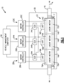
Figure 1 is a schematic view of an actuator system. -
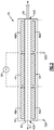
Figure 2 is a schematic view of an example LVDT that may be used in the actuator system ofFigure 1 . -
Figure 3 is a schematic view of an example circuit card assembly (CCA) that may be used in the actuator system ofFigure 1 . -
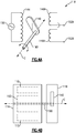
Figure 4A is a first schematic view of an example rotational variable differential transformer (RVDT) configured to measure rotational displacement of a stepper motor. -
Figure 4B is a second schematic view of the example RVDT ofFigure 4A . -
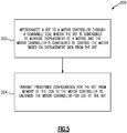
Figure 5 summarizes an example method of configuring a motor controller in a flowchart diagram. -
Figure 1 is a schematic view of anexample actuator system 10 that includes alinear actuator 12 and a plurality oflinear motors 14A-C. Each of thelinear motors 14 includes at least one respective stator 15. - The
linear actuator 12 includes aforcer rod 16 that extends along a central longitudinal axis A. A plurality ofmagnets 17 surround theforcer rod 16 along a length of theforcer rod 16. - The
forcer rod 16 is movable along the central longitudinal axis A by applying a voltage to one or more of the stators 15. If a voltage is provided in each of the threestators 15A-C, they can cooperatively move the rod along the longitudinal axis A. If one of thelinear motors 14A-C is unavailable, the remaining ones of thelinear motors 14A-C can increase their output to compensate for the unavailable motor. The rotor of eachlinear motor 14A-C corresponds to a portion of theforcer rod 16 and the portion's surroundingmagnets 17. - A plurality of
LVDTs 18A-C are redundantly configured to measure a linear displacement of theforcer rod 16. EachLVDT 18 is associated with a respective one of thelinear motors 14A. In the example ofFigure 1 ,linear motor 14A is associated with LVDT 18A,linear motor 14B is associated with LVDT 18B, andlinear motor 14C is associated with LVDT 18C. - The
system 10 includes a plurality ofmotor controllers 20A-C that are each operable to control a respective, associated one of thelinear motors 14A-C. Each motor controller 20 receives displacement data about its associatedlinear motor 14 from the LVDT 18 associated with thatmotor 14, and is configured to control its associatedlinear motor 14 based on the displacement data. - A
vehicle management computer 30 is in communication with the plurality ofmotor controllers 20A and is operable to provide actuator commands that themotor controllers 20A-C carry out. - Each motor controller 20 has a
respective control lane 32 that is utilized for sending signals to its associatedlinear motor 14 and obtaining displacement data from its associatedLVDT 18. - The
actuator system 10 includes a plurality of circuit card assemblies (CCAs) 34A-C. Each CCA 34 includes a printed circuit board on which a circuit, including circuit components, is provided. Each CCA 34 is connected to the CCA 34 of anothercontrol lane 32 to provide for communication between thecontrol lanes 32. - Each CCA 34 includes memory storing predefined configuration data of its associated
LVDT 18, and is configured to provide that configuration data to the motor controller 20 associated with thatLVDT 18 to calibrate the motor controller 20 for use of theLVDT 18. In one example, each CCA 34 is configured to provide the configuration data to the motor controller 20 at startup of theactuator system 10 in a calibration process of the motor controller 20. This enables the motor controller 20 to self-configure itself based on the configuration data, and avoids the manual configuration process of the prior art. - A
housing 36 is provided that at least partially encloses thelinear motors 14,LVDTs 18, andCCAs 34. The plurality of motor controllers 20 are outside thehousing 36 and are spaced apart from thehousing 36. - In one example, the
housing 36 and its contents are provided from a vendor as a self-contained unit, which provides for convenient automatic configuration of eachmotor controller 20A-C when connected to theCCAs 34 andlinear motors 14. - Referring now to
Figure 2 , an example LVDT 18 is shown. The LVDT 18 includes acore 40 that extends betweenopposing ends 42A-B of theLVDT 18 and is moveable along a central longitudinal axis B of theLVDT 18. The central longitudinal axis B is parallel to the central longitudinal axis A ofFigure 1 . A plurality ofwindings core 40. The winding 44 is a primary winding, and is situated axially betweensecondary windings shield 48 surrounds thewindings forcer rod 16 on theLVDT 18. The twosecondary windings 46A-B are series-opposed, which means they are wound in series but in opposite directions. - A
power source 50 is connected to opposing ends of the winding 44. When thepower source 50 energizes theprimary winding 44, a magnetic field is provided that induces a voltage in thesecondary windings secondary windings 46A-B are series-opposed, their induced signals are 180° out of phase with each other. - An
extension rod 54 extends from one end of thecore 40 and is mechanically coupled to theforcer rod 16, such that axial movement of theforcer rod 16 along central longitudinal axis A causes linear movement of theLVDT core 40 along central longitudinal axis B in the same direction and by a same distance. - As the
LVDT core 40 moves linearly along central longitudinal axis B, a magnetic field within theLVDT 18 changes, which changes the phase and amplitude of the output signal of theLVDT 18. The motor controller 20 associated with theLVDT 18 is connected to theoutput terminals 52A-B and is configured to measure the output signal and determine a linear position of the core 40 based on the output signal. - The configuration data stored in each
CCA 34 includesLVDT 18 output values for predefined linear positions of the core 40 (e.g., fully extended, fully retracted, and an intermediate position). These baseline values calibrate the motor controller 20 for the specific values of its associatedLVDT 18, enabling the motor controller 20 to accurately determine the position of its associatedLVDT core 40, and correspondingly the position of theforcer rod 16. In one example, the configuration data includes LVDT "rigging data" corresponding to a plurality of predefined positions of theLVDT core 40, and LVDT alignment constants corresponding to electrical output values of theLVDT 18 at those predefined positions. Such configuration information is also known as "trim data" or "personality data" for theLVDT 18. -
Figure 3 is a schematic view of anexample CCA 34 that may be used in theactuator system 10 ofFigure 1 . TheCCA 34 includes a plurality ofports 60A-C. Port 60A connects to the motor controller 20 of the CCA'scontrol lane 32,port 60B connects to theLVDT 18 of the CCA'scontrol lane 32, andport 60C connects to theCCA 34 of anothercontrol lane 32. In one example, the ports 60 are serial ports. - The
CCA 34 includesmemory 62 that stores predefined configuration data of its associatedLVDT 18. The configuration data could include any of the following, for example: the displacement range of its associatedlinear motor 14, the gains to be used by the motor controller 20 in a control algorithm for the associated linear motor 14 ("control law gains"), predefined linear positions for the associatedLVDT 18, andLVDT 18 output values corresponding to the predefined linear positions. In one example, thememory 62 also stores a fault history of its associatedlinear motor 14 based on data received from its associated motor controller 20. The fault history could include specific fault codes along with a date and time of fault occurrences. In one example, thememory 62 also stores data indicative of an amount of time that the associatedlinear motor 14 has been in service. In one example, thememory 62 comprises an electronically erasable programmable read-only memory (EEPROM) chip. - The motor controller 20 includes a plurality of signaling
lines 64A-I that connect to theport 60A. Although each signaling line 64 is depicted as a single line inFigure 3 , it is understood that each of the signaling lines 64 could include multiple lines (e.g., for multi-bit communications). - Signaling
line 64A is configured to communicate with and/orpower LVDT 18 viafeedthrough line 66A. - Signaling
line 64B is configured to provide a data output, chip select, and clock signal from the motor controller 20 to thememory 62. - Signaling
line 64C is configured to provide data from thememory 62 to the motor controller 20. - Signaling
line 64D is configured to provide a power and ground signal from the motor controller 20 to aregulator circuit 68 theCCA 34. Theregulator circuit 68 regulates a voltage used to power thememory 62. A resistor R1 is connected to signalingline 64E, which enables the motor controller 20 to monitor the voltage delivered to thememory 62. - Signaling
line 64F, which may include eight lines for eight bit communications, connects to theport 60C of anotherCCA 34 via feed throughline 66B and provides a cross-lane data link (CLDL). - Signaling
line 64G bypasses theCCA 34 and connects to a resistive thermal device "RTD" (not shown) for monitoring a temperature of thelinear motor 14 associated with the motor controller 20. In one example, signalingline 64G includes at least two lines to determine RTD data. - Signaling line 64H provides a filter return to the motor controller 20 from a resistor-
capacitor filter 70. - Signaling
line 641 provides an output for the motor controller 20 to control thelinear motor 14. In one example, signalingline 641 includes three lines, one for each winding of thelinear motor 14. Signalingline 641 also connects to theRC circuit 70 for EMI filtering. - The
RC filter 70 provides for electromagnetic interference (EMI) reduction of the power signal delivered to the various phases of thelinear motor 14 over signalingline 641. TheRC filter 70 includes at least one resistor R2 and at least one capacitor C1. In one example, theRC filter 70 includes at least one resistor R2 and at least one capacitor C1 for each of a plurality of phase of the power signal delivered over a plurality of the signaling lines 641 (e.g., three phases and three lines). Additional resistors and/or capacitors can be added to the RC filter(s) 70 as desired to adjust the filtering. In one example, additional resistors and capacitors are stored in astorage area 72 of theCCA 34. - The
CCA 34 provides a convenient way to interconnect a givenlinear motor 14 to its associated motor controller 20, and to provide for communication betweencontrol lanes 32. TheCCA 34 also provides for convenient self-configuration of a motor controller 20, which reduces the opportunity for the LVDT configuration data to be misconfigured by a technician, such as during initial deployment or field replacement of aLVDT 18. If aLVDT 18 needs to be replaced, anew CCA 34 that is preloaded with that configuration data can be quickly swapped out, providing for minimal downtime of theactuator system 10. Alternatively, the previous configuration data stored in thememory 62 for the replacedLVDT 18 can be overwritten with configuration data for thenew LVDT 18. Because it is removable, theCCA 34 can be conveniently swapped out or removed for updating, for example. Still further, theCCA 34 provides a convenient way to retain data about a fault history of a given motor. - Although LVDTs are described above, the
actuator system 10 discussed above could also be used for other types of variable differential transformers, such as rotary variable differential transformers (RVDTs), and thememory 62 of theCCA 34 could include configuration data for the RVDT. - In this disclosure, like reference numerals designate like elements where appropriate and reference numerals with the addition of one-hundred or multiples thereof designate modified elements that are understood to incorporate the same features and benefits of the corresponding elements.
-
Figure 4A is a first schematic view of anexample RVDT 118 that is configured to measure rotational displacement. TheRVDT 118 includes amagnetic core 140 connected to ashaft 190 that is generally perpendicular to thecore 140. Theshaft 190 andcore 140 are configured to corotate about a longitudinal axisC. The RVDT 118 includes a primary winding 144 and twosecondary windings 146A-B.A power source 150 is connected to opposing ends of the winding 144. When thepower source 150 energizes the primary winding 144, a magnetic field is provided that induces a voltage in thesecondary windings RVDT core 140 rotates about longitudinal axis C, a magnetic field within theRVDT 118 changes and alters an output signal of the twosecondary windings 146A-B, which is measurable usingterminals 152A-B to determine a rotational displacement of theRVDT core 140. -
Figure 4B is a schematic view of theRVDT 118 adjacent to anexample stepper motor 114. Thestepper motor 114 includes at least onestator 115 and at least one rotor (shown schematically as 192) coupled to theshaft 190. The at least onestator 115 is configured to provide a magnetic field that rotates the at least onerotor 192, which causes rotation of theshaft 190. The at least onerotor 192 andcore 140 are both coupled to theshaft 190 and corotate about the longitudinal axis C. Through this corotation, theRVDT 118 is configured to measure rotational displacement of thestepper motor 114. In one example, thestepper motor 114 has a predefined range of rotation (e.g., ± 60°). Similar to what is illustrated inFigure 1 , a plurality ofRVDTs 118 could be used to measure displacement of a plurality ofstepper motors 114 that cooperatively rotate a common shaft. -
Figure 5 summarizes an example method of configuring a motor controller in a flowchart diagram 200. A VDT (e.g.,LVDT 18 or RVDT 118) is interconnected to a motor controller 20 through aremovable CCA 34 at 202. The VDT is configured to measure displacement of a motor (e.g.,linear motor 14 or stepper motor 114), and the motor controller 20 is configured to control the motor based on displacement data from the VDT. Predefined configuration data for the VDT is transmitted frommemory 62 of theCCA 34 to the motor controller 20 to calibrate the motor controller 20 for use of the VDT at 204. - The motor controller 20 provides a power signal to the motor based on the predefined configuration data and based on displacement data from the VDT. A
filter circuit 70 of theCCA 34 is utilized to reduce electromagnetic interference (EMI) in the power signal. - Although example embodiments have been disclosed, a worker of ordinary skill in this art would recognize that the description is illustrative rather than limiting. Certain modifications would come within the scope of the invention as defined by the claims. For that reason, the following claims should be studied to determine the scope and content of legal protection.
Claims (15)
Applications Claiming Priority (1)
| Application Number | Priority Date | Filing Date | Title |
|---|---|---|---|
| US15/946,980 US11002569B2 (en) | 2018-04-06 | 2018-04-06 | Actuator control system utilizing circuit card assembly |
Publications (2)
| Publication Number | Publication Date |
|---|---|
| EP3550719A1 true EP3550719A1 (en) | 2019-10-09 |
| EP3550719B1 EP3550719B1 (en) | 2021-11-03 |
Family
ID=66092251
Family Applications (1)
| Application Number | Title | Priority Date | Filing Date |
|---|---|---|---|
| EP19167411.8A Active EP3550719B1 (en) | 2018-04-06 | 2019-04-04 | Actuator control system utilizing circuit card assembly |
Country Status (2)
| Country | Link |
|---|---|
| US (1) | US11002569B2 (en) |
| EP (1) | EP3550719B1 (en) |
Citations (4)
| Publication number | Priority date | Publication date | Assignee | Title |
|---|---|---|---|---|
| EP0830726A1 (en) * | 1995-06-07 | 1998-03-25 | Mts Systems Corporation | Electromagnetic actuator |
| EP3029819A1 (en) * | 2014-12-01 | 2016-06-08 | Hamilton Sundstrand Corporation | Electromechanical linear actuator |
| US20160329798A1 (en) * | 2015-05-07 | 2016-11-10 | Sikorsky Aircraft Corporation | Linear electromechanical actuators |
| US20170241810A1 (en) * | 2014-10-24 | 2017-08-24 | Moog Inc. | Position sensor assembly |
Family Cites Families (11)
| Publication number | Priority date | Publication date | Assignee | Title |
|---|---|---|---|---|
| US5493497A (en) | 1992-06-03 | 1996-02-20 | The Boeing Company | Multiaxis redundant fly-by-wire primary flight control system |
| WO2006130084A1 (en) * | 2005-05-31 | 2006-12-07 | Powerwave Technologies Sweden Ab | Beam adjusting device |
| US20100242492A1 (en) * | 2009-03-30 | 2010-09-30 | Honeywell International Inc. | Distributed engine control systems and gas turbine engines |
| FR2949921B1 (en) * | 2009-09-08 | 2013-08-23 | Thales Sa | SECURE SURVEILLANCE AND CONTROL DEVICE FOR AN AIRCRAFT STEERING ACTUATOR |
| US9242576B1 (en) * | 2014-07-25 | 2016-01-26 | GM Global Technology Operations LLC | Method and apparatus for controlling an electric machine |
| JP2018501758A (en) * | 2014-12-09 | 2018-01-18 | ジョンソン コントロールズ テクノロジー カンパニーJohnson Controls Technology Company | Electromagnetic compatibility filter |
| JP6140229B2 (en) * | 2015-08-28 | 2017-05-31 | ファナック株式会社 | Machine learning device and method for learning predicted life of electric motor, life prediction device and motor system provided with machine learning device |
| US9862365B2 (en) | 2016-01-22 | 2018-01-09 | Goodrich Corporation | Systems and methods for reducing disturbances caused by using gain scheduling in electronic brake actuator controls |
| US10111376B2 (en) * | 2016-03-30 | 2018-10-30 | Steering Solutions Ip Holding Corporation | Seed depth auto-learn system associated with a seed depth device for an agricultural planter |
| US10328872B2 (en) | 2016-06-29 | 2019-06-25 | Hamilton Sundstrand Corporation | Methodology for simplification of aircraft harnessing in multi-redundant control systems |
| US11424027B2 (en) * | 2017-12-28 | 2022-08-23 | Cilag Gmbh International | Method for operating surgical instrument systems |
-
2018
- 2018-04-06 US US15/946,980 patent/US11002569B2/en active Active
-
2019
- 2019-04-04 EP EP19167411.8A patent/EP3550719B1/en active Active
Patent Citations (4)
| Publication number | Priority date | Publication date | Assignee | Title |
|---|---|---|---|---|
| EP0830726A1 (en) * | 1995-06-07 | 1998-03-25 | Mts Systems Corporation | Electromagnetic actuator |
| US20170241810A1 (en) * | 2014-10-24 | 2017-08-24 | Moog Inc. | Position sensor assembly |
| EP3029819A1 (en) * | 2014-12-01 | 2016-06-08 | Hamilton Sundstrand Corporation | Electromechanical linear actuator |
| US20160329798A1 (en) * | 2015-05-07 | 2016-11-10 | Sikorsky Aircraft Corporation | Linear electromechanical actuators |
Also Published As
| Publication number | Publication date |
|---|---|
| US11002569B2 (en) | 2021-05-11 |
| US20190310110A1 (en) | 2019-10-10 |
| EP3550719B1 (en) | 2021-11-03 |
Similar Documents
| Publication | Publication Date | Title |
|---|---|---|
| DE10037968B4 (en) | Electric drive with engine identification and engine identification procedure | |
| DE69601866T2 (en) | Electronic control device for internal combustion engines of agricultural tractors with a plug-in memory card, which contains typical engine data determined during the test in the factory | |
| EP0896265B1 (en) | Driving device | |
| US20140225599A1 (en) | Transformer based sensor arrangement | |
| DE112006000835B4 (en) | Signal conditioning system for an inductive position sensor | |
| EP4211518B1 (en) | Intrinsically safe automation field device | |
| EP3550719B1 (en) | Actuator control system utilizing circuit card assembly | |
| EP2781774B1 (en) | Method for correcting variations of parameters of components and/or of assembly of active magnetic bearing and active magnetic bearing for bearing rotating working means | |
| EP3571749A1 (en) | Winding temperature monitoring | |
| DE19831931A1 (en) | Drive device | |
| DE102007033881A1 (en) | Rotor-stator unit with non-contact state detection, corresponding evaluation device and computer program for a software programmable evaluation device | |
| DE102012103245A1 (en) | Method for starting of powertrain with drive controller and machine in vehicle, involves assigning equivalent circuit data of machine to course of starting up of powertrain from storage unit by sorting and memorizing circuit data | |
| WO2010075926A1 (en) | Device and method for operating a drive | |
| EP3891030B1 (en) | Electromagnetic device for a braking system for a vehicle, method for operating an electromagnetic device for a braking system for a vehicle, and braking system for a vehicle | |
| EP1721223A1 (en) | Automation system and method for identifying and correcting connection errors | |
| EP3556110B1 (en) | Characterization using multiplexed resistance reading | |
| WO2023066590A1 (en) | Intrinsically safe automation field device | |
| DE102020216148A1 (en) | Method for calibrating a device for determining the temperature of a rotor of an electrical machine | |
| EP2275888A2 (en) | Rotor position sensor with a compensation unit for compensating for errors for a speed-controlled servomotor | |
| DE10118072B4 (en) | Procedure for securing the validity and management of engine-specific data | |
| EP4449138B1 (en) | Method and device for checking the plausibility of a termperature in a component of an electrical machine in a technical system | |
| EP4497043A1 (en) | Intrinsically safe automation field device | |
| EP2184591B1 (en) | Sensor comprising memory-equipped modules | |
| EP4097840B1 (en) | Device and method for operating a drive system | |
| CN106067745A (en) | For running method and the driving means of motor |
Legal Events
| Date | Code | Title | Description |
|---|---|---|---|
| PUAI | Public reference made under article 153(3) epc to a published international application that has entered the european phase |
Free format text: ORIGINAL CODE: 0009012 |
|
| STAA | Information on the status of an ep patent application or granted ep patent |
Free format text: STATUS: THE APPLICATION HAS BEEN PUBLISHED |
|
| AK | Designated contracting states |
Kind code of ref document: A1 Designated state(s): AL AT BE BG CH CY CZ DE DK EE ES FI FR GB GR HR HU IE IS IT LI LT LU LV MC MK MT NL NO PL PT RO RS SE SI SK SM TR |
|
| AX | Request for extension of the european patent |
Extension state: BA ME |
|
| STAA | Information on the status of an ep patent application or granted ep patent |
Free format text: STATUS: REQUEST FOR EXAMINATION WAS MADE |
|
| 17P | Request for examination filed |
Effective date: 20191216 |
|
| RBV | Designated contracting states (corrected) |
Designated state(s): AL AT BE BG CH CY CZ DE DK EE ES FI FR GB GR HR HU IE IS IT LI LT LU LV MC MK MT NL NO PL PT RO RS SE SI SK SM TR |
|
| STAA | Information on the status of an ep patent application or granted ep patent |
Free format text: STATUS: EXAMINATION IS IN PROGRESS |
|
| 17Q | First examination report despatched |
Effective date: 20201217 |
|
| GRAP | Despatch of communication of intention to grant a patent |
Free format text: ORIGINAL CODE: EPIDOSNIGR1 |
|
| STAA | Information on the status of an ep patent application or granted ep patent |
Free format text: STATUS: GRANT OF PATENT IS INTENDED |
|
| INTG | Intention to grant announced |
Effective date: 20210520 |
|
| RIN1 | Information on inventor provided before grant (corrected) |
Inventor name: ELDRIDGE, JEFFREY A. Inventor name: AVRITCH, STEVEN A. |
|
| GRAS | Grant fee paid |
Free format text: ORIGINAL CODE: EPIDOSNIGR3 |
|
| GRAA | (expected) grant |
Free format text: ORIGINAL CODE: 0009210 |
|
| STAA | Information on the status of an ep patent application or granted ep patent |
Free format text: STATUS: THE PATENT HAS BEEN GRANTED |
|
| AK | Designated contracting states |
Kind code of ref document: B1 Designated state(s): AL AT BE BG CH CY CZ DE DK EE ES FI FR GB GR HR HU IE IS IT LI LT LU LV MC MK MT NL NO PL PT RO RS SE SI SK SM TR |
|
| REG | Reference to a national code |
Ref country code: GB Ref legal event code: FG4D |
|
| REG | Reference to a national code |
Ref country code: AT Ref legal event code: REF Ref document number: 1444897 Country of ref document: AT Kind code of ref document: T Effective date: 20211115 Ref country code: CH Ref legal event code: EP |
|
| REG | Reference to a national code |
Ref country code: IE Ref legal event code: FG4D |
|
| REG | Reference to a national code |
Ref country code: DE Ref legal event code: R096 Ref document number: 602019008821 Country of ref document: DE |
|
| REG | Reference to a national code |
Ref country code: LT Ref legal event code: MG9D |
|
| REG | Reference to a national code |
Ref country code: NL Ref legal event code: MP Effective date: 20211103 |
|
| REG | Reference to a national code |
Ref country code: AT Ref legal event code: MK05 Ref document number: 1444897 Country of ref document: AT Kind code of ref document: T Effective date: 20211103 |
|
| PG25 | Lapsed in a contracting state [announced via postgrant information from national office to epo] |
Ref country code: RS Free format text: LAPSE BECAUSE OF FAILURE TO SUBMIT A TRANSLATION OF THE DESCRIPTION OR TO PAY THE FEE WITHIN THE PRESCRIBED TIME-LIMIT Effective date: 20211103 Ref country code: LT Free format text: LAPSE BECAUSE OF FAILURE TO SUBMIT A TRANSLATION OF THE DESCRIPTION OR TO PAY THE FEE WITHIN THE PRESCRIBED TIME-LIMIT Effective date: 20211103 Ref country code: FI Free format text: LAPSE BECAUSE OF FAILURE TO SUBMIT A TRANSLATION OF THE DESCRIPTION OR TO PAY THE FEE WITHIN THE PRESCRIBED TIME-LIMIT Effective date: 20211103 Ref country code: BG Free format text: LAPSE BECAUSE OF FAILURE TO SUBMIT A TRANSLATION OF THE DESCRIPTION OR TO PAY THE FEE WITHIN THE PRESCRIBED TIME-LIMIT Effective date: 20220203 Ref country code: AT Free format text: LAPSE BECAUSE OF FAILURE TO SUBMIT A TRANSLATION OF THE DESCRIPTION OR TO PAY THE FEE WITHIN THE PRESCRIBED TIME-LIMIT Effective date: 20211103 |
|
| PG25 | Lapsed in a contracting state [announced via postgrant information from national office to epo] |
Ref country code: IS Free format text: LAPSE BECAUSE OF FAILURE TO SUBMIT A TRANSLATION OF THE DESCRIPTION OR TO PAY THE FEE WITHIN THE PRESCRIBED TIME-LIMIT Effective date: 20220303 Ref country code: SE Free format text: LAPSE BECAUSE OF FAILURE TO SUBMIT A TRANSLATION OF THE DESCRIPTION OR TO PAY THE FEE WITHIN THE PRESCRIBED TIME-LIMIT Effective date: 20211103 Ref country code: PT Free format text: LAPSE BECAUSE OF FAILURE TO SUBMIT A TRANSLATION OF THE DESCRIPTION OR TO PAY THE FEE WITHIN THE PRESCRIBED TIME-LIMIT Effective date: 20220303 Ref country code: PL Free format text: LAPSE BECAUSE OF FAILURE TO SUBMIT A TRANSLATION OF THE DESCRIPTION OR TO PAY THE FEE WITHIN THE PRESCRIBED TIME-LIMIT Effective date: 20211103 Ref country code: NO Free format text: LAPSE BECAUSE OF FAILURE TO SUBMIT A TRANSLATION OF THE DESCRIPTION OR TO PAY THE FEE WITHIN THE PRESCRIBED TIME-LIMIT Effective date: 20220203 Ref country code: NL Free format text: LAPSE BECAUSE OF FAILURE TO SUBMIT A TRANSLATION OF THE DESCRIPTION OR TO PAY THE FEE WITHIN THE PRESCRIBED TIME-LIMIT Effective date: 20211103 Ref country code: LV Free format text: LAPSE BECAUSE OF FAILURE TO SUBMIT A TRANSLATION OF THE DESCRIPTION OR TO PAY THE FEE WITHIN THE PRESCRIBED TIME-LIMIT Effective date: 20211103 Ref country code: HR Free format text: LAPSE BECAUSE OF FAILURE TO SUBMIT A TRANSLATION OF THE DESCRIPTION OR TO PAY THE FEE WITHIN THE PRESCRIBED TIME-LIMIT Effective date: 20211103 Ref country code: GR Free format text: LAPSE BECAUSE OF FAILURE TO SUBMIT A TRANSLATION OF THE DESCRIPTION OR TO PAY THE FEE WITHIN THE PRESCRIBED TIME-LIMIT Effective date: 20220204 Ref country code: ES Free format text: LAPSE BECAUSE OF FAILURE TO SUBMIT A TRANSLATION OF THE DESCRIPTION OR TO PAY THE FEE WITHIN THE PRESCRIBED TIME-LIMIT Effective date: 20211103 |
|
| PG25 | Lapsed in a contracting state [announced via postgrant information from national office to epo] |
Ref country code: SM Free format text: LAPSE BECAUSE OF FAILURE TO SUBMIT A TRANSLATION OF THE DESCRIPTION OR TO PAY THE FEE WITHIN THE PRESCRIBED TIME-LIMIT Effective date: 20211103 Ref country code: SK Free format text: LAPSE BECAUSE OF FAILURE TO SUBMIT A TRANSLATION OF THE DESCRIPTION OR TO PAY THE FEE WITHIN THE PRESCRIBED TIME-LIMIT Effective date: 20211103 Ref country code: RO Free format text: LAPSE BECAUSE OF FAILURE TO SUBMIT A TRANSLATION OF THE DESCRIPTION OR TO PAY THE FEE WITHIN THE PRESCRIBED TIME-LIMIT Effective date: 20211103 Ref country code: EE Free format text: LAPSE BECAUSE OF FAILURE TO SUBMIT A TRANSLATION OF THE DESCRIPTION OR TO PAY THE FEE WITHIN THE PRESCRIBED TIME-LIMIT Effective date: 20211103 Ref country code: DK Free format text: LAPSE BECAUSE OF FAILURE TO SUBMIT A TRANSLATION OF THE DESCRIPTION OR TO PAY THE FEE WITHIN THE PRESCRIBED TIME-LIMIT Effective date: 20211103 Ref country code: CZ Free format text: LAPSE BECAUSE OF FAILURE TO SUBMIT A TRANSLATION OF THE DESCRIPTION OR TO PAY THE FEE WITHIN THE PRESCRIBED TIME-LIMIT Effective date: 20211103 |
|
| REG | Reference to a national code |
Ref country code: DE Ref legal event code: R097 Ref document number: 602019008821 Country of ref document: DE |
|
| PLBE | No opposition filed within time limit |
Free format text: ORIGINAL CODE: 0009261 |
|
| STAA | Information on the status of an ep patent application or granted ep patent |
Free format text: STATUS: NO OPPOSITION FILED WITHIN TIME LIMIT |
|
| 26N | No opposition filed |
Effective date: 20220804 |
|
| PG25 | Lapsed in a contracting state [announced via postgrant information from national office to epo] |
Ref country code: AL Free format text: LAPSE BECAUSE OF FAILURE TO SUBMIT A TRANSLATION OF THE DESCRIPTION OR TO PAY THE FEE WITHIN THE PRESCRIBED TIME-LIMIT Effective date: 20211103 |
|
| PG25 | Lapsed in a contracting state [announced via postgrant information from national office to epo] |
Ref country code: SI Free format text: LAPSE BECAUSE OF FAILURE TO SUBMIT A TRANSLATION OF THE DESCRIPTION OR TO PAY THE FEE WITHIN THE PRESCRIBED TIME-LIMIT Effective date: 20211103 |
|
| REG | Reference to a national code |
Ref country code: CH Ref legal event code: PL |
|
| REG | Reference to a national code |
Ref country code: BE Ref legal event code: MM Effective date: 20220430 |
|
| PG25 | Lapsed in a contracting state [announced via postgrant information from national office to epo] |
Ref country code: MC Free format text: LAPSE BECAUSE OF FAILURE TO SUBMIT A TRANSLATION OF THE DESCRIPTION OR TO PAY THE FEE WITHIN THE PRESCRIBED TIME-LIMIT Effective date: 20211103 Ref country code: LU Free format text: LAPSE BECAUSE OF NON-PAYMENT OF DUE FEES Effective date: 20220404 Ref country code: LI Free format text: LAPSE BECAUSE OF NON-PAYMENT OF DUE FEES Effective date: 20220430 Ref country code: CH Free format text: LAPSE BECAUSE OF NON-PAYMENT OF DUE FEES Effective date: 20220430 |
|
| PG25 | Lapsed in a contracting state [announced via postgrant information from national office to epo] |
Ref country code: BE Free format text: LAPSE BECAUSE OF NON-PAYMENT OF DUE FEES Effective date: 20220430 |
|
| PG25 | Lapsed in a contracting state [announced via postgrant information from national office to epo] |
Ref country code: IE Free format text: LAPSE BECAUSE OF NON-PAYMENT OF DUE FEES Effective date: 20220404 |
|
| PG25 | Lapsed in a contracting state [announced via postgrant information from national office to epo] |
Ref country code: IT Free format text: LAPSE BECAUSE OF FAILURE TO SUBMIT A TRANSLATION OF THE DESCRIPTION OR TO PAY THE FEE WITHIN THE PRESCRIBED TIME-LIMIT Effective date: 20211103 |
|
| P01 | Opt-out of the competence of the unified patent court (upc) registered |
Effective date: 20230522 |
|
| PG25 | Lapsed in a contracting state [announced via postgrant information from national office to epo] |
Ref country code: HU Free format text: LAPSE BECAUSE OF FAILURE TO SUBMIT A TRANSLATION OF THE DESCRIPTION OR TO PAY THE FEE WITHIN THE PRESCRIBED TIME-LIMIT; INVALID AB INITIO Effective date: 20190404 |
|
| PG25 | Lapsed in a contracting state [announced via postgrant information from national office to epo] |
Ref country code: MK Free format text: LAPSE BECAUSE OF FAILURE TO SUBMIT A TRANSLATION OF THE DESCRIPTION OR TO PAY THE FEE WITHIN THE PRESCRIBED TIME-LIMIT Effective date: 20211103 Ref country code: CY Free format text: LAPSE BECAUSE OF FAILURE TO SUBMIT A TRANSLATION OF THE DESCRIPTION OR TO PAY THE FEE WITHIN THE PRESCRIBED TIME-LIMIT Effective date: 20211103 |
|
| PG25 | Lapsed in a contracting state [announced via postgrant information from national office to epo] |
Ref country code: MT Free format text: LAPSE BECAUSE OF FAILURE TO SUBMIT A TRANSLATION OF THE DESCRIPTION OR TO PAY THE FEE WITHIN THE PRESCRIBED TIME-LIMIT Effective date: 20211103 |
|
| PGFP | Annual fee paid to national office [announced via postgrant information from national office to epo] |
Ref country code: DE Payment date: 20250319 Year of fee payment: 7 |
|
| PG25 | Lapsed in a contracting state [announced via postgrant information from national office to epo] |
Ref country code: TR Free format text: LAPSE BECAUSE OF FAILURE TO SUBMIT A TRANSLATION OF THE DESCRIPTION OR TO PAY THE FEE WITHIN THE PRESCRIBED TIME-LIMIT Effective date: 20211103 |
|
| PGFP | Annual fee paid to national office [announced via postgrant information from national office to epo] |
Ref country code: GB Payment date: 20260319 Year of fee payment: 8 |
|
| PGFP | Annual fee paid to national office [announced via postgrant information from national office to epo] |
Ref country code: FR Payment date: 20260320 Year of fee payment: 8 |