EP3550702A1 - Electrical winding topologies comprising heatpipes - Google Patents
Electrical winding topologies comprising heatpipes Download PDFInfo
- Publication number
- EP3550702A1 EP3550702A1 EP19166415.0A EP19166415A EP3550702A1 EP 3550702 A1 EP3550702 A1 EP 3550702A1 EP 19166415 A EP19166415 A EP 19166415A EP 3550702 A1 EP3550702 A1 EP 3550702A1
- Authority
- EP
- European Patent Office
- Prior art keywords
- windings
- core
- electrical winding
- heat
- electrical
- Prior art date
- Legal status (The legal status is an assumption and is not a legal conclusion. Google has not performed a legal analysis and makes no representation as to the accuracy of the status listed.)
- Withdrawn
Links
Images


Classifications
-
- H—ELECTRICITY
- H02—GENERATION; CONVERSION OR DISTRIBUTION OF ELECTRIC POWER
- H02K—DYNAMO-ELECTRIC MACHINES
- H02K3/00—Details of windings
- H02K3/04—Windings characterised by the conductor shape, form or construction, e.g. with bar conductors
- H02K3/12—Windings characterised by the conductor shape, form or construction, e.g. with bar conductors arranged in slots
-
- H—ELECTRICITY
- H02—GENERATION; CONVERSION OR DISTRIBUTION OF ELECTRIC POWER
- H02K—DYNAMO-ELECTRIC MACHINES
- H02K1/00—Details of the magnetic circuit
- H02K1/06—Details of the magnetic circuit characterised by the shape, form or construction
- H02K1/12—Stationary parts of the magnetic circuit
- H02K1/20—Stationary parts of the magnetic circuit with channels or ducts for flow of cooling medium
-
- F—MECHANICAL ENGINEERING; LIGHTING; HEATING; WEAPONS; BLASTING
- F28—HEAT EXCHANGE IN GENERAL
- F28D—HEAT-EXCHANGE APPARATUS, NOT PROVIDED FOR IN ANOTHER SUBCLASS, IN WHICH THE HEAT-EXCHANGE MEDIA DO NOT COME INTO DIRECT CONTACT
- F28D15/00—Heat-exchange apparatus with the intermediate heat-transfer medium in closed tubes passing into or through the conduit walls ; Heat-exchange apparatus employing intermediate heat-transfer medium or bodies
- F28D15/02—Heat-exchange apparatus with the intermediate heat-transfer medium in closed tubes passing into or through the conduit walls ; Heat-exchange apparatus employing intermediate heat-transfer medium or bodies in which the medium condenses and evaporates, e.g. heat pipes
- F28D15/04—Heat-exchange apparatus with the intermediate heat-transfer medium in closed tubes passing into or through the conduit walls ; Heat-exchange apparatus employing intermediate heat-transfer medium or bodies in which the medium condenses and evaporates, e.g. heat pipes with tubes having a capillary structure
- F28D15/043—Heat-exchange apparatus with the intermediate heat-transfer medium in closed tubes passing into or through the conduit walls ; Heat-exchange apparatus employing intermediate heat-transfer medium or bodies in which the medium condenses and evaporates, e.g. heat pipes with tubes having a capillary structure forming loops, e.g. capillary pumped loops
-
- H—ELECTRICITY
- H02—GENERATION; CONVERSION OR DISTRIBUTION OF ELECTRIC POWER
- H02K—DYNAMO-ELECTRIC MACHINES
- H02K3/00—Details of windings
- H02K3/04—Windings characterised by the conductor shape, form or construction, e.g. with bar conductors
- H02K3/24—Windings characterised by the conductor shape, form or construction, e.g. with bar conductors with channels or ducts for cooling medium between the conductors
-
- H—ELECTRICITY
- H02—GENERATION; CONVERSION OR DISTRIBUTION OF ELECTRIC POWER
- H02K—DYNAMO-ELECTRIC MACHINES
- H02K9/00—Arrangements for cooling or ventilating
-
- H—ELECTRICITY
- H02—GENERATION; CONVERSION OR DISTRIBUTION OF ELECTRIC POWER
- H02K—DYNAMO-ELECTRIC MACHINES
- H02K9/00—Arrangements for cooling or ventilating
- H02K9/22—Arrangements for cooling or ventilating by solid heat conducting material embedded in, or arranged in contact with, the stator or rotor, e.g. heat bridges
- H02K9/225—Heat pipes
-
- H—ELECTRICITY
- H02—GENERATION; CONVERSION OR DISTRIBUTION OF ELECTRIC POWER
- H02K—DYNAMO-ELECTRIC MACHINES
- H02K2209/00—Specific aspects not provided for in the other groups of this subclass relating to systems for cooling or ventilating
Definitions
- Embodiments of the present specification relate to electrical winding topologies, and more particularly, embodiments of the present specification relate to electrical topologies with enhanced thermal management and methods of making such topologies.
- conventional thermal management mechanisms typically include providing one or more thermal paths configured to allow a flow of heat away from temperature sensitive components of the electrical machines. For example, in the electrical machines that utilize electrical windings having several insulation layers, heat generated in the electrical windings traverses through various components, such as a coating of varnish, a turn insulation, a slot liner, a resin or epoxy, laminations, thermal interface at lamination-housing contact, and the like, in a thermal path before ultimately being rejected to a surrounding fluid.
- Heat transfer enhancement features such as fins or turbulators, are used in the electrical machines to facilitate rejection of heat from the components, transfer of heat from the components to the surrounding fluid, or both.
- these heat transfer enhancement features enhance the effective surface area available for convection and are capable of complementing other heat transfer mechanisms that may be employed by the electrical machines for the purpose of thermal management.
- an electrical winding topology having a core and a plurality of windings.
- the plurality of windings is operatively coupled to the core, where at least one of the plurality of windings includes an evaporator section and a condenser section. Further, at least a portion of one or more of the plurality of windings includes heat pipes.
- a thermal management system having an electrical winding topology.
- the electrical winding topology includes a core and a plurality of windings.
- the plurality of windings is operatively coupled to the core, where at least one of the plurality of windings includes an evaporator section and a condenser section. Further, at least a portion of one or more of the plurality of windings includes heat pipes.
- the thermal management system also includes an external cooling arrangement operatively coupled to one or more of the plurality of windings to transfer heat away from the one or more of the plurality of windings.
- an electrical winding topology having a core and a plurality of windings.
- the plurality of windings is operatively coupled to the core, where at least one of the plurality of windings includes an evaporator section and a condenser section.
- one or more of the plurality of windings include a composite structure having heat pipes and electrically conductive connecting elements.
- Embodiments of the present specification relate to cooling and thermal management, and more particularly to an electrical winding topology and a thermal management system employing the electrical winding topology of the present specification.
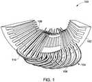
- FIG. 1 illustrates an electrical winding topology 100.
- the electrical winding topology 100 includes a core 102 and a plurality of windings generally referenced by reference numeral 104.
- the plurality of windings 104 is at least partly disposed in the core 102. Further, one or more of the windings 104 form a closed loop structure. Each closed loop structure is referred to as a single winding.
- a winding 104 may include a heat pipe 106.
- one or more of the plurality of windings 104 include heat pipes, such as heat pipes 106.
- one or more of the plurality of windings 104 include a composite structure having one or more heat pipes and one or more connecting elements.
- the connecting elements are electrically and thermally conductive structures that together with corresponding heat pipes form closed loop structures of the windings 104.
- the connecting elements may be solid or hollow structures that in conjunction with the heat pipes enable thermal and electrical functionality of the windings.
- Non-limiting examples of a connecting element include a hollow tube or a solid tube.
- a portion of the closed loop structure of a single winding may include a heat pipe and another portion of the closed loop structure may include a thermally and electrically conductive connecting element.
- the windings 104 may include a distributed winding arrangement or a concentrated winding arrangement.
- the plurality of windings 104 forms a continuous structure and outer walls of the heat pipes 106 and/or connecting elements provide a resistance-free electrical current path for the electrical current to flow.
- the windings 104 of the electrical winding topology 100 include electrical contacts that electrically connect the windings 104 to an electrical source or an electrical component.
- Each heat pipe 106 in general, includes an evaporator section 108 and a condenser section 110.
- the evaporator section 108 of the at least one of the plurality of windings 104 is disposed in the core 102.
- the condenser section 110 of the at least one of the plurality of windings is disposed outside the core 102.
- the evaporator section 108 of the windings 104 is disposed outside the core 102, and the condenser section 110 of the windings 104 is disposed in the core 102.
- the core 102 may be cooler than immediate surroundings of the core 102, where the evaporator section 108 is disposed. In some of these embodiments, the core 102 may be cooled via cooling ducts present in the core 102, or cooling ducts present near the windings 104, or a cooling jacket operatively coupled to the core 102.
- the core 102 is a stator core or a rotor core.
- the plurality of windings 104 includes a composite structure having heat pipes and electrically conductive connecting elements, the heat pipes may be disposed in the core 102 and the electrically conductive connecting element may be disposed outside the core 102, or vice versa.
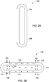
- FIGS. 2A-2B illustrate an example winding 202 of an electrical winding topology of an electrical motor (not illustrated in FIGS. 2A-2B ).
- the winding 202 includes a heat pipe 204 such that a closed loop structure 206 of the winding 202 is made of the heat pipe 206.
- FIG. 2A illustrates the closed loop structure 206 formed by the heat pipe 204
- FIG. 2B illustrates a cross-sectional view 210 of the heat pipe 204.
- the heat pipe 204 includes an outer wall 212 and a wick structure 218 disposed along an inner surface 214 of the outer wall 212.
- the heat pipe 204 is configured to house a coolant fluid 216 disposed within the wick structure 218.
- the wick structure 218 disposed along the inner surface 214 of the heat pipe 204 facilitates capillary action of the coolant fluid 216.
- the coolant fluid 216 may flow using centrifugal forces.
- centrifugal force may act as a primary force over the capillary action.
- the winding 202 is a closed loop structure that is sealed.
- the wick structure 218 is typically disposed between the coolant fluid 216 and the inner surface 214.
- copper or aluminum may be used to form the outer wall 212 of the heat pipe 204.
- water may be used as the coolant fluid 216 due to its suitable thermal characteristics.
- Arrows 220 represent a direction of heat input in the heat pipe 204
- arrows 222 represent heat output from the heat pipe 204.
- Portion of the heat pipe 204 where the heat enters is the evaporator section 208 and the opposite section is the condenser section 209.
- the coolant fluid 216 which is a volatile fluid, experiences a liquid to vapor phase transition using phase change heat transfer at operating conditions of the electrical winding topology.
- the coolant fluid 216 transitions from a liquid phase to a vapor phase at operating temperatures and pressures present in the electrical winding during the operation.
- the liquid phase coolant fluid experiences a centrifugal force against the outer wall 212 of a portion of the heat pipe 204.
- remaining portion of the heat pipe 204 may be occupied by essentially saturated vapor that is in equilibrium with the liquid phase of the coolant fluid.
- Heat is conducted through the outer wall 212 of the evaporator section 208 and is transferred to the liquid phase of the coolant fluid 216 present in the condenser section 209. Addition of heat in the evaporator section 208 causes evaporation or boiling of the volatile coolant fluid which generates a vapor which flows at a high speed to the condenser section 209 of the heat pipe 204.
- Flow of the vapors from the evaporator section 208 to the condenser section 209 is illustrated by arrows 224.
- the latent heat of the vapors of the coolant fluid 216 is transported by conduction through the wick structure 218 and a coolant fluid film, and subsequently via conduction through the outer walls 212 of the heat pipe 204.
- the condensed coolant fluid 216 present in the condenser section 209 then returns to the evaporator section 208, for example, by capillary action of the wick structure 218, along an inner surface 214 of the heat pipe 204.
- the condensed coolant fluid 216 returns to the evaporator section 208 of the heat pipe 204 to replace the coolant fluid 216 which is evaporated from the evaporator section 208, thus maintaining a constant liquid fraction and gas pressure at any steady state operating condition in the evaporator section 208 and the heat pipe 204, in general. Movement of the coolant fluid 216 from the condenser section 209 to the evaporator section 208 is represented by arrows 226. As the coolant fluid 216 travels toward the evaporator section 208, whether by capillary action or centrifugal forces, or both, the coolant fluid 216 may form a thin film, referred to as the coolant fluid film, along the inner surface 214 of the heat pipe 204.
- the condenser section 209 of the heat pipe 204 may be cooled by external cooling arrangements, such as a heat sink, or any other cooling medium.
- the outer walls 212 of the heat pipe 204 are configured to conduct electrical current during operation, thereby serving the dual purpose of conduction of electrical current and dissipation of heat.
- the winding 202 is formed from the heat pipe 204 such that the wick structure 218 forms a continuous structure within the winding 202. Bends of the closed loop structure 206 are defined such that the wick structure 218 can conform with the bends with minimal or no disintegration to prevent adverse effect on heat transport during operation of the electrical motor.
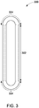
- FIG. 3 illustrates a winding 300 having a composite structure, where the composite structure includes portions containing heat pipes 302 and connecting portions having electrically and thermally conductive connecting elements 304.
- the heat pipes 302 form a linear section of the winding 300 and the connecting elements 304 form a curved section of the winding 300
- other configurations such as the heat pipes 302 forming the curved sections and/or connecting elements 304 forming the linear sections, or heat pipes 302 and connecting elements 304 forming portions of the curved and/or linear sections, are also envisioned within the purview of the present specification.
- the cross-sectional area of the connecting elements 304 may be similar to that of the heat pipes 302.
- the connecting elements 304 are electrically and thermally conductive structures. Further, the connecting elements 304 may be solid or hollow structures. Also, the connecting elements 304 may be made of copper, aluminum, or other similar materials that have a thermal as well as electrical conductivity similar to the material of outer walls of the heat pipe 302. Further, the heat pipes 302 and the connecting elements 304 may be joined using an electrically conductive solder that is able to maintain a solid state at operating temperatures of the winding 300.
- the electrically conductive solders may include solders with melting temperatures above 200 °C.
- Non-limiting examples of such electrically conductive solders include solders suitable for use in electrical motors and generators, such as Sn 95 Sb 5 , Pb 95 Sn 3 Ag 2 , Cd 82 Zn 16 Ag 2 , Cd 73 Zn 22 Ag 5 , and Cd 95 Ag 5 .
- one or more of the plurality of windings may include one or more local heat transfer enhancement features.
- the local heat transfer enhancement features are configured to enhance heat transfer efficiency of corresponding windings.
- the local heat transfer enhancement features may be present on inner surfaces of heat pipes, connecting elements, or on a rib or beam that runs along a certain external portion of a winding.
- the local heat transfer enhancement features enhance heat transfer within the winding.
- the local heat transfer enhancement features facilitate mixing and directing coolant fluid disposed in the winding.
- the local heat transfer enhancement features include turbulators. The turbulators are configured to cause disruption in flow of the coolant fluid present in the winding.
- the turbulators are disposed in the evaporator and/or condenser sections of the one or more windings.
- Non-limiting examples of the turbulators may include indentations, protrusions, ribs, channels, discontinuities, or combinations thereof.
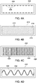
- FIGS. 4A-4B illustrate different examples of turbulators that may be employed in windings.
- FIG. 4A illustrates a portion of an example winding 402 of the present specification, where the winding 402 includes protrusions 404 disposed along an outer wall 406 of the winding 402.
- the winding 402 may include a heat pipe or a composite structure made of a heat pipe and a connecting element.
- FIG. 4B illustrates a portion of an example winding 410 of the present specification, where the winding 410 includes ribs 412 formed on an inner surface 414 of an outer wall 416 of the winding 410.
- the winding 410 may include a heat pipe, or a composite structure made of a heat pipe and a connecting element.
- FIG. 4C illustrates a portion of an example winding 420 of the present specification, where the winding 420 includes channels or struts 422 formed on an inner surface 424 of an outer wall 426 of the winding 420.
- the winding 420 may include a heat pipe or a composite structure made of a heat pipe and a connecting element.
- FIG. 4D illustrates a portion of an example winding 430 of the present specification, where the winding 430 includes a beam or pole 432 having a spiral blade 434 twisted around the pole 432.
- the winding 430 may include a heat pipe or a composite structure made of a heat pipe and a connecting element.
- FIG. 5 illustrates a thermal management system 500 having an electrical winding topology 502, such that one or more of a plurality of windings 504 are configured to be coupled to an external cooling arrangement, represented generally by block 506.
- the external cooling arrangement 506 is configured to provide at least localized cooling to the windings 504 with minimal to no disruption to the flow of electrical current during operation of the electrical winding topology 502.
- the external cooling arrangement 506 is external to the electrical winding topology 502. Further, the external cooling arrangement 506 may include a heat sink, a cooling jacket, or a cooling medium. In some embodiments, condenser sections of the windings 504 are operatively coupled to the external cooling arrangement 506.
- the heat sink may be operatively coupled to the condenser sections of the windings 504 to extract heat and provide cooling to the condenser sections of the windings 504.
- the heat sink may include one or more fins, wings, winglets, flaps, stubs, plates, rods, or combinations thereof.
- the windings 504 include the heat pipes
- heat released due to condensation is passed to outer walls of the heat pipes and subsequently to the external cooling arrangement 506.
- the heat of the coolant fluid present in the winding 504 is transferred from the coolant fluid to the outer walls of the heat pipes or connecting elements and subsequently to the external cooling arrangement 506.
- a cooling medium used as the external cooling arrangement 506 may include non-volatile or volatile coolant liquid.
- the coolant liquid may be sprayed on at least portions of one or more of the windings 504.
- the coolant liquid may be sprayed from stationary or rotary nozzles or by the flow of air or other gases.
- FIG. 6 illustrates a cross-sectional view of an electrical motor 600, in accordance with one exemplary embodiment of the present specification.
- the electrical motor 600 is a radial flux electrical machine.
- the electrical motor 600 includes a stator 602 and a rotor 604 disposed concentric to the stator 602 such that a thin air gap (not shown in FIG. 6 ) is established between the stator 602 and the rotor 604.
- the rotor 604 rotates relative to the stator 602.
- the electrical motor 600 may be a motor, where the rotor 604 moves relative to the stator 602 to convert electrical energy to mechanical energy.
- the electrical motor 600 may be an electrical generator, where the motion of the rotor 604 relative to the stator 602 converts mechanical energy to electrical energy.
- the rotor 604 is disposed within a stator 602.
- the stator 602 is disposed within a rotor 604.
- the stator 602 includes a stator core 606.
- the stator core 606 includes stator teeth 608 defining a plurality of stator slots 610. Each stator slot of the plurality of stator slots 610 is defined between a corresponding pair of adjacent stator teeth 608.
- the rotor 604 includes a rotor core 614.
- the rotor core 614 includes rotor teeth 616 defining a plurality of rotor slots 618. Each rotor slot 618 of the plurality of rotor slots 618 is defined between a corresponding pair of adjacent rotor teeth 616.
- the rotor 604 further includes a permanent magnet 620 disposed at least in one rotor slot 618.
- the rotor 604 is mounted on a shaft 622 and is configured to be driven by the rotor 604.
- the electrical motor 600 further includes a plurality of windings 612 operatively coupled to one of the stator core 606 or the rotor core 614.
- the windings 612 are shown to be disposed in the stator core 606.
- the windings 612 may be disposed in the rotor core 614.
- the windings 612 are disposed at least in one stator slot 610 of the stator core 606.
- at least one of the plurality of windings includes an evaporator section (not shown in FIG. 6 ) and a condenser section (not shown in FIG. 6 ).
- the evaporator section of the at least one of the plurality of windings 612 is disposed in the stator core 606, and the condenser section of the at least one of the windings 612 is disposed outside the stator core 606.
- at least a portion of one or more of the plurality of windings 612 includes heat pipes.
- one or more of the windings 612 form a closed loop.
- a phase-separator (not shown in FIG. 6 ) may be used to electrically insulate at least two of the windings 612 disposed in the same slot, such as the slot 610.
- the electrical motor 600 may be coupled to an external cooling arrangement (not shown in FIG. 6 ).
- an external cooling arrangement not shown in FIG. 6 .
- one or more windings 612 are operatively coupled to the external cooling arrangement.
- heat pipes in the windings of an electrical winding topology enhances both thermal and electrical performances of the electrical motor that employs such windings.
- the heat pipes may demonstrate 10X to 100X enhanced thermal conductivity relative to pure copper.
- the heat generated may be effectively pulled out of a stack of windings, independent of the stack length.
- using the windings to perform the dual role of electrical as well as thermal conduction minimizes design complications.
- use of heat pipes in the windings render these windings a self-regulating device, and obviates the need for a separate arrangement for thermal conduction.
- use of the heat pipes enables the windings to handle excess heat without changing coolant conditions for thermal management.
- a thermal management system comprising: an electrical winding topology, comprising: a core; a plurality of windings operatively coupled to the core, wherein at least one of the plurality of windings comprises an evaporator section and a condenser section, and wherein at least a portion of one or more of the plurality of windings comprises heat pipes; and an external cooling arrangement operatively coupled to one or more of the plurality of windings to transfer heat away from the one or more of the plurality of windings.
- thermo management system of the prior clause wherein the evaporator section of the at least one of the plurality of windings is disposed in the core, wherein the condenser section of the at least one of the plurality of stator windings is disposed outside the core, and wherein one or more of the plurality of windings comprise heat pipes.
- thermo management system of any prior clause wherein one or more of the plurality of windings are configured to be coupled to an electrical component.
- the external cooling arrangement comprises a heat sink
- the heat sink comprises one or more fins, wings, winglets, flaps, stubs, plates, rods, or combinations thereof.
- the core is a stator core or a rotor core.
- An electrical winding topology comprising a core; and a plurality of windings operatively coupled to the core, wherein at least one of the plurality of windings comprises an evaporator section and a condenser section, and wherein one or more of the plurality of windings comprise a composite structure comprising heat pipes and electrically conductive connecting elements.
Landscapes
- Engineering & Computer Science (AREA)
- Power Engineering (AREA)
- Life Sciences & Earth Sciences (AREA)
- Sustainable Development (AREA)
- Physics & Mathematics (AREA)
- Thermal Sciences (AREA)
- Mechanical Engineering (AREA)
- General Engineering & Computer Science (AREA)
- Motor Or Generator Cooling System (AREA)
Abstract
Description
- Embodiments of the present specification relate to electrical winding topologies, and more particularly, embodiments of the present specification relate to electrical topologies with enhanced thermal management and methods of making such topologies.
- Conventional electrical machines typically generate a significant amount of heat during routine operations. If not managed, the generated heat may accumulate, resulting in an undesirable rise in temperature in the electrical machine, and eventual damage or failure of components (such as insulation layers, wedges, magnets, or the like) of the electrical machines. For example, some estimates indicate that for every 10 °C (18 °F) rise in temperature, the life of the components may decrease by about 50%. In addition, the heat generated is waste energy, owing to inherent inefficiencies associated with converting input electrical energy to useful work. As such, managing the generated heat thus becomes imperative to ensuring the safe and reliable operation of the designed components. Moreover, such heat (thermal) management is a critical bottleneck in achieving improved power density.
- Further, conventional thermal management mechanisms typically include providing one or more thermal paths configured to allow a flow of heat away from temperature sensitive components of the electrical machines. For example, in the electrical machines that utilize electrical windings having several insulation layers, heat generated in the electrical windings traverses through various components, such as a coating of varnish, a turn insulation, a slot liner, a resin or epoxy, laminations, thermal interface at lamination-housing contact, and the like, in a thermal path before ultimately being rejected to a surrounding fluid.
- Heat transfer enhancement features, such as fins or turbulators, are used in the electrical machines to facilitate rejection of heat from the components, transfer of heat from the components to the surrounding fluid, or both. When properly designed, these heat transfer enhancement features enhance the effective surface area available for convection and are capable of complementing other heat transfer mechanisms that may be employed by the electrical machines for the purpose of thermal management.
- In one embodiment, an electrical winding topology having a core and a plurality of windings is provided. The plurality of windings is operatively coupled to the core, where at least one of the plurality of windings includes an evaporator section and a condenser section. Further, at least a portion of one or more of the plurality of windings includes heat pipes.
- In another embodiment, a thermal management system having an electrical winding topology is provided. The electrical winding topology includes a core and a plurality of windings. The plurality of windings is operatively coupled to the core, where at least one of the plurality of windings includes an evaporator section and a condenser section. Further, at least a portion of one or more of the plurality of windings includes heat pipes. The thermal management system also includes an external cooling arrangement operatively coupled to one or more of the plurality of windings to transfer heat away from the one or more of the plurality of windings.
- In yet another embodiment, an electrical winding topology having a core and a plurality of windings is provided. The plurality of windings is operatively coupled to the core, where at least one of the plurality of windings includes an evaporator section and a condenser section. Further, one or more of the plurality of windings include a composite structure having heat pipes and electrically conductive connecting elements.
- These and other features and aspects of embodiments of the invention will become better understood when the following detailed description is read with reference to the accompanying drawings in which like characters represent like parts throughout the drawings, wherein:
-
FIG. 1 is a diagrammatical illustration of an example electrical winding topology, in accordance with aspects of the present specification; -
FIGS. 2A-2B are diagrammatical representations of an example winding having a heat pipe, in accordance with aspects of the present specification; -
FIG. 3 is a diagrammatical representation of another example winding having a composite structure formed of heat pipes and connecting elements, in accordance with aspects of the present specification; -
FIG. 4A-4D are cross-sectional views of portions of windings having turbulators, in accordance with aspects of the present specification. -
FIG. 5 is a diagrammatical representation of an example thermal management system having an electrical winding topology, in accordance with aspects of the present specification; and -
FIG. 6 is a cross-sectional view of an electrical motor, in accordance with aspects of the present specification. - Embodiments of the present specification relate to cooling and thermal management, and more particularly to an electrical winding topology and a thermal management system employing the electrical winding topology of the present specification.
-
FIG. 1 illustrates anelectrical winding topology 100. Theelectrical winding topology 100 includes acore 102 and a plurality of windings generally referenced byreference numeral 104. The plurality ofwindings 104 is at least partly disposed in thecore 102. Further, one or more of thewindings 104 form a closed loop structure. Each closed loop structure is referred to as a single winding. - In certain embodiments, at least a portion of a winding 104 may include a
heat pipe 106. In some embodiments, as described with reference toFIGS. 2A-2B , one or more of the plurality ofwindings 104 include heat pipes, such asheat pipes 106. In same or different embodiments, as described with reference toFIG. 3 , one or more of the plurality ofwindings 104 include a composite structure having one or more heat pipes and one or more connecting elements. The connecting elements are electrically and thermally conductive structures that together with corresponding heat pipes form closed loop structures of thewindings 104. The connecting elements may be solid or hollow structures that in conjunction with the heat pipes enable thermal and electrical functionality of the windings. Non-limiting examples of a connecting element include a hollow tube or a solid tube. In some embodiments where one or more of the plurality of windings include the composite structure, a portion of the closed loop structure of a single winding may include a heat pipe and another portion of the closed loop structure may include a thermally and electrically conductive connecting element. - In certain embodiments, the
windings 104 may include a distributed winding arrangement or a concentrated winding arrangement. The plurality ofwindings 104 forms a continuous structure and outer walls of theheat pipes 106 and/or connecting elements provide a resistance-free electrical current path for the electrical current to flow. Thewindings 104 of theelectrical winding topology 100 include electrical contacts that electrically connect thewindings 104 to an electrical source or an electrical component. - Each
heat pipe 106, in general, includes anevaporator section 108 and acondenser section 110. In some embodiments where thewindings 104 includeheat pipes 106, theevaporator section 108 of the at least one of the plurality ofwindings 104 is disposed in thecore 102. Further, in these embodiments, thecondenser section 110 of the at least one of the plurality of windings is disposed outside thecore 102. Although not illustrated, in alternative embodiments, theevaporator section 108 of thewindings 104 is disposed outside thecore 102, and thecondenser section 110 of thewindings 104 is disposed in thecore 102. In these embodiments, thecore 102 may be cooler than immediate surroundings of thecore 102, where theevaporator section 108 is disposed. In some of these embodiments, thecore 102 may be cooled via cooling ducts present in thecore 102, or cooling ducts present near thewindings 104, or a cooling jacket operatively coupled to thecore 102. - In certain embodiments, the
core 102 is a stator core or a rotor core. In embodiments where the plurality ofwindings 104 includes a composite structure having heat pipes and electrically conductive connecting elements, the heat pipes may be disposed in thecore 102 and the electrically conductive connecting element may be disposed outside thecore 102, or vice versa. -
FIGS. 2A-2B illustrate an example winding 202 of an electrical winding topology of an electrical motor (not illustrated inFIGS. 2A-2B ). In the illustrated embodiments ofFIGS. 2A-2B , the winding 202 includes aheat pipe 204 such that aclosed loop structure 206 of the winding 202 is made of theheat pipe 206.FIG. 2A illustrates theclosed loop structure 206 formed by theheat pipe 204, andFIG. 2B illustrates across-sectional view 210 of theheat pipe 204. Theheat pipe 204 includes anouter wall 212 and awick structure 218 disposed along aninner surface 214 of theouter wall 212. Theheat pipe 204 is configured to house acoolant fluid 216 disposed within thewick structure 218. Thewick structure 218 disposed along theinner surface 214 of theheat pipe 204 facilitates capillary action of thecoolant fluid 216. In addition, in embodiments where there is rotation or revolution movement of the core 202 involved in the operation of the electrical motor, thecoolant fluid 216 may flow using centrifugal forces. In some embodiments, centrifugal force may act as a primary force over the capillary action. - The winding 202 is a closed loop structure that is sealed. The
wick structure 218 is typically disposed between thecoolant fluid 216 and theinner surface 214. In some embodiments, owing to their high thermal conductivity, copper or aluminum may be used to form theouter wall 212 of theheat pipe 204. In same or alternative embodiments, water may be used as thecoolant fluid 216 due to its suitable thermal characteristics. However, it may be noted that other choices are also common, depending on the amount of heat that is to be transported and operating conditions that are predicted to be present in the winding 202 during operation.Arrows 220 represent a direction of heat input in theheat pipe 204, andarrows 222 represent heat output from theheat pipe 204. Portion of theheat pipe 204 where the heat enters is theevaporator section 208 and the opposite section is thecondenser section 209. - During operation of the electrical winding topology, as the
heat pipe 204 absorbs surrounding heat, thecoolant fluid 216, which is a volatile fluid, experiences a liquid to vapor phase transition using phase change heat transfer at operating conditions of the electrical winding topology. By way of example, thecoolant fluid 216 transitions from a liquid phase to a vapor phase at operating temperatures and pressures present in the electrical winding during the operation. In certain embodiments, during rotation of the rotor of the electrical motor, when thecoolant fluid 216 is present in a liquid phase, the liquid phase coolant fluid experiences a centrifugal force against theouter wall 212 of a portion of theheat pipe 204. Further, remaining portion of theheat pipe 204 may be occupied by essentially saturated vapor that is in equilibrium with the liquid phase of the coolant fluid. Heat is conducted through theouter wall 212 of theevaporator section 208 and is transferred to the liquid phase of thecoolant fluid 216 present in thecondenser section 209. Addition of heat in theevaporator section 208 causes evaporation or boiling of the volatile coolant fluid which generates a vapor which flows at a high speed to thecondenser section 209 of theheat pipe 204. Flow of the vapors from theevaporator section 208 to thecondenser section 209 is illustrated byarrows 224. - Upon condensation, the latent heat of the vapors of the
coolant fluid 216 is transported by conduction through thewick structure 218 and a coolant fluid film, and subsequently via conduction through theouter walls 212 of theheat pipe 204. Thecondensed coolant fluid 216 present in thecondenser section 209 then returns to theevaporator section 208, for example, by capillary action of thewick structure 218, along aninner surface 214 of theheat pipe 204. Specifically, thecondensed coolant fluid 216 returns to theevaporator section 208 of theheat pipe 204 to replace thecoolant fluid 216 which is evaporated from theevaporator section 208, thus maintaining a constant liquid fraction and gas pressure at any steady state operating condition in theevaporator section 208 and theheat pipe 204, in general. Movement of thecoolant fluid 216 from thecondenser section 209 to theevaporator section 208 is represented byarrows 226. As thecoolant fluid 216 travels toward theevaporator section 208, whether by capillary action or centrifugal forces, or both, thecoolant fluid 216 may form a thin film, referred to as the coolant fluid film, along theinner surface 214 of theheat pipe 204. In certain embodiments, thecondenser section 209 of theheat pipe 204 may be cooled by external cooling arrangements, such as a heat sink, or any other cooling medium. - In certain embodiments, in addition to transporting heat, the
outer walls 212 of theheat pipe 204 are configured to conduct electrical current during operation, thereby serving the dual purpose of conduction of electrical current and dissipation of heat. The winding 202 is formed from theheat pipe 204 such that thewick structure 218 forms a continuous structure within the winding 202. Bends of theclosed loop structure 206 are defined such that thewick structure 218 can conform with the bends with minimal or no disintegration to prevent adverse effect on heat transport during operation of the electrical motor. -
FIG. 3 illustrates a winding 300 having a composite structure, where the composite structure includes portions containingheat pipes 302 and connecting portions having electrically and thermally conductive connectingelements 304. Although in the presently contemplated embodiment, theheat pipes 302 form a linear section of the winding 300 and the connectingelements 304 form a curved section of the winding 300, it may be noted that other configurations, such as theheat pipes 302 forming the curved sections and/or connectingelements 304 forming the linear sections, orheat pipes 302 and connectingelements 304 forming portions of the curved and/or linear sections, are also envisioned within the purview of the present specification. - The cross-sectional area of the connecting
elements 304 may be similar to that of theheat pipes 302. The connectingelements 304 are electrically and thermally conductive structures. Further, the connectingelements 304 may be solid or hollow structures. Also, the connectingelements 304 may be made of copper, aluminum, or other similar materials that have a thermal as well as electrical conductivity similar to the material of outer walls of theheat pipe 302. Further, theheat pipes 302 and the connectingelements 304 may be joined using an electrically conductive solder that is able to maintain a solid state at operating temperatures of the winding 300. The electrically conductive solders may include solders with melting temperatures above 200 °C. Non-limiting examples of such electrically conductive solders include solders suitable for use in electrical motors and generators, such as Sn95Sb5, Pb95Sn3Ag2, Cd82Zn16Ag2, Cd73Zn22Ag5, and Cd95Ag5. - In certain embodiments, one or more of the plurality of windings may include one or more local heat transfer enhancement features. The local heat transfer enhancement features are configured to enhance heat transfer efficiency of corresponding windings. The local heat transfer enhancement features may be present on inner surfaces of heat pipes, connecting elements, or on a rib or beam that runs along a certain external portion of a winding. The local heat transfer enhancement features enhance heat transfer within the winding. By way of example, the local heat transfer enhancement features facilitate mixing and directing coolant fluid disposed in the winding. In certain embodiments, the local heat transfer enhancement features include turbulators. The turbulators are configured to cause disruption in flow of the coolant fluid present in the winding. In some examples, the turbulators are disposed in the evaporator and/or condenser sections of the one or more windings. Non-limiting examples of the turbulators may include indentations, protrusions, ribs, channels, discontinuities, or combinations thereof.
FIGS. 4A-4B illustrate different examples of turbulators that may be employed in windings. -
FIG. 4A illustrates a portion of an example winding 402 of the present specification, where the winding 402 includesprotrusions 404 disposed along anouter wall 406 of the winding 402. The winding 402 may include a heat pipe or a composite structure made of a heat pipe and a connecting element. -
FIG. 4B illustrates a portion of an example winding 410 of the present specification, where the winding 410 includesribs 412 formed on aninner surface 414 of anouter wall 416 of the winding 410. The winding 410 may include a heat pipe, or a composite structure made of a heat pipe and a connecting element. -
FIG. 4C illustrates a portion of an example winding 420 of the present specification, where the winding 420 includes channels or struts 422 formed on aninner surface 424 of anouter wall 426 of the winding 420. The winding 420 may include a heat pipe or a composite structure made of a heat pipe and a connecting element. -
FIG. 4D illustrates a portion of an example winding 430 of the present specification, where the winding 430 includes a beam orpole 432 having aspiral blade 434 twisted around thepole 432. The winding 430 may include a heat pipe or a composite structure made of a heat pipe and a connecting element. -
FIG. 5 illustrates athermal management system 500 having an electrical windingtopology 502, such that one or more of a plurality ofwindings 504 are configured to be coupled to an external cooling arrangement, represented generally byblock 506. Theexternal cooling arrangement 506 is configured to provide at least localized cooling to thewindings 504 with minimal to no disruption to the flow of electrical current during operation of the electrical windingtopology 502. - The
external cooling arrangement 506 is external to the electrical windingtopology 502. Further, theexternal cooling arrangement 506 may include a heat sink, a cooling jacket, or a cooling medium. In some embodiments, condenser sections of thewindings 504 are operatively coupled to theexternal cooling arrangement 506. By way of example, the heat sink may be operatively coupled to the condenser sections of thewindings 504 to extract heat and provide cooling to the condenser sections of thewindings 504. The heat sink may include one or more fins, wings, winglets, flaps, stubs, plates, rods, or combinations thereof. - In embodiments where the
windings 504 include the heat pipes, when vapors of a coolant fluid condense, heat released due to condensation is passed to outer walls of the heat pipes and subsequently to theexternal cooling arrangement 506. In embodiments where thewindings 504 include a composite structure, the heat of the coolant fluid present in the winding 504 is transferred from the coolant fluid to the outer walls of the heat pipes or connecting elements and subsequently to theexternal cooling arrangement 506. - In some embodiments, a cooling medium used as the
external cooling arrangement 506 may include non-volatile or volatile coolant liquid. The coolant liquid may be sprayed on at least portions of one or more of thewindings 504. The coolant liquid may be sprayed from stationary or rotary nozzles or by the flow of air or other gases. -
FIG. 6 illustrates a cross-sectional view of anelectrical motor 600, in accordance with one exemplary embodiment of the present specification. In the illustrated embodiment, theelectrical motor 600 is a radial flux electrical machine. Theelectrical motor 600 includes astator 602 and arotor 604 disposed concentric to thestator 602 such that a thin air gap (not shown inFIG. 6 ) is established between thestator 602 and therotor 604. In the illustrated embodiment, therotor 604 rotates relative to thestator 602. In some embodiments, theelectrical motor 600 may be a motor, where therotor 604 moves relative to thestator 602 to convert electrical energy to mechanical energy. Alternatively, in some other embodiments, theelectrical motor 600 may be an electrical generator, where the motion of therotor 604 relative to thestator 602 converts mechanical energy to electrical energy. In some embodiments, therotor 604 is disposed within astator 602. In some other embodiments, thestator 602 is disposed within arotor 604. - The
stator 602 includes astator core 606. In one or more embodiments, thestator core 606 includesstator teeth 608 defining a plurality ofstator slots 610. Each stator slot of the plurality ofstator slots 610 is defined between a corresponding pair ofadjacent stator teeth 608. Therotor 604 includes arotor core 614. In one or more embodiments, therotor core 614 includesrotor teeth 616 defining a plurality ofrotor slots 618. Eachrotor slot 618 of the plurality ofrotor slots 618 is defined between a corresponding pair ofadjacent rotor teeth 616. Therotor 604 further includes apermanent magnet 620 disposed at least in onerotor slot 618. In one or more embodiments, therotor 604 is mounted on ashaft 622 and is configured to be driven by therotor 604. - The
electrical motor 600 further includes a plurality ofwindings 612 operatively coupled to one of thestator core 606 or therotor core 614. In the illustrated embodiment, thewindings 612 are shown to be disposed in thestator core 606. Although not illustrated, alternatively, thewindings 612 may be disposed in therotor core 614. As illustrated, thewindings 612 are disposed at least in onestator slot 610 of thestator core 606. Further, at least one of the plurality of windings includes an evaporator section (not shown inFIG. 6 ) and a condenser section (not shown inFIG. 6 ). Further, in embodiments where the windings are disposed in thestator core 606, the evaporator section of the at least one of the plurality ofwindings 612 is disposed in thestator core 606, and the condenser section of the at least one of thewindings 612 is disposed outside thestator core 606. In embodiments of the present specification, at least a portion of one or more of the plurality ofwindings 612 includes heat pipes. Further, one or more of thewindings 612 form a closed loop. In certain embodiments, a phase-separator (not shown inFIG. 6 ) may be used to electrically insulate at least two of thewindings 612 disposed in the same slot, such as theslot 610. - The
electrical motor 600 may be coupled to an external cooling arrangement (not shown inFIG. 6 ). By way of example, one ormore windings 612 are operatively coupled to the external cooling arrangement. - Advantageously, use of heat pipes in the windings of an electrical winding topology enhances both thermal and electrical performances of the electrical motor that employs such windings. By way of example, due to the phase-change that takes place within the heat pipe, the heat pipes may demonstrate 10X to 100X enhanced thermal conductivity relative to pure copper. With such enhanced axial thermal conduction, the heat generated may be effectively pulled out of a stack of windings, independent of the stack length. Further, using the windings to perform the dual role of electrical as well as thermal conduction minimizes design complications. Further, use of heat pipes in the windings render these windings a self-regulating device, and obviates the need for a separate arrangement for thermal conduction. Additionally, use of the heat pipes enables the windings to handle excess heat without changing coolant conditions for thermal management.
- Various characteristics, aspects and advantages of the present invention may also be embodied in the various technical solutions described in the following clauses, which can be combined in any combination:
- A thermal management system, comprising: an electrical winding topology, comprising: a core; a plurality of windings operatively coupled to the core, wherein at least one of the plurality of windings comprises an evaporator section and a condenser section, and wherein at least a portion of one or more of the plurality of windings comprises heat pipes; and an external cooling arrangement operatively coupled to one or more of the plurality of windings to transfer heat away from the one or more of the plurality of windings.
- The thermal management system of the prior clause wherein the evaporator section of the at least one of the plurality of windings is disposed in the core, wherein the condenser section of the at least one of the plurality of stator windings is disposed outside the core, and wherein one or more of the plurality of windings comprise heat pipes.
- The thermal management system of any prior clause, wherein one or more of the plurality of windings are configured to be coupled to an electrical component.
- The thermal management system of any prior clause, wherein condenser sections of the one or more of the plurality of windings are operatively coupled to the external cooling arrangement.
- The thermal management system of any prior clause, wherein the external cooling arrangement comprises a heat sink, and wherein the heat sink comprises one or more fins, wings, winglets, flaps, stubs, plates, rods, or combinations thereof.
- The thermal management system of any prior clause, wherein the core is a stator core or a rotor core.
- An electrical winding topology, comprising a core; and a plurality of windings operatively coupled to the core, wherein at least one of the plurality of windings comprises an evaporator section and a condenser section, and wherein one or more of the plurality of windings comprise a composite structure comprising heat pipes and electrically conductive connecting elements.
- The electrical winding topology of the prior clause, wherein the heat pipes form linear sections of the one or more of the plurality of windings, and wherein the electrically conductive connecting elements form curved sections of the one or more of the plurality of windings.
- The electrical winding topology of the prior clauses, wherein the heat pipes and the electrically conductive connecting elements of the one or more of the plurality of windings are coupled using an electrically conductive solder.
- The electrical winding topology of any prior clause, wherein the core is a stator core or a rotor core.
- While only certain features of the invention have been illustrated and described herein, many modifications and changes will occur to those skilled in the art. It is, therefore, to be understood that the appended claims are intended to cover all such modifications and changes as fall within the scope of the invention.
Claims (10)
- An electrical winding topology (100), comprising:a core (102, 202); anda plurality of windings operatively coupled to the core (102, 202), wherein at least one of the plurality of windings (104, 204) comprises an evaporator section (108, 208) and a condenser section (110, 209), andwherein at least a portion of one or more of the plurality of windings (104, 204) comprises heat pipes (106, 206).
- The electrical winding topology (100) of claim 1, wherein one or more of the plurality of windings (104, 204) form a closed loop.
- The electrical winding topology (100) of claim 1 or 2, wherein the plurality of windings (104, 204) comprises heat pipes (106, 206).
- The electrical winding topology (100) of any of claims 1 to 3, wherein one or more of the plurality of windings (104, 204) comprise a composite structure comprising heat pipes (106, 206) and electrically conductive connecting elements.
- The electrical winding topology (100) of any of claims 1 to 4, wherein the evaporator (108, 208) section of the at least one of the plurality of windings (104, 204) is disposed in the core (102, 202), and wherein the condenser section (110, 209) of the at least one of the plurality of windings (104, 204) is disposed outside the core (102, 202), or vice versa.
- The electrical winding topology (100) of any of claims 1 to 5, wherein one or more of the plurality of windings (104, 204) comprise one or more local heat transfer enhancement features operatively coupled to the one or more of the plurality of windings (104, 204), and wherein the local heat transfer enhancement features are configured to enhance heat transfer efficiency of the one or more of the plurality of windings (104, 204).
- The electrical winding topology (100) of claim 6, wherein the local heat transfer enhancement features comprise turbulators, and wherein the turbulators are disposed in the evaporator section (108, 208), the condenser section (110, 209), or both, of the one or more of the plurality of windings (104, 204).
- The electrical winding topology (100) of claim 7, wherein the turbulators comprise indentations, protrusions, ribs, channels, discontinuities, or combinations thereof.
- The electrical winding topology (100) of any of claims 1 to 8, wherein one or more of the plurality of windings (104, 204) are configured to be coupled to an external cooling arrangement, and wherein the external cooling arrangement comprises a heat sink, a cooling medium, a cooling jacket, or combinations thereof.
- The electrical winding topology (100) of claim 9, wherein the heat sink comprises one or more fins, wings, winglets, flaps, stubs, plates, rods, or combinations thereof.
Applications Claiming Priority (1)
| Application Number | Priority Date | Filing Date | Title |
|---|---|---|---|
| US15/943,738 US10855144B2 (en) | 2018-04-03 | 2018-04-03 | Electrical winding topologies and methods of making the same |
Publications (1)
| Publication Number | Publication Date |
|---|---|
| EP3550702A1 true EP3550702A1 (en) | 2019-10-09 |
Family
ID=66041356
Family Applications (1)
| Application Number | Title | Priority Date | Filing Date |
|---|---|---|---|
| EP19166415.0A Withdrawn EP3550702A1 (en) | 2018-04-03 | 2019-03-29 | Electrical winding topologies comprising heatpipes |
Country Status (3)
| Country | Link |
|---|---|
| US (1) | US10855144B2 (en) |
| EP (1) | EP3550702A1 (en) |
| CN (1) | CN110350697A (en) |
Cited By (2)
| Publication number | Priority date | Publication date | Assignee | Title |
|---|---|---|---|---|
| DE102019120835A1 (en) * | 2019-08-01 | 2021-02-04 | Dr. Ing. H.C. F. Porsche Aktiengesellschaft | Stator for an electric machine with high-performance cooling, electric machine, motor vehicle |
| DE102020114681A1 (en) | 2020-06-03 | 2021-12-09 | Bayerische Motoren Werke Aktiengesellschaft | Rotor with heat pipe, electrical machine and motor vehicle |
Families Citing this family (4)
| Publication number | Priority date | Publication date | Assignee | Title |
|---|---|---|---|---|
| US11581772B2 (en) * | 2020-08-31 | 2023-02-14 | General Electric Company | Electric machine |
| DE102022212630A1 (en) | 2022-11-25 | 2023-12-07 | Zf Friedrichshafen Ag | ELECTRIC MACHINE AND VEHICLE |
| GB2627441B (en) * | 2023-02-20 | 2025-06-18 | Imra Europe S A S | Winding arrangement for an electrical machine |
| GB2627303A (en) * | 2023-02-20 | 2024-08-21 | Imra Europe S A S | Winding arrangement for an electrical machine |
Citations (8)
| Publication number | Priority date | Publication date | Assignee | Title |
|---|---|---|---|---|
| US3801843A (en) * | 1972-06-16 | 1974-04-02 | Gen Electric | Rotating electrical machine having rotor and stator cooled by means of heat pipes |
| JPS5535900U (en) * | 1979-09-06 | 1980-03-07 | ||
| JPH08205442A (en) * | 1995-01-30 | 1996-08-09 | Toyo Electric Mfg Co Ltd | Stator coil of induction traction motor for ventilation type vehicle |
| US20060017335A1 (en) * | 2004-07-20 | 2006-01-26 | Wavecrest Laboratories Llc | Dynamoelectric machine with embedded heat exchanger |
| BRPI0706674A2 (en) * | 2006-01-19 | 2011-04-05 | Modine Mfg Co | flat tube, flat tube heat exchanger and method of manufacture |
| FR2971376A1 (en) * | 2011-02-08 | 2012-08-10 | Renault Sa | COIL COOLING DEVICE FOR MOTOR VEHICLE ELECTRIC MOTOR COILS |
| US20130255931A1 (en) * | 2012-03-30 | 2013-10-03 | General Electric Company | Heat transfer component and het transfer process |
| CN103618394B (en) * | 2013-11-07 | 2016-08-24 | 中国科学院电工研究所 | A kind of disk type electric machine stator using heat pipe winding |
Family Cites Families (17)
| Publication number | Priority date | Publication date | Assignee | Title |
|---|---|---|---|---|
| US5140204A (en) | 1991-07-05 | 1992-08-18 | Westinghouse Electric Corp. | Heat pipes for cooling pole windings of salient pole machines |
| JP3901104B2 (en) | 2003-02-14 | 2007-04-04 | トヨタ自動車株式会社 | STATOR COIL MODULE, MANUFACTURING METHOD THEREOF, Rotating Electric Machine, Rotating Electric Machine Manufacturing Method |
| US7088020B2 (en) | 2003-03-26 | 2006-08-08 | Siemens Power Generation, Inc. | Apparatus and method for consolidating conductive strands of a stator coil |
| US7443062B2 (en) | 2004-09-30 | 2008-10-28 | Reliance Electric Technologies Llc | Motor rotor cooling with rotation heat pipes |
| US8283818B2 (en) * | 2006-06-19 | 2012-10-09 | Hpev, Inc. | Electric motor with heat pipes |
| US7569955B2 (en) | 2006-06-19 | 2009-08-04 | Thermal Motor Innovations, Llc | Electric motor with heat pipes |
| US7683509B2 (en) * | 2006-07-19 | 2010-03-23 | Encap Technologies Inc. | Electromagnetic device with open, non-linear heat transfer system |
| JP2010154713A (en) | 2008-12-26 | 2010-07-08 | Sumitomo Electric Ind Ltd | Stator for motor and divided stator for motor |
| DE102011082353B4 (en) | 2011-09-08 | 2021-04-01 | Siemens Aktiengesellschaft | Stator for an electric motor |
| US8405262B1 (en) | 2011-11-30 | 2013-03-26 | Kollmorgen Corporation | Cooling of electric motor with coolant pipe and conduction plates or cups |
| JP5849802B2 (en) | 2012-03-21 | 2016-02-03 | 株式会社デンソー | Rotating electrical machine and segment manufacturing method |
| KR20140087139A (en) * | 2012-12-27 | 2014-07-09 | 삼성전기주식회사 | Motor and manufacturing method thereof |
| US9230726B1 (en) | 2015-02-20 | 2016-01-05 | Crane Electronics, Inc. | Transformer-based power converters with 3D printed microchannel heat sink |
| US11387725B2 (en) | 2015-05-27 | 2022-07-12 | Hamilton Sundstrand Corporation | Integrated heat dissipative structure for electric machine |
| CN105071619B (en) * | 2015-09-11 | 2017-07-18 | 天津理工大学 | A kind of stator winding is provided with the permanent magnetic brushless of heat abstractor |
| RU166812U1 (en) | 2016-02-19 | 2016-12-10 | Федеральное государственное бюджетное образовательное учреждение высшего образования "Московский государственный технологический университет "СТАНКИН" (ФГБОУ ВО "МГТУ "СТАНКИН") | LIQUID COOLING SYSTEM HEAT EXCHANGER LINEAR ELECTRIC MACHINE |
| FR3066053B1 (en) * | 2017-05-03 | 2019-06-07 | Safran Helicopter Engines | ELECTRIC MACHINE HAVING A PHASE CHANGE MATERIAL OF A TURBOMACHINE GENERATOR STARTER |
-
2018
- 2018-04-03 US US15/943,738 patent/US10855144B2/en active Active
-
2019
- 2019-03-29 EP EP19166415.0A patent/EP3550702A1/en not_active Withdrawn
- 2019-04-03 CN CN201910265245.XA patent/CN110350697A/en active Pending
Patent Citations (8)
| Publication number | Priority date | Publication date | Assignee | Title |
|---|---|---|---|---|
| US3801843A (en) * | 1972-06-16 | 1974-04-02 | Gen Electric | Rotating electrical machine having rotor and stator cooled by means of heat pipes |
| JPS5535900U (en) * | 1979-09-06 | 1980-03-07 | ||
| JPH08205442A (en) * | 1995-01-30 | 1996-08-09 | Toyo Electric Mfg Co Ltd | Stator coil of induction traction motor for ventilation type vehicle |
| US20060017335A1 (en) * | 2004-07-20 | 2006-01-26 | Wavecrest Laboratories Llc | Dynamoelectric machine with embedded heat exchanger |
| BRPI0706674A2 (en) * | 2006-01-19 | 2011-04-05 | Modine Mfg Co | flat tube, flat tube heat exchanger and method of manufacture |
| FR2971376A1 (en) * | 2011-02-08 | 2012-08-10 | Renault Sa | COIL COOLING DEVICE FOR MOTOR VEHICLE ELECTRIC MOTOR COILS |
| US20130255931A1 (en) * | 2012-03-30 | 2013-10-03 | General Electric Company | Heat transfer component and het transfer process |
| CN103618394B (en) * | 2013-11-07 | 2016-08-24 | 中国科学院电工研究所 | A kind of disk type electric machine stator using heat pipe winding |
Cited By (2)
| Publication number | Priority date | Publication date | Assignee | Title |
|---|---|---|---|---|
| DE102019120835A1 (en) * | 2019-08-01 | 2021-02-04 | Dr. Ing. H.C. F. Porsche Aktiengesellschaft | Stator for an electric machine with high-performance cooling, electric machine, motor vehicle |
| DE102020114681A1 (en) | 2020-06-03 | 2021-12-09 | Bayerische Motoren Werke Aktiengesellschaft | Rotor with heat pipe, electrical machine and motor vehicle |
Also Published As
| Publication number | Publication date |
|---|---|
| US10855144B2 (en) | 2020-12-01 |
| US20190305646A1 (en) | 2019-10-03 |
| CN110350697A (en) | 2019-10-18 |
Similar Documents
| Publication | Publication Date | Title |
|---|---|---|
| US10855144B2 (en) | Electrical winding topologies and methods of making the same | |
| US10277096B2 (en) | System for thermal management in electrical machines | |
| US11799364B2 (en) | Electric propulsion system having integrated electrical and thermal architecture and related methods of operating and implementing same | |
| US7443062B2 (en) | Motor rotor cooling with rotation heat pipes | |
| JP6302736B2 (en) | Rotating electric machine | |
| US8026640B2 (en) | Electric machine having a rotary and a linear actuator | |
| EP1680855B1 (en) | Improved cooling for an electric motor or generator | |
| JPWO2017145333A1 (en) | Axial gap type rotating electrical machine | |
| US9071098B2 (en) | Centrifugal heat dissipation device and motor using same | |
| US3914630A (en) | Heat removal apparatus for dynamoelectric machines | |
| US11996760B2 (en) | Aircraft electric motor having a stator heat pipe cooling scheme | |
| US11043865B2 (en) | Rotor for an electric machine | |
| CN1989679A (en) | Electric motor with built-in heat exchanger | |
| KR102634868B1 (en) | Heat pipe and motor cooled thereby | |
| AU2015292922A1 (en) | Power dense motor with thermal management capability | |
| WO2021217888A1 (en) | Stator, motor, robot, and method for forming heat energy suppression structure on stator | |
| CN115706459A (en) | motor | |
| JP6118185B2 (en) | Rotating electric machine and wind power generation system equipped with rotating electric machine | |
| JP2017038489A (en) | Motor cooling device | |
| Raimondo et al. | Development of direct oil cooling solutions for e-mobility traction motors: Part ii: Rotor cooling concept | |
| JP2017047889A (en) | Ram air turbine system | |
| JP6247555B2 (en) | Rotating electric machine | |
| US11670987B1 (en) | High specific power electrical machine | |
| CN213879471U (en) | Permanent magnet motors for air compressors and corresponding air compressors | |
| US20240048030A1 (en) | Electric motor with integrated cooling |
Legal Events
| Date | Code | Title | Description |
|---|---|---|---|
| PUAI | Public reference made under article 153(3) epc to a published international application that has entered the european phase |
Free format text: ORIGINAL CODE: 0009012 |
|
| STAA | Information on the status of an ep patent application or granted ep patent |
Free format text: STATUS: THE APPLICATION HAS BEEN PUBLISHED |
|
| AK | Designated contracting states |
Kind code of ref document: A1 Designated state(s): AL AT BE BG CH CY CZ DE DK EE ES FI FR GB GR HR HU IE IS IT LI LT LU LV MC MK MT NL NO PL PT RO RS SE SI SK SM TR |
|
| AX | Request for extension of the european patent |
Extension state: BA ME |
|
| STAA | Information on the status of an ep patent application or granted ep patent |
Free format text: STATUS: REQUEST FOR EXAMINATION WAS MADE |
|
| 17P | Request for examination filed |
Effective date: 20200320 |
|
| RBV | Designated contracting states (corrected) |
Designated state(s): AL AT BE BG CH CY CZ DE DK EE ES FI FR GB GR HR HU IE IS IT LI LT LU LV MC MK MT NL NO PL PT RO RS SE SI SK SM TR |
|
| STAA | Information on the status of an ep patent application or granted ep patent |
Free format text: STATUS: EXAMINATION IS IN PROGRESS |
|
| 17Q | First examination report despatched |
Effective date: 20200918 |
|
| STAA | Information on the status of an ep patent application or granted ep patent |
Free format text: STATUS: THE APPLICATION IS DEEMED TO BE WITHDRAWN |
|
| 18D | Application deemed to be withdrawn |
Effective date: 20210911 |