EP3550700A1 - Stator, motor and compressor - Google Patents
Stator, motor and compressor Download PDFInfo
- Publication number
- EP3550700A1 EP3550700A1 EP19167402.7A EP19167402A EP3550700A1 EP 3550700 A1 EP3550700 A1 EP 3550700A1 EP 19167402 A EP19167402 A EP 19167402A EP 3550700 A1 EP3550700 A1 EP 3550700A1
- Authority
- EP
- European Patent Office
- Prior art keywords
- length
- axis
- winding
- circumferential direction
- main body
- Prior art date
- Legal status (The legal status is an assumption and is not a legal conclusion. Google has not performed a legal analysis and makes no representation as to the accuracy of the status listed.)
- Granted
Links
Images


Classifications
-
- H—ELECTRICITY
- H02—GENERATION; CONVERSION OR DISTRIBUTION OF ELECTRIC POWER
- H02K—DYNAMO-ELECTRIC MACHINES
- H02K3/00—Details of windings
- H02K3/46—Fastening of windings on the stator or rotor structure
- H02K3/52—Fastening salient pole windings or connections thereto
- H02K3/521—Fastening salient pole windings or connections thereto applicable to stators only
- H02K3/522—Fastening salient pole windings or connections thereto applicable to stators only for generally annular cores with salient poles
-
- H—ELECTRICITY
- H02—GENERATION; CONVERSION OR DISTRIBUTION OF ELECTRIC POWER
- H02K—DYNAMO-ELECTRIC MACHINES
- H02K2203/00—Specific aspects not provided for in the other groups of this subclass relating to the windings
- H02K2203/12—Machines characterised by the bobbins for supporting the windings
-
- H—ELECTRICITY
- H02—GENERATION; CONVERSION OR DISTRIBUTION OF ELECTRIC POWER
- H02K—DYNAMO-ELECTRIC MACHINES
- H02K7/00—Arrangements for handling mechanical energy structurally associated with dynamo-electric machines, e.g. structural association with mechanical driving motors or auxiliary dynamo-electric machines
- H02K7/14—Structural association with mechanical loads, e.g. with hand-held machine tools or fans
Definitions
- the present invention relates to a stator, a motor, and a compressor.
- a rotary compressor is known as a type of a compressor used for an air conditioner.
- the rotary compressor includes a motor driven by an external power supply and a compression mechanism portion driven by the motor in a housing.
- the compression mechanism portion includes a crankshaft which is rotationally driven by the motor, a piston rotor which eccentrically rotates in accordance with rotation of the crankshaft, and a cylinder which covers the piston rotor.
- a motor for a rotary compressor disclosed in PTL 1 includes a rotor, a stator having a plurality of coils which cover the rotor from an outer peripheral side thereof, and a housing which covers the rotor and the stator.
- the stator includes an annular stator core and a coil installed at the stator core.
- the stator core has an annular outer edge portion (yoke), and a plurality of magnetic pole teeth (teeth) which extend from the outer edge portion toward an inner peripheral side.
- a slot (a space) is formed between a pair of magnetic pole teeth adjacent to each other.
- a coil is formed by winding a winding around the magnetic pole teeth.
- the outer edge portion of the stator core is fixed to an inner peripheral surface of the housing by an interference fit.
- the present invention has been realized to solve the above-described problems, and an object thereof is to provide a stator, a motor, and a compressor which can be easily manufactured while securing stable performance.
- a stator including a stator core including an annular yoke centered on an axis, and a plurality of teeth protruding inward from an inner peripheral surface of the yoke in a radial direction centered on the axis, a bobbin provided on main surfaces facing both sides in a direction of the axis in which the axis extends in the respective teeth, and a coil having a winding wound on the teeth and the bobbin, wherein the respective teeth have a non-constant width portion of which a length in a circumferential direction around the axis differs depending on a position in the radial direction, the bobbin has a support portion having a support surface which supports the winding and faces in the direction of the axis, and the support portion has a winding length adjustment portion which is formed at a position corresponding to the non-constant width portion when seen in the direction of the axis, reduces a winding length which
- the length of the winding per turn can be constant, and a tension applied to the winding can be constant. Therefore, the length of the winding can be kept constant while minimizing stress concentration in the stator core.
- the winding length adjustment portion may be formed so that a length between the support surface and the main surface in the direction of the axis decreases as the length of the respective teeth in the circumferential direction increases and the dimension between the support surface and the main surface in the direction of the axis increases as the length of the respective teeth decrease.
- the support surface in the winding length adjustment portion, may be an inclined surface which is inclined such that it approaches the main surface as the length of the respective teeth in the circumferential direction increases.
- the respective teeth may include a tooth main body which has a constant length in the circumferential direction and extends in the radial direction, and a first curved portion which is the non-constant width portion and connects the tooth main body to the yoke in a curved surface in which the dimension in the circumferential direction gradually increases from the tooth main body toward the yoke when seen in the direction of the axis.
- the respective teeth may include a flange portion which is provided inward in the radial direction with respect to the tooth main body and in which the dimension in the circumferential direction is longer than the tooth main body, and a second curved portion which is the non-constant width portion and connects the tooth main body to the flange portion in the curved surface in which the length in the circumferential direction gradually increases from the tooth main body toward the flange portion when seen in the direction of the axis.
- a motor includes a rotor which is rotatable around an axis, and the stator according to any one of the first to fifth aspects which surrounds the rotor from an outer peripheral side of the rotor.
- a compressor includes a motor according to the sixth aspect, a compression mechanism portion which is driven by the motor to compress fluid, and a housing which covers the motor and the compression mechanism portion.
- manufacture is able to be performed easily while securing stable performance.
- a compressor 10 according to an embodiment of the present invention will be described with reference to FIGS. 1 to 4 .
- the expressions "the same” and “parallel” used in the following do not mean strictly parallel or only the same, but substantially the same or substantially parallel, design tolerances and manufacturing errors are acceptable.
- a compressor system 100 includes an accumulator 24, suction pipes 26A and 26B (a first suction pipe 26A and a second suction pipe 26B), and a compressor 10.
- the compressor 10 is a two-cylinder type rotary compressor.
- the compressor 10 includes a motor 18 driven by an external power supply, and a compression mechanism portion 10A which is driven by the motor 18 and generates a compressed refrigerant (fluid), and a housing 11 which covers the motor 18 and the compression mechanism portion 10A.
- the compression mechanism portion 10A includes a crankshaft 16 rotated by the motor 18, piston rotors 13A and 13B (a first piston rotor 13A and a second piston rotor 13B) which eccentrically rotate in accordance with rotation of the crankshaft 16, and cylinders 12A and 12B (a first cylinder 12A and a second cylinder 12B) in which compression chambers for accommodating the piston rotors 13A and 13B are formed.
- the disk-shaped first cylinder 12A and second cylinder 12B are provided in two upper and lower stages in the cylindrical housing 11.
- the housing 11 forms a discharge space V, in which the compressed refrigerant is discharged, by surrounding the first cylinder 12A and the second cylinder 12B.
- the cylindrical first piston rotors 13A and second piston rotors 13B each having an external form smaller than an inside between inner wall surfaces of each of the first cylinder 12A and the second cylinder 12B are disposed inside the first cylinder 12A and the second cylinder 12B.
- the first piston rotor 13A and the second piston rotor 13B are respectively inserted and fixed into eccentric shaft portions 14A and 14B which will be described below.
- Phases of the first piston rotor 13A of the upper cylinder and the second piston rotor 13B of the lower cylinder are different from each other by 180°.
- a disk-shaped partition plate 15 is provided between the upper first cylinder 12A and the lower second cylinder 12B.
- a space R in the upper first cylinder 12A and a space R in the lower second cylinder 12B do not communicate with each other and are partitioned into an upper compression chamber R1 and a lower compression chamber R2 by the partition plate 15.
- the crankshaft 16 is supported rotatably around an axis O by an upper bearing portion 17A fixed to the first cylinder 12A and a lower bearing portion 17B fixed to the second cylinder 12B.
- the crankshaft 16 has eccentric shaft portions 14A and 14B offset in a direction orthogonal to the axis O which is a center line of the crankshaft 16.
- crankshaft 16 protrudes upward from the upper bearing portion 17A (that is, in a direction in which the motor 18 is located when seen from the compression mechanism portion 10A).
- a rotor 19A of the motor 18 for rotationally driving the crankshaft 16 is integrally provided at a portion of the crankshaft 16 which protrudes upward from the upper bearing portion 17A.
- a stator 19B is fixed to an inner peripheral surface of the housing 11 to face an outer peripheral portion of the rotor 19A.
- the accumulator 24 for gas-liquid separation of the refrigerant prior to supply to the compressor 10 is fixed to the housing 11 via a stay 25.
- a refrigerant before compression is stored in the accumulator 24.
- the first suction pipe 26A and the second suction pipe 26B for suctioning the refrigerant in the accumulator 24 to the compressor 10 are provided between the accumulator 24 and the compressor 10.
- One ends of the first suction pipe 26A and the second suction pipe 26B are connected to a lower portion of the accumulator 24.
- first suction pipe 26A and the second suction pipe 26B are respectively connected to suction ports 23A and 23B (a first suction port 23A and a second suction port 23B) formed in the first cylinder 12A and the second cylinder 12B through openings 22A and 22B (a first opening 22A and a second opening 22B) formed in the housing 11.
- the compressor 10 introduces the refrigerant from an inlet 24a of the accumulator 24 to the inside of the accumulator 24. Specifically, the refrigerant is separated into gas and liquid in the accumulator 24. The separated gas phase is supplied from the first suction pipe 26A and the second suction pipe 26B to the compression chambers R1 and R2, which are internal spaces of the first cylinder 12A and the second cylinder 12B, through the first suction port 23A and the second suction port 23B.
- volumes of the compression chambers R1 and R2 are gradually decreased and the refrigerant is compressed by eccentrically rotating the first piston rotor 13A and the second piston rotor 13B.
- the refrigerant passes around the motor 18 and is then discharged to a pipe 27 constituting a refrigeration cycle via an outlet provided at the top.
- the motor 18 includes the rotor 19A which is rotatable around the axis O, and the stator 19B which surrounds the rotor 19A from an outer peripheral side thereof around the axis O.
- the rotor 19A is provided at an upper end of the crankshaft 16.
- the rotor 19A has a permanent magnet therein, and an outer shape thereof has a substantially cylindrical shape centered on the axis O.
- the stator 19B includes a stator core 20, a bobbin 30, and a coil 40.
- the stator core 20 is formed by stacking plate-shaped electromagnetic steel plates 21 expanding in a plane orthogonal to the axis O.
- the stator core 20 includes an annular yoke 20A centered on the axis O, and a plurality of (nine) teeth 20B formed to project from an inner peripheral surface of the yoke 20A.
- the yoke 20A is formed in a regular polygonal shape when seen in a direction of the axis O.
- the yoke 20A in the embodiment is formed in a regular nonagonal shape.
- Each apex angle of the yoke 20A is chamfered in an arc shape to fit on the inner peripheral surface of the housing 11. The chamfered portions are fitted to the inner peripheral surface of the housing 11.
- the plurality of teeth 20B protrude from the inner peripheral surface of the yoke 20A at intervals in a circumferential direction about the axis O.
- the teeth 20B includes tooth main bodies 201B, flange portions 202B, first curved portions 203B, and second curved portions 204B.
- the tooth main body 201B extends inward in a radial direction about the axis O with respect to the inner peripheral surface of the yoke 20A.
- the tooth main body 201B has a constant length in the circumferential direction to form a linear shape when seen in the direction of the axis O.
- the flange portion 202B is provided radially inward with respect to the tooth main body 201B.
- a length in the circumferential direction is longer than that of the tooth main body 201B.
- the first curved portion 203B connects the tooth main body 201B to the yoke 20A.
- the first curved portion 203B has a first curved surface S1 which is curved so that the dimension in the circumferential direction gradually increases from the tooth main body 201B toward the yoke 20A when seen in the direction of the axis O.
- the tooth main body 201B and the yoke 20A are connected by the first curved portion 203B in a state in which an angle R is formed.
- the second curved portion 204B connects the tooth main body 201B to the flange portion 202B.
- the second curved portion 204B has a second curved surface S2 which is curved so that the length in the circumferential direction gradually increases from the tooth main body 201B toward the flange portion 202B when seen in the direction of the axis O.
- the tooth main body 201B and the flange portion 202B are connected by the second curved surface S2 in a state in which an angle R is formed.
- the first curved portion 203B and the second curved portion 204B are non-constant width portions in each of the teeth 20B.
- the non-constant width portion is a region in the respective teeth 20B in which the length in the circumferential direction differs depending on a position in the radial direction.
- the tooth main body 201B is a constant width portion in each of the teeth 20B.
- the constant width portion is a region in the respective teeth 20B in which the length in the circumferential direction is constant at any position in the radial direction.
- the bobbin 30 is a member formed of a resin and provided for holding the winding such that it does not become detached from the stator core 20 when the coil 40 described later is formed.
- the bobbin 30 is provided on each main surface 20a of the stator core 20.
- the main surfaces 20a are surfaces of the stator core 20 facing in the direction of the axis O. That is, the main surfaces 20a are surfaces on both sides of the stator core 20 in the direction of the axis O.
- a pair of bobbins 30 have the same constitution. Therefore, hereinafter, only the bobbin 30 located on one side (upper side) in the direction of the axis O will be described.
- the bobbin 30 includes an arc-shaped outer edge portion 30A and an inner edge portion 30B centered on the axis O, and a plurality of bobbin base portions (support portions) 30C which connect the outer edge portion 30A to the inner edge portion 30B in the radial direction.
- the outer edge portion 30A and the inner edge portion 30B have a plate shape extending from the main surface 20a toward one side in the direction of the axis O.
- a diameter of the outer edge portion 30A is larger than a diameter of the inner edge portion 30B.
- the bobbin base portion 30C extends in the radial direction to correspond to the respective teeth 20B when seen in the direction of the axis O.
- the bobbin base portion 30C connects the outer edge portion 30A to the inner edge portion 30B.
- a surface of the bobbin base portion 30C facing one side in the direction of the axis O is a support surface 30a which supports the winding of the coil 40. That is, the bobbin base portion 30C is a region of the bobbin 30 in which the winding is wound.
- the bobbin base portion 30C includes a base main body 35 and a winding length adjustment portion 36.
- the base main body 35 is formed at a position corresponding to (overlapping) the tooth main body 201B when viewed in the direction of the axis O.
- the base main body 35 is formed so that a winding length, which is a length of the winding of the portion wound around the bobbin base portion 30C per one turn of the winding, is constant at any position in the radial direction.
- the base main body 35 is formed so that a length between the main surface 20a and the support surface 30a in the direction of the axis O does not change. Specifically, the base main body 35 extends in the radial direction so that lengths in the circumferential direction and the direction of the axis O are constant.
- As the support surface 30a a base surface 33a parallel to the main surface 20a is formed on the base main body 35.
- the winding length adjustment portion 36 is formed at a position corresponding to (overlapping) each of the first curved portion 203B and the second curved portion 204B when seen in the direction of the axis O. That is, the winding length adjustment portion 36 is formed on both sides of the base main body 35 and connect the base main body 35 to the outer edge portion 30A and the inner edge portion 30B.
- the winding length adjustment portion 36 is formed to reduce the winding length as a length of the respective teeth 20B in the circumferential direction increases and to increase the winding length as the length of the respective teeth 20B in the circumferential direction decreases.
- the winding length adjustment portion 36 is formed to have a constant length in the circumferential direction.
- the winding length adjustment portion 36 is formed so that the dimension between the main surface 20a and the support surface 30a in the direction of the axis O changes.
- a first inclined surface 31a which is inclined with respect to the main surface 20a is formed as the support surface 30a of the winding length adjustment portion 36 on the side corresponding to the first curved portion 203B in the radial direction.
- the first inclined surface 31a is inclined to gradually separate from the main surface 20a as it goes from the outer side to the inner side in the radial direction. That is, the first inclined surface 31a is a flat surface inclined to face the outer side in the radial direction when seen in the circumferential direction.
- a second inclined surface 32a which is inclined with respect to the main surface 20a is formed as the support surface 30a of the winding length adjustment portion 36 on the side corresponding to the second curved portion 204B in the radial direction.
- the second inclined surface 32a is inclined to become gradually closer to the main surface 20a as it goes from the outer side to the inner side in the radial direction. That is, the second inclined surface 32a is a flat surface inclined to face the inner side in the radial direction when seen in the circumferential direction.
- a height of the support surface 30a with respect to the main surface 20a is changed from the base main body 35 to the outer edge portion 30A or the inner edge portion 30B by the winding length adjustment portion 36.
- the coil 40 is formed by winding a winding around the respective teeth 20B and the respective bobbin base portions 30C of the pair of bobbins 30 as described above. That is, in the embodiment, nine coils 40 are provided at intervals in the circumferential direction. More specifically, the coil 40 has a plurality of turning portions Cr, each of which turns around a surface of the respective teeth 20B facing the one side in the circumferential direction, a surface thereof facing the other side, and the support surface 30a of each of the pair of bobbin base portions 30C. The plurality of turning portions Cr are formed by one continuous winding.
- the plurality of turning portions Cr are arranged to be adjacent to the respective teeth 20B and the bobbin base portion 30C in the radial direction without gaps therebetween and form a layered winding layer.
- the coil 40 is formed by providing a plurality of winding layers on the teeth 20B and the pair of bobbin base portions 30C.
- the winding is wound to extend from a surface of the stator core 20 facing the one side in the circumferential direction to a surface of the stator core 20 facing the other side in the circumferential direction through the first inclined surface 31a (the second inclined surface 32a).
- a first outer turning portion Cr1 located at the outermost side in the radial direction is passes through a portion of the first curved portion 203B (the non-constant width portion) having the largest dimension in the circumferential direction. Therefore, a length of the winding in the circumferential direction when seen in the direction of the axis O is relatively long in the first outer turning portion Cr1, as compared to a first inner turning portion Cr2 located at the innermost side in the radial direction on the first inclined surface 31a.
- the height of the first inclined surface 31a with respect to the main surface 20a is the smallest at the outermost side of the winding length adjustment portion 36 in the radial direction on the first curved portion 203B. Further, the height of the first inclined surface 31a with respect to the main surface 20a is the largest at the innermost of the winding length adjustment portion 36 in the radial direction on the first curved portion 203B.
- the length of the winding in the direction of the axis O when seen in the circumferential direction becomes shorter in the first outer turning portion Cr1 than in the first inner turning portion Cr2 by a difference in height of the first inclined surface 31a.
- the winding length of the first outer turning portion Cr1 and the winding length of the first inner turning portion Cr2 are the same as each other.
- a second inner turning portion Cr3 located at the innermost side in the radial direction is passes through a portion of the second curved portion 204B (the non-constant width portion) having the largest dimension in the circumferential direction. Therefore, a length of the winding in the circumferential direction when seen in the direction of the axis O is relatively long in the second inner turning portion Cr3, as compared to a second outer turning portion Cr4 located at the outermost side in the radial direction on the second inclined surface 32a.
- the height of the second inclined surface 32a with respect to the main surface 20a is the smallest at the innermost side of the winding length adjustment portion 36 in the radial direction on the second curved portion 204B. Further, the height of the second inclined surface 32a with respect to the main surface 20a is the largest at the outermost of the winding length adjustment portion 36 in the radial direction on the second curved portion 204B.
- the length of the winding in the direction of the axis O when seen in the circumferential direction becomes shorter in the second inner turning portion Cr3 than in the second outer turning portion Cr4 by a difference in height of the second inclined surface 32a.
- the winding length of the second outer turning portion Cr4 and the winding length of the second inner turning portion Cr3 are the same as each other.
- the stress concentration at the corner portion can be reduced.
- the length in the circumferential direction increases, as compared to the tooth main body 201B.
- the length or tension per one turn of the winding does not become constant, there is a possibility that winding loosening may occur during manufacturing.
- the winding length adjustment portion 36 is formed corresponding to the first curved portion 203B and the second curved portion 204B. Therefore, the dimension between the support surface 30a and the main surface 20a (the dimension in the direction of the axis O) changes in accordance with a change in the dimension of the respective teeth 20B in circumferential direction. That is, a height of the support surface 30a with respect to the main surface 20a is relatively small at a portion of the respective teeth 20B in which the length in the circumferential direction is relatively large. On the other hand, the height of the support surface 30a with respect to the main surface 20a is relatively large at a portion of the respective teeth 20B in which the length in the circumferential direction is relatively small.
- a length of the turning portion Cr in the radial direction can be reduced in a region of respective teeth 20B in which the dimension in the circumferential direction increases. Also, the length of the turning portion Cr in the radial direction can be increased in a region of respective teeth 20B in which the length in the circumferential direction descreases. In this way, the length of the winding of the portion wound on the bobbin base portion 30C can be constant simply by changing the height of the support surface 30a with respect to the main surface 20a.
- the length of the winding per one turn can be kept constant, and the tension applied to the winding can be constant.
- the stress concentration can be reduced by forming the first curved portion 203B or the second curved portion 204B. Accordingly, it is possible to achieve both prevention of the damage to the stator core 20 and simplification of the manufacturing process by avoiding the winding loosening of the winding.
- the stator 19B can be easily manufactured while securing stable performance.
- the motor 18 which can be easily manufactured and has improved performance can be provided. Furthermore, the performance improvement of the motor 18 and thus the performance improvement of the compressor 10 can be achieved.
- the winding length adjustment portion 36 is not limited to the structure in which the winding length is changed by the inclined surface as in the embodiment. As long as the winding length adjustment portion 36 has a structure capable of changing the winding length, for example, a curved surface may be formed or a groove may be formed.
- first inclined surface 31a and the second inclined surface 32a in the bobbin base portions 30C are constant over the entire region in the radial direction.
- the aspect of the first inclined surface 31a and the second inclined surface 32a is not limited thereto.
- the first inclined surface 31a may be formed so that the inclination angle partially increases or decreases from the outer side toward the inner side in the radial direction.
- the second inclined surface 32a may be formed so that the inclination angle partially increases or decreases from the outer side to the inner side in the radial direction.
- the first inclined surface 31a and the second inclined surface 32a may be three-dimensionally inclined to approach the main surface 20a as it goes outward in the circumferential direction as well as in the radial direction.
- the number of teeth 20B in the stator core 20 is nine has been described.
- the number of teeth 20B is not limited thereto and may be eight or less or ten or more.
- manufacture is able to be performed easily while securing stable performance.
Landscapes
- Engineering & Computer Science (AREA)
- Power Engineering (AREA)
- Iron Core Of Rotating Electric Machines (AREA)
- Insulation, Fastening Of Motor, Generator Windings (AREA)
- Applications Or Details Of Rotary Compressors (AREA)
Abstract
Description
- The present invention relates to a stator, a motor, and a compressor.
- A rotary compressor is known as a type of a compressor used for an air conditioner. The rotary compressor includes a motor driven by an external power supply and a compression mechanism portion driven by the motor in a housing. The compression mechanism portion includes a crankshaft which is rotationally driven by the motor, a piston rotor which eccentrically rotates in accordance with rotation of the crankshaft, and a cylinder which covers the piston rotor. When the piston rotor eccentrically rotates with respect to the crankshaft in the cylinder, a refrigerant in the cylinder is compressed, and thus a high-pressure compressed refrigerant is generated.
- For example, a motor for a rotary compressor disclosed in
PTL 1 includes a rotor, a stator having a plurality of coils which cover the rotor from an outer peripheral side thereof, and a housing which covers the rotor and the stator. The stator includes an annular stator core and a coil installed at the stator core. The stator core has an annular outer edge portion (yoke), and a plurality of magnetic pole teeth (teeth) which extend from the outer edge portion toward an inner peripheral side. A slot (a space) is formed between a pair of magnetic pole teeth adjacent to each other. A coil is formed by winding a winding around the magnetic pole teeth. The outer edge portion of the stator core is fixed to an inner peripheral surface of the housing by an interference fit. - [PTL 1] Japanese Unexamined Patent Application, First Publication No.
2002-247790 - However, when the yoke and the teeth in the stator core are connected on a plane and an acute corner portion is formed, stress concentration occurs at the corner portion in a state in which the stator core is fitted into the housing, and magnetic flux saturation is likely to occur at the stress concentration portion, leading to an increase in iron loss of the motor. On the other hand, when the yoke and teeth are connected on a curved surface, in the vicinity of a region in which the curved surface is formed, since a length or tension per one turn of the winding wound on the respective teeth is not constant, there is a possibility that winding loosening may occur during manufacturing. Thus, motor performance and ease of manufacture are in a trade-off relationship, and it has been difficult to achieve both.
- The present invention has been realized to solve the above-described problems, and an object thereof is to provide a stator, a motor, and a compressor which can be easily manufactured while securing stable performance.
- According to a first aspect of the present invention, there is provided a stator including a stator core including an annular yoke centered on an axis, and a plurality of teeth protruding inward from an inner peripheral surface of the yoke in a radial direction centered on the axis, a bobbin provided on main surfaces facing both sides in a direction of the axis in which the axis extends in the respective teeth, and a coil having a winding wound on the teeth and the bobbin, wherein the respective teeth have a non-constant width portion of which a length in a circumferential direction around the axis differs depending on a position in the radial direction, the bobbin has a support portion having a support surface which supports the winding and faces in the direction of the axis, and the support portion has a winding length adjustment portion which is formed at a position corresponding to the non-constant width portion when seen in the direction of the axis, reduces a winding length which is a length of the winding around the support portion, as a length of the respective teeth in the circumferential direction increases and increases the length as the length of the respective teeth in the circumferential direction decreases.
- With such a constitution, even when a region in which the length in the circumferential direction changes is formed in the respective teeth, the length of the winding per turn can be constant, and a tension applied to the winding can be constant. Therefore, the length of the winding can be kept constant while minimizing stress concentration in the stator core.
- According to a second aspect of the present invention, the winding length adjustment portion may be formed so that a length between the support surface and the main surface in the direction of the axis decreases as the length of the respective teeth in the circumferential direction increases and the dimension between the support surface and the main surface in the direction of the axis increases as the length of the respective teeth decrease.
- With such a constitution, simply by changing the height of the support surface with respect to the main surface, the length of the winding of the portion wound on the support can be made constant.
- According to a third aspect of the present invention, in the winding length adjustment portion, the support surface may be an inclined surface which is inclined such that it approaches the main surface as the length of the respective teeth in the circumferential direction increases.
- With such a constitution, it is possible to keep the length of the winding constant while minimizing stress concentration in the stator core due to a simple structure in which the inclined surface is formed on the bobbin.
- According to a fourth aspect of the present invention, the respective teeth may include a tooth main body which has a constant length in the circumferential direction and extends in the radial direction, and a first curved portion which is the non-constant width portion and connects the tooth main body to the yoke in a curved surface in which the dimension in the circumferential direction gradually increases from the tooth main body toward the yoke when seen in the direction of the axis.
- With such a constitution, in a connection portion between the tooth main body and the yoke in the stator core, it is possible to prevent change in the length of the winding while minimizing the stress concentration at the connection portion between the tooth body and the yoke.
- According to a fifth aspect of the present invention, the respective teeth may include a flange portion which is provided inward in the radial direction with respect to the tooth main body and in which the dimension in the circumferential direction is longer than the tooth main body, and a second curved portion which is the non-constant width portion and connects the tooth main body to the flange portion in the curved surface in which the length in the circumferential direction gradually increases from the tooth main body toward the flange portion when seen in the direction of the axis.
- With such a constitution, in a connection portion between the tooth body and the flange portion in the stator core, it is possible to prevent a change in the length of the winding while minimizing the stress concentration at the connection portion between the tooth body and the flange portion.
- According to a sixth aspect of the present invention, a motor includes a rotor which is rotatable around an axis, and the stator according to any one of the first to fifth aspects which surrounds the rotor from an outer peripheral side of the rotor.
- With such a constitution, it is possible to provide a motor which can be easily manufactured and has improved performance.
- According to a seventh aspect of the present invention, a compressor includes a motor according to the sixth aspect, a compression mechanism portion which is driven by the motor to compress fluid, and a housing which covers the motor and the compression mechanism portion.
- With such a constitution, a compressor with improved performance in accordance with the improvement of the efficiency of the motor can be provided.
- According to the present invention, manufacture is able to be performed easily while securing stable performance.
-
-
FIG. 1 is a cross-sectional view showing a constitution of a compressor and a motor according to an embodiment of the present invention. -
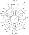
FIG. 2 is a plan view of a stator core according to the embodiment of the present invention. -
FIG. 3 is an explanatory view showing a corresponding relationship between a shape of the stator core and a shape of a bobbin according to the embodiment of the present invention. -
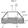
FIG. 4 is a cross-sectional view of the stator core according to the embodiment of the present invention when seen in a radial direction with respect to an axis. - A
compressor 10 according to an embodiment of the present invention will be described with reference toFIGS. 1 to 4 . In addition, the expressions "the same" and "parallel" used in the following do not mean strictly parallel or only the same, but substantially the same or substantially parallel, design tolerances and manufacturing errors are acceptable. - As shown in
FIG. 1 , acompressor system 100 according to the embodiment includes anaccumulator 24,suction pipes first suction pipe 26A and asecond suction pipe 26B), and acompressor 10. Thecompressor 10 is a two-cylinder type rotary compressor. Thecompressor 10 includes amotor 18 driven by an external power supply, and acompression mechanism portion 10A which is driven by themotor 18 and generates a compressed refrigerant (fluid), and ahousing 11 which covers themotor 18 and thecompression mechanism portion 10A. - The
compression mechanism portion 10A includes acrankshaft 16 rotated by themotor 18,piston rotors first piston rotor 13A and asecond piston rotor 13B) which eccentrically rotate in accordance with rotation of thecrankshaft 16, andcylinders first cylinder 12A and asecond cylinder 12B) in which compression chambers for accommodating thepiston rotors - In the
compression mechanism portion 10A, the disk-shapedfirst cylinder 12A andsecond cylinder 12B are provided in two upper and lower stages in thecylindrical housing 11. Thehousing 11 forms a discharge space V, in which the compressed refrigerant is discharged, by surrounding thefirst cylinder 12A and thesecond cylinder 12B. The cylindricalfirst piston rotors 13A andsecond piston rotors 13B each having an external form smaller than an inside between inner wall surfaces of each of thefirst cylinder 12A and thesecond cylinder 12B are disposed inside thefirst cylinder 12A and thesecond cylinder 12B. Thefirst piston rotor 13A and thesecond piston rotor 13B are respectively inserted and fixed intoeccentric shaft portions - Phases of the
first piston rotor 13A of the upper cylinder and thesecond piston rotor 13B of the lower cylinder are different from each other by 180°. A disk-shaped partition plate 15 is provided between the upperfirst cylinder 12A and the lowersecond cylinder 12B. A space R in the upperfirst cylinder 12A and a space R in the lowersecond cylinder 12B do not communicate with each other and are partitioned into an upper compression chamber R1 and a lower compression chamber R2 by thepartition plate 15. - The
crankshaft 16 is supported rotatably around an axis O by an upper bearingportion 17A fixed to thefirst cylinder 12A and alower bearing portion 17B fixed to thesecond cylinder 12B. Thecrankshaft 16 haseccentric shaft portions crankshaft 16. When theeccentric shaft portions crankshaft 16, the upperfirst piston rotor 13A and the lowersecond piston rotors 13B follow this turning and eccentrically rotate in thefirst cylinder 12A and thesecond cylinder 12B, respectively. - The
crankshaft 16 protrudes upward from the upper bearingportion 17A (that is, in a direction in which themotor 18 is located when seen from thecompression mechanism portion 10A). Arotor 19A of themotor 18 for rotationally driving thecrankshaft 16 is integrally provided at a portion of thecrankshaft 16 which protrudes upward from the upper bearingportion 17A. Astator 19B is fixed to an inner peripheral surface of thehousing 11 to face an outer peripheral portion of therotor 19A. - In the
compressor 10, theaccumulator 24 for gas-liquid separation of the refrigerant prior to supply to thecompressor 10 is fixed to thehousing 11 via astay 25. A refrigerant before compression is stored in theaccumulator 24. Thefirst suction pipe 26A and thesecond suction pipe 26B for suctioning the refrigerant in theaccumulator 24 to thecompressor 10 are provided between theaccumulator 24 and thecompressor 10. One ends of thefirst suction pipe 26A and thesecond suction pipe 26B are connected to a lower portion of theaccumulator 24. The other ends of thefirst suction pipe 26A and thesecond suction pipe 26B are respectively connected tosuction ports first suction port 23A and asecond suction port 23B) formed in thefirst cylinder 12A and thesecond cylinder 12B throughopenings first opening 22A and asecond opening 22B) formed in thehousing 11. - The
compressor 10 introduces the refrigerant from aninlet 24a of theaccumulator 24 to the inside of theaccumulator 24. Specifically, the refrigerant is separated into gas and liquid in theaccumulator 24. The separated gas phase is supplied from thefirst suction pipe 26A and thesecond suction pipe 26B to the compression chambers R1 and R2, which are internal spaces of thefirst cylinder 12A and thesecond cylinder 12B, through thefirst suction port 23A and thesecond suction port 23B. - Volumes of the compression chambers R1 and R2 are gradually decreased and the refrigerant is compressed by eccentrically rotating the
first piston rotor 13A and thesecond piston rotor 13B. The refrigerant passes around themotor 18 and is then discharged to apipe 27 constituting a refrigeration cycle via an outlet provided at the top. - The
motor 18 includes therotor 19A which is rotatable around the axis O, and thestator 19B which surrounds therotor 19A from an outer peripheral side thereof around the axis O. Therotor 19A is provided at an upper end of thecrankshaft 16. Therotor 19A has a permanent magnet therein, and an outer shape thereof has a substantially cylindrical shape centered on the axis O. - As shown in
FIGS. 2 to 4 , thestator 19B includes astator core 20, abobbin 30, and acoil 40. Thestator core 20 is formed by stacking plate-shapedelectromagnetic steel plates 21 expanding in a plane orthogonal to the axis O. - As shown in
FIG. 2 , thestator core 20 includes anannular yoke 20A centered on the axis O, and a plurality of (nine)teeth 20B formed to project from an inner peripheral surface of theyoke 20A. Theyoke 20A is formed in a regular polygonal shape when seen in a direction of the axis O. Theyoke 20A in the embodiment is formed in a regular nonagonal shape. Each apex angle of theyoke 20A is chamfered in an arc shape to fit on the inner peripheral surface of thehousing 11. The chamfered portions are fitted to the inner peripheral surface of thehousing 11. - The plurality of
teeth 20B protrude from the inner peripheral surface of theyoke 20A at intervals in a circumferential direction about the axis O. As shown inFIGS. 2 and3 , theteeth 20B includes toothmain bodies 201B,flange portions 202B, firstcurved portions 203B, and secondcurved portions 204B. - The tooth
main body 201B extends inward in a radial direction about the axis O with respect to the inner peripheral surface of theyoke 20A. The toothmain body 201B has a constant length in the circumferential direction to form a linear shape when seen in the direction of the axis O. - The
flange portion 202B is provided radially inward with respect to the toothmain body 201B. When theflange portion 202B is seen in the direction of the axis O, a length in the circumferential direction is longer than that of the toothmain body 201B. - The first
curved portion 203B connects the toothmain body 201B to theyoke 20A. The firstcurved portion 203B has a first curved surface S1 which is curved so that the dimension in the circumferential direction gradually increases from the toothmain body 201B toward theyoke 20A when seen in the direction of the axis O. The toothmain body 201B and theyoke 20A are connected by the firstcurved portion 203B in a state in which an angle R is formed. - The second
curved portion 204B connects the toothmain body 201B to theflange portion 202B. The secondcurved portion 204B has a second curved surface S2 which is curved so that the length in the circumferential direction gradually increases from the toothmain body 201B toward theflange portion 202B when seen in the direction of the axis O. The toothmain body 201B and theflange portion 202B are connected by the second curved surface S2 in a state in which an angle R is formed. - The first
curved portion 203B and the secondcurved portion 204B are non-constant width portions in each of theteeth 20B. The non-constant width portion is a region in therespective teeth 20B in which the length in the circumferential direction differs depending on a position in the radial direction. On the other hand, the toothmain body 201B is a constant width portion in each of theteeth 20B. The constant width portion is a region in therespective teeth 20B in which the length in the circumferential direction is constant at any position in the radial direction. - The
bobbin 30 is a member formed of a resin and provided for holding the winding such that it does not become detached from thestator core 20 when thecoil 40 described later is formed. Thebobbin 30 is provided on eachmain surface 20a of thestator core 20. Themain surfaces 20a are surfaces of thestator core 20 facing in the direction of the axis O. That is, themain surfaces 20a are surfaces on both sides of thestator core 20 in the direction of the axis O. A pair ofbobbins 30 have the same constitution. Therefore, hereinafter, only thebobbin 30 located on one side (upper side) in the direction of the axis O will be described. - As shown in
FIG. 3 or4 , thebobbin 30 includes an arc-shapedouter edge portion 30A and aninner edge portion 30B centered on the axis O, and a plurality of bobbin base portions (support portions) 30C which connect theouter edge portion 30A to theinner edge portion 30B in the radial direction. - The
outer edge portion 30A and theinner edge portion 30B have a plate shape extending from themain surface 20a toward one side in the direction of the axis O. A diameter of theouter edge portion 30A is larger than a diameter of theinner edge portion 30B. - The
bobbin base portion 30C extends in the radial direction to correspond to therespective teeth 20B when seen in the direction of the axis O. Thebobbin base portion 30C connects theouter edge portion 30A to theinner edge portion 30B. A surface of thebobbin base portion 30C facing one side in the direction of the axis O (a surface opposite to a surface facing themain surface 20a in the direction of the axis O) is asupport surface 30a which supports the winding of thecoil 40. That is, thebobbin base portion 30C is a region of thebobbin 30 in which the winding is wound. Thebobbin base portion 30C includes a basemain body 35 and a windinglength adjustment portion 36. - The base
main body 35 is formed at a position corresponding to (overlapping) the toothmain body 201B when viewed in the direction of the axis O. The basemain body 35 is formed so that a winding length, which is a length of the winding of the portion wound around thebobbin base portion 30C per one turn of the winding, is constant at any position in the radial direction. The basemain body 35 is formed so that a length between themain surface 20a and thesupport surface 30a in the direction of the axis O does not change. Specifically, the basemain body 35 extends in the radial direction so that lengths in the circumferential direction and the direction of the axis O are constant. As thesupport surface 30a, abase surface 33a parallel to themain surface 20a is formed on the basemain body 35. - The winding
length adjustment portion 36 is formed at a position corresponding to (overlapping) each of the firstcurved portion 203B and the secondcurved portion 204B when seen in the direction of the axis O. That is, the windinglength adjustment portion 36 is formed on both sides of the basemain body 35 and connect the basemain body 35 to theouter edge portion 30A and theinner edge portion 30B. The windinglength adjustment portion 36 is formed to reduce the winding length as a length of therespective teeth 20B in the circumferential direction increases and to increase the winding length as the length of therespective teeth 20B in the circumferential direction decreases. Specifically, the windinglength adjustment portion 36 is formed to have a constant length in the circumferential direction. The windinglength adjustment portion 36 is formed so that the dimension between themain surface 20a and thesupport surface 30a in the direction of the axis O changes. - A first
inclined surface 31a which is inclined with respect to themain surface 20a is formed as thesupport surface 30a of the windinglength adjustment portion 36 on the side corresponding to the firstcurved portion 203B in the radial direction. The firstinclined surface 31a is inclined to gradually separate from themain surface 20a as it goes from the outer side to the inner side in the radial direction. That is, the firstinclined surface 31a is a flat surface inclined to face the outer side in the radial direction when seen in the circumferential direction. - A second
inclined surface 32a which is inclined with respect to themain surface 20a is formed as thesupport surface 30a of the windinglength adjustment portion 36 on the side corresponding to the secondcurved portion 204B in the radial direction. The secondinclined surface 32a is inclined to become gradually closer to themain surface 20a as it goes from the outer side to the inner side in the radial direction. That is, the secondinclined surface 32a is a flat surface inclined to face the inner side in the radial direction when seen in the circumferential direction. - Accordingly, in the
bobbin base portion 30C, a height of thesupport surface 30a with respect to themain surface 20a is changed from the basemain body 35 to theouter edge portion 30A or theinner edge portion 30B by the windinglength adjustment portion 36. - The
coil 40 is formed by winding a winding around therespective teeth 20B and the respectivebobbin base portions 30C of the pair ofbobbins 30 as described above. That is, in the embodiment, ninecoils 40 are provided at intervals in the circumferential direction. More specifically, thecoil 40 has a plurality of turning portions Cr, each of which turns around a surface of therespective teeth 20B facing the one side in the circumferential direction, a surface thereof facing the other side, and thesupport surface 30a of each of the pair ofbobbin base portions 30C. The plurality of turning portions Cr are formed by one continuous winding. The plurality of turning portions Cr are arranged to be adjacent to therespective teeth 20B and thebobbin base portion 30C in the radial direction without gaps therebetween and form a layered winding layer. Thecoil 40 is formed by providing a plurality of winding layers on theteeth 20B and the pair ofbobbin base portions 30C. - As shown in
FIG. 4 , in the firstcurved portion 203B (the secondcurved portion 204B), the winding is wound to extend from a surface of thestator core 20 facing the one side in the circumferential direction to a surface of thestator core 20 facing the other side in the circumferential direction through the firstinclined surface 31a (the secondinclined surface 32a). - Here, as shown in
FIG. 3 , among the plurality of windings (the turning portions Cr) wound on the firstinclined surface 31a, a first outer turning portion Cr1 located at the outermost side in the radial direction is passes through a portion of the firstcurved portion 203B (the non-constant width portion) having the largest dimension in the circumferential direction. Therefore, a length of the winding in the circumferential direction when seen in the direction of the axis O is relatively long in the first outer turning portion Cr1, as compared to a first inner turning portion Cr2 located at the innermost side in the radial direction on the firstinclined surface 31a. However, the height of the firstinclined surface 31a with respect to themain surface 20a is the smallest at the outermost side of the windinglength adjustment portion 36 in the radial direction on the firstcurved portion 203B. Further, the height of the firstinclined surface 31a with respect to themain surface 20a is the largest at the innermost of the windinglength adjustment portion 36 in the radial direction on the firstcurved portion 203B. Thus, the length of the winding in the direction of the axis O when seen in the circumferential direction becomes shorter in the first outer turning portion Cr1 than in the first inner turning portion Cr2 by a difference in height of the firstinclined surface 31a. As a result, the winding length of the first outer turning portion Cr1 and the winding length of the first inner turning portion Cr2 are the same as each other. - Similarly, among the plurality of windings (the turning portions Cr) wound on the second
inclined surface 32a, a second inner turning portion Cr3 located at the innermost side in the radial direction is passes through a portion of the secondcurved portion 204B (the non-constant width portion) having the largest dimension in the circumferential direction. Therefore, a length of the winding in the circumferential direction when seen in the direction of the axis O is relatively long in the second inner turning portion Cr3, as compared to a second outer turning portion Cr4 located at the outermost side in the radial direction on the secondinclined surface 32a. However, the height of the secondinclined surface 32a with respect to themain surface 20a is the smallest at the innermost side of the windinglength adjustment portion 36 in the radial direction on the secondcurved portion 204B. Further, the height of the secondinclined surface 32a with respect to themain surface 20a is the largest at the outermost of the windinglength adjustment portion 36 in the radial direction on the secondcurved portion 204B. Thus, the length of the winding in the direction of the axis O when seen in the circumferential direction becomes shorter in the second inner turning portion Cr3 than in the second outer turning portion Cr4 by a difference in height of the secondinclined surface 32a. As a result, the winding length of the second outer turning portion Cr4 and the winding length of the second inner turning portion Cr3 are the same as each other. - As one of measures for improving efficiency of the
motor 18, it is conceivable to increase the number of windings wound on theteeth 20B. As a structure for that, for example, there is a structure in which an acute corner portion is formed at a connection portion between theyoke 20A and theteeth 20B in thestator core 20 to increase a radial length of therespective teeth 20B capable of winding the winding. However, when such a corner portion is formed, stress concentration occurs at the corner portion in a state in which thestator core 20 is fitted to the inner peripheral surface of thehousing 11. As a result, damage to thestator core 20 or iron loss of themotor 18 may occur, and thus the efficiency may be deteriorated. On the other hand, when theyoke 20A and theteeth 20B are connected in a curved shape such as the first curved surface S1 or the second curved surface S2, the stress concentration at the corner portion can be reduced. However, in the vicinity of the corner portion formed in the curved shape, the length in the circumferential direction increases, as compared to the toothmain body 201B. As a result, since the length or tension per one turn of the winding does not become constant, there is a possibility that winding loosening may occur during manufacturing. - However, in the embodiment, the winding
length adjustment portion 36 is formed corresponding to the firstcurved portion 203B and the secondcurved portion 204B. Therefore, the dimension between thesupport surface 30a and themain surface 20a (the dimension in the direction of the axis O) changes in accordance with a change in the dimension of therespective teeth 20B in circumferential direction. That is, a height of thesupport surface 30a with respect to themain surface 20a is relatively small at a portion of therespective teeth 20B in which the length in the circumferential direction is relatively large. On the other hand, the height of thesupport surface 30a with respect to themain surface 20a is relatively large at a portion of therespective teeth 20B in which the length in the circumferential direction is relatively small. Therefore, a length of the turning portion Cr in the radial direction can be reduced in a region ofrespective teeth 20B in which the dimension in the circumferential direction increases. Also, the length of the turning portion Cr in the radial direction can be increased in a region ofrespective teeth 20B in which the length in the circumferential direction descreases. In this way, the length of the winding of the portion wound on thebobbin base portion 30C can be constant simply by changing the height of thesupport surface 30a with respect to themain surface 20a. - Therefore, even when the region in which the dimension in the circumferential direction changes is formed in the
respective teeth 20B, the length of the winding per one turn can be kept constant, and the tension applied to the winding can be constant. Thus, it is possible to reduce the possibility of occurrence of the winding loosening and to manufacture thestator 19B more easily. Furthermore, the stress concentration can be reduced by forming the firstcurved portion 203B or the secondcurved portion 204B. Accordingly, it is possible to achieve both prevention of the damage to thestator core 20 and simplification of the manufacturing process by avoiding the winding loosening of the winding. Thus, thestator 19B can be easily manufactured while securing stable performance. - Accordingly, the
motor 18 which can be easily manufactured and has improved performance can be provided. Furthermore, the performance improvement of themotor 18 and thus the performance improvement of thecompressor 10 can be achieved. - Although the embodiment of the present invention have been described above in detail with reference to the drawings, each constitution in the embodiment and the combination thereof are one example, and addition, omission, substitution, and other modifications of the constitution are possible without departing from the spirit of the present invention. Further, the present invention is not limited by the embodiment, and is limited only by the scope of claims.
- The winding
length adjustment portion 36 is not limited to the structure in which the winding length is changed by the inclined surface as in the embodiment. As long as the windinglength adjustment portion 36 has a structure capable of changing the winding length, for example, a curved surface may be formed or a groove may be formed. - Moreover, in the above-described embodiment, the example in which the angles of the first
inclined surface 31a and the secondinclined surface 32a in thebobbin base portions 30C are constant over the entire region in the radial direction has been described. However, the aspect of the firstinclined surface 31a and the secondinclined surface 32a is not limited thereto. As another example, the firstinclined surface 31a may be formed so that the inclination angle partially increases or decreases from the outer side toward the inner side in the radial direction. Similarly, the secondinclined surface 32a may be formed so that the inclination angle partially increases or decreases from the outer side to the inner side in the radial direction. Furthermore, the firstinclined surface 31a and the secondinclined surface 32a may be three-dimensionally inclined to approach themain surface 20a as it goes outward in the circumferential direction as well as in the radial direction. - Further, in the above-described embodiment, an example in which the number of
teeth 20B in thestator core 20 is nine has been described. However, the number ofteeth 20B is not limited thereto and may be eight or less or ten or more. - According to the present invention, manufacture is able to be performed easily while securing stable performance.
-
- 100 Compressor system
- 10 Compressor
- 10A Compression mechanism portion
- 11 Housing
- 12A First cylinder (cylinder)
- 12B Second cylinder (cylinder)
- R1, R2 Compression chamber
- 13A First piston rotor (piston rotor)
- 13B Second piston rotor (piston rotor)
- 14A, 14B Eccentric shaft portion
- 16 Crankshaft
- 18 Motor
- 19A Rotor
- 19B Stator
- 20 Stator core
- 20a Main surface
- 20A Yoke
- 20B Teeth
- 201B Tooth main body
- 202B Flange portion
- 203B First curved portion
- S1 First curved surface
- 204B Second curved portion
- S2 Second curved surface
- 40 Coil
- 22A First opening (opening)
- 22B Second opening (opening)
- 23A First suction port (suction port)
- 23B Second suction port (suction port)
- 24 Accumulator
- 25 Stay
- 26A First suction pipe (suction pipe)
- 26B Second suction pipe (suction pipe)
- 27 Pipe
- 30 Bobbin
- 30a Support surface
- 30A Outer edge portion
- 30B Inner edge portion
- 30C Bobbin base portion
- 35 Base main body
- 36 Wiring length adjustment portion
- 31a First inclined surface
- 32a Second inclined surface
- Cr Turning portion
- Cr1 First outer turning portion
- Cr2 First inner turning portion
- Cr3 Second inner turning portion
- Cr4 Second outer turning portion
- O Axis
Claims (7)
- A stator (19B) comprising:a stator core (20) including an annular yoke (20A) centered on an axis (O), and a plurality of teeth (20B) protruding inward from an inner peripheral surface of the yoke (20A) in a radial direction centered on the axis (O);a bobbin (30) provided on main surfaces (20a) facing both sides in a direction of the axis (O) in which the axis extends in the respective teeth (20B); anda coil (40) having a winding wound on the teeth (20B) and the bobbin (30),wherein the respective teeth (20B) have a non-constant width portion (203B, 204B) of which a length in a circumferential direction around the axis (O) differs depending on a position in the radial direction,the bobbin (30) has a support portion (30C) having a support surface (30a) which supports the winding and faces in the direction of the axis, andthe support portion (30C) has a winding length adjustment portion (36) which is formed at a position corresponding to the non-constant width portion (203B, 204B) when seen in the direction of the axis (O), reduces a winding length which is a length of the winding around the support portion (30C) as a length of the respective teeth (20B) in the circumferential direction increases and increases the length as the length of the respective teeth (20B) in the circumferential direction decreases.
- The stator (19B) according to claim 1, wherein the winding length adjustment portion (36) is formed so that a length between the support surface (30a) and the main surface (20a) in the direction of the axis decreases as the length of the respective teeth (20B) in the circumferential direction increases and the length between the support surface (30a) and the main surface (20a) in the direction of the axis increases as the length of the respective teeth (20B) decrease.
- The stator (19B) according to claim 2, wherein, in the winding length adjustment portion (36), the support surface (30a) is an inclined surface (31a, 32a) which is inclined such that it approaches the main surface (20a) as the length of the respective teeth (20B) in the circumferential direction increases.
- The stator (19B) according to any one of claims 1 to 3,wherein the respective teeth (20B) includea tooth main body (201B) which has a constant length in the circumferential direction and extends in the radial direction, anda first curved portion (203B) which is the non-constant width portion and connects the tooth main body (201B) to the yoke (20A) in a curved surface (S1) in which a length in the circumferential direction gradually increases from the tooth main body (201B) toward the yoke (20A) when seen in the direction of the axis (O).
- The stator (19B) according to claim 4,wherein the respective teeth (20B) includea flange portion (202B) which is provided inward in the radial direction with respect to the tooth main body (201B) and in which the length in the circumferential direction is longer than the tooth main body (201B), anda second curved portion (204B) which is the non-constant width portion and connects the tooth main body (201B) to the flange portion (202B) in a curved surface (S2) in which a length in the circumferential direction gradually increases from the tooth main body (201B) toward the flange portion (202B) when seen in the direction of the axis (O).
- A motor (18) comprising:a rotor (19A) which is rotatable around an axis (O); andthe stator (19B) according to any one of claims 1 to 5 which surrounds the rotor (19A) from an outer peripheral side of the rotor (19A).
- A compressor (10) comprising:a motor (18) according to claim 6;a compression mechanism portion (10A) which is driven by the motor (18) to compress fluid; anda housing (11) which covers the motor (18) and the compression mechanism portion (10A).
Applications Claiming Priority (1)
| Application Number | Priority Date | Filing Date | Title |
|---|---|---|---|
| JP2018074089A JP7122145B2 (en) | 2018-04-06 | 2018-04-06 | Stator, Motor, and Compressor |
Publications (2)
| Publication Number | Publication Date |
|---|---|
| EP3550700A1 true EP3550700A1 (en) | 2019-10-09 |
| EP3550700B1 EP3550700B1 (en) | 2021-06-16 |
Family
ID=66092248
Family Applications (1)
| Application Number | Title | Priority Date | Filing Date |
|---|---|---|---|
| EP19167402.7A Active EP3550700B1 (en) | 2018-04-06 | 2019-04-04 | Stator, motor and compressor |
Country Status (2)
| Country | Link |
|---|---|
| EP (1) | EP3550700B1 (en) |
| JP (1) | JP7122145B2 (en) |
Citations (4)
| Publication number | Priority date | Publication date | Assignee | Title |
|---|---|---|---|---|
| JP2002247790A (en) | 2001-02-21 | 2002-08-30 | Moric Co Ltd | Structure and manufacturing method of stator coil of rotating filed type electric apparatus |
| US20030048023A1 (en) * | 2001-09-07 | 2003-03-13 | Kenji Nagai | Insulator for armature of dynamo-electric machine |
| EP1806822A1 (en) * | 2004-10-29 | 2007-07-11 | Toyota Jidosha Kabushiki Kaisha | Motor generator and automobile carrying the same |
| US20140145545A1 (en) * | 2012-11-27 | 2014-05-29 | Rbc Manufacturing Corporation | Wire guide for use in an electric machine |
Family Cites Families (2)
| Publication number | Priority date | Publication date | Assignee | Title |
|---|---|---|---|---|
| JP2008061443A (en) | 2006-09-01 | 2008-03-13 | Mitsuba Corp | Insulator and motor |
| JPWO2015093157A1 (en) | 2013-12-20 | 2017-03-16 | 日立オートモティブシステムズ株式会社 | Rotating electric machine |
-
2018
- 2018-04-06 JP JP2018074089A patent/JP7122145B2/en active Active
-
2019
- 2019-04-04 EP EP19167402.7A patent/EP3550700B1/en active Active
Patent Citations (4)
| Publication number | Priority date | Publication date | Assignee | Title |
|---|---|---|---|---|
| JP2002247790A (en) | 2001-02-21 | 2002-08-30 | Moric Co Ltd | Structure and manufacturing method of stator coil of rotating filed type electric apparatus |
| US20030048023A1 (en) * | 2001-09-07 | 2003-03-13 | Kenji Nagai | Insulator for armature of dynamo-electric machine |
| EP1806822A1 (en) * | 2004-10-29 | 2007-07-11 | Toyota Jidosha Kabushiki Kaisha | Motor generator and automobile carrying the same |
| US20140145545A1 (en) * | 2012-11-27 | 2014-05-29 | Rbc Manufacturing Corporation | Wire guide for use in an electric machine |
Also Published As
| Publication number | Publication date |
|---|---|
| JP7122145B2 (en) | 2022-08-19 |
| JP2019187045A (en) | 2019-10-24 |
| EP3550700B1 (en) | 2021-06-16 |
Similar Documents
| Publication | Publication Date | Title |
|---|---|---|
| US8410655B2 (en) | Stator, motor, and compressor | |
| US10749388B2 (en) | Stator, motor, compressor, and refrigeration air conditioner | |
| JP5478461B2 (en) | Electric motor and compressor | |
| US10432050B2 (en) | Motor rotor, and compressor motor and compressor incorporated with the motor rotor | |
| US20140175930A1 (en) | Permanent magnet embedded type rotating electrical machine | |
| US10833544B2 (en) | Stator, motor, compressor, and refrigeration air conditioner | |
| JP2008211873A (en) | Stator, motor and compressor | |
| US8926295B2 (en) | Compressor | |
| JPWO2016203563A1 (en) | Rotor, permanent magnet embedded electric motor for compressor, compressor, and refrigeration cycle apparatus | |
| US20210222922A1 (en) | Electric motor and compressor having the same | |
| US20170074264A1 (en) | Electric pump | |
| JP2011015499A (en) | Rotor of electric motor | |
| AU2018306257B2 (en) | Compressor | |
| EP3550700B1 (en) | Stator, motor and compressor | |
| JP5862332B2 (en) | Rotor and compressor | |
| KR20200087601A (en) | Motor and compressor having thereof | |
| JP7317525B2 (en) | electric compressor | |
| JP7584682B2 (en) | Rotary Compressor | |
| JP2018102039A (en) | Electric motor rotor, compressor | |
| EP4130478B1 (en) | Rotary compressor | |
| JP2012120365A (en) | Rotor, motor and compressor | |
| JP2007205227A (en) | Compressor | |
| JP2011015500A (en) | Rotor of electric motor | |
| JP2008022666A (en) | Motor and compressor | |
| JP2012139045A (en) | Rotor, motor, and compressor |
Legal Events
| Date | Code | Title | Description |
|---|---|---|---|
| PUAI | Public reference made under article 153(3) epc to a published international application that has entered the european phase |
Free format text: ORIGINAL CODE: 0009012 |
|
| STAA | Information on the status of an ep patent application or granted ep patent |
Free format text: STATUS: THE APPLICATION HAS BEEN PUBLISHED |
|
| AK | Designated contracting states |
Kind code of ref document: A1 Designated state(s): AL AT BE BG CH CY CZ DE DK EE ES FI FR GB GR HR HU IE IS IT LI LT LU LV MC MK MT NL NO PL PT RO RS SE SI SK SM TR |
|
| AX | Request for extension of the european patent |
Extension state: BA ME |
|
| STAA | Information on the status of an ep patent application or granted ep patent |
Free format text: STATUS: REQUEST FOR EXAMINATION WAS MADE |
|
| 17P | Request for examination filed |
Effective date: 20200407 |
|
| RBV | Designated contracting states (corrected) |
Designated state(s): AL AT BE BG CH CY CZ DE DK EE ES FI FR GB GR HR HU IE IS IT LI LT LU LV MC MK MT NL NO PL PT RO RS SE SI SK SM TR |
|
| STAA | Information on the status of an ep patent application or granted ep patent |
Free format text: STATUS: EXAMINATION IS IN PROGRESS |
|
| 17Q | First examination report despatched |
Effective date: 20200624 |
|
| RIC1 | Information provided on ipc code assigned before grant |
Ipc: H02K 7/14 20060101ALN20201217BHEP Ipc: H02K 3/52 20060101AFI20201217BHEP |
|
| GRAP | Despatch of communication of intention to grant a patent |
Free format text: ORIGINAL CODE: EPIDOSNIGR1 |
|
| STAA | Information on the status of an ep patent application or granted ep patent |
Free format text: STATUS: GRANT OF PATENT IS INTENDED |
|
| RIC1 | Information provided on ipc code assigned before grant |
Ipc: H02K 3/52 20060101AFI20210111BHEP Ipc: H02K 7/14 20060101ALN20210111BHEP |
|
| INTG | Intention to grant announced |
Effective date: 20210128 |
|
| GRAS | Grant fee paid |
Free format text: ORIGINAL CODE: EPIDOSNIGR3 |
|
| GRAA | (expected) grant |
Free format text: ORIGINAL CODE: 0009210 |
|
| STAA | Information on the status of an ep patent application or granted ep patent |
Free format text: STATUS: THE PATENT HAS BEEN GRANTED |
|
| AK | Designated contracting states |
Kind code of ref document: B1 Designated state(s): AL AT BE BG CH CY CZ DE DK EE ES FI FR GB GR HR HU IE IS IT LI LT LU LV MC MK MT NL NO PL PT RO RS SE SI SK SM TR |
|
| REG | Reference to a national code |
Ref country code: GB Ref legal event code: FG4D |
|
| REG | Reference to a national code |
Ref country code: CH Ref legal event code: EP |
|
| REG | Reference to a national code |
Ref country code: DE Ref legal event code: R096 Ref document number: 602019005322 Country of ref document: DE |
|
| REG | Reference to a national code |
Ref country code: AT Ref legal event code: REF Ref document number: 1403153 Country of ref document: AT Kind code of ref document: T Effective date: 20210715 |
|
| REG | Reference to a national code |
Ref country code: IE Ref legal event code: FG4D |
|
| REG | Reference to a national code |
Ref country code: LT Ref legal event code: MG9D |
|
| PG25 | Lapsed in a contracting state [announced via postgrant information from national office to epo] |
Ref country code: HR Free format text: LAPSE BECAUSE OF FAILURE TO SUBMIT A TRANSLATION OF THE DESCRIPTION OR TO PAY THE FEE WITHIN THE PRESCRIBED TIME-LIMIT Effective date: 20210616 Ref country code: LT Free format text: LAPSE BECAUSE OF FAILURE TO SUBMIT A TRANSLATION OF THE DESCRIPTION OR TO PAY THE FEE WITHIN THE PRESCRIBED TIME-LIMIT Effective date: 20210616 Ref country code: FI Free format text: LAPSE BECAUSE OF FAILURE TO SUBMIT A TRANSLATION OF THE DESCRIPTION OR TO PAY THE FEE WITHIN THE PRESCRIBED TIME-LIMIT Effective date: 20210616 Ref country code: BG Free format text: LAPSE BECAUSE OF FAILURE TO SUBMIT A TRANSLATION OF THE DESCRIPTION OR TO PAY THE FEE WITHIN THE PRESCRIBED TIME-LIMIT Effective date: 20210916 |
|
| REG | Reference to a national code |
Ref country code: AT Ref legal event code: MK05 Ref document number: 1403153 Country of ref document: AT Kind code of ref document: T Effective date: 20210616 |
|
| REG | Reference to a national code |
Ref country code: NL Ref legal event code: MP Effective date: 20210616 |
|
| PG25 | Lapsed in a contracting state [announced via postgrant information from national office to epo] |
Ref country code: RS Free format text: LAPSE BECAUSE OF FAILURE TO SUBMIT A TRANSLATION OF THE DESCRIPTION OR TO PAY THE FEE WITHIN THE PRESCRIBED TIME-LIMIT Effective date: 20210616 Ref country code: SE Free format text: LAPSE BECAUSE OF FAILURE TO SUBMIT A TRANSLATION OF THE DESCRIPTION OR TO PAY THE FEE WITHIN THE PRESCRIBED TIME-LIMIT Effective date: 20210616 Ref country code: LV Free format text: LAPSE BECAUSE OF FAILURE TO SUBMIT A TRANSLATION OF THE DESCRIPTION OR TO PAY THE FEE WITHIN THE PRESCRIBED TIME-LIMIT Effective date: 20210616 Ref country code: NO Free format text: LAPSE BECAUSE OF FAILURE TO SUBMIT A TRANSLATION OF THE DESCRIPTION OR TO PAY THE FEE WITHIN THE PRESCRIBED TIME-LIMIT Effective date: 20210916 Ref country code: GR Free format text: LAPSE BECAUSE OF FAILURE TO SUBMIT A TRANSLATION OF THE DESCRIPTION OR TO PAY THE FEE WITHIN THE PRESCRIBED TIME-LIMIT Effective date: 20210917 |
|
| PG25 | Lapsed in a contracting state [announced via postgrant information from national office to epo] |
Ref country code: SK Free format text: LAPSE BECAUSE OF FAILURE TO SUBMIT A TRANSLATION OF THE DESCRIPTION OR TO PAY THE FEE WITHIN THE PRESCRIBED TIME-LIMIT Effective date: 20210616 Ref country code: EE Free format text: LAPSE BECAUSE OF FAILURE TO SUBMIT A TRANSLATION OF THE DESCRIPTION OR TO PAY THE FEE WITHIN THE PRESCRIBED TIME-LIMIT Effective date: 20210616 Ref country code: ES Free format text: LAPSE BECAUSE OF FAILURE TO SUBMIT A TRANSLATION OF THE DESCRIPTION OR TO PAY THE FEE WITHIN THE PRESCRIBED TIME-LIMIT Effective date: 20210616 Ref country code: CZ Free format text: LAPSE BECAUSE OF FAILURE TO SUBMIT A TRANSLATION OF THE DESCRIPTION OR TO PAY THE FEE WITHIN THE PRESCRIBED TIME-LIMIT Effective date: 20210616 Ref country code: AT Free format text: LAPSE BECAUSE OF FAILURE TO SUBMIT A TRANSLATION OF THE DESCRIPTION OR TO PAY THE FEE WITHIN THE PRESCRIBED TIME-LIMIT Effective date: 20210616 Ref country code: SM Free format text: LAPSE BECAUSE OF FAILURE TO SUBMIT A TRANSLATION OF THE DESCRIPTION OR TO PAY THE FEE WITHIN THE PRESCRIBED TIME-LIMIT Effective date: 20210616 Ref country code: RO Free format text: LAPSE BECAUSE OF FAILURE TO SUBMIT A TRANSLATION OF THE DESCRIPTION OR TO PAY THE FEE WITHIN THE PRESCRIBED TIME-LIMIT Effective date: 20210616 Ref country code: NL Free format text: LAPSE BECAUSE OF FAILURE TO SUBMIT A TRANSLATION OF THE DESCRIPTION OR TO PAY THE FEE WITHIN THE PRESCRIBED TIME-LIMIT Effective date: 20210616 Ref country code: PT Free format text: LAPSE BECAUSE OF FAILURE TO SUBMIT A TRANSLATION OF THE DESCRIPTION OR TO PAY THE FEE WITHIN THE PRESCRIBED TIME-LIMIT Effective date: 20211018 |
|
| PG25 | Lapsed in a contracting state [announced via postgrant information from national office to epo] |
Ref country code: PL Free format text: LAPSE BECAUSE OF FAILURE TO SUBMIT A TRANSLATION OF THE DESCRIPTION OR TO PAY THE FEE WITHIN THE PRESCRIBED TIME-LIMIT Effective date: 20210616 |
|
| REG | Reference to a national code |
Ref country code: DE Ref legal event code: R097 Ref document number: 602019005322 Country of ref document: DE |
|
| PLBE | No opposition filed within time limit |
Free format text: ORIGINAL CODE: 0009261 |
|
| STAA | Information on the status of an ep patent application or granted ep patent |
Free format text: STATUS: NO OPPOSITION FILED WITHIN TIME LIMIT |
|
| PG25 | Lapsed in a contracting state [announced via postgrant information from national office to epo] |
Ref country code: DK Free format text: LAPSE BECAUSE OF FAILURE TO SUBMIT A TRANSLATION OF THE DESCRIPTION OR TO PAY THE FEE WITHIN THE PRESCRIBED TIME-LIMIT Effective date: 20210616 |
|
| 26N | No opposition filed |
Effective date: 20220317 |
|
| PG25 | Lapsed in a contracting state [announced via postgrant information from national office to epo] |
Ref country code: AL Free format text: LAPSE BECAUSE OF FAILURE TO SUBMIT A TRANSLATION OF THE DESCRIPTION OR TO PAY THE FEE WITHIN THE PRESCRIBED TIME-LIMIT Effective date: 20210616 |
|
| PG25 | Lapsed in a contracting state [announced via postgrant information from national office to epo] |
Ref country code: IT Free format text: LAPSE BECAUSE OF FAILURE TO SUBMIT A TRANSLATION OF THE DESCRIPTION OR TO PAY THE FEE WITHIN THE PRESCRIBED TIME-LIMIT Effective date: 20210616 |
|
| REG | Reference to a national code |
Ref country code: CH Ref legal event code: PL |
|
| REG | Reference to a national code |
Ref country code: BE Ref legal event code: MM Effective date: 20220430 |
|
| PG25 | Lapsed in a contracting state [announced via postgrant information from national office to epo] |
Ref country code: MC Free format text: LAPSE BECAUSE OF FAILURE TO SUBMIT A TRANSLATION OF THE DESCRIPTION OR TO PAY THE FEE WITHIN THE PRESCRIBED TIME-LIMIT Effective date: 20210616 Ref country code: LU Free format text: LAPSE BECAUSE OF NON-PAYMENT OF DUE FEES Effective date: 20220404 Ref country code: LI Free format text: LAPSE BECAUSE OF NON-PAYMENT OF DUE FEES Effective date: 20220430 Ref country code: CH Free format text: LAPSE BECAUSE OF NON-PAYMENT OF DUE FEES Effective date: 20220430 |
|
| PG25 | Lapsed in a contracting state [announced via postgrant information from national office to epo] |
Ref country code: BE Free format text: LAPSE BECAUSE OF NON-PAYMENT OF DUE FEES Effective date: 20220430 |
|
| REG | Reference to a national code |
Ref country code: DE Ref legal event code: R082 Ref document number: 602019005322 Country of ref document: DE Representative=s name: CBDL PATENTANWAELTE GBR, DE Ref country code: DE Ref legal event code: R082 Ref document number: 602019005322 Country of ref document: DE Representative=s name: CBDL PATENTANWAELTE EGBR, DE |
|
| PG25 | Lapsed in a contracting state [announced via postgrant information from national office to epo] |
Ref country code: IE Free format text: LAPSE BECAUSE OF NON-PAYMENT OF DUE FEES Effective date: 20220404 |
|
| PG25 | Lapsed in a contracting state [announced via postgrant information from national office to epo] |
Ref country code: HU Free format text: LAPSE BECAUSE OF FAILURE TO SUBMIT A TRANSLATION OF THE DESCRIPTION OR TO PAY THE FEE WITHIN THE PRESCRIBED TIME-LIMIT; INVALID AB INITIO Effective date: 20190404 |
|
| PG25 | Lapsed in a contracting state [announced via postgrant information from national office to epo] |
Ref country code: MK Free format text: LAPSE BECAUSE OF FAILURE TO SUBMIT A TRANSLATION OF THE DESCRIPTION OR TO PAY THE FEE WITHIN THE PRESCRIBED TIME-LIMIT Effective date: 20210616 Ref country code: CY Free format text: LAPSE BECAUSE OF FAILURE TO SUBMIT A TRANSLATION OF THE DESCRIPTION OR TO PAY THE FEE WITHIN THE PRESCRIBED TIME-LIMIT Effective date: 20210616 |
|
| PG25 | Lapsed in a contracting state [announced via postgrant information from national office to epo] |
Ref country code: MT Free format text: LAPSE BECAUSE OF FAILURE TO SUBMIT A TRANSLATION OF THE DESCRIPTION OR TO PAY THE FEE WITHIN THE PRESCRIBED TIME-LIMIT Effective date: 20210616 |
|
| PGFP | Annual fee paid to national office [announced via postgrant information from national office to epo] |
Ref country code: DE Payment date: 20250305 Year of fee payment: 7 |
|
| PG25 | Lapsed in a contracting state [announced via postgrant information from national office to epo] |
Ref country code: TR Free format text: LAPSE BECAUSE OF FAILURE TO SUBMIT A TRANSLATION OF THE DESCRIPTION OR TO PAY THE FEE WITHIN THE PRESCRIBED TIME-LIMIT Effective date: 20210616 |
|
| PGFP | Annual fee paid to national office [announced via postgrant information from national office to epo] |
Ref country code: GB Payment date: 20260313 Year of fee payment: 8 |
|
| PGFP | Annual fee paid to national office [announced via postgrant information from national office to epo] |
Ref country code: FR Payment date: 20260309 Year of fee payment: 8 |