EP3550675A1 - Electrical connector with connector lock - Google Patents
Electrical connector with connector lock Download PDFInfo
- Publication number
- EP3550675A1 EP3550675A1 EP19164037.4A EP19164037A EP3550675A1 EP 3550675 A1 EP3550675 A1 EP 3550675A1 EP 19164037 A EP19164037 A EP 19164037A EP 3550675 A1 EP3550675 A1 EP 3550675A1
- Authority
- EP
- European Patent Office
- Prior art keywords
- connector
- arcuate
- protrusion
- latch
- accordance
- Prior art date
- Legal status (The legal status is an assumption and is not a legal conclusion. Google has not performed a legal analysis and makes no representation as to the accuracy of the status listed.)
- Granted
Links
Images


Classifications
-
- H—ELECTRICITY
- H01—ELECTRIC ELEMENTS
- H01R—ELECTRICALLY-CONDUCTIVE CONNECTIONS; STRUCTURAL ASSOCIATIONS OF A PLURALITY OF MUTUALLY-INSULATED ELECTRICAL CONNECTING ELEMENTS; COUPLING DEVICES; CURRENT COLLECTORS
- H01R13/00—Details of coupling devices of the kinds covered by groups H01R12/70 or H01R24/00 - H01R33/00
- H01R13/62—Means for facilitating engagement or disengagement of coupling parts or for holding them in engagement
- H01R13/639—Additional means for holding or locking coupling parts together, after engagement, e.g. separate keylock, retainer strap
-
- H—ELECTRICITY
- H01—ELECTRIC ELEMENTS
- H01R—ELECTRICALLY-CONDUCTIVE CONNECTIONS; STRUCTURAL ASSOCIATIONS OF A PLURALITY OF MUTUALLY-INSULATED ELECTRICAL CONNECTING ELEMENTS; COUPLING DEVICES; CURRENT COLLECTORS
- H01R13/00—Details of coupling devices of the kinds covered by groups H01R12/70 or H01R24/00 - H01R33/00
- H01R13/62—Means for facilitating engagement or disengagement of coupling parts or for holding them in engagement
- H01R13/627—Snap or like fastening
- H01R13/6271—Latching means integral with the housing
- H01R13/6273—Latching means integral with the housing comprising two latching arms
-
- H—ELECTRICITY
- H01—ELECTRIC ELEMENTS
- H01R—ELECTRICALLY-CONDUCTIVE CONNECTIONS; STRUCTURAL ASSOCIATIONS OF A PLURALITY OF MUTUALLY-INSULATED ELECTRICAL CONNECTING ELEMENTS; COUPLING DEVICES; CURRENT COLLECTORS
- H01R13/00—Details of coupling devices of the kinds covered by groups H01R12/70 or H01R24/00 - H01R33/00
- H01R13/62—Means for facilitating engagement or disengagement of coupling parts or for holding them in engagement
- H01R13/627—Snap or like fastening
- H01R13/6271—Latching means integral with the housing
- H01R13/6272—Latching means integral with the housing comprising a single latching arm
-
- H—ELECTRICITY
- H01—ELECTRIC ELEMENTS
- H01R—ELECTRICALLY-CONDUCTIVE CONNECTIONS; STRUCTURAL ASSOCIATIONS OF A PLURALITY OF MUTUALLY-INSULATED ELECTRICAL CONNECTING ELEMENTS; COUPLING DEVICES; CURRENT COLLECTORS
- H01R13/00—Details of coupling devices of the kinds covered by groups H01R12/70 or H01R24/00 - H01R33/00
- H01R13/62—Means for facilitating engagement or disengagement of coupling parts or for holding them in engagement
- H01R13/627—Snap or like fastening
- H01R13/6278—Snap or like fastening comprising a pin snapping into a recess
-
- H—ELECTRICITY
- H01—ELECTRIC ELEMENTS
- H01R—ELECTRICALLY-CONDUCTIVE CONNECTIONS; STRUCTURAL ASSOCIATIONS OF A PLURALITY OF MUTUALLY-INSULATED ELECTRICAL CONNECTING ELEMENTS; COUPLING DEVICES; CURRENT COLLECTORS
- H01R13/00—Details of coupling devices of the kinds covered by groups H01R12/70 or H01R24/00 - H01R33/00
- H01R13/62—Means for facilitating engagement or disengagement of coupling parts or for holding them in engagement
- H01R13/629—Additional means for facilitating engagement or disengagement of coupling parts, e.g. aligning or guiding means, levers, gas pressure electrical locking indicators, manufacturing tolerances
- H01R13/633—Additional means for facilitating engagement or disengagement of coupling parts, e.g. aligning or guiding means, levers, gas pressure electrical locking indicators, manufacturing tolerances for disengagement only
- H01R13/635—Additional means for facilitating engagement or disengagement of coupling parts, e.g. aligning or guiding means, levers, gas pressure electrical locking indicators, manufacturing tolerances for disengagement only by mechanical pressure, e.g. spring force
-
- H—ELECTRICITY
- H01—ELECTRIC ELEMENTS
- H01R—ELECTRICALLY-CONDUCTIVE CONNECTIONS; STRUCTURAL ASSOCIATIONS OF A PLURALITY OF MUTUALLY-INSULATED ELECTRICAL CONNECTING ELEMENTS; COUPLING DEVICES; CURRENT COLLECTORS
- H01R2107/00—Four or more poles
Definitions
- This disclosure generally relates to an electrical connector, and more particularly relates to an electrical connector with a connector lock.
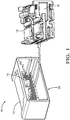
- Fig. 1 is an exploded-view illustrating a connector assembly 10, hereafter referred to as the assembly 10.
- the assembly 10 includes a first-connector 12 having a locking-lug 14 and a second-connector 16 configured to mate with the first-connector 12.
- the first-connector 12 and the second-connector 16 are formed of a polymeric dielectric material.
- the dielectric material may be any dielectric material capable of electrically isolating portions of electrical-terminals (not specifically shown) retained by the first-connector 12 and the second-connector 16, and is preferably a polyamide (NYLON) material.
- the first-connector 12 and/or the second-connector 16 connector may also be formed the polymeric material comprising at least 33% glass-fill.
- the first-connector 12 and the second-connector 16 are configured to be attached to wire cables (not shown) that may be a component of a wiring-harness of a vehicle.
- the second-connector 16 includes a cantilevered latch 18 configured to slideably engage the locking-lug 14 when the first-connector 12 is moved from an unmated-position 20 to a mated-position 22 (see Figs. 5A-5C ).
- Fig. 2 is a perspective-view of the second-connector 16 isolated from the assembly 10 illustrating an outer-surface 24 of the second-connector 16.
- the cantilevered latch 18 generally has an H-shape and includes a pair of parallel latch-arms 26 extending from a base 28 that is attached to the outer-surface 24.
- the pair of parallel latch-arms 26 overlay the outer-surface 24 and extend along a longitudinal-axis 30 of the second-connector 16 terminating at a first cross-beam 32 that spans the pair of parallel latch-arms 26.
- the cantilevered latch 18 also includes a second cross-beam 34 parallel to the first cross-beam 32 that is positioned between the base 28 and the first cross-beam 32, wherein the second cross-beam 34 is configured to releasably lock the locking-lug 14 when the first-connector 12 is in the mated-position 22.
- Fig. 3 is a section-view of the cantilevered latch 18 along the longitudinal-axis 30 through both the first cross-beam 32 and the second cross-beam 34.
- Each of the pair of parallel latch-arms 26 includes a rib 36 extending beyond a bottom-surface 38 of each individual latch-arm 26 from the base 28 to the first cross-beam 32.
- the rib 36 defines a first arcuate-protrusion 40 (i.e., the larger peak) and a second arcuate-protrusion 42 (i.e., the smaller peak), wherein the first arcuate-protrusion 40 is located proximate the first cross-beam 32 and the second arcuate-protrusion 42 is located proximate the second cross-beam 34.
- proximate includes distances between components of less than 10.0 mm.
- the first arcuate-protrusion 40 defines a first-distance 44 from the bottom-surface 38 and the second arcuate-protrusion 42 defines a second-distance 46 from the bottom-surface 38, with first-distance 44 being greater than the second-distance 46.
- the first arcuate-protrusion 40 defines a first-radius 48 in a range between 2.0 mm and 5.0 mm
- the second arcuate-protrusion 42 defines a second-radius 50 a range between 3.0 mm and 6.0 mm.
- Fig. 4 is a partial end-view of the second-connector 16 with the first cross-beam 32 in the foreground and illustrates the features of the cantilevered latch 18.
- the rib 36 at the base 28 of the cantilevered latch 18 has a first-thickness 58 in a range between 1.0 mm and 1.2 mm, and has a second-thickness 60 at the first arcuate-protrusion 40 is in a range between 0.7 mm and 0.8 mm.
- the pair of parallel latch-arms 26 define opposed ramps 52 formed into medial portions of the parallel latch-arms 26 and are configured to engage the locking-lug 14 during the mating sequence of the first-connector 12 with the second-connector 16.
- the opposed ramps 52 extend from the base 28 and terminate at the second cross-beam 34, and are characterized as having a ramp-angle 54 that is in a range between 15-degrees and 20-degrees.
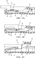
- Figs. 5A-5C illustrate three segments of the mating sequence as the first-connector 12 is moved from the unmated-position 20 to the mated-position 22. Only the locking-lug 14 of the first-connector 12 is shown in contact with the cantilevered latch 18 for clarity. The locking-lug 14 deflects the pair of parallel latch-arms 26 toward the outer-surface 24 of the second-connector 16 when first-connector 12 is moved from the unmated-position 20 to the mated-position 22.
- Fig 5A illustrates a starting point early in the mating sequence where the locking-lug 14 is deflecting the pair of parallel latch-arms 26 and the first arcuate-protrusion 40 contacts the outer-surface 24 before the second arcuate-protrusion 42 contacts the outer-surface 24 of the second-connector 16.
- Fig. 5B illustrates an intermediate point in the mating sequence where the locking-lug 14 overlays (i.e., is directly over) the second cross-beam 34 deflecting the pair of parallel latch-arms 26, whereby both the first arcuate-protrusion 40 and the second arcuate-protrusion 42 contact the outer-surface 24 thereby limiting the deflection of the pair of parallel latch-arms 26.
- This has the technical benefit of distributing a principal-stress within the pair of parallel latch-arms 26 between the base 28 and the first arcuate-protrusion 40 such that the principal-stress does not exceed a yield-strength of the at least 33% glass-filled polymeric dielectric material.
- the connector assembly 10 may achieve in excess of ten mating/unmating cycles without a failure of the cantilevered latch 18, which indicates up to a fivefold increase in the cyclic durability of the at least 33% glass-filled polymeric dielectric material.
- Fig. 5C illustrates the completion of the mating sequence in which the locking-lug 14 locked to the cantilevered latch 18 indicative of the first-connector 12 being in the mated-position 22, wherein neither the first arcuate-protrusion 40 nor the second arcuate-protrusion 42 contacts the outer-surface 24, thereby placing the cantilevered latch 18 in a stress-free or relaxed state.
- a connector assembly 10 (the assembly 10), is provided.
- the assembly 10 is an improvement over prior art connector assemblies because the assembly 10 may be formed of at least a 33% glass-filled polymeric dielectric material and exhibits improved cyclic durability test results.
- first contact could be termed a second contact
- second contact could be termed a first contact
- the first contact and the second contact are both contacts, but they are not the same contact.
- the terminology used in the description of the various described embodiments herein is for the purpose of describing particular embodiments only and is not intended to be limiting. As used in the description of the various described embodiments and the appended claims, the singular forms "a”, “an” and “the” are intended to include the plural forms as well, unless the context clearly indicates otherwise. It will also be understood that the term “and/or” as used herein refers to and encompasses any and all possible combinations of one or more of the associated listed items.
- the phrase “if it is determined” or “if [a stated condition or event] is detected” is, optionally, construed to mean “upon determining” or “in response to determining” or “upon detecting [the stated condition or event]” or “in response to detecting [the stated condition or event],” depending on the context.
Landscapes
- Details Of Connecting Devices For Male And Female Coupling (AREA)
Abstract
Description
- This disclosure generally relates to an electrical connector, and more particularly relates to an electrical connector with a connector lock.
- The present invention will now be described, by way of example with reference to the accompanying drawings, in which:
-
Fig. 1 is an exploded-view of a connector assembly in accordance with one embodiment; -
Fig. 2 is a perspective-view of a second-connector of the connector assembly ofFig. 1 in accordance with one embodiment; -
Fig. 3 is a section-view of a cantilevered latch of the second-connector ofFig. 2 in accordance with one embodiment; -
Fig. 4 is a portion of an end-view of the second-connector ofFig. 2 in accordance with one embodiment; -
Fig. 5A is a point in a mating sequence of the connector assembly ofFig. 1 in accordance with one embodiment; -
Fig. 5B is another point in the mating sequence of the connector assembly ofFig. 1 in accordance with one embodiment; and -
Fig. 5C is yet another point in the mating sequence of the connector assembly ofFig. 1 in accordance with one embodiment. - Reference will now be made in detail to embodiments, examples of which are illustrated in the accompanying drawings. In the following detailed description, numerous specific details are set forth in order to provide a thorough understanding of the various described embodiments. However, it will be apparent to one of ordinary skill in the art that the various described embodiments may be practiced without these specific details. In other instances, well-known methods, procedures, components, circuits, and networks have not been described in detail so as not to unnecessarily obscure aspects of the embodiments.
-
Fig. 1 is an exploded-view illustrating aconnector assembly 10, hereafter referred to as theassembly 10. Theassembly 10 includes a first-connector 12 having a locking-lug 14 and a second-connector 16 configured to mate with the first-connector 12. The first-connector 12 and the second-connector 16 are formed of a polymeric dielectric material. The dielectric material may be any dielectric material capable of electrically isolating portions of electrical-terminals (not specifically shown) retained by the first-connector 12 and the second-connector 16, and is preferably a polyamide (NYLON) material. The first-connector 12 and/or the second-connector 16 connector may also be formed the polymeric material comprising at least 33% glass-fill. The first-connector 12 and the second-connector 16 are configured to be attached to wire cables (not shown) that may be a component of a wiring-harness of a vehicle. The second-connector 16 includes acantilevered latch 18 configured to slideably engage the locking-lug 14 when the first-connector 12 is moved from an unmated-position 20 to a mated-position 22 (seeFigs. 5A-5C ). -
Fig. 2 is a perspective-view of the second-connector 16 isolated from theassembly 10 illustrating an outer-surface 24 of the second-connector 16. Thecantilevered latch 18 generally has an H-shape and includes a pair of parallel latch-arms 26 extending from abase 28 that is attached to the outer-surface 24. The pair of parallel latch-arms 26 overlay the outer-surface 24 and extend along a longitudinal-axis 30 of the second-connector 16 terminating at afirst cross-beam 32 that spans the pair of parallel latch-arms 26. Thecantilevered latch 18 also includes asecond cross-beam 34 parallel to thefirst cross-beam 32 that is positioned between thebase 28 and thefirst cross-beam 32, wherein thesecond cross-beam 34 is configured to releasably lock the locking-lug 14 when the first-connector 12 is in the mated-position 22. -
Fig. 3 is a section-view of thecantilevered latch 18 along the longitudinal-axis 30 through both thefirst cross-beam 32 and thesecond cross-beam 34. Each of the pair of parallel latch-arms 26 includes arib 36 extending beyond a bottom-surface 38 of each individual latch-arm 26 from thebase 28 to thefirst cross-beam 32. Therib 36 defines a first arcuate-protrusion 40 (i.e., the larger peak) and a second arcuate-protrusion 42 (i.e., the smaller peak), wherein the first arcuate-protrusion 40 is located proximate thefirst cross-beam 32 and the second arcuate-protrusion 42 is located proximate thesecond cross-beam 34. As used herein, the term "proximate" includes distances between components of less than 10.0 mm. The first arcuate-protrusion 40 defines a first-distance 44 from the bottom-surface 38 and the second arcuate-protrusion 42 defines a second-distance 46 from the bottom-surface 38, with first-distance 44 being greater than the second-distance 46. The first arcuate-protrusion 40 defines a first-radius 48 in a range between 2.0 mm and 5.0 mm, and the second arcuate-protrusion 42 defines a second-radius 50 a range between 3.0 mm and 6.0 mm. -
Fig. 4 is a partial end-view of the second-connector 16 with thefirst cross-beam 32 in the foreground and illustrates the features of thecantilevered latch 18. Therib 36 at thebase 28 of thecantilevered latch 18 has a first-thickness 58 in a range between 1.0 mm and 1.2 mm, and has a second-thickness 60 at the first arcuate-protrusion 40 is in a range between 0.7 mm and 0.8 mm. - Referring again to
Fig. 3 , the pair of parallel latch-arms 26 defineopposed ramps 52 formed into medial portions of the parallel latch-arms 26 and are configured to engage the locking-lug 14 during the mating sequence of the first-connector 12 with the second-connector 16. Theopposed ramps 52 extend from thebase 28 and terminate at thesecond cross-beam 34, and are characterized as having a ramp-angle 54 that is in a range between 15-degrees and 20-degrees. Experimentation by the inventors has discovered that the ramp-angle 54 in this range enables an engagement-force 56 (seeFigs 5A-5B ) exerted by thecantilevered latch 18 on the locking-lug 14, of less than 6 Newtons when the first-connector 12 is moved from the unmated-position 20 to the mated-position 22. -
Figs. 5A-5C illustrate three segments of the mating sequence as the first-connector 12 is moved from the unmated-position 20 to the mated-position 22. Only the locking-lug 14 of the first-connector 12 is shown in contact with thecantilevered latch 18 for clarity. The locking-lug 14 deflects the pair of parallel latch-arms 26 toward the outer-surface 24 of the second-connector 16 when first-connector 12 is moved from the unmated-position 20 to the mated-position 22. -
Fig 5A illustrates a starting point early in the mating sequence where the locking-lug 14 is deflecting the pair of parallel latch-arms 26 and the first arcuate-protrusion 40 contacts the outer-surface 24 before the second arcuate-protrusion 42 contacts the outer-surface 24 of the second-connector 16. -
Fig. 5B illustrates an intermediate point in the mating sequence where the locking-lug 14 overlays (i.e., is directly over) thesecond cross-beam 34 deflecting the pair of parallel latch-arms 26, whereby both the first arcuate-protrusion 40 and the second arcuate-protrusion 42 contact the outer-surface 24 thereby limiting the deflection of the pair of parallel latch-arms 26. This has the technical benefit of distributing a principal-stress within the pair of parallel latch-arms 26 between thebase 28 and the first arcuate-protrusion 40 such that the principal-stress does not exceed a yield-strength of the at least 33% glass-filled polymeric dielectric material. Experimentation by the inventors has discovered that theconnector assembly 10 may achieve in excess of ten mating/unmating cycles without a failure of the cantileveredlatch 18, which indicates up to a fivefold increase in the cyclic durability of the at least 33% glass-filled polymeric dielectric material. -
Fig. 5C illustrates the completion of the mating sequence in which the locking-lug 14 locked to thecantilevered latch 18 indicative of the first-connector 12 being in the mated-position 22, wherein neither the first arcuate-protrusion 40 nor the second arcuate-protrusion 42 contacts the outer-surface 24, thereby placing thecantilevered latch 18 in a stress-free or relaxed state. - Accordingly, a connector assembly 10 (the assembly 10), is provided. The
assembly 10 is an improvement over prior art connector assemblies because theassembly 10 may be formed of at least a 33% glass-filled polymeric dielectric material and exhibits improved cyclic durability test results. - While this invention has been described in terms of the preferred embodiments thereof, it is not intended to be so limited, but rather only to the extent set forth in the claims that follow. "One or more" includes a function being performed by one element, a function being performed by more than one element, e.g., in a distributed fashion, several functions being performed by one element, several functions being performed by several elements, or any combination of the above. It will also be understood that, although the terms first, second, etc. are, in some instances, used herein to describe various elements, these elements should not be limited by these terms. These terms are only used to distinguish one element from another. For example, a first contact could be termed a second contact, and, similarly, a second contact could be termed a first contact, without departing from the scope of the various described embodiments. The first contact and the second contact are both contacts, but they are not the same contact. The terminology used in the description of the various described embodiments herein is for the purpose of describing particular embodiments only and is not intended to be limiting. As used in the description of the various described embodiments and the appended claims, the singular forms "a", "an" and "the" are intended to include the plural forms as well, unless the context clearly indicates otherwise. It will also be understood that the term "and/or" as used herein refers to and encompasses any and all possible combinations of one or more of the associated listed items. It will be further understood that the terms "includes," "including," "comprises," and/or "comprising," when used in this specification, specify the presence of stated features, integers, steps, operations, elements, and/or components, but do not preclude the presence or addition of one or more other features, integers, steps, operations, elements, components, and/or groups thereof. As used herein, the term "if' is, optionally, construed to mean "when" or "upon" or "in response to determining" or "in response to detecting," depending on the context. Similarly, the phrase "if it is determined" or "if [a stated condition or event] is detected" is, optionally, construed to mean "upon determining" or "in response to determining" or "upon detecting [the stated condition or event]" or "in response to detecting [the stated condition or event]," depending on the context.
Claims (14)
- A connector assembly (10), comprising:a first-connector (12) having a locking-lug (14); anda second-connector (16) configured to mate with the first-connector (12), said second-connector (16) having a cantilevered latch (18) configured to slideably engage the locking-lug (14) when the first-connector (12) is moved from an unmated-position (20) to a mated-position (22), said cantilevered latch (18) generally having an H-shape and including a pair of parallel latch-arms (26) extending from a base (28), said base (28) attached to an outer-surface (24) of the second-connector (16), said pair of parallel latch-arms (26) overlaying the outer-surface (24) and extending along a longitudinal-axis (30) of the second-connector (16) and terminating at a first cross-beam (32) that spans the pair of parallel latch-arms (26), said cantilevered latch (18) further including a second cross-beam (34) parallel to the first cross-beam (32) and positioned between the base (28) and the first cross-beam (32), said second cross-beam (34) configured to releasably lock the locking-lug (14) when the first-connector (12) is in the mated-position (22), said pair of parallel latch-arms (26) including a rib (36) extending beyond a bottom-surface (38) of each individual latch-arm (26) from the base (28) to the first cross-beam (32), said rib (36) defining a first arcuate-protrusion (40) and a second arcuate-protrusion (42), said first arcuate-protrusion (40) located proximate the first cross-beam (32) and the second arcuate-protrusion (42) located proximate the second cross-beam (34), wherein the locking-lug (14) deflects the pair of parallel latch-arms (26) toward the outer-surface (24) of the second-connector (16) when the first-connector (12) is moved from the unmated-position (20) to the mated-position (22), whereby the first arcuate-protrusion (40) and the second arcuate-protrusion (42) contact the outer-surface (24) and limit a deflection of the pair of parallel latch-arms (26).
- The connector assembly (10) in accordance with claim 1, wherein the first arcuate-protrusion (40) contacts the outer-surface (24) before the second arcuate-protrusion (42) contacts the outer-surface (24) when the first-connector (12) is moved from the unmated-position (20) to the mated-position (22).
- The connector assembly (10) in accordance with claims 1 or 2, wherein both the first arcuate-protrusion (40) and the second arcuate-protrusion (42) are in contact with the outer-surface (24) when the locking-lug (14) overlays the second cross-beam (34).
- The connector assembly (10) in accordance with any one of the preceding claims, wherein neither the first arcuate-protrusion (40) nor the second arcuate-protrusion (42) contacts the outer-surface (24) when the first-connector (12) is in the mated-position (22).
- The connector assembly (10) in accordance with any one of the preceding claims, wherein the first arcuate-protrusion (40) defines a first-distance (44) from the bottom-surface (38) and the second arcuate-protrusion (42) defines a second-distance (46) from the bottom-surface (38), said first-distance (44) being greater than the second-distance (46).
- The connector assembly (10) in accordance with any one of the preceding claims, wherein the first arcuate-protrusion (40) defines a first-radius (48) and the second arcuate-protrusion (42) defines a second-radius (50).
- The connector assembly (10) in accordance with claim 6, wherein the first-radius (48) is in a range between 2.0 mm and 5.0 mm.
- The connector assembly (10) in accordance with claim 6 or 7, wherein the second-radius (50) is in a range between 3.0 mm and 6.0 mm.
- The connector assembly (10) in accordance with any one of the preceding claims, wherein the second-connector (16) is formed a polymeric material comprising at least 33% glass-fill.
- The connector assembly (10) in accordance with any one of the preceding claims, wherein the pair of parallel latch-arms (26) define opposed ramps (52) formed into medial portions of the pair of parallel latch-arms (26), said opposed ramps (52) configured to engage the locking-lug (14), said opposed ramps (52) extending from the base (28) and terminating at the second cross-beam (34).
- The connector assembly (10) in accordance with claim 10, wherein the opposed ramps (52) are characterized as having a ramp-angle (54) that is in a range between 15-degrees and 20-degrees.
- The connector assembly (10) in accordance with any one of the preceding claims, wherein a first-thickness (58) of the rib (36) at the base (28) is in a range between 1.0 mm and 1.2 mm.
- The connector assembly (10) in accordance with any one of the preceding claims, wherein a second-thickness (60) of the rib (36) at the first arcuate-protrusion (40) is in a range between 0.7 mm and 0.8 mm.
- The connector assembly (10) in accordance with any one of the preceding claims, wherein the cantilevered latch (18) exerts an engagement-force (56) on the locking-lug (14) of less than 6 Newtons when the first-connector (12) is moved from the unmated-position (20) to the mated-position (22).
Applications Claiming Priority (1)
| Application Number | Priority Date | Filing Date | Title |
|---|---|---|---|
| US15/946,343 US10186803B1 (en) | 2018-04-05 | 2018-04-05 | Electrical connector with connector lock |
Publications (2)
| Publication Number | Publication Date |
|---|---|
| EP3550675A1 true EP3550675A1 (en) | 2019-10-09 |
| EP3550675B1 EP3550675B1 (en) | 2021-06-16 |
Family
ID=65011554
Family Applications (1)
| Application Number | Title | Priority Date | Filing Date |
|---|---|---|---|
| EP19164037.4A Active EP3550675B1 (en) | 2018-04-05 | 2019-03-20 | Electrical connector with connector lock |
Country Status (4)
| Country | Link |
|---|---|
| US (1) | US10186803B1 (en) |
| EP (1) | EP3550675B1 (en) |
| KR (1) | KR102153346B1 (en) |
| CN (1) | CN110350362B (en) |
Cited By (1)
| Publication number | Priority date | Publication date | Assignee | Title |
|---|---|---|---|---|
| JP2024120458A (en) * | 2023-02-24 | 2024-09-05 | 矢崎総業株式会社 | connector |
Families Citing this family (1)
| Publication number | Priority date | Publication date | Assignee | Title |
|---|---|---|---|---|
| US11189953B2 (en) * | 2018-08-28 | 2021-11-30 | Aptiv Technologies Limited | Connector-assembly with primary-lock-reinforcement device |
Citations (3)
| Publication number | Priority date | Publication date | Assignee | Title |
|---|---|---|---|---|
| DE102010029192A1 (en) * | 2010-05-20 | 2011-11-24 | Tyco Electronics Amp Gmbh | Connector and plug-in module system |
| WO2015076378A1 (en) * | 2013-11-25 | 2015-05-28 | 矢崎総業株式会社 | Connector |
| US20170179643A1 (en) * | 2015-12-21 | 2017-06-22 | J.S.T. Corporation | Method of operating a connector latch |
Family Cites Families (19)
| Publication number | Priority date | Publication date | Assignee | Title |
|---|---|---|---|---|
| JP2596169Y2 (en) * | 1992-06-22 | 1999-06-07 | 矢崎総業株式会社 | Waterproof connector |
| JPH07307185A (en) * | 1994-05-11 | 1995-11-21 | Yazaki Corp | Connector locking device |
| JP3851746B2 (en) * | 1999-08-25 | 2006-11-29 | 住友電装株式会社 | connector |
| JP4047731B2 (en) | 2003-01-10 | 2008-02-13 | 三菱電線工業株式会社 | Electrical connector |
| JP2005166522A (en) * | 2003-12-04 | 2005-06-23 | Yazaki Corp | connector |
| JP4419875B2 (en) * | 2005-03-14 | 2010-02-24 | 住友電装株式会社 | Mating detection connector |
| US7232329B1 (en) * | 2006-07-05 | 2007-06-19 | Hon Hai Precision Ind. Co., Ltd. | Cable connector assembly with unitary latch |
| SG149732A1 (en) * | 2007-07-31 | 2009-02-27 | Mea Technologies Pte Ltd | Electric connector |
| JP5119909B2 (en) * | 2007-12-26 | 2013-01-16 | 住友電装株式会社 | connector |
| US8210864B1 (en) * | 2011-03-25 | 2012-07-03 | Delphi Technologies, Inc. | Connector terminal position assurance device |
| JP5814030B2 (en) * | 2011-07-27 | 2015-11-17 | 矢崎総業株式会社 | connector |
| KR101813746B1 (en) * | 2014-09-30 | 2018-01-02 | 롯데첨단소재(주) | A connector for electronic device, a connector for usb and usb memory device using thereof |
| JP5949970B1 (en) * | 2015-02-05 | 2016-07-13 | 第一精工株式会社 | Electrical connector |
| EP3089280A1 (en) * | 2015-04-29 | 2016-11-02 | Delphi International Operations Luxembourg S.à r.l. | Electrical connector system comprising a secondary locking device |
| JP2016212959A (en) * | 2015-04-29 | 2016-12-15 | 住友電装株式会社 | connector |
| CN204668603U (en) * | 2015-06-01 | 2015-09-23 | 深圳富明精密工业有限公司 | The steady type socket connector that contact engaging and separating force strengthens |
| JP6418101B2 (en) * | 2015-08-07 | 2018-11-07 | 株式会社オートネットワーク技術研究所 | Electrical connection device having fitting detection function |
| JP6213592B2 (en) * | 2016-02-25 | 2017-10-18 | 第一精工株式会社 | connector |
| CN205621949U (en) * | 2016-04-07 | 2016-10-05 | 进联电子科技(上海)有限公司 | Locking release of electric connection terminal |
-
2018
- 2018-04-05 US US15/946,343 patent/US10186803B1/en active Active
-
2019
- 2019-03-20 EP EP19164037.4A patent/EP3550675B1/en active Active
- 2019-03-26 KR KR1020190034030A patent/KR102153346B1/en active Active
- 2019-04-01 CN CN201910256648.8A patent/CN110350362B/en active Active
Patent Citations (3)
| Publication number | Priority date | Publication date | Assignee | Title |
|---|---|---|---|---|
| DE102010029192A1 (en) * | 2010-05-20 | 2011-11-24 | Tyco Electronics Amp Gmbh | Connector and plug-in module system |
| WO2015076378A1 (en) * | 2013-11-25 | 2015-05-28 | 矢崎総業株式会社 | Connector |
| US20170179643A1 (en) * | 2015-12-21 | 2017-06-22 | J.S.T. Corporation | Method of operating a connector latch |
Cited By (1)
| Publication number | Priority date | Publication date | Assignee | Title |
|---|---|---|---|---|
| JP2024120458A (en) * | 2023-02-24 | 2024-09-05 | 矢崎総業株式会社 | connector |
Also Published As
| Publication number | Publication date |
|---|---|
| US10186803B1 (en) | 2019-01-22 |
| KR20190116912A (en) | 2019-10-15 |
| EP3550675B1 (en) | 2021-06-16 |
| CN110350362A (en) | 2019-10-18 |
| CN110350362B (en) | 2020-10-20 |
| KR102153346B1 (en) | 2020-09-10 |
Similar Documents
| Publication | Publication Date | Title |
|---|---|---|
| US10498066B1 (en) | Connector assembly with terminal-stabilizer | |
| US20150333431A1 (en) | Connector assembly with male terminal protector | |
| US20100099288A1 (en) | Terminal assembly and sealed electrical connector | |
| US20230253735A1 (en) | Connector assembly with an unseated terminal detection feature | |
| US20200227842A1 (en) | Support barrel for an electrical lead | |
| US10186803B1 (en) | Electrical connector with connector lock | |
| US20160204539A1 (en) | Connector | |
| KR20080026045A (en) | Electrical connection system | |
| US5425660A (en) | Communications jack with improved comb | |
| US10741958B2 (en) | Connector with primary lock reinforcement | |
| EP3675286B1 (en) | Connector | |
| US10804637B2 (en) | Connector-assembly with primary-lock-reinforcement device having a shipping-position | |
| EP0975061A2 (en) | A watertight connector with inertial locking mechanism | |
| US7959465B2 (en) | Contact housing and electrical contact device | |
| US9954347B1 (en) | Wire harness assembly and seal retainer therefore | |
| US20210098924A1 (en) | Connector assembly | |
| US9219324B2 (en) | Plug connector having a first-mate grounding contact | |
| US20250019206A1 (en) | Elevator connector with alignment feature | |
| US20200076110A1 (en) | Connector-assembly with primary-lock-reinforcement device | |
| US10476207B2 (en) | Electrical distribution assembly | |
| US9647384B2 (en) | Back body for coaxial connector | |
| EP0726616A2 (en) | A pin coupling for the connection of co-axial cables | |
| CN116581580A (en) | Connector assembly with dislocating terminal detection function | |
| GB2577864A (en) | Connector | |
| HK1184597A1 (en) | Plugin connector and method for manufacture a plugin connector |
Legal Events
| Date | Code | Title | Description |
|---|---|---|---|
| PUAI | Public reference made under article 153(3) epc to a published international application that has entered the european phase |
Free format text: ORIGINAL CODE: 0009012 |
|
| STAA | Information on the status of an ep patent application or granted ep patent |
Free format text: STATUS: THE APPLICATION HAS BEEN PUBLISHED |
|
| AK | Designated contracting states |
Kind code of ref document: A1 Designated state(s): AL AT BE BG CH CY CZ DE DK EE ES FI FR GB GR HR HU IE IS IT LI LT LU LV MC MK MT NL NO PL PT RO RS SE SI SK SM TR |
|
| AX | Request for extension of the european patent |
Extension state: BA ME |
|
| STAA | Information on the status of an ep patent application or granted ep patent |
Free format text: STATUS: REQUEST FOR EXAMINATION WAS MADE |
|
| 17P | Request for examination filed |
Effective date: 20200408 |
|
| RBV | Designated contracting states (corrected) |
Designated state(s): AL AT BE BG CH CY CZ DE DK EE ES FI FR GB GR HR HU IE IS IT LI LT LU LV MC MK MT NL NO PL PT RO RS SE SI SK SM TR |
|
| GRAP | Despatch of communication of intention to grant a patent |
Free format text: ORIGINAL CODE: EPIDOSNIGR1 |
|
| STAA | Information on the status of an ep patent application or granted ep patent |
Free format text: STATUS: GRANT OF PATENT IS INTENDED |
|
| RIC1 | Information provided on ipc code assigned before grant |
Ipc: H01R 13/627 20060101AFI20210323BHEP Ipc: H01R 107/00 20060101ALN20210323BHEP |
|
| GRAS | Grant fee paid |
Free format text: ORIGINAL CODE: EPIDOSNIGR3 |
|
| INTG | Intention to grant announced |
Effective date: 20210412 |
|
| GRAA | (expected) grant |
Free format text: ORIGINAL CODE: 0009210 |
|
| STAA | Information on the status of an ep patent application or granted ep patent |
Free format text: STATUS: THE PATENT HAS BEEN GRANTED |
|
| AK | Designated contracting states |
Kind code of ref document: B1 Designated state(s): AL AT BE BG CH CY CZ DE DK EE ES FI FR GB GR HR HU IE IS IT LI LT LU LV MC MK MT NL NO PL PT RO RS SE SI SK SM TR |
|
| REG | Reference to a national code |
Ref country code: GB Ref legal event code: FG4D |
|
| REG | Reference to a national code |
Ref country code: CH Ref legal event code: EP |
|
| REG | Reference to a national code |
Ref country code: DE Ref legal event code: R096 Ref document number: 602019005312 Country of ref document: DE |
|
| REG | Reference to a national code |
Ref country code: AT Ref legal event code: REF Ref document number: 1403113 Country of ref document: AT Kind code of ref document: T Effective date: 20210715 |
|
| REG | Reference to a national code |
Ref country code: IE Ref legal event code: FG4D |
|
| REG | Reference to a national code |
Ref country code: LT Ref legal event code: MG9D |
|
| PG25 | Lapsed in a contracting state [announced via postgrant information from national office to epo] |
Ref country code: BG Free format text: LAPSE BECAUSE OF FAILURE TO SUBMIT A TRANSLATION OF THE DESCRIPTION OR TO PAY THE FEE WITHIN THE PRESCRIBED TIME-LIMIT Effective date: 20210916 Ref country code: LT Free format text: LAPSE BECAUSE OF FAILURE TO SUBMIT A TRANSLATION OF THE DESCRIPTION OR TO PAY THE FEE WITHIN THE PRESCRIBED TIME-LIMIT Effective date: 20210616 Ref country code: HR Free format text: LAPSE BECAUSE OF FAILURE TO SUBMIT A TRANSLATION OF THE DESCRIPTION OR TO PAY THE FEE WITHIN THE PRESCRIBED TIME-LIMIT Effective date: 20210616 Ref country code: FI Free format text: LAPSE BECAUSE OF FAILURE TO SUBMIT A TRANSLATION OF THE DESCRIPTION OR TO PAY THE FEE WITHIN THE PRESCRIBED TIME-LIMIT Effective date: 20210616 |
|
| REG | Reference to a national code |
Ref country code: AT Ref legal event code: MK05 Ref document number: 1403113 Country of ref document: AT Kind code of ref document: T Effective date: 20210616 |
|
| REG | Reference to a national code |
Ref country code: NL Ref legal event code: MP Effective date: 20210616 |
|
| PG25 | Lapsed in a contracting state [announced via postgrant information from national office to epo] |
Ref country code: RS Free format text: LAPSE BECAUSE OF FAILURE TO SUBMIT A TRANSLATION OF THE DESCRIPTION OR TO PAY THE FEE WITHIN THE PRESCRIBED TIME-LIMIT Effective date: 20210616 Ref country code: SE Free format text: LAPSE BECAUSE OF FAILURE TO SUBMIT A TRANSLATION OF THE DESCRIPTION OR TO PAY THE FEE WITHIN THE PRESCRIBED TIME-LIMIT Effective date: 20210616 Ref country code: NO Free format text: LAPSE BECAUSE OF FAILURE TO SUBMIT A TRANSLATION OF THE DESCRIPTION OR TO PAY THE FEE WITHIN THE PRESCRIBED TIME-LIMIT Effective date: 20210916 Ref country code: LV Free format text: LAPSE BECAUSE OF FAILURE TO SUBMIT A TRANSLATION OF THE DESCRIPTION OR TO PAY THE FEE WITHIN THE PRESCRIBED TIME-LIMIT Effective date: 20210616 Ref country code: GR Free format text: LAPSE BECAUSE OF FAILURE TO SUBMIT A TRANSLATION OF THE DESCRIPTION OR TO PAY THE FEE WITHIN THE PRESCRIBED TIME-LIMIT Effective date: 20210917 |
|
| PG25 | Lapsed in a contracting state [announced via postgrant information from national office to epo] |
Ref country code: SM Free format text: LAPSE BECAUSE OF FAILURE TO SUBMIT A TRANSLATION OF THE DESCRIPTION OR TO PAY THE FEE WITHIN THE PRESCRIBED TIME-LIMIT Effective date: 20210616 Ref country code: RO Free format text: LAPSE BECAUSE OF FAILURE TO SUBMIT A TRANSLATION OF THE DESCRIPTION OR TO PAY THE FEE WITHIN THE PRESCRIBED TIME-LIMIT Effective date: 20210616 Ref country code: NL Free format text: LAPSE BECAUSE OF FAILURE TO SUBMIT A TRANSLATION OF THE DESCRIPTION OR TO PAY THE FEE WITHIN THE PRESCRIBED TIME-LIMIT Effective date: 20210616 Ref country code: PT Free format text: LAPSE BECAUSE OF FAILURE TO SUBMIT A TRANSLATION OF THE DESCRIPTION OR TO PAY THE FEE WITHIN THE PRESCRIBED TIME-LIMIT Effective date: 20211018 Ref country code: CZ Free format text: LAPSE BECAUSE OF FAILURE TO SUBMIT A TRANSLATION OF THE DESCRIPTION OR TO PAY THE FEE WITHIN THE PRESCRIBED TIME-LIMIT Effective date: 20210616 Ref country code: AT Free format text: LAPSE BECAUSE OF FAILURE TO SUBMIT A TRANSLATION OF THE DESCRIPTION OR TO PAY THE FEE WITHIN THE PRESCRIBED TIME-LIMIT Effective date: 20210616 Ref country code: SK Free format text: LAPSE BECAUSE OF FAILURE TO SUBMIT A TRANSLATION OF THE DESCRIPTION OR TO PAY THE FEE WITHIN THE PRESCRIBED TIME-LIMIT Effective date: 20210616 Ref country code: EE Free format text: LAPSE BECAUSE OF FAILURE TO SUBMIT A TRANSLATION OF THE DESCRIPTION OR TO PAY THE FEE WITHIN THE PRESCRIBED TIME-LIMIT Effective date: 20210616 Ref country code: ES Free format text: LAPSE BECAUSE OF FAILURE TO SUBMIT A TRANSLATION OF THE DESCRIPTION OR TO PAY THE FEE WITHIN THE PRESCRIBED TIME-LIMIT Effective date: 20210616 |
|
| PG25 | Lapsed in a contracting state [announced via postgrant information from national office to epo] |
Ref country code: PL Free format text: LAPSE BECAUSE OF FAILURE TO SUBMIT A TRANSLATION OF THE DESCRIPTION OR TO PAY THE FEE WITHIN THE PRESCRIBED TIME-LIMIT Effective date: 20210616 |
|
| REG | Reference to a national code |
Ref country code: DE Ref legal event code: R097 Ref document number: 602019005312 Country of ref document: DE |
|
| PLBE | No opposition filed within time limit |
Free format text: ORIGINAL CODE: 0009261 |
|
| STAA | Information on the status of an ep patent application or granted ep patent |
Free format text: STATUS: NO OPPOSITION FILED WITHIN TIME LIMIT |
|
| PG25 | Lapsed in a contracting state [announced via postgrant information from national office to epo] |
Ref country code: DK Free format text: LAPSE BECAUSE OF FAILURE TO SUBMIT A TRANSLATION OF THE DESCRIPTION OR TO PAY THE FEE WITHIN THE PRESCRIBED TIME-LIMIT Effective date: 20210616 |
|
| 26N | No opposition filed |
Effective date: 20220317 |
|
| PG25 | Lapsed in a contracting state [announced via postgrant information from national office to epo] |
Ref country code: AL Free format text: LAPSE BECAUSE OF FAILURE TO SUBMIT A TRANSLATION OF THE DESCRIPTION OR TO PAY THE FEE WITHIN THE PRESCRIBED TIME-LIMIT Effective date: 20210616 |
|
| PG25 | Lapsed in a contracting state [announced via postgrant information from national office to epo] |
Ref country code: IT Free format text: LAPSE BECAUSE OF FAILURE TO SUBMIT A TRANSLATION OF THE DESCRIPTION OR TO PAY THE FEE WITHIN THE PRESCRIBED TIME-LIMIT Effective date: 20210616 |
|
| PG25 | Lapsed in a contracting state [announced via postgrant information from national office to epo] |
Ref country code: MC Free format text: LAPSE BECAUSE OF FAILURE TO SUBMIT A TRANSLATION OF THE DESCRIPTION OR TO PAY THE FEE WITHIN THE PRESCRIBED TIME-LIMIT Effective date: 20210616 |
|
| REG | Reference to a national code |
Ref country code: CH Ref legal event code: PL |
|
| REG | Reference to a national code |
Ref country code: BE Ref legal event code: MM Effective date: 20220331 |
|
| PG25 | Lapsed in a contracting state [announced via postgrant information from national office to epo] |
Ref country code: LU Free format text: LAPSE BECAUSE OF NON-PAYMENT OF DUE FEES Effective date: 20220320 Ref country code: LI Free format text: LAPSE BECAUSE OF NON-PAYMENT OF DUE FEES Effective date: 20220331 Ref country code: IE Free format text: LAPSE BECAUSE OF NON-PAYMENT OF DUE FEES Effective date: 20220320 Ref country code: CH Free format text: LAPSE BECAUSE OF NON-PAYMENT OF DUE FEES Effective date: 20220331 |
|
| PG25 | Lapsed in a contracting state [announced via postgrant information from national office to epo] |
Ref country code: BE Free format text: LAPSE BECAUSE OF NON-PAYMENT OF DUE FEES Effective date: 20220331 |
|
| P01 | Opt-out of the competence of the unified patent court (upc) registered |
Effective date: 20230424 |
|
| PG25 | Lapsed in a contracting state [announced via postgrant information from national office to epo] |
Ref country code: MK Free format text: LAPSE BECAUSE OF FAILURE TO SUBMIT A TRANSLATION OF THE DESCRIPTION OR TO PAY THE FEE WITHIN THE PRESCRIBED TIME-LIMIT Effective date: 20210616 Ref country code: CY Free format text: LAPSE BECAUSE OF FAILURE TO SUBMIT A TRANSLATION OF THE DESCRIPTION OR TO PAY THE FEE WITHIN THE PRESCRIBED TIME-LIMIT Effective date: 20210616 |
|
| PG25 | Lapsed in a contracting state [announced via postgrant information from national office to epo] |
Ref country code: HU Free format text: LAPSE BECAUSE OF FAILURE TO SUBMIT A TRANSLATION OF THE DESCRIPTION OR TO PAY THE FEE WITHIN THE PRESCRIBED TIME-LIMIT; INVALID AB INITIO Effective date: 20190320 |
|
| PG25 | Lapsed in a contracting state [announced via postgrant information from national office to epo] |
Ref country code: TR Free format text: LAPSE BECAUSE OF FAILURE TO SUBMIT A TRANSLATION OF THE DESCRIPTION OR TO PAY THE FEE WITHIN THE PRESCRIBED TIME-LIMIT Effective date: 20210616 |
|
| PG25 | Lapsed in a contracting state [announced via postgrant information from national office to epo] |
Ref country code: MT Free format text: LAPSE BECAUSE OF FAILURE TO SUBMIT A TRANSLATION OF THE DESCRIPTION OR TO PAY THE FEE WITHIN THE PRESCRIBED TIME-LIMIT Effective date: 20210616 |
|
| REG | Reference to a national code |
Ref country code: DE Ref legal event code: R081 Ref document number: 602019005312 Country of ref document: DE Owner name: APTIV TECHNOLOGIES AG, CH Free format text: FORMER OWNER: APTIV TECHNOLOGIES LIMITED, ST. MICHAEL, BB |
|
| PGFP | Annual fee paid to national office [announced via postgrant information from national office to epo] |
Ref country code: GB Payment date: 20260223 Year of fee payment: 8 |
|
| PGFP | Annual fee paid to national office [announced via postgrant information from national office to epo] |
Ref country code: DE Payment date: 20260223 Year of fee payment: 8 |
|
| PGFP | Annual fee paid to national office [announced via postgrant information from national office to epo] |
Ref country code: FR Payment date: 20260303 Year of fee payment: 8 |