EP3550660A1 - Battery module, and battery pack and vehicle comprising same - Google Patents
Battery module, and battery pack and vehicle comprising same Download PDFInfo
- Publication number
- EP3550660A1 EP3550660A1 EP18781665.7A EP18781665A EP3550660A1 EP 3550660 A1 EP3550660 A1 EP 3550660A1 EP 18781665 A EP18781665 A EP 18781665A EP 3550660 A1 EP3550660 A1 EP 3550660A1
- Authority
- EP
- European Patent Office
- Prior art keywords
- protruding part
- terminal
- sensing
- electrode lead
- battery module
- Prior art date
- Legal status (The legal status is an assumption and is not a legal conclusion. Google has not performed a legal analysis and makes no representation as to the accuracy of the status listed.)
- Pending
Links
Images




Classifications
-
- H—ELECTRICITY
- H01—ELECTRIC ELEMENTS
- H01M—PROCESSES OR MEANS, e.g. BATTERIES, FOR THE DIRECT CONVERSION OF CHEMICAL ENERGY INTO ELECTRICAL ENERGY
- H01M10/00—Secondary cells; Manufacture thereof
- H01M10/60—Heating or cooling; Temperature control
- H01M10/62—Heating or cooling; Temperature control specially adapted for specific applications
- H01M10/625—Vehicles
-
- H—ELECTRICITY
- H01—ELECTRIC ELEMENTS
- H01M—PROCESSES OR MEANS, e.g. BATTERIES, FOR THE DIRECT CONVERSION OF CHEMICAL ENERGY INTO ELECTRICAL ENERGY
- H01M10/00—Secondary cells; Manufacture thereof
- H01M10/42—Methods or arrangements for servicing or maintenance of secondary cells or secondary half-cells
- H01M10/48—Accumulators combined with arrangements for measuring, testing or indicating the condition of cells, e.g. the level or density of the electrolyte
-
- H—ELECTRICITY
- H01—ELECTRIC ELEMENTS
- H01M—PROCESSES OR MEANS, e.g. BATTERIES, FOR THE DIRECT CONVERSION OF CHEMICAL ENERGY INTO ELECTRICAL ENERGY
- H01M10/00—Secondary cells; Manufacture thereof
- H01M10/42—Methods or arrangements for servicing or maintenance of secondary cells or secondary half-cells
- H01M10/48—Accumulators combined with arrangements for measuring, testing or indicating the condition of cells, e.g. the level or density of the electrolyte
- H01M10/482—Accumulators combined with arrangements for measuring, testing or indicating the condition of cells, e.g. the level or density of the electrolyte for several batteries or cells simultaneously or sequentially
-
- H—ELECTRICITY
- H01—ELECTRIC ELEMENTS
- H01M—PROCESSES OR MEANS, e.g. BATTERIES, FOR THE DIRECT CONVERSION OF CHEMICAL ENERGY INTO ELECTRICAL ENERGY
- H01M50/00—Constructional details or processes of manufacture of the non-active parts of electrochemical cells other than fuel cells, e.g. hybrid cells
- H01M50/20—Mountings; Secondary casings or frames; Racks, modules or packs; Suspension devices; Shock absorbers; Transport or carrying devices; Holders
- H01M50/204—Racks, modules or packs for multiple batteries or multiple cells
-
- H—ELECTRICITY
- H01—ELECTRIC ELEMENTS
- H01M—PROCESSES OR MEANS, e.g. BATTERIES, FOR THE DIRECT CONVERSION OF CHEMICAL ENERGY INTO ELECTRICAL ENERGY
- H01M50/00—Constructional details or processes of manufacture of the non-active parts of electrochemical cells other than fuel cells, e.g. hybrid cells
- H01M50/20—Mountings; Secondary casings or frames; Racks, modules or packs; Suspension devices; Shock absorbers; Transport or carrying devices; Holders
- H01M50/204—Racks, modules or packs for multiple batteries or multiple cells
- H01M50/207—Racks, modules or packs for multiple batteries or multiple cells characterised by their shape
- H01M50/211—Racks, modules or packs for multiple batteries or multiple cells characterised by their shape adapted for pouch cells
-
- H—ELECTRICITY
- H01—ELECTRIC ELEMENTS
- H01M—PROCESSES OR MEANS, e.g. BATTERIES, FOR THE DIRECT CONVERSION OF CHEMICAL ENERGY INTO ELECTRICAL ENERGY
- H01M50/00—Constructional details or processes of manufacture of the non-active parts of electrochemical cells other than fuel cells, e.g. hybrid cells
- H01M50/20—Mountings; Secondary casings or frames; Racks, modules or packs; Suspension devices; Shock absorbers; Transport or carrying devices; Holders
- H01M50/249—Mountings; Secondary casings or frames; Racks, modules or packs; Suspension devices; Shock absorbers; Transport or carrying devices; Holders specially adapted for aircraft or vehicles, e.g. cars or trains
-
- H—ELECTRICITY
- H01—ELECTRIC ELEMENTS
- H01M—PROCESSES OR MEANS, e.g. BATTERIES, FOR THE DIRECT CONVERSION OF CHEMICAL ENERGY INTO ELECTRICAL ENERGY
- H01M50/00—Constructional details or processes of manufacture of the non-active parts of electrochemical cells other than fuel cells, e.g. hybrid cells
- H01M50/20—Mountings; Secondary casings or frames; Racks, modules or packs; Suspension devices; Shock absorbers; Transport or carrying devices; Holders
- H01M50/258—Modular batteries; Casings provided with means for assembling
-
- H—ELECTRICITY
- H01—ELECTRIC ELEMENTS
- H01M—PROCESSES OR MEANS, e.g. BATTERIES, FOR THE DIRECT CONVERSION OF CHEMICAL ENERGY INTO ELECTRICAL ENERGY
- H01M50/00—Constructional details or processes of manufacture of the non-active parts of electrochemical cells other than fuel cells, e.g. hybrid cells
- H01M50/20—Mountings; Secondary casings or frames; Racks, modules or packs; Suspension devices; Shock absorbers; Transport or carrying devices; Holders
- H01M50/271—Lids or covers for the racks or secondary casings
-
- H—ELECTRICITY
- H01—ELECTRIC ELEMENTS
- H01M—PROCESSES OR MEANS, e.g. BATTERIES, FOR THE DIRECT CONVERSION OF CHEMICAL ENERGY INTO ELECTRICAL ENERGY
- H01M50/00—Constructional details or processes of manufacture of the non-active parts of electrochemical cells other than fuel cells, e.g. hybrid cells
- H01M50/20—Mountings; Secondary casings or frames; Racks, modules or packs; Suspension devices; Shock absorbers; Transport or carrying devices; Holders
- H01M50/284—Mountings; Secondary casings or frames; Racks, modules or packs; Suspension devices; Shock absorbers; Transport or carrying devices; Holders with incorporated circuit boards, e.g. printed circuit boards [PCB]
-
- H—ELECTRICITY
- H01—ELECTRIC ELEMENTS
- H01M—PROCESSES OR MEANS, e.g. BATTERIES, FOR THE DIRECT CONVERSION OF CHEMICAL ENERGY INTO ELECTRICAL ENERGY
- H01M50/00—Constructional details or processes of manufacture of the non-active parts of electrochemical cells other than fuel cells, e.g. hybrid cells
- H01M50/50—Current conducting connections for cells or batteries
- H01M50/502—Interconnectors for connecting terminals of adjacent batteries; Interconnectors for connecting cells outside a battery casing
-
- H—ELECTRICITY
- H01—ELECTRIC ELEMENTS
- H01M—PROCESSES OR MEANS, e.g. BATTERIES, FOR THE DIRECT CONVERSION OF CHEMICAL ENERGY INTO ELECTRICAL ENERGY
- H01M50/00—Constructional details or processes of manufacture of the non-active parts of electrochemical cells other than fuel cells, e.g. hybrid cells
- H01M50/50—Current conducting connections for cells or batteries
- H01M50/531—Electrode connections inside a battery casing
-
- H—ELECTRICITY
- H01—ELECTRIC ELEMENTS
- H01M—PROCESSES OR MEANS, e.g. BATTERIES, FOR THE DIRECT CONVERSION OF CHEMICAL ENERGY INTO ELECTRICAL ENERGY
- H01M50/00—Constructional details or processes of manufacture of the non-active parts of electrochemical cells other than fuel cells, e.g. hybrid cells
- H01M50/50—Current conducting connections for cells or batteries
- H01M50/531—Electrode connections inside a battery casing
- H01M50/533—Electrode connections inside a battery casing characterised by the shape of the leads or tabs
-
- H—ELECTRICITY
- H01—ELECTRIC ELEMENTS
- H01M—PROCESSES OR MEANS, e.g. BATTERIES, FOR THE DIRECT CONVERSION OF CHEMICAL ENERGY INTO ELECTRICAL ENERGY
- H01M50/00—Constructional details or processes of manufacture of the non-active parts of electrochemical cells other than fuel cells, e.g. hybrid cells
- H01M50/50—Current conducting connections for cells or batteries
- H01M50/531—Electrode connections inside a battery casing
- H01M50/54—Connection of several leads or tabs of plate-like electrode stacks, e.g. electrode pole straps or bridges
-
- H—ELECTRICITY
- H01—ELECTRIC ELEMENTS
- H01M—PROCESSES OR MEANS, e.g. BATTERIES, FOR THE DIRECT CONVERSION OF CHEMICAL ENERGY INTO ELECTRICAL ENERGY
- H01M50/00—Constructional details or processes of manufacture of the non-active parts of electrochemical cells other than fuel cells, e.g. hybrid cells
- H01M50/50—Current conducting connections for cells or batteries
- H01M50/543—Terminals
-
- H—ELECTRICITY
- H01—ELECTRIC ELEMENTS
- H01M—PROCESSES OR MEANS, e.g. BATTERIES, FOR THE DIRECT CONVERSION OF CHEMICAL ENERGY INTO ELECTRICAL ENERGY
- H01M50/00—Constructional details or processes of manufacture of the non-active parts of electrochemical cells other than fuel cells, e.g. hybrid cells
- H01M50/50—Current conducting connections for cells or batteries
- H01M50/569—Constructional details of current conducting connections for detecting conditions inside cells or batteries, e.g. details of voltage sensing terminals
-
- H—ELECTRICITY
- H01—ELECTRIC ELEMENTS
- H01M—PROCESSES OR MEANS, e.g. BATTERIES, FOR THE DIRECT CONVERSION OF CHEMICAL ENERGY INTO ELECTRICAL ENERGY
- H01M2220/00—Batteries for particular applications
- H01M2220/20—Batteries in motive systems, e.g. vehicle, ship, plane
-
- H—ELECTRICITY
- H01—ELECTRIC ELEMENTS
- H01M—PROCESSES OR MEANS, e.g. BATTERIES, FOR THE DIRECT CONVERSION OF CHEMICAL ENERGY INTO ELECTRICAL ENERGY
- H01M50/00—Constructional details or processes of manufacture of the non-active parts of electrochemical cells other than fuel cells, e.g. hybrid cells
- H01M50/50—Current conducting connections for cells or batteries
- H01M50/502—Interconnectors for connecting terminals of adjacent batteries; Interconnectors for connecting cells outside a battery casing
- H01M50/507—Interconnectors for connecting terminals of adjacent batteries; Interconnectors for connecting cells outside a battery casing comprising an arrangement of two or more busbars within a container structure, e.g. busbar modules
-
- Y—GENERAL TAGGING OF NEW TECHNOLOGICAL DEVELOPMENTS; GENERAL TAGGING OF CROSS-SECTIONAL TECHNOLOGIES SPANNING OVER SEVERAL SECTIONS OF THE IPC; TECHNICAL SUBJECTS COVERED BY FORMER USPC CROSS-REFERENCE ART COLLECTIONS [XRACs] AND DIGESTS
- Y02—TECHNOLOGIES OR APPLICATIONS FOR MITIGATION OR ADAPTATION AGAINST CLIMATE CHANGE
- Y02E—REDUCTION OF GREENHOUSE GAS [GHG] EMISSIONS, RELATED TO ENERGY GENERATION, TRANSMISSION OR DISTRIBUTION
- Y02E60/00—Enabling technologies; Technologies with a potential or indirect contribution to GHG emissions mitigation
- Y02E60/10—Energy storage using batteries
-
- Y—GENERAL TAGGING OF NEW TECHNOLOGICAL DEVELOPMENTS; GENERAL TAGGING OF CROSS-SECTIONAL TECHNOLOGIES SPANNING OVER SEVERAL SECTIONS OF THE IPC; TECHNICAL SUBJECTS COVERED BY FORMER USPC CROSS-REFERENCE ART COLLECTIONS [XRACs] AND DIGESTS
- Y02—TECHNOLOGIES OR APPLICATIONS FOR MITIGATION OR ADAPTATION AGAINST CLIMATE CHANGE
- Y02T—CLIMATE CHANGE MITIGATION TECHNOLOGIES RELATED TO TRANSPORTATION
- Y02T10/00—Road transport of goods or passengers
- Y02T10/60—Other road transportation technologies with climate change mitigation effect
- Y02T10/70—Energy storage systems for electromobility, e.g. batteries
Definitions
- the present disclosure relates to a battery module and a battery pack and a vehicle comprising the same, and more particularly, to a battery module with improved stability of electrical connection between an electrode lead and a sensing terminal and a battery pack and a vehicle comprising the same.
- a lithium secondary battery usually uses a lithium-based oxide and a carbon material for a positive electrode active material and a negative electrode active material respectively.
- the lithium secondary battery includes an electrode assembly including a positive electrode plate and a negative electrode plate respectively coated with the positive electrode active material and the negative electrode active material with a separator interposed between, and a packaging or a battery case to hermetically receive the electrode assembly together with an electrolyte solution.
- lithium secondary batteries may be classified into can-type secondary batteries in which an electrode assembly is embedded in a metal can and pouch-type secondary batteries in which an electrode assembly is embedded in a pouch of an aluminum laminate sheet according to the shape of the case.
- the battery pack of hybrid electric vehicles or electric vehicles includes a plurality of secondary batteries, and the plurality of secondary batteries is connected in series and in parallel to improve the capacity and output.
- the battery pack includes various battery pack protection devices such as Battery Management System (BMS).
- BMS Battery Management System
- the protection devices may play many roles including managing the charge/discharge of the battery pack and ensuring safety.
- the protection devices may perform their functions in view of many factors, and a typical one of these factors is voltage of each secondary battery.
- a specific protection device may prevent the overcharge or overdischarge of each secondary battery through voltage values across two ends of the corresponding secondary batteries, and perform a balancing function to reduce differences in state of charge between the secondary batteries.
- sensing the voltage of each secondary battery included in the battery pack is very important and essential, and thus configuration for detecting the voltage of the secondary batteries is applied to most of conventional battery packs.
- FIG. 1 is a diagram showing a conventional battery module of a sensing structure in which an electrode lead and a receptacle are connected.
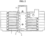
- FIG. 2 is a diagram showing a conventional battery module of a sensing structure using a printed circuit board.
- the conventional battery module of a sensing structure using the conventional printed circuit board has a sensing structure for voltage detection by pre-soldering the bus bar 2 to a soldering area S of the printed circuit board 4 and fixing the electrode lead 1 and the bus bar 2 using a structure or by welding.
- the conventional battery module of a sensing structure using the printed circuit board 4 uses the printed circuit board 4 to which the bus bar 2 is pre-soldered as described above, its problem is that a soldering process of the printed circuit board 4 and the bus bar 2 is added to the process of manufacturing the battery module, and an error in voltage detection occurs due to frequent faults occurring in the soldering process.
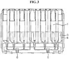
- FIG. 3 is a diagram showing a conventional battery module of a sensing structure using a clamping type bus bar.
- the conventional battery module has a sensing structure for voltage detection by welding the clamping type bus bar 5 to a welding area W of the electrode lead 1 to electrically connect the clamping type bus bar 5 and the electrode lead 1.
- the present disclosure is directed to providing a battery module with improved stability of electrical connection between an electrode lead and a sensing terminal and a battery pack and a vehicle comprising the same.
- a battery module includes a cell assembly including a plurality of battery cells stacked in up/down direction, each battery cell having an electrode lead in a shape of a plate that protrudes forward, the electrode lead being bent for surface contact in horizontal direction with an adjacent electrode lead, the electrode lead having a protruding part that protrudes forward from a front side end, and a sensing terminal module having a sensing terminal made of an electrical conductive material and a terminal seating hole in which the sensing terminal is seated and supported, the sensing terminal to which the protruding part is fit-coupled and which compresses around the protruding part.
- the adhesive member may be provided between adjacent protruding parts to adhere the protruding parts.
- the protruding part may have a left-right direction width that is equal to or less than a left-right direction width of the electrode lead.
- the sensing terminal may include a contact terminal part that comes into close contact with the protruding part, and a compression terminal part that extends from two sides of the contact terminal part and compresses around the protruding part.
- the contact terminal part may have a pressing protrusion therein to press a surface of the protruding part.
- a battery pack according to the present disclosure may include the above-described battery module.
- a plurality of battery cells 110 may be provided, and each battery cell 110 may be stacked on top of one another in up-down direction ( ⁇ Y axis direction).
- the protruding part 113 protruding in forward horizontal direction (+X axis direction) may be formed at an end (front end) of the front side of the electrode lead 111.
- the protruding part 113 may be formed with the same thickness as the other parts of the electrode lead 111. That is, the electrode lead 111 and the protruding part 113 may be formed with the same thickness in whole.
- the protruding part 113 may have a predetermined left-right direction width W2.
- the left-right direction width may be, in other words, a length that is measured on the basis of ⁇ Z axis.
- the protruding part 113 of the electrode lead 111 is directly connected to the sensing terminal to prevent instability of electrical connection that occurs in the process of mechanically connecting the receptacle or wire to the bus bar welded to the electrode lead.
- the sensing cover 200 may include a hook 210, a through-hole 230 and a module seating part 250.
- the sensing cover 200 may be coupled with the cell assembly 100 when the hook 210 formed at one end and the other end is engaged with a hook coupling part of a lead cartridge as described below.
- the sensing cover 200 may cover the side surface of the cell assembly 100 where the electrode lead is formed.
- the sensing cover 200 may have the module seating part 250 on which the sensing terminal module 300 is supported and seated in the opposite direction to the cell assembly 100. More specifically, the module seating part 250 may be formed in a shape corresponding to the contact surface with the sensing terminal module 300 when the sensing cover 200 and the sensing terminal module 300 are coupled.
- the sensing terminal module 300 will be described in detail with further reference to FIGS. 8 to 10 .
- FIG. 8 is an exploded perspective view of the sensing terminal module according to an embodiment of the present disclosure
- FIG. 9 is a cross-sectional view of the sensing terminal coupled with the protruding part according to an embodiment of the present disclosure
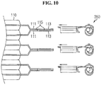
- FIG. 10 is a diagram showing a process in which the protruding part and the sensing terminal are coupled according to an embodiment of the present disclosure.
- the terminal seating hole 330 may apply the pressure to the sensing terminal 350 from the outer side when the sensing terminal 350 is inserted, supported and seated, to prevent the sensing terminal 350 from separating from it by an external force.
- a pressing protrusion 351a may be formed on the inside surface of the contact terminal part 351 to compress the protruding part 113, thereby improving coupling and fixing strength of the sensing terminal 350 and the protruding part 113.
- first compression terminal part 353a and the second compression terminal part 353b may be bent in downward direction from two sides of the contact terminal part. Additionally, through this bending configuration, the first compression terminal part 353a and the second compression terminal part 353b may have elasticity. Further, the first compression terminal part 353a and the second compression terminal part 353b place the protruding part 113 between the first compression terminal part 353a and the second compression terminal part 353b and the contact terminal part 351, to press up the lower part of the protruding part 113.
- the sensing terminal 350 may increase the coupling and fixing strength with the protruding part 113 through the compression terminal part 353 compressing around the protruding part 113, and particularly, may increase the operation efficiency with no need for separate equipment, for example, welding equipment.
- the sensing terminal 350 may be pressed and fixed by the pressing protrusion 351 formed in the contact terminal part 351 with which the protruding part 113 is in close contact. Additionally, the first compression terminal part 353a and the second compression terminal part 353b extending from the contact terminal part 351 compress below the protruding part 113 to fix the protruding part 113 to the sensing terminal 350 securely.
- the cell assembly 100 may further include a lead cartridge 130.
- the lead cartridge 130 is for mechanically preventing any electrical connection between the electrode leads that is not designed, and may individually receive each electrode lead electrically connected according to the design. To this end, the lead cartridge 130 may have a plurality of spaces inside to individually receive the electrically connected electrode leads.
- the lead cartridge 130 may prevent an unintentional contact between the electrode leads, and prevent damage of the electrode lead that may occur by an external force.
- a hook coupling part 131 to which the hook 210 of the sensing cover 200 as described below is coupled may be formed at one end and the other end of the lead cartridge 130.
- FIG 11 is a diagram showing a process in which the protruding part and the sensing terminal are coupled according to another embodiment of the present disclosure
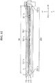
- FIG. 12 is a cross-sectional view of the sensing terminal coupled with the protruding part according to another embodiment.
- the protruding part 113' may protrude in horizontal direction (+X axis direction) from the end of the electrode lead 111, and a left-right direction width W3 of the protruding part (113 in FIG. 5 ) and the electrode lead 111 according to an embodiment may be equal to the left-right direction width W1 of the electrode lead 111.
- the joining member 115' may be also applied between the protrusions 113' corresponding to the left-right direction width W3 of the protrusion 113' in whole to mechanically join and electrically connect the protrusions 113'.
- the contact terminal part 351' may have a plurality of pressing protrusions 351'a corresponding to the left-right direction width W3 of the protruding part 113' on the inside surface to press the protruding part 113', thereby improving the coupling and fixing strength between the sensing terminal 350' and the protruding part 113'.
- the compression terminal part 353' may include a first compression terminal part 353'a and a second compression terminal part 353'b that extend from two side surfaces of the contact terminal part 351' and compress around each of the side surfaces of the protruding part 113'.
- the battery module according to the present disclosure may be applied to a vehicle such as an electric vehicle or a hybrid electric vehicle. That is, the vehicle according to the present disclosure may include the battery module according to the present disclosure.
Landscapes
- Chemical & Material Sciences (AREA)
- Chemical Kinetics & Catalysis (AREA)
- Electrochemistry (AREA)
- General Chemical & Material Sciences (AREA)
- Engineering & Computer Science (AREA)
- Manufacturing & Machinery (AREA)
- Aviation & Aerospace Engineering (AREA)
- Battery Mounting, Suspending (AREA)
- Connection Of Batteries Or Terminals (AREA)
- Secondary Cells (AREA)
Abstract
Description
- The present application claims priority to Korean Patent Application No.
10-2017-0045416 - The present disclosure relates to a battery module and a battery pack and a vehicle comprising the same, and more particularly, to a battery module with improved stability of electrical connection between an electrode lead and a sensing terminal and a battery pack and a vehicle comprising the same.
- Recently, with the dramatically increasing demand for portable electronic products such as laptop computers, video cameras, mobile phones, and the like, along with the extensive development of electric vehicles, accumulators for energy storage, robots, satellites, and the like, many studies are being made on high performance secondary batteries that can be repeatedly recharged.
- Currently, commercially available secondary batteries include nickel cadmium batteries, nickel hydrogen batteries, nickel zinc batteries, lithium secondary batteries and the like, and among them, lithium secondary batteries have little or no memory effect, and thus they are gaining more attention than nickel-based secondary batteries for their advantages of free charging/discharging, very low self-discharging, and high energy density.
- A lithium secondary battery usually uses a lithium-based oxide and a carbon material for a positive electrode active material and a negative electrode active material respectively. The lithium secondary battery includes an electrode assembly including a positive electrode plate and a negative electrode plate respectively coated with the positive electrode active material and the negative electrode active material with a separator interposed between, and a packaging or a battery case to hermetically receive the electrode assembly together with an electrolyte solution.
- In general, lithium secondary batteries may be classified into can-type secondary batteries in which an electrode assembly is embedded in a metal can and pouch-type secondary batteries in which an electrode assembly is embedded in a pouch of an aluminum laminate sheet according to the shape of the case.
- More recently, secondary batteries are being widely used in not only small devices such as portable electronic devices but also medium- and large-scale devices such as vehicles or energy storage systems. In particular, with the steady exhaustion of carbon energy and increasing interest in the environment, attention is paid to hybrid electric vehicles and electric vehicles all over the world including United States, Europe, Japan and the Republic of Korea. In such hybrid electric vehicles or electric vehicles, the most essential component is a battery pack that gives a driving power to an automobile motor. Because hybrid electric vehicles or electric vehicles are supplied with power for driving the vehicles through charging/discharging of battery packs, as compared to vehicles powered by an engine alone, they have higher fuel efficiency and can eliminate or lessen the emission of pollutants, and by this reason, the number of users is now increasing. The battery pack of hybrid electric vehicles or electric vehicles includes a plurality of secondary batteries, and the plurality of secondary batteries is connected in series and in parallel to improve the capacity and output.
- Meanwhile, in addition to the secondary batteries, the battery pack includes various battery pack protection devices such as Battery Management System (BMS). The protection devices may play many roles including managing the charge/discharge of the battery pack and ensuring safety. The protection devices may perform their functions in view of many factors, and a typical one of these factors is voltage of each secondary battery. For example, a specific protection device may prevent the overcharge or overdischarge of each secondary battery through voltage values across two ends of the corresponding secondary batteries, and perform a balancing function to reduce differences in state of charge between the secondary batteries.
- In executing a specific function of the protection device included in the battery pack, sensing the voltage of each secondary battery included in the battery pack is very important and essential, and thus configuration for detecting the voltage of the secondary batteries is applied to most of conventional battery packs.
-
FIG. 1 is a diagram showing a conventional battery module of a sensing structure in which an electrode lead and a receptacle are connected. - Referring to
FIG. 1 , the conventional battery module includes abus bar 2 joined with theelectrode lead 1 by welding and thereceptacle 3 connected to thebus bar 2 by mechanically applying the pressure to thebus bar 2, to form a sensing structure for voltage detection. - As described above, because the
receptacle 3 and thebus bar 2 are only coupled by the pressure applied from thereceptacle 3 of peg type without a separate fixing device, its problem is that connection is easily disconnected by the external pressure and vibration. -
FIG. 2 is a diagram showing a conventional battery module of a sensing structure using a printed circuit board. - Referring to
FIG. 2 , the conventional battery module of a sensing structure using the conventional printed circuit board has a sensing structure for voltage detection by pre-soldering thebus bar 2 to a soldering area S of the printed circuit board 4 and fixing theelectrode lead 1 and thebus bar 2 using a structure or by welding. - Because the conventional battery module of a sensing structure using the printed circuit board 4 uses the printed circuit board 4 to which the
bus bar 2 is pre-soldered as described above, its problem is that a soldering process of the printed circuit board 4 and thebus bar 2 is added to the process of manufacturing the battery module, and an error in voltage detection occurs due to frequent faults occurring in the soldering process. -
FIG. 3 is a diagram showing a conventional battery module of a sensing structure using a clamping type bus bar. - Referring to
FIG. 3 , the conventional battery module has a sensing structure for voltage detection by welding the clampingtype bus bar 5 to a welding area W of theelectrode lead 1 to electrically connect the clampingtype bus bar 5 and theelectrode lead 1. - Subsequently, a plurality of
wires 6 extending from the end of the clampingtype bus bar 5 is arranged outside of the battery module, to manufacture the battery module. - The problem of the conventional battery module of a sensing structure using the clamping
type bus bar 5 is that a process of welding the clampingtype bus bar 5 and theelectrode lead 1 and a process of arranging the plurality ofwires 6 outside in the course of assembling the battery module are additionally needed, and the energy density of the battery module reduces due to the plurality ofwires 6. - The present disclosure is directed to providing a battery module with improved stability of electrical connection between an electrode lead and a sensing terminal and a battery pack and a vehicle comprising the same.
- The present disclosure is further directed to providing a battery module in which a sensing terminal for sensing the voltage of a battery cell and an electrode lead are only coupled by an assembling process through pressing and a battery pack and a vehicle comprising the same.
- The objects of the present disclosure are not limited to the above-mentioned objects and these and other objects and advantages of the present disclosure can be understood by the following description and will be apparent from the embodiments of the present disclosure. Further, it will be readily understood that the objects and advantages of the present disclosure are realized by the means set forth in the appended claims and combinations thereof.
- To achieve the above-described object, a battery module according to the present disclosure includes a cell assembly including a plurality of battery cells stacked in up/down direction, each battery cell having an electrode lead in a shape of a plate that protrudes forward, the electrode lead being bent for surface contact in horizontal direction with an adjacent electrode lead, the electrode lead having a protruding part that protrudes forward from a front side end, and a sensing terminal module having a sensing terminal made of an electrical conductive material and a terminal seating hole in which the sensing terminal is seated and supported, the sensing terminal to which the protruding part is fit-coupled and which compresses around the protruding part.
- Preferably, the cell assembly may include an adhesive member provided between the electrode leads in surface contact to adhere the electrode leads.
- Preferably, the adhesive member may be made of an electrical conductive material.
- Preferably, the adhesive member may be provided between adjacent protruding parts to adhere the protruding parts.
- Preferably, the protruding part may have a left-right direction width that is equal to or less than a left-right direction width of the electrode lead.
- Preferably, the sensing terminal may include a contact terminal part that comes into close contact with the protruding part, and a compression terminal part that extends from two sides of the contact terminal part and compresses around the protruding part.
- Preferably, the contact terminal part may have a pressing protrusion therein to press a surface of the protruding part.
- Preferably, the battery module may further include a sensing cover coupled to a side surface of the cell assembly where the electrode lead is disposed to cover the electrode lead.
- Preferably, the sensing cover may have a through-hole that runs in a direction in which the protruding part protrudes, and into which the protruding part is inserted.
- Preferably, the sensing cover may have a module seating part where the sensing terminal module is seated and supported on an opposite side surface to the cell assembly.
- A battery pack according to the present disclosure may include the above-described battery module.
- A vehicle according to the present disclosure may include the above-described battery module.
- According to the present disclosure, it is possible to improve stability of electrical connection of the electrode lead and the sensing terminal.
- Additionally, the present disclosure only connects the electrode lead and the sensing terminal by a process through pressing without a welding process and a soldering process, thereby simplifying the process of manufacturing a battery module and reducing an error ratio.
-
-
FIG. 1 is a diagram showing a conventional battery module of a sensing structure in which an electrode lead and a receptacle are connected. -
FIG. 2 is a diagram showing a conventional battery module of a sensing structure using a printed circuit board. -
FIG. 3 is a diagram showing a conventional battery module of a sensing structure using a clamping type bus bar. -
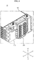
FIG. 4 is a partial perspective view of a battery module according to an embodiment of the present disclosure. -
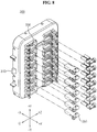
FIG. 5 is a partial exploded perspective view of a battery module according to an embodiment of the present disclosure. -
FIG. 6 is a schematic perspective view of a battery cell according to an embodiment of the present disclosure. -
FIG. 7 is an enlarged view of section A ofFIG. 6 . -
FIG. 8 is an exploded perspective view of a sensing terminal module according to an embodiment of the present disclosure. -
FIG. 9 is a cross-sectional view of a sensing terminal coupled with a protruding part according to an embodiment of the present disclosure. -
FIG. 10 is a diagram showing a process in which a protruding part and a sensing terminal are coupled according to an embodiment of the present disclosure. -
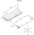
FIG. 11 is a diagram showing a process in which a protruding part and a sensing terminal are coupled according to another embodiment of the present disclosure. -
FIG. 12 is a front view of a sensing terminal according to another embodiment. - The above-described objects, features and advantages will be described in detail with reference to the accompanying drawings, and accordingly, those having ordinary skill in the technical field pertaining to the present disclosure will easily practice the technical aspects of the present disclosure. In describing the present disclosure, when it is deemed that a detailed description of relevant known technology unnecessarily renders the key subject matter of the present disclosure ambiguous, the detailed description is omitted herein. Hereinafter, preferred embodiments of the present disclosure will be described in detail with reference to the accompanying drawings. In the drawings, like reference numerals are used to indicate like or similar elements.
-
FIG. 4 is a partial perspective view of a battery module according to an embodiment of the present disclosure, andFIG. 5 is a partial exploded perspective view of the battery module according to an embodiment of the present disclosure. - Referring to
FIGS. 4 and5 , thebattery module 10 according to an embodiment of the present disclosure may include acell assembly 100, asensing cover 200 and asensing terminal module 300. - The
cell assembly 100 may include abattery cell 110. - A plurality of
battery cells 110 may be provided, and eachbattery cell 110 may be stacked on top of one another in up-down direction (±Y axis direction). - The
battery cell 110 is not limited to a particular type, and various types of secondary batteries may be used in thecell assembly 100 of thebattery module 10 according to the present disclosure. For example, thebattery cell 110 may include lithium ion batteries, lithium polymer batteries, nickel cadmium batteries, nickel hydrogen batteries and nickel zinc batteries. Particularly, thebattery cell 110 may be a lithium secondary battery. - Meanwhile, the
battery cell 110 may be classified into pouch type, cylindrical and prismatic according to the type of case. Particularly, thebattery cell 110 of thebattery module 10 according to the present disclosure may be a pouch-type secondary battery. - When the
battery cell 110 is a pouch-type secondary battery, as shown inFIGS. 4 and5 , eachbattery cell 110 is arranged with wide surfaces positioned on top of one another, and the wide surfaces between eachbattery cell 100 face each other. Additionally, in this case, eachbattery cell 110 may have an electrode lead that protrudes in horizontal direction (+X axis direction). - The electrode lead may include a positive electrode lead and a negative electrode lead, and the positive electrode lead may be connected to a positive electrode plate of an electrode assembly and the negative electrode lead may be connected to a negative electrode plate of the electrode assembly.
- Hereinafter, the structure of the electrode lead will be described in detail with reference to
FIGS. 6 and7 . -
FIG. 6 is a schematic perspective view of the battery cell according to an embodiment of the present disclosure, andFIG. 7 is an enlarged view of section A ofFIG. 6 . - Referring to
FIGS. 6 and7 , theelectrode lead 111 may be formed in a plate shape and protrude in horizontal direction (+X axis direction). Particularly, theelectrode lead 111 provided in thebattery cell 110 may be bent toward an electrode lead of another battery cell stacked above or below. For example, in the configuration ofFIGS. 6 and7 , among twoelectrode leads battery cells 110 stacked vertically, theelectrode lead 111a disposed in lower position may protrude and extend in horizontal direction (+X axis direction, forward), be bent in upward direction (+Y axis direction, +X axis direction), and extend in horizontal direction (+X axis direction) again. Additionally, among twoelectrode leads electrode lead 111b disposed on upper position may protrude and extend in horizontal direction (+X axis direction), be bent in downward direction (-Y axis direction, +X axis direction), and extend in horizontal direction (+X axis direction) again. - In this instance, regions (A' region of
FIG. 7 ) where the two adjacent electrode leads 111a, 111b extend in horizontal direction (+X axis direction) after bent may have surface contact with each other. Through this, the plurality ofbattery cells 110 may be electrically connected to form the cell assembly (100 inFIG. 4 ). - Meanwhile, a joining
member 115 may be provided between the A' regions of the two adjacent electrode leads 111a, 111b to join the electrode leads 111a, 111b. Here, the joining member 150 may be made of an electrical conductive material to electrically connect the electrode leads 111a, 111b. - Through this, the joining member 150 maintains a secure electrical connection between the electrode leads 111a, 111b, thereby preventing a short circuit between the electrode leads 111a, 111b that may occur due to an external impact or vibration.
- Meanwhile, the protruding
part 113 protruding in forward horizontal direction (+X axis direction) may be formed at an end (front end) of the front side of theelectrode lead 111. The protrudingpart 113 may be formed with the same thickness as the other parts of theelectrode lead 111. That is, theelectrode lead 111 and theprotruding part 113 may be formed with the same thickness in whole. Additionally, the protrudingpart 113 may have a predetermined left-right direction width W2. Here, the left-right direction width may be, in other words, a length that is measured on the basis of ±Z axis. - More specifically, the left-right direction width W2 of the
protruding part 113 may be equal to or less than the left-right direction width W1 of theelectrode lead 111. Additionally, the protrudingpart 113 may be integrally formed with theelectrode lead 111. - Meanwhile, the protruding
part 113 may be formed in both the two electrode leads 111 that are stacked in up-down direction (±Y axis direction) and connected to each other. In this case, a joiningmember 115 may be also provided between the two protrudingparts 113 disposed in up-down direction (±Y axis direction). Additionally, the joiningmember 115 may join the two adjacent stacked protrudingparts 113. Accordingly, not only the electrode leads 111a, 111b but also the protrudingparts 113 may be electrically connected through the joiningmember 115. According to the embodiment of this configuration, a portion of the front end of the joiningmember 115 may protrude forward corresponding to the shape of theelectrode lead part 113 at the front end. - The protruding
part 113 may be fit-coupled to a sensing terminal. Additionally, the sensing terminal may be provided in the sensing terminal module. - Through this, the protruding
part 113 of theelectrode lead 111 according to the present disclosure is directly connected to the sensing terminal to prevent instability of electrical connection that occurs in the process of mechanically connecting the receptacle or wire to the bus bar welded to the electrode lead. - The above-described connection configuration between the
protruding part 113 and the sensing terminal will be described in detail below. - Returning to
FIGS. 4 and5 , another configuration of thebattery module 10 will be described. - The
sensing cover 200 may include ahook 210, a through-hole 230 and amodule seating part 250. - The
sensing cover 200 may be coupled with thecell assembly 100 when thehook 210 formed at one end and the other end is engaged with a hook coupling part of a lead cartridge as described below. Here, thesensing cover 200 may cover the side surface of thecell assembly 100 where the electrode lead is formed. - That is, the
sensing cover 200 may be coupled with thecell assembly 100 to cover the side surface of thecell assembly 100 in order not to expose the electrode lead and thelead cartridge 130 to the outside. - The through-
hole 230 may be formed at a location corresponding to the location of theprotruding part 113 when thesensing cover 200 and thecell assembly 100 are coupled. - The protruding
part 113 passes through the through-hole 230 in a direction (+X axis direction) in which theprotruding part 113 protrudes. Through this, when thesensing cover 200 is coupled to thecell assembly 100, the protrudingpart 113 may pass through the through-hole 230 and protrude from thesensing cover 200. - Through this, the protruding
part 113 may protrude to reach the sensing terminal and be coupled with the sensing terminal. - To this end, the depth of the through-
hole 230 may be smaller than the length of theprotruding part 113. - Additionally, the number of through-
holes 230 may correspond to the number of protrudingparts 113. For example, as shown inFIG. 5 , in onecell assembly 100, a total of 14 protrudingparts 113 may be provided, two in left-right direction (±X axis direction) and seven rows in up-down direction (±Y axis direction). In this case, a total of 14 through-holes 230 may be provided corresponding to the number and arrangement of protrudingparts 113, each two in seven rows. - Meanwhile, the
sensing cover 200 may have themodule seating part 250 on which thesensing terminal module 300 is supported and seated in the opposite direction to thecell assembly 100. More specifically, themodule seating part 250 may be formed in a shape corresponding to the contact surface with thesensing terminal module 300 when thesensing cover 200 and thesensing terminal module 300 are coupled. - Through this, the
sensing terminal module 300 may be supported so that it does not separate from thesensing cover 200. - To this end, the
guide groove 251 may be formed on the outer periphery of themodule seating part 250 to guide the movement of thesensing terminal module 300 when thesensing terminal module 300 enters. - More specifically, a
protrusion 310 may protrude on the outer periphery of thesensing terminal module 300 corresponding to the location of theguide groove 251, and when thesensing terminal module 300 enters themodule seating part 250, theprotrusion 310 may be inserted into aguide groove 251. - Subsequently, the
guide groove 251 may guide the movement of the insertedprotrusion 310, and support theprotrusion 310 so that thesensing terminal module 300 is smoothly seated on themodule seating part 250. - Through this, the
sensing terminal module 300 may be only coupled in simple manner by a pressing process after moving to thesensing cover 200 coupled to thecell assembly 100 without a separate welding process. - Subsequently, the
sensing terminal module 300 will be described in detail with further reference toFIGS. 8 to 10 . -
FIG. 8 is an exploded perspective view of the sensing terminal module according to an embodiment of the present disclosure,FIG. 9 is a cross-sectional view of the sensing terminal coupled with the protruding part according to an embodiment of the present disclosure, andFIG. 10 is a diagram showing a process in which the protruding part and the sensing terminal are coupled according to an embodiment of the present disclosure. - In addition to the
protruding part 310, thesensing terminal module 300 may further include aterminal seating hole 330 and asensing terminal 350. - The
protrusion 310 protrudes from the outer periphery of thesensing terminal module 300 as described above, and when thesensing terminal module 300 is coupled to themodule seating part 250, theprotrusion 310 may be inserted into theguide groove 251 of themodule seating part 250 and move along theguide groove 251. - Additionally, the
protrusion 310 may be supported from theguide groove 251 after entering theguide groove 251 to the end, and may fix thesensing terminal module 300 in themodule seating part 250. - Meanwhile, the
sensing terminal module 300 may have theterminal seating hole 330 where thesensing terminal 350 is supported and seated in the opposite direction to thesensing cover 200. More specifically, theterminal seating hole 330 may be in the shape of a hole that corresponds to the shape of thesensing terminal 350 and runs in horizontal direction (±X axis direction). - The
terminal seating hole 330 may apply the pressure to thesensing terminal 350 from the outer side when thesensing terminal 350 is inserted, supported and seated, to prevent thesensing terminal 350 from separating from it by an external force. - Through this, when the
protruding part 113 formed at the end of theelectrode lead 111 is inserted into thesensing terminal 350, the pressure applied from the protrudingpart 113 may prevent thesensing terminal 350 from separating from theterminal seating hole 330. - The
sensing terminal 350 may be electrically connected to theelectrode lead 111 by the fit-coupling of theprotruding part 113 as shown inFIG. 10 . - The
sensing terminal 350 is a component that is in direct contact with theprotruding part 113 integrally formed with theelectrode lead 111 to sense the voltage of thebattery cell 110, and may be made of an electrical conductive material of metal such as aluminum or copper. - Meanwhile, the
sensing terminal 350 may include acontact terminal part 351 that is close contact with theprotruding part 113, and acompression terminal part 353 that extends from two sides of thecontact terminal part 351 and compresses around the protrudingpart 113. - The
contact terminal part 351 has a flat plate shape, and theprotruding part 113 may contact and be coupled below thecontact terminal part 351 of flat plate. - In this instance, a
pressing protrusion 351a may be formed on the inside surface of thecontact terminal part 351 to compress theprotruding part 113, thereby improving coupling and fixing strength of thesensing terminal 350 and theprotruding part 113. - Meanwhile, as shown in
FIG. 9 , thecompression terminal part 353 may include a firstcompression terminal part 353a and a secondcompression terminal part 353b that compress around each of two side surfaces of theprotruding part 113. That is, the firstcompression terminal part 353a and the secondcompression terminal part 353b may extend from two side surfaces of thecontact terminal part 351 and compress around each of the side surfaces of theprotruding part 113, thereby compressing and fixing theprotruding part 113 more securely. - Particularly, the first
compression terminal part 353a and the secondcompression terminal part 353b may be bent in downward direction from two sides of the contact terminal part. Additionally, through this bending configuration, the firstcompression terminal part 353a and the secondcompression terminal part 353b may have elasticity. Further, the firstcompression terminal part 353a and the secondcompression terminal part 353b place the protrudingpart 113 between the firstcompression terminal part 353a and the secondcompression terminal part 353b and thecontact terminal part 351, to press up the lower part of theprotruding part 113. - Through this, the
sensing terminal 350 may increase the coupling and fixing strength with theprotruding part 113 through thecompression terminal part 353 compressing around the protrudingpart 113, and particularly, may increase the operation efficiency with no need for separate equipment, for example, welding equipment. - That is, the
sensing terminal 350 according to the present disclosure may be pressed and fixed by thepressing protrusion 351 formed in thecontact terminal part 351 with which theprotruding part 113 is in close contact. Additionally, the firstcompression terminal part 353a and the secondcompression terminal part 353b extending from thecontact terminal part 351 compress below the protrudingpart 113 to fix theprotruding part 113 to thesensing terminal 350 securely. - Returning to
FIGS. 4 and5 , another configuration of the cell assembly will be described. - Referring to
FIGS. 4 and5 , thecell assembly 100 may further include alead cartridge 130. - The
lead cartridge 130 is for mechanically preventing any electrical connection between the electrode leads that is not designed, and may individually receive each electrode lead electrically connected according to the design. To this end, thelead cartridge 130 may have a plurality of spaces inside to individually receive the electrically connected electrode leads. - Additionally, the
lead cartridge 130 may run in horizontal direction (±X axis direction) so that the electrode lead is inserted and the above-describedprotruding part 113 protrudes outwards. Accordingly, the protrudingpart 113 may be inserted into the inner surface and protrude out of the outer surface while thelead cartridge 130 is coupled with thebattery cell 110, and two electrode leads in surface contact may be received in the internal space of thelead cartridge 130. - Through this, the
lead cartridge 130 may prevent an unintentional contact between the electrode leads, and prevent damage of the electrode lead that may occur by an external force. - Meanwhile, a
hook coupling part 131 to which thehook 210 of thesensing cover 200 as described below is coupled may be formed at one end and the other end of thelead cartridge 130. - In the coupling of the
cell assembly 100 and thesensing cover 200, thehook coupling part 131 holds the end of thehook 210 in the opposite direction (+X axis direction) to the coupling direction (-X axis direction), to fix thehook 210 and couple thesensing cover 200 connected to thehook 210 with thecell assembly 100. - Through this, the
cell assembly 100 and thesensing cover 200 may be only coupled in simple manner by a process of pressing thesensing cover 200 in the coupling direction (-X axis direction). - Hereinafter, the coupling configuration of the protruding part and the sensing terminal according to another embodiment of the present disclosure will be described.
-
FIG 11 is a diagram showing a process in which the protruding part and the sensing terminal are coupled according to another embodiment of the present disclosure, andFIG. 12 is a cross-sectional view of the sensing terminal coupled with the protruding part according to another embodiment. - Referring to
FIGS. 11 and12 , the protrudingpart 113' and the sensing terminal 350' according to another embodiment of the present disclosure have the same or similar role and coupling structure with other components to the protruding part (113 inFIG. 5 ) and the sensing terminal (350 inFIG. 5 ) according to an embodiment of the present disclosure as described previously, and a description will be provided based on a difference with a repeated description being omitted herein. - The protruding
part 113' according to another embodiment of the present disclosure may protrude in horizontal direction (+X axis direction) from the end of theelectrode lead 111, and a left-right direction width W3 of the protruding part (113 inFIG. 5 ) and theelectrode lead 111 according to an embodiment may be equal to the left-right direction width W1 of theelectrode lead 111. - That is, the protruding
part 113' according to another embodiment may protrude in horizontal direction (+ axis direction) while maintaining the same width from the end of theelectrode lead 111. Accordingly, the protrudingpart 113' according to another embodiment can contact the sensing terminal 350' as opposed to the protruding part (113 inFIG. 5 ) according to an embodiment, thereby increasing the area and improving the coupling strength with the sensing terminal 350' and stability of electrical connection. - Meanwhile, the joining member 115' may be also applied between the
protrusions 113' corresponding to the left-right direction width W3 of theprotrusion 113' in whole to mechanically join and electrically connect theprotrusions 113'. - Meanwhile, the sensing terminal 350' according to another embodiment may include a contact terminal part 351' and a compression terminal part 353' with a left-right direction width W4 corresponding to the left-right direction width W3 of the
protrusion 113'. - As described above, the protruding
part 113' of theelectrode lead 111 fit-coupled to the sensing terminal 350' may be coupled in surface contact with the contact terminal part 351'. In this instance, the left-right direction width W4 of the contact terminal part 351' may be equal to or longer than the left-right direction width W3 of theprotruding part 113' by a predetermined length. - According to this configuration of the present disclosure, the protruding
part 113' according to another embodiment has a longer width and a wider area than the protruding part (113 inFIG. 5 ) according to an embodiment, and thus may be seated and supported on the sensing terminal 350' more stably. Accordingly, in this case, mechanical support and electrical connectivity between theelectrode lead 111 and the sensing terminal 350' may be maintained more stably. - Meanwhile, a plurality of protruding parts may be provided according to still another embodiment of the present disclosure. More specifically, the protruding parts according to still another embodiment of the present disclosure may be formed in the shape of a plurality of plates that protrudes in horizontal direction (+X axis direction) from the end of the electrode lead, spaced apart from each other. For example, in the case of three protruding parts according to still another embodiment of the present disclosure, the protruding parts may include a first protruding part, a second protruding part and a third protruding part that protrude from one end, the other end and the center of the electrode lead respectively, spaced apart from each other.
- Through this, the protruding part according to still another embodiment of the present disclosure may be formed at a point to which a coupling force from the sensing terminal 350' is applied, thereby improving the coupling and fixing strength with the sensing terminal 350'.
- Meanwhile, the contact terminal part 351' according to the embodiment of
FIGS. 11 and12 may have a plurality of pressing protrusions 351'a corresponding to the left-right direction width W3 of theprotruding part 113' on the inside surface to press the protrudingpart 113', thereby improving the coupling and fixing strength between the sensing terminal 350' and theprotruding part 113'. - The sensing terminal 350' according to another embodiment of
FIGS. 11 and12 may further include a compression terminal part 353' that extends from two sides of the contact terminal part 351' and compresses around the protrudingpart 113'. - The compression terminal part 353' may include a first compression terminal part 353'a and a second compression terminal part 353'b that extend from two side surfaces of the contact terminal part 351' and compress around each of the side surfaces of the
protruding part 113'. - The first compression terminal part 353'a and the second compression terminal part 353'b according to another embodiment may be formed such that the end compressing the
protruding part 113' extends corresponding to the left-right direction width W3 of theprotruding part 113'. - That is, to securely compress the long and wide
protruding part 113', each end part of the first compression terminal part 353'a and the second compression terminal part 353'b according to this embodiment may extend longitudinally to the center of theprotruding part 113' to compress theprotruding part 113'. In this case, the first compression terminal part 353'a and the second compression terminal part 353'b may have a bending part in a curved shape that is bent from two sides of the contact terminal part 351', and a flat part that extends flat in a direction toward the center of theprotruding part 113', i.e., inward direction from each bending part. - Through this, the sensing terminal 351' and the
protruding part 113' may be coupled in surface contact over the wide area and electrically connected to each other, thereby improving stability of mechanical coupling and stability of electrical connection. - Meanwhile, the battery pack according to the present disclosure includes at least one battery module described above. In this instance, in addition to the battery module, the battery pack may further include a case to receive the battery module and various types of devices to control the charge/discharge of the battery module, for example, a Battery Management System (BMS), a current sensor, a fuse, and the like. Particularly, the battery pack according to an embodiment of the present disclosure may have an electrical connection of the sensing terminal seated in the sensing terminal module of the battery module and the connection terminal of the BMS.
- The battery module according to the present disclosure may be applied to a vehicle such as an electric vehicle or a hybrid electric vehicle. That is, the vehicle according to the present disclosure may include the battery module according to the present disclosure.
- The above-described present disclosure is not limited to the above-described embodiments and the accompanying drawings, and many substitutions, modifications and changes may be made thereto by those having ordinary skill in the technical field pertaining to the present disclosure without departing from the technical aspects of the present disclosure.
Claims (11)
- A battery module comprising:a cell assembly including a plurality of battery cells stacked in up/down direction, each battery cell having an electrode lead in a shape of a plate that protrudes forward, the electrode lead being bent for surface contact in horizontal direction with an adjacent electrode lead, the electrode lead having a protruding part that protrudes forward from a front side end; anda sensing terminal module having a sensing terminal made of an electrical conductive material and a terminal seating hole in which the sensing terminal is seated and supported, the sensing terminal to which the protruding part is fit-coupled and which compresses around the protruding part.
- The battery module according to claim 1, wherein the cell assembly includes an adhesive member provided between the electrode leads in surface contact to adhere the electrode leads, and
the adhesive member is made of an electrical conductive material. - The battery module according to claim 2, wherein the adhesive member is provided between adjacent protruding parts to adhere the protruding parts.
- The battery module according to claim 1, wherein the protruding part has a left-right direction width that is equal to or less than a left-right direction width of the electrode lead.
- The battery module according to claim 1, wherein the sensing terminal includes a contact terminal part that comes into close contact with the protruding part, and a compression terminal part that extends from two sides of the contact terminal part and compresses around the protruding part.
- The battery module according to claim 5, wherein the contact terminal part has a pressing protrusion therein to press a surface of the protruding part.
- The battery module according to claim 1, further comprising:
a sensing cover coupled to a side surface of the cell assembly where the electrode lead is disposed to cover the electrode lead. - The battery module according to claim 7, wherein the sensing cover has a through-hole that runs in a direction in which the protruding part protrudes, and into which the protruding part is inserted.
- The battery module according to claim 7, wherein the sensing cover has a module seating part where the sensing terminal module is seated and supported on an opposite side surface to the cell assembly.
- A battery pack comprising the battery module according to any of claims 1 to 9.
- A vehicle comprising the battery module according to any of claims 1 to 9.
Applications Claiming Priority (2)
| Application Number | Priority Date | Filing Date | Title |
|---|---|---|---|
| KR1020170045416A KR102140311B1 (en) | 2017-04-07 | 2017-04-07 | Battery module, battery pack including the same, and vehicle including the same |
| PCT/KR2018/003922 WO2018186659A1 (en) | 2017-04-07 | 2018-04-03 | Battery module, and battery pack and vehicle comprising same |
Publications (2)
| Publication Number | Publication Date |
|---|---|
| EP3550660A1 true EP3550660A1 (en) | 2019-10-09 |
| EP3550660A4 EP3550660A4 (en) | 2020-04-22 |
Family
ID=63712188
Family Applications (1)
| Application Number | Title | Priority Date | Filing Date |
|---|---|---|---|
| EP18781665.7A Pending EP3550660A4 (en) | 2017-04-07 | 2018-04-03 | BATTERY MODULE, BATTERY PACK AND VEHICLE COMPRISING THE SAME |
Country Status (6)
| Country | Link |
|---|---|
| US (1) | US11251505B2 (en) |
| EP (1) | EP3550660A4 (en) |
| JP (1) | JP6793841B2 (en) |
| KR (1) | KR102140311B1 (en) |
| CN (1) | CN110114932B (en) |
| WO (1) | WO2018186659A1 (en) |
Cited By (1)
| Publication number | Priority date | Publication date | Assignee | Title |
|---|---|---|---|---|
| EP3989346A4 (en) * | 2020-06-11 | 2022-12-21 | LG Energy Solution, Ltd. | ASSEMBLY TYPE BATTERY PACK FOR ESS |
Families Citing this family (12)
| Publication number | Priority date | Publication date | Assignee | Title |
|---|---|---|---|---|
| US12176505B2 (en) * | 2017-12-26 | 2024-12-24 | Sk On Co., Ltd. | Battery module and manufacturing method thereof |
| CN111106301B (en) * | 2019-04-02 | 2021-02-26 | 宁德时代新能源科技股份有限公司 | Secondary battery and battery module |
| CN114375525B (en) * | 2019-12-20 | 2024-06-21 | 株式会社Lg新能源 | Sub-battery pack and battery pack including the sub-battery pack |
| KR102840910B1 (en) * | 2020-02-17 | 2025-07-30 | 주식회사 엘지에너지솔루션 | No-welding Inserting Type Battery Pack and Method for manufacturing the same |
| KR102847235B1 (en) * | 2020-06-17 | 2025-08-14 | 주식회사 엘지에너지솔루션 | Battery module with non-welded structure as a connection structure between a busbar and a voltage sensing member |
| KR102991784B1 (en) * | 2020-07-02 | 2026-07-15 | 주식회사 엘지에너지솔루션 | Battery module and battery pack including the same and manufacturing method of the same |
| KR102976055B1 (en) * | 2020-10-05 | 2026-06-10 | 현대자동차주식회사 | Battery module |
| CN214706124U (en) * | 2021-03-30 | 2021-11-12 | 比亚迪股份有限公司 | Battery packs and electric vehicles |
| CN214706024U (en) * | 2021-03-30 | 2021-11-12 | 比亚迪股份有限公司 | Sampling structures, battery packs and electric vehicles |
| KR102910768B1 (en) | 2021-07-22 | 2026-01-12 | 에스케이온 주식회사 | Battery module and Battery pack having the same |
| KR102637525B1 (en) | 2021-10-26 | 2024-02-19 | 주식회사 엘지에너지솔루션 | Battery moule and battery pack including the same |
| KR102656950B1 (en) * | 2021-11-12 | 2024-04-16 | 주식회사 엘지에너지솔루션 | Battery moule and battery pack including the same |
Family Cites Families (29)
| Publication number | Priority date | Publication date | Assignee | Title |
|---|---|---|---|---|
| JP4047919B2 (en) * | 2002-07-19 | 2008-02-13 | 日本特殊陶業株式会社 | Sensor, sensor manufacturing method, assembly of separator and biasing member |
| JP3789439B2 (en) * | 2003-03-03 | 2006-06-21 | Necラミリオンエナジー株式会社 | Film exterior laminated battery pack |
| JP2006196428A (en) * | 2004-05-31 | 2006-07-27 | Nissan Motor Co Ltd | Battery pack and manufacturing method thereof |
| KR100646529B1 (en) * | 2005-03-24 | 2006-11-23 | 삼성에스디아이 주식회사 | Lithium secondary battery |
| KR100803435B1 (en) * | 2006-02-10 | 2008-02-13 | 엘에스전선 주식회사 | Ptc element that can be installed in battery cap and secondary battery using same |
| EP1994582B1 (en) * | 2006-03-06 | 2019-12-04 | LG Chem, Ltd. | Middle or large-sized battery module |
| JP5176312B2 (en) | 2006-12-07 | 2013-04-03 | 日産自動車株式会社 | Battery pack and manufacturing method thereof |
| CN101315990B (en) | 2007-05-29 | 2010-06-09 | 上海比亚迪有限公司 | a battery pack |
| KR20100035944A (en) | 2008-09-29 | 2010-04-07 | 현대자동차주식회사 | Voltage sensing apparatus for battery of hev |
| KR101152635B1 (en) * | 2010-04-08 | 2012-06-04 | 주식회사 엘지화학 | Voltage Sensing Assembly for Battery Module and Battery Module Employed with the Same |
| JP2012138271A (en) * | 2010-12-27 | 2012-07-19 | Sanyo Electric Co Ltd | Battery pack |
| KR101186628B1 (en) | 2011-05-04 | 2012-09-27 | 주식회사 경신 | Voltage sensing module for hybrid vehicle |
| JP2013105700A (en) * | 2011-11-16 | 2013-05-30 | Yazaki Corp | Power supply device |
| JP2013105699A (en) | 2011-11-16 | 2013-05-30 | Yazaki Corp | Power supply device |
| KR101539236B1 (en) * | 2012-10-18 | 2015-07-24 | 주식회사 엘지화학 | Battery Cell Having Electrode Lead of Improved Resistance Pressure and Stability |
| KR101456936B1 (en) * | 2012-12-27 | 2014-10-31 | 에이치엘그린파워 주식회사 | Voltage sensing circuit for vehicle battery and Cell Module Assembly including the same |
| KR101717199B1 (en) | 2013-08-29 | 2017-03-16 | 주식회사 엘지화학 | Battery Cell Having Connecting Protrusion for Voltage Sensing and Battery Module Comprising the Same |
| KR101707976B1 (en) * | 2013-10-29 | 2017-02-17 | 주식회사 엘지화학 | Battery module equipped with sensing modules having an improved coupling structure |
| KR102046125B1 (en) * | 2013-11-13 | 2019-11-18 | 에스케이이노베이션 주식회사 | Detachable voltage sensing module for Secondary-battery and Battery device having the same |
| KR20150062777A (en) * | 2013-11-29 | 2015-06-08 | 주식회사 엘지화학 | Battery module and battery pack including the same |
| KR101743696B1 (en) | 2013-11-29 | 2017-06-05 | 주식회사 엘지화학 | Battery module and battery pack including the same |
| KR102320036B1 (en) * | 2014-04-03 | 2021-11-01 | 타이코에이엠피 주식회사 | A battery module assembly |
| KR20150115250A (en) | 2014-04-03 | 2015-10-14 | 주식회사 엘지화학 | Battery pack having inner tention-bar |
| JP6455705B2 (en) | 2014-10-21 | 2019-01-23 | 株式会社オートネットワーク技術研究所 | Power storage module |
| JP6414478B2 (en) | 2015-02-03 | 2018-10-31 | 株式会社デンソー | Assembled battery and method of manufacturing the assembled battery |
| US20170025661A1 (en) * | 2015-07-23 | 2017-01-26 | Ford Global Technologies, Llc | Sensor lead securing assembly and method |
| KR101752302B1 (en) | 2015-10-16 | 2017-07-03 | 지엠텍(주) | Method of recovery prussian blue and apparatus thereof |
| KR102034206B1 (en) * | 2016-07-26 | 2019-10-18 | 주식회사 엘지화학 | Battery module and battery pack including the same |
| CN205882054U (en) | 2016-08-01 | 2017-01-11 | 宁德时代新能源科技股份有限公司 | Secondary battery |
-
2017
- 2017-04-07 KR KR1020170045416A patent/KR102140311B1/en active Active
-
2018
- 2018-04-03 US US16/347,316 patent/US11251505B2/en active Active
- 2018-04-03 EP EP18781665.7A patent/EP3550660A4/en active Pending
- 2018-04-03 CN CN201880005432.8A patent/CN110114932B/en active Active
- 2018-04-03 WO PCT/KR2018/003922 patent/WO2018186659A1/en not_active Ceased
- 2018-04-03 JP JP2019538200A patent/JP6793841B2/en active Active
Cited By (2)
| Publication number | Priority date | Publication date | Assignee | Title |
|---|---|---|---|---|
| EP3989346A4 (en) * | 2020-06-11 | 2022-12-21 | LG Energy Solution, Ltd. | ASSEMBLY TYPE BATTERY PACK FOR ESS |
| US12170385B2 (en) | 2020-06-11 | 2024-12-17 | Lg Energy Solution, Ltd. | Modular battery pack for energy storage system |
Also Published As
| Publication number | Publication date |
|---|---|
| KR102140311B1 (en) | 2020-07-31 |
| JP2020514983A (en) | 2020-05-21 |
| KR20180113814A (en) | 2018-10-17 |
| CN110114932B (en) | 2022-05-10 |
| JP6793841B2 (en) | 2020-12-02 |
| EP3550660A4 (en) | 2020-04-22 |
| CN110114932A (en) | 2019-08-09 |
| WO2018186659A1 (en) | 2018-10-11 |
| US11251505B2 (en) | 2022-02-15 |
| US20200058918A1 (en) | 2020-02-20 |
Similar Documents
| Publication | Publication Date | Title |
|---|---|---|
| US11251505B2 (en) | Battery module, and battery pack and vehicle comprising same | |
| EP3076456B1 (en) | Battery module and battery pack comprising same | |
| JP7045591B2 (en) | Battery module with busbar assembly | |
| EP3671902B1 (en) | Battery module having bus bar assembly | |
| EP2919296B1 (en) | Battery module comprising bus bar assembly, and battery pack comprising same | |
| EP3240062B1 (en) | Battery module and battery pack comprising same | |
| US12431591B2 (en) | Battery module having busbar, battery pack and vehicle | |
| EP2562842B1 (en) | Battery module | |
| KR102034206B1 (en) | Battery module and battery pack including the same | |
| EP3154108B1 (en) | Battery module and battery pack including same | |
| US11456502B2 (en) | Battery module, battery pack comprising same battery module, and vehicle comprising same battery pack | |
| KR20170032098A (en) | Battery module and protecting structure applied for the same | |
| CN110612617B (en) | Electrical component and battery pack comprising same | |
| KR20170043928A (en) | Battery module and fabricating method thereof | |
| US11545705B2 (en) | Secondary battery and battery pack including the same | |
| EP3671942B1 (en) | Terminal case having the improved function of estimating state of secondary battery | |
| JP7627288B2 (en) | Battery packs, electronic devices, automobiles, and battery management system modules | |
| KR102569937B1 (en) | Connector for connecting lead and battery module using the same |
Legal Events
| Date | Code | Title | Description |
|---|---|---|---|
| STAA | Information on the status of an ep patent application or granted ep patent |
Free format text: STATUS: THE INTERNATIONAL PUBLICATION HAS BEEN MADE |
|
| PUAI | Public reference made under article 153(3) epc to a published international application that has entered the european phase |
Free format text: ORIGINAL CODE: 0009012 |
|
| STAA | Information on the status of an ep patent application or granted ep patent |
Free format text: STATUS: REQUEST FOR EXAMINATION WAS MADE |
|
| 17P | Request for examination filed |
Effective date: 20190701 |
|
| AK | Designated contracting states |
Kind code of ref document: A1 Designated state(s): AL AT BE BG CH CY CZ DE DK EE ES FI FR GB GR HR HU IE IS IT LI LT LU LV MC MK MT NL NO PL PT RO RS SE SI SK SM TR |
|
| A4 | Supplementary search report drawn up and despatched |
Effective date: 20200323 |
|
| RIC1 | Information provided on ipc code assigned before grant |
Ipc: H01M 10/48 20060101AFI20200317BHEP Ipc: H01M 2/26 20060101ALI20200317BHEP |
|
| RAP1 | Party data changed (applicant data changed or rights of an application transferred) |
Owner name: LG ENERGY SOLUTION LTD. |
|
| RAP3 | Party data changed (applicant data changed or rights of an application transferred) |
Owner name: LG ENERGY SOLUTION, LTD. |
|
| STAA | Information on the status of an ep patent application or granted ep patent |
Free format text: STATUS: EXAMINATION IS IN PROGRESS |
|
| 17Q | First examination report despatched |
Effective date: 20220516 |