EP3550596A1 - Arrangements and method for providing a wire bond connection - Google Patents
Arrangements and method for providing a wire bond connection Download PDFInfo
- Publication number
- EP3550596A1 EP3550596A1 EP18165648.9A EP18165648A EP3550596A1 EP 3550596 A1 EP3550596 A1 EP 3550596A1 EP 18165648 A EP18165648 A EP 18165648A EP 3550596 A1 EP3550596 A1 EP 3550596A1
- Authority
- EP
- European Patent Office
- Prior art keywords
- bonding
- bonding wire
- layer
- wire
- chamber
- Prior art date
- Legal status (The legal status is an assumption and is not a legal conclusion. Google has not performed a legal analysis and makes no representation as to the accuracy of the status listed.)
- Pending
Links
- 238000000034 method Methods 0.000 title claims abstract description 53
- 238000010438 heat treatment Methods 0.000 claims abstract description 20
- 238000003825 pressing Methods 0.000 claims abstract description 11
- 239000000126 substance Substances 0.000 claims abstract description 4
- 239000007789 gas Substances 0.000 claims description 29
- 239000000463 material Substances 0.000 claims description 29
- 239000010949 copper Substances 0.000 claims description 13
- 230000001681 protective effect Effects 0.000 claims description 12
- RYGMFSIKBFXOCR-UHFFFAOYSA-N Copper Chemical compound [Cu] RYGMFSIKBFXOCR-UHFFFAOYSA-N 0.000 claims description 10
- 229910052802 copper Inorganic materials 0.000 claims description 10
- 239000011261 inert gas Substances 0.000 claims description 8
- 229910045601 alloy Inorganic materials 0.000 claims description 2
- 239000000956 alloy Substances 0.000 claims description 2
- 239000004065 semiconductor Substances 0.000 description 33
- 239000000758 substrate Substances 0.000 description 25
- 238000001465 metallisation Methods 0.000 description 12
- 229910052782 aluminium Inorganic materials 0.000 description 8
- 239000000919 ceramic Substances 0.000 description 8
- 238000009413 insulation Methods 0.000 description 8
- 229910052751 metal Inorganic materials 0.000 description 8
- 239000002184 metal Substances 0.000 description 8
- XAGFODPZIPBFFR-UHFFFAOYSA-N aluminium Chemical compound [Al] XAGFODPZIPBFFR-UHFFFAOYSA-N 0.000 description 6
- 230000003647 oxidation Effects 0.000 description 5
- 238000007254 oxidation reaction Methods 0.000 description 5
- 229910000881 Cu alloy Inorganic materials 0.000 description 2
- 229910052581 Si3N4 Inorganic materials 0.000 description 2
- 239000004020 conductor Substances 0.000 description 2
- 230000007423 decrease Effects 0.000 description 2
- 230000005669 field effect Effects 0.000 description 2
- 229910000838 Al alloy Inorganic materials 0.000 description 1
- 229910052582 BN Inorganic materials 0.000 description 1
- PZNSFCLAULLKQX-UHFFFAOYSA-N Boron nitride Chemical compound N#B PZNSFCLAULLKQX-UHFFFAOYSA-N 0.000 description 1
- 238000005299 abrasion Methods 0.000 description 1
- 238000005275 alloying Methods 0.000 description 1
- PNEYBMLMFCGWSK-UHFFFAOYSA-N aluminium oxide Inorganic materials [O-2].[O-2].[O-2].[Al+3].[Al+3] PNEYBMLMFCGWSK-UHFFFAOYSA-N 0.000 description 1
- 239000012080 ambient air Substances 0.000 description 1
- 230000005540 biological transmission Effects 0.000 description 1
- 238000005219 brazing Methods 0.000 description 1
- PMHQVHHXPFUNSP-UHFFFAOYSA-M copper(1+);methylsulfanylmethane;bromide Chemical compound Br[Cu].CSC PMHQVHHXPFUNSP-UHFFFAOYSA-M 0.000 description 1
- 229910052593 corundum Inorganic materials 0.000 description 1
- 238000005520 cutting process Methods 0.000 description 1
- 230000006378 damage Effects 0.000 description 1
- 229910001092 metal group alloy Inorganic materials 0.000 description 1
- TWNQGVIAIRXVLR-UHFFFAOYSA-N oxo(oxoalumanyloxy)alumane Chemical compound O=[Al]O[Al]=O TWNQGVIAIRXVLR-UHFFFAOYSA-N 0.000 description 1
- RVTZCBVAJQQJTK-UHFFFAOYSA-N oxygen(2-);zirconium(4+) Chemical compound [O-2].[O-2].[Zr+4] RVTZCBVAJQQJTK-UHFFFAOYSA-N 0.000 description 1
- 230000008092 positive effect Effects 0.000 description 1
- 239000011347 resin Substances 0.000 description 1
- 229920005989 resin Polymers 0.000 description 1
- 230000009528 severe injury Effects 0.000 description 1
- HQVNEWCFYHHQES-UHFFFAOYSA-N silicon nitride Chemical compound N12[Si]34N5[Si]62N3[Si]51N64 HQVNEWCFYHHQES-UHFFFAOYSA-N 0.000 description 1
- 239000007779 soft material Substances 0.000 description 1
- 239000007787 solid Substances 0.000 description 1
- 229910001845 yogo sapphire Inorganic materials 0.000 description 1
- 229910001928 zirconium oxide Inorganic materials 0.000 description 1
Images


Classifications
-
- B—PERFORMING OPERATIONS; TRANSPORTING
- B23—MACHINE TOOLS; METAL-WORKING NOT OTHERWISE PROVIDED FOR
- B23K—SOLDERING OR UNSOLDERING; WELDING; CLADDING OR PLATING BY SOLDERING OR WELDING; CUTTING BY APPLYING HEAT LOCALLY, e.g. FLAME CUTTING; WORKING BY LASER BEAM
- B23K3/00—Tools, devices, or special appurtenances for soldering, e.g. brazing, or unsoldering, not specially adapted for particular methods
- B23K3/06—Solder feeding devices; Solder melting pans
- B23K3/0607—Solder feeding devices
- B23K3/063—Solder feeding devices for wire feeding
-
- H—ELECTRICITY
- H01—ELECTRIC ELEMENTS
- H01L—SEMICONDUCTOR DEVICES NOT COVERED BY CLASS H10
- H01L24/00—Arrangements for connecting or disconnecting semiconductor or solid-state bodies; Methods or apparatus related thereto
- H01L24/01—Means for bonding being attached to, or being formed on, the surface to be connected, e.g. chip-to-package, die-attach, "first-level" interconnects; Manufacturing methods related thereto
- H01L24/42—Wire connectors; Manufacturing methods related thereto
- H01L24/44—Structure, shape, material or disposition of the wire connectors prior to the connecting process
- H01L24/45—Structure, shape, material or disposition of the wire connectors prior to the connecting process of an individual wire connector
-
- H—ELECTRICITY
- H01—ELECTRIC ELEMENTS
- H01L—SEMICONDUCTOR DEVICES NOT COVERED BY CLASS H10
- H01L24/00—Arrangements for connecting or disconnecting semiconductor or solid-state bodies; Methods or apparatus related thereto
- H01L24/74—Apparatus for manufacturing arrangements for connecting or disconnecting semiconductor or solid-state bodies
- H01L24/78—Apparatus for connecting with wire connectors
-
- H—ELECTRICITY
- H01—ELECTRIC ELEMENTS
- H01L—SEMICONDUCTOR DEVICES NOT COVERED BY CLASS H10
- H01L24/00—Arrangements for connecting or disconnecting semiconductor or solid-state bodies; Methods or apparatus related thereto
- H01L24/80—Methods for connecting semiconductor or other solid state bodies using means for bonding being attached to, or being formed on, the surface to be connected
- H01L24/85—Methods for connecting semiconductor or other solid state bodies using means for bonding being attached to, or being formed on, the surface to be connected using a wire connector
-
- B—PERFORMING OPERATIONS; TRANSPORTING
- B23—MACHINE TOOLS; METAL-WORKING NOT OTHERWISE PROVIDED FOR
- B23K—SOLDERING OR UNSOLDERING; WELDING; CLADDING OR PLATING BY SOLDERING OR WELDING; CUTTING BY APPLYING HEAT LOCALLY, e.g. FLAME CUTTING; WORKING BY LASER BEAM
- B23K2101/00—Articles made by soldering, welding or cutting
- B23K2101/36—Electric or electronic devices
- B23K2101/40—Semiconductor devices
-
- H—ELECTRICITY
- H01—ELECTRIC ELEMENTS
- H01L—SEMICONDUCTOR DEVICES NOT COVERED BY CLASS H10
- H01L2224/00—Indexing scheme for arrangements for connecting or disconnecting semiconductor or solid-state bodies and methods related thereto as covered by H01L24/00
- H01L2224/01—Means for bonding being attached to, or being formed on, the surface to be connected, e.g. chip-to-package, die-attach, "first-level" interconnects; Manufacturing methods related thereto
- H01L2224/02—Bonding areas; Manufacturing methods related thereto
- H01L2224/04—Structure, shape, material or disposition of the bonding areas prior to the connecting process
- H01L2224/04042—Bonding areas specifically adapted for wire connectors, e.g. wirebond pads
-
- H—ELECTRICITY
- H01—ELECTRIC ELEMENTS
- H01L—SEMICONDUCTOR DEVICES NOT COVERED BY CLASS H10
- H01L2224/00—Indexing scheme for arrangements for connecting or disconnecting semiconductor or solid-state bodies and methods related thereto as covered by H01L24/00
- H01L2224/01—Means for bonding being attached to, or being formed on, the surface to be connected, e.g. chip-to-package, die-attach, "first-level" interconnects; Manufacturing methods related thereto
- H01L2224/02—Bonding areas; Manufacturing methods related thereto
- H01L2224/04—Structure, shape, material or disposition of the bonding areas prior to the connecting process
- H01L2224/05—Structure, shape, material or disposition of the bonding areas prior to the connecting process of an individual bonding area
- H01L2224/0554—External layer
- H01L2224/05599—Material
- H01L2224/056—Material with a principal constituent of the material being a metal or a metalloid, e.g. boron [B], silicon [Si], germanium [Ge], arsenic [As], antimony [Sb], tellurium [Te] and polonium [Po], and alloys thereof
- H01L2224/05638—Material with a principal constituent of the material being a metal or a metalloid, e.g. boron [B], silicon [Si], germanium [Ge], arsenic [As], antimony [Sb], tellurium [Te] and polonium [Po], and alloys thereof the principal constituent melting at a temperature of greater than or equal to 950°C and less than 1550°C
- H01L2224/05647—Copper [Cu] as principal constituent
-
- H—ELECTRICITY
- H01—ELECTRIC ELEMENTS
- H01L—SEMICONDUCTOR DEVICES NOT COVERED BY CLASS H10
- H01L2224/00—Indexing scheme for arrangements for connecting or disconnecting semiconductor or solid-state bodies and methods related thereto as covered by H01L24/00
- H01L2224/01—Means for bonding being attached to, or being formed on, the surface to be connected, e.g. chip-to-package, die-attach, "first-level" interconnects; Manufacturing methods related thereto
- H01L2224/42—Wire connectors; Manufacturing methods related thereto
- H01L2224/44—Structure, shape, material or disposition of the wire connectors prior to the connecting process
- H01L2224/45—Structure, shape, material or disposition of the wire connectors prior to the connecting process of an individual wire connector
- H01L2224/45001—Core members of the connector
- H01L2224/4501—Shape
- H01L2224/45012—Cross-sectional shape
- H01L2224/45014—Ribbon connectors, e.g. rectangular cross-section
-
- H—ELECTRICITY
- H01—ELECTRIC ELEMENTS
- H01L—SEMICONDUCTOR DEVICES NOT COVERED BY CLASS H10
- H01L2224/00—Indexing scheme for arrangements for connecting or disconnecting semiconductor or solid-state bodies and methods related thereto as covered by H01L24/00
- H01L2224/01—Means for bonding being attached to, or being formed on, the surface to be connected, e.g. chip-to-package, die-attach, "first-level" interconnects; Manufacturing methods related thereto
- H01L2224/42—Wire connectors; Manufacturing methods related thereto
- H01L2224/44—Structure, shape, material or disposition of the wire connectors prior to the connecting process
- H01L2224/45—Structure, shape, material or disposition of the wire connectors prior to the connecting process of an individual wire connector
- H01L2224/45001—Core members of the connector
- H01L2224/4501—Shape
- H01L2224/45012—Cross-sectional shape
- H01L2224/45015—Cross-sectional shape being circular
-
- H—ELECTRICITY
- H01—ELECTRIC ELEMENTS
- H01L—SEMICONDUCTOR DEVICES NOT COVERED BY CLASS H10
- H01L2224/00—Indexing scheme for arrangements for connecting or disconnecting semiconductor or solid-state bodies and methods related thereto as covered by H01L24/00
- H01L2224/01—Means for bonding being attached to, or being formed on, the surface to be connected, e.g. chip-to-package, die-attach, "first-level" interconnects; Manufacturing methods related thereto
- H01L2224/42—Wire connectors; Manufacturing methods related thereto
- H01L2224/44—Structure, shape, material or disposition of the wire connectors prior to the connecting process
- H01L2224/45—Structure, shape, material or disposition of the wire connectors prior to the connecting process of an individual wire connector
- H01L2224/45001—Core members of the connector
- H01L2224/45099—Material
- H01L2224/451—Material with a principal constituent of the material being a metal or a metalloid, e.g. boron (B), silicon (Si), germanium (Ge), arsenic (As), antimony (Sb), tellurium (Te) and polonium (Po), and alloys thereof
- H01L2224/45117—Material with a principal constituent of the material being a metal or a metalloid, e.g. boron (B), silicon (Si), germanium (Ge), arsenic (As), antimony (Sb), tellurium (Te) and polonium (Po), and alloys thereof the principal constituent melting at a temperature of greater than or equal to 400°C and less than 950°C
- H01L2224/45124—Aluminium (Al) as principal constituent
-
- H—ELECTRICITY
- H01—ELECTRIC ELEMENTS
- H01L—SEMICONDUCTOR DEVICES NOT COVERED BY CLASS H10
- H01L2224/00—Indexing scheme for arrangements for connecting or disconnecting semiconductor or solid-state bodies and methods related thereto as covered by H01L24/00
- H01L2224/01—Means for bonding being attached to, or being formed on, the surface to be connected, e.g. chip-to-package, die-attach, "first-level" interconnects; Manufacturing methods related thereto
- H01L2224/42—Wire connectors; Manufacturing methods related thereto
- H01L2224/44—Structure, shape, material or disposition of the wire connectors prior to the connecting process
- H01L2224/45—Structure, shape, material or disposition of the wire connectors prior to the connecting process of an individual wire connector
- H01L2224/45001—Core members of the connector
- H01L2224/45099—Material
- H01L2224/451—Material with a principal constituent of the material being a metal or a metalloid, e.g. boron (B), silicon (Si), germanium (Ge), arsenic (As), antimony (Sb), tellurium (Te) and polonium (Po), and alloys thereof
- H01L2224/45138—Material with a principal constituent of the material being a metal or a metalloid, e.g. boron (B), silicon (Si), germanium (Ge), arsenic (As), antimony (Sb), tellurium (Te) and polonium (Po), and alloys thereof the principal constituent melting at a temperature of greater than or equal to 950°C and less than 1550°C
- H01L2224/45147—Copper (Cu) as principal constituent
-
- H—ELECTRICITY
- H01—ELECTRIC ELEMENTS
- H01L—SEMICONDUCTOR DEVICES NOT COVERED BY CLASS H10
- H01L2224/00—Indexing scheme for arrangements for connecting or disconnecting semiconductor or solid-state bodies and methods related thereto as covered by H01L24/00
- H01L2224/01—Means for bonding being attached to, or being formed on, the surface to be connected, e.g. chip-to-package, die-attach, "first-level" interconnects; Manufacturing methods related thereto
- H01L2224/42—Wire connectors; Manufacturing methods related thereto
- H01L2224/47—Structure, shape, material or disposition of the wire connectors after the connecting process
- H01L2224/48—Structure, shape, material or disposition of the wire connectors after the connecting process of an individual wire connector
- H01L2224/481—Disposition
- H01L2224/48135—Connecting between different semiconductor or solid-state bodies, i.e. chip-to-chip
- H01L2224/48137—Connecting between different semiconductor or solid-state bodies, i.e. chip-to-chip the bodies being arranged next to each other, e.g. on a common substrate
-
- H—ELECTRICITY
- H01—ELECTRIC ELEMENTS
- H01L—SEMICONDUCTOR DEVICES NOT COVERED BY CLASS H10
- H01L2224/00—Indexing scheme for arrangements for connecting or disconnecting semiconductor or solid-state bodies and methods related thereto as covered by H01L24/00
- H01L2224/01—Means for bonding being attached to, or being formed on, the surface to be connected, e.g. chip-to-package, die-attach, "first-level" interconnects; Manufacturing methods related thereto
- H01L2224/42—Wire connectors; Manufacturing methods related thereto
- H01L2224/47—Structure, shape, material or disposition of the wire connectors after the connecting process
- H01L2224/48—Structure, shape, material or disposition of the wire connectors after the connecting process of an individual wire connector
- H01L2224/481—Disposition
- H01L2224/48151—Connecting between a semiconductor or solid-state body and an item not being a semiconductor or solid-state body, e.g. chip-to-substrate, chip-to-passive
- H01L2224/48153—Connecting between a semiconductor or solid-state body and an item not being a semiconductor or solid-state body, e.g. chip-to-substrate, chip-to-passive the body and the item being arranged next to each other, e.g. on a common substrate
- H01L2224/48155—Connecting between a semiconductor or solid-state body and an item not being a semiconductor or solid-state body, e.g. chip-to-substrate, chip-to-passive the body and the item being arranged next to each other, e.g. on a common substrate the item being non-metallic, e.g. insulating substrate with or without metallisation
- H01L2224/48157—Connecting between a semiconductor or solid-state body and an item not being a semiconductor or solid-state body, e.g. chip-to-substrate, chip-to-passive the body and the item being arranged next to each other, e.g. on a common substrate the item being non-metallic, e.g. insulating substrate with or without metallisation connecting the wire to a bond pad of the item
-
- H—ELECTRICITY
- H01—ELECTRIC ELEMENTS
- H01L—SEMICONDUCTOR DEVICES NOT COVERED BY CLASS H10
- H01L2224/00—Indexing scheme for arrangements for connecting or disconnecting semiconductor or solid-state bodies and methods related thereto as covered by H01L24/00
- H01L2224/01—Means for bonding being attached to, or being formed on, the surface to be connected, e.g. chip-to-package, die-attach, "first-level" interconnects; Manufacturing methods related thereto
- H01L2224/42—Wire connectors; Manufacturing methods related thereto
- H01L2224/47—Structure, shape, material or disposition of the wire connectors after the connecting process
- H01L2224/48—Structure, shape, material or disposition of the wire connectors after the connecting process of an individual wire connector
- H01L2224/484—Connecting portions
- H01L2224/48455—Details of wedge bonds
- H01L2224/48456—Shape
- H01L2224/48458—Shape of the interface with the bonding area
-
- H—ELECTRICITY
- H01—ELECTRIC ELEMENTS
- H01L—SEMICONDUCTOR DEVICES NOT COVERED BY CLASS H10
- H01L2224/00—Indexing scheme for arrangements for connecting or disconnecting semiconductor or solid-state bodies and methods related thereto as covered by H01L24/00
- H01L2224/01—Means for bonding being attached to, or being formed on, the surface to be connected, e.g. chip-to-package, die-attach, "first-level" interconnects; Manufacturing methods related thereto
- H01L2224/42—Wire connectors; Manufacturing methods related thereto
- H01L2224/47—Structure, shape, material or disposition of the wire connectors after the connecting process
- H01L2224/48—Structure, shape, material or disposition of the wire connectors after the connecting process of an individual wire connector
- H01L2224/484—Connecting portions
- H01L2224/4847—Connecting portions the connecting portion on the bonding area of the semiconductor or solid-state body being a wedge bond
- H01L2224/48472—Connecting portions the connecting portion on the bonding area of the semiconductor or solid-state body being a wedge bond the other connecting portion not on the bonding area also being a wedge bond, i.e. wedge-to-wedge
-
- H—ELECTRICITY
- H01—ELECTRIC ELEMENTS
- H01L—SEMICONDUCTOR DEVICES NOT COVERED BY CLASS H10
- H01L2224/00—Indexing scheme for arrangements for connecting or disconnecting semiconductor or solid-state bodies and methods related thereto as covered by H01L24/00
- H01L2224/01—Means for bonding being attached to, or being formed on, the surface to be connected, e.g. chip-to-package, die-attach, "first-level" interconnects; Manufacturing methods related thereto
- H01L2224/42—Wire connectors; Manufacturing methods related thereto
- H01L2224/47—Structure, shape, material or disposition of the wire connectors after the connecting process
- H01L2224/48—Structure, shape, material or disposition of the wire connectors after the connecting process of an individual wire connector
- H01L2224/485—Material
- H01L2224/48505—Material at the bonding interface
- H01L2224/48799—Principal constituent of the connecting portion of the wire connector being Copper (Cu)
- H01L2224/488—Principal constituent of the connecting portion of the wire connector being Copper (Cu) with a principal constituent of the bonding area being a metal or a metalloid, e.g. boron (B), silicon (Si), germanium (Ge), arsenic (As), antimony (Sb), tellurium (Te) and polonium (Po), and alloys thereof
- H01L2224/48838—Principal constituent of the connecting portion of the wire connector being Copper (Cu) with a principal constituent of the bonding area being a metal or a metalloid, e.g. boron (B), silicon (Si), germanium (Ge), arsenic (As), antimony (Sb), tellurium (Te) and polonium (Po), and alloys thereof the principal constituent melting at a temperature of greater than or equal to 950°C and less than 1550°C
- H01L2224/48847—Copper (Cu) as principal constituent
-
- H—ELECTRICITY
- H01—ELECTRIC ELEMENTS
- H01L—SEMICONDUCTOR DEVICES NOT COVERED BY CLASS H10
- H01L2224/00—Indexing scheme for arrangements for connecting or disconnecting semiconductor or solid-state bodies and methods related thereto as covered by H01L24/00
- H01L2224/74—Apparatus for manufacturing arrangements for connecting or disconnecting semiconductor or solid-state bodies and for methods related thereto
- H01L2224/78—Apparatus for connecting with wire connectors
- H01L2224/781—Means for controlling the bonding environment, e.g. valves, vacuum pumps
- H01L2224/78101—Chamber
- H01L2224/78102—Vacuum chamber
-
- H—ELECTRICITY
- H01—ELECTRIC ELEMENTS
- H01L—SEMICONDUCTOR DEVICES NOT COVERED BY CLASS H10
- H01L2224/00—Indexing scheme for arrangements for connecting or disconnecting semiconductor or solid-state bodies and methods related thereto as covered by H01L24/00
- H01L2224/74—Apparatus for manufacturing arrangements for connecting or disconnecting semiconductor or solid-state bodies and for methods related thereto
- H01L2224/78—Apparatus for connecting with wire connectors
- H01L2224/7825—Means for applying energy, e.g. heating means
- H01L2224/78251—Means for applying energy, e.g. heating means in the lower part of the bonding apparatus, e.g. in the apparatus chuck
-
- H—ELECTRICITY
- H01—ELECTRIC ELEMENTS
- H01L—SEMICONDUCTOR DEVICES NOT COVERED BY CLASS H10
- H01L2224/00—Indexing scheme for arrangements for connecting or disconnecting semiconductor or solid-state bodies and methods related thereto as covered by H01L24/00
- H01L2224/74—Apparatus for manufacturing arrangements for connecting or disconnecting semiconductor or solid-state bodies and for methods related thereto
- H01L2224/78—Apparatus for connecting with wire connectors
- H01L2224/7825—Means for applying energy, e.g. heating means
- H01L2224/78252—Means for applying energy, e.g. heating means in the upper part of the bonding apparatus, e.g. in the capillary or wedge
-
- H—ELECTRICITY
- H01—ELECTRIC ELEMENTS
- H01L—SEMICONDUCTOR DEVICES NOT COVERED BY CLASS H10
- H01L2224/00—Indexing scheme for arrangements for connecting or disconnecting semiconductor or solid-state bodies and methods related thereto as covered by H01L24/00
- H01L2224/74—Apparatus for manufacturing arrangements for connecting or disconnecting semiconductor or solid-state bodies and for methods related thereto
- H01L2224/78—Apparatus for connecting with wire connectors
- H01L2224/7825—Means for applying energy, e.g. heating means
- H01L2224/783—Means for applying energy, e.g. heating means by means of pressure
- H01L2224/78301—Capillary
-
- H—ELECTRICITY
- H01—ELECTRIC ELEMENTS
- H01L—SEMICONDUCTOR DEVICES NOT COVERED BY CLASS H10
- H01L2224/00—Indexing scheme for arrangements for connecting or disconnecting semiconductor or solid-state bodies and methods related thereto as covered by H01L24/00
- H01L2224/74—Apparatus for manufacturing arrangements for connecting or disconnecting semiconductor or solid-state bodies and for methods related thereto
- H01L2224/78—Apparatus for connecting with wire connectors
- H01L2224/7825—Means for applying energy, e.g. heating means
- H01L2224/783—Means for applying energy, e.g. heating means by means of pressure
- H01L2224/78343—Means for applying energy, e.g. heating means by means of pressure by ultrasonic vibrations
-
- H—ELECTRICITY
- H01—ELECTRIC ELEMENTS
- H01L—SEMICONDUCTOR DEVICES NOT COVERED BY CLASS H10
- H01L2224/00—Indexing scheme for arrangements for connecting or disconnecting semiconductor or solid-state bodies and methods related thereto as covered by H01L24/00
- H01L2224/74—Apparatus for manufacturing arrangements for connecting or disconnecting semiconductor or solid-state bodies and for methods related thereto
- H01L2224/78—Apparatus for connecting with wire connectors
- H01L2224/7855—Mechanical means, e.g. for severing, pressing, stamping
-
- H—ELECTRICITY
- H01—ELECTRIC ELEMENTS
- H01L—SEMICONDUCTOR DEVICES NOT COVERED BY CLASS H10
- H01L2224/00—Indexing scheme for arrangements for connecting or disconnecting semiconductor or solid-state bodies and methods related thereto as covered by H01L24/00
- H01L2224/80—Methods for connecting semiconductor or other solid state bodies using means for bonding being attached to, or being formed on, the surface to be connected
- H01L2224/85—Methods for connecting semiconductor or other solid state bodies using means for bonding being attached to, or being formed on, the surface to be connected using a wire connector
- H01L2224/85009—Pre-treatment of the connector or the bonding area
- H01L2224/8503—Reshaping, e.g. forming the ball or the wedge of the wire connector
- H01L2224/85035—Reshaping, e.g. forming the ball or the wedge of the wire connector by heating means, e.g. "free-air-ball"
- H01L2224/85045—Reshaping, e.g. forming the ball or the wedge of the wire connector by heating means, e.g. "free-air-ball" using a corona discharge, e.g. electronic flame off [EFO]
-
- H—ELECTRICITY
- H01—ELECTRIC ELEMENTS
- H01L—SEMICONDUCTOR DEVICES NOT COVERED BY CLASS H10
- H01L2224/00—Indexing scheme for arrangements for connecting or disconnecting semiconductor or solid-state bodies and methods related thereto as covered by H01L24/00
- H01L2224/80—Methods for connecting semiconductor or other solid state bodies using means for bonding being attached to, or being formed on, the surface to be connected
- H01L2224/85—Methods for connecting semiconductor or other solid state bodies using means for bonding being attached to, or being formed on, the surface to be connected using a wire connector
- H01L2224/85009—Pre-treatment of the connector or the bonding area
- H01L2224/85048—Thermal treatments, e.g. annealing, controlled pre-heating or pre-cooling
-
- H—ELECTRICITY
- H01—ELECTRIC ELEMENTS
- H01L—SEMICONDUCTOR DEVICES NOT COVERED BY CLASS H10
- H01L2224/00—Indexing scheme for arrangements for connecting or disconnecting semiconductor or solid-state bodies and methods related thereto as covered by H01L24/00
- H01L2224/80—Methods for connecting semiconductor or other solid state bodies using means for bonding being attached to, or being formed on, the surface to be connected
- H01L2224/85—Methods for connecting semiconductor or other solid state bodies using means for bonding being attached to, or being formed on, the surface to be connected using a wire connector
- H01L2224/85053—Bonding environment
- H01L2224/85054—Composition of the atmosphere
- H01L2224/85065—Composition of the atmosphere being reducing
-
- H—ELECTRICITY
- H01—ELECTRIC ELEMENTS
- H01L—SEMICONDUCTOR DEVICES NOT COVERED BY CLASS H10
- H01L2224/00—Indexing scheme for arrangements for connecting or disconnecting semiconductor or solid-state bodies and methods related thereto as covered by H01L24/00
- H01L2224/80—Methods for connecting semiconductor or other solid state bodies using means for bonding being attached to, or being formed on, the surface to be connected
- H01L2224/85—Methods for connecting semiconductor or other solid state bodies using means for bonding being attached to, or being formed on, the surface to be connected using a wire connector
- H01L2224/85053—Bonding environment
- H01L2224/85054—Composition of the atmosphere
- H01L2224/85075—Composition of the atmosphere being inert
-
- H—ELECTRICITY
- H01—ELECTRIC ELEMENTS
- H01L—SEMICONDUCTOR DEVICES NOT COVERED BY CLASS H10
- H01L2224/00—Indexing scheme for arrangements for connecting or disconnecting semiconductor or solid-state bodies and methods related thereto as covered by H01L24/00
- H01L2224/80—Methods for connecting semiconductor or other solid state bodies using means for bonding being attached to, or being formed on, the surface to be connected
- H01L2224/85—Methods for connecting semiconductor or other solid state bodies using means for bonding being attached to, or being formed on, the surface to be connected using a wire connector
- H01L2224/85053—Bonding environment
- H01L2224/8509—Vacuum
-
- H—ELECTRICITY
- H01—ELECTRIC ELEMENTS
- H01L—SEMICONDUCTOR DEVICES NOT COVERED BY CLASS H10
- H01L2224/00—Indexing scheme for arrangements for connecting or disconnecting semiconductor or solid-state bodies and methods related thereto as covered by H01L24/00
- H01L2224/80—Methods for connecting semiconductor or other solid state bodies using means for bonding being attached to, or being formed on, the surface to be connected
- H01L2224/85—Methods for connecting semiconductor or other solid state bodies using means for bonding being attached to, or being formed on, the surface to be connected using a wire connector
- H01L2224/852—Applying energy for connecting
- H01L2224/85201—Compression bonding
- H01L2224/85205—Ultrasonic bonding
- H01L2224/85207—Thermosonic bonding
-
- H—ELECTRICITY
- H01—ELECTRIC ELEMENTS
- H01L—SEMICONDUCTOR DEVICES NOT COVERED BY CLASS H10
- H01L24/00—Arrangements for connecting or disconnecting semiconductor or solid-state bodies; Methods or apparatus related thereto
- H01L24/01—Means for bonding being attached to, or being formed on, the surface to be connected, e.g. chip-to-package, die-attach, "first-level" interconnects; Manufacturing methods related thereto
- H01L24/02—Bonding areas ; Manufacturing methods related thereto
- H01L24/04—Structure, shape, material or disposition of the bonding areas prior to the connecting process
- H01L24/05—Structure, shape, material or disposition of the bonding areas prior to the connecting process of an individual bonding area
-
- H—ELECTRICITY
- H01—ELECTRIC ELEMENTS
- H01L—SEMICONDUCTOR DEVICES NOT COVERED BY CLASS H10
- H01L24/00—Arrangements for connecting or disconnecting semiconductor or solid-state bodies; Methods or apparatus related thereto
- H01L24/01—Means for bonding being attached to, or being formed on, the surface to be connected, e.g. chip-to-package, die-attach, "first-level" interconnects; Manufacturing methods related thereto
- H01L24/42—Wire connectors; Manufacturing methods related thereto
- H01L24/47—Structure, shape, material or disposition of the wire connectors after the connecting process
- H01L24/48—Structure, shape, material or disposition of the wire connectors after the connecting process of an individual wire connector
-
- H—ELECTRICITY
- H01—ELECTRIC ELEMENTS
- H01L—SEMICONDUCTOR DEVICES NOT COVERED BY CLASS H10
- H01L2924/00—Indexing scheme for arrangements or methods for connecting or disconnecting semiconductor or solid-state bodies as covered by H01L24/00
- H01L2924/0001—Technical content checked by a classifier
- H01L2924/00014—Technical content checked by a classifier the subject-matter covered by the group, the symbol of which is combined with the symbol of this group, being disclosed without further technical details
-
- H—ELECTRICITY
- H01—ELECTRIC ELEMENTS
- H01L—SEMICONDUCTOR DEVICES NOT COVERED BY CLASS H10
- H01L2924/00—Indexing scheme for arrangements or methods for connecting or disconnecting semiconductor or solid-state bodies as covered by H01L24/00
- H01L2924/10—Details of semiconductor or other solid state devices to be connected
- H01L2924/11—Device type
- H01L2924/13—Discrete devices, e.g. 3 terminal devices
- H01L2924/1304—Transistor
- H01L2924/1305—Bipolar Junction Transistor [BJT]
- H01L2924/13055—Insulated gate bipolar transistor [IGBT]
-
- H—ELECTRICITY
- H01—ELECTRIC ELEMENTS
- H01L—SEMICONDUCTOR DEVICES NOT COVERED BY CLASS H10
- H01L2924/00—Indexing scheme for arrangements or methods for connecting or disconnecting semiconductor or solid-state bodies as covered by H01L24/00
- H01L2924/10—Details of semiconductor or other solid state devices to be connected
- H01L2924/11—Device type
- H01L2924/13—Discrete devices, e.g. 3 terminal devices
- H01L2924/1304—Transistor
- H01L2924/1306—Field-effect transistor [FET]
- H01L2924/13062—Junction field-effect transistor [JFET]
-
- H—ELECTRICITY
- H01—ELECTRIC ELEMENTS
- H01L—SEMICONDUCTOR DEVICES NOT COVERED BY CLASS H10
- H01L2924/00—Indexing scheme for arrangements or methods for connecting or disconnecting semiconductor or solid-state bodies as covered by H01L24/00
- H01L2924/10—Details of semiconductor or other solid state devices to be connected
- H01L2924/11—Device type
- H01L2924/13—Discrete devices, e.g. 3 terminal devices
- H01L2924/1304—Transistor
- H01L2924/1306—Field-effect transistor [FET]
- H01L2924/13064—High Electron Mobility Transistor [HEMT, HFET [heterostructure FET], MODFET]
-
- H—ELECTRICITY
- H01—ELECTRIC ELEMENTS
- H01L—SEMICONDUCTOR DEVICES NOT COVERED BY CLASS H10
- H01L2924/00—Indexing scheme for arrangements or methods for connecting or disconnecting semiconductor or solid-state bodies as covered by H01L24/00
- H01L2924/10—Details of semiconductor or other solid state devices to be connected
- H01L2924/11—Device type
- H01L2924/13—Discrete devices, e.g. 3 terminal devices
- H01L2924/1304—Transistor
- H01L2924/1306—Field-effect transistor [FET]
- H01L2924/13091—Metal-Oxide-Semiconductor Field-Effect Transistor [MOSFET]
Definitions
- the instant disclosure relates to arrangements and to a method for providing a bond connection, in particular for providing a bond connection for electrically connecting elements of a power semiconductor module.
- Power semiconductor module arrangements often include a base plate within a housing and at least one substrate is arranged on the base plate. Other power semiconductor module arrangements may solely include a substrate (e.g. Cu-ceramic-Cu substrate) without a base plate.
- a semiconductor arrangement including a plurality of controllable semiconductor components is usually arranged on each of the at least one substrates.
- Each substrate usually comprises a substrate layer (e.g., a ceramic layer), a first metallization layer deposited on a first side of the substrate layer and a second metallization layer deposited on a second side of the substrate layer.
- the controllable semiconductor components are mounted, for example, on the first metallization layer.
- the second metallization layer is usually attached to the base plate.
- Other substrates are known including multiple substrate and metal layers stacked on each other, with buried metal layers acting either as shielding layers or being part of the electronic circuit and electrically connected to other metal layers by means of through contacts.
- the electrical connections between the semiconductor components and the first metallization layer, between different semiconductor components, between the first metallization layers of different substrates, or between any other elements of the power semiconductor module arrangement often comprise bonding wires.
- the bonding wire is usually bonded to an electrically conductive surface or bond pad arranged on the component that is to be electrically contacted.
- Wedge bonding processes usually utilize ultrasonic energy and pressure to create a bond between the bonding wire, which is usually a thick wire, and the bond pad. Wedge bonding processes are generally low temperature processes which are performed at room temperature. Usually Al-wires (aluminum wires) are used for wedge bonding processes. Bonding wires including other materials such as Cu (copper), for example, are generally preferred with respect to reliability and performance. However, Cu-wires are generally harder than Al-wires. The bond pad usually needs to include other materials than aluminum when using Cu-wires.
- the bond pad should include a material that is harder than aluminum.
- an increased ultrasonic power has to be provided as compared to wedge bonding processes using Al-wires.
- the time for performing the wedge bonding process is increased and the Cu-wire needs to be pressed on the bond pad with a larger strength as compared to a wedge bond process using Al-wires and Al-bond pads. This increased strength (or force) may result in severe damages of the bond pad material, for example.
- a method includes heating a first electrically conductive layer that is to be electrically contacted, and that is arranged on a first element, and pressing a first end of a bonding wire on the first electrically conductive layer by exerting pressure to the first end of the bonding wire, and further by exposing the first end of the bonding wire to ultrasonic energy, thereby deforming the first end of the bonding wire and creating a permanent substance-to-substance bond between the first end of the bonding wire and the first electrically conductive layer.
- the bonding wire either comprises a rounded cross section with a diameter of at least 125 ⁇ m or a rectangular cross section with a first width of at least 500 ⁇ m and a first height of at least 50 ⁇ m.
- An arrangement for establishing a permanent bond connection between a bonding wire and a first electrically conductive surface of a first element.
- the arrangement includes a bonding chamber, a bonding device arranged within the bonding chamber, wherein the bonding device is configured to press a first end of the bonding wire on the first electrically conductive surface, and a heating device, configured to heat the first layer and the first end of the bonding wire.
- the arrangement is configured to establish a connection between the first surface and a bonding wire, the bonding wire comprising either a rounded cross section with a diameter of at least 125 ⁇ m, or a rectangular cross section with a first width of at least 500 ⁇ m and a first height of at least 50 ⁇ m
- a semiconductor body as described herein may be made from (doped) semiconductor material and may be a semiconductor chip or be included in a semiconductor chip.
- a semiconductor body has electrically connecting pads and includes at least one semiconductor element with electrodes.
- FIG. 1 to 4 the general principle of a method for establishing a connection (a bond) between a bonding wire 20 and an element 10 that is to be electrically contacted is schematically illustrated.
- different bonding methods are known such as the so-called ball bonding, ball-wedge bonding, wedge bonding, or wedge-wedge bonding, for example.
- the present example refers to a wedge-wedge bonding method.
- FIG. 1 schematically illustrates a first element 10 that is to be electrically contacted, and a bonding device 30.
- the first element 10 may be or may comprise a semiconductor body, for example.
- one or more semiconductor bodies are arranged on a semiconductor substrate.
- Each of the semiconductor bodies arranged on a semiconductor substrate may include a diode, an IGBT (Insulated-Gate Bipolar Transistor), a MOSFET (Metal-Oxide-Semiconductor Field-Effect Transistor), a JFET (Junction Field-Effect Transistor), a HEMT (High-Electron-Mobility Transistor), or any other suitable controllable semiconductor element.
- IGBT Insulated-Gate Bipolar Transistor
- MOSFET Metal-Oxide-Semiconductor Field-Effect Transistor
- JFET Joint Field-Effect Transistor
- HEMT High-Electron-Mobility Transistor
- the first element 10 may be any element, e.g., of a power semiconductor module arrangement, that is to be electrically contacted with a bonding wire 20.
- the first element 10 may be a semiconductor substrate.
- a semiconductor substrate usually includes a dielectric insulation layer, a (structured) first metallization layer attached to the dielectric insulation layer, and a second (structured) metallization layer attached to the dielectric insulation layer.
- the dielectric insulation layer is disposed between the first and second metallization layers.
- Each of the first and second metallization layers may consist of or include one of the following materials: copper; a copper alloy; aluminum; an aluminum alloy; any other metal or alloy that remains solid during the operation of the power semiconductor module arrangement.
- a semiconductor substrate may be a ceramic substrate, that is, a substrate in which the dielectric insulation layer is a ceramic, e.g., a thin ceramic layer.
- the ceramic may consist of or include one of the following materials: aluminum oxide; aluminum nitride; zirconium oxide; silicon nitride; boron nitride; or any other dielectric ceramic.
- the dielectric insulation layer may consist of or include one of the following materials: Al 2 O 3 , AlN, BN, or Si 3 N 4 .
- a substrate may, e.g., be a Direct Copper Bonding (DCB) substrate, a Direct Aluminum Bonding (DAB) substrate, or an Active Metal Brazing (AMB) substrate.
- a substrate may also be a conventional printed circuit board (PCB) having a non-ceramic dielectric insulation layer.
- a non-ceramic dielectric insulation layer may consist of or include a cured resin.
- the bonding wire 20 may be permanently connected to one of the first and second metallization layers, e.g., to the first metallization layer.
- a bonding wire 20 is inserted into the bonding device 30.
- the bonding wire 20 may be any suitable electrically conductive wire, e.g., a metal wire.
- a metal wire usually thick bonding wires are used.
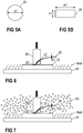
- Thick bonding wire in this context refers to a bonding wire 20 having a rounded cross section (see Figure 5A ) with a diameter d1 of at least 125 ⁇ m, or to a bonding wire 20 having a rectangular cross-section (see Figure 5B ) with a width w1 of at least 500 ⁇ m and a height h1 of at least 50 ⁇ m, for example.
- one end of the bonding wire is melted using high-voltage discharge, thereby forming a ball of soft material at one end of the bonding wire. This ball is then welded to the element that is to be electrically contacted.
- the bonding wire 20 in wedge bonding methods as described herein is not melted by use of high-voltage discharge to make it softer before pressing the bonding wire 20 to the first element 10.
- the bonding device 30 comprises a guiding element 32.
- the guiding element is configured to accommodate the bonding wire 20 or, in other words, the bonding wire 20 may be inserted into the guiding element 32.
- the bonding device 30 is configured to position the bonding wire 20 at a desired position with respect to the first element 10.
- the guiding element 32 may include a channel, for example. As is exemplarily illustrated in Figure 2 , a first end 22 of the bonding wire 20 may protrude from the guiding element 32. When lowering the bonding device 30 onto the first element 10, the first end 22 of the bonding wire 20 which protrudes from the guiding element 32 is arranged between the bonding device 30 and the first element 10.
- the first end 22 of the bonding wire 20 protrudes from the guiding element 32 at a desired position of the bonding device 30. Therefore, by positioning the bonding device 30 with respect to the first element 10, the first end 22 of the bonding wire 20 may also be precisely positioned with respect to the first element 10.
- the first end 22 of the bonding wire 20 is then pressed onto the first element 10 by applying a certain pressure with the bonding device 30. This pressure that is applied by the bonding device 30 is exemplarily illustrated by means of a bold arrow in Figure 2 . As has been described before, no ball is formed at the first end 22 of the bonding wire 20 before pressing the first end 22 to the first element 10.
- At least the first end 22 may additionally be exposed to ultrasonic energy, thereby deforming the first end 22 of the bonding wire 20 while pressing it to the first element 10 and creating a permanent substance-to-substance bond between the first end 22 of the bonding wire 20 and the first element 10. Additionally, the first element 10 may also be exposed, at least partly, to ultrasonic energy.
- the first element 10 may be electrically connected to a second element 12 via the bonding wire 20.
- a second end 24 of the bonding wire 20 may be connected (bonded) to the second element 12 in essentially the same way as has been described with respect to the first element 10 and the first end 22 of the bonding wire 20 before.
- the bonding wire 20 may be a continuous bonding wire 20 which is cut off at a desired location, thereby forming the second end 24, as is exemplarily illustrated in Figure 4 .
- the bonding wire 20 may be cut off after establishing the connection with the second element 12, when lifting the bonding device 30 from the second element 12, as is exemplarily illustrated by the bold arrow in Figure 4 .
- the second element 12 may be another semiconductor body or a semiconductor substrate, for example.
- Al wires are used for wedge bonding processes.
- Al-wires have several disadvantages.
- Other materials such as Copper (Cu), for example, provide better characteristics with regard to reliability and performance as compared to Al-wires. Copper, however, is generally harder than aluminum.
- Cu Copper
- the comparably hard Cu-wire on the first element 10 (or the second element 12) may lead to damages of the first element 10 (or the second element12).
- the first element 10 may comprise an electrically conductive layer (e.g., bond pad, not illustrated in Figures 1 to 4 ).
- Such an electrically conductive layer may comprise an electrically conducting material such as a metal, or a metal alloy, for example. If a Cu-wire is used, the electrically conductive layer often also comprises Copper. The first end 22 of the bonding wire 20 may be pressed on such an electrically conductive layer. If the first end 22 of the bonding wire 20 is pressed on the electrically conductive layer with relatively high pressure, however, the electrically conductive layer may be damaged. Therefore, generally ball bonding processes are used instead of wedge bonding processes when bonding Cu-wires.
- Figure 6 schematically illustrates an exemplary embodiment of a wedge-wedge bonding method that may be used for bonding Cu-wires.
- the bonding wire 20 that is exemplarily illustrated in Figure 6 may consist of or may include copper or a copper alloy, for example.
- the bonding wire 20 may be a thick bonding wire having a diameter d1 of at least 125 ⁇ m, or at least 200 ⁇ m, and at most 600 ⁇ m, for example. According to one example, the diameter d1 is between 125 ⁇ m and 600 ⁇ m.
- the bonding wire 20 may have a width w1 of at least 500 ⁇ m, at least 700 ⁇ m, at least 1000 ⁇ m, or at least 2000 ⁇ m, and at most 3000 ⁇ m, for example. According to one example, the width w1 is between 500 ⁇ m and 3000 ⁇ m.
- the bonding wire 20 having a rectangular cross section may have a height h1 of at least 50 ⁇ m, at least 100 ⁇ m, or at least 150 ⁇ m, and at most 400 ⁇ m, for example. According to one example, the height h1 is between 50 ⁇ m and 400 ⁇ m.
- the first element 10 and the first end 22 of the bonding wire 20 are heated while bonding the bonding wire 20 to the first element 10, that is, while applying pressure to the first end 22 of the bonding wire 20 and while further exposing the first end 22 of the bonding wire to ultrasonic energy.
- the first end 22 of the bonding wire 20 may be heated via the first element 10. That is, heat is applied to the first element 10 and is subsequently transferred to the first end 22 of the bonding wire 20.
- the first element 10 may be arranged on a heating device 40, as schematically illustrated in Figure 6 .
- the heating device 40 may be configured to heat the first element 10 and further to radiate heat to the surroundings of the element 10 and of the bonding wire 20.
- the inside of the bonding chamber may be heated by the heating device 40.
- Heating the first element 10 (and an optional electrically conductive layer arranged on the first element 10) and the first end 22 of the bonding wire 20 supports the bonding process.
- the components such as the bonding wire 20 or an electrically conductive layer provided on the first element 10, for example, may be formed or reshaped a lot easier than without heating. Heating the components that are to be bonded together further increases the friction value and, therefore, the energy transmission.
- the solidity (yield strength/tensile strength) of the components decreases with increasing temperature.
- the energy that is required for forming the bond between the bonding wire 20 and the first element 10 depends on the temperature of the components. If the temperature increases, the energy required for the bonding process decreases.
- the total energy that is required to form the bond between the bonding wire 20 and the element 10 is generally made up of normal force and ultrasonic energy.
- the probably most important advantage of applying heat to the components is the reduction of mechanical stress affecting the first element 10 (or the electrically conductive layer arranged on the first element 10).
- the materials of the bonding wire 20 and the electrically conductive layer commingle to a certain degree.
- a reduced mechanical stress results in a lower commingling of the materials of the different components. It is generally preferable that the materials commingle only to a comparably low degree.
- the reliability and the quality of the bond connection is at least the same as for conventional wedge-wedge bonding processes without heating, if not better.
- the bonding process may be performed in an ambient air environment.
- the wedge-wedge bonding process that has been described with respect to Figure 6 above, may also be carried out in a protective atmosphere (inert atmosphere), for example. That is, an inert protective gas 50 may be provided.
- the inert protective gas 50 may surround the bonding device 30, the bonding wire 20 as well as the first element 10.
- the inert protective gas 50 further assists the bonding process and further enhances the advantages that have been discussed above.
- the inert protective gas 50 functions as protection against oxidation of the metallic components. Heating the metallic components such as the bonding wire 20 and the electrically conductive layer may result in an oxidation of the surfaces of the metallic components if an oxidation protection is not provided.
- An oxidation of the surfaces of the bonding partners reduces the reliability of the bond that is formed between the bonding partners. At worst, an oxidation of the surfaces of the bonding partners may result in unwanted lift offs of the bonding wires.
- a reducing protection gas may be provided.
- a reducing protection gas may comprise, e.g., Ar, SF6 or H2, for example.
- any other suitable gases may be provided.
- an inert gas and a reducing protective gas may alter the tribological stress exerted on the bonding partners. In particular, such gases may positively alter the tribological stress such that the abrasion of the bonding partners may be reduced.
- the first element 10 may comprise a first layer 14 of electrically conducting material.
- the first layer 14 may function as a bond pad and the bonding wire 20 may be permanently connected to the first layer 14.
- the first layer 14 may comprise a metal such as Copper, for example.
- the first layer 14 may comprise the same material as the bonding wire 20 and may have a thickness d2 of less than 25 ⁇ m and at least 5 ⁇ m, for example.
- the first layer 14 may completely cover a surface of the first element, as is exemplarily illustrated in Figure 8 . This, however, is only an example. It is also possible that the first layer 14 only partly covers one of the surfaces of the first element 10.
- the material of the bonding wire 20 and the material of the first layer 14 may at least partly commingle during the bonding process, because of the hardness of the thick Cu-wire.
- the commingling of the materials of the first layer 14 and the bonding wire 20 may be reduced. Even for first layers 14 having a thickness d2 of at least 5 ⁇ m and less than 25 ⁇ m, at least 10% of the thickness d2 below the first end 22 of the bonding wire 20 may remain intact after bonding the bonding wire 20 to the first layer 14.
- the temperature of the first layer 14 and the bonding wire 20 may be, e.g., at least 80°C, at least 100°C, at least 150°C or at least 200°C, and at most 250°C.
- the bonding process is performed in a vacuum.
- the bonding partners e.g., first element 10, bonding wire 20
- the bonding device 30 may be arranged in a vacuum chamber while performing the bonding process.
- the vacuum together with the increased temperature, has a similarly positive effect as the inert gas and the reduced protective gas that have been described before.
- the thickness of the first layer 14 may be increased as compared to the arrangement that has been described with respect to Figure 8 before. This is exemplarily illustrated in Figure 9 .
- the thickness d3 of the first layer 14 may be greater than 25 ⁇ m, or greater than 50 ⁇ m, for example. If the thickness d2, d3 of the first layer 14 is increased, a larger percentage of the material of the first layer 14 that is arranged below the first end 22 of the bonding wire 20 remains intact after the bonding process. This means that the commingling of the material of the bonding wire 20 and the first layer 14 does not affect the whole thickness d2, d3 of the first layer 14.
- the thickness of the first layer 14 is increased to more than 50 ⁇ m, at least 50% or at least 60% of the thickness d2, d3 below the first end 22 may remain intact. However, it is also possible that more or less of the thickness d2, d3 below the first end 22 remain intact.
- the bonding device 30 illustrated in Figures 1 to 9 is only one example.
- the bonding device 30 may be implemented in any other suitable way.
- One further possible example is schematically illustrated in Figure 10 .
- the bonding device 30 may comprise a so-called wedge 34.
- the wedge 34 is mainly configured to apply a pressure to a bonding wire 20, thereby pressing the bonding wire 20 on the first element 10 to form the bonding connection.
- the bonding wire 20 may be held in place by a so-called wire guide 36.
- the bonding wire 20 may be led through the wire guide 36 and protrude from an opening in the wire guide 36.
- the wire guide 36 may be positioned in relation to the wedge 34.
- the wire guide 36 may be permanently coupled to the wedge 34 such that the wire guide 36 and the wedge 34 always perform the same movements and the wire guide 36 is always positioned in the same position with regard to the wedge 34.
- the bonding device 30 may further comprise a blade 38 for cutting the bonding wire 20, where required. Any other suitable implementations of the bonding device 30 are also possible.
- Figure 11 illustrates a cross-sectional view of a section of the first layer 14 and a first end 22 of a bonding wire 20 that is bonded to the first layer 14.
- the first layer has a thickness d3, as has been described with respect to Figure 9 before.
- the commingling of the materials is indicated with the dotted area. The commingling may occur in the first layer 14 as well as in the bonding wire 20.
- the first layer 14 may be seen as having a first sub-layer including only material of the first layer 14 and a second sub-layer including commingled material (material of the first layer 14 and the bonding wire 20 intermixed).
- the first sub-layer have a thickness d31 and the second sub-layer may have a thickness d32.
- the thickness d31 of the first sub-layer may be at least 10%, at least 50% or at least 60% of the thickness d3 of the first layer 14.
- the hardness of the first layer 14 may be chosen such that the wear of the first layer 14 is reduced.
- the hardness of the first layer 14 may be chosen depending on the hardness of the bonding wire 20.
- the bonding wire 20 may have a first hardness and the first layer 14 may have a second hardness, wherein the second hardness is greater than the first hardness.
- the second hardness may be ⁇ 150% of the first hardness.
- a greater hardness of the first layer 14 may be attained by alloying the material of the first layer 14, e.g., the copper of the first layer 14. Increasing the hardness of the first layer 14 with respect to the hardness of the bonding wire 20 reduces the tribological stress on the first layer 14.
- a greater hardness of the first layer 14 may be attained by adjusting the fine crystalline copper structure of the first layer 14.
- the grain size of the microstructure within the first layer 14 may be less than the thickness d2, d3 of the first layer 14.
- the arrangement may comprise a bonding chamber 60.
- the first element 10 may be arranged within the bonding chamber 60.
- a heating device 40 may form a bottom of the bonding chamber 60.
- the heating device 40 may be arranged within the bonding chamber 60.
- the first element 10 may be arranged on the bottom of the bonding chamber 60, e.g., on the heating device 60.
- the bonding device 30 that is configured to receive the bonding wire 20, to position the bonding wire 20 with respect to the first element 10, and to press the bonding wire to the first element 10 is arranged within the bonding chamber 60.
- the bonding device 30 may be coupled to a control unit 32.
- the bonding chamber 60 may comprise an opening 62.
- the bonding device 30 may protrude through the opening 62 to the outside of the bonding chamber 60.
- the opening 62 may be covered by a flexible cover 34, which may be a sort of bellows, for example.
- the flexible cover 34 may prevent a significant gas exchange between the inside and the outside of the bonding chamber 60. In this way, an inert gas or a reduced protective gas could be prevented from escaping the bonding chamber 60. Further, the flexible cover 34 which closes the bonding chamber 60 allows to create a vacuum within the bonding chamber 60.
- the bonding chamber 60 may comprise one or more gas inlets 64 that are configured to direct a gas such as an inert gas or a reducing protective gas into the bonding chamber 60.
- a gas such as an inert gas or a reducing protective gas
- the flow of gas inside the chamber 60 is exemplarily illustrated in Figure 12 by bold arrows.
- the flexible cover 34 may not completely seal the opening 62 of the bonding chamber 60. Therefore, some gas that is led into the chamber 60 though the gas inlets 64 may exit the chamber 60 through the flexible cover 34 or through gaps between the flexible cover 34 and the bonding chamber 60.
- the control unit 32 may protrude through an opening in the flexible cover 34, thereby closing the opening in the flexible cover 34.
- the control unit 32 and the bonding device 30 that is connected to the control unit 32 need to be moved in order to position the bonding wire 20 in relation to the first element 10.
- the flexible cover 34 allows such movements of the control unit 32 and the bonding device 30.
- An optional vacuum unit 70 may be arranged in the bottom of the bonding chamber 60.
- the vacuum unit 70 may be configured to create a vacuum, thereby drawing the first element 10 which is arranged above the vacuum unit 70 towards the bottom of the bonding chamber 60.
- the first element 10 may be firmly held in place during the bonding process when comparably large forces are exerted on the first element 10.
- the first element 10, however, may be held in place in any other suitable way.
- the bonding chamber 60 mainly functions as a gas cover. However, the bonding chamber 60 may be further configured to keep heat that is generated by the heating device inside a specified volume (inside the bonding chamber 60).
- FIG. 13 the opening 62 of the bonding chamber 60 may be covered with a brush protection cap 36.
- FIGs 14A and 14B schematically illustrate top views of different implementations of a brush protection cap 36.
- a multiplicity of bristles 38 protrudes from a first side into the opening 62, thereby essentially covering the opening.
- a brush protection cap 36 generally does not provide a gas tight cover for the opening 62. Therefore, gas that is led into the chamber 60 may exit the chamber 60 though openings between the bristles 38 of the brush protection cap36. This is schematically illustrated with bold arrows in Figure 13 .
- the control unit 32 may be arranged outside the bonding chamber 60.
- the bonding device 30 may protrude through the bristles 38 into the bonding chamber 60.
- the flexible bristles 38 allow the bonding device 30 to move in order to position the bonding wire 20.
- bristles 38 may protrude into the opening 62 from two different sides. In the example of Figure 14B , the bristles do not overlap. This, however, is only an example. According to another example, the bristles 38 protruding from different sides of the opening 62 may overlap. Further, the bristles 38 may be arranged in any other suitable way, thereby covering the opening 62 and allowing a movement of the bonding device 30.
- the arrangement is arranged within a closed bonding chamber 66.
- the closed chamber 66 may be filled with gas through gas inlets 64.
- a vacuum may be generated within the closed chamber 66, as is exemplarily illustrated in Figure 16 .
- the main components of the arrangements illustrated in Figures 12 , 13, 14, 15 and 16 are identical or similar to each other. Therefore, in the foregoing description focus is laid on the differences between the different embodiments.
Abstract
Description
- The instant disclosure relates to arrangements and to a method for providing a bond connection, in particular for providing a bond connection for electrically connecting elements of a power semiconductor module.
- Power semiconductor module arrangements often include a base plate within a housing and at least one substrate is arranged on the base plate. Other power semiconductor module arrangements may solely include a substrate (e.g. Cu-ceramic-Cu substrate) without a base plate. A semiconductor arrangement including a plurality of controllable semiconductor components (e.g., two IGBTs in a half-bridge configuration) is usually arranged on each of the at least one substrates. Each substrate usually comprises a substrate layer (e.g., a ceramic layer), a first metallization layer deposited on a first side of the substrate layer and a second metallization layer deposited on a second side of the substrate layer. The controllable semiconductor components are mounted, for example, on the first metallization layer. The second metallization layer is usually attached to the base plate. Other substrates are known including multiple substrate and metal layers stacked on each other, with buried metal layers acting either as shielding layers or being part of the electronic circuit and electrically connected to other metal layers by means of through contacts. The electrical connections between the semiconductor components and the first metallization layer, between different semiconductor components, between the first metallization layers of different substrates, or between any other elements of the power semiconductor module arrangement often comprise bonding wires. The bonding wire is usually bonded to an electrically conductive surface or bond pad arranged on the component that is to be electrically contacted.
- Several different methods for establishing a permanent electrical connection or bond between a bonding wire and an electrically conductive surface are known. Such known method include the so-called wedge bonding, or wedge/wedge bonding. Wedge bonding processes usually utilize ultrasonic energy and pressure to create a bond between the bonding wire, which is usually a thick wire, and the bond pad. Wedge bonding processes are generally low temperature processes which are performed at room temperature. Usually Al-wires (aluminum wires) are used for wedge bonding processes. Bonding wires including other materials such as Cu (copper), for example, are generally preferred with respect to reliability and performance. However, Cu-wires are generally harder than Al-wires. The bond pad usually needs to include other materials than aluminum when using Cu-wires. That is because the hardness of aluminum bond pads is generally not sufficient for the comparably hard Cu-wires, therefore, the bond pad should include a material that is harder than aluminum. Further, for Cu-wires an increased ultrasonic power has to be provided as compared to wedge bonding processes using Al-wires. Even further, the time for performing the wedge bonding process is increased and the Cu-wire needs to be pressed on the bond pad with a larger strength as compared to a wedge bond process using Al-wires and Al-bond pads. This increased strength (or force) may result in severe damages of the bond pad material, for example.
- There is a need for an improved method which provides a stable and durable connection between a bonding wire and the element that is to be electrically contacted.
- A method includes heating a first electrically conductive layer that is to be electrically contacted, and that is arranged on a first element, and pressing a first end of a bonding wire on the first electrically conductive layer by exerting pressure to the first end of the bonding wire, and further by exposing the first end of the bonding wire to ultrasonic energy, thereby deforming the first end of the bonding wire and creating a permanent substance-to-substance bond between the first end of the bonding wire and the first electrically conductive layer. The bonding wire either comprises a rounded cross section with a diameter of at least 125µm or a rectangular cross section with a first width of at least 500µm and a first height of at least 50µm.
- An arrangement is described for establishing a permanent bond connection between a bonding wire and a first electrically conductive surface of a first element. The arrangement includes a bonding chamber, a bonding device arranged within the bonding chamber, wherein the bonding device is configured to press a first end of the bonding wire on the first electrically conductive surface, and a heating device, configured to heat the first layer and the first end of the bonding wire. The arrangement is configured to establish a connection between the first surface and a bonding wire, the bonding wire comprising either a rounded cross section with a diameter of at least 125µm, or a rectangular cross section with a first width of at least 500µm and a first height of at least 50µm
- The invention may be better understood with reference to the following drawings and the description. The components in the figures are not necessarily to scale, emphasis is instead being placed upon illustrating the principles of the invention. Moreover, in the figures, like referenced numerals designate corresponding parts throughout the different views.
-
-
Figures 1 to 4 schematically illustrate several steps of a typical wedge bond process. -
Figure 5 , includingFigures 5A and 5B , schematically illustrates different cross sections of a bonding wire. -
Figure 6 schematically illustrates an exemplary method for providing a bond connection. -
Figure 7 schematically illustrates another exemplary method for providing a bond connection. -
Figure 8 schematically illustrates another exemplary method for providing a bond connection. -
Figure 9 schematically illustrates another exemplary method for providing a bond connection. -
Figure 10 schematically illustrates an exemplary bonding device. -
Figure 11 schematically illustrates the commingling of the materials of different bonding partners. -
Figure 12 schematically illustrates a cross-sectional view of an exemplary arrangement for providing a bond connection. -
Figure 13 schematically illustrates a cross-sectional view of another exemplary arrangement for providing a bond connection. -
Figure 14 , includingFigures 14A and 14B , schematically illustrates a top view on the opening provided in the chamber illustrated inFigure 13 . -
Figure 15 schematically illustrates a cross-sectional view of another exemplary arrangement for providing a bond connection. -
Figure 16 schematically illustrates a cross-sectional view of another exemplary arrangement for providing a bond connection. - In the following detailed description, reference is made to the accompanying drawings. The drawings show specific examples in which the invention may be practiced. It is to be understood that the features and principles described with respect to the various examples may be combined with each other, unless specifically noted otherwise. In the description as well as in the claims, designations of certain elements as "first element", "second element", "third element" etc. are not to be understood as enumerative. Instead, such designations serve solely to address different "elements". That is, e.g., the existence of a "third element" does not require the existence of a "first element" and a "second element". A semiconductor body as described herein may be made from (doped) semiconductor material and may be a semiconductor chip or be included in a semiconductor chip. A semiconductor body has electrically connecting pads and includes at least one semiconductor element with electrodes.
- Referring to
Figures 1 to 4 , the general principle of a method for establishing a connection (a bond) between abonding wire 20 and anelement 10 that is to be electrically contacted is schematically illustrated. Generally, different bonding methods are known such as the so-called ball bonding, ball-wedge bonding, wedge bonding, or wedge-wedge bonding, for example. The present example refers to a wedge-wedge bonding method. -
Figure 1 schematically illustrates afirst element 10 that is to be electrically contacted, and abonding device 30. Thefirst element 10 may be or may comprise a semiconductor body, for example. In power semiconductor module arrangements usually one or more semiconductor bodies are arranged on a semiconductor substrate. Each of the semiconductor bodies arranged on a semiconductor substrate may include a diode, an IGBT (Insulated-Gate Bipolar Transistor), a MOSFET (Metal-Oxide-Semiconductor Field-Effect Transistor), a JFET (Junction Field-Effect Transistor), a HEMT (High-Electron-Mobility Transistor), or any other suitable controllable semiconductor element. One or more semiconductor bodies may form a semiconductor arrangement on the semiconductor substrate. This, however, is only an example. Thefirst element 10 may be any element, e.g., of a power semiconductor module arrangement, that is to be electrically contacted with abonding wire 20. - According to another example, the
first element 10 may be a semiconductor substrate. A semiconductor substrate usually includes a dielectric insulation layer, a (structured) first metallization layer attached to the dielectric insulation layer, and a second (structured) metallization layer attached to the dielectric insulation layer. The dielectric insulation layer is disposed between the first and second metallization layers. Each of the first and second metallization layers may consist of or include one of the following materials: copper; a copper alloy; aluminum; an aluminum alloy; any other metal or alloy that remains solid during the operation of the power semiconductor module arrangement. A semiconductor substrate may be a ceramic substrate, that is, a substrate in which the dielectric insulation layer is a ceramic, e.g., a thin ceramic layer. The ceramic may consist of or include one of the following materials: aluminum oxide; aluminum nitride; zirconium oxide; silicon nitride; boron nitride; or any other dielectric ceramic. For example, the dielectric insulation layer may consist of or include one of the following materials: Al2O3, AlN, BN, or Si3N4. For instance, a substrate may, e.g., be a Direct Copper Bonding (DCB) substrate, a Direct Aluminum Bonding (DAB) substrate, or an Active Metal Brazing (AMB) substrate. A substrate may also be a conventional printed circuit board (PCB) having a non-ceramic dielectric insulation layer. For instance, a non-ceramic dielectric insulation layer may consist of or include a cured resin. Thebonding wire 20 may be permanently connected to one of the first and second metallization layers, e.g., to the first metallization layer. - A
bonding wire 20 is inserted into thebonding device 30. Thebonding wire 20 may be any suitable electrically conductive wire, e.g., a metal wire. For wedge-wedge bonding methods, usually thick bonding wires are used. Thick bonding wire in this context refers to abonding wire 20 having a rounded cross section (seeFigure 5A ) with a diameter d1 of at least 125µm, or to abonding wire 20 having a rectangular cross-section (seeFigure 5B ) with a width w1 of at least 500µm and a height h1 of at least 50µm, for example. For the purpose of explanation it should be mentioned that in ball bonding methods, one end of the bonding wire is melted using high-voltage discharge, thereby forming a ball of soft material at one end of the bonding wire. This ball is then welded to the element that is to be electrically contacted. As compared to ball bonding methods, thebonding wire 20 in wedge bonding methods as described herein is not melted by use of high-voltage discharge to make it softer before pressing thebonding wire 20 to thefirst element 10. - The
bonding device 30 comprises a guidingelement 32. The guiding element is configured to accommodate thebonding wire 20 or, in other words, thebonding wire 20 may be inserted into the guidingelement 32. Thebonding device 30 is configured to position thebonding wire 20 at a desired position with respect to thefirst element 10. The guidingelement 32 may include a channel, for example. As is exemplarily illustrated inFigure 2 , afirst end 22 of thebonding wire 20 may protrude from the guidingelement 32. When lowering thebonding device 30 onto thefirst element 10, thefirst end 22 of thebonding wire 20 which protrudes from the guidingelement 32 is arranged between thebonding device 30 and thefirst element 10. Thefirst end 22 of thebonding wire 20 protrudes from the guidingelement 32 at a desired position of thebonding device 30. Therefore, by positioning thebonding device 30 with respect to thefirst element 10, thefirst end 22 of thebonding wire 20 may also be precisely positioned with respect to thefirst element 10. Thefirst end 22 of thebonding wire 20 is then pressed onto thefirst element 10 by applying a certain pressure with thebonding device 30. This pressure that is applied by thebonding device 30 is exemplarily illustrated by means of a bold arrow inFigure 2 . As has been described before, no ball is formed at thefirst end 22 of thebonding wire 20 before pressing thefirst end 22 to thefirst element 10. When pressing thefirst end 22 on thefirst element 10 and applying a force to thefirst end 22, at least thefirst end 22 may additionally be exposed to ultrasonic energy, thereby deforming thefirst end 22 of thebonding wire 20 while pressing it to thefirst element 10 and creating a permanent substance-to-substance bond between thefirst end 22 of thebonding wire 20 and thefirst element 10. Additionally, thefirst element 10 may also be exposed, at least partly, to ultrasonic energy. - As is exemplarily illustrated in
Figure 3 , thefirst element 10 may be electrically connected to asecond element 12 via thebonding wire 20. Asecond end 24 of thebonding wire 20 may be connected (bonded) to thesecond element 12 in essentially the same way as has been described with respect to thefirst element 10 and thefirst end 22 of thebonding wire 20 before. Thebonding wire 20 may be acontinuous bonding wire 20 which is cut off at a desired location, thereby forming thesecond end 24, as is exemplarily illustrated inFigure 4 . Thebonding wire 20 may be cut off after establishing the connection with thesecond element 12, when lifting thebonding device 30 from thesecond element 12, as is exemplarily illustrated by the bold arrow inFigure 4 . Thesecond element 12 may be another semiconductor body or a semiconductor substrate, for example. - Usually, aluminum (Al) wires are used for wedge bonding processes. However, the use of Al-wires has several disadvantages. Other materials such as Copper (Cu), for example, provide better characteristics with regard to reliability and performance as compared to Al-wires. Copper, however, is generally harder than aluminum. When using Cu-wires, therefore, more pressure needs to be applied to the first end 22 (or second end 24) of a Cu-wire as compared to Al-wires. Pressing the comparably hard Cu-wire on the first element 10 (or the second element 12) may lead to damages of the first element 10 (or the second element12). For example, the
first element 10 may comprise an electrically conductive layer (e.g., bond pad, not illustrated inFigures 1 to 4 ). Such an electrically conductive layer may comprise an electrically conducting material such as a metal, or a metal alloy, for example. If a Cu-wire is used, the electrically conductive layer often also comprises Copper. Thefirst end 22 of thebonding wire 20 may be pressed on such an electrically conductive layer. If thefirst end 22 of thebonding wire 20 is pressed on the electrically conductive layer with relatively high pressure, however, the electrically conductive layer may be damaged. Therefore, generally ball bonding processes are used instead of wedge bonding processes when bonding Cu-wires. -
Figure 6 schematically illustrates an exemplary embodiment of a wedge-wedge bonding method that may be used for bonding Cu-wires. Thebonding wire 20 that is exemplarily illustrated inFigure 6 may consist of or may include copper or a copper alloy, for example. Thebonding wire 20 may be a thick bonding wire having a diameter d1 of at least 125µm, or at least 200µm, and at most 600µm, for example. According to one example, the diameter d1 is between 125µm and 600µm. If thebonding wire 20 has a rectangular cross section instead of a round cross section, thebonding wire 20 may have a width w1 of at least 500µm, at least 700µm, at least 1000µm, or at least 2000µm, and at most 3000µm, for example. According to one example, the width w1 is between 500µm and 3000µm. Thebonding wire 20 having a rectangular cross section may have a height h1 of at least 50µm, at least 100µm, or at least 150µm, and at most 400µm, for example. According to one example, the height h1 is between 50µm and 400µm. - As is schematically illustrated in
Figure 6 , thefirst element 10 and thefirst end 22 of thebonding wire 20 are heated while bonding thebonding wire 20 to thefirst element 10, that is, while applying pressure to thefirst end 22 of thebonding wire 20 and while further exposing thefirst end 22 of the bonding wire to ultrasonic energy. For example, thefirst end 22 of thebonding wire 20 may be heated via thefirst element 10. That is, heat is applied to thefirst element 10 and is subsequently transferred to thefirst end 22 of thebonding wire 20. For example, thefirst element 10 may be arranged on aheating device 40, as schematically illustrated inFigure 6 . Theheating device 40 may be configured to heat thefirst element 10 and further to radiate heat to the surroundings of theelement 10 and of thebonding wire 20. For example, if thefirst element 10 and thebonding wire 20 are arranged in a bonding chamber (not illustrated inFigure 6 ), the inside of the bonding chamber may be heated by theheating device 40. Heating the first element 10 (and an optional electrically conductive layer arranged on the first element 10) and thefirst end 22 of thebonding wire 20 supports the bonding process. When heated, the components such as thebonding wire 20 or an electrically conductive layer provided on thefirst element 10, for example, may be formed or reshaped a lot easier than without heating. Heating the components that are to be bonded together further increases the friction value and, therefore, the energy transmission. The solidity (yield strength/tensile strength) of the components decreases with increasing temperature. The energy that is required for forming the bond between thebonding wire 20 and thefirst element 10 depends on the temperature of the components. If the temperature increases, the energy required for the bonding process decreases. The total energy that is required to form the bond between thebonding wire 20 and theelement 10 is generally made up of normal force and ultrasonic energy. - However, the probably most important advantage of applying heat to the components is the reduction of mechanical stress affecting the first element 10 (or the electrically conductive layer arranged on the first element 10). When pressing the
bonding wire 20 on an electrically conductive layer, the materials of thebonding wire 20 and the electrically conductive layer commingle to a certain degree. A reduced mechanical stress results in a lower commingling of the materials of the different components. It is generally preferable that the materials commingle only to a comparably low degree. The reliability and the quality of the bond connection, however, is at least the same as for conventional wedge-wedge bonding processes without heating, if not better. - The bonding process may be performed in an ambient air environment. As is exemplarily illustrated in
Figure 7 , the wedge-wedge bonding process that has been described with respect toFigure 6 above, may also be carried out in a protective atmosphere (inert atmosphere), for example. That is, an inertprotective gas 50 may be provided. The inertprotective gas 50 may surround thebonding device 30, thebonding wire 20 as well as thefirst element 10. The inertprotective gas 50 further assists the bonding process and further enhances the advantages that have been discussed above. Further, the inertprotective gas 50 functions as protection against oxidation of the metallic components. Heating the metallic components such as thebonding wire 20 and the electrically conductive layer may result in an oxidation of the surfaces of the metallic components if an oxidation protection is not provided. An oxidation of the surfaces of the bonding partners reduces the reliability of the bond that is formed between the bonding partners. At worst, an oxidation of the surfaces of the bonding partners may result in unwanted lift offs of the bonding wires. - Performing the bonding process in an inert gas atmosphere, however, is only an example. Instead of an inert gas, a reducing protection gas may be provided. A reducing protection gas may comprise, e.g., Ar, SF6 or H2, for example. Alternatively, any other suitable gases may be provided. Both, an inert gas and a reducing protective gas, may alter the tribological stress exerted on the bonding partners. In particular, such gases may positively alter the tribological stress such that the abrasion of the bonding partners may be reduced. As is exemplarily illustrated in
Figure 8 and as has been explained above, thefirst element 10 may comprise afirst layer 14 of electrically conducting material. Thefirst layer 14 may function as a bond pad and thebonding wire 20 may be permanently connected to thefirst layer 14. As has been described before, thefirst layer 14 may comprise a metal such as Copper, for example. Thefirst layer 14 may comprise the same material as thebonding wire 20 and may have a thickness d2 of less than 25µm and at least 5µm, for example. Thefirst layer 14 may completely cover a surface of the first element, as is exemplarily illustrated inFigure 8 . This, however, is only an example. It is also possible that thefirst layer 14 only partly covers one of the surfaces of thefirst element 10. - As has been described above, the material of the
bonding wire 20 and the material of thefirst layer 14 may at least partly commingle during the bonding process, because of the hardness of the thick Cu-wire. By heating thefirst layer 14 and thebonding wire 20, e.g., with the heating arrangement that has been described with respect toFigure 6 above, the commingling of the materials of thefirst layer 14 and thebonding wire 20 may be reduced. Even forfirst layers 14 having a thickness d2 of at least 5µm and less than 25µm, at least 10% of the thickness d2 below thefirst end 22 of thebonding wire 20 may remain intact after bonding thebonding wire 20 to thefirst layer 14. Remaining intact in this context means that the material does not commingle with the material of thebonding wire 20. This reduced commingling may be further supported by providing a protective gas atmosphere, as has been described with respect toFigure 7 above. The temperature of thefirst layer 14 and thebonding wire 20 may be, e.g., at least 80°C, at least 100°C, at least 150°C or at least 200°C, and at most 250°C. - According to an even further example, the bonding process is performed in a vacuum. For example, the bonding partners (e.g.,
first element 10, bonding wire 20) and thebonding device 30 may be arranged in a vacuum chamber while performing the bonding process. The vacuum, together with the increased temperature, has a similarly positive effect as the inert gas and the reduced protective gas that have been described before. - According to an even further example, the thickness of the
first layer 14 may be increased as compared to the arrangement that has been described with respect toFigure 8 before. This is exemplarily illustrated inFigure 9 . The thickness d3 of thefirst layer 14 may be greater than 25µm, or greater than 50µm, for example. If the thickness d2, d3 of thefirst layer 14 is increased, a larger percentage of the material of thefirst layer 14 that is arranged below thefirst end 22 of thebonding wire 20 remains intact after the bonding process. This means that the commingling of the material of thebonding wire 20 and thefirst layer 14 does not affect the whole thickness d2, d3 of thefirst layer 14. For example, if the thickness of thefirst layer 14 is increased to more than 50µm, at least 50% or at least 60% of the thickness d2, d3 below thefirst end 22 may remain intact. However, it is also possible that more or less of the thickness d2, d3 below thefirst end 22 remain intact. - The
bonding device 30 illustrated inFigures 1 to 9 is only one example. Thebonding device 30 may be implemented in any other suitable way. One further possible example is schematically illustrated inFigure 10 . As is illustrated inFigure 10 , thebonding device 30 may comprise a so-calledwedge 34. Thewedge 34 is mainly configured to apply a pressure to abonding wire 20, thereby pressing thebonding wire 20 on thefirst element 10 to form the bonding connection. Thebonding wire 20 may be held in place by a so-calledwire guide 36. In particular, thebonding wire 20 may be led through thewire guide 36 and protrude from an opening in thewire guide 36. Thewire guide 36 may be positioned in relation to thewedge 34. For example, thewire guide 36 may be permanently coupled to thewedge 34 such that thewire guide 36 and thewedge 34 always perform the same movements and thewire guide 36 is always positioned in the same position with regard to thewedge 34. Thebonding device 30 may further comprise ablade 38 for cutting thebonding wire 20, where required. Any other suitable implementations of thebonding device 30 are also possible. - The commingling of the materials of different bonding partners is exemplarily illustrated in
Figure 11. Figure 11 illustrates a cross-sectional view of a section of thefirst layer 14 and afirst end 22 of abonding wire 20 that is bonded to thefirst layer 14. The first layer has a thickness d3, as has been described with respect toFigure 9 before. The commingling of the materials is indicated with the dotted area. The commingling may occur in thefirst layer 14 as well as in thebonding wire 20. In the area below thefirst end 22 of thebonding wire 20, thefirst layer 14 may be seen as having a first sub-layer including only material of thefirst layer 14 and a second sub-layer including commingled material (material of thefirst layer 14 and thebonding wire 20 intermixed). The first sub-layer have a thickness d31 and the second sub-layer may have a thickness d32. As has been described above, the thickness d31 of the first sub-layer may be at least 10%, at least 50% or at least 60% of the thickness d3 of thefirst layer 14. - According to a further example, the hardness of the
first layer 14 may be chosen such that the wear of thefirst layer 14 is reduced. For example, the hardness of thefirst layer 14 may be chosen depending on the hardness of thebonding wire 20. Thebonding wire 20 may have a first hardness and thefirst layer 14 may have a second hardness, wherein the second hardness is greater than the first hardness. For example, the second hardness may be ≥150% of the first hardness. A greater hardness of thefirst layer 14 may be attained by alloying the material of thefirst layer 14, e.g., the copper of thefirst layer 14. Increasing the hardness of thefirst layer 14 with respect to the hardness of thebonding wire 20 reduces the tribological stress on thefirst layer 14. - According to another example, a greater hardness of the
first layer 14 may be attained by adjusting the fine crystalline copper structure of thefirst layer 14. For example, the grain size of the microstructure within thefirst layer 14 may be less than the thickness d2, d3 of thefirst layer 14. - Now referring to
Figure 12 , an arrangement that may be used to perform a bonding process as has been described with respect toFigures 1 to 9 above is exemplarily illustrated. For example, the arrangement may comprise abonding chamber 60. Thefirst element 10 may be arranged within thebonding chamber 60. Aheating device 40 may form a bottom of thebonding chamber 60. This, however, is only an example. According to another example, theheating device 40 may be arranged within thebonding chamber 60. Thefirst element 10 may be arranged on the bottom of thebonding chamber 60, e.g., on theheating device 60. Thebonding device 30 that is configured to receive thebonding wire 20, to position thebonding wire 20 with respect to thefirst element 10, and to press the bonding wire to thefirst element 10 is arranged within thebonding chamber 60. Thebonding device 30 may be coupled to acontrol unit 32. Thebonding chamber 60 may comprise anopening 62. Thebonding device 30 may protrude through theopening 62 to the outside of thebonding chamber 60. Theopening 62 may be covered by aflexible cover 34, which may be a sort of bellows, for example. Theflexible cover 34 may prevent a significant gas exchange between the inside and the outside of thebonding chamber 60. In this way, an inert gas or a reduced protective gas could be prevented from escaping thebonding chamber 60. Further, theflexible cover 34 which closes thebonding chamber 60 allows to create a vacuum within thebonding chamber 60. - The
bonding chamber 60 may comprise one ormore gas inlets 64 that are configured to direct a gas such as an inert gas or a reducing protective gas into thebonding chamber 60. The flow of gas inside thechamber 60 is exemplarily illustrated inFigure 12 by bold arrows. Theflexible cover 34 may not completely seal theopening 62 of thebonding chamber 60. Therefore, some gas that is led into thechamber 60 though thegas inlets 64 may exit thechamber 60 through theflexible cover 34 or through gaps between theflexible cover 34 and thebonding chamber 60. Thecontrol unit 32 may protrude through an opening in theflexible cover 34, thereby closing the opening in theflexible cover 34. Thecontrol unit 32 and thebonding device 30 that is connected to thecontrol unit 32 need to be moved in order to position thebonding wire 20 in relation to thefirst element 10. Theflexible cover 34 allows such movements of thecontrol unit 32 and thebonding device 30. - An
optional vacuum unit 70 may be arranged in the bottom of thebonding chamber 60. Thevacuum unit 70 may be configured to create a vacuum, thereby drawing thefirst element 10 which is arranged above thevacuum unit 70 towards the bottom of thebonding chamber 60. In this way, thefirst element 10 may be firmly held in place during the bonding process when comparably large forces are exerted on thefirst element 10. Thefirst element 10, however, may be held in place in any other suitable way. Thebonding chamber 60 mainly functions as a gas cover. However, thebonding chamber 60 may be further configured to keep heat that is generated by the heating device inside a specified volume (inside the bonding chamber 60). - Now referring to
Figure 13 , according to another example theopening 62 of thebonding chamber 60 may be covered with abrush protection cap 36.Figures 14A and 14B schematically illustrate top views of different implementations of abrush protection cap 36. According to a first example, a multiplicity ofbristles 38 protrudes from a first side into theopening 62, thereby essentially covering the opening. Abrush protection cap 36 generally does not provide a gas tight cover for theopening 62. Therefore, gas that is led into thechamber 60 may exit thechamber 60 though openings between thebristles 38 of the brush protection cap36. This is schematically illustrated with bold arrows inFigure 13 . Thecontrol unit 32 may be arranged outside thebonding chamber 60. Thebonding device 30 may protrude through thebristles 38 into thebonding chamber 60. The flexible bristles 38 allow thebonding device 30 to move in order to position thebonding wire 20. As is schematically illustrated inFigure 14B , bristles 38 may protrude into the opening 62 from two different sides. In the example ofFigure 14B , the bristles do not overlap. This, however, is only an example. According to another example, thebristles 38 protruding from different sides of theopening 62 may overlap. Further, thebristles 38 may be arranged in any other suitable way, thereby covering theopening 62 and allowing a movement of thebonding device 30. - According to another example which is exemplarily illustrated in
Figure 15 , the arrangement is arranged within aclosed bonding chamber 66. This means that thebonding device 30 and thecontrol unit 32 are also completely arranged within theclosed chamber 66. This allows for providing abonding chamber 66 which is more leakproof to gases than the arrangements illustrated inFigures 12 and13 above. Theclosed chamber 66 may be filled with gas throughgas inlets 64. According to another example, a vacuum may be generated within theclosed chamber 66, as is exemplarily illustrated inFigure 16 . The main components of the arrangements illustrated inFigures 12 ,13, 14, 15 and16 are identical or similar to each other. Therefore, in the foregoing description focus is laid on the differences between the different embodiments.
Claims (15)
- A method comprising:heating a first electrically conductive layer (14) that is to be electrically contacted, and that is arranged on a first element (10); andpressing a first end (22) of a bonding wire (20) on the first electrically conductive layer (14) by exerting pressure to the first end (22) of the bonding wire (20), and further by exposing the first end (22) of the bonding wire (20) to ultrasonic energy, thereby deforming the first end (22) of the bonding wire (20) and creating a permanent substance-to-substance bond between the first end (22) of the bonding wire (20) and the first electrically conductive layer (14); whereinthe bonding wire (20) either comprises a rounded cross section with a diameter (d1) of at least 125µm or a rectangular cross section with a first width (w1) of at least 500µm and a first height (h1) of at least 50µm.
- The method of claim 1, further comprising
establishing a wedge-wedge bond connection between the bonding wire (20) and the first layer (14). - The method of claim 1 or 2, further comprising heating the first electrically conductive layer (14) to a temperature of between 80°C and 250°C, between 100°C and 250°C, or between 150°C and 250°C.
- The method of any of claims 1 to 3, further comprising
providing an inert gas, a reducing protective gas, or a vacuum in the surroundings of the first layer (14) and the first end (22) of the bonding wire (20). - The method of any of claims 1 to 4, wherein the first layer (14) has a thickness (d2, d3) of at least 5µm, at least 25µm, or at least 50µm.
- The method of any of claims 1 to 5, wherein the bonding wire (20) has a first hardness and the first layer (14) has a second hardness, wherein the second hardness is greater than the first hardness.
- The method of claim 6, wherein the second hardness is ≥150% of the first hardness.
- The method of claim 6 or 7, wherein the bonding wire (20) comprises a first material, and the first layer (14) comprises an alloy of the first material.
- The method of any of the preceding claims, wherein the bonding wire (20) comprises copper.
- The method of any of the preceding claims, further comprising
inserting the bonding wire (20) into a guiding element (32, 36) of a bonding device (30), wherein the bonding device (30) is configured to position the first end (22) of the bonding wire (20) at a desired position with respect to the first element (10), and to press the first end (22) of the bonding wire (20) on the first element (10) at the desired position. - An arrangement for establishing a permanent bond connection between a bonding wire (20) and a first electrically conductive surface (14) of a first element (10), the arrangement comprising:a bonding chamber (60, 66);a bonding device (30) arranged within the bonding chamber (60, 66), wherein the bonding device (30) is configured to press a first end (22) of the bonding wire (20) on the first electrically conductive surface (14); anda heating device (40), configured to heat the first layer (14) and the first end (22) of the bonding wire (20), whereinthe arrangement is configured to establish a connection between the first surface (14) and a bonding wire (20), the bonding wire (20) comprising either a rounded cross section with a diameter (d1) of at least 125µm, or a rectangular cross section with a first width (w1) of at least 500µm and a first height (h1) of at least 50µm.
- The arrangement of claim 11, wherein the bonding device (30) is further configured to establishing a wedge-wedge bond connection between the bonding wire (20) and the first layer (14).
- The arrangement of claim 11 or 12, wherein the bonding chamber (60) comprises an opening (62) and the bonding device (30) protrudes through the opening (30).
- The arrangement of claim 13, further comprising a cover that is configured to cover the opening (62) of the bonding chamber (60), wherein the cover comprises
a flexible cover (34) configured to prevent a significant gas exchange between the inside and the outside of the bonding chamber (60), wherein the bonding device (30) is coupled to the flexible cover (34) via a control unit (32), and wherein the flexible cover (34) allows a movement of the bonding device (30); or
a brush protection cap (36) configured to cover the opening (62), wherein the bonding device (30) protrudes through the brush protection cap (36), and wherein the brush protection cap (36) allows a movement of the bonding device (30). - The arrangement of any of claims 11 to 14, wherein the bonding chamber (60, 66) further comprises at least one gas inlet (64) configured to direct an inert gas or a reducing protective gas into the bonding chamber (60).
Priority Applications (3)
| Application Number | Priority Date | Filing Date | Title |
|---|---|---|---|
| EP18165648.9A EP3550596A1 (en) | 2018-04-04 | 2018-04-04 | Arrangements and method for providing a wire bond connection |
| CN201910268058.7A CN110349873A (en) | 2018-04-04 | 2019-04-03 | The device and method of engagement connection are provided |
| US16/374,043 US20190312008A1 (en) | 2018-04-04 | 2019-04-03 | Arrangements and Method for Providing a Bond Connection |
Applications Claiming Priority (1)
| Application Number | Priority Date | Filing Date | Title |
|---|---|---|---|
| EP18165648.9A EP3550596A1 (en) | 2018-04-04 | 2018-04-04 | Arrangements and method for providing a wire bond connection |
Publications (1)
| Publication Number | Publication Date |
|---|---|
| EP3550596A1 true EP3550596A1 (en) | 2019-10-09 |
Family
ID=61906646
Family Applications (1)
| Application Number | Title | Priority Date | Filing Date |
|---|---|---|---|
| EP18165648.9A Pending EP3550596A1 (en) | 2018-04-04 | 2018-04-04 | Arrangements and method for providing a wire bond connection |
Country Status (3)
| Country | Link |
|---|---|
| US (1) | US20190312008A1 (en) |
| EP (1) | EP3550596A1 (en) |
| CN (1) | CN110349873A (en) |
Citations (7)
| Publication number | Priority date | Publication date | Assignee | Title |
|---|---|---|---|---|
| JPS57190328A (en) * | 1981-05-19 | 1982-11-22 | Oki Electric Ind Co Ltd | Wire bonding method for copper lead |
| JPH01296637A (en) * | 1988-05-24 | 1989-11-30 | Kyocera Corp | Wire bonding device for hybrid integrated circuit |
| US20040217488A1 (en) * | 2003-05-02 | 2004-11-04 | Luechinger Christoph B. | Ribbon bonding |
| US20050150932A1 (en) * | 2002-02-11 | 2005-07-14 | Khalil Hosseini | Arrangement for wire bonding and method for producing a bonding connection |
| JP2013171964A (en) * | 2012-02-21 | 2013-09-02 | Ultrasonic Engineering Co Ltd | Ultrasonic wire bonding device and ultrasonic wire bonding method |
| US20150243534A1 (en) * | 2014-02-26 | 2015-08-27 | Lsi Corporation | Copper Wire Bonding Apparatus Using A Purge Gas to Enhance Ball Bond Reliability |
| US20150380368A1 (en) * | 2013-04-25 | 2015-12-31 | Fuji Electric Co., Ltd. | Semiconductor device and method for manufacturing the semiconductor device |
Family Cites Families (1)
| Publication number | Priority date | Publication date | Assignee | Title |
|---|---|---|---|---|
| CN101369545B (en) * | 2007-08-14 | 2011-07-20 | 三星电子株式会社 | Heating block and wire bonding method using the same |
-
2018
- 2018-04-04 EP EP18165648.9A patent/EP3550596A1/en active Pending
-
2019
- 2019-04-03 CN CN201910268058.7A patent/CN110349873A/en active Pending
- 2019-04-03 US US16/374,043 patent/US20190312008A1/en not_active Abandoned
Patent Citations (7)
| Publication number | Priority date | Publication date | Assignee | Title |
|---|---|---|---|---|
| JPS57190328A (en) * | 1981-05-19 | 1982-11-22 | Oki Electric Ind Co Ltd | Wire bonding method for copper lead |
| JPH01296637A (en) * | 1988-05-24 | 1989-11-30 | Kyocera Corp | Wire bonding device for hybrid integrated circuit |
| US20050150932A1 (en) * | 2002-02-11 | 2005-07-14 | Khalil Hosseini | Arrangement for wire bonding and method for producing a bonding connection |
| US20040217488A1 (en) * | 2003-05-02 | 2004-11-04 | Luechinger Christoph B. | Ribbon bonding |
| JP2013171964A (en) * | 2012-02-21 | 2013-09-02 | Ultrasonic Engineering Co Ltd | Ultrasonic wire bonding device and ultrasonic wire bonding method |
| US20150380368A1 (en) * | 2013-04-25 | 2015-12-31 | Fuji Electric Co., Ltd. | Semiconductor device and method for manufacturing the semiconductor device |
| US20150243534A1 (en) * | 2014-02-26 | 2015-08-27 | Lsi Corporation | Copper Wire Bonding Apparatus Using A Purge Gas to Enhance Ball Bond Reliability |
Non-Patent Citations (2)
| Title |
|---|
| BEHRENS TIM: "Novel copper metallization on silicon carbide electronic devices enabling increased packaging lifetime and higher junction-temperatures", 2013 15TH EUROPEAN CONFERENCE ON POWER ELECTRONICS AND APPLICATIONS (EPE), IEEE, 2 September 2013 (2013-09-02), pages 1 - 10, XP032505555, DOI: 10.1109/EPE.2013.6634478 * |
| KOMIYAMA T ET AL: "HIGH-TEMPERATURE THICK AL WIRE BONDING TECHNOLOGY FOR HIGH-POWER MODULES", JAPANESE JOURNAL OF APPLIED PHYSICS, JAPAN SOCIETY OF APPLIED PHYSICS, JP, vol. 41, no. 8, PART 01, 1 August 2002 (2002-08-01), pages 5030 - 5033, XP001162584, ISSN: 0021-4922, DOI: 10.1143/JJAP.41.5030 * |
Also Published As
| Publication number | Publication date |
|---|---|
| US20190312008A1 (en) | 2019-10-10 |
| CN110349873A (en) | 2019-10-18 |
Similar Documents
| Publication | Publication Date | Title |
|---|---|---|
| EP1051750B1 (en) | An integrated circuit device | |
| US7977775B2 (en) | Semiconductor device and manufacturing method of the same | |
| JP4865829B2 (en) | Semiconductor device and manufacturing method thereof | |
| US8754510B2 (en) | Conduction path, semiconductor device using the same, and method of manufacturing conduction path, and semiconductor device | |
| US20120175755A1 (en) | Semiconductor device including a heat spreader | |
| US10950527B2 (en) | Semiconductor device and method for manufacturing the same | |
| JP2011253950A (en) | Power semiconductor device | |
| US10643969B2 (en) | Semiconductor module and method for manufacturing the same | |
| US20150214138A1 (en) | Semiconductor device | |
| WO2016125419A1 (en) | Semiconductor device | |
| US10600658B2 (en) | Apparatus and method for bending a substrate | |
| US7728420B2 (en) | High current lead electrode for semiconductor device | |
| US20210121962A1 (en) | Sintering press and pressure sintering method for producing a sintered connection by means of the sintering press | |
| JPH0964258A (en) | Large power semiconductor device | |
| WO2010098500A1 (en) | Semiconductor device and method for producing the same | |
| US10153241B2 (en) | Semiconductor device and method of manufacturing the same | |
| US7264481B2 (en) | Pressure contract spring for contact arrangement in power semiconductor module | |
| EP3550596A1 (en) | Arrangements and method for providing a wire bond connection | |
| CN111326489A (en) | Power device packaging structure | |
| US20220005708A1 (en) | Base Plate for a Semiconductor Module Arrangement and Method for Producing a Base Plate | |
| JP4293272B2 (en) | Semiconductor device | |
| US11823985B2 (en) | Leadframe, semiconductor device, and method for manufacturing semiconductor device | |
| JP6800284B1 (en) | Semiconductor power module | |
| EP3951866A1 (en) | Semiconductor substrate arrangement and method for producing the same | |
| US20220157758A1 (en) | Semiconductor device |
Legal Events
| Date | Code | Title | Description |
|---|---|---|---|
| PUAI | Public reference made under article 153(3) epc to a published international application that has entered the european phase |
Free format text: ORIGINAL CODE: 0009012 |
|
| STAA | Information on the status of an ep patent application or granted ep patent |
Free format text: STATUS: THE APPLICATION HAS BEEN PUBLISHED |
|
| AK | Designated contracting states |
Kind code of ref document: A1 Designated state(s): AL AT BE BG CH CY CZ DE DK EE ES FI FR GB GR HR HU IE IS IT LI LT LU LV MC MK MT NL NO PL PT RO RS SE SI SK SM TR |
|
| AX | Request for extension of the european patent |
Extension state: BA ME |
|
| STAA | Information on the status of an ep patent application or granted ep patent |
Free format text: STATUS: REQUEST FOR EXAMINATION WAS MADE |
|
| 17P | Request for examination filed |
Effective date: 20200407 |
|
| RBV | Designated contracting states (corrected) |
Designated state(s): AL AT BE BG CH CY CZ DE DK EE ES FI FR GB GR HR HU IE IS IT LI LT LU LV MC MK MT NL NO PL PT RO RS SE SI SK SM TR |
|
| STAA | Information on the status of an ep patent application or granted ep patent |
Free format text: STATUS: EXAMINATION IS IN PROGRESS |
|
| 17Q | First examination report despatched |
Effective date: 20231025 |