EP3550584A1 - Integrated mounting post and heat sink for contactor arrangement in power distribution system - Google Patents
Integrated mounting post and heat sink for contactor arrangement in power distribution system Download PDFInfo
- Publication number
- EP3550584A1 EP3550584A1 EP19160752.2A EP19160752A EP3550584A1 EP 3550584 A1 EP3550584 A1 EP 3550584A1 EP 19160752 A EP19160752 A EP 19160752A EP 3550584 A1 EP3550584 A1 EP 3550584A1
- Authority
- EP
- European Patent Office
- Prior art keywords
- contactor
- heat sink
- post
- shunt
- electrical
- Prior art date
- Legal status (The legal status is an assumption and is not a legal conclusion. Google has not performed a legal analysis and makes no representation as to the accuracy of the status listed.)
- Withdrawn
Links
Images


Classifications
-
- H—ELECTRICITY
- H01—ELECTRIC ELEMENTS
- H01H—ELECTRIC SWITCHES; RELAYS; SELECTORS; EMERGENCY PROTECTIVE DEVICES
- H01H50/00—Details of electromagnetic relays
- H01H50/12—Ventilating; Cooling; Heating
-
- H—ELECTRICITY
- H01—ELECTRIC ELEMENTS
- H01H—ELECTRIC SWITCHES; RELAYS; SELECTORS; EMERGENCY PROTECTIVE DEVICES
- H01H49/00—Apparatus or processes specially adapted to the manufacture of relays or parts thereof
-
- H—ELECTRICITY
- H01—ELECTRIC ELEMENTS
- H01H—ELECTRIC SWITCHES; RELAYS; SELECTORS; EMERGENCY PROTECTIVE DEVICES
- H01H50/00—Details of electromagnetic relays
- H01H50/14—Terminal arrangements
-
- H—ELECTRICITY
- H01—ELECTRIC ELEMENTS
- H01H—ELECTRIC SWITCHES; RELAYS; SELECTORS; EMERGENCY PROTECTIVE DEVICES
- H01H1/00—Contacts
- H01H1/58—Electric connections to or between contacts; Terminals
-
- H—ELECTRICITY
- H01—ELECTRIC ELEMENTS
- H01H—ELECTRIC SWITCHES; RELAYS; SELECTORS; EMERGENCY PROTECTIVE DEVICES
- H01H33/00—High-tension or heavy-current switches with arc-extinguishing or arc-preventing means
- H01H33/60—Switches wherein the means for extinguishing or preventing the arc do not include separate means for obtaining or increasing flow of arc-extinguishing fluid
- H01H33/66—Vacuum switches
- H01H33/6606—Terminal arrangements
- H01H2033/6613—Cooling arrangements directly associated with the terminal arrangements
-
- H—ELECTRICITY
- H01—ELECTRIC ELEMENTS
- H01H—ELECTRIC SWITCHES; RELAYS; SELECTORS; EMERGENCY PROTECTIVE DEVICES
- H01H2239/00—Miscellaneous
- H01H2239/034—Environmental protection
-
- H—ELECTRICITY
- H01—ELECTRIC ELEMENTS
- H01H—ELECTRIC SWITCHES; RELAYS; SELECTORS; EMERGENCY PROTECTIVE DEVICES
- H01H2239/00—Miscellaneous
- H01H2239/072—High temperature considerations
-
- H—ELECTRICITY
- H01—ELECTRIC ELEMENTS
- H01H—ELECTRIC SWITCHES; RELAYS; SELECTORS; EMERGENCY PROTECTIVE DEVICES
- H01H50/00—Details of electromagnetic relays
- H01H50/54—Contact arrangements
- H01H50/546—Contact arrangements for contactors having bridging contacts
Definitions
- the present disclosure relates to electrical contactors and, more particularly, to a heat sink for dissipating heat generated by an electrical contactor connected to a mounting panel.
- Contactor assemblies are used in electrical applications, such as aircraft power distribution systems, where power and current flow control of a multi-phase power distribution system is desired.
- a contactor arrangement typically has a panel on which several electrical contactors are mounted.
- Known mounting assemblies used to mount electrical contactors to the panels are constructed of thermally and electrically resistive materials, such as plastics or FR-4 for example.
- Each of the contactors is connected to an electrical bus bar, and allows current to flow through the contactor and the corresponding bus bar whenever the contactor is in a closed position.
- the electrical power and current flow through the contactors is controlled by mechanically actuating a contact plate within the contactor such that, when current flow is desired to pass through the contactor, the contact plate is pushed into electrical contact with two leads and forms an electrical path coupling the leads, thereby allowing current to flow through it. Due to the amount of current traveling from the leads to the connector and the contact resistance at the contact points, waste heat is generated at the contact points and should be removed in order to prevent heat buildup. Additional factors such as imperfections in the contact surfaces or other imperfections can add to the amount of waste heat generated.
- a contactor post for an electrical contactor comprising a body comprising an electrically and thermally conductive material, and a heat sink shunt extending from the body and comprising the electrically and thermally conductive material, wherein the body and the heat sink shunt are comprised of a single piece of the electrically and thermally conductive material.
- the heat sink shunt extends substantially perpendicular from the body.
- the body extends longitudinally between a first end of the contactor post and a second end of the contactor post.
- the heat sink shunt extends from the body at the first end.
- the first end is at least partially defined by a planar surface defined by the body and the heat sink shunt.
- the contactor post comprises an "L" shape.
- the heat sink shunt extends from the body at a location between the first end and the second end.
- the first end is at least partially defined by a stepped surface defined by the body and the heat sink shunt.
- the contactor post comprises a "T" shape.
- the contactor post is plated with a second electrically and thermally conductive material.
- An electrical contactor arrangement comprising an insulator defining an aperture, a contactor post extending through the aperture, wherein the contactor post comprises a body comprising an electrically conductive material, and a heat sink shunt extending from the body and comprising the electrically conductive material, wherein the body and the heat sink shunt are comprised of a single piece of the electrically conductive material.
- the electrical contactor arrangement further comprises a first opening disposed in a first end of the body, and a first fastener extending into the first opening, whereby an electrical lead is coupled to the body.
- the electrical contactor arrangement further comprises a second opening disposed in the heat sink shunt, and a second fastener extending into the second opening, whereby a heat sink is coupled to the heat sink shunt.
- the electrical contactor arrangement further comprises a third opening disposed in a second end of the body, and a third fastener extending into the third opening, whereby a bus bar is coupled to the body.
- the electrical contactor arrangement further comprises a first plurality of apertures disposed on a first side of the insulator, a second plurality of apertures disposed on a second side of the insulator, a first plurality of contactor posts extending through the first plurality of apertures, and a second plurality of contactor posts extending through the second plurality of apertures.
- the electrical contactor arrangement further comprises an electrical contactor, the electrical lead coupled between the contactor post and the electrical contactor, a panel, an insulator coupled between the panel and the contactor post, the heat sink coupled between the panel and the heat sink shunt, wherein the panel is thermally coupled to the heat sink shunt via the heat sink, and the bus bar coupled to the contactor post.
- the electrical contactor comprises a moveable member moveable between a first position and a second position.
- the heat sink shunt is in contact with the heat sink.
- a method for installing a contactor arrangement comprising positioning a contactor post with respect to a panel, wherein the contactor post comprises a body comprising an electrically conductive material and a heat sink shunt extending from the body, coupling a first end of the contactor post to an electrical lead, coupling a second end of the contactor post to a bus bar, and coupling the heat sink shunt to a heat sink.
- the method further comprises positioning the contactor post to extend through an insulator.
- a contactor arrangement as disclosed herein, include a contactor post having an integrally formed heat sink shunt.
- the contactor post having the integrally formed heat sink shunt may tend to reduce heat generation in response to electrical current while tending to increase heat transfer to a heat sink, enhancing cooling of the arrangement.
- the contactor arrangement 100 for connecting an electrical contactor 54 to at least one bus bar 50, is illustrated.
- the contactor arrangement 100 has at least one post 104 for connecting a contactor 54 to a first side of a bus bar 50 and at least one post 106 for connecting the contactor 54 to a second side of a bus bar 50.
- the electrical contactor 54 connects to the posts 104, 106 of the contactor arrangement 100 via a set of electrical leads 108, 109 using known thermal and electrical connection techniques.
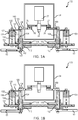
- contactor 54 may comprise a solenoid 22 having a plunger 24 moveable between a first position, as illustrated in FIG. 1A , wherein electrical leads 108, 109 are electrically coupled and a second position, as illustrated in FIG. 1B , wherein electrical leads 108, 109 are electrically decoupled.
- plunger In the first position, plunger may be positioned such that moveable members (also referred to herein as electrical contacting pads) 26, 27 are in contact with electrical contacting pads 28, 29, respectively, such that current (illustrated by the solid line arrows in FIG. 1A ) flows between electrical lead 108 and electrical lead 109.
- plunger 24 In the second position, illustrated in FIG. 1B , plunger 24 may be positioned such that electrical contacting pads 26, 27 are not in contact with electrical contacting pads 28, 29, respectively, such that current is prohibited from flowing between electrical lead 108 and electrical lead 109, (i.e., an open circuit).
- the posts 104, 106 are electrically and thermally coupled to the bus bars 50.
- the contactor arrangement 100 additionally includes a panel 110 including multiple holes 112 through which the posts 104, 106 extend.
- the posts 104, 106 are electrically insulated from panel 110.
- An insulator 114 may be positioned between post 104 and panel 110 to electrically insulate panel 110 from post 104.
- An insulator 116 may be positioned between post 106 and panel 110 to electrically insulate panel 110 from post 106.
- post 104 and post 106 may be mounted to insulator 114 and insulator 116, respectively.
- post 104 and post 106 may be compressed within insulator 114 and insulator 116, respectively.
- insulator 114 and insulator 116 may be adhered to post 104 and post 106, respectively. In various embodiments, insulator 114 and insulator 116 may be mounted to panel 110. Insulator 114 and insulator 116 may comprise a non-conductive material, such as a polymer, a plastic, or a glass, among others.
- post 104 may comprise an integrated heat sink shunt 120 extending from post 104.
- Post 104 and heat sink shunt 120 may be comprised of a single piece of electrically and thermally conductive material, such as aluminum or copper for example. Stated differently, post 104 and heat sink shunt 120 may be comprised of a monolithic piece of electrically and thermally conductive material.
- post 104 and heat sink shunt 120 may be made from a single billet of material. Post 104 and heat sink shunt 120 may be manufactured using additive manufacturing methods or subtractive manufacturing methods. During operation, heat is generated between the stationary electrical contacting pads 28, 29 and mobile electrical contacting pads 26, 27, respectively. This heating is caused due to contact electrical resistances between the stationary and mobile contacting pads.
- Heat from these contacting pads are conducted to the stationary pads (i.e., electrical contacting pads 28, 29), to the posts (i.e., posts 104, 106) and into the heat sink shunts (i.e., heat sink shunt 120).
- Heat (illustrated by the dashed line arrows in FIG. 1A ) may be transferred from solenoid 22, through electrical lead 108, into post 104. This heat may be transferred from post 104 into heat sink shunt 120, through heat sink 130, and into panel 110. This heat may be transferred from post 104 into bus bar 50.
- Manufacturing heat sink shunt 120 and post 104 as a monolithic piece may prevent heat from being generated at a joint between heat sink shunt 120 and post 104, for example if heat sink shunt 120 and post 104 were manufactured as separate pieces.
- a fastener 126 may extend through electrical lead 108 and first end 140 of post 104, whereby electrical lead 108 is coupled to post 104.
- a fastener 127 may extend through electrical bus bar 50 and second end 142 of post 104, whereby post 104 is coupled to bus bar 50.
- heat sink shunt 120 may extend substantially orthogonally away from post 104, wherein the term "substantially” in this regard means within five degrees ( ⁇ 5°).
- heat sink shunt 120 and post 104 may comprise an "L" shape.
- Heat sink shunt 120 may comprise a contacting surface 122 configured to contact a heat sink 130. Heat sink shunt 120 may be located at first end 140.
- heat sink 130 may be mounted to heat sink shunt 120. Heat sink 130 may be mounted to panel 110. Heat sink 130 may extend between heat sink shunt 120 and panel 110. The overall size, shape, and material configuration of the heat sink 130 disclosed herein may be generally determined by the amount of heat to be dissipated.
- heat sink 130 may comprise a first portion 132 comprising a first material being electrically non-conductive and thermally conductive, such as aluminum nitride (AlN).
- heat sink 130 may comprise a second portion 134 comprising a second material being thermally conductive, such as copper or aluminum.
- a fastener 128 may extend through heat sink shunt 120 and heat sink 130, whereby heat sink 130 is coupled to heat sink shunt 120.
- a second heat sink 131 may be coupled between panel 110 and post 106, in a similar manner as heat sink 130, panel 110, and post 104.
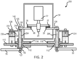
- FIG. 2 elements with like element numbering, as depicted in FIG. 1A , are intended to be the same and will not necessarily be repeated for the sake of clarity.
- a contactor arrangement 200 for connecting electrical contactor 54 to at least one bus bar 50, is illustrated.
- Contactor arrangement 200 may be similar to contactor arrangement 100 of FIG. 1A , except that heat sink shunt 220 extends from post 204 at a location between first end 140 and second end 142, instead of extending from post 204 at first end 140.
- a step 244 may be defined by heat sink shunt 220 and post 204.
- heat sink shunt 220 and post 204 may comprise a "T" shape.
- Post 206 may be similar to post 204.
- Heat sink 230 and heat sink 231 may be similar to heat sink 130 of FIG. 1A .
- post 104 of FIG. 1A may be similar to post 304.
- Post 304 may comprise a rectangular body 312 extending between a first end 340 and a second end 342.
- Heat sink shunt 320 may extend from rectangular body 312.
- Heat sink shunt 320 may comprise a tab 322.
- a first opening 314 may be disposed in rectangular body 312 at first end 340.
- a second opening 316 may be disposed in heat sink shunt 320.
- First opening 314 and second opening 316 may be configured to receive fasteners, such as fastener 126 and fastener 128, respectively, for example, with momentary reference to FIG. 1A .
- a smooth, seamless surface 324 may define first end 340.
- Surface 324 may be defined by rectangular body 312 and heat sink shunt 320.
- Surface 324 may be a planar surface.
- post 304 may be plated with an electrically and thermally conductive material (also referred to herein as a second electrically and thermally conductive material), such as nickel, silver, or copper for example. Stated differently, post 304 may comprise a conductive material coating 371.
- an electrically and thermally conductive material also referred to herein as a second electrically and thermally conductive material
- post 304 may comprise a conductive material coating 371.
- post 204 of FIG. 2 may be similar to post 404.
- Post 404 may comprise a rectangular body 412 extending between a first end 440 and a second end 442.
- Heat sink shunt 420 may extend from rectangular body 412.
- Heat sink shunt 420 may comprise a tab 422.
- a first opening 414 may be disposed in rectangular body 412 at first end 440.
- a second opening 416 may be disposed in heat sink shunt 420.
- First opening 414 and second opening 416 may be configured to receive fasteners, such as fastener 126 and fastener 128, respectively, for example, with momentary reference to FIG. 2 .
- a stepped surface 424 may be defined by rectangular body 412 and heat sink shunt 420.
- post 404 may be plated with an electrically and thermally conductive material, such as nickel or silver for example. Stated differently, post 404 may comprise a conductive material coating 471.
- Contactor post arrangement 500 may include an insulator 515 having a first plurality of apertures 562, such as three apertures 562 for example, disposed on a first side 571 of insulator 515 and a second plurality of apertures 564, such as three apertures 564 for example, disposed on a second side 572 of insulator 515.
- a first plurality of contactor posts 504 may extend through the first plurality of apertures 562.
- a second plurality of contactor posts 506 may extend through the second plurality of apertures 564.
- contactor post arrangement 500 may be symmetric.
- each contactor post 504 may comprise an opening (also referred to herein as a third opening) 566 configured to receive a fastener, such as fastener 127 for example, for coupling contactor posts 504 to a bus bar, such as bus bar 50 for example, with momentary reference to FIG. 1A .
- a fastener such as fastener 127 for example
- FIG. 6A, FIG. 6B, and FIG. 6C elements with like element numbering, as depicted in FIG. 5A, FIG. 5B, and FIG. 5C , are intended to be the same and will not necessarily be repeated for the sake of clarity.
- contactor post arrangement 600 may be similar to contactor post arrangement 500 of FIG. 5A , except that contactor post arrangement 600 includes a two-piece insulator, instead of a one-piece insulator as illustrated in FIG. 5A .
- contactor post arrangement 600 may include a first insulator 514 having a first plurality of apertures 562, such as three apertures 562 for example.
- contactor post arrangement 600 may include a second insulator 516 having a second plurality of apertures 564, such as three apertures 564 for example.
- a first plurality of contactor posts 504 may extend through the first plurality of apertures 562.
- a second plurality of contactor posts 506 may extend through the second plurality of apertures 564.
- contactor post arrangement 600 may be symmetric.
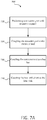
- Method 700 includes positioning a contactor post with respect to a panel (step 710).
- Method 700 includes coupling the contactor post to an electrical lead (step 720).
- Method 700 includes coupling the contactor post to a bus bar (step 730).
- Method 700 includes coupling the heat sink shunt to a heat sink (step 740).
- step 710 may include positioning contactor post 104 with respect to panel 110.
- step 710 may include positioning contactor post 104 to extend through panel 110.
- Step 720 may include coupling contactor post 104 to electrical lead 108.
- Step 720 may include positioning fastener 126 to extend through electrical lead 108 and into contactor post 104.
- fastener 126 may comprise a screw or bolt.
- Step 730 may include coupling contactor post 104 to bus bar 50.
- Step 740 may include coupling heat sink shunt 120 to heat sink 130.
- Step 740 may include positioning fastener 128 to extend through heat sink shunt 120 and into heat sink 130.
- fastener 128 may comprise a screw or bolt.
- a method 702 for installing a contactor arrangement is illustrated, in accordance with various embodiments.
- Method 702 may be similar to method 700 except that method 700 further includes positioning a contactor post to extend through an insulator (step 705).
- a contactor post arrangement 600 may comprise a plurality of contactor posts (e.g., contactor posts 504, 506) installed onto an insulator. However, a plurality of contactor posts may not yet be installed onto the insulator.
- step 705 may include positioning contactor post 504 to extend through insulator 515.
- step 705 may include positioning contactor post 506 to extend through insulator 515.
- references to "one embodiment”, “an embodiment”, “various embodiments”, etc. indicate that the embodiment described may include a particular feature, structure, or characteristic, but every embodiment may not necessarily include the particular feature, structure, or characteristic. Moreover, such phrases are not necessarily referring to the same embodiment. Further, when a particular feature, structure, or characteristic is described in connection with an embodiment, it is submitted that it is within the knowledge of one skilled in the art to affect such feature, structure, or characteristic in connection with other embodiments whether or not explicitly described. After reading the description, it will be apparent to one skilled in the relevant art(s) how to implement the disclosure in alternative embodiments.
Landscapes
- Physics & Mathematics (AREA)
- Electromagnetism (AREA)
- Engineering & Computer Science (AREA)
- Manufacturing & Machinery (AREA)
- Cooling Or The Like Of Electrical Apparatus (AREA)
- Cooling Or The Like Of Semiconductors Or Solid State Devices (AREA)
Abstract
Description
- The present disclosure relates to electrical contactors and, more particularly, to a heat sink for dissipating heat generated by an electrical contactor connected to a mounting panel.
- Contactor assemblies are used in electrical applications, such as aircraft power distribution systems, where power and current flow control of a multi-phase power distribution system is desired. A contactor arrangement typically has a panel on which several electrical contactors are mounted. Known mounting assemblies used to mount electrical contactors to the panels are constructed of thermally and electrically resistive materials, such as plastics or FR-4 for example.
- Each of the contactors is connected to an electrical bus bar, and allows current to flow through the contactor and the corresponding bus bar whenever the contactor is in a closed position. The electrical power and current flow through the contactors is controlled by mechanically actuating a contact plate within the contactor such that, when current flow is desired to pass through the contactor, the contact plate is pushed into electrical contact with two leads and forms an electrical path coupling the leads, thereby allowing current to flow through it. Due to the amount of current traveling from the leads to the connector and the contact resistance at the contact points, waste heat is generated at the contact points and should be removed in order to prevent heat buildup. Additional factors such as imperfections in the contact surfaces or other imperfections can add to the amount of waste heat generated.
- A contactor post for an electrical contactor is disclosed, comprising a body comprising an electrically and thermally conductive material, and a heat sink shunt extending from the body and comprising the electrically and thermally conductive material, wherein the body and the heat sink shunt are comprised of a single piece of the electrically and thermally conductive material.
- In various embodiments, the heat sink shunt extends substantially perpendicular from the body.
- In various embodiments, the body extends longitudinally between a first end of the contactor post and a second end of the contactor post.
- In various embodiments, the heat sink shunt extends from the body at the first end.
- In various embodiments, the first end is at least partially defined by a planar surface defined by the body and the heat sink shunt.
- In various embodiments, the contactor post comprises an "L" shape.
- In various embodiments, the heat sink shunt extends from the body at a location between the first end and the second end.
- In various embodiments, the first end is at least partially defined by a stepped surface defined by the body and the heat sink shunt.
- In various embodiments, the contactor post comprises a "T" shape.
- In various embodiments, the contactor post is plated with a second electrically and thermally conductive material.
- An electrical contactor arrangement is disclosed, comprising an insulator defining an aperture, a contactor post extending through the aperture, wherein the contactor post comprises a body comprising an electrically conductive material, and a heat sink shunt extending from the body and comprising the electrically conductive material, wherein the body and the heat sink shunt are comprised of a single piece of the electrically conductive material.
- In various embodiments, the electrical contactor arrangement further comprises a first opening disposed in a first end of the body, and a first fastener extending into the first opening, whereby an electrical lead is coupled to the body.
- In various embodiments, the electrical contactor arrangement further comprises a second opening disposed in the heat sink shunt, and a second fastener extending into the second opening, whereby a heat sink is coupled to the heat sink shunt.
- In various embodiments, the electrical contactor arrangement further comprises a third opening disposed in a second end of the body, and a third fastener extending into the third opening, whereby a bus bar is coupled to the body.
- In various embodiments, the electrical contactor arrangement further comprises a first plurality of apertures disposed on a first side of the insulator, a second plurality of apertures disposed on a second side of the insulator, a first plurality of contactor posts extending through the first plurality of apertures, and a second plurality of contactor posts extending through the second plurality of apertures.
- In various embodiments, the electrical contactor arrangement further comprises an electrical contactor, the electrical lead coupled between the contactor post and the electrical contactor, a panel, an insulator coupled between the panel and the contactor post, the heat sink coupled between the panel and the heat sink shunt, wherein the panel is thermally coupled to the heat sink shunt via the heat sink, and the bus bar coupled to the contactor post.
- In various embodiments, the electrical contactor comprises a moveable member moveable between a first position and a second position.
- In various embodiments, the heat sink shunt is in contact with the heat sink.
- A method for installing a contactor arrangement is disclosed, comprising positioning a contactor post with respect to a panel, wherein the contactor post comprises a body comprising an electrically conductive material and a heat sink shunt extending from the body, coupling a first end of the contactor post to an electrical lead, coupling a second end of the contactor post to a bus bar, and coupling the heat sink shunt to a heat sink.
- In various embodiments, the method further comprises positioning the contactor post to extend through an insulator.
- The foregoing features and elements may be combined in various combinations without exclusivity, unless expressly indicated herein otherwise. These features and elements as well as the operation of the disclosed embodiments will become more apparent in light of the following description and accompanying drawings.
- The subject matter of the present disclosure is particularly pointed out and distinctly claimed in the concluding portion of the specification. A more complete understanding of the present disclosure, however, may best be obtained by referring to the detailed description and claims when considered in connection with the drawing figures, wherein like numerals denote like elements.
-
FIG. 1A is a schematic view of an electrical contactor arrangement with a contactor in a closed position, in accordance with various embodiments; -
FIG. 1B is a schematic view of an electrical contactor arrangement with a contactor in an open position, in accordance with various embodiments; -
FIG. 2 is a schematic view of an electrical contactor arrangement, in accordance with various embodiments; -
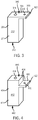
FIG. 3 is an isometric view of an electrical contactor arrangement, in accordance with various embodiments; -
FIG. 4 is an isometric view of an electrical contactor arrangement, in accordance with various embodiments; -
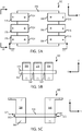
FIG. 5A, FIG. 5B, and FIG. 5C are top, side, and front views, respectively, of a one-piece insulator arrangement for a plurality of contactor posts, in accordance with various embodiments; -
FIG. 6A, FIG. 6B, and FIG. 6C are top, side, and front views, respectively, of a two-piece insulator arrangement for a plurality of contactor posts, in accordance with various embodiments; and -
FIG. 7A andFIG. 7B are flow charts illustrating a method of installing an electrical contactor arrangement, in accordance with various embodiments. - The detailed description of exemplary embodiments herein makes reference to the accompanying drawings, which show exemplary embodiments by way of illustration and their best mode. While these exemplary embodiments are described in sufficient detail to enable those skilled in the art to practice the inventions, it should be understood that other embodiments may be realized and that logical, chemical and mechanical changes may be made without departing from the scope of the inventions. Thus, the detailed description herein is presented for purposes of illustration only and not of limitation. For example, the steps recited in any of the method or process descriptions may be executed in any order and are not necessarily limited to the order presented. Furthermore, any reference to singular includes plural embodiments, and any reference to more than one component or step may include a singular embodiment or step. Also, any reference to attached, fixed, connected or the like may include permanent, removable, temporary, partial, full and/or any other possible attachment option. Additionally, any reference to without contact (or similar phrases) may also include reduced contact or minimal contact.
- Contactors may be cooled by heat sinks for enhanced cooling. Bolted joints may be formed between various members of a contactor arrangement. Joints may add to the resistance of an electrical current flow path, causing additional heat to be generated. In this regard, a contactor arrangement, as disclosed herein, include a contactor post having an integrally formed heat sink shunt. The contactor post having the integrally formed heat sink shunt may tend to reduce heat generation in response to electrical current while tending to increase heat transfer to a heat sink, enhancing cooling of the arrangement.
- Referring now to
FIG. 1A and FIG. 1B , acontactor arrangement 100, for connecting anelectrical contactor 54 to at least onebus bar 50, is illustrated. Thecontactor arrangement 100 has at least onepost 104 for connecting acontactor 54 to a first side of abus bar 50 and at least onepost 106 for connecting thecontactor 54 to a second side of abus bar 50. Theelectrical contactor 54 connects to theposts contactor arrangement 100 via a set ofelectrical leads - For example,
contactor 54 may comprise asolenoid 22 having aplunger 24 moveable between a first position, as illustrated inFIG. 1A , whereinelectrical leads FIG. 1B , whereinelectrical leads pads FIG. 1A ) flows betweenelectrical lead 108 andelectrical lead 109. In the second position, illustrated inFIG. 1B ,plunger 24 may be positioned such that electrical contactingpads pads electrical lead 108 andelectrical lead 109, (i.e., an open circuit). - The
posts contactor arrangement 100 additionally includes apanel 110 includingmultiple holes 112 through which theposts posts panel 110. Aninsulator 114 may be positioned betweenpost 104 andpanel 110 to electrically insulatepanel 110 frompost 104. Aninsulator 116 may be positioned betweenpost 106 andpanel 110 to electrically insulatepanel 110 frompost 106. In various embodiments, post 104 and post 106 may be mounted toinsulator 114 andinsulator 116, respectively. In various embodiments, post 104 and post 106 may be compressed withininsulator 114 andinsulator 116, respectively. In various embodiments,insulator 114 andinsulator 116 may be adhered to post 104 and post 106, respectively. In various embodiments,insulator 114 andinsulator 116 may be mounted topanel 110.Insulator 114 andinsulator 116 may comprise a non-conductive material, such as a polymer, a plastic, or a glass, among others. - In various embodiments, post 104 may comprise an integrated
heat sink shunt 120 extending frompost 104.Post 104 andheat sink shunt 120 may be comprised of a single piece of electrically and thermally conductive material, such as aluminum or copper for example. Stated differently, post 104 andheat sink shunt 120 may be comprised of a monolithic piece of electrically and thermally conductive material. In various embodiments, post 104 andheat sink shunt 120 may be made from a single billet of material.Post 104 andheat sink shunt 120 may be manufactured using additive manufacturing methods or subtractive manufacturing methods. During operation, heat is generated between the stationary electrical contactingpads pads pads 28, 29), to the posts (i.e., posts 104, 106) and into the heat sink shunts (i.e., heat sink shunt 120). In addition, there is heat generated insolenoid 22. Heat (illustrated by the dashed line arrows inFIG. 1A ) may be transferred fromsolenoid 22, throughelectrical lead 108, intopost 104. This heat may be transferred frompost 104 intoheat sink shunt 120, throughheat sink 130, and intopanel 110. This heat may be transferred frompost 104 intobus bar 50. Manufacturingheat sink shunt 120 and post 104 as a monolithic piece may prevent heat from being generated at a joint betweenheat sink shunt 120 and post 104, for example ifheat sink shunt 120 and post 104 were manufactured as separate pieces. - In various embodiments, a
fastener 126 may extend throughelectrical lead 108 andfirst end 140 ofpost 104, wherebyelectrical lead 108 is coupled to post 104. Afastener 127 may extend throughelectrical bus bar 50 andsecond end 142 ofpost 104, wherebypost 104 is coupled tobus bar 50. - In various embodiments,
heat sink shunt 120 may extend substantially orthogonally away frompost 104, wherein the term "substantially" in this regard means within five degrees (±5°). In various embodiments,heat sink shunt 120 and post 104 may comprise an "L" shape.Heat sink shunt 120 may comprise a contactingsurface 122 configured to contact aheat sink 130.Heat sink shunt 120 may be located atfirst end 140. - In various embodiments,
heat sink 130 may be mounted toheat sink shunt 120.Heat sink 130 may be mounted topanel 110.Heat sink 130 may extend betweenheat sink shunt 120 andpanel 110. The overall size, shape, and material configuration of theheat sink 130 disclosed herein may be generally determined by the amount of heat to be dissipated. In various embodiments,heat sink 130 may comprise afirst portion 132 comprising a first material being electrically non-conductive and thermally conductive, such as aluminum nitride (AlN). In various embodiments,heat sink 130 may comprise asecond portion 134 comprising a second material being thermally conductive, such as copper or aluminum. Afastener 128 may extend throughheat sink shunt 120 andheat sink 130, wherebyheat sink 130 is coupled toheat sink shunt 120. - In various embodiments, a
second heat sink 131 may be coupled betweenpanel 110 and post 106, in a similar manner asheat sink 130,panel 110, and post 104. - With respect to
FIG. 2 , elements with like element numbering, as depicted inFIG. 1A , are intended to be the same and will not necessarily be repeated for the sake of clarity. - With reference to
FIG. 2 , acontactor arrangement 200, for connectingelectrical contactor 54 to at least onebus bar 50, is illustrated.Contactor arrangement 200 may be similar tocontactor arrangement 100 ofFIG. 1A , except thatheat sink shunt 220 extends frompost 204 at a location betweenfirst end 140 andsecond end 142, instead of extending frompost 204 atfirst end 140. In this regard, astep 244 may be defined byheat sink shunt 220 andpost 204. In this regard,heat sink shunt 220 and post 204 may comprise a "T" shape.Post 206 may be similar to post 204.Heat sink 230 andheat sink 231 may be similar toheat sink 130 ofFIG. 1A . - With reference to
FIG. 3 , an isometric view of apost 304 having an integratedheat sink shunt 320 is illustrated, in accordance with various embodiments. In various embodiments, post 104 ofFIG. 1A may be similar to post 304.Post 304 may comprise arectangular body 312 extending between afirst end 340 and asecond end 342.Heat sink shunt 320 may extend fromrectangular body 312.Heat sink shunt 320 may comprise atab 322. Afirst opening 314 may be disposed inrectangular body 312 atfirst end 340. Asecond opening 316 may be disposed inheat sink shunt 320.First opening 314 andsecond opening 316 may be configured to receive fasteners, such asfastener 126 andfastener 128, respectively, for example, with momentary reference toFIG. 1A . A smooth,seamless surface 324 may definefirst end 340.Surface 324 may be defined byrectangular body 312 andheat sink shunt 320.Surface 324 may be a planar surface. - In various embodiments, post 304 may be plated with an electrically and thermally conductive material (also referred to herein as a second electrically and thermally conductive material), such as nickel, silver, or copper for example. Stated differently, post 304 may comprise a
conductive material coating 371. - With reference to
FIG. 4 , an isometric view of apost 404 having an integratedheat sink shunt 420 is illustrated, in accordance with various embodiments. In various embodiments, post 204 ofFIG. 2 may be similar to post 404.Post 404 may comprise arectangular body 412 extending between afirst end 440 and asecond end 442.Heat sink shunt 420 may extend fromrectangular body 412.Heat sink shunt 420 may comprise atab 422. Afirst opening 414 may be disposed inrectangular body 412 atfirst end 440. Asecond opening 416 may be disposed inheat sink shunt 420.First opening 414 andsecond opening 416 may be configured to receive fasteners, such asfastener 126 andfastener 128, respectively, for example, with momentary reference toFIG. 2 . A steppedsurface 424 may be defined byrectangular body 412 andheat sink shunt 420. - In various embodiments, post 404 may be plated with an electrically and thermally conductive material, such as nickel or silver for example. Stated differently, post 404 may comprise a
conductive material coating 471. - With combined reference to
FIG. 5A, FIG. 5B, and FIG. 5C , acontactor post arrangement 500 is illustrated, in accordance with various embodiments.Contactor post arrangement 500 may include aninsulator 515 having a first plurality ofapertures 562, such as threeapertures 562 for example, disposed on afirst side 571 ofinsulator 515 and a second plurality ofapertures 564, such as threeapertures 564 for example, disposed on asecond side 572 ofinsulator 515. A first plurality ofcontactor posts 504 may extend through the first plurality ofapertures 562. A second plurality ofcontactor posts 506 may extend through the second plurality ofapertures 564. In various embodiments,contactor post arrangement 500 may be symmetric. - In various embodiments, each
contactor post 504 may comprise an opening (also referred to herein as a third opening) 566 configured to receive a fastener, such asfastener 127 for example, forcoupling contactor posts 504 to a bus bar, such asbus bar 50 for example, with momentary reference toFIG. 1A . - With respect to
FIG. 6A, FIG. 6B, and FIG. 6C , elements with like element numbering, as depicted inFIG. 5A, FIG. 5B, and FIG. 5C , are intended to be the same and will not necessarily be repeated for the sake of clarity. - With combined reference to
FIG. 6A, FIG. 6B, and FIG. 6C , acontactor post arrangement 600 is illustrated, in accordance with various embodiments.Contactor post arrangement 600 may be similar tocontactor post arrangement 500 ofFIG. 5A , except thatcontactor post arrangement 600 includes a two-piece insulator, instead of a one-piece insulator as illustrated inFIG. 5A . In this regard,contactor post arrangement 600 may include afirst insulator 514 having a first plurality ofapertures 562, such as threeapertures 562 for example.Contactor post arrangement 600 may include asecond insulator 516 having a second plurality ofapertures 564, such as threeapertures 564 for example. A first plurality ofcontactor posts 504 may extend through the first plurality ofapertures 562. A second plurality ofcontactor posts 506 may extend through the second plurality ofapertures 564. In various embodiments,contactor post arrangement 600 may be symmetric. - With reference to
FIG. 7A , amethod 700 for installing a contactor arrangement, is illustrated, in accordance with various embodiments.Method 700 includes positioning a contactor post with respect to a panel (step 710).Method 700 includes coupling the contactor post to an electrical lead (step 720).Method 700 includes coupling the contactor post to a bus bar (step 730).Method 700 includes coupling the heat sink shunt to a heat sink (step 740). - With combined reference to
FIG. 7A andFIG. 1A , step 710 may include positioning contactor post 104 with respect topanel 110. For example, step 710 may include positioning contactor post 104 to extend throughpanel 110. Step 720 may include coupling contactor post 104 toelectrical lead 108. Step 720 may includepositioning fastener 126 to extend throughelectrical lead 108 and intocontactor post 104. In various embodiments,fastener 126 may comprise a screw or bolt. Step 730 may include coupling contactor post 104 tobus bar 50. Step 740 may include couplingheat sink shunt 120 toheat sink 130. Step 740 may includepositioning fastener 128 to extend throughheat sink shunt 120 and intoheat sink 130. In various embodiments,fastener 128 may comprise a screw or bolt. - With reference to
FIG. 7B , amethod 702 for installing a contactor arrangement, is illustrated, in accordance with various embodiments.Method 702 may be similar tomethod 700 except thatmethod 700 further includes positioning a contactor post to extend through an insulator (step 705). With combined reference toFIG. 7B andFIG. 5C , acontactor post arrangement 600 may comprise a plurality of contactor posts (e.g., contactor posts 504, 506) installed onto an insulator. However, a plurality of contactor posts may not yet be installed onto the insulator. In this regard,step 705 may include positioning contactor post 504 to extend throughinsulator 515. In various embodiments,step 705 may include positioning contactor post 506 to extend throughinsulator 515. - Benefits, other advantages, and solutions to problems have been described herein with regard to specific embodiments. Furthermore, the connecting lines shown in the various figures contained herein are intended to represent exemplary functional relationships and/or physical couplings between the various elements. It should be noted that many alternative or additional functional relationships or physical connections may be present in a practical system. However, the benefits, advantages, solutions to problems, and any elements that may cause any benefit, advantage, or solution to occur or become more pronounced are not to be construed as critical, required, or essential features or elements of the inventions. The scope of the inventions is accordingly to be limited by nothing other than the appended claims, in which reference to an element in the singular is not intended to mean "one and only one" unless explicitly so stated, but rather "one or more." Moreover, where a phrase similar to "at least one of A, B, or C" is used in the claims, it is intended that the phrase be interpreted to mean that A alone may be present in an embodiment, B alone may be present in an embodiment, C alone may be present in an embodiment, or that any combination of the elements A, B and C may be present in a single embodiment; for example, A and B, A and C, B and C, or A and B and C. Different cross-hatching is used throughout the figures to denote different parts but not necessarily to denote the same or different materials.
- Systems, methods and apparatus are provided herein. In the detailed description herein, references to "one embodiment", "an embodiment", "various embodiments", etc., indicate that the embodiment described may include a particular feature, structure, or characteristic, but every embodiment may not necessarily include the particular feature, structure, or characteristic. Moreover, such phrases are not necessarily referring to the same embodiment. Further, when a particular feature, structure, or characteristic is described in connection with an embodiment, it is submitted that it is within the knowledge of one skilled in the art to affect such feature, structure, or characteristic in connection with other embodiments whether or not explicitly described. After reading the description, it will be apparent to one skilled in the relevant art(s) how to implement the disclosure in alternative embodiments.
- Furthermore, no element, component, or method step in the present disclosure is intended to be dedicated to the public regardless of whether the element, component, or method step is explicitly recited in the claims. As used herein, the terms "comprises," "comprising," or any other variation thereof, are intended to cover a non-exclusive inclusion, such that a process, method, article, or apparatus that comprises a list of elements does not include only those elements but may include other elements not expressly listed or inherent to such process, method, article, or apparatus.
Claims (15)
- A contactor post (104) for an electrical contactor, comprising:a body comprising an electrically and thermally conductive material; anda heat sink shunt (120) extending from the body and comprising the electrically and thermally conductive material,wherein the body and the heat sink shunt (120) are comprised of a monolithic piece of the electrically and thermally conductive material.
- The contactor post of claim 1, wherein the heat sink shunt (120) extends substantially perpendicular from the body.
- The contactor post of claim 1, wherein the body extends longitudinally between a first end of the contactor post and a second end of the contactor post.
- The contactor post of claim 3, wherein the heat sink shunt (120) extends from the body at the first end.
- The contactor post of claim 4, wherein the first end is at least partially defined by a planar surface defined by the body and the heat sink shunt (120), and preferably wherein the contactor post (104) comprises an "L" shape.
- The contactor post of claim 3, wherein the heat sink shunt (120) extends from the body at a location between the first end and the second end, and preferably wherein the first end is at least partially defined by a stepped surface defined by the body and the heat sink shunt, and more preferably wherein the contactor post (104) comprises a "T" shape.
- The contactor post of any preceding claim, wherein the contactor post (104) is plated with a second electrically and thermally conductive material.
- An electrical contactor arrangement, comprising:an insulator (114) defining an aperture;a contactor post (104) extending through the aperture, wherein the contactor post comprises:a body comprising an electrically conductive material; anda heat sink shunt (120) extending from the body and comprising the electrically conductive material, wherein the body and the heat sink shunt (120) are comprised of a single piece of the electrically conductive material.
- The electrical contactor arrangement of claim 8, further comprising:a first opening disposed in a first end of the body; anda first fastener (127) extending into the first opening, whereby an electrical lead is coupled to the body.
- The electrical contactor arrangement of claim 9, further comprising:a second opening disposed in the heat sink shunt; anda second fastener (128) extending into the second opening, whereby a heat sink (130) is coupled to the heat sink shunt (120).
- The electrical contactor arrangement of claim 10, further comprising:a third opening disposed in a second end of the body; anda third fastener (126) extending into the third opening, whereby a bus bar (50) is coupled to the body.
- The electrical contactor arrangement of claim 8, further comprising:a first plurality of apertures (562) disposed on a first side of the insulator;a second plurality of apertures (564) disposed on a second side of the insulator;a first plurality of contactor posts (504) extending through the first plurality of apertures; anda second plurality of contactor posts (506) extending through the second plurality of apertures; and preferablyfurther comprising:an electrical contactor (54);the electrical lead (108) coupled between the contactor post and the electrical contactor;a panel (110);the insulator (114) coupled between the panel (110) and the contactor post (104);the heat sink (130) coupled between the panel and the heat sink shunt, wherein the panel is thermally coupled to the heat sink shunt via the heat sink; andthe bus bar (50) coupled to the contactor post (104).
- The electrical contactor arrangement of claim 12, wherein the electrical contactor (54) comprises a moveable member moveable between a first position and a second position; or
wherein the heat sink shunt (120) is in contact with the heat sink (130). - A method for installing a contactor arrangement, comprising:positioning a contactor post with respect to a panel, wherein the contactor post comprises a body comprising an electrically conductive material and a heat sink shunt extending from the body;coupling a first end of the contactor post to an electrical lead;coupling a second end of the contactor post to a bus bar; andcoupling the heat sink shunt to a heat sink.
- The method of claim 14, further comprising positioning the contactor post to extend through an insulator.
Applications Claiming Priority (1)
| Application Number | Priority Date | Filing Date | Title |
|---|---|---|---|
| US15/946,563 US10825630B2 (en) | 2018-04-05 | 2018-04-05 | Integrated mounting post and heat sink for contactor arrangement in power distribution system |
Publications (1)
| Publication Number | Publication Date |
|---|---|
| EP3550584A1 true EP3550584A1 (en) | 2019-10-09 |
Family
ID=65717761
Family Applications (1)
| Application Number | Title | Priority Date | Filing Date |
|---|---|---|---|
| EP19160752.2A Withdrawn EP3550584A1 (en) | 2018-04-05 | 2019-03-05 | Integrated mounting post and heat sink for contactor arrangement in power distribution system |
Country Status (2)
| Country | Link |
|---|---|
| US (1) | US10825630B2 (en) |
| EP (1) | EP3550584A1 (en) |
Families Citing this family (3)
| Publication number | Priority date | Publication date | Assignee | Title |
|---|---|---|---|---|
| US11547024B2 (en) * | 2019-10-15 | 2023-01-03 | Lear Corporation | Electrical assembly |
| US10930460B2 (en) * | 2019-02-14 | 2021-02-23 | Song Chuan Precision Co., Ltd. | Relay structure with heat dissipation function |
| JP7718221B2 (en) * | 2021-10-19 | 2025-08-05 | オムロン株式会社 | electromagnetic relay |
Citations (3)
| Publication number | Priority date | Publication date | Assignee | Title |
|---|---|---|---|---|
| EP3264436A1 (en) * | 2016-06-29 | 2018-01-03 | Hamilton Sundstrand Corporation | Contactor in power distribution assembly |
| EP3270396A1 (en) * | 2016-07-12 | 2018-01-17 | Hamilton Sundstrand Corporation | Mounting arrangements for electrical contactors |
| EP3270402A1 (en) * | 2016-07-11 | 2018-01-17 | Hamilton Sundstrand Corporation | Electrical contactor and panel assemblies |
Family Cites Families (5)
| Publication number | Priority date | Publication date | Assignee | Title |
|---|---|---|---|---|
| US7837496B1 (en) * | 2009-11-17 | 2010-11-23 | Hamilton Sundstrand Corporation | Contactor mounting assembly with improved thermal characteristics |
| US9142364B2 (en) * | 2012-06-29 | 2015-09-22 | Hamilton Sundstrand Corporation | Contactor mounting panel with improved thermal characteristics |
| US9153946B2 (en) * | 2012-09-25 | 2015-10-06 | Hamilton Sundstrand Corporation | Electrical contactor arrangement with thermal management |
| US9137925B2 (en) | 2013-05-08 | 2015-09-15 | Hamilton Sundstrand Corporation | Heat sink for contactor in power distribution assembly |
| US9531170B2 (en) * | 2014-07-22 | 2016-12-27 | Hamilton Sundstrand Corporation | Interconnects for electrical power distribution systems |
-
2018
- 2018-04-05 US US15/946,563 patent/US10825630B2/en active Active
-
2019
- 2019-03-05 EP EP19160752.2A patent/EP3550584A1/en not_active Withdrawn
Patent Citations (3)
| Publication number | Priority date | Publication date | Assignee | Title |
|---|---|---|---|---|
| EP3264436A1 (en) * | 2016-06-29 | 2018-01-03 | Hamilton Sundstrand Corporation | Contactor in power distribution assembly |
| EP3270402A1 (en) * | 2016-07-11 | 2018-01-17 | Hamilton Sundstrand Corporation | Electrical contactor and panel assemblies |
| EP3270396A1 (en) * | 2016-07-12 | 2018-01-17 | Hamilton Sundstrand Corporation | Mounting arrangements for electrical contactors |
Also Published As
| Publication number | Publication date |
|---|---|
| US10825630B2 (en) | 2020-11-03 |
| US20190311870A1 (en) | 2019-10-10 |
Similar Documents
| Publication | Publication Date | Title |
|---|---|---|
| US7837496B1 (en) | Contactor mounting assembly with improved thermal characteristics | |
| US9142364B2 (en) | Contactor mounting panel with improved thermal characteristics | |
| US6786749B2 (en) | Universal connector for securing bus bars to electrical equipment | |
| US9991655B2 (en) | Contactor in power distribution assembly | |
| US9137925B2 (en) | Heat sink for contactor in power distribution assembly | |
| EP3319100B1 (en) | Integrated panel level liquid cooling for bus bars | |
| US10825630B2 (en) | Integrated mounting post and heat sink for contactor arrangement in power distribution system | |
| US20170094790A1 (en) | Circuit Arrangement for Vehicles and Use of a Circuit Arrangement | |
| JP2019153583A (en) | Method and system for cooling battery-integrated power electronics system | |
| CN105990753A (en) | Fixing element for connecting printed circuit board and busbar, and power distributor having the same | |
| CN112020280A (en) | Array surface power module suitable for phased array radar | |
| US20120152706A1 (en) | Electrical system, and circuit protection module and electrical switching apparatus therefor | |
| US8514552B2 (en) | Electrical system and matrix assembly therefor | |
| EP3526805B1 (en) | Fuses with integrated metals | |
| US9918406B2 (en) | Mounting arrangements for electrical contactors | |
| EP3673507B1 (en) | Energy storage assembly, and vehicle comprising an energy storage assembly | |
| EP2817816B1 (en) | Circuit breaker heater-bimetal assembly, heater-bimetal apparatus, and assembly methods thereof | |
| US20240087981A1 (en) | Heat sink for a semiconductor switching device, and semiconductor switching device | |
| US10614983B2 (en) | Switching element for electrical energy distribution board and electrical energy distribution box fitted with such a switching element | |
| US5044966A (en) | Electrical panel for physically supporting and electrically connecting electrical components | |
| US20010043014A1 (en) | Power distribution device comprising bars applied to a plate | |
| KR20180134282A (en) | High current circuit board | |
| US9444230B2 (en) | Power distribution assembly and header assembly therefor | |
| JPH11312453A (en) | High current fuse for automobile |
Legal Events
| Date | Code | Title | Description |
|---|---|---|---|
| PUAI | Public reference made under article 153(3) epc to a published international application that has entered the european phase |
Free format text: ORIGINAL CODE: 0009012 |
|
| STAA | Information on the status of an ep patent application or granted ep patent |
Free format text: STATUS: THE APPLICATION HAS BEEN PUBLISHED |
|
| AK | Designated contracting states |
Kind code of ref document: A1 Designated state(s): AL AT BE BG CH CY CZ DE DK EE ES FI FR GB GR HR HU IE IS IT LI LT LU LV MC MK MT NL NO PL PT RO RS SE SI SK SM TR |
|
| AX | Request for extension of the european patent |
Extension state: BA ME |
|
| STAA | Information on the status of an ep patent application or granted ep patent |
Free format text: STATUS: REQUEST FOR EXAMINATION WAS MADE |
|
| 17P | Request for examination filed |
Effective date: 20191216 |
|
| RBV | Designated contracting states (corrected) |
Designated state(s): AL AT BE BG CH CY CZ DE DK EE ES FI FR GB GR HR HU IE IS IT LI LT LU LV MC MK MT NL NO PL PT RO RS SE SI SK SM TR |
|
| STAA | Information on the status of an ep patent application or granted ep patent |
Free format text: STATUS: EXAMINATION IS IN PROGRESS |
|
| 17Q | First examination report despatched |
Effective date: 20200605 |
|
| STAA | Information on the status of an ep patent application or granted ep patent |
Free format text: STATUS: THE APPLICATION HAS BEEN WITHDRAWN |
|
| 18W | Application withdrawn |
Effective date: 20230111 |