EP3550512A1 - System, jig, information processing device, information processing method, and program - Google Patents
System, jig, information processing device, information processing method, and program Download PDFInfo
- Publication number
- EP3550512A1 EP3550512A1 EP17879522.5A EP17879522A EP3550512A1 EP 3550512 A1 EP3550512 A1 EP 3550512A1 EP 17879522 A EP17879522 A EP 17879522A EP 3550512 A1 EP3550512 A1 EP 3550512A1
- Authority
- EP
- European Patent Office
- Prior art keywords
- angle
- image
- dictionary data
- object obj
- angle information
- Prior art date
- Legal status (The legal status is an assumption and is not a legal conclusion. Google has not performed a legal analysis and makes no representation as to the accuracy of the status listed.)
- Withdrawn
Links
Images









Classifications
-
- G—PHYSICS
- G06—COMPUTING OR CALCULATING; COUNTING
- G06T—IMAGE DATA PROCESSING OR GENERATION, IN GENERAL
- G06T7/00—Image analysis
- G06T7/70—Determining position or orientation of objects or cameras
- G06T7/73—Determining position or orientation of objects or cameras using feature-based methods
- G06T7/74—Determining position or orientation of objects or cameras using feature-based methods involving reference images or patches
-
- B—PERFORMING OPERATIONS; TRANSPORTING
- B25—HAND TOOLS; PORTABLE POWER-DRIVEN TOOLS; MANIPULATORS
- B25J—MANIPULATORS; CHAMBERS PROVIDED WITH MANIPULATION DEVICES
- B25J19/00—Accessories fitted to manipulators, e.g. for monitoring, for viewing; Safety devices combined with or specially adapted for use in connection with manipulators
- B25J19/02—Sensing devices
- B25J19/04—Viewing devices
-
- B—PERFORMING OPERATIONS; TRANSPORTING
- B25—HAND TOOLS; PORTABLE POWER-DRIVEN TOOLS; MANIPULATORS
- B25J—MANIPULATORS; CHAMBERS PROVIDED WITH MANIPULATION DEVICES
- B25J9/00—Program-controlled manipulators
- B25J9/0009—Constructional details, e.g. manipulator supports, bases
-
- B—PERFORMING OPERATIONS; TRANSPORTING
- B25—HAND TOOLS; PORTABLE POWER-DRIVEN TOOLS; MANIPULATORS
- B25J—MANIPULATORS; CHAMBERS PROVIDED WITH MANIPULATION DEVICES
- B25J9/00—Program-controlled manipulators
- B25J9/0096—Program-controlled manipulators co-operating with a working support, e.g. work-table
-
- B—PERFORMING OPERATIONS; TRANSPORTING
- B25—HAND TOOLS; PORTABLE POWER-DRIVEN TOOLS; MANIPULATORS
- B25J—MANIPULATORS; CHAMBERS PROVIDED WITH MANIPULATION DEVICES
- B25J9/00—Program-controlled manipulators
- B25J9/16—Program controls
- B25J9/1602—Program controls characterised by the control system, structure, architecture
-
- B—PERFORMING OPERATIONS; TRANSPORTING
- B25—HAND TOOLS; PORTABLE POWER-DRIVEN TOOLS; MANIPULATORS
- B25J—MANIPULATORS; CHAMBERS PROVIDED WITH MANIPULATION DEVICES
- B25J9/00—Program-controlled manipulators
- B25J9/16—Program controls
- B25J9/1679—Program controls characterised by the tasks executed
-
- B—PERFORMING OPERATIONS; TRANSPORTING
- B25—HAND TOOLS; PORTABLE POWER-DRIVEN TOOLS; MANIPULATORS
- B25J—MANIPULATORS; CHAMBERS PROVIDED WITH MANIPULATION DEVICES
- B25J9/00—Program-controlled manipulators
- B25J9/16—Program controls
- B25J9/1694—Program controls characterised by use of sensors other than normal servo-feedback from position, speed or acceleration sensors, perception control, multi-sensor controlled systems, sensor fusion
- B25J9/1697—Vision controlled systems
-
- G—PHYSICS
- G06—COMPUTING OR CALCULATING; COUNTING
- G06F—ELECTRIC DIGITAL DATA PROCESSING
- G06F18/00—Pattern recognition
- G06F18/20—Analysing
- G06F18/28—Determining representative reference patterns, e.g. by averaging or distorting; Generating dictionaries
-
- G—PHYSICS
- G06—COMPUTING OR CALCULATING; COUNTING
- G06T—IMAGE DATA PROCESSING OR GENERATION, IN GENERAL
- G06T7/00—Image analysis
- G06T7/60—Analysis of geometric attributes
-
- G—PHYSICS
- G06—COMPUTING OR CALCULATING; COUNTING
- G06V—IMAGE OR VIDEO RECOGNITION OR UNDERSTANDING
- G06V10/00—Arrangements for image or video recognition or understanding
- G06V10/70—Arrangements for image or video recognition or understanding using pattern recognition or machine learning
- G06V10/77—Processing image or video features in feature spaces; using data integration or data reduction, e.g. principal component analysis [PCA] or independent component analysis [ICA] or self-organising maps [SOM]; Blind source separation
- G06V10/772—Determining representative reference patterns, e.g. averaging or distorting patterns; Generating dictionaries
-
- G—PHYSICS
- G06—COMPUTING OR CALCULATING; COUNTING
- G06T—IMAGE DATA PROCESSING OR GENERATION, IN GENERAL
- G06T2207/00—Indexing scheme for image analysis or image enhancement
- G06T2207/10—Image acquisition modality
- G06T2207/10016—Video; Image sequence
-
- G—PHYSICS
- G06—COMPUTING OR CALCULATING; COUNTING
- G06T—IMAGE DATA PROCESSING OR GENERATION, IN GENERAL
- G06T2207/00—Indexing scheme for image analysis or image enhancement
- G06T2207/10—Image acquisition modality
- G06T2207/10024—Color image
Definitions
- the present invention relates to a system, a jig, an information processing apparatus, an information processing method, and a program.
- Image-based object recognition is a general technique in recent years.
- image-based object recognition for example, an amount of features of an image captured by an imaging apparatus is extracted, and the amount of features is matched with an amount of features registered in advance as dictionary data to thereby recognize an object in the image.
- dictionary data needs to be prepared for each angle of the object in order to increase the availability of the object recognition.
- PTL 1 and PTL 2 are examples of a technique for preparing the dictionary data for each angle of the object in the image-based object recognition.
- PTL 1 describes a technique of recognizing an object based on eight images obtained by rotating the object at 45-degree intervals.
- PTL 2 describes a technique of learning a model of an object by recognizing common parts from a large number of images obtained by rotating the object in a horizontal angle direction and a zenith angle direction in five-degree increments or the like.
- the techniques are techniques for recognizing the object in the image, that is, estimating what the object in the image is, and it is not intended to draw out additional information from the image.
- it can be advantageous to provide additional information regarding the object based on the image.
- an object of the present invention is to provide new and improved system, jig, information processing apparatus, information processing method, and program that can estimate an angle of an object based on an image.
- An aspect of the present invention provides a system including one or a plurality of information processing apparatuses that individually or cooperatively realize functions including a first image acquisition function of acquiring a first image of an object, an angle information acquisition function of acquiring angle information indicating an angle of the object in the first image, a dictionary data generation function of generating dictionary data based on the first image and the angle information, a second image acquisition function of acquiring a second image of the object different from the first image, and an angle estimation function of estimating an angle of the object in the second image based on the second image and the dictionary data.
- a jig capable of being attached to a platform device, the platform device including a base portion that rotates about a first axis, a pair of supports fixed at positions symmetric with respect to the first axis on the base portion, a pair of arms connected to the pair of supports, respectively, so as to be pivotable about a second axis orthogonal to the first axis, on an opposite side of the base portion, a holder fixed between edges of the pair of arms, on an opposite side of the pair of supports, and a control unit that sets an angle of the base portion rotating about the first axis and an angle of the pair of arms pivoting about the second axis.
- the jig includes an attachment member capable of being attached to the holder of the platform device, an object holder for attaching the object, and a connecting member that connects the attachment member and the object holder and defines a positional relationship between the attachment member and the object holder such that the object attached to the object holder is positioned near an intersection of the first axis and the second axis when the attachment member is attached to the holder of the platform device.
- yet another aspect of the present invention provides an information processing apparatus including a processor that realizes functions including an image acquisition function of acquiring a plurality of images of an object different from each other, an angle information acquisition function of acquiring angle information common to the plurality of images, the angle information indicating an angle of the object, and a dictionary data generation function of generating dictionary data based on the plurality of images and the angle information common to the plurality of images.
- yet another aspect of the present invention provides an information processing apparatus including a processor that realizes functions including a dictionary data acquisition function of acquiring a first image of an object and dictionary data generated based on angle information indicating an angle of the object in the first image, an image acquisition function of acquiring a second image of the object different from the first image, and an angle estimation function of estimating an angle of the object in the second image based on the second image and the dictionary data.
- yet another aspect of the present invention provides an information processing method including a step of acquiring a plurality of images of an object different from each other, a step of acquiring angle information common to the plurality of images, the angle information indicating an angle of the object, and a step of using a processor to generate dictionary data based on the plurality of images and the angle information common to the plurality of images.
- yet another aspect of the present invention provides an information processing method including a step of acquiring dictionary data generated based on a first image of an object and angle information indicating an angle of the object in the first image, a step of acquiring a second image of the object different from the first image, and a step of using a processor to estimate an angle of the object in the second image based on the second image and the dictionary data.
- yet another aspect of the present invention provides a program for causing a processor to realize functions including an image acquisition function of acquiring a plurality of images of an object different from each other, an angle information acquisition function of acquiring angle information common to the plurality of images, the angle information indicating an angle of the object, and a dictionary data generation function of generating dictionary data based on the plurality of images and the angle information common to the plurality of images.
- yet another aspect of the present invention provides a program for causing a processor to realize functions including a dictionary data acquisition function of acquiring dictionary data generated based on a first image of an object and angle information indicating an angle of the object in the first image, a second image acquisition function of acquiring a second image of the object different from the first image, and an angle estimation function of estimating an angle of the object in the second image based on the second image and the dictionary data.
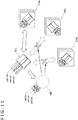
- FIG. 1 is a schematic diagram illustrating a system 10 according to a first embodiment of the present invention.
- the system 10 includes a terminal 100, a database 200, and a robot 300 connected to each other through a network NW.
- a camera 150 and a platform device 160 are connected to the terminal 100.
- the robot 300 includes a camera 310 and a manipulator 320.
- the camera 150 captures an image of an object obj attached to the platform device 160 through a jig 170 described later.
- the terminal 100 acquires the image from the camera 150 and acquires angle information indicating an angle of the object obj from the platform device 160.
- the angle of the object obj is an angle in a three-dimensional space, such as an angle indicated by an amount of rotation about three axes in an orthogonal coordinate system, unless otherwise specifically stated.
- the terminal 100 generates dictionary data based on the acquired image and angle information (as well as identification information of the object obj).
- the generated dictionary data is stored in the database 200.
- the robot 300 uses the camera 310 to capture an image of the object obj while the manipulator 320 holds the object obj.
- the robot 300 recognizes the object obj in the image based on the captured image and the dictionary data acquired from the database 200 and further estimates the angle of the object obj in the image.
- the robot 300 can recognize the object obj and further estimate the angle of the object obj held by the manipulator 320.
- the angle indicates, for example, the degree of rotation of the object obj with respect to a reference posture.
- the robot 300 can, for example, control the manipulator 320 based on the estimation result of the angle to rotate the object obj to thereby set the object obj to a desirable posture.
- the system 10 is useful for, for example, using the robot 300 to automate the work of arranging or organizing commodities.
- the system 10 is also useful for, for example, specifying how to rotate the object obj in order to read information (such as a printed code and a radio frequency identifier (RFID)) arranged at a predetermined part of the object obj.
- RFID radio frequency identifier
- FIG. 2 is a block diagram illustrating a functional configuration of the terminal 100 in the system illustrated in FIG. 1 .
- the terminal 100 includes an image acquisition unit 110, an angle information acquisition unit 120, and a dictionary data generation unit 130.
- the terminal 100 is, for example, a personal computer, a tablet, a smartphone, or the like, and functions of the components are realized by a hardware configuration of an information processing apparatus described later.
- the functions of the image acquisition unit 110, the angle information acquisition unit 120, and the dictionary data generation unit 130 are realized by a processor included in the information processing apparatus.
- Dictionary data 210 generated by the dictionary data generation unit 130 is stored in the database 200 connected to the terminal 100 through the network.
- the function of the database 200 is realized by storage of one or a plurality of information processing apparatuses connected to the network. Note that in a case where the terminal 100 includes a plurality of processors, the plurality of processors may cooperate to realize the functions of the components.
- part or all of the functions realized by the processor of the terminal 100 can also be realized by a server.
- the functions of the components will be described.
- the image acquisition unit 110 acquires the image of the object obj captured by the camera 150.
- the camera 150 is an example of an imaging apparatus that captures an image of an object.
- the camera 150 is, for example, a digital camera including an image sensor, and the image acquisition unit 110 receives image data generated by the camera 150.
- the camera 150 is connected to the terminal 100 through a wired communication interface, such as a universal serial bus (USB), in the illustrated example, the camera 150 may be connected to the terminal 100 through a wireless communication interface, such as Bluetooth (registered trademark), in another example.
- the camera 150 may be built in the terminal 100 and may transmit the image data to the image acquisition unit 110 through a bus.
- the angle information acquisition unit 120 acquires the angle information indicating the angle of the object obj from the platform device 160.
- the angle information acquired by the angle information acquisition unit 120 of the terminal 100 indicates an angle of the object obj on the basis of a coordinate system of the platform device 160.
- the angle information acquisition unit 120 generates the angle information of the object obj, transmits the angle information to the platform device 160, and provides the angle information to the dictionary data generation unit 130 is also included in the case in which "the angle information acquisition unit 120 acquires the angle information.”
- the platform device 160 sets the angle of holding the object obj according to the angle information received from the angle information acquisition unit 120.
- the platform device 160 is an example of holding means for holding the object obj. Similar to the camera 150, the platform device 160 may also be connected to the terminal 100 through a wired communication interface or may be connected to the terminal 100 through a wireless communication interface.
- the angle of the object obj is an angle in the three-dimensional space, such as an angle indicated by an amount of rotation about three axes in the orthogonal coordinate system. Therefore, the angle information acquisition unit 120 expresses the angle information by, for example, the amount of rotation equivalent to the difference between the current posture and the reference posture of the object obj.
- the reference posture is, for example, a posture of the object obj when the platform device 160 is reset.
- the reference posture may be a posture of the object obj when the image acquisition unit 110 first acquires the image of the object obj to generate the dictionary data 210.
- the dictionary data generation unit 130 generates the dictionary data 210 based on the image acquired by the image acquisition unit 110, the identification information of the object obj, and the angle information acquired by the angle information acquisition unit 120.
- the identification information of the object obj may be specified by any means.
- the identification information of the object obj may be specified based on information input to the terminal 100 by the user.
- the identification information of the object obj may also be specified by matching the image acquired by the image acquisition unit 110 with dictionary data separately provided for image-based object recognition.
- the dictionary data generation unit 130 may allocate the identification information to the object obj commonly included in a plurality of images acquired by the image acquisition unit 110.
- the dictionary data generation unit 130 may use an appropriate method used in the image-based object recognition to extract an amount of features from the image and may associate the extracted amount of features with the identification information and the angle information of the object obj.
- the dictionary data generation unit 130 may use the identification information of the object obj classified and labeled by an appropriate method used in the image-based object recognition.
- the dictionary data 210 is generated based on the identification information of the object obj in the description of the present embodiment, the dictionary data 210 may not be generated based on the identification information of the object obj.
- the dictionary data 210 may not include the identification information of the object obj.
- the dictionary data 210 includes the identification information of the object obj as in the present embodiment, a plurality of types of objects obj can be recognized, and then the angles of the objects obj can be further estimated.
- the configuration of the platform device 160 used with the terminal 100 in the system 10 according to the present embodiment and the configuration of the jig 170 for attaching the object obj to the platform device 160 will be further described.
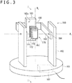
- FIG. 3 is a schematic perspective view illustrating the configuration of the platform device 160 and the jig 170 used in the system illustrated in FIG. 1 .
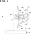
- FIG. 4 is a cross-sectional view taken along line I-I of FIG. 3 .
- the platform device 160 includes a base 161, a pair of supports 162, a pair of arms 163, a pair of pins 164, a holder 165, a beam 166, and a control unit 167.
- the jig 170 includes an attachment member 171, a connecting member 172, an object holder 173, and a background plate 174. Note that the background plate 174 is not illustrated in FIG. 3 .
- each component will be described.
- the base 161 is, for example, a rotary table.
- the base 161 is driven by a motor (not illustrated) controlled by the control unit 167 and rotates about an axis A 1 .
- the axis A 1 is orthogonal to an optical axis (illustrated as an axis A 3 in FIG. 4 ) of the camera 150.
- the pair of supports 162 are fixed on the base 161 at positions symmetric with respect to the axis A 1 . Therefore, the midpoint of the pair of supports 162 substantially coincides with the axis A 1 .
- the pins 164 are used to connect the pair of arms 163 to the pair of supports 162, respectively, on the opposite side of the base 161.
- the pins 164 are positioned on an axis A 2 orthogonal to the axis A 1 .
- Each of the pair of arms 163 is pivotable about the axis A 2 .
- the pair of supports 162 and the pins 164 are connected through gears, or the pins 164 and the pair of arms 163 are connected through gears.
- a motor (not illustrated) controlled by the control unit 167 is connected to the gears, and the pair of arms 163 pivot about the axis A 2 .
- the holder 165 is fixed between edges of the pair of arms 163 through the beam 166, on the opposite side of the pair of supports 162.
- the holder 165 is a member provided with a camera in a case where, for example, the platform device 160 is used as an automatic platform for camera, the attachment member 171 of the jig 170 is attached to the holder 165 in the present embodiment as described later.
- the holder 165 revolves about the axis A 2 .
- an attachment surface 165s of the holder 165 is maintained to face the axis A 2 .
- the control unit 167 is, for example, a microcontroller incorporated into the platform device 160, and the control unit 167 controls the motor as described above to control the rotation of the base 161 and the pivot of the pair of arms 163.
- the control unit 167 controls the motor according to, for example, a predetermined procedure or an instruction from the terminal 100. In this way, the control unit 167 sets the angle of the rotation of the base 161 about the axis A 1 and the angle of the pivot of the pair of arms 163 about the axis A 2 .
- the angle information acquisition unit 120 of the terminal 100 acquires, for example, angle information that is information indicating the values of the angles set by the control unit 167.
- the platform device 160 described above is principally distributed as an apparatus that automates the pan (rotation about axis A 1 ) and the tilt (switch about axis A 2 ) of the camera attached to the holder 165.
- the present embodiment is intended to use the platform device 160 to automate the setting of the angle of the object obj to thereby efficiently generate the dictionary data 210 covering various angles.
- the holder 165 swings about the axis A 2 when the pair of arms 163 pivot, and as a result, the position of the object obj becomes significantly out of the optical axis of the camera 150 (illustrated as axis A 3 in FIG. 4 ) . Therefore, the object obj is attached to the platform device 160 through the jig 170 as described below in the present embodiment.
- the attachment member 171 is a member that can be attached to the holder 165 of the platform device 160.
- the attachment member 171 is provided with an attachment structure corresponding to the structure for fixing the camera provided on the holder 165.
- the attachment member 171 is provided with a screw hole.
- the attachment member 171 may be provided with an attachment structure that can be used regardless of the structure of the holder 165.
- the attachment member 171 may be provided with a clip for sandwiching the holder 165, a belt wound around the holder 165, or the like.
- the object holder 173 is a member for attaching the object obj.
- the object holder 173 is provided with an attachment structure that can fix the object obj while reducing the area of contact with the object obj as much as possible. This is because the contact area of the attachment structure and the object obj may become an occlusion region in the image of the object obj captured by the camera 150.
- the object holder 173 may be provided with a clip for sandwiching the object obj, a hook for grasping the object obj, an adhesive surface for attaching the object obj, or the like.
- the object holder 173 may be provided with a magnet for the object obj that is a magnetic substance.
- the connecting member 172 connects the attachment member 171 and the object holder 173.
- the connecting member 172 defines the positional relationship between the attachment member 171 and the object holder 173 so that the object obj attached to the object holder 173 is positioned near the intersection of the axis A 1 and the axis A 2 when the attachment member 171 is attached to the holder 165 of the platform device 160.
- the connecting member 172 is connected to the attachment member 171 so as to extend along the pair of arms 163 when the attachment member 171 is attached to the holder 165.
- the length of the connecting member 172 in the direction along the pair of arms 163 is substantially equivalent to the distance obtained by subtracting the thicknesses of the attachment member 171 and the object holder 173 and a half of the thickness of the object obj from the distance between the holder 165 and the axis A 2 .
- the connecting member 172 may have a structure that can adjust the length in the direction along the arms 163. This allows to adjust the length of the connecting member 172 according to the size of the object obj to bring the center of the object obj close to the intersection of the axis A 1 and the axis A 2 .
- the object obj attached to the platform device 160 through the jig 170 as described above is positioned near the intersection of the axis A 1 and the axis A 2 . Therefore, even when the base 161 of the platform device 160 rotates about the axis A 1 or when the pair of arms 163 pivot about the axis A 2 , there is substantially no change in the position of the object obj, and the position does not become significantly out of the optical axis of the camera 150 (illustrated as axis A 3 in FIG. 4 ).
- the angles can be regarded as the amount of rotation of the object obj about the axis A 1 and the axis A 2 in the present embodiment.
- the object obj is not rotated about the axis A 3 orthogonal to the axis A 1 and the axis A 2 , that is, the optical axis of the camera 150, the rotation about the axis A 3 can be accurately complemented by plane rotation of the image captured by the camera 150.
- the object obj is on the optical axis of the camera 150 in the description above for simplification, the object obj may not be on the optical axis of the camera 150.
- the background plate 174 is attached to the connecting member 172 or the object holder 173 and provides the background of the object obj.
- the background plate 174 may be provided with an attachment structure for selectively attaching a screen.
- the screen can include, for example, a plurality of screens formed by different materials. Examples of the materials include paper, cloth, and film.
- the screens may also include a plurality of screens in different colors or different reflection characteristics.
- the screen can be exchanged to provide a plurality of exchangeable backgrounds of the object obj with different materials, colors, reflection characteristics, or the like.
- the background plate 174 may be, for example, removably attached to the connecting member 172 or the object holder 173.
- a plurality of background plates 174 can be selectively attached to provide a plurality of exchangeable backgrounds of the object obj with different materials, colors, reflection characteristics, or the like.
- the background plate 174 may include, for example, a plurality of background plates 174 in which the surfaces facing the object obj are formed by different materials. Examples of the materials include paper, cloth, and film.
- the background plate 174 may also include a plurality of background plates 174 in which the surfaces facing the object obj are in different colors or different reflection characteristics.
- FIG. 5 is a conceptual diagram for describing the dictionary data generated in the first embodiment of the present invention.
- FIG. 5 illustrates the dictionary data 210 associated with the object obj (connector in the illustrated example) specified by certain identification information.
- the angle of the object obj is a vector quantity indicated by the amount of rotation about three axes (X-axis, Y-axis, and Z-axis) of the orthogonal coordinate system in the three-dimensional space.
- the dictionary data 210 includes at least N X ⁇ N Y ⁇ N Z elements defined by dividing the entire circumference into N x elements regarding the amount of rotation (rot_X) about the X-axis, dividing the entire circumference into N Y elements regarding the amount of rotation (rot_Y) about the Y-axis, and dividing the entire circumference into N Z elements regarding the amount of rotation (rot_Z) about the Z-axis.
- Each element is associated with information corresponding to at least one image of the object obj.
- the information corresponding to the image of the object obj can be, for example, an amount of features extracted from the image captured by the camera 150 when the object obj is at an angle indicated by the amount of rotation (rot_X, rot_Y, rot_Z).
- the division widths of the amount of rotation (rot_X, rot_Y, rot_Z) about the axes may be different (that is, at least one of N X , N Y , and N Z may be different from others).
- the amount of rotation may not be equally divided.
- the division width of the amount of rotation near the amount of rotation corresponding to the angle may be set smaller than the division width of the other parts.
- the amount of features extracted from the captured image and the amount of features associated with the element of the dictionary data 210 can be matched to estimate the angle of the object obj.
- the dictionary data 210 may include a plurality of elements generated based on the angle information of the same object obj and a plurality of different images.
- the number of elements of the dictionary data 210 is larger than N X ⁇ N Y ⁇ N Z .
- the environmental conditions in capturing the plurality of images may vary between the plurality of images associated with the same angle information, for example.
- the environment conditions can be, for example, the arrangement of the background or the light. Generating the dictionary data 210 under a plurality of different environmental conditions can provide the dictionary data 210 that can estimate the angle of the object obj under various environmental conditions.
- the image acquisition unit 110 of the terminal 100 acquires a plurality of different images of the object obj.
- the image acquisition unit 110 may acquire images of the object obj when the control unit 167 of the platform device 160 sets the same angle before and after the background of the object obj is exchanged by using the background plate 174 of the jig 170.
- the dictionary data generation unit 130 generates a plurality of elements of the dictionary data 210 based on the plurality of images with different backgrounds, the identification information of the object obj common to the plurality of images, and the angle information indicating the angle of the object obj common to the plurality of images.
- FIG. 6 is a diagram for describing a schematic configuration of the robot 300 in the system illustrated in FIG. 1 .
- the robot 300 includes the camera 310, the manipulator 320, a control unit 330, a sensor 340, and a motor 350.
- the robot 300 can, for example, use the manipulator 320 to hold the object obj and use the camera 310 to capture the image of the object obj according to the control of the control unit 330.
- the manipulator 320 is also an example of the holding means for holding the object obj, similar to the platform device 160.
- the control unit 330 is realized by, for example, a hardware configuration of an information processing apparatus described later.
- the sensor 340 includes sensors for acquiring various measurement values used by the robot 300 or transmitted from the robot 300 to another apparatus.
- the sensor 340 may include an acceleration sensor, an angular velocity sensor, a geomagnetic sensor, and/or a global navigation satellite system (GNSS) receiver.
- the sensor 340 may also include a laser range scanner, such as a depth sensor and laser imaging detection and ranging (LIDAR).
- LIDAR laser imaging detection and ranging
- the motor 350 activates each component of the robot 300 according to the control of the control unit 330.
- the motor 350 may include, for example, a motor (actuator) for activating a joint structure (not illustrated) to change the posture of the robot 300 or move the robot 300.
- the motor 350 may also include a motor for rotating a wheel to move the robot 300.
- the configuration of each component of the robot 300 including the motor 350 can be an appropriate configuration based on an already known method of designing the robot.
- the robot 300 may not change the posture or may not move.
- the robot 300 may not include the joint structure (other than the manipulator 320) or may not include the wheel.
- FIG. 7 is a block diagram illustrating a functional configuration of the robot 300 in the system illustrated in FIG. 1 .
- the robot 300 includes, in addition to the camera 310 and the manipulator 320, an image acquisition unit 331, a dictionary data acquisition unit 332, an object recognition/angle estimation unit 333, a result output unit 334, a dictionary data update unit 335, a manipulator control unit 336, and an angle information acquisition/angle estimation unit 337.
- the components other than the camera 310 and the manipulator 320 are realized by, for example, a processor of an information processing apparatus that realizes the control unit 330 of the robot 300.
- control unit 330 includes a plurality of processors
- the plurality of processors may cooperate to realize the functions of the components.
- part or all of the functions realized by the processor of the control unit 330 can also be realized by a server.
- the functions of the components will be described. Note that the functions regarding the update of the dictionary data will be described in detail later with reference to a flow chart, and the functions will be just simply described here.
- the image acquisition unit 331 acquires the image of the object obj captured by the camera 310.
- the camera 310 is also an example of the imaging apparatus that captures the image of the object, similar to the camera 150.
- the image captured by the camera 150 and the image captured by the camera 310 include the same type of object obj, the images are different from each other.
- the camera 310 is, for example, a digital camera including an image sensor, and the image acquisition unit 331 receives image data generated by the camera 310.
- the robot 300 uses the manipulator 320 to hold the object obj.
- the image acquired by the image acquisition unit 331 includes the object obj held by the manipulator 320.
- the image acquisition unit 331 may include the object obj not held by the manipulator 320, but placed on a table, a floor, or the like.
- the camera 310 is built in the robot 300, and the camera 310 transmits image data to the image acquisition unit 331 through a bus in the illustrated example, the camera 310 may be externally connected to the robot 300 through a wired communication interface or a wireless communication interface.
- the dictionary data acquisition unit 332 acquires the dictionary data 210 from the database 200 connected to the robot 300 through the network. As described above, the dictionary data 210 is generated based on the image and the angle information of the object obj (as well as the identification information of the object obj). The robot 300 uses the dictionary data 210 to estimate the angle of the object obj held by the manipulator 320. Note that the dictionary data acquisition unit 332 may not acquire the entire dictionary data 210.
- the dictionary data acquisition unit 332 selectively acquires the element associated with the identification information of the object obj in the dictionary data 210.
- the object recognition/angle estimation unit 333 estimates the angle of the object obj in the image based on the image of the object obj acquired by the image acquisition unit 331 and the dictionary data 210 acquired by the dictionary data acquisition unit 332.
- the object recognition/angle estimation unit 333 uses image-based object recognition to specify the identification information of the object obj. An already known technique can be applied for the image-based object recognition, and the details will not be described.
- the object recognition/angle estimation unit 333 does not execute the object recognition.
- the object recognition/angle estimation unit 333 estimates the angle of the object obj by, for example, matching the image acquired by the image acquisition unit 331 with the element of the dictionary data 210.
- the angle associated with the element of the dictionary data 210 with the highest score in the matching is estimated as the angle of the object obj in the image.
- the dictionary data 210 for estimating the angle of the object obj may include a large number of elements. Therefore, the object recognition/angle estimation unit 333 may prune the dictionary data 210 based on the image acquired by the image acquisition unit 331 and may match the pruned dictionary data 210 with the image.
- the pruning is a process of determining the dictionary data 210 to be excluded from the matching through a process with a lower processing load than the matching for estimating the angle of the object obj.
- the result output unit 334 outputs a result recognized by the object recognition/angle estimation unit 333.
- the robot 300 may use the estimation result of the angle of the object obj for the operation of the robot 300, such as for controlling the manipulator 320 as described above, the robot 300 may also output the estimation result in a certain form if necessary. More specifically, for example, the estimation result may be displayed as an image on a display of the robot 300 or may be output as a sound from a speaker. In addition, the estimation result may be transmitted from a communication apparatus included in the robot 300 to another apparatus through the network.
- the result output unit 334 controls the output of the estimation result. Note that in a case where the estimation result does not have to be output, the result output unit 334 is not provided.
- the dictionary data update unit 335 updates the dictionary data 210 according to the result of the estimation of the angle of the object obj estimated by the object recognition/angle estimation unit 333 and a result of re-estimation of the angle re-estimated by the angle information acquisition/angle estimation unit 337 described later. More specifically, the dictionary data update unit 335 updates the dictionary data 210 based on the result of the re-estimation of the angle re-estimated by the angle information acquisition/angle estimation unit 337 in a case where the reliability of the angle estimated by the object recognition/angle estimation unit 333 does not exceed a threshold.
- the estimation function of the angle estimated by the object recognition/angle estimation unit 333 will also be referred to as a "first angle estimation function,” and the re-estimation function of the angle re-estimated by the angle information acquisition/angle estimation unit 337 will also be referred to as a "second angle estimation function.”
- the angle estimation functions may not be carried out independently from each other.
- the angle information acquisition/angle estimation unit 337 re-estimates the angle by using the estimation result of the angle estimated by the object recognition/angle estimation unit 333. That is, there is a case where the "first angle estimation function" is individually executed, and there is also a case where the "second angle estimation function" calls the "first angle estimation function.”
- the manipulator control unit 336 controls the manipulator 320 of the robot 300 holding the object obj.
- the dictionary data update unit 335 updates the dictionary data 210
- the manipulator control unit 336 controls the manipulator 320 to rotate the object obj.
- the rotation here denotes changing the angle of the object obj.
- the rotation of the object obj is an example of a physical operation regarding the object obj executed in the re-estimation of the angle of the object obj.
- the angle information acquisition/angle estimation unit 337 acquires angle information indicating the angle of the object obj from the manipulator control unit 336.
- the angle information acquired by the angle information acquisition/angle estimation unit 337 of the robot 300 indicates the angle of the object obj on the basis of the coordinate system of the robot 300 or the manipulator 320. Therefore, in the present embodiment, the angle information acquired from the manipulator control unit 336 may not be directly associated with the angle information of the dictionary data 210.
- the angle information acquisition/angle estimation unit 337 calculates an amount of rotation ⁇ of the object obj from the angle information before and after the manipulator control unit 336 controls the manipulator 320 to rotate the object obj, and the amount of rotation ⁇ is used for the re-estimation of the angle described later.
- the amount of rotation ⁇ is an example of an amount of physical operation regarding the object obj.
- each of the angle ⁇ 1 , the angle ⁇ 2 , and the amount of rotation ⁇ can be, for example, a vector quantity including elements of the rotation (rot_X, rot_Y, and rot_Z in the example of FIG. 5 ) about each axis of the coordinate system.
- the dictionary data update unit 335 updates the dictionary data 210 based on the angle information indicating the angle ⁇ 1 re-estimated by the angle information acquisition/angle estimation unit 337 on the basis of the angle ⁇ 2 and based on the image (first image) before the rotation of the object obj.
- the manipulator control unit 336 controls the manipulator 320 to further rotate the object obj by an amount of rotation ⁇ ', and the object recognition/angle estimation unit 333 estimates an angle ⁇ 3 of the object obj based on an image (third image) and the dictionary data 210 after the rotation of the object obj.
- the angle information acquisition/angle estimation unit 337 re-estimates the angle ⁇ 1 based on the angle ⁇ 3 and a total amount of rotation ( ⁇ + ⁇ '), and the dictionary data update unit 335 updates the dictionary data 210 based on the result of the re-estimation.
- the dictionary data update unit 335 updates the dictionary data 210 based on the angle ⁇ 1 and the image (first image) before the rotation of the object obj. Specifically, the dictionary data update unit 335 adds or replaces the elements of the dictionary data 210. As a result, when the camera 310 later captures an image of the object obj at the angle ⁇ 1 under similar environmental conditions, the angle ⁇ 1 is likely to be estimated with high reliability without the re-estimation.
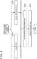
- FIG. 8 is a flow chart illustrating an example of a dictionary data generation process according to the first embodiment of the present invention.
- the image acquisition unit 110 of the terminal 100 first acquires the image (S101), and the angle information acquisition unit 120 acquires the angle information (step S103). Either one of steps S101 and S103 may be executed first, or steps S101 and S103 may be executed in parallel.
- the angle information acquisition unit 120 may acquire the angle information from the platform device 160 once the image acquisition unit 110 acquires in real time the image captured by the camera 150.
- the image acquisition unit 110 may acquire in real time the image captured by the camera 150 once the angle information acquisition unit 120 transmits the angle information to the platform device 160.
- the image acquisition unit 110 may continuously acquire in chronological order the images captured by the camera 150, and the angle information acquisition unit 120 may continuously acquire in chronological order the angle information set in the platform device 160.
- the dictionary data generation unit 130 of the terminal 100 associates the image acquired in step S101 with the angle information acquired in step S103. For example, in a case where both of the image and the angle information are acquired in real time, the dictionary data generation unit 130 associates the image and the angle information acquired at substantially the same time. On the other hand, in a case where the image and the angle information are acquired with a time lag or acquired later, the dictionary data generation unit 130 associates the image and the angle information including a common key.
- the key in this case may be, for example, a time stamp or may be a sequence number or the like allocated separately from the time stamp.
- the dictionary data generation unit 130 generates the dictionary data 210 based on the image and the angle information associated with each other in step S105 (step S107).
- the dictionary data generation unit 130 may apply an already known technique of image-based object recognition to generate the dictionary data 210.
- the dictionary data generation unit 130 may determine that the information is redundant and skip the generation of the dictionary data 210.
- FIG. 9 is a flow chart illustrating an example of a recognition process in the first embodiment of the present invention.
- the image acquisition unit 331 of the robot 300 first acquires the image in the recognition process (step S301).
- the image acquisition unit 331 acquires the image captured by the camera 310, and the image includes, for example, the object obj held by the manipulator 320.
- the dictionary data acquisition unit 332 acquires the dictionary data 210 from the database 200 (step S303).
- the object recognition/angle estimation unit 333 recognizes the object obj based on the image acquired in step S301 and the dictionary data 210 acquired in step S303 (step S305). Note that an already known technique can be applied for the image-based object recognition, and the details will not be described. Furthermore, as described above, in the case where, for example, the dictionary data 210 is generated for a single type of object, or in the case where the object obj included in the image is already identified, the object recognition of step S305 is skipped.
- the object recognition/angle estimation unit 333 prunes the dictionary data 210 (step S307) .
- the number of elements becomes larger in the case where a plurality of different images are associated with the same angle to generate the dictionary data 210 as described above.
- the processing load for matching all of the elements of the dictionary data 210 is enormous, and the benefit of pruning the dictionary data 210 is large.
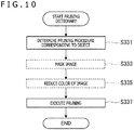
- FIG. 10 is a flow chart illustrating an example of the pruning process in the first embodiment of the present invention.
- FIG. 11 is a conceptual diagram for describing the pruning process illustrated in FIG. 10 .
- the object recognition/angle estimation unit 333 first determines a pruning procedure corresponding to the object obj (step S331).
- the pruning procedure corresponding to the object obj is, for example, set in advance and stored in the database 200 along with the dictionary data 210.
- step S305 illustrated in FIG. 9 is executed, the object recognition/angle estimation unit 333 determines the pruning process according to the recognition result of the object in step S305.
- the following steps S333 and S335 are an example of a process executed according to the pruning procedure corresponding to the object obj in the example illustrated in FIG. 11 .
- the process executed here may vary depending on the type of object.
- the object recognition/angle estimation unit 333 masks the image (step S333) and further reduces the color of the image (step S335).
- the object recognition/angle estimation unit 333 executes the pruning (step S337).
- a plurality of feature parts are extracted from the masked image with reduced color, and elements in the dictionary data 210 in which the positional relationship between a plurality of similarly extracted feature parts is not in common with the image are removed from the target of matching.
- the object obj is a connector.
- the pruning procedure set in the illustrated example focuses on the color of cables (cable 1 to cable 3).
- step S333 illustrated in FIG. 10 parts other than the cables in the image are masked (the mask is indicated as MSK in FIG. 11 ). This removes the influence of the shadow of a terminal cover existing in the masked part.
- the color of the image is reduced in step S335 such that the difference in the color of the cables at both edges (cable 1 and cable 3) is expressed. This allows to easily extract the cables at both edges (cable 1 and cable 3) as two feature parts in each element of the image and the dictionary data 210.
- step S337 illustrated in FIG. 10 the dictionary data 210 is pruned based on the masked image with reduced color.
- cable 1 is positioned on the upper right as viewed from cable 3 in the image.
- cable 1 is positioned on the upper left as viewed from cable 3 in an element group 210b (connector is rotated about the viewing axis) of the dictionary data 210.
- cable 1 is positioned on the lower left as viewed from cable 3 in an element group 210c (connector is reversed). Therefore, the element groups 210b and 210c are removed from the target of matching in step S337.
- the matching is executed only for an element group 210a (as in the image, cable 1 is positioned on the upper right as viewed from cable 1).
- the object recognition/angle estimation unit 333 matches the image with the dictionary data 210 (step S309).
- the matching may be, for example, template matching. Note that an already known technique can be applied for the matching of image, and the details will not be described. Note that although the scores on the basis of objects are calculated as results of matching in the already known image-based object recognition, scores on the basis of angles of objects are calculated in step S307.
- the object recognition/angle estimation unit 333 estimates the angle of the object obj based on the result of the matching in step S309 (S311).
- the estimation result in step S311 may be, for example, an angle indicated by angle information associated with the element of the dictionary data 210 with the highest score calculated in the matching in step S309.
- the object recognition/angle estimation unit 333 determines whether or not the score calculated in the matching in step S309 exceeds a threshold (step S313).
- the score compared with the threshold is, for example, the highest matching score. Alternatively, whether or not a certain top percent (for example, 10%) of the matching scores exceeds the threshold may be determined.
- the dictionary data update unit 335 updates the dictionary data 210 (step S315).
- the process of updating the dictionary data 210 may not be executed.
- the result of the estimation in step S311 is output by the result output unit 334 as necessary.
- FIG. 12 is a flow chart illustrating an example of the dictionary data update process in the first embodiment of the present invention.
- the angle information acquisition/angle estimation unit 337 of the robot 300 first stores the angle information of the object obj provided from the manipulator control unit 336 in the update process (step S351).
- the angle stored in step S351 indicates, for example, an angle of the object obj in the coordinate system on the basis of the manipulator 320.
- the manipulator control unit 336 controls the manipulator 320 to rotate the object obj (step S353).
- step S355 After the object obj is rotated, the angle of the object obj is estimated (step S355) .
- the process of step S355 corresponds to, for example, the process of steps S301 to S311 illustrated in FIG. 9 .
- the image acquisition unit 331 acquires the image (second image) after the rotation of the object obj
- the object recognition/angle estimation unit 333 estimates the angle of the object obj in the image (second image) after the rotation.
- the dictionary data 210 acquired in step S303 executed earlier may be used, and it may be assumed that the object obj is already recognized in step S305 executed earlier.
- the dictionary data update unit 335 determines whether or not the matching score estimated in step S355 exceeds the threshold (step S357). The determination may be executed as in, for example, step S313 illustrated in FIG. 9 . In a case where the matching score does not exceed the threshold in the determination of step S357 (NO), the process of step S353 and step S355 is re-executed. That is, the manipulator control unit 336 controls the manipulator 320 to further rotate the object obj (step S353), and the object recognition/angle estimation unit 333 estimates the angle of the object obj in the image (third image) after the rotation (step S355).
- the angle information acquisition/angle estimation unit 337 re-estimates the initial angle ⁇ 1 from the angle ⁇ 2 estimated in step S355 and the amount of rotation ⁇ of the object obj (step S359).
- the initial angle ⁇ 1 is the angle before the rotation of the object obj and is an angle that cannot be estimated by the object recognition/angle estimation unit 333 with sufficient reliability.
- the angle ⁇ 2 is the angle of the object obj estimated by the object recognition/angle estimation unit 333 based on the image (second image) and the dictionary data 210 after the rotation of the object obj, and it is proved in the determination of step S357 that the angle is estimated with sufficient reliability.
- the amount of rotation ⁇ is calculated based on the angle information of the object obj stored in step S351 and the angle information of the object obj provided from the manipulator control unit 336 at the time of step S353.
- the angle information acquisition/angle estimation unit 337 re-estimates the initial angle ⁇ 1 from an angle ⁇ N+1 estimated in step S355 executed last and a total amount of rotation ⁇ TTL of the object obj in step S353 executed N times.
- the total amount of rotation ⁇ TTL is calculated based on the angle information of the object obj stored in step S351 and the angle information of the object obj provided from the manipulator control unit 336 at the time of step S353.
- the dictionary data update unit 335 associates the angle information corresponding to the initial angle ⁇ 1 re-estimated in step S359 with the image (first image) before the rotation of the object obj acquired in step S301 illustrated in FIG. 9 (step S361). Furthermore, the dictionary data update unit 335 updates the dictionary data 210 based on the image and the angle information associated with each other in step S361 (step S363).
- the update of the dictionary data 210 includes addition of element of the dictionary data 210 and/or replacement of element of the dictionary data 210.
- the dictionary data update unit 335 adds the element of the dictionary data 210 based on the image and the angle information.
- the angle ⁇ 1 is likely to be estimated with high reliability.
- the dictionary data update unit 335 may replace the element of the dictionary data 210 based on the image and the angle information.
- the dictionary data 210 can be updated as described above to accumulate the additional dictionary data 210 regarding the angle or the environmental conditions of the object obj for which the estimation with high reliability by using the dictionary data 210 generated first is difficult. In this way, the robot 300 that uses the dictionary data 210 to estimate the angle of the object obj can autonomously strengthen the dictionary data 210 to improve the robustness of the estimation.
- the dictionary data update process described with reference to FIG. 12 may include an additional process that is a verification process before the update of the dictionary data 210.
- a process of verifying whether or not to execute the dictionary data update process before step S351 illustrated in FIG. 12 may be executed (illustrated as step S371 "verification process 1").
- the image acquisition unit 331 reacquires the image of the object obj before the object obj is rotated in step S353.
- the object recognition/angle estimation unit 333 estimates the angle of the object obj in the reacquired image. In a case where the matching score in the estimation exceeds the threshold (unlike in the estimation in step S311 illustrated in FIG. 9 ), the dictionary data update process is cancelled, and at least the update of the dictionary data of step S363 is not executed.
- the verification process as in the first example is effective for preventing the update of the dictionary data 210 based on information with low reproducibility due to an incidental factor.
- a process of verifying whether or not to update the dictionary data based on prepared angle information and image may be executed after step S361 illustrated in FIG. 12 (illustrated as step S373 "verification process 2").
- the dictionary data update unit 335 generates provisional dictionary data based on the angle information and the image associated in step S361.
- the manipulator control unit 336 controls the manipulator 320 to rotate the object obj, which is opposite to step S353. This causes the object obj to return to the original angle ⁇ 1 .
- the image acquisition unit 331 newly acquires the image of the object obj returned to the original angle ⁇ 1 , and the object recognition/angle estimation unit 333 estimates the angle of the object obj in the image newly acquired by the image acquisition unit 331 based on the provisional dictionary data generated by the dictionary data update unit 335.
- the dictionary data update unit 335 updates the dictionary data 210 of step S363. Otherwise, the dictionary data 210 of step S363 is not updated.
- the second example is effective for, for example, preventing the update of the dictionary data 210 not contributing to the improvement in the reliability of the angle estimation.
- the reliability of the estimation of the angle in a similar image acquired later may not be improved even when the dictionary data 210 is updated based on the image acquired by the image acquisition unit 331.
- the verification process as in the second example is effective for preventing an increase in the capacity of the dictionary data 210 due to unnecessary elements that may not contribute to the improvement in the reliability of the angle estimation.
- the angle information acquisition/angle estimation unit 337 may re-estimate the angle after the rotation of the object obj in the example.
- the angle information acquisition/angle estimation unit 337 may re-estimate the angle after the robot 300 is moved by the motor 350 along with the object obj in another example.
- the environmental conditions at the time that the camera 310 captures the image may be changed by the movement of the robot 300, and the estimation of the angle with high reliability may be possible without rotating the object obj.
- the configuration for moving the robot 300 is described in more detail in a third embodiment described later.
- the movement of the robot 300 may be combined with the rotation of the object obj.
- the angle information acquisition/angle estimation unit 337 may re-estimate the angle after moving the robot 300 along with the object obj in a case where sufficient reliability is still not obtained in the re-estimation of the angle after the rotation of the object obj.
- the process of the re-estimation may be effective in a case where the environmental conditions at the time that the camera 310 captures the image of the object obj are significantly different from the environmental conditions of the camera 150 in generating the dictionary data 210.
- the functions of the system 10 are realized by dispersing the functions to the terminal 100, the database 200, and the robot 300 in the examples illustrated in FIGS. 1 , 2 , and 7 .
- most of the functions of the system 10 may be realized by a server. That is, the functions realized by the processors of the terminal 100 and the robot 300 described in the examples may also be realized by a processor of a server including the database 200.
- the terminal 100 transmits the image of the object obj captured by the camera 150 and the angle information of the object obj acquired from the platform device 160 to the server, and the server associates these to generate the dictionary data 210.
- the robot 300 transmits the image of the object obj captured by the camera 310 to the server, and the server estimates the angle of the object obj based on the image.
- the robot 300 receives the estimation result of the angle from the server.
- the server may ask the robot 300 to rotate the object obj for re-estimating the angle and to acquire the image of the object obj after the rotation.
- the number of servers realizing the functions may not be one, and a plurality of servers dispersed on the network may realize the functions.
- the server realizing the functions may be an apparatus that is separate from the storage including the database 200.
- FIG. 13 is a block diagram illustrating a functional configuration of a robot 300a according to the second embodiment of the present invention.
- the entire functions regarding the generation of the dictionary data 210 and the estimation of the angle of the object obj using the dictionary data 210 are realized by the robot 300a in the present embodiment.
- a process of the control unit 330 of the robot 300a realizes the image acquisition units 110 and 331, the angle information acquisition/angle estimation units 120 and 337, dictionary data generation/update units 130 and 335, the dictionary data acquisition unit 332, the object recognition/angle estimation unit 333, the result output unit 334, and the manipulator control unit 336.
- control unit 330 includes a plurality of processors
- the plurality of processors may cooperate to realize the functions of the components.
- part or all of the functions realized by the processor of the control unit 330 can also be realized by a server.
- the database 200 is stored in the storage of the control unit 330 of the robot 300a.
- the image acquisition units 110 and 331 have the functions of both of the image acquisition unit 110 described with reference to FIG. 2 and the image acquisition unit 331 described with reference to FIG. 7 . That is, the image acquisition units 110 and 331 provide the image of the object obj captured by the camera 310 to the dictionary data generation/update units 130 and 335 in order to generate the dictionary data 210 and provide the image to the object recognition/angle estimation unit 333 in order to use the dictionary data 210 to estimate the angle of the object obj.
- the angle information acquisition/angle estimation units 120 and 337 have the functions of both of the angle information acquisition unit 120 described with reference to FIG. 2 and the angle information acquisition/angle estimation unit 337 described with reference to FIG. 7 . That is, the angle information acquisition/angle estimation units 120 and 337 provide the angle information acquired from the manipulator control unit 336 to the dictionary data generation/update units 130 and 335 in order to generate the dictionary data 210. Furthermore, the angle information acquisition/angle estimation units 120 and 337 calculate the amount of rotation ⁇ of the object obj based on the angle information acquired from the manipulator control unit 336 and further estimate the initial angle ⁇ 1 based on the amount of rotation ⁇ and the angle ⁇ 2 estimated by the object recognition/angle estimation unit 333 in order to update the dictionary data 210.
- the angle information acquired by the angle information acquisition/angle estimation unit 337 of the robot 300 may indicate the angle of the object obj on the basis of the coordinate system of the manipulator 320.
- the angle of the object obj indicated by the angle information acquired by the angle information acquisition/angle estimation unit 337 may be changed not only by the amount of rotation of the manipulator 320 set by the manipulator control unit 336, but also by the amounts of operation of the other constituent elements of the robot 300 connected to the manipulator 320, such as arms.
- which surface of the object obj is held by the manipulator 320 may also vary from time to time. Therefore, using the dictionary data 210 to estimate the angle of the object obj in the image may be beneficial even when the same manipulator 320 as in the case of generating the dictionary data 210 holds the object obj.
- the dictionary data generation/update units 130 and 335 have the functions of both of the dictionary data generation unit 130 described with reference to FIG. 2 and the dictionary data update unit 335 described with reference to FIG. 7 . That is, the dictionary data generation/update units 130 and 335 generate the dictionary data 210 based on the image acquired by the image acquisition units 110 and 331 and the angle information acquired by the angle information acquisition/angle estimation units 120 and 337 in order to generate the dictionary data 210.
- the dictionary data generation/update units 130 and 335 update the dictionary data 210 according to the results of the estimation of the angle of the object obj estimated by the object recognition/angle estimation unit 333 and the results of the re-estimation of the angle re-estimated by the angle information acquisition/angle estimation units 120 and 337 in order to use the dictionary data 210 to estimate the angle of the object obj.
- the functions of the system 10 according to the first embodiment can be realized by a single apparatus, such as the robot 300a.
- the system 10 is realized by a single apparatus.
- the configuration of the system 10 can be realized by various device configurations.
- the system 10 may include a plurality of robots 300, and each of the robots 300 may generate the dictionary data 210 and estimate the angle of the object by using the dictionary data 210.
- the dictionary data 210 stored in the database 200 is shared by the plurality of robots 300.
- a server including the database 200 may realize the functions realized by the control unit 330 of the robot 300a in the second embodiment.
- the robot 300a in generating the dictionary data transmits the image of the object obj captured by the camera 310 and the angle information of the object obj acquired from the manipulator control unit 336 to the server, and the server associates these to generate the dictionary data 210.
- the robot 300a in estimating the angle transmits the image of the object obj captured by the camera 310 to the server, and the server estimates the angle of the object obj based on the image.
- the robot 300a receives the estimation result of the angle from the server.
- the server may also ask the robot 300a to rotate the object obj for re-estimating the angle and to acquire the image of the object obj after the rotation in the case where the reliability of the estimated angle does not exceed the threshold.
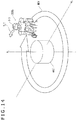
- FIG. 14 is a schematic diagram for describing the third embodiment of the present invention.
- a robot 300b in the present embodiment moves relative to the object obj instead of using the manipulator to hold the object.
- the movement of the robot 300b includes revolving REV around the object.
- the object obj rotates about the axis A 1 in the images captured by the camera 310.
- the movement of the robot 300b also includes tilting TLT with respect to the object obj of the camera 310.
- the object obj rotates about the axis A 2 in the images captured by the camera 310.
- FIG. 15 is a block diagram illustrating a functional configuration of the robot 300b according to the third embodiment of the present invention.
- the robot 300b according to the present embodiment is different from the robot 300a illustrated in FIG. 13 in that the robot 300b includes a motor control unit 339 that controls the motor 350 in place of the manipulator control unit 336 that controls the manipulator 320.
- the motor control unit 339 controls the motor 350 of the robot 300.
- the motor 350 includes a motor for activating the joint structure of the robot 300 or rotating the wheel of the robot 300b to thereby move the robot 300b or change the posture of the robot 300b.
- the motor control unit 339 controls the motor 350 to revolve the robot 300b around the object obj and/or to tilt the robot 300b with respect to the object obj of the camera 310.
- Angle information acquisition/angle estimation units 120 and 337b acquire the angle information indicating the angle of the object obj.
- the angle information is acquired by, for example, using a plurality of time-series images acquired by the image acquisition unit 331 during the movement of the robot 300 and the camera 310 to execute image-based simultaneous localization and mapping (SLAM).
- the SLAM may be executed by using measurement results of the other sensor 340 included in the robot 300a, such as a depth sensor and a laser range scanner.
- the angle information acquisition/angle estimation units 120 and 337b use the SLAM to specify the amount of movement of the camera 310 and then acquire the angle information of the object obj based on the separately specified positional relationship between the camera 310 and the object obj.
- the angle information acquisition/angle estimation units 120 and 337b may specify the amount of movement of the camera 310 based on values of the motor 350 controlled by the motor control unit 339.
- the present embodiment allows to use the angle information acquired as described above to generate the dictionary data 210. Furthermore, in the case where the object recognition/angle estimation unit 333 cannot estimate the angle with sufficient reliability based on the dictionary data 210, the motor control unit 339 can control the motor 350 to rotate the object obj in the image to thereby re-estimate the angle and update the dictionary data 210.
- the relative movement of the camera 310 with respect to the object obj is an example of a physical operation regarding the object obj executed upon the re-estimation of the angle of the object obj.
- the dictionary data 210 for estimating the angle of the object obj can be generated even in a case where the object obj is large or in a case where the object obj is small but cannot be moved.
- the robot 300b may also include the manipulator 320 and the manipulator control unit 336 as described with reference to FIG. 7 and may use the manipulator 320 to rotate the object obj as in the first and second embodiments in the case where the object obj can be held.
- the robot 300 in the system 10 according to the first embodiment may include the motor control unit 339 in place of the manipulator control unit 336 or in addition to the manipulator control unit 336.
- the size of the platform device 160 (or the robot 300) used to generate the dictionary data 210 and the size of the robot 300 that uses the dictionary data 210 to estimate the angle of the object obj are different, there may be a case in which although the platform device 160 (or the manipulator 320) can be used to rotate the object obj in order to generate the dictionary data 210, it is difficult to rotate the object obj in updating the dictionary data 210. There may also be the opposite case.
- the motor control unit 339 may control the motor 350 to move the camera 310 along with the object obj.
- the manipulator control unit 336 controls the manipulator 320 to prevent the angle of the object obj in the image from changing.
- the manipulator control unit 336 holds the positional relationship between the manipulator 320 and the camera 310 and the angle of the object obj held by the manipulator 320 while the motor control unit 339 controls the motor 350 to move the robot 300.
- the camera 310 can be moved along with the object obj to change, for example, the environmental conditions when the camera 310 captures the image, without changing the angle of the object obj in the image.
- the estimation with high reliability may be enabled by changing the environmental conditions.
- a plurality of elements associating a plurality of images acquired under different environmental conditions with common angle information can be included in the dictionary data 210 in generating the dictionary data 210 to thereby improve the robustness of the estimation of the angle.
- the motor control unit 339 first controls the motor 350 to move the camera 310 along with the object obj in the update process of the dictionary data 210.
- the image acquisition unit 331 acquires the image (second image) after the movement of the object obj
- the object recognition/angle estimation unit 333 re-estimates the angle of the object obj in the image (second image) after the movement.
- the dictionary data update unit 335 updates the dictionary data based on the angle information corresponding to the angle of the re-estimated object obj and the image (first image) acquired by the image acquisition unit 331 before the movement of the object obj.
- the movement of the camera 310 along with the object obj is the physical operation regarding the object obj executed in the re-estimation of the angle of the object obj.
- the object recognition/angle estimation unit 333 performs both of the "first angle estimation function" and the "second angle estimation function.”
- FIG. 16 is a block diagram illustrating an example of the hardware configuration of the information processing apparatus according to the embodiments of the present invention.
- the information processing apparatus 900 includes a processor 901, a memory 903, an input apparatus 905, an output apparatus 907, and a bus 909.
- the information processing apparatus 900 may further include a storage 911, a drive 913, a connection port 915, and a communication apparatus 917.
- the processor 901 includes, for example, processing circuits, such as a central processing unit (CPU), a digital signal processor (DSP), an application specific integrated circuit (ASIC), and/or a field-programmable gate array (FPGA).
- the processor 901 functions as an operation processing apparatus and a control apparatus and controls the operation of the information processing apparatus 900 according to programs recorded in the memory 903, the storage 911, or a removable recording medium 919.
- the memory 903 includes, for example, a read only memory (ROM) and a random access memory (RAM).
- the ROM stores, for example, programs for the processor 901, operation parameters, and the like.
- the RAM primarily stores, for example, a program deployed at the execution of the processor 901, parameters in executing the program, and the like.
- the input apparatus 905 is, for example, an apparatus operated by the user, such as a mouse, a keyboard, a touch panel, a button, and various switches.
- the input apparatus 905 may not be integrated with the information processing apparatus 900 and may be, for example, a remote controller that transmits a control signal through wireless communication.
- the input apparatus 905 includes an input control circuit that generates an input signal based on information input by the user and outputs the input signal to the processor 901.
- the output apparatus 907 includes an apparatus that can use senses, such as sight, hearing, and touch, to output information toward the user.
- the output apparatus 907 may include, for example, a display apparatus, such as a liquid crystal display (LCD) and an organic electro-luminescence (EL) display, a voice output apparatus, such as a speaker and a headphone, and a vibrator.
- the output apparatus 907 outputs the result obtained in the process of the information processing apparatus 900 in a form of image, such as text and picture, sound, such as voice and audio, or vibration.
- the storage 911 includes, for example, a magnetic storage device such as a hard disk drive (HDD), a semiconductor storage device, an optical storage device, a magneto-optical storage device, or the like.
- the storage 911 stores, for example, programs for the processor 901, various types of data read at the execution of the programs or generated by the execution of the programs, various types of data acquired from the outside, and the like.
- the drive 913 is a reader/writer for the removable recording medium 919, such as a magnetic disk, an optical disk, a magneto-optical disk, and a semiconductor memory.
- the drive 913 reads information recorded in the installed removable recording medium 919 and outputs the information to the memory 903.
- the drive 913 also writes various types of data to the installed removable recording medium 919.
- the connection port 915 is a port for connecting an external connection device 921 to the information processing apparatus 900.
- the connection port 915 may include, for example, a USB port, an IEEE 1394 port, a small computer system interface (SCSI) port, and the like.
- the connection port 915 may also include an RS-232C port, an optical audio terminal, a high-definition multimedia interface (HDMI) (registered trademark) port, and the like.
- HDMI high-definition multimedia interface
- the communication apparatus 917 is connected to a network 923.
- the network 923 may be, for example, an open communication network, such as the Internet, in which a large number of unspecified apparatuses are connected or may be, for example, a closed communication network, such as Bluetooth (registered trademark), in which limited apparatuses, such as two apparatus, are connected.
- the communication apparatus 917 may include, for example, a local area network (LAN), Bluetooth (registered trademark), Wi-Fi, or a communication card for wireless USB (WUSB).
- the communication apparatus 917 uses a predetermined protocol according to the network 923 to transmit and receive signals, data, and the like to and from other information processing apparatuses.
- a general-purpose member may be used to provide each of the constituent elements, or hardware specific to the function of each constituent element may be used to provide the constituent element.
- those skilled in the art can appropriately change the configuration of the information processing apparatus 900 according to the technical level at the time of the implementation.
- the embodiments of the present invention may include, for example, the system, the jig, and the information processing apparatus as described above, an information processing method executed by the information processing apparatus, a program for operating the information processing apparatus, and a non-transitory tangible medium recording the program.
- Object recognition/angle estimation unit 334 ... Result output unit, 335 ... Dictionary data update unit, 336 ... Manipulator control unit, 337 ... Angle information acquisition/angle estimation unit, 339 ... Motor control unit, 340 ... sensor, 350 ... Motor.
Landscapes
- Engineering & Computer Science (AREA)
- Theoretical Computer Science (AREA)
- Mechanical Engineering (AREA)
- Robotics (AREA)
- Physics & Mathematics (AREA)
- General Physics & Mathematics (AREA)
- Computer Vision & Pattern Recognition (AREA)
- Data Mining & Analysis (AREA)
- Artificial Intelligence (AREA)
- Evolutionary Computation (AREA)
- Evolutionary Biology (AREA)
- General Health & Medical Sciences (AREA)
- Bioinformatics & Computational Biology (AREA)
- Bioinformatics & Cheminformatics (AREA)
- Life Sciences & Earth Sciences (AREA)
- Geometry (AREA)
- Health & Medical Sciences (AREA)
- Computing Systems (AREA)
- Databases & Information Systems (AREA)
- General Engineering & Computer Science (AREA)
- Medical Informatics (AREA)
- Software Systems (AREA)
- Multimedia (AREA)
- Automation & Control Theory (AREA)
- Image Analysis (AREA)
- Manipulator (AREA)
- Studio Devices (AREA)
- Image Processing (AREA)
Abstract
Description
- The present invention relates to a system, a jig, an information processing apparatus, an information processing method, and a program.
- Image-based object recognition is a general technique in recent years. In the image-based object recognition, for example, an amount of features of an image captured by an imaging apparatus is extracted, and the amount of features is matched with an amount of features registered in advance as dictionary data to thereby recognize an object in the image. Here, a change in the angle of the object in the image also changes the amount of features, and therefore, the dictionary data needs to be prepared for each angle of the object in order to increase the availability of the object recognition.
-
PTL 1 andPTL 2 are examples of a technique for preparing the dictionary data for each angle of the object in the image-based object recognition.PTL 1 describes a technique of recognizing an object based on eight images obtained by rotating the object at 45-degree intervals.PTL 2 describes a technique of learning a model of an object by recognizing common parts from a large number of images obtained by rotating the object in a horizontal angle direction and a zenith angle direction in five-degree increments or the like. -
- [PTL 1]
Japanese Patent Laid-Open No.2003-346152 - [PTL 2]
U.S. Patent Application Publication No. 2013/0202212 - The techniques are techniques for recognizing the object in the image, that is, estimating what the object in the image is, and it is not intended to draw out additional information from the image. However, in view of the diversified fields in which the technique of object recognition is used in recent years, it can be advantageous to provide additional information regarding the object based on the image.
- Therefore, an object of the present invention is to provide new and improved system, jig, information processing apparatus, information processing method, and program that can estimate an angle of an object based on an image.
- An aspect of the present invention provides a system including one or a plurality of information processing apparatuses that individually or cooperatively realize functions including a first image acquisition function of acquiring a first image of an object, an angle information acquisition function of acquiring angle information indicating an angle of the object in the first image, a dictionary data generation function of generating dictionary data based on the first image and the angle information, a second image acquisition function of acquiring a second image of the object different from the first image, and an angle estimation function of estimating an angle of the object in the second image based on the second image and the dictionary data.
- In addition, another aspect of the present invention provides a jig capable of being attached to a platform device, the platform device including a base portion that rotates about a first axis, a pair of supports fixed at positions symmetric with respect to the first axis on the base portion, a pair of arms connected to the pair of supports, respectively, so as to be pivotable about a second axis orthogonal to the first axis, on an opposite side of the base portion, a holder fixed between edges of the pair of arms, on an opposite side of the pair of supports, and a control unit that sets an angle of the base portion rotating about the first axis and an angle of the pair of arms pivoting about the second axis. The jig includes an attachment member capable of being attached to the holder of the platform device, an object holder for attaching the object, and a connecting member that connects the attachment member and the object holder and defines a positional relationship between the attachment member and the object holder such that the object attached to the object holder is positioned near an intersection of the first axis and the second axis when the attachment member is attached to the holder of the platform device.
- In addition, yet another aspect of the present invention provides an information processing apparatus including a processor that realizes functions including an image acquisition function of acquiring a plurality of images of an object different from each other, an angle information acquisition function of acquiring angle information common to the plurality of images, the angle information indicating an angle of the object, and a dictionary data generation function of generating dictionary data based on the plurality of images and the angle information common to the plurality of images.
- In addition, yet another aspect of the present invention provides an information processing apparatus including a processor that realizes functions including a dictionary data acquisition function of acquiring a first image of an object and dictionary data generated based on angle information indicating an angle of the object in the first image, an image acquisition function of acquiring a second image of the object different from the first image, and an angle estimation function of estimating an angle of the object in the second image based on the second image and the dictionary data.
- In addition, yet another aspect of the present invention provides an information processing method including a step of acquiring a plurality of images of an object different from each other, a step of acquiring angle information common to the plurality of images, the angle information indicating an angle of the object, and a step of using a processor to generate dictionary data based on the plurality of images and the angle information common to the plurality of images.
- In addition, yet another aspect of the present invention provides an information processing method including a step of acquiring dictionary data generated based on a first image of an object and angle information indicating an angle of the object in the first image, a step of acquiring a second image of the object different from the first image, and a step of using a processor to estimate an angle of the object in the second image based on the second image and the dictionary data.
- In addition, yet another aspect of the present invention provides a program for causing a processor to realize functions including an image acquisition function of acquiring a plurality of images of an object different from each other, an angle information acquisition function of acquiring angle information common to the plurality of images, the angle information indicating an angle of the object, and a dictionary data generation function of generating dictionary data based on the plurality of images and the angle information common to the plurality of images.
- In addition, yet another aspect of the present invention provides a program for causing a processor to realize functions including a dictionary data acquisition function of acquiring dictionary data generated based on a first image of an object and angle information indicating an angle of the object in the first image, a second image acquisition function of acquiring a second image of the object different from the first image, and an angle estimation function of estimating an angle of the object in the second image based on the second image and the dictionary data.
-
-
FIG. 1 is a schematic diagram illustrating a system according to a first embodiment of the present invention. -
FIG. 2 is a block diagram illustrating a functional configuration of a terminal in the system illustrated inFIG. 1 . -
FIG. 3 is a schematic perspective view illustrating a configuration of a platform device and a jig used in the system illustrated inFIG. 1 . -
FIG. 4 is a cross-sectional view taken along line I-I ofFIG. 3 . -
FIG. 5 is a conceptual diagram for describing dictionary data generated in the first embodiment of the present invention. -
FIG. 6 is a diagram for describing a schematic configuration of a robot in the system illustrated inFIG. 1 . -
FIG. 7 is a block diagram illustrating a functional configuration of the robot in the system illustrated inFIG. 1 . -
FIG. 8 is a flow chart illustrating an example of a dictionary data generation process in the first embodiment of the present invention. -
FIG. 9 is a flow chart illustrating an example of a recognition process in the first embodiment of the present invention. -
FIG. 10 is a flow chart illustrating an example of a pruning process in the first embodiment of the present invention. -
FIG. 11 is a conceptual diagram for describing the pruning process illustrated inFIG. 10 . -
FIG. 12 is a flow chart illustrating an example of a dictionary data update process in the first embodiment of the present invention. -
FIG. 13 is a block diagram illustrating a functional configuration of a robot according to a second embodiment of the present invention. -
FIG. 14 is a schematic diagram for describing a third embodiment of the present invention. -
FIG. 15 is a block diagram illustrating a functional configuration of a robot according to the third embodiment of the present invention. -
FIG. 16 is a block diagram illustrating an example of a hardware configuration of an information processing apparatus in the embodiments of the present invention. - Hereinafter, some embodiments of the present invention will be described in detail with reference to the attached drawings. Note that in the present specification and the drawings, overlapping description will be omitted by providing the same reference signs to the constituent elements with substantially the same functional configurations.
-
FIG. 1 is a schematic diagram illustrating asystem 10 according to a first embodiment of the present invention. With reference toFIG. 1 , thesystem 10 includes aterminal 100, adatabase 200, and arobot 300 connected to each other through a network NW. Acamera 150 and aplatform device 160 are connected to theterminal 100. Therobot 300 includes acamera 310 and amanipulator 320. - In the
system 10, thecamera 150 captures an image of an object obj attached to theplatform device 160 through ajig 170 described later. Theterminal 100 acquires the image from thecamera 150 and acquires angle information indicating an angle of the object obj from theplatform device 160. Note that in the following description, the angle of the object obj is an angle in a three-dimensional space, such as an angle indicated by an amount of rotation about three axes in an orthogonal coordinate system, unless otherwise specifically stated. Theterminal 100 generates dictionary data based on the acquired image and angle information (as well as identification information of the object obj). The generated dictionary data is stored in thedatabase 200. - On the other hand, the
robot 300 uses thecamera 310 to capture an image of the object obj while themanipulator 320 holds the object obj. Therobot 300 recognizes the object obj in the image based on the captured image and the dictionary data acquired from thedatabase 200 and further estimates the angle of the object obj in the image. - In this way, the
robot 300 can recognize the object obj and further estimate the angle of the object obj held by themanipulator 320. The angle indicates, for example, the degree of rotation of the object obj with respect to a reference posture. Therobot 300 can, for example, control themanipulator 320 based on the estimation result of the angle to rotate the object obj to thereby set the object obj to a desirable posture. - The
system 10 is useful for, for example, using therobot 300 to automate the work of arranging or organizing commodities. Thesystem 10 is also useful for, for example, specifying how to rotate the object obj in order to read information (such as a printed code and a radio frequency identifier (RFID)) arranged at a predetermined part of the object obj. Note that the uses of thesystem 10 are not limited to the examples, and there can be various other uses. -
FIG. 2 is a block diagram illustrating a functional configuration of the terminal 100 in the system illustrated inFIG. 1 . With reference toFIG. 2 , the terminal 100 includes animage acquisition unit 110, an angleinformation acquisition unit 120, and a dictionarydata generation unit 130. The terminal 100 is, for example, a personal computer, a tablet, a smartphone, or the like, and functions of the components are realized by a hardware configuration of an information processing apparatus described later. Specifically, for example, the functions of theimage acquisition unit 110, the angleinformation acquisition unit 120, and the dictionarydata generation unit 130 are realized by a processor included in the information processing apparatus.Dictionary data 210 generated by the dictionarydata generation unit 130 is stored in thedatabase 200 connected to the terminal 100 through the network. The function of thedatabase 200 is realized by storage of one or a plurality of information processing apparatuses connected to the network. Note that in a case where the terminal 100 includes a plurality of processors, the plurality of processors may cooperate to realize the functions of the components. - In addition, as described later, part or all of the functions realized by the processor of the terminal 100 can also be realized by a server. Hereinafter, the functions of the components will be described.
- The
image acquisition unit 110 acquires the image of the object obj captured by thecamera 150. Here, thecamera 150 is an example of an imaging apparatus that captures an image of an object. Specifically, thecamera 150 is, for example, a digital camera including an image sensor, and theimage acquisition unit 110 receives image data generated by thecamera 150. Although thecamera 150 is connected to the terminal 100 through a wired communication interface, such as a universal serial bus (USB), in the illustrated example, thecamera 150 may be connected to the terminal 100 through a wireless communication interface, such as Bluetooth (registered trademark), in another example. Alternatively, thecamera 150 may be built in the terminal 100 and may transmit the image data to theimage acquisition unit 110 through a bus. - The angle
information acquisition unit 120 acquires the angle information indicating the angle of the object obj from theplatform device 160. Here, in the present embodiment, the angle information acquired by the angleinformation acquisition unit 120 of the terminal 100 indicates an angle of the object obj on the basis of a coordinate system of theplatform device 160. Note that a case in which the angleinformation acquisition unit 120 generates the angle information of the object obj, transmits the angle information to theplatform device 160, and provides the angle information to the dictionarydata generation unit 130 is also included in the case in which "the angleinformation acquisition unit 120 acquires the angle information." In this case, theplatform device 160 sets the angle of holding the object obj according to the angle information received from the angleinformation acquisition unit 120. In the present embodiment, theplatform device 160 is an example of holding means for holding the object obj. Similar to thecamera 150, theplatform device 160 may also be connected to the terminal 100 through a wired communication interface or may be connected to the terminal 100 through a wireless communication interface. - As described above, the angle of the object obj is an angle in the three-dimensional space, such as an angle indicated by an amount of rotation about three axes in the orthogonal coordinate system. Therefore, the angle
information acquisition unit 120 expresses the angle information by, for example, the amount of rotation equivalent to the difference between the current posture and the reference posture of the object obj. Here, the reference posture is, for example, a posture of the object obj when theplatform device 160 is reset. Alternatively, the reference posture may be a posture of the object obj when theimage acquisition unit 110 first acquires the image of the object obj to generate thedictionary data 210. - The dictionary
data generation unit 130 generates thedictionary data 210 based on the image acquired by theimage acquisition unit 110, the identification information of the object obj, and the angle information acquired by the angleinformation acquisition unit 120. Here, the identification information of the object obj may be specified by any means. For example, the identification information of the object obj may be specified based on information input to the terminal 100 by the user. The identification information of the object obj may also be specified by matching the image acquired by theimage acquisition unit 110 with dictionary data separately provided for image-based object recognition. Alternatively, the dictionarydata generation unit 130 may allocate the identification information to the object obj commonly included in a plurality of images acquired by theimage acquisition unit 110. - Note that an already known technique in image-based object recognition can be appropriately used for the combination of the image and the identification information of the object obj in the information used for generating the
dictionary data 210 in the present embodiment. For example, the dictionarydata generation unit 130 may use an appropriate method used in the image-based object recognition to extract an amount of features from the image and may associate the extracted amount of features with the identification information and the angle information of the object obj. In addition, for example, the dictionarydata generation unit 130 may use the identification information of the object obj classified and labeled by an appropriate method used in the image-based object recognition. - In addition, although the
dictionary data 210 is generated based on the identification information of the object obj in the description of the present embodiment, thedictionary data 210 may not be generated based on the identification information of the object obj. For example, in a case where thesystem 10 is provided for a single type of object obj, thedictionary data 210 may not include the identification information of the object obj. On the other hand, in the case where thedictionary data 210 includes the identification information of the object obj as in the present embodiment, a plurality of types of objects obj can be recognized, and then the angles of the objects obj can be further estimated. - Hereinafter, the configuration of the
platform device 160 used with the terminal 100 in thesystem 10 according to the present embodiment and the configuration of thejig 170 for attaching the object obj to theplatform device 160 will be further described. -
FIG. 3 is a schematic perspective view illustrating the configuration of theplatform device 160 and thejig 170 used in the system illustrated inFIG. 1 .FIG. 4 is a cross-sectional view taken along line I-I ofFIG. 3 . With reference toFIGS. 3 and4 , theplatform device 160 includes abase 161, a pair ofsupports 162, a pair ofarms 163, a pair ofpins 164, aholder 165, abeam 166, and acontrol unit 167. Thejig 170 includes anattachment member 171, a connectingmember 172, anobject holder 173, and abackground plate 174. Note that thebackground plate 174 is not illustrated inFIG. 3 . Hereinafter, each component will be described. - In the
platform device 160, thebase 161 is, for example, a rotary table. Thebase 161 is driven by a motor (not illustrated) controlled by thecontrol unit 167 and rotates about an axis A1. Here, the axis A1 is orthogonal to an optical axis (illustrated as an axis A3 inFIG. 4 ) of thecamera 150. The pair ofsupports 162 are fixed on the base 161 at positions symmetric with respect to the axis A1. Therefore, the midpoint of the pair ofsupports 162 substantially coincides with the axis A1. Thepins 164 are used to connect the pair ofarms 163 to the pair ofsupports 162, respectively, on the opposite side of thebase 161. Thepins 164 are positioned on an axis A2 orthogonal to the axis A1. Each of the pair ofarms 163 is pivotable about the axis A2. Specifically, the pair ofsupports 162 and thepins 164 are connected through gears, or thepins 164 and the pair ofarms 163 are connected through gears. A motor (not illustrated) controlled by thecontrol unit 167 is connected to the gears, and the pair ofarms 163 pivot about the axis A2. - The
holder 165 is fixed between edges of the pair ofarms 163 through thebeam 166, on the opposite side of the pair ofsupports 162. Although theholder 165 is a member provided with a camera in a case where, for example, theplatform device 160 is used as an automatic platform for camera, theattachment member 171 of thejig 170 is attached to theholder 165 in the present embodiment as described later. As described above, when the pair ofarms 163 pivot about the axis A2, theholder 165 revolves about the axis A2. Here, while theholder 165 revolves about the axis A2 according to the configuration of the pair ofarms 163, anattachment surface 165s of theholder 165 is maintained to face the axis A2. - The
control unit 167 is, for example, a microcontroller incorporated into theplatform device 160, and thecontrol unit 167 controls the motor as described above to control the rotation of thebase 161 and the pivot of the pair ofarms 163. Thecontrol unit 167 controls the motor according to, for example, a predetermined procedure or an instruction from the terminal 100. In this way, thecontrol unit 167 sets the angle of the rotation of the base 161 about the axis A1 and the angle of the pivot of the pair ofarms 163 about the axis A2. The angleinformation acquisition unit 120 of the terminal 100 acquires, for example, angle information that is information indicating the values of the angles set by thecontrol unit 167. - The
platform device 160 described above is principally distributed as an apparatus that automates the pan (rotation about axis A1) and the tilt (switch about axis A2) of the camera attached to theholder 165. The present embodiment is intended to use theplatform device 160 to automate the setting of the angle of the object obj to thereby efficiently generate thedictionary data 210 covering various angles. However, in a case where the object obj is directly attached to theholder 165 of theplatform device 160, theholder 165 swings about the axis A2 when the pair ofarms 163 pivot, and as a result, the position of the object obj becomes significantly out of the optical axis of the camera 150 (illustrated as axis A3 inFIG. 4 ) . Therefore, the object obj is attached to theplatform device 160 through thejig 170 as described below in the present embodiment. - In the
jig 170, theattachment member 171 is a member that can be attached to theholder 165 of theplatform device 160. For example, theattachment member 171 is provided with an attachment structure corresponding to the structure for fixing the camera provided on theholder 165. Specifically, in a case where theholder 165 is provided with a screw for fixing the camera, theattachment member 171 is provided with a screw hole. Alternatively, theattachment member 171 may be provided with an attachment structure that can be used regardless of the structure of theholder 165. Specifically, theattachment member 171 may be provided with a clip for sandwiching theholder 165, a belt wound around theholder 165, or the like. - The
object holder 173 is a member for attaching the object obj. For example, theobject holder 173 is provided with an attachment structure that can fix the object obj while reducing the area of contact with the object obj as much as possible. This is because the contact area of the attachment structure and the object obj may become an occlusion region in the image of the object obj captured by thecamera 150. Specifically, theobject holder 173 may be provided with a clip for sandwiching the object obj, a hook for grasping the object obj, an adhesive surface for attaching the object obj, or the like. In addition, theobject holder 173 may be provided with a magnet for the object obj that is a magnetic substance. - The connecting
member 172 connects theattachment member 171 and theobject holder 173. In addition, the connectingmember 172 defines the positional relationship between theattachment member 171 and theobject holder 173 so that the object obj attached to theobject holder 173 is positioned near the intersection of the axis A1 and the axis A2 when theattachment member 171 is attached to theholder 165 of theplatform device 160. For example, the connectingmember 172 is connected to theattachment member 171 so as to extend along the pair ofarms 163 when theattachment member 171 is attached to theholder 165. In this case, the length of the connectingmember 172 in the direction along the pair ofarms 163 is substantially equivalent to the distance obtained by subtracting the thicknesses of theattachment member 171 and theobject holder 173 and a half of the thickness of the object obj from the distance between theholder 165 and the axis A2. The connectingmember 172 may have a structure that can adjust the length in the direction along thearms 163. This allows to adjust the length of the connectingmember 172 according to the size of the object obj to bring the center of the object obj close to the intersection of the axis A1 and the axis A2. - The object obj attached to the
platform device 160 through thejig 170 as described above is positioned near the intersection of the axis A1 and the axis A2. Therefore, even when thebase 161 of theplatform device 160 rotates about the axis A1 or when the pair ofarms 163 pivot about the axis A2, there is substantially no change in the position of the object obj, and the position does not become significantly out of the optical axis of the camera 150 (illustrated as axis A3 inFIG. 4 ). Therefore, when thecontrol unit 167 of theplatform device 160 sets the angle of the rotation of the base 161 about the axis A1 and the angle of the pivot of the pair ofarms 163 about the axis A2, the angles can be regarded as the amount of rotation of the object obj about the axis A1 and the axis A2 in the present embodiment. - Note that in the case where the
platform device 160 and thejig 170 are used, although the object obj is not rotated about the axis A3 orthogonal to the axis A1 and the axis A2, that is, the optical axis of thecamera 150, the rotation about the axis A3 can be accurately complemented by plane rotation of the image captured by thecamera 150. In addition, although the object obj is on the optical axis of thecamera 150 in the description above for simplification, the object obj may not be on the optical axis of thecamera 150. - The
background plate 174 is attached to the connectingmember 172 or theobject holder 173 and provides the background of the object obj. For example, thebackground plate 174 may be provided with an attachment structure for selectively attaching a screen. The screen can include, for example, a plurality of screens formed by different materials. Examples of the materials include paper, cloth, and film. The screens may also include a plurality of screens in different colors or different reflection characteristics. The screen can be exchanged to provide a plurality of exchangeable backgrounds of the object obj with different materials, colors, reflection characteristics, or the like. In addition, thebackground plate 174 may be, for example, removably attached to the connectingmember 172 or theobject holder 173. In this case, a plurality ofbackground plates 174 can be selectively attached to provide a plurality of exchangeable backgrounds of the object obj with different materials, colors, reflection characteristics, or the like. Specifically, thebackground plate 174 may include, for example, a plurality ofbackground plates 174 in which the surfaces facing the object obj are formed by different materials. Examples of the materials include paper, cloth, and film. Thebackground plate 174 may also include a plurality ofbackground plates 174 in which the surfaces facing the object obj are in different colors or different reflection characteristics. -
FIG. 5 is a conceptual diagram for describing the dictionary data generated in the first embodiment of the present invention.FIG. 5 illustrates thedictionary data 210 associated with the object obj (connector in the illustrated example) specified by certain identification information. In the illustrated example, the angle of the object obj is a vector quantity indicated by the amount of rotation about three axes (X-axis, Y-axis, and Z-axis) of the orthogonal coordinate system in the three-dimensional space. As for the angle of the object obj, thedictionary data 210 includes at least NX×NY×NZ elements defined by dividing the entire circumference into Nx elements regarding the amount of rotation (rot_X) about the X-axis, dividing the entire circumference into NY elements regarding the amount of rotation (rot_Y) about the Y-axis, and dividing the entire circumference into NZ elements regarding the amount of rotation (rot_Z) about the Z-axis. Each element is associated with information corresponding to at least one image of the object obj. Here, the information corresponding to the image of the object obj can be, for example, an amount of features extracted from the image captured by thecamera 150 when the object obj is at an angle indicated by the amount of rotation (rot_X, rot_Y, rot_Z). - Note that in the example, the division widths of the amount of rotation (rot_X, rot_Y, rot_Z) about the axes may be different (that is, at least one of NX, NY, and NZ may be different from others). In addition, the amount of rotation may not be equally divided. For example, in a case where there is an angle unlikely to be estimated with high reliability in the estimation of the angle of the object obj described later, the division width of the amount of rotation near the amount of rotation corresponding to the angle may be set smaller than the division width of the other parts.
- For example, in a case where the
camera 310 of therobot 300 captures an image of the object obj at an unknown angle, the amount of features extracted from the captured image and the amount of features associated with the element of thedictionary data 210 can be matched to estimate the angle of the object obj. - Here, the
dictionary data 210 may include a plurality of elements generated based on the angle information of the same object obj and a plurality of different images. In this case, the number of elements of thedictionary data 210 is larger than NX×NY×NZ. The environmental conditions in capturing the plurality of images may vary between the plurality of images associated with the same angle information, for example. The environment conditions can be, for example, the arrangement of the background or the light. Generating thedictionary data 210 under a plurality of different environmental conditions can provide thedictionary data 210 that can estimate the angle of the object obj under various environmental conditions. - In the case described above, the
image acquisition unit 110 of the terminal 100 acquires a plurality of different images of the object obj. For example, theimage acquisition unit 110 may acquire images of the object obj when thecontrol unit 167 of theplatform device 160 sets the same angle before and after the background of the object obj is exchanged by using thebackground plate 174 of thejig 170. In this case, the dictionarydata generation unit 130 generates a plurality of elements of thedictionary data 210 based on the plurality of images with different backgrounds, the identification information of the object obj common to the plurality of images, and the angle information indicating the angle of the object obj common to the plurality of images. -
FIG. 6 is a diagram for describing a schematic configuration of therobot 300 in the system illustrated inFIG. 1 . With reference toFIG. 6 , therobot 300 includes thecamera 310, themanipulator 320, acontrol unit 330, asensor 340, and amotor 350. Therobot 300 can, for example, use themanipulator 320 to hold the object obj and use thecamera 310 to capture the image of the object obj according to the control of thecontrol unit 330. In the present embodiment, themanipulator 320 is also an example of the holding means for holding the object obj, similar to theplatform device 160. Thecontrol unit 330 is realized by, for example, a hardware configuration of an information processing apparatus described later. - The
sensor 340 includes sensors for acquiring various measurement values used by therobot 300 or transmitted from therobot 300 to another apparatus. Specifically, thesensor 340 may include an acceleration sensor, an angular velocity sensor, a geomagnetic sensor, and/or a global navigation satellite system (GNSS) receiver. Thesensor 340 may also include a laser range scanner, such as a depth sensor and laser imaging detection and ranging (LIDAR). - The
motor 350 activates each component of therobot 300 according to the control of thecontrol unit 330. Themotor 350 may include, for example, a motor (actuator) for activating a joint structure (not illustrated) to change the posture of therobot 300 or move therobot 300. Themotor 350 may also include a motor for rotating a wheel to move therobot 300. Note that the configuration of each component of therobot 300 including themotor 350 can be an appropriate configuration based on an already known method of designing the robot. Here, therobot 300 may not change the posture or may not move. Similarly, therobot 300 may not include the joint structure (other than the manipulator 320) or may not include the wheel. -
FIG. 7 is a block diagram illustrating a functional configuration of therobot 300 in the system illustrated inFIG. 1 . With reference toFIG. 7 , therobot 300 includes, in addition to thecamera 310 and themanipulator 320, animage acquisition unit 331, a dictionarydata acquisition unit 332, an object recognition/angle estimation unit 333, aresult output unit 334, a dictionarydata update unit 335, amanipulator control unit 336, and an angle information acquisition/angle estimation unit 337. The components other than thecamera 310 and themanipulator 320 are realized by, for example, a processor of an information processing apparatus that realizes thecontrol unit 330 of therobot 300. Note that in a case where thecontrol unit 330 includes a plurality of processors, the plurality of processors may cooperate to realize the functions of the components. In addition, as described later, part or all of the functions realized by the processor of thecontrol unit 330 can also be realized by a server. Hereinafter, the functions of the components will be described. Note that the functions regarding the update of the dictionary data will be described in detail later with reference to a flow chart, and the functions will be just simply described here. - The
image acquisition unit 331 acquires the image of the object obj captured by thecamera 310. Here, in the present embodiment, thecamera 310 is also an example of the imaging apparatus that captures the image of the object, similar to thecamera 150. Although the image captured by thecamera 150 and the image captured by thecamera 310 include the same type of object obj, the images are different from each other. Specifically, thecamera 310 is, for example, a digital camera including an image sensor, and theimage acquisition unit 331 receives image data generated by thecamera 310. For example, therobot 300 uses themanipulator 320 to hold the object obj. In this case, the image acquired by theimage acquisition unit 331 includes the object obj held by themanipulator 320. Alternatively, theimage acquisition unit 331 may include the object obj not held by themanipulator 320, but placed on a table, a floor, or the like. Although thecamera 310 is built in therobot 300, and thecamera 310 transmits image data to theimage acquisition unit 331 through a bus in the illustrated example, thecamera 310 may be externally connected to therobot 300 through a wired communication interface or a wireless communication interface. - The dictionary
data acquisition unit 332 acquires thedictionary data 210 from thedatabase 200 connected to therobot 300 through the network. As described above, thedictionary data 210 is generated based on the image and the angle information of the object obj (as well as the identification information of the object obj). Therobot 300 uses thedictionary data 210 to estimate the angle of the object obj held by themanipulator 320. Note that the dictionarydata acquisition unit 332 may not acquire theentire dictionary data 210. For example, in a case where thedictionary data 210 is generated for a plurality of types of objects, and the object obj included in the image acquired by theimage acquisition unit 331 is already identified, the dictionarydata acquisition unit 332 selectively acquires the element associated with the identification information of the object obj in thedictionary data 210. - The object recognition/
angle estimation unit 333 estimates the angle of the object obj in the image based on the image of the object obj acquired by theimage acquisition unit 331 and thedictionary data 210 acquired by the dictionarydata acquisition unit 332. In a case where thedictionary data 210 is generated for a plurality of types of object, and the object obj included in the image acquired by theimage acquisition unit 331 is not identified, the object recognition/angle estimation unit 333 uses image-based object recognition to specify the identification information of the object obj. An already known technique can be applied for the image-based object recognition, and the details will not be described. For example, in a case where thedictionary data 210 is generated for a single type of object, or in a case where the object obj included in the image acquired by theimage acquisition unit 331 is already identified, the object recognition/angle estimation unit 333 does not execute the object recognition. - On the other hand, the object recognition/
angle estimation unit 333 estimates the angle of the object obj by, for example, matching the image acquired by theimage acquisition unit 331 with the element of thedictionary data 210. In this case, the angle associated with the element of thedictionary data 210 with the highest score in the matching is estimated as the angle of the object obj in the image. As described later, thedictionary data 210 for estimating the angle of the object obj may include a large number of elements. Therefore, the object recognition/angle estimation unit 333 may prune thedictionary data 210 based on the image acquired by theimage acquisition unit 331 and may match the pruneddictionary data 210 with the image. Here, in the present embodiment, the pruning is a process of determining thedictionary data 210 to be excluded from the matching through a process with a lower processing load than the matching for estimating the angle of the object obj. - The
result output unit 334 outputs a result recognized by the object recognition/angle estimation unit 333. Although therobot 300 may use the estimation result of the angle of the object obj for the operation of therobot 300, such as for controlling themanipulator 320 as described above, therobot 300 may also output the estimation result in a certain form if necessary. More specifically, for example, the estimation result may be displayed as an image on a display of therobot 300 or may be output as a sound from a speaker. In addition, the estimation result may be transmitted from a communication apparatus included in therobot 300 to another apparatus through the network. Theresult output unit 334 controls the output of the estimation result. Note that in a case where the estimation result does not have to be output, theresult output unit 334 is not provided. - The dictionary
data update unit 335 updates thedictionary data 210 according to the result of the estimation of the angle of the object obj estimated by the object recognition/angle estimation unit 333 and a result of re-estimation of the angle re-estimated by the angle information acquisition/angle estimation unit 337 described later. More specifically, the dictionarydata update unit 335 updates thedictionary data 210 based on the result of the re-estimation of the angle re-estimated by the angle information acquisition/angle estimation unit 337 in a case where the reliability of the angle estimated by the object recognition/angle estimation unit 333 does not exceed a threshold. Note that in the following description, the estimation function of the angle estimated by the object recognition/angle estimation unit 333 will also be referred to as a "first angle estimation function," and the re-estimation function of the angle re-estimated by the angle information acquisition/angle estimation unit 337 will also be referred to as a "second angle estimation function." The angle estimation functions may not be carried out independently from each other. For example, as described later, the angle information acquisition/angle estimation unit 337 re-estimates the angle by using the estimation result of the angle estimated by the object recognition/angle estimation unit 333. That is, there is a case where the "first angle estimation function" is individually executed, and there is also a case where the "second angle estimation function" calls the "first angle estimation function." - The
manipulator control unit 336 controls themanipulator 320 of therobot 300 holding the object obj. When the dictionarydata update unit 335 updates thedictionary data 210, themanipulator control unit 336 controls themanipulator 320 to rotate the object obj. Note that the rotation here denotes changing the angle of the object obj. The rotation of the object obj is an example of a physical operation regarding the object obj executed in the re-estimation of the angle of the object obj. - The angle information acquisition/
angle estimation unit 337 acquires angle information indicating the angle of the object obj from themanipulator control unit 336. Here, in the present embodiment, the angle information acquired by the angle information acquisition/angle estimation unit 337 of therobot 300 indicates the angle of the object obj on the basis of the coordinate system of therobot 300 or themanipulator 320. Therefore, in the present embodiment, the angle information acquired from themanipulator control unit 336 may not be directly associated with the angle information of thedictionary data 210. Therefore, in the present embodiment, the angle information acquisition/angle estimation unit 337 calculates an amount of rotation Δθ of the object obj from the angle information before and after themanipulator control unit 336 controls themanipulator 320 to rotate the object obj, and the amount of rotation Δθ is used for the re-estimation of the angle described later. - The angle information acquisition/
angle estimation unit 337 further re-estimates an angle θ1 of the object obj in an image (first image) before the rotation of the object obj based on an angle θ2 of the object obj estimated by the object recognition/angle estimation unit 333 on the basis of an image (second image) and thedictionary data 210 after the rotation of the object obj and based on the amount of rotation Δθ (simply put, θ1 = θ2 - Δθ). Here, the amount of rotation Δθ is an example of an amount of physical operation regarding the object obj. Note that each of the angle θ1, the angle θ2, and the amount of rotation Δθ can be, for example, a vector quantity including elements of the rotation (rot_X, rot_Y, and rot_Z in the example ofFIG. 5 ) about each axis of the coordinate system. - In a case where the reliability of the angle θ2 of the object obj estimated by the object recognition/
angle estimation unit 333 based on the image (second image) and thedictionary data 210 after the rotation of the object obj exceeds a threshold, the dictionarydata update unit 335 updates thedictionary data 210 based on the angle information indicating the angle θ1 re-estimated by the angle information acquisition/angle estimation unit 337 on the basis of the angle θ2 and based on the image (first image) before the rotation of the object obj. - On the other hand, in a case where the reliability of the angle θ2 of the object obj estimated by the object recognition/
angle estimation unit 333 based on the image (second image) and thedictionary data 210 after the rotation of the object obj does not exceed the threshold, themanipulator control unit 336 controls themanipulator 320 to further rotate the object obj by an amount of rotation Δθ', and the object recognition/angle estimation unit 333 estimates an angle θ3 of the object obj based on an image (third image) and thedictionary data 210 after the rotation of the object obj. In a case where the reliability of the angle θ3 exceeds the threshold, the angle information acquisition/angle estimation unit 337 re-estimates the angle θ1 based on the angle θ3 and a total amount of rotation (Δθ + Δθ'), and the dictionarydata update unit 335 updates thedictionary data 210 based on the result of the re-estimation. - In this way, once the angle θ1 is re-estimated with sufficient reliability, the dictionary
data update unit 335 updates thedictionary data 210 based on the angle θ1 and the image (first image) before the rotation of the object obj. Specifically, the dictionarydata update unit 335 adds or replaces the elements of thedictionary data 210. As a result, when thecamera 310 later captures an image of the object obj at the angle θ1 under similar environmental conditions, the angle θ1 is likely to be estimated with high reliability without the re-estimation. - Hereinafter, an example of a processing flow in the
system 10 according to the present embodiment will be described with reference toFIGS. 8 to 12 . -
FIG. 8 is a flow chart illustrating an example of a dictionary data generation process according to the first embodiment of the present invention. With reference toFIG. 8 , in a registration process, theimage acquisition unit 110 of the terminal 100 first acquires the image (S101), and the angleinformation acquisition unit 120 acquires the angle information (step S103). Either one of steps S101 and S103 may be executed first, or steps S101 and S103 may be executed in parallel. For example, the angleinformation acquisition unit 120 may acquire the angle information from theplatform device 160 once theimage acquisition unit 110 acquires in real time the image captured by thecamera 150. In addition, theimage acquisition unit 110 may acquire in real time the image captured by thecamera 150 once the angleinformation acquisition unit 120 transmits the angle information to theplatform device 160. Alternatively, theimage acquisition unit 110 may continuously acquire in chronological order the images captured by thecamera 150, and the angleinformation acquisition unit 120 may continuously acquire in chronological order the angle information set in theplatform device 160. - Next, the dictionary
data generation unit 130 of the terminal 100 associates the image acquired in step S101 with the angle information acquired in step S103. For example, in a case where both of the image and the angle information are acquired in real time, the dictionarydata generation unit 130 associates the image and the angle information acquired at substantially the same time. On the other hand, in a case where the image and the angle information are acquired with a time lag or acquired later, the dictionarydata generation unit 130 associates the image and the angle information including a common key. The key in this case may be, for example, a time stamp or may be a sequence number or the like allocated separately from the time stamp. - Next, the dictionary
data generation unit 130 generates thedictionary data 210 based on the image and the angle information associated with each other in step S105 (step S107). Here, as already described, the dictionarydata generation unit 130 may apply an already known technique of image-based object recognition to generate thedictionary data 210. Furthermore, in a case where, for example, the dictionarydata generation unit 130 continuously acquires sets of substantially the same image and angle information, the dictionarydata generation unit 130 may determine that the information is redundant and skip the generation of thedictionary data 210. -
FIG. 9 is a flow chart illustrating an example of a recognition process in the first embodiment of the present invention. With reference toFIG. 9 , theimage acquisition unit 331 of therobot 300 first acquires the image in the recognition process (step S301). As described above, theimage acquisition unit 331 acquires the image captured by thecamera 310, and the image includes, for example, the object obj held by themanipulator 320. Next, the dictionarydata acquisition unit 332 acquires thedictionary data 210 from the database 200 (step S303). - Next, the object recognition/
angle estimation unit 333 recognizes the object obj based on the image acquired in step S301 and thedictionary data 210 acquired in step S303 (step S305). Note that an already known technique can be applied for the image-based object recognition, and the details will not be described. Furthermore, as described above, in the case where, for example, thedictionary data 210 is generated for a single type of object, or in the case where the object obj included in the image is already identified, the object recognition of step S305 is skipped. - Next, the object recognition/
angle estimation unit 333 prunes the dictionary data 210 (step S307) . For example, in a case where thedictionary data 210 as illustrated inFIG. 5 is generated by dividing the entire circumference into 52 elements regarding the amount of rotation (rot_X, rot_Y, rot_Z) about each axis (that is, NX = NY = NZ = 52), the generateddictionary data 210 includes at least 523 = 140,608 elements. The number of elements becomes larger in the case where a plurality of different images are associated with the same angle to generate thedictionary data 210 as described above. The processing load for matching all of the elements of thedictionary data 210 is enormous, and the benefit of pruning thedictionary data 210 is large. -
FIG. 10 is a flow chart illustrating an example of the pruning process in the first embodiment of the present invention.FIG. 11 is a conceptual diagram for describing the pruning process illustrated inFIG. 10 . With reference toFIG. 10 , the object recognition/angle estimation unit 333 first determines a pruning procedure corresponding to the object obj (step S331). The pruning procedure corresponding to the object obj is, for example, set in advance and stored in thedatabase 200 along with thedictionary data 210. In the case where step S305 illustrated inFIG. 9 is executed, the object recognition/angle estimation unit 333 determines the pruning process according to the recognition result of the object in step S305. - The following steps S333 and S335 are an example of a process executed according to the pruning procedure corresponding to the object obj in the example illustrated in
FIG. 11 . The process executed here may vary depending on the type of object. In the example, the object recognition/angle estimation unit 333 masks the image (step S333) and further reduces the color of the image (step S335). Next, the object recognition/angle estimation unit 333 executes the pruning (step S337). In the illustrated example, for example, a plurality of feature parts are extracted from the masked image with reduced color, and elements in thedictionary data 210 in which the positional relationship between a plurality of similarly extracted feature parts is not in common with the image are removed from the target of matching. - In the example illustrated in
FIG. 11 , the object obj is a connector. The pruning procedure set in the illustrated example focuses on the color of cables (cable 1 to cable 3). In step S333 illustrated inFIG. 10 , parts other than the cables in the image are masked (the mask is indicated as MSK inFIG. 11 ). This removes the influence of the shadow of a terminal cover existing in the masked part. Furthermore, although not expressed inFIG. 11 , the color of the image is reduced in step S335 such that the difference in the color of the cables at both edges (cable 1 and cable 3) is expressed. This allows to easily extract the cables at both edges (cable 1 and cable 3) as two feature parts in each element of the image and thedictionary data 210. - Furthermore, in step S337 illustrated in
FIG. 10 , thedictionary data 210 is pruned based on the masked image with reduced color. Specifically, for example,cable 1 is positioned on the upper right as viewed fromcable 3 in the image. On the other hand,cable 1 is positioned on the upper left as viewed fromcable 3 in anelement group 210b (connector is rotated about the viewing axis) of thedictionary data 210. In addition,cable 1 is positioned on the lower left as viewed fromcable 3 in anelement group 210c (connector is reversed). Therefore, theelement groups element group 210a (as in the image,cable 1 is positioned on the upper right as viewed from cable 1). - Returning to
FIG. 9 , after the pruning of thedictionary data 210 in step S307, the object recognition/angle estimation unit 333 matches the image with the dictionary data 210 (step S309). The matching may be, for example, template matching. Note that an already known technique can be applied for the matching of image, and the details will not be described. Note that although the scores on the basis of objects are calculated as results of matching in the already known image-based object recognition, scores on the basis of angles of objects are calculated in step S307. - Next, the object recognition/
angle estimation unit 333 estimates the angle of the object obj based on the result of the matching in step S309 (S311). The estimation result in step S311 may be, for example, an angle indicated by angle information associated with the element of thedictionary data 210 with the highest score calculated in the matching in step S309. - Next, the object recognition/
angle estimation unit 333 determines whether or not the score calculated in the matching in step S309 exceeds a threshold (step S313). Here, the score compared with the threshold is, for example, the highest matching score. Alternatively, whether or not a certain top percent (for example, 10%) of the matching scores exceeds the threshold may be determined. In a case where the matching score does not exceed the threshold in the determination of step S313 (NO), the dictionarydata update unit 335 updates the dictionary data 210 (step S315). On the other hand, in a case where the matching score exceeds the threshold in the determination of step S313 (YES), the process of updating thedictionary data 210 may not be executed. The result of the estimation in step S311 is output by theresult output unit 334 as necessary. -
FIG. 12 is a flow chart illustrating an example of the dictionary data update process in the first embodiment of the present invention. With reference toFIG. 12 , the angle information acquisition/angle estimation unit 337 of therobot 300 first stores the angle information of the object obj provided from themanipulator control unit 336 in the update process (step S351). Here, the angle stored in step S351 indicates, for example, an angle of the object obj in the coordinate system on the basis of themanipulator 320. Next, themanipulator control unit 336 controls themanipulator 320 to rotate the object obj (step S353). - After the object obj is rotated, the angle of the object obj is estimated (step S355) . The process of step S355 corresponds to, for example, the process of steps S301 to S311 illustrated in
FIG. 9 . Specifically, theimage acquisition unit 331 acquires the image (second image) after the rotation of the object obj, and the object recognition/angle estimation unit 333 estimates the angle of the object obj in the image (second image) after the rotation. Note that thedictionary data 210 acquired in step S303 executed earlier may be used, and it may be assumed that the object obj is already recognized in step S305 executed earlier. - Next, the dictionary
data update unit 335 determines whether or not the matching score estimated in step S355 exceeds the threshold (step S357). The determination may be executed as in, for example, step S313 illustrated inFIG. 9 . In a case where the matching score does not exceed the threshold in the determination of step S357 (NO), the process of step S353 and step S355 is re-executed. That is, themanipulator control unit 336 controls themanipulator 320 to further rotate the object obj (step S353), and the object recognition/angle estimation unit 333 estimates the angle of the object obj in the image (third image) after the rotation (step S355). - On the other hand, in a case where the matching score exceeds the threshold in the determination of step S357 (YES), the angle information acquisition/
angle estimation unit 337 re-estimates the initial angle θ1 from the angle θ2 estimated in step S355 and the amount of rotation Δθ of the object obj (step S359). Here, the initial angle θ1 is the angle before the rotation of the object obj and is an angle that cannot be estimated by the object recognition/angle estimation unit 333 with sufficient reliability. On the other hand, the angle θ2 is the angle of the object obj estimated by the object recognition/angle estimation unit 333 based on the image (second image) and thedictionary data 210 after the rotation of the object obj, and it is proved in the determination of step S357 that the angle is estimated with sufficient reliability. In addition, the amount of rotation Δθ is calculated based on the angle information of the object obj stored in step S351 and the angle information of the object obj provided from themanipulator control unit 336 at the time of step S353. - Note that in a case where the process of steps S353 and S355 is repeated N times as a result of the determination of step S357, the angle information acquisition/
angle estimation unit 337 re-estimates the initial angle θ1 from an angle θN+1 estimated in step S355 executed last and a total amount of rotation ΔθTTL of the object obj in step S353 executed N times. The total amount of rotation ΔθTTL is calculated based on the angle information of the object obj stored in step S351 and the angle information of the object obj provided from themanipulator control unit 336 at the time of step S353. - Next, the dictionary
data update unit 335 associates the angle information corresponding to the initial angle θ1 re-estimated in step S359 with the image (first image) before the rotation of the object obj acquired in step S301 illustrated inFIG. 9 (step S361). Furthermore, the dictionarydata update unit 335 updates thedictionary data 210 based on the image and the angle information associated with each other in step S361 (step S363). Here, the update of thedictionary data 210 includes addition of element of thedictionary data 210 and/or replacement of element of thedictionary data 210. - In step S363 described above, the dictionary
data update unit 335 adds the element of thedictionary data 210 based on the image and the angle information. As a result, when thecamera 310 of therobot 300 later captures an image of the object obj at the angle θ1 under similar environmental conditions, the angle θ1 is likely to be estimated with high reliability. Note that in a case where, for example, thedictionary data 210 is dedicated to therobot 300, and it is expected that the environmental conditions at the time of thecamera 310 capturing the image of the object obj will not be changed, the dictionarydata update unit 335 may replace the element of thedictionary data 210 based on the image and the angle information. - The
dictionary data 210 can be updated as described above to accumulate theadditional dictionary data 210 regarding the angle or the environmental conditions of the object obj for which the estimation with high reliability by using thedictionary data 210 generated first is difficult. In this way, therobot 300 that uses thedictionary data 210 to estimate the angle of the object obj can autonomously strengthen thedictionary data 210 to improve the robustness of the estimation. - Here, the dictionary data update process described with reference to
FIG. 12 may include an additional process that is a verification process before the update of thedictionary data 210. For a first example, a process of verifying whether or not to execute the dictionary data update process before step S351 illustrated inFIG. 12 may be executed (illustrated as step S371 "verification process 1"). In the verification process according to the first example, theimage acquisition unit 331 reacquires the image of the object obj before the object obj is rotated in step S353. The object recognition/angle estimation unit 333 estimates the angle of the object obj in the reacquired image. In a case where the matching score in the estimation exceeds the threshold (unlike in the estimation in step S311 illustrated inFIG. 9 ), the dictionary data update process is cancelled, and at least the update of the dictionary data of step S363 is not executed. - For example, in the image acquired by the
image acquisition unit 331 in step S301 illustrated inFIG. 9 , there may be an unexpected change in the image due to an incidental factor, such as a delay in the focus of thecamera 310 or an instantaneous change in the lighting conditions (for example, caused by lightning or flash light), and this may reduce the reliability of the estimation. The verification process as in the first example is effective for preventing the update of thedictionary data 210 based on information with low reproducibility due to an incidental factor. - In addition, for a second example, a process of verifying whether or not to update the dictionary data based on prepared angle information and image may be executed after step S361 illustrated in
FIG. 12 (illustrated as step S373 "verification process 2"). In the verification process according to the second example, the dictionarydata update unit 335 generates provisional dictionary data based on the angle information and the image associated in step S361. Next, themanipulator control unit 336 controls themanipulator 320 to rotate the object obj, which is opposite to step S353. This causes the object obj to return to the original angle θ1. Furthermore, theimage acquisition unit 331 newly acquires the image of the object obj returned to the original angle θ1, and the object recognition/angle estimation unit 333 estimates the angle of the object obj in the image newly acquired by theimage acquisition unit 331 based on the provisional dictionary data generated by the dictionarydata update unit 335. Here, in a case where the original angle θ1 can be estimated, and the matching score exceeds the threshold, the dictionarydata update unit 335 updates thedictionary data 210 of step S363. Otherwise, thedictionary data 210 of step S363 is not updated. - The second example is effective for, for example, preventing the update of the
dictionary data 210 not contributing to the improvement in the reliability of the angle estimation. Depending on the environmental conditions at the time that thecamera 310 captures the image of the object obj, the reliability of the estimation of the angle in a similar image acquired later may not be improved even when thedictionary data 210 is updated based on the image acquired by theimage acquisition unit 331. The verification process as in the second example is effective for preventing an increase in the capacity of thedictionary data 210 due to unnecessary elements that may not contribute to the improvement in the reliability of the angle estimation. - Note that although the angle information acquisition/
angle estimation unit 337 re-estimates the angle after the rotation of the object obj in the example, the angle information acquisition/angle estimation unit 337 may re-estimate the angle after therobot 300 is moved by themotor 350 along with the object obj in another example. The environmental conditions at the time that thecamera 310 captures the image may be changed by the movement of therobot 300, and the estimation of the angle with high reliability may be possible without rotating the object obj. Note that the configuration for moving therobot 300 is described in more detail in a third embodiment described later. - In addition, the movement of the
robot 300 may be combined with the rotation of the object obj. For example, the angle information acquisition/angle estimation unit 337 may re-estimate the angle after moving therobot 300 along with the object obj in a case where sufficient reliability is still not obtained in the re-estimation of the angle after the rotation of the object obj. For example, the process of the re-estimation may be effective in a case where the environmental conditions at the time that thecamera 310 captures the image of the object obj are significantly different from the environmental conditions of thecamera 150 in generating thedictionary data 210. - The functions of the
system 10 according to the present embodiment are realized by dispersing the functions to the terminal 100, thedatabase 200, and therobot 300 in the examples illustrated inFIGS. 1 ,2 , and7 . In another example, most of the functions of thesystem 10 may be realized by a server. That is, the functions realized by the processors of the terminal 100 and therobot 300 described in the examples may also be realized by a processor of a server including thedatabase 200. In this case, the terminal 100 transmits the image of the object obj captured by thecamera 150 and the angle information of the object obj acquired from theplatform device 160 to the server, and the server associates these to generate thedictionary data 210. On the other hand, therobot 300 transmits the image of the object obj captured by thecamera 310 to the server, and the server estimates the angle of the object obj based on the image. Therobot 300 receives the estimation result of the angle from the server. In a case where the reliability of the estimated angle does not exceed the threshold, the server may ask therobot 300 to rotate the object obj for re-estimating the angle and to acquire the image of the object obj after the rotation. Note that the number of servers realizing the functions may not be one, and a plurality of servers dispersed on the network may realize the functions. In addition, the server realizing the functions may be an apparatus that is separate from the storage including thedatabase 200. - Next, a second embodiment of the present invention will be described. Note that overlapping description may be omitted by providing common reference signs to the parts with configurations similar to the first embodiment.
-
FIG. 13 is a block diagram illustrating a functional configuration of arobot 300a according to the second embodiment of the present invention. With reference toFIG. 13 , the entire functions regarding the generation of thedictionary data 210 and the estimation of the angle of the object obj using thedictionary data 210 are realized by therobot 300a in the present embodiment. Specifically, a process of thecontrol unit 330 of therobot 300a realizes theimage acquisition units angle estimation units update units data acquisition unit 332, the object recognition/angle estimation unit 333, theresult output unit 334, and themanipulator control unit 336. Note that in a case where thecontrol unit 330 includes a plurality of processors, the plurality of processors may cooperate to realize the functions of the components. In addition, as described later, part or all of the functions realized by the processor of thecontrol unit 330 can also be realized by a server. In addition, thedatabase 200 is stored in the storage of thecontrol unit 330 of therobot 300a. Hereinafter, the components will be further described. - The
image acquisition units image acquisition unit 110 described with reference toFIG. 2 and theimage acquisition unit 331 described with reference toFIG. 7 . That is, theimage acquisition units camera 310 to the dictionary data generation/update units dictionary data 210 and provide the image to the object recognition/angle estimation unit 333 in order to use thedictionary data 210 to estimate the angle of the object obj. - The angle information acquisition/
angle estimation units information acquisition unit 120 described with reference toFIG. 2 and the angle information acquisition/angle estimation unit 337 described with reference toFIG. 7 . That is, the angle information acquisition/angle estimation units manipulator control unit 336 to the dictionary data generation/update units dictionary data 210. Furthermore, the angle information acquisition/angle estimation units manipulator control unit 336 and further estimate the initial angle θ1 based on the amount of rotation Δθ and the angle θ2 estimated by the object recognition/angle estimation unit 333 in order to update thedictionary data 210. - Note that in the present embodiment, the angle information acquired by the angle information acquisition/
angle estimation unit 337 of therobot 300 may indicate the angle of the object obj on the basis of the coordinate system of themanipulator 320. In this case, the angle of the object obj indicated by the angle information acquired by the angle information acquisition/angle estimation unit 337 may be changed not only by the amount of rotation of themanipulator 320 set by themanipulator control unit 336, but also by the amounts of operation of the other constituent elements of therobot 300 connected to themanipulator 320, such as arms. In addition, which surface of the object obj is held by themanipulator 320 may also vary from time to time. Therefore, using thedictionary data 210 to estimate the angle of the object obj in the image may be beneficial even when thesame manipulator 320 as in the case of generating thedictionary data 210 holds the object obj. - The dictionary data generation/
update units data generation unit 130 described with reference toFIG. 2 and the dictionarydata update unit 335 described with reference toFIG. 7 . That is, the dictionary data generation/update units dictionary data 210 based on the image acquired by theimage acquisition units angle estimation units dictionary data 210. In addition, the dictionary data generation/update units dictionary data 210 according to the results of the estimation of the angle of the object obj estimated by the object recognition/angle estimation unit 333 and the results of the re-estimation of the angle re-estimated by the angle information acquisition/angle estimation units dictionary data 210 to estimate the angle of the object obj. - As illustrated in the second embodiment, the functions of the
system 10 according to the first embodiment can be realized by a single apparatus, such as therobot 300a. In this case, it can also be stated that thesystem 10 is realized by a single apparatus. Similarly, the configuration of thesystem 10 can be realized by various device configurations. For example, thesystem 10 may include a plurality ofrobots 300, and each of therobots 300 may generate thedictionary data 210 and estimate the angle of the object by using thedictionary data 210. In this case, thedictionary data 210 stored in thedatabase 200 is shared by the plurality ofrobots 300. - In addition, for example, a server including the
database 200 may realize the functions realized by thecontrol unit 330 of therobot 300a in the second embodiment. In this case, therobot 300a in generating the dictionary data transmits the image of the object obj captured by thecamera 310 and the angle information of the object obj acquired from themanipulator control unit 336 to the server, and the server associates these to generate thedictionary data 210. On the other hand, therobot 300a in estimating the angle transmits the image of the object obj captured by thecamera 310 to the server, and the server estimates the angle of the object obj based on the image. Therobot 300a receives the estimation result of the angle from the server. The server may also ask therobot 300a to rotate the object obj for re-estimating the angle and to acquire the image of the object obj after the rotation in the case where the reliability of the estimated angle does not exceed the threshold. - Next, a third embodiment of the present invention will be described. Note that overlapping description will be omitted by providing common reference signs to the parts with configurations similar to the second embodiment.
-
FIG. 14 is a schematic diagram for describing the third embodiment of the present invention. With reference toFIG. 14 , arobot 300b in the present embodiment moves relative to the object obj instead of using the manipulator to hold the object. In the illustrated example, the movement of therobot 300b includes revolving REV around the object. In this case, the object obj rotates about the axis A1 in the images captured by thecamera 310. The movement of therobot 300b also includes tilting TLT with respect to the object obj of thecamera 310. In this case, the object obj rotates about the axis A2 in the images captured by thecamera 310. -
FIG. 15 is a block diagram illustrating a functional configuration of therobot 300b according to the third embodiment of the present invention. Therobot 300b according to the present embodiment is different from therobot 300a illustrated inFIG. 13 in that therobot 300b includes amotor control unit 339 that controls themotor 350 in place of themanipulator control unit 336 that controls themanipulator 320. - The
motor control unit 339 controls themotor 350 of therobot 300. As described with reference toFIG. 6 , themotor 350 includes a motor for activating the joint structure of therobot 300 or rotating the wheel of therobot 300b to thereby move therobot 300b or change the posture of therobot 300b. As described with reference toFIG. 14 , themotor control unit 339 controls themotor 350 to revolve therobot 300b around the object obj and/or to tilt therobot 300b with respect to the object obj of thecamera 310. - Angle information acquisition/
angle estimation units 120 and 337b acquire the angle information indicating the angle of the object obj. Here, the angle information is acquired by, for example, using a plurality of time-series images acquired by theimage acquisition unit 331 during the movement of therobot 300 and thecamera 310 to execute image-based simultaneous localization and mapping (SLAM). Note that the SLAM may be executed by using measurement results of theother sensor 340 included in therobot 300a, such as a depth sensor and a laser range scanner. In this case, the angle information acquisition/angle estimation units 120 and 337b use the SLAM to specify the amount of movement of thecamera 310 and then acquire the angle information of the object obj based on the separately specified positional relationship between thecamera 310 and the object obj. Alternatively, the angle information acquisition/angle estimation units 120 and 337b may specify the amount of movement of thecamera 310 based on values of themotor 350 controlled by themotor control unit 339. - The present embodiment allows to use the angle information acquired as described above to generate the
dictionary data 210. Furthermore, in the case where the object recognition/angle estimation unit 333 cannot estimate the angle with sufficient reliability based on thedictionary data 210, themotor control unit 339 can control themotor 350 to rotate the object obj in the image to thereby re-estimate the angle and update thedictionary data 210. In the present embodiment, the relative movement of thecamera 310 with respect to the object obj is an example of a physical operation regarding the object obj executed upon the re-estimation of the angle of the object obj. - According to the configuration of the third embodiment of the present invention described above, the
dictionary data 210 for estimating the angle of the object obj can be generated even in a case where the object obj is large or in a case where the object obj is small but cannot be moved. Here, therobot 300b may also include themanipulator 320 and themanipulator control unit 336 as described with reference toFIG. 7 and may use themanipulator 320 to rotate the object obj as in the first and second embodiments in the case where the object obj can be held. - Note that in the example of the third embodiment described above, although the entire functions regarding the generation of the
dictionary data 210 and the estimation of the angle of the object obj using thedictionary data 210 are realized by therobot 300b as in the second embodiment, other examples are also possible. For example, therobot 300 in thesystem 10 according to the first embodiment may include themotor control unit 339 in place of themanipulator control unit 336 or in addition to themanipulator control unit 336. - For example, in a case where the size of the platform device 160 (or the robot 300) used to generate the
dictionary data 210 and the size of therobot 300 that uses thedictionary data 210 to estimate the angle of the object obj are different, there may be a case in which although the platform device 160 (or the manipulator 320) can be used to rotate the object obj in order to generate thedictionary data 210, it is difficult to rotate the object obj in updating thedictionary data 210. There may also be the opposite case. - Furthermore, for example, in the case where the
robot 300 includes themotor control unit 339 in addition to themanipulator control unit 336 as described above, themotor control unit 339 may control themotor 350 to move thecamera 310 along with the object obj. In this case, themanipulator control unit 336 controls themanipulator 320 to prevent the angle of the object obj in the image from changing. Specifically, themanipulator control unit 336 holds the positional relationship between themanipulator 320 and thecamera 310 and the angle of the object obj held by themanipulator 320 while themotor control unit 339 controls themotor 350 to move therobot 300. - In this way, the
camera 310 can be moved along with the object obj to change, for example, the environmental conditions when thecamera 310 captures the image, without changing the angle of the object obj in the image. As a result, in the case where, for example, it is difficult to estimate the angle of the object obj with high reliability based on thedictionary data 210 under certain environmental conditions, the estimation with high reliability may be enabled by changing the environmental conditions. Furthermore, a plurality of elements associating a plurality of images acquired under different environmental conditions with common angle information can be included in thedictionary data 210 in generating thedictionary data 210 to thereby improve the robustness of the estimation of the angle. - In the example, the
motor control unit 339 first controls themotor 350 to move thecamera 310 along with the object obj in the update process of thedictionary data 210. After thecamera 310 and the object obj are moved, theimage acquisition unit 331 acquires the image (second image) after the movement of the object obj, and the object recognition/angle estimation unit 333 re-estimates the angle of the object obj in the image (second image) after the movement. In the case where the matching score in the estimation exceeds the threshold, the dictionarydata update unit 335 updates the dictionary data based on the angle information corresponding to the angle of the re-estimated object obj and the image (first image) acquired by theimage acquisition unit 331 before the movement of the object obj. In the example, the movement of thecamera 310 along with the object obj is the physical operation regarding the object obj executed in the re-estimation of the angle of the object obj. Furthermore, in the example, the object recognition/angle estimation unit 333 performs both of the "first angle estimation function" and the "second angle estimation function." - Next, an example of a hardware configuration of an information processing apparatus according to the embodiments of the present invention will be described with reference to
FIG. 16. FIG. 16 is a block diagram illustrating an example of the hardware configuration of the information processing apparatus according to the embodiments of the present invention. - The
information processing apparatus 900 includes aprocessor 901, amemory 903, aninput apparatus 905, anoutput apparatus 907, and abus 909. Theinformation processing apparatus 900 may further include astorage 911, adrive 913, aconnection port 915, and acommunication apparatus 917. - The
processor 901 includes, for example, processing circuits, such as a central processing unit (CPU), a digital signal processor (DSP), an application specific integrated circuit (ASIC), and/or a field-programmable gate array (FPGA). Theprocessor 901 functions as an operation processing apparatus and a control apparatus and controls the operation of theinformation processing apparatus 900 according to programs recorded in thememory 903, thestorage 911, or aremovable recording medium 919. - The
memory 903 includes, for example, a read only memory (ROM) and a random access memory (RAM). The ROM stores, for example, programs for theprocessor 901, operation parameters, and the like. The RAM primarily stores, for example, a program deployed at the execution of theprocessor 901, parameters in executing the program, and the like. - The
input apparatus 905 is, for example, an apparatus operated by the user, such as a mouse, a keyboard, a touch panel, a button, and various switches. Theinput apparatus 905 may not be integrated with theinformation processing apparatus 900 and may be, for example, a remote controller that transmits a control signal through wireless communication. Theinput apparatus 905 includes an input control circuit that generates an input signal based on information input by the user and outputs the input signal to theprocessor 901. - The
output apparatus 907 includes an apparatus that can use senses, such as sight, hearing, and touch, to output information toward the user. Theoutput apparatus 907 may include, for example, a display apparatus, such as a liquid crystal display (LCD) and an organic electro-luminescence (EL) display, a voice output apparatus, such as a speaker and a headphone, and a vibrator. Theoutput apparatus 907 outputs the result obtained in the process of theinformation processing apparatus 900 in a form of image, such as text and picture, sound, such as voice and audio, or vibration. - The
storage 911 includes, for example, a magnetic storage device such as a hard disk drive (HDD), a semiconductor storage device, an optical storage device, a magneto-optical storage device, or the like. Thestorage 911 stores, for example, programs for theprocessor 901, various types of data read at the execution of the programs or generated by the execution of the programs, various types of data acquired from the outside, and the like. - The
drive 913 is a reader/writer for theremovable recording medium 919, such as a magnetic disk, an optical disk, a magneto-optical disk, and a semiconductor memory. Thedrive 913 reads information recorded in the installedremovable recording medium 919 and outputs the information to thememory 903. Thedrive 913 also writes various types of data to the installedremovable recording medium 919. - The
connection port 915 is a port for connecting anexternal connection device 921 to theinformation processing apparatus 900. Theconnection port 915 may include, for example, a USB port, an IEEE 1394 port, a small computer system interface (SCSI) port, and the like. Theconnection port 915 may also include an RS-232C port, an optical audio terminal, a high-definition multimedia interface (HDMI) (registered trademark) port, and the like. Theexternal connection device 921 can be connected to theconnection port 915 to exchange various types of data between theinformation processing apparatus 900 and theexternal connection device 921. - The
communication apparatus 917 is connected to anetwork 923. Note that thenetwork 923 may be, for example, an open communication network, such as the Internet, in which a large number of unspecified apparatuses are connected or may be, for example, a closed communication network, such as Bluetooth (registered trademark), in which limited apparatuses, such as two apparatus, are connected. Thecommunication apparatus 917 may include, for example, a local area network (LAN), Bluetooth (registered trademark), Wi-Fi, or a communication card for wireless USB (WUSB). Thecommunication apparatus 917 uses a predetermined protocol according to thenetwork 923 to transmit and receive signals, data, and the like to and from other information processing apparatuses. - An example of the hardware configuration of the
information processing apparatus 900 has been illustrated above. A general-purpose member may be used to provide each of the constituent elements, or hardware specific to the function of each constituent element may be used to provide the constituent element. In addition, those skilled in the art can appropriately change the configuration of theinformation processing apparatus 900 according to the technical level at the time of the implementation. - The embodiments of the present invention may include, for example, the system, the jig, and the information processing apparatus as described above, an information processing method executed by the information processing apparatus, a program for operating the information processing apparatus, and a non-transitory tangible medium recording the program.
- Although some embodiments of the present invention have been described above in detail with reference to the attached drawings, the present invention is not limited to the examples. It is apparent that those with normal knowledge of the field of the invention can make various changes or modifications within the technical concept described in the claims, and it is understood that the changes and the modifications obviously belong to the technical scope of the present invention.
- 10 ... System, 100 ... Terminal, 110 ... Image acquisition unit, 120 ... Angle information acquisition unit, 130 ... Dictionary data generation unit, 150 ... Camera, 160 ... Platform device, 161 ... Base, 162 ... Support, 163 ... Arm, 164 ... Pin, 165 ... Holder, 167 ... Control unit, 170 ... Jig, 171 ... Attachment member, 172 ... Connecting member, 173 ... Object holder, 174 ... Background plate, 200 ... Database, 210 ... Dictionary data, 300, 300a, 300b ... Robot, 310 ... Camera, 320 ... Manipulator, 330 ... Control unit, 331 ... Image acquisition unit, 332 ... Dictionary data acquisition unit, 333 ... Object recognition/angle estimation unit, 334 ... Result output unit, 335 ... Dictionary data update unit, 336 ... Manipulator control unit, 337 ... Angle information acquisition/angle estimation unit, 339 ... Motor control unit, 340 ... sensor, 350 ... Motor.
Claims (18)
- A system comprising:one or a plurality of information processing apparatuses that individually or cooperatively realize functions includinga first image acquisition function of acquiring a first image of an object,an angle information acquisition function of acquiring angle information indicating an angle of the object in the first image,a dictionary data generation function of generating dictionary data based on the first image and the angle information,a second image acquisition function of acquiring a second image of the object different from the first image, andan angle estimation function of estimating an angle of the object in the second image based on the second image and the dictionary data.
- The system according to claim 1, wherein
the dictionary data includes elements generated based on a plurality of images of the object different from each other and the angle information common to the plurality of images. - The system according to claim 1 or 2, further comprising:holding means holding the object, whereinin the angle information acquisition function, the angle information indicating the angle of the object held by the holding means is acquired from the holding means.
- The system according to claim 3, wherein
the holding means includes:a platform device includinga base portion that rotates about a first axis orthogonal to an optical axis of an imaging apparatus that captures the first image,a pair of supports fixed at positions symmetric with respect to the first axis on the base portion,a pair of arms connected to the pair of supports, respectively, so as to be pivotable about a second axis orthogonal to the first axis, on an opposite side of the base portion,a holder fixed between edges of the pair of arms, on an opposite side of the pair of supports, anda control unit that sets an angle of the base portion rotating about the first axis and an angle of the pair of arms pivoting about the second axis; anda jig includingan attachment member capable of being attached to the holder of the platform device,an object holder for attaching the object, anda connecting member that connects the attachment member and the object holder and defines a positional relationship between the attachment member and the object holder such that the object attached to the object holder is positioned near an intersection of the first axis and the second axis when the attachment member is attached to the holder of the platform device, whereinin the angle information acquisition function, the angle information is acquired from the control unit of the platform device. - A jig capable of being attached to a platform device, the platform device including a base portion that rotates about a first axis, a pair of supports fixed at positions symmetric with respect to the first axis on the base portion, a pair of arms connected to the pair of supports, respectively, so as to be pivotable about a second axis orthogonal to the first axis, on an opposite side of the base portion, a holder fixed between edges of the pair of arms, on an opposite side of the pair of supports, and a control unit that sets an angle of the base portion rotating about the first axis and an angle of the pair of arms pivoting about the second axis, the jig comprising:an attachment member capable of being attached to the holder of the platform device;an object holder for attaching the object; anda connecting member that connects the attachment member and the object holder and defines a positional relationship between the attachment member and the object holder such that the object attached to the object holder is positioned near an intersection of the first axis and the second axis when the attachment member is attached to the holder of the platform device.
- The jig according to claim 5, wherein
the connecting member has a structure that extends along the pair of arms of the platform device when the attachment member is attached to the holder of the platform device and capable of adjusting a length in a direction along the pair of arms. - The jig according to claim 5 or 6, further comprising:
a background plate that provides an exchangeable background of the object attached to the object holder. - An information processing apparatus comprising:a processor that realizes functions includingan image acquisition function of acquiring a plurality of images of an object different from each other,an angle information acquisition function of acquiring angle information common to the plurality of images, the angle information indicating an angle of the object, anda dictionary data generation function of generating dictionary data based on the plurality of images and the angle information common to the plurality of images.
- The information processing apparatus according to claim 8, wherein
the plurality of images include a plurality of images under different environmental conditions in capturing the plurality of images. - The information processing apparatus according to claim 9, wherein
the environmental conditions include arrangement of a background or light. - An information processing apparatus comprising:a processor that realizes functions includinga dictionary data acquisition function of acquiring a first image of an object and dictionary data generated based on angle information indicating an angle of the object in the first image,an image acquisition function of acquiring a second image of the object different from the first image, andan angle estimation function of estimating an angle of the object in the second image based on the second image and the dictionary data.
- The information processing apparatus according to claim 11, wherein
the angle estimation function includes
a function of pruning the dictionary data based on the second image,
a function of matching the second image with the pruned dictionary data, and
a function of estimating the angle based on a result of the matching. - The information processing apparatus according to claim 12, wherein
the function of pruning the dictionary data includes
a function of extracting a plurality of feature parts from the second image, and
a function of removing, from a target of the matching, elements in the dictionary data corresponding to the first image in which a positional relationship between the plurality of feature parts is not in common with the second image. - The information processing apparatus according to any one of claims 11 to 13, wherein
the processor further realizes a function of recognizing the object based on the result of the matching of the second image with the dictionary data. - An information processing method comprising:a step of acquiring a plurality of images of an object different from each other;a step of acquiring angle information common to the plurality of images, the angle information indicating an angle of the object; anda step of using a processor to generate dictionary data based on the plurality of images and the angle information common to the plurality of images.
- An information processing method comprising:a step of acquiring dictionary data generated based on a first image of an object and angle information indicating an angle of the object in the first image;a step of acquiring a second image of the object different from the first image; anda step of using a processor to estimate an angle of the object in the second image based on the second image and the dictionary data.
- A program for causing a processor to realize functions comprising:an image acquisition function of acquiring a plurality of images of an object different from each other;an angle information acquisition function of acquiring angle information common to the plurality of images, the angle information indicating an angle of the object; anda dictionary data generation function of generating dictionary data based on the plurality of images and the angle information common to the plurality of images.
- A program for causing a processor to realize functions comprising:a dictionary data acquisition function of acquiring dictionary data generated based on a first image of an object and angle information indicating an angle of the object in the first image;a second image acquisition function of acquiring a second image of the object different from the first image; andan angle estimation function of estimating an angle of the object in the second image based on the second image and the dictionary data.
Applications Claiming Priority (2)
| Application Number | Priority Date | Filing Date | Title |
|---|---|---|---|
| JP2016236279A JP7051287B2 (en) | 2016-12-05 | 2016-12-05 | Systems, jigs, and information processing methods |
| PCT/JP2017/042476 WO2018105434A1 (en) | 2016-12-05 | 2017-11-28 | System, jig, information processing device, information processing method, and program |
Publications (2)
| Publication Number | Publication Date |
|---|---|
| EP3550512A1 true EP3550512A1 (en) | 2019-10-09 |
| EP3550512A4 EP3550512A4 (en) | 2020-05-13 |
Family
ID=62492146
Family Applications (1)
| Application Number | Title | Priority Date | Filing Date |
|---|---|---|---|
| EP17879522.5A Withdrawn EP3550512A4 (en) | 2016-12-05 | 2017-11-28 | SYSTEM, DEVICE, INFORMATION PROCESSING DEVICE, INFORMATION PROCESSING PROCESS AND PROGRAM |
Country Status (5)
| Country | Link |
|---|---|
| US (1) | US11200695B2 (en) |
| EP (1) | EP3550512A4 (en) |
| JP (1) | JP7051287B2 (en) |
| CN (2) | CN116402887A (en) |
| WO (1) | WO2018105434A1 (en) |
Family Cites Families (34)
| Publication number | Priority date | Publication date | Assignee | Title |
|---|---|---|---|---|
| JP3377465B2 (en) * | 1999-04-08 | 2003-02-17 | ファナック株式会社 | Image processing device |
| JP3421608B2 (en) * | 1999-04-08 | 2003-06-30 | ファナック株式会社 | Teaching model generator |
| CA2369845A1 (en) * | 2002-01-31 | 2003-07-31 | Braintech, Inc. | Method and apparatus for single camera 3d vision guided robotics |
| JP4164737B2 (en) | 2002-05-24 | 2008-10-15 | ソニー株式会社 | Object recognition apparatus and method, and robot apparatus |
| JP4449410B2 (en) | 2003-10-27 | 2010-04-14 | ソニー株式会社 | Robot apparatus and object learning method thereof |
| JP4475392B2 (en) * | 2004-03-01 | 2010-06-09 | 富士精工株式会社 | Work holder |
| JP4475393B2 (en) * | 2004-03-01 | 2010-06-09 | 富士精工株式会社 | Work holder |
| JP2006026790A (en) * | 2004-07-15 | 2006-02-02 | Fanuc Ltd | Teaching model production device |
| CN1800902A (en) * | 2005-11-14 | 2006-07-12 | 广州和创电子科技有限公司 | Video frequency microscope capable of three-dimensionally rotating to observe |
| JP4940715B2 (en) * | 2006-03-15 | 2012-05-30 | 日産自動車株式会社 | Picking system |
| JP5176572B2 (en) * | 2008-02-05 | 2013-04-03 | ソニー株式会社 | Image processing apparatus and method, and program |
| LT5629B (en) | 2008-05-23 | 2010-02-25 | Outsphere International Ltd., , | Three-dimensional photographic system and a method for creating and publishing 3d digital images of an object |
| WO2011086889A1 (en) * | 2010-01-12 | 2011-07-21 | 日本電気株式会社 | Feature point selection system, feature point selection method and feature point selection program |
| JP2011180021A (en) * | 2010-03-02 | 2011-09-15 | Docomo Technology Inc | Server device, program, and location specifying system |
| JP5665333B2 (en) * | 2010-03-10 | 2015-02-04 | キヤノン株式会社 | Information processing apparatus and information processing apparatus control method |
| JP5642410B2 (en) | 2010-03-30 | 2014-12-17 | パナソニック株式会社 | Face recognition device and face recognition method |
| JP5530984B2 (en) * | 2010-07-26 | 2014-06-25 | 株式会社ジャパンディスプレイ | Inspection apparatus and inspection method |
| ES2401712T3 (en) * | 2010-08-20 | 2013-04-23 | Op S.R.L. | Gripper to hold the tools of a radial press |
| EP2827170B1 (en) | 2011-01-10 | 2016-11-09 | Trimble AB | Method and system for determining position and orientation of a measuring instrument |
| JP5787642B2 (en) | 2011-06-28 | 2015-09-30 | キヤノン株式会社 | Object holding device, method for controlling object holding device, and program |
| KR101180471B1 (en) * | 2011-09-27 | 2012-09-07 | (주)올라웍스 | Method, apparatus and computer-readable recording medium for managing reference face database to improve efficiency of face recognition using small-capacity memory |
| JP5895569B2 (en) | 2012-02-08 | 2016-03-30 | ソニー株式会社 | Information processing apparatus, information processing method, and computer program |
| JP2013251398A (en) * | 2012-05-31 | 2013-12-12 | Panasonic Corp | Component mounting apparatus and component mounting method |
| JP6157066B2 (en) | 2012-06-11 | 2017-07-05 | キヤノン株式会社 | Image processing apparatus, object extraction system, image processing method, and program |
| CN104936661B (en) * | 2012-11-07 | 2017-05-31 | 卡拉汉创新有限公司 | A kind of arm rehabilitation device and system for tempering the arm of user |
| JP6028589B2 (en) | 2013-01-23 | 2016-11-16 | 富士通株式会社 | Input program, input device, and input method |
| CN203053713U (en) * | 2013-02-20 | 2013-07-10 | 天津市自行车研究院 | Locking clamp for front wheels of bicycle |
| US9111348B2 (en) | 2013-03-15 | 2015-08-18 | Toyota Motor Engineering & Manufacturing North America, Inc. | Computer-based method and system of dynamic category object recognition |
| JP6126437B2 (en) | 2013-03-29 | 2017-05-10 | キヤノン株式会社 | Image processing apparatus and image processing method |
| US9955068B2 (en) * | 2013-07-15 | 2018-04-24 | Samsung Electronics Co., Ltd. | Apparatus and method for operating a composition of a picture in a portable terminal |
| DE102013108003A1 (en) * | 2013-07-26 | 2015-01-29 | Brötje-Automation GmbH | Centering arrangement for a component carrier |
| JP6265784B2 (en) * | 2014-03-06 | 2018-01-24 | 株式会社メガチップス | Posture estimation system, program, and posture estimation method |
| JP2016103094A (en) | 2014-11-27 | 2016-06-02 | 株式会社豊田自動織機 | Image processing method, image processor, and image processing program |
| CN106999024B (en) * | 2015-09-01 | 2018-09-28 | 奥林巴斯株式会社 | Camera system |
-
2016
- 2016-12-05 JP JP2016236279A patent/JP7051287B2/en active Active
-
2017
- 2017-11-28 CN CN202310244602.0A patent/CN116402887A/en active Pending
- 2017-11-28 CN CN201780074636.2A patent/CN110023992B/en active Active
- 2017-11-28 WO PCT/JP2017/042476 patent/WO2018105434A1/en not_active Ceased
- 2017-11-28 US US16/464,452 patent/US11200695B2/en active Active
- 2017-11-28 EP EP17879522.5A patent/EP3550512A4/en not_active Withdrawn
Also Published As
| Publication number | Publication date |
|---|---|
| JP2018092449A (en) | 2018-06-14 |
| EP3550512A4 (en) | 2020-05-13 |
| CN116402887A (en) | 2023-07-07 |
| US20190378298A1 (en) | 2019-12-12 |
| CN110023992B (en) | 2023-08-08 |
| WO2018105434A1 (en) | 2018-06-14 |
| CN110023992A (en) | 2019-07-16 |
| JP7051287B2 (en) | 2022-04-11 |
| US11200695B2 (en) | 2021-12-14 |
Similar Documents
| Publication | Publication Date | Title |
|---|---|---|
| CN105979442B (en) | Noise suppressing method, device and movable equipment | |
| US10368058B2 (en) | Method and apparatus for extending binocular camera positioning range | |
| EP4173776A1 (en) | Robot control device and robot control method, and program | |
| CN110148178A (en) | Camera positioning method, device, terminal and storage medium | |
| EP2691832A1 (en) | Method and apparatus for motion gesture recognition | |
| KR20220122675A (en) | Joint Infrared and Visible Light Visual-Inertial Object Tracking | |
| JP2017073753A (en) | Correction method, program, and electronic device | |
| CN116080446B (en) | Charging control methods and devices, storage media, and equipment for charging robots | |
| CN114926542A (en) | Mixed reality fixed reference system calibration method based on optical positioning system | |
| JP6912281B2 (en) | Aircraft, flight control systems, flight control methods, programs and recording media | |
| CN110096152B (en) | Method, device, equipment and storage medium for positioning body part in space | |
| CN110850973B (en) | Audio device control method, audio device and storage medium | |
| CN116563491A (en) | A digital twin scene modeling and calibration method | |
| US11200695B2 (en) | System, jig, information processing device, information processing method, and program | |
| EP3550511B1 (en) | Information processing device, information processing method, and program | |
| CN113432620B (en) | Error estimation method and device, vehicle-mounted terminal and storage medium | |
| CN107492124A (en) | The plane reference device of fish-eye camera | |
| CN116596992B (en) | Method and device for tracking group targets, computer equipment and storage medium | |
| CN110853098A (en) | Robot positioning method, device, equipment and storage medium | |
| CN117911520A (en) | Camera internal parameter calibration method and automatic driving equipment | |
| CN111251313A (en) | Display method, apparatus, robot, and computer-readable storage medium | |
| CN117451041A (en) | IMU-based tracking and positioning methods, devices, head-mounted devices and media | |
| JP2024100995A (en) | Information processing device and method | |
| CN119279761A (en) | Positioning method and electronic equipment of micro-manipulator | |
| CN119762578A (en) | Control method and related device for robot guiding task point |
Legal Events
| Date | Code | Title | Description |
|---|---|---|---|
| STAA | Information on the status of an ep patent application or granted ep patent |
Free format text: STATUS: THE INTERNATIONAL PUBLICATION HAS BEEN MADE |
|
| PUAI | Public reference made under article 153(3) epc to a published international application that has entered the european phase |
Free format text: ORIGINAL CODE: 0009012 |
|
| STAA | Information on the status of an ep patent application or granted ep patent |
Free format text: STATUS: REQUEST FOR EXAMINATION WAS MADE |
|
| 17P | Request for examination filed |
Effective date: 20190524 |
|
| AK | Designated contracting states |
Kind code of ref document: A1 Designated state(s): AL AT BE BG CH CY CZ DE DK EE ES FI FR GB GR HR HU IE IS IT LI LT LU LV MC MK MT NL NO PL PT RO RS SE SI SK SM TR |
|
| AX | Request for extension of the european patent |
Extension state: BA ME |
|
| DAV | Request for validation of the european patent (deleted) | ||
| DAX | Request for extension of the european patent (deleted) | ||
| REG | Reference to a national code |
Ref country code: DE Ref legal event code: R079 Free format text: PREVIOUS MAIN CLASS: G06T0007000000 Ipc: G06T0007730000 |
|
| A4 | Supplementary search report drawn up and despatched |
Effective date: 20200416 |
|
| RIC1 | Information provided on ipc code assigned before grant |
Ipc: B25J 19/04 20060101ALI20200408BHEP Ipc: G06T 7/73 20170101AFI20200408BHEP |
|
| STAA | Information on the status of an ep patent application or granted ep patent |
Free format text: STATUS: EXAMINATION IS IN PROGRESS |
|
| 17Q | First examination report despatched |
Effective date: 20211206 |
|
| STAA | Information on the status of an ep patent application or granted ep patent |
Free format text: STATUS: THE APPLICATION IS DEEMED TO BE WITHDRAWN |
|
| 18D | Application deemed to be withdrawn |
Effective date: 20240601 |