EP3550505B1 - Image processing device and method - Google Patents
Image processing device and method Download PDFInfo
- Publication number
- EP3550505B1 EP3550505B1 EP16922826.9A EP16922826A EP3550505B1 EP 3550505 B1 EP3550505 B1 EP 3550505B1 EP 16922826 A EP16922826 A EP 16922826A EP 3550505 B1 EP3550505 B1 EP 3550505B1
- Authority
- EP
- European Patent Office
- Prior art keywords
- image
- line
- pixel
- pixel set
- pixel value
- Prior art date
- Legal status (The legal status is an assumption and is not a legal conclusion. Google has not performed a legal analysis and makes no representation as to the accuracy of the status listed.)
- Active
Links
Images





Classifications
-
- G—PHYSICS
- G06—COMPUTING OR CALCULATING; COUNTING
- G06T—IMAGE DATA PROCESSING OR GENERATION, IN GENERAL
- G06T3/00—Geometric image transformations in the plane of the image
- G06T3/40—Scaling of whole images or parts thereof, e.g. expanding or contracting
- G06T3/4015—Image demosaicing, e.g. colour filter arrays [CFA] or Bayer patterns
-
- H—ELECTRICITY
- H04—ELECTRIC COMMUNICATION TECHNIQUE
- H04N—PICTORIAL COMMUNICATION, e.g. TELEVISION
- H04N7/00—Television systems
- H04N7/18—Closed-circuit television [CCTV] systems, i.e. systems in which the video signal is not broadcast
- H04N7/183—Closed-circuit television [CCTV] systems, i.e. systems in which the video signal is not broadcast for receiving images from a single remote source
-
- G—PHYSICS
- G06—COMPUTING OR CALCULATING; COUNTING
- G06T—IMAGE DATA PROCESSING OR GENERATION, IN GENERAL
- G06T1/00—General purpose image data processing
- G06T1/60—Memory management
-
- G—PHYSICS
- G06—COMPUTING OR CALCULATING; COUNTING
- G06T—IMAGE DATA PROCESSING OR GENERATION, IN GENERAL
- G06T7/00—Image analysis
- G06T7/10—Segmentation; Edge detection
- G06T7/11—Region-based segmentation
-
- G—PHYSICS
- G06—COMPUTING OR CALCULATING; COUNTING
- G06T—IMAGE DATA PROCESSING OR GENERATION, IN GENERAL
- G06T7/00—Image analysis
- G06T7/30—Determination of transform parameters for the alignment of images, i.e. image registration
- G06T7/32—Determination of transform parameters for the alignment of images, i.e. image registration using correlation-based methods
-
- G—PHYSICS
- G06—COMPUTING OR CALCULATING; COUNTING
- G06T—IMAGE DATA PROCESSING OR GENERATION, IN GENERAL
- G06T7/00—Image analysis
- G06T7/30—Determination of transform parameters for the alignment of images, i.e. image registration
- G06T7/33—Determination of transform parameters for the alignment of images, i.e. image registration using feature-based methods
- G06T7/337—Determination of transform parameters for the alignment of images, i.e. image registration using feature-based methods involving reference images or patches
-
- G—PHYSICS
- G06—COMPUTING OR CALCULATING; COUNTING
- G06V—IMAGE OR VIDEO RECOGNITION OR UNDERSTANDING
- G06V40/00—Recognition of biometric, human-related or animal-related patterns in image or video data
- G06V40/10—Human or animal bodies, e.g. vehicle occupants or pedestrians; Body parts, e.g. hands
- G06V40/16—Human faces, e.g. facial parts, sketches or expressions
-
- H—ELECTRICITY
- H04—ELECTRIC COMMUNICATION TECHNIQUE
- H04L—TRANSMISSION OF DIGITAL INFORMATION, e.g. TELEGRAPHIC COMMUNICATION
- H04L63/00—Network architectures or network communication protocols for network security
- H04L63/08—Network architectures or network communication protocols for network security for authentication of entities
- H04L63/083—Network architectures or network communication protocols for network security for authentication of entities using passwords
-
- H—ELECTRICITY
- H04—ELECTRIC COMMUNICATION TECHNIQUE
- H04L—TRANSMISSION OF DIGITAL INFORMATION, e.g. TELEGRAPHIC COMMUNICATION
- H04L63/00—Network architectures or network communication protocols for network security
- H04L63/08—Network architectures or network communication protocols for network security for authentication of entities
- H04L63/0876—Network architectures or network communication protocols for network security for authentication of entities based on the identity of the terminal or configuration, e.g. MAC address, hardware or software configuration or device fingerprint
-
- H—ELECTRICITY
- H04—ELECTRIC COMMUNICATION TECHNIQUE
- H04N—PICTORIAL COMMUNICATION, e.g. TELEVISION
- H04N23/00—Cameras or camera modules comprising electronic image sensors; Control thereof
- H04N23/80—Camera processing pipelines; Components thereof
-
- H—ELECTRICITY
- H04—ELECTRIC COMMUNICATION TECHNIQUE
- H04N—PICTORIAL COMMUNICATION, e.g. TELEVISION
- H04N7/00—Television systems
- H04N7/18—Closed-circuit television [CCTV] systems, i.e. systems in which the video signal is not broadcast
-
- H—ELECTRICITY
- H04—ELECTRIC COMMUNICATION TECHNIQUE
- H04W—WIRELESS COMMUNICATION NETWORKS
- H04W12/00—Security arrangements; Authentication; Protecting privacy or anonymity
- H04W12/06—Authentication
-
- G—PHYSICS
- G06—COMPUTING OR CALCULATING; COUNTING
- G06T—IMAGE DATA PROCESSING OR GENERATION, IN GENERAL
- G06T2200/00—Indexing scheme for image data processing or generation, in general
- G06T2200/24—Indexing scheme for image data processing or generation, in general involving graphical user interfaces [GUIs]
-
- G—PHYSICS
- G06—COMPUTING OR CALCULATING; COUNTING
- G06T—IMAGE DATA PROCESSING OR GENERATION, IN GENERAL
- G06T2207/00—Indexing scheme for image analysis or image enhancement
- G06T2207/20—Special algorithmic details
- G06T2207/20092—Interactive image processing based on input by user
- G06T2207/20104—Interactive definition of region of interest [ROI]
-
- G—PHYSICS
- G06—COMPUTING OR CALCULATING; COUNTING
- G06T—IMAGE DATA PROCESSING OR GENERATION, IN GENERAL
- G06T2207/00—Indexing scheme for image analysis or image enhancement
- G06T2207/30—Subject of image; Context of image processing
- G06T2207/30232—Surveillance
Definitions
- the present disclosure relates to an image processing device and method.
- surveillance cameras have been installed inside or outside a building or on the street for various purposes such as crime prevention and security.
- the surveillance cameras may be connected to a server in a wired or wireless manner via a network, and the connected multiple cameras may also be simultaneously controlled from the server.
- Image processing devices such as surveillance cameras or servers may capture and store images, and the captured or stored images may be viewed via a monitor or the like.
- a mask may be required to prevent certain areas of an image from being displayed on a monitor or the like, and thus, a surveillance camera may also generate a mask to be displayed on an image by image processing.
- US 7 825 950 B2 discloses an image processing device in which a masking is accomplished by covering a detected objection in a homogenous gray color or in any other color.
- An image processing device includes: a communication interface configured to receive an original image from a camera; a processor configured to determine a mask area of the original image, extract a switched point among a series of pixels in the mask area, and switch, on the basis of the switched point, a first pixel value of a first pixel set and a second pixel value of a second pixel set and generate a masked image; and a memory storing the masked image and information about the switched point, wherein the switched point is one or more, and the series of pixels sequentially include the first pixel set and the second pixel set.
- the communication interface may receive a user input for designating the mask area, and the processor may determine the mask area based on the user input.
- the processor may recognize an object from the original image, and determine the mask area based on the object.
- the mask area may include a plurality of pixels arranged in a matrix form, and the first processor may rearrange the plurality of pixels to generate the series of pixels.
- mask area may include a plurality of lines, and each of the plurality of lines may include the series of pixels, and the number and positions of switched points of the plurality of lines may be independent of each other.
- the plurality of lines may be at least one of a horizontal line, a vertical line, and an oblique line.
- the plurality of lines may include a first line and a second line
- the first processor may generate the masked image by switching a third pixel value of the first line and a fourth pixel value of the second line.
- the third pixel value may be a pixel value of a third pixel set which is a partial pixel set of the first line
- the fourth pixel value may be a pixel value of a fourth pixel set which is a partial pixel set of the second line.
- the communication interface may receive an image request from a user terminal, and transmit the masked image to the user terminal, and the processor may additionally transmit information about the switched point to the user terminal via the communication interface only when user authentication has succeeded based on user authentication information included in the image request or only when terminal authentication has succeeded based on terminal authentication information included in the image request.
- An image processing device includes: a communication interface configured to transmit an image request to a video recorder and receive a masked image and personal key information from the video recorder; a processor configured to extract a switched point from the personal key information, extract a mask area from the masked image, extract a series of pixels that sequentially include a first pixel set and a second pixel set from the mask area, and switch a first pixel value of the first pixel set and a second pixel value of the second pixel set on the basis of the switched point to generate a restored image; and a display configured to display the masked image or display the restored image on a screen.
- the image request may include at least one of user authentication information and terminal authentication information.
- the processor may restore the mask area by rearranging a series of pixels having switched pixel values, in a matrix form.
- the plurality of lines may include a plurality of lines including a first line and a second line
- the processor may generate the restored image by switching a third pixel value of the first line and a fourth pixel value of the second line.
- the third pixel value may be a pixel value of a third pixel set which is a partial pixel set of the first line
- the fourth pixel value may be a pixel value of a fourth pixel set which is a partial pixel set of the second line.
- An image processing method includes: receiving, via a communication interface, an original image from a camera; determining, by using a processor, a mask area of the original image; extracting, by using the processor, a switched point among a series of pixels in the mask area; generating, by using the processor, a masked image by switching a first pixel value of the first pixel set and a second pixel value of the second pixel set on the basis of the switched point; and transmitting, by using the communication interface, the masked image to a user terminal, wherein the series of pixels sequentially include the first pixel set and the second pixel set.
- the method may further include receiving, by using the communication interface, a user input for designating the mask area, wherein the determining of the mask area includes determining the mask area based on the user input.
- the method may further include recognizing an object from the original image by using the processor, wherein the determining of the mask area includes determining the mask area based on the object.
- the mask area may include a plurality of pixels arranged in a matrix form
- the method may further include generating, by using the processor, the series of pixels by rearranging the plurality of pixels.
- the method may further include: receiving, by using the communication interface, an image request from the user terminal; determining, by using the processor, whether authentication has succeeded or not based on the image request; and transmitting, by using the communication interface, information about the switched point to the user terminal only when authentication has succeeded.
- the image request may include at least one of user authentication information and terminal authentication information
- the authentication may include at least one of user authentication and terminal authentication.
- a privacy-protected image may be restored without loss, thus enhancing user convenience.
- restoration of a privacy-protected image may be restricted, thus tightening security.
- An image processing device includes: a communication interface configured to receive an original image from a camera; a processor configured to determine a mask area of the original image, extract a switched point among a series of pixels in the mask area, and switch, on the basis of the switched point, a first pixel value of a first pixel set and a second pixel value of a second pixel set and generate a masked image; and a memory storing the masked image and information about the switched point, wherein the switched point is one or more, and the series of pixels sequentially include the first pixel set and the second pixel set.
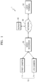
- FIG. 1 is a structural diagram of a network camera system according to an embodiment.
- a network camera system 1 includes a camera 10, a video recorder 20, a network 30, a server 40, and a user terminal 50.
- the camera 10 captures an image of a surveillance area to obtain an original image of the surveillance area.
- the camera 10 may capture an image of a surveillance area in real time for the purpose of surveillance or security.
- the camera 10 may be a PTZ camera capable of panning and tilting and magnification of a zoom lens.
- One or more cameras 10 may be included.
- the network camera system 1 may include a first camera 11 through an nth camera 1n.
- the camera 10 may be a low-power camera driven using a battery.
- a low-power camera maintains a sleep mode in normal situations and wakes up periodically to check whether an event has occurred. When an event has occurred, the low-power camera is converted to an active mode and returns to the sleep mode if no event has occurred. As above, the low-power camera maintains an active mode only when an event occurs, and thus, power consumption may be reduced.
- the camera 10 may communicate with a network device by using various communication methods such as wired or wireless LAN (Local Area Network), Wi-Fi, ZigBee, Bluetooth, Near Field Communication or the like.
- the camera 10 may communicate with a network device according to a low-power communication protocol in which a radio frequency of an ISM band (Industrial Scientific Medical band) is used.
- ISM band Industrial Scientific Medical band
- the video recorder 20 records an original image received from the camera 10, and provides the recorded original image to the server 40 or the user terminal 50 via the network 30.
- the video recorder 20 may mask the original image, and provide the masked image to the server 40 or the user terminal 50 via the network 30.
- the video recorder 20 may additionally provide personal key information of the masked image to the server 40 or the user terminal 50.
- the video recorder 20 may provide personal key information only to the user terminal 50 which has succeeded in authentication.
- the video recorder 20 may provide the masked image to the user terminal 50, and provide personal key information to the server 40.
- the user terminal 50 may receive personal key information of the masked image from the server 40.
- the server 40 may provide personal key information only to the user terminal 50 which has succeeded in authentication.
- the video recorder 20 may be a digital video recorder, a network video recorder or the like, but is not limited thereto.
- the network 30 may include a wired network or a wireless network.
- the wireless network may be, for example, a 2G (Generation) or 3G cellular communication system, a 3GPP (3rd Generation Partnership Project), a 4G communication system, LTE (Long-Term Evolution), WiMAX (World Interoperability for Microwave Access) or the like.
- the server 40 may transmit at least one of the original image, the masked image, and the personal key information received from the video recorder 20 via the network 30, to the user terminal 50.
- the server 40 may periodically receive at least one of the original image, the masked image, and the personal key information, from the video recorder 20.
- the server 40 may periodically transmit at least one of the original image, the masked image, and the personal key information, to the user terminal 50.
- the server 40 may transmit at least one of the original image, the masked image, and the personal key information to the user terminal 50 in response to a user input for requesting an image.
- restoration of a privacy-protected image may be restricted, and thus, security may be tightened.
- a privacy-protected image may be restored without loss, thus enhancing user convenience.
- FIGS. 2A and 2B are structural diagrams of an image processing device according to embodiments.
- a first image processing device 100 includes a first communication interface 110, a first processor 130, and a first memory 150.
- the first communication interface 110 receives an original image from the camera 10.
- the first communication interface 110 may receive a user input for designating a mask area from an external device.
- the external device may be controlled by a business operator or a manager intending to supply a privacy-protected image to the user terminal 50 or the like.
- a user input for designating a mask area may be a user input for selecting coordinates of the mask area or a user input for designating an object.
- the first communication interface 110 may receive an image request from the user terminal 50, and transmit a masked image to the user terminal 50.
- An image request may include at least one of user authentication information and terminal authentication information.
- User authentication information may include at least one of user identification information and a user password.
- Terminal authentication information may include at least one of terminal identification information and a terminal password.
- a masked image refers to an image which a mask area of an original image is processed not to be recognized.
- the first processor 130 determines a mask area of an original image, extracts a switched point among a series of pixels in the mask area, switches, on the basis of the switched point, a first pixel value of a first pixel set and a second pixel value of a second pixel set, and generates a masked image.
- the switched point may be one or more, and the series of pixels sequentially include the first pixel set and the second pixel set.
- the first pixel set includes one or more pixels, and the first pixel value denotes pixel values of the one or more pixels.
- the second pixel set includes one or more pixels, and the second pixel value denotes pixel values of the one or more pixels.
- the first processor 130 may determine a mask area based on a user input for designating a mask area. For example, the first processor 130 may determine a mask area based on coordinates of a mask area selected by a user input.
- the first processor 130 may recognize an object from an original image, and determine a mask area based on the object.
- the object may be a face, a vehicle number or the like.
- the first processor 130 may recognize a face from the original image, and determine an area where the face is displayed, as a mask area.
- the first processor 130 may recognize a vehicle number from an original image, and determine a vehicle number plate area as a mask area.
- a mask area may include a plurality of pixels arranged in a matrix form, and the first processor 130 may rearrange the plurality of pixels to generate a series of pixels.
- the first processor 130 may rearrange a plurality of column lines of a matrix into one line to generate a series of pixels.
- a mask area may include a plurality of lines, and each of the plurality of lines may include a series of pixels, and the number and positions of switched points of the plurality of lines may be independent of each other.
- the first processor 130 may extract a switched point among a series of pixels and switch, on the basis of the switched point, a first pixel value of a first pixel set and a second pixel value of a second pixel set and generate a masked image.
- the plurality of lines may be at least one of a horizontal line, a vertical line, and an oblique line. All of the plurality of lines may be horizontal lines, vertical lines or oblique lines. The plurality of lines may include at least one of a horizontal line, a vertical line, and an oblique line.
- the plurality of lines may include a first line and a second line, and the first processor 130 may generate a masked image by switching a third pixel value of the first line and a fourth pixel value of the second line.
- the first processor 130 may extract a switched point, and switch, on the basis of the switched point, the first pixel value of the first pixel set and the second pixel value of the second pixel set and generate a transformed first line. Also, with respect to the second line, the first processor 130 may extract a switched point, and switch, on the basis of the switched point, the first pixel value of the first pixel set and the second pixel value of the second pixel set and generate a transformed second line. Also, the first processor 130 may switch all pixel values of the transformed first line with all pixel values of the transformed second line to generate a masked image.
- the third pixel value may be a pixel value of a third pixel set which is a partial pixel set of the first line
- the fourth pixel value may be a pixel value of a fourth pixel set which is a partial pixel set of the second line.
- the third pixel set and the fourth pixel set may each include one or more pixels.
- the first processor 130 may extract a switched point, and switch, on the basis of the switched point, the first pixel value of the first pixel set and the second pixel value of the second pixel set and generate a transformed first line. Also, with respect to the second line, the first processor 130 may extract a switched point, and switch, on the basis of the switched point, the first pixel value of the first pixel set and the second pixel value of the second pixel set and generate a transformed second line. Also, the first processor 130 may switch a third pixel value of the third pixel set of the transformed first line and a third pixel value of the third pixel set of the transformed second line to generate a masked image.
- the first processor 130 may additionally transmit information about the switched point to the user terminal 50 via the first communication interface 110 only when user authentication has succeeded based on user authentication information included in an image request or only when terminal authentication has succeeded based on terminal authentication information included in an image request.
- Information about a switched point indicates information needed to restore a masked image.
- the first processor 130 may determine, based on user identification information included in an image request, whether a user indicated by the user identification information is a user entitled to restore a masked image.
- the first processor 130 may identify a user entitled to restore a masked image based on user identification information and a user password included in an image request.
- the first processor 130 may determine whether a terminal indicated by terminal identification information is a terminal which is allowed to restore a masked image, based on terminal identification information included in an image request.
- the first processor 130 may identify a terminal allowed to restore a masked image based on terminal identification information and a terminal password included in an image request.
- a masked image and personal key information may be transmitted only to the user terminal 50 that has succeeded in authentication, and just a masked image may be transmitted to the user terminal 50 which failed in authentication, thus restricting restoration of a privacy-protected and further tightening security.
- the first memory 150 stores a masked image and information about a switched point.
- the first memory 150 may further store an original image.
- the first memory 150 may be a line memory that sequentially stores original images in an order that the images are input. That is, an original image in a matrix form is stored from a first row to a final row in the first memory 150, and each row may be sequentially stored in the first memory 150 from a first column to a last column.
- the first processor 130 may store the original images by switching the pixel values of the original images stored in the first memory 150, on the basis of the switched point, to generate a masked image and store the same in the first memory 150.
- the first processor 130 may match a masked image with information about a switched point and store the matched information in the first memory 150.
- the first image processing device 100 may be implemented as any one physical device or a combination in which a plurality of physical devices are systematically combined.
- the first image processing device 100 may be implemented as the video recorder 20 or the server 40.
- a portion of the first image processing device 100 may be implemented as the video recorder 20, and the other portion thereof may be implemented as the server 40. Meanwhile, the first image processing device 100 may be implemented as a portion of the user terminal 50.
- the second image processing device 200 includes a user interface 210, a second communication interface 230, a second processor 250, a second memory 270, and a display 290.
- the user interface 210 receives a user input.
- a user input received via the user interface 210 may include at least one of user authentication information and terminal authentication information.
- the second communication interface 230 transmits an image request to the video recorder 20, and receives a masked image and personal key information from the video recorder 20.
- An image request may include at least one of user authentication information and terminal authentication information.
- the second processor 250 may perform a mask processing performed by the first processor 130 in a reverse order on the masked image to thereby restore the mask area of the masked image.
- the second processor 250 extracts a switched point from the personal key information, extracts a mask area from the masked image, extracts a series of pixels that sequentially include a first pixel set and a second pixel set from the mask area, and switches a first pixel value of the first pixel set and a second pixel value of the second pixel set on the basis of the switched point to generate a restored image.
- the second processor 250 may restore the mask area by rearranging a series of pixels having switched pixel values, in a matrix form. For example, the second processor 250 may divide one line consisting of a series of pixels having switched pixel values, into n lines respectively including m pixels. Next, the second processor 250 may rearrange the n lines in an order to restore a mask area in an m x n matrix form.
- a mask area may include a plurality of lines, and each of the plurality of lines may include a series of pixels, and the number and positions of switched points of the plurality of lines may be respectively independent of each other.
- the second processor 250 may extract a switched point from personal key information with respect to each of a plurality of lines, and switch, on the basis of the switched point, the first pixel value of the first pixel set and the second pixel value of the second pixel set to generate a restored image.
- the plurality of lines may include a first line and a second line, and the second processor 250 may generate a restored image by switching a third pixel value of the first line and a fourth pixel value of the second line.
- the second processor 250 may extract a switched point, and switch, on the basis of the switched point, the first pixel value of the first pixel set and the second pixel value of the second pixel set to generate a transformed first line. Also, with respect to the second line, the second processor 250 may extract a switched point and switch, on the basis of the switched point, the first pixel value of the first pixel set and the second pixel value of the second pixel set to generate a transformed second line. Also, the second processor 250 may switch all pixel values of the transformed first line with all pixel values of the transformed second line to generate a restored image.
- the third pixel value may be a pixel value of a third pixel set which is a partial pixel set of the first line
- the fourth pixel value may be a pixel value of a fourth pixel set which is a partial pixel set of the second line.
- the second processor 250 may extract a switched point, and switch, on the basis of the switched point, the first pixel value of the first pixel set and the second pixel value of the second pixel set to generate a transformed first line. Also, the second processor 250 may extract, with respect to the second line, a switched point and switch, on the basis of the switched point, the first pixel value of the first pixel set and the second pixel value of the second pixel set to generate a transformed second line. Also, the second processor 250 may switch the third pixel value of the third pixel set of the transformed first line and the third pixel value of the third pixel set of the transformed second line to generate a restored image.
- the second memory 270 stores a masked image, personal key information, a restored image or the like.
- the second memory 270 may be a line memory that sequentially stores masked images in an order that the images are input. That is, a masked image in a matrix form is stored from a first row to a final row in the second memory 270, and each row may be sequentially stored in the second memory 270 from a first column to a last column.
- the second processor 250 may store the masked images by switching the pixel values of the masked images stored in the second memory 270, on the basis of the switched point, to generate a restored image and store the same in the second memory 270.
- the second processor 250 may match a masked image with a restored image and store the matched images in the second memory 270.
- the display 290 displays the masked image or a restored image on a screen.
- the second image processing device 200 may be implemented as any one physical device or a combination in which a plurality of physical devices are systematically combined. Meanwhile, the second image processing device 200 may be implemented as the user terminal 50. A portion of the second image processing device 200 may be implemented as the user terminal 50, and the other portion thereof may be implemented as the video recorder 20 or the server 40.
- FIG. 3 is a flowchart for describing an image processing method according to an embodiment.
- the camera 10 captures an image of a surveillance area (S110).
- the camera 10 captures an image of the surveillance area to generate an original image.
- the video recorder 20 receives an original image from the camera 10 (S120).
- the video recorder 20 may receive, from the camera 10, together with the original image, a capturing time of the original image, information about an event, and camera identification information.
- the video recorder 20 determines a mask area of the original image (S130).
- the video recorder 20 may mask all original images received from the camera 10.
- the video recorder 20 may determine whether to mask an original image based on a capturing time of the original image received from the camera 10. For example, the video recorder 20 may generate a mask image of only original images that are captured at a predetermined time. For example, the video recorder 20 may generate a mask image of only original images that are captured at a time except for a predetermined time.
- the video recorder 20 may determine whether to mask an original image based on information about an event, received from the camera 10. For example, the video recorder 20 may generate a mask image of only original images that are captured in response to a predetermined event. For example, the video recorder 20 may generate a mask image of only original images that are captured in response to events except for a predetermined event.
- the video recorder 20 may determine whether to mask an original image based on a capturing time of the original image received from the camera 10. For example, the video recorder 20 may generate a mask image of only original images that are captured at a predetermined time. For example, the video recorder 20 may generate a mask image of only original images that are captured at a time except for a predetermined time.
- the video recorder 20 may determine whether to mask an original image based on camera identification information received from the camera 10. For example, the video recorder 20 may generate a mask image of only original images that are received from a first camera 11 installed in a predetermined region.
- the video recorder 20 may determine all areas of an original image as a mask area. For example, the video recorder 20 may mask all areas of an original image that is captured in response to a predetermined event. For example, the video recorder 20 may mask all areas of an original image received from the first camera 11 installed in a predetermined region. For example, the video recorder 20 may mask all areas of an original image that are captured at a predetermined time.
- the video recorder 20 may determine a portion of an original image as a mask area.
- a portion of an original image determined as a mask area will be described with reference to FIG. 4 .
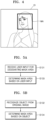
- FIG. 4 is a diagram for describing a mask area according to an embodiment.
- the video recorder 20 may determine a portion of an original image OI received from the camera 10 as a mask area MA.
- a shape of the mask area MA may be a square as illustrated in FIG. 4 , a polygon other than a square, a circle, or a closed curve in various forms such as an outline of an object.
- FIGS. 5A and 5B are flowcharts for describing a mask area determining method according to embodiments.
- the video recorder 20 receives a user input for designating a mask area (S131).
- a user input for designating a mask area may be a user input for selecting coordinates of four vertexes of the mask area MA.
- a user input for designating a mask area may be a user input for selecting each of four vertexes or a user input for selecting one vertex and the other vertex diagonal thereto, but is not limited thereto.
- a user input for designating a mask area may be a user input for selecting any one point within the mask area MA.
- a user input for designating a mask area may be a user input for selecting a predetermined object.
- the user input for designating a mask area may be one or more.
- the video recorder 20 determines a mask area based on a user input (S133).
- the video recorder 20 may determine a mask area MA positioned at coordinates of four vertexes based on a user input for selecting coordinates of four vertexes.
- the video recorder 20 may determine a mask area MA having a predetermined area based on any one point selected by the user input based on the user input for selecting any one point within the mask area MA. For example, the video recorder 20 may determine a mask area MA having an area covering a predetermined face based on a user input for selecting a predetermined face.
- the video recorder 20 recognizes an object from an original image (S132).
- the video recorder 20 may recognize one or more faces or one or more vehicle numbers from an original image.
- the video recorder 20 may recognize one or more predetermined faces or one or more predetermined vehicle numbers from an original image.
- the one or more predetermined faces may indicate predetermined persons.
- the one or more predetermined vehicle numbers may indicate vehicle numbers registered to a predetermined region or vehicle numbers including predetermined numbers.
- the video recorder 20 determines a mask area based on the recognized object (S134).
- the video recorder 20 may determine a mask area MA having an area covering a face. For example, the video recorder 20 may determine one or more mask areas MA covering each of one or more faces displayed on an original image. For example, the video recorder 20 may determine one or more mask areas MA covering faces without glasses from among one or more faces displayed on an original image.
- the video recorder 20 may determine a vehicle number plate area as a mask area MA. For example, the video recorder 20 may determine one or more vehicle number plate areas displayed on an original image as a mask area MA. For example, the video recorder 20 may determine a vehicle number plate area not including predetermined numbers from among the one or more vehicle number plate areas displayed on an original image, as a mask area MA.
- the video recorder 20 extracts a switched point among a series of pixels within the mask area (S140).
- the series of pixels sequentially include a first pixel set and a second pixel set.
- the video recorder 20 generates a masked image by switching a first pixel value of the first pixel set and a second pixel value of the second pixel set on the basis of the switched point (S150).
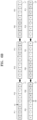
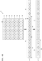
- FIGS. 6A through 6D are diagrams for describing a mask processing method according to embodiments.
- a first line L1 in within a mask area MA of an original image OI may include a series of pixels having pixel values of 0 to 9. That is, a series of pixels of the first line L1 may sequentially include a first pixel set P1 having first pixel values of 0 to 3 and a second pixel set P2 having second pixel values of 4 to 9.
- the video recorder 20 may extract a first switched point H1 among a series of pixels constituting the first line L1 in the mask area MA of the original image Ol.
- the video recorder 20 may generate a masked image by switching the first pixel values of 0 through 3 of the first pixel set P1 and the second pixel values of 4 through 9 of the second pixel set P2 on the basis of the first switched point H1.
- a transformed first line L1' in the mask area MA of a masked image MI may include a series of pixels having pixel values of 4 through 9 and 0 through 3.
- a first line L1 and a second line L2 within a mask area MA of an original image OI may each include a series of pixels having pixel values of 0 to 9. That is, a series of pixels of the first line L1 may sequentially include a first pixel set P11 having first pixel values of 0 to 3 and a second pixel set P12 having second pixel values of 4 to 9. A series of pixels of the second line L2 may sequentially include a first pixel set P21 having first pixel values of 0 to 4 and a second pixel set P22 having second pixel values of 5 to 9.
- the video recorder 20 may extract a first switched point H1, and generate a first transformed first line L1', by switching the first pixel values of 0 through 3 of the first pixel set P11 and the second pixel values of 4 through 9 of the second pixel set P12 on the basis of the first switched point H1.
- the video recorder 20 may extract a second switched point H2, and generate a first transformed second line L2', by switching the first pixel values of 0 through 4 of the first pixel set P21 and the second pixel values of 5 through 9 of the second pixel set P22 on the basis of the second switched point H2.
- the video recorder 20 may generate a masked image by switching all of the pixel values of 4 through 9 and 0 through 3 of the first transformed first line L1' with all of the pixel values of 5 through 9 and 0 through 4 of the first transformed second line L2'.
- a second transformed first line L1", in the mask area MA of the masked image MI may include a series of pixels having pixel values of 5 through 9 and 0 through 4, and a second transformed second line L2", in the mask area MA of the masked image MI may include a series of pixels having pixel values of 4 through 9 and 0 through 3.
- a first line L1 and a second line L2 in a mask area MA of an original image OI may include a series of pixels having pixel values of 0 to 9. That is, a series of pixels of the first line L1 may sequentially include a first pixel set P11 having first pixel values of 0 to 3 and a second pixel set P12 having second pixel values of 4 to 9. A series of pixels of the second line L2 may sequentially include a first pixel set P21 having first pixel values of 0 to 4 and a second pixel set P22 having second pixel values of 5 to 9.
- the video recorder 20 may extract a first switched point H1, and generate a first transformed first line L1', by switching the first pixel values of 0 through 3 of the first pixel set P11 and the second pixel values of 4 through 9 of the second pixel set P12 on the basis of the first switched point H1.
- the video recorder 20 may extract a second switched point H2, and generate a first transformed second line L2', by switching the first pixel values of 0 through 4 of the first pixel set P21 and the second pixel values of 5 through 9 of the second pixel set P22 on the basis of the second switched point H2.
- the video recorder 20 may extract a third switched point H3 among a series of pixels constituting the first transformed first line L1' and a series of pixels constituting the first transformed second line L2'.
- the video recorder 20 may generate a masked image by switching, on the basis of the third switched point H3, the third pixel values of 4 through 9, and 0 of the third pixel set P13 of the first transformed first line L1 and the third pixel values of 5 through 9, 0, and 1 of the third pixel set P23 of the first transformed second line L2'.
- a second transformed first line L1'", in the mask area MA of the masked image MI may include a series of pixels having pixel values of 5 through 9, 0, 1, and 1 through 3, and a second transformed second line L2'", in the mask area MA of the masked image MI may include a series of pixels having pixel values of 4 through 9, 0, and 2 through 4.
- a mask area MA of an original image OI may include a plurality of pixels arranged in a matrix form.
- the video recorder 20 may generate a series of pixels by rearranging the plurality of pixels.
- the video recorder 20 may generate a series of pixels by rearranging first column line R1 through eighth column line R8 of a matrix into a third line L3.
- the video recorder 20 may sequentially list the first column line R1 through the eighth column line R8 to generate a third line L3.
- a series of pixels included in the third line L3 may sequentially include a first pixel set P1 having first pixel values of 10 to 26 and a second pixel set P2 having second pixel values of 27 through 87.
- the video recorder 20 may extract a third switched point H3 among a series of pixels constituting the third line L3 in the mask area MA of the original image Ol.
- the video recorder 20 may generate a masked image by switching the first pixel values of 10 through 26 of the first pixel set P1 and the second pixel values of 27 through 87 of the second pixel set P2 on the basis of the third switched point H3.
- a transformed third line L3' in the mask area MA of a masked image MI may include a series of pixels having pixels values of 27 through 87 and 10 through 26.
- FIG. 7 is a diagram for describing a masked image according to an embodiment.
- the mask area MA of the masked image MI may be masked such that a corresponding area of the original image OI is not recognizable.
- An image request may include at least one of user authentication information and terminal authentication information.
- the video recorder 20 transmits a masked image to the user terminal 50 (S170).
- the video recorder 20 may transmit a masked image to the user terminal 50 in response to the image request.
- the user terminal 50 displays the masked image on a screen (S180).
- the network camera system 1 may enhance security by displaying a privacy-protected image by using the user terminal 50.
- the video recorder 20 determines whether authentication has succeeded based on the image request (S210). Authentication may include at least one of user authentication and terminal authentication.
- the video recorder 20 transmits personal key information including information about a switched point, to the user terminal 50 only when authentication has succeeded (S220).
- the user terminal 50 may extract a switched point from the personal key information (S230), extract a mask area from the masked image (S240), extract a series of pixels that sequentially include a first pixel set and a second pixel set from the mask area (S250), and generate a restored image by switching a first pixel value of the first pixel set and a second pixel value of the second pixel set on the basis of the switched point (S260).
- the user terminal 50 displays a restored image on the screen (S270).
- the network camera system 1 may restore a privacy-protected image by using the user terminal 50 without loss, and thus may enhance user convenience.
- the network camera system 1 may enhance security by restricting restoration of a privacy-protected image by using the user terminal 50.
- the present disclosure is likely to be used in image processing systems of various forms.
Landscapes
- Engineering & Computer Science (AREA)
- Signal Processing (AREA)
- Physics & Mathematics (AREA)
- General Physics & Mathematics (AREA)
- Theoretical Computer Science (AREA)
- Multimedia (AREA)
- Computer Vision & Pattern Recognition (AREA)
- Computer Networks & Wireless Communication (AREA)
- Computer Security & Cryptography (AREA)
- General Engineering & Computer Science (AREA)
- Computing Systems (AREA)
- Computer Hardware Design (AREA)
- Power Engineering (AREA)
- Health & Medical Sciences (AREA)
- General Health & Medical Sciences (AREA)
- Oral & Maxillofacial Surgery (AREA)
- Human Computer Interaction (AREA)
- Closed-Circuit Television Systems (AREA)
- Studio Devices (AREA)
- Image Processing (AREA)
Description
- The present disclosure relates to an image processing device and method.
- These days, numerous surveillance cameras have been installed inside or outside a building or on the street for various purposes such as crime prevention and security. The surveillance cameras may be connected to a server in a wired or wireless manner via a network, and the connected multiple cameras may also be simultaneously controlled from the server.
- Image processing devices such as surveillance cameras or servers may capture and store images, and the captured or stored images may be viewed via a monitor or the like. To protect privacy, a mask may be required to prevent certain areas of an image from being displayed on a monitor or the like, and thus, a surveillance camera may also generate a mask to be displayed on an image by image processing.
-
US 7 825 950 B2 discloses an image processing device in which a masking is accomplished by covering a detected objection in a homogenous gray color or in any other color. - Provided is an image processing technique of restoring a privacy-protected image without loss.
- An image processing device according to an embodiment of the present disclosure includes: a communication interface configured to receive an original image from a camera; a processor configured to determine a mask area of the original image, extract a switched point among a series of pixels in the mask area, and switch, on the basis of the switched point, a first pixel value of a first pixel set and a second pixel value of a second pixel set and generate a masked image; and a memory storing the masked image and information about the switched point, wherein the switched point is one or more, and the series of pixels sequentially include the first pixel set and the second pixel set.
- In the present embodiment, the communication interface may receive a user input for designating the mask area, and the processor may determine the mask area based on the user input.
- In the present embodiment, the processor may recognize an object from the original image, and determine the mask area based on the object.
- In the present embodiment, the mask area may include a plurality of pixels arranged in a matrix form, and the first processor may rearrange the plurality of pixels to generate the series of pixels.
- In the present embodiment, mask area may include a plurality of lines, and each of the plurality of lines may include the series of pixels, and the number and positions of switched points of the plurality of lines may be independent of each other.
- In the present embodiment, the plurality of lines may be at least one of a horizontal line, a vertical line, and an oblique line.
- In the present embodiment, the plurality of lines may include a first line and a second line, and the first processor may generate the masked image by switching a third pixel value of the first line and a fourth pixel value of the second line.
- In the present embodiment, the third pixel value may be a pixel value of a third pixel set which is a partial pixel set of the first line, and the fourth pixel value may be a pixel value of a fourth pixel set which is a partial pixel set of the second line.
- In the present embodiment, the communication interface may receive an image request from a user terminal, and transmit the masked image to the user terminal, and the processor may additionally transmit information about the switched point to the user terminal via the communication interface only when user authentication has succeeded based on user authentication information included in the image request or only when terminal authentication has succeeded based on terminal authentication information included in the image request.
- An image processing device according to another embodiment of the present disclosure includes: a communication interface configured to transmit an image request to a video recorder and receive a masked image and personal key information from the video recorder; a processor configured to extract a switched point from the personal key information, extract a mask area from the masked image, extract a series of pixels that sequentially include a first pixel set and a second pixel set from the mask area, and switch a first pixel value of the first pixel set and a second pixel value of the second pixel set on the basis of the switched point to generate a restored image; and a display configured to display the masked image or display the restored image on a screen.
- In the present embodiment, the image request may include at least one of user authentication information and terminal authentication information.
- In the present embodiment, the processor may restore the mask area by rearranging a series of pixels having switched pixel values, in a matrix form.
- In the present embodiment, the plurality of lines may include a plurality of lines including a first line and a second line, and the processor may generate the restored image by switching a third pixel value of the first line and a fourth pixel value of the second line.
- In the present embodiment, the third pixel value may be a pixel value of a third pixel set which is a partial pixel set of the first line, and the fourth pixel value may be a pixel value of a fourth pixel set which is a partial pixel set of the second line.
- An image processing method according to an embodiment of the present disclosure includes: receiving, via a communication interface, an original image from a camera; determining, by using a processor, a mask area of the original image; extracting, by using the processor, a switched point among a series of pixels in the mask area; generating, by using the processor, a masked image by switching a first pixel value of the first pixel set and a second pixel value of the second pixel set on the basis of the switched point; and transmitting, by using the communication interface, the masked image to a user terminal, wherein the series of pixels sequentially include the first pixel set and the second pixel set.
- In the present embodiment, the method may further include receiving, by using the communication interface, a user input for designating the mask area, wherein the determining of the mask area includes determining the mask area based on the user input.
- In the present embodiment, the method may further include recognizing an object from the original image by using the processor, wherein the determining of the mask area includes determining the mask area based on the object.
- In the method according to the present embodiment, the mask area may include a plurality of pixels arranged in a matrix form, and the method may further include generating, by using the processor, the series of pixels by rearranging the plurality of pixels.
- In the present embodiment, the method may further include: receiving, by using the communication interface, an image request from the user terminal; determining, by using the processor, whether authentication has succeeded or not based on the image request; and transmitting, by using the communication interface, information about the switched point to the user terminal only when authentication has succeeded.
- In the present embodiment, the image request may include at least one of user authentication information and terminal authentication information, and the authentication may include at least one of user authentication and terminal authentication.
- According to the embodiments of the present disclosure, a privacy-protected image may be restored without loss, thus enhancing user convenience.
- According to the embodiments of the present disclosure, restoration of a privacy-protected image may be restricted, thus tightening security.
-
-
FIG. 1 is a structural diagram of a network camera system according to an embodiment. -
FIGS. 2A and 2B are structural diagrams of an image processing device according to embodiments. -
FIG. 3 is a flowchart for describing an image processing method according to an embodiment. -
FIG. 4 is a diagram for describing a mask area according to an embodiment. -
FIGS. 5A and 5B are flowcharts for describing a mask area determining method according to embodiments. -
FIGS. 6A through 6D are diagrams for describing a mask processing method according to embodiments. -
FIG. 7 is a diagram for describing a masked image according to an embodiment. - An image processing device according to an embodiment of the present disclosure includes: a communication interface configured to receive an original image from a camera; a processor configured to determine a mask area of the original image, extract a switched point among a series of pixels in the mask area, and switch, on the basis of the switched point, a first pixel value of a first pixel set and a second pixel value of a second pixel set and generate a masked image; and a memory storing the masked image and information about the switched point, wherein the switched point is one or more, and the series of pixels sequentially include the first pixel set and the second pixel set.
- The embodiments of the present disclosure will now be described with reference to the accompanying drawings.
-
FIG. 1 is a structural diagram of a network camera system according to an embodiment. - Referring to
FIG. 1 , anetwork camera system 1 according to an embodiment includes acamera 10, avideo recorder 20, anetwork 30, aserver 40, and auser terminal 50. - The
camera 10 captures an image of a surveillance area to obtain an original image of the surveillance area. Thecamera 10 may capture an image of a surveillance area in real time for the purpose of surveillance or security. Thecamera 10 may be a PTZ camera capable of panning and tilting and magnification of a zoom lens. One ormore cameras 10 may be included. For example, thenetwork camera system 1 may include afirst camera 11 through annth camera 1n. - The
camera 10 may be a low-power camera driven using a battery. A low-power camera maintains a sleep mode in normal situations and wakes up periodically to check whether an event has occurred. When an event has occurred, the low-power camera is converted to an active mode and returns to the sleep mode if no event has occurred. As above, the low-power camera maintains an active mode only when an event occurs, and thus, power consumption may be reduced. - The
camera 10 may communicate with a network device by using various communication methods such as wired or wireless LAN (Local Area Network), Wi-Fi, ZigBee, Bluetooth, Near Field Communication or the like. For example, thecamera 10 may communicate with a network device according to a low-power communication protocol in which a radio frequency of an ISM band (Industrial Scientific Medical band) is used. - The
video recorder 20 records an original image received from thecamera 10, and provides the recorded original image to theserver 40 or theuser terminal 50 via thenetwork 30. - The
video recorder 20 may mask the original image, and provide the masked image to theserver 40 or theuser terminal 50 via thenetwork 30. Here, thevideo recorder 20 may additionally provide personal key information of the masked image to theserver 40 or theuser terminal 50. Thevideo recorder 20 may provide personal key information only to theuser terminal 50 which has succeeded in authentication. - Meanwhile, the
video recorder 20 may provide the masked image to theuser terminal 50, and provide personal key information to theserver 40. Here, theuser terminal 50 may receive personal key information of the masked image from theserver 40. Theserver 40 may provide personal key information only to theuser terminal 50 which has succeeded in authentication. - The
video recorder 20 may be a digital video recorder, a network video recorder or the like, but is not limited thereto. - The
network 30 may include a wired network or a wireless network. The wireless network may be, for example, a 2G (Generation) or 3G cellular communication system, a 3GPP (3rd Generation Partnership Project), a 4G communication system, LTE (Long-Term Evolution), WiMAX (World Interoperability for Microwave Access) or the like. - The
server 40 may transmit at least one of the original image, the masked image, and the personal key information received from thevideo recorder 20 via thenetwork 30, to theuser terminal 50. - The
server 40 may periodically receive at least one of the original image, the masked image, and the personal key information, from thevideo recorder 20. Theserver 40 may periodically transmit at least one of the original image, the masked image, and the personal key information, to theuser terminal 50. - The
server 40 may transmit at least one of the original image, the masked image, and the personal key information to theuser terminal 50 in response to a user input for requesting an image. - The
user terminal 50 may display or store the original image or the masked image received from thevideo recorder 20 or theserver 40. Theuser terminal 50 which has succeeded in authentication may restore the masked image by using the personal key information received from thevideo recorder 20 or theserver 40. - As described above, according to the present disclosure, restoration of a privacy-protected image may be restricted, and thus, security may be tightened.
- Also, a privacy-protected image may be restored without loss, thus enhancing user convenience.
-
FIGS. 2A and 2B are structural diagrams of an image processing device according to embodiments. - Referring to
FIG. 2A , a firstimage processing device 100 includes afirst communication interface 110, afirst processor 130, and afirst memory 150. - The
first communication interface 110 receives an original image from thecamera 10. - The
first communication interface 110 may receive a user input for designating a mask area from an external device. The external device may be controlled by a business operator or a manager intending to supply a privacy-protected image to theuser terminal 50 or the like. A user input for designating a mask area may be a user input for selecting coordinates of the mask area or a user input for designating an object. - The
first communication interface 110 may receive an image request from theuser terminal 50, and transmit a masked image to theuser terminal 50. An image request may include at least one of user authentication information and terminal authentication information. User authentication information may include at least one of user identification information and a user password. Terminal authentication information may include at least one of terminal identification information and a terminal password. A masked image refers to an image which a mask area of an original image is processed not to be recognized. - The
first processor 130 determines a mask area of an original image, extracts a switched point among a series of pixels in the mask area, switches, on the basis of the switched point, a first pixel value of a first pixel set and a second pixel value of a second pixel set, and generates a masked image. The switched point may be one or more, and the series of pixels sequentially include the first pixel set and the second pixel set. - The first pixel set includes one or more pixels, and the first pixel value denotes pixel values of the one or more pixels. The second pixel set includes one or more pixels, and the second pixel value denotes pixel values of the one or more pixels.
- The
first processor 130 may determine a mask area based on a user input for designating a mask area. For example, thefirst processor 130 may determine a mask area based on coordinates of a mask area selected by a user input. - The
first processor 130 may recognize an object from an original image, and determine a mask area based on the object. The object may be a face, a vehicle number or the like. When the object is a face, thefirst processor 130 may recognize a face from the original image, and determine an area where the face is displayed, as a mask area. When the object is a vehicle number, thefirst processor 130 may recognize a vehicle number from an original image, and determine a vehicle number plate area as a mask area. - A mask area may include a plurality of pixels arranged in a matrix form, and the
first processor 130 may rearrange the plurality of pixels to generate a series of pixels. For example, thefirst processor 130 may rearrange a plurality of column lines of a matrix into one line to generate a series of pixels. - A mask area may include a plurality of lines, and each of the plurality of lines may include a series of pixels, and the number and positions of switched points of the plurality of lines may be independent of each other. Here, with respect to each of the plurality of lines, the
first processor 130 may extract a switched point among a series of pixels and switch, on the basis of the switched point, a first pixel value of a first pixel set and a second pixel value of a second pixel set and generate a masked image. - The plurality of lines may be at least one of a horizontal line, a vertical line, and an oblique line. All of the plurality of lines may be horizontal lines, vertical lines or oblique lines. The plurality of lines may include at least one of a horizontal line, a vertical line, and an oblique line.
- The plurality of lines may include a first line and a second line, and the
first processor 130 may generate a masked image by switching a third pixel value of the first line and a fourth pixel value of the second line. - Here, with respect to the first line, the
first processor 130 may extract a switched point, and switch, on the basis of the switched point, the first pixel value of the first pixel set and the second pixel value of the second pixel set and generate a transformed first line. Also, with respect to the second line, thefirst processor 130 may extract a switched point, and switch, on the basis of the switched point, the first pixel value of the first pixel set and the second pixel value of the second pixel set and generate a transformed second line. Also, thefirst processor 130 may switch all pixel values of the transformed first line with all pixel values of the transformed second line to generate a masked image. - Meanwhile, the third pixel value may be a pixel value of a third pixel set which is a partial pixel set of the first line, and the fourth pixel value may be a pixel value of a fourth pixel set which is a partial pixel set of the second line. The third pixel set and the fourth pixel set may each include one or more pixels.
- Here, with respect to the first line, the
first processor 130 may extract a switched point, and switch, on the basis of the switched point, the first pixel value of the first pixel set and the second pixel value of the second pixel set and generate a transformed first line. Also, with respect to the second line, thefirst processor 130 may extract a switched point, and switch, on the basis of the switched point, the first pixel value of the first pixel set and the second pixel value of the second pixel set and generate a transformed second line. Also, thefirst processor 130 may switch a third pixel value of the third pixel set of the transformed first line and a third pixel value of the third pixel set of the transformed second line to generate a masked image. - The
first processor 130 may additionally transmit information about the switched point to theuser terminal 50 via thefirst communication interface 110 only when user authentication has succeeded based on user authentication information included in an image request or only when terminal authentication has succeeded based on terminal authentication information included in an image request. Information about a switched point indicates information needed to restore a masked image. - The
first processor 130 may determine, based on user identification information included in an image request, whether a user indicated by the user identification information is a user entitled to restore a masked image. Thefirst processor 130 may identify a user entitled to restore a masked image based on user identification information and a user password included in an image request. - The
first processor 130 may determine whether a terminal indicated by terminal identification information is a terminal which is allowed to restore a masked image, based on terminal identification information included in an image request. Thefirst processor 130 may identify a terminal allowed to restore a masked image based on terminal identification information and a terminal password included in an image request. - That is, according to the present embodiment, a masked image and personal key information may be transmitted only to the
user terminal 50 that has succeeded in authentication, and just a masked image may be transmitted to theuser terminal 50 which failed in authentication, thus restricting restoration of a privacy-protected and further tightening security. - The
first memory 150 stores a masked image and information about a switched point. Thefirst memory 150 may further store an original image. Thefirst memory 150 may be a line memory that sequentially stores original images in an order that the images are input. That is, an original image in a matrix form is stored from a first row to a final row in thefirst memory 150, and each row may be sequentially stored in thefirst memory 150 from a first column to a last column. - Meanwhile, the
first processor 130 may store the original images by switching the pixel values of the original images stored in thefirst memory 150, on the basis of the switched point, to generate a masked image and store the same in thefirst memory 150. Here, thefirst processor 130 may match a masked image with information about a switched point and store the matched information in thefirst memory 150. - The first
image processing device 100 may be implemented as any one physical device or a combination in which a plurality of physical devices are systematically combined. The firstimage processing device 100 may be implemented as thevideo recorder 20 or theserver 40. A portion of the firstimage processing device 100 may be implemented as thevideo recorder 20, and the other portion thereof may be implemented as theserver 40. Meanwhile, the firstimage processing device 100 may be implemented as a portion of theuser terminal 50. - Referring to
FIG. 2B , the secondimage processing device 200 includes auser interface 210, asecond communication interface 230, asecond processor 250, asecond memory 270, and adisplay 290. - The
user interface 210 receives a user input. A user input received via theuser interface 210 may include at least one of user authentication information and terminal authentication information. - The
second communication interface 230 transmits an image request to thevideo recorder 20, and receives a masked image and personal key information from thevideo recorder 20. An image request may include at least one of user authentication information and terminal authentication information. - The
second processor 250 may perform a mask processing performed by thefirst processor 130 in a reverse order on the masked image to thereby restore the mask area of the masked image. - The
second processor 250 extracts a switched point from the personal key information, extracts a mask area from the masked image, extracts a series of pixels that sequentially include a first pixel set and a second pixel set from the mask area, and switches a first pixel value of the first pixel set and a second pixel value of the second pixel set on the basis of the switched point to generate a restored image. - Here, the
second processor 250 may restore the mask area by rearranging a series of pixels having switched pixel values, in a matrix form. For example, thesecond processor 250 may divide one line consisting of a series of pixels having switched pixel values, into n lines respectively including m pixels. Next, thesecond processor 250 may rearrange the n lines in an order to restore a mask area in an m x n matrix form. - Meanwhile, a mask area may include a plurality of lines, and each of the plurality of lines may include a series of pixels, and the number and positions of switched points of the plurality of lines may be respectively independent of each other. Here, the
second processor 250 may extract a switched point from personal key information with respect to each of a plurality of lines, and switch, on the basis of the switched point, the first pixel value of the first pixel set and the second pixel value of the second pixel set to generate a restored image. - The plurality of lines may include a first line and a second line, and the
second processor 250 may generate a restored image by switching a third pixel value of the first line and a fourth pixel value of the second line. - Here, with respect to the first line, the
second processor 250 may extract a switched point, and switch, on the basis of the switched point, the first pixel value of the first pixel set and the second pixel value of the second pixel set to generate a transformed first line. Also, with respect to the second line, thesecond processor 250 may extract a switched point and switch, on the basis of the switched point, the first pixel value of the first pixel set and the second pixel value of the second pixel set to generate a transformed second line. Also, thesecond processor 250 may switch all pixel values of the transformed first line with all pixel values of the transformed second line to generate a restored image. - Meanwhile, the third pixel value may be a pixel value of a third pixel set which is a partial pixel set of the first line, and the fourth pixel value may be a pixel value of a fourth pixel set which is a partial pixel set of the second line.
- Here, with respect to the first line, the
second processor 250 may extract a switched point, and switch, on the basis of the switched point, the first pixel value of the first pixel set and the second pixel value of the second pixel set to generate a transformed first line. Also, thesecond processor 250 may extract, with respect to the second line, a switched point and switch, on the basis of the switched point, the first pixel value of the first pixel set and the second pixel value of the second pixel set to generate a transformed second line. Also, thesecond processor 250 may switch the third pixel value of the third pixel set of the transformed first line and the third pixel value of the third pixel set of the transformed second line to generate a restored image. - The
second memory 270 stores a masked image, personal key information, a restored image or the like. Thesecond memory 270 may be a line memory that sequentially stores masked images in an order that the images are input. That is, a masked image in a matrix form is stored from a first row to a final row in thesecond memory 270, and each row may be sequentially stored in thesecond memory 270 from a first column to a last column. - Meanwhile, the
second processor 250 may store the masked images by switching the pixel values of the masked images stored in thesecond memory 270, on the basis of the switched point, to generate a restored image and store the same in thesecond memory 270. Here, thesecond processor 250 may match a masked image with a restored image and store the matched images in thesecond memory 270. - The
display 290 displays the masked image or a restored image on a screen. - The second
image processing device 200 may be implemented as any one physical device or a combination in which a plurality of physical devices are systematically combined. Meanwhile, the secondimage processing device 200 may be implemented as theuser terminal 50. A portion of the secondimage processing device 200 may be implemented as theuser terminal 50, and the other portion thereof may be implemented as thevideo recorder 20 or theserver 40. - Hereinafter, an image processing method according to an embodiment will be described in detail with reference to
FIGS. 3 through 7 . -
FIG. 3 is a flowchart for describing an image processing method according to an embodiment. - Referring to
FIG. 3 , thecamera 10 captures an image of a surveillance area (S110). Thecamera 10 captures an image of the surveillance area to generate an original image. - The
video recorder 20 receives an original image from the camera 10 (S120). Here, thevideo recorder 20 may receive, from thecamera 10, together with the original image, a capturing time of the original image, information about an event, and camera identification information. - Next, the
video recorder 20 determines a mask area of the original image (S130). - The
video recorder 20 may mask all original images received from thecamera 10. - The
video recorder 20 may determine whether to mask an original image based on a capturing time of the original image received from thecamera 10. For example, thevideo recorder 20 may generate a mask image of only original images that are captured at a predetermined time. For example, thevideo recorder 20 may generate a mask image of only original images that are captured at a time except for a predetermined time. - The
video recorder 20 may determine whether to mask an original image based on information about an event, received from thecamera 10. For example, thevideo recorder 20 may generate a mask image of only original images that are captured in response to a predetermined event. For example, thevideo recorder 20 may generate a mask image of only original images that are captured in response to events except for a predetermined event. - The
video recorder 20 may determine whether to mask an original image based on a capturing time of the original image received from thecamera 10. For example, thevideo recorder 20 may generate a mask image of only original images that are captured at a predetermined time. For example, thevideo recorder 20 may generate a mask image of only original images that are captured at a time except for a predetermined time. - The
video recorder 20 may determine whether to mask an original image based on camera identification information received from thecamera 10. For example, thevideo recorder 20 may generate a mask image of only original images that are received from afirst camera 11 installed in a predetermined region. - The
video recorder 20 may determine all areas of an original image as a mask area. For example, thevideo recorder 20 may mask all areas of an original image that is captured in response to a predetermined event. For example, thevideo recorder 20 may mask all areas of an original image received from thefirst camera 11 installed in a predetermined region. For example, thevideo recorder 20 may mask all areas of an original image that are captured at a predetermined time. - The
video recorder 20 may determine a portion of an original image as a mask area. Hereinafter, a portion of an original image determined as a mask area will be described with reference toFIG. 4 . -
FIG. 4 is a diagram for describing a mask area according to an embodiment. - Referring to
FIG. 4 , thevideo recorder 20 may determine a portion of an original image OI received from thecamera 10 as a mask area MA. - A shape of the mask area MA may be a square as illustrated in
FIG. 4 , a polygon other than a square, a circle, or a closed curve in various forms such as an outline of an object. - Hereinafter, a method of determining a mask area will be described with reference to
FIGS. 5A and 5B . -
FIGS. 5A and 5B are flowcharts for describing a mask area determining method according to embodiments. - Referring to
FIG. 5A , thevideo recorder 20 receives a user input for designating a mask area (S131). - A user input for designating a mask area may be a user input for selecting coordinates of four vertexes of the mask area MA. For example, a user input for designating a mask area may be a user input for selecting each of four vertexes or a user input for selecting one vertex and the other vertex diagonal thereto, but is not limited thereto.
- A user input for designating a mask area may be a user input for selecting any one point within the mask area MA. For example, a user input for designating a mask area may be a user input for selecting a predetermined object.
- The user input for designating a mask area may be one or more.
- Meanwhile, the
video recorder 20 determines a mask area based on a user input (S133). - The
video recorder 20 may determine a mask area MA positioned at coordinates of four vertexes based on a user input for selecting coordinates of four vertexes. - The
video recorder 20 may determine a mask area MA having a predetermined area based on any one point selected by the user input based on the user input for selecting any one point within the mask area MA. For example, thevideo recorder 20 may determine a mask area MA having an area covering a predetermined face based on a user input for selecting a predetermined face. - Referring to
FIG. 5B , thevideo recorder 20 recognizes an object from an original image (S132). - The
video recorder 20 may recognize one or more faces or one or more vehicle numbers from an original image. - The
video recorder 20 may recognize one or more predetermined faces or one or more predetermined vehicle numbers from an original image. The one or more predetermined faces may indicate predetermined persons. The one or more predetermined vehicle numbers may indicate vehicle numbers registered to a predetermined region or vehicle numbers including predetermined numbers. - Next, the
video recorder 20 determines a mask area based on the recognized object (S134). - The
video recorder 20 may determine a mask area MA having an area covering a face. For example, thevideo recorder 20 may determine one or more mask areas MA covering each of one or more faces displayed on an original image. For example, thevideo recorder 20 may determine one or more mask areas MA covering faces without glasses from among one or more faces displayed on an original image. - The
video recorder 20 may determine a vehicle number plate area as a mask area MA. For example, thevideo recorder 20 may determine one or more vehicle number plate areas displayed on an original image as a mask area MA. For example, thevideo recorder 20 may determine a vehicle number plate area not including predetermined numbers from among the one or more vehicle number plate areas displayed on an original image, as a mask area MA. - Referring back to
FIG. 3 , thevideo recorder 20 extracts a switched point among a series of pixels within the mask area (S140). The series of pixels sequentially include a first pixel set and a second pixel set. - Next, the
video recorder 20 generates a masked image by switching a first pixel value of the first pixel set and a second pixel value of the second pixel set on the basis of the switched point (S150). - Hereinafter, a method of generating a masked image will be described in detail with reference to
FIGS. 6A through 6D . -
FIGS. 6A through 6D are diagrams for describing a mask processing method according to embodiments. - Referring to
FIG. 6A , for example, a first line L1 in within a mask area MA of an original image OI may include a series of pixels having pixel values of 0 to 9. That is, a series of pixels of the first line L1 may sequentially include a first pixel set P1 having first pixel values of 0 to 3 and a second pixel set P2 having second pixel values of 4 to 9. - The
video recorder 20 may extract a first switched point H1 among a series of pixels constituting the first line L1 in the mask area MA of the original image Ol. - The
video recorder 20 may generate a masked image by switching the first pixel values of 0 through 3 of the first pixel set P1 and the second pixel values of 4 through 9 of the second pixel set P2 on the basis of the first switched point H1. - Accordingly, a transformed first line L1' in the mask area MA of a masked image MI may include a series of pixels having pixel values of 4 through 9 and 0 through 3.
- Referring to
FIG. 6B , for example, a first line L1 and a second line L2 within a mask area MA of an original image OI may each include a series of pixels having pixel values of 0 to 9. That is, a series of pixels of the first line L1 may sequentially include a first pixel set P11 having first pixel values of 0 to 3 and a second pixel set P12 having second pixel values of 4 to 9. A series of pixels of the second line L2 may sequentially include a first pixel set P21 having first pixel values of 0 to 4 and a second pixel set P22 having second pixel values of 5 to 9. - With respect to the first line L1, the
video recorder 20 may extract a first switched point H1, and generate a first transformed first line L1', by switching the first pixel values of 0 through 3 of the first pixel set P11 and the second pixel values of 4 through 9 of the second pixel set P12 on the basis of the first switched point H1. With respect to the second line L2, thevideo recorder 20 may extract a second switched point H2, and generate a first transformed second line L2', by switching the first pixel values of 0 through 4 of the first pixel set P21 and the second pixel values of 5 through 9 of the second pixel set P22 on the basis of the second switched point H2. - Also, the
video recorder 20 may generate a masked image by switching all of the pixel values of 4 through 9 and 0 through 3 of the first transformed first line L1' with all of the pixel values of 5 through 9 and 0 through 4 of the first transformed second line L2'. - Accordingly, a second transformed first line L1", in the mask area MA of the masked image MI may include a series of pixels having pixel values of 5 through 9 and 0 through 4, and a second transformed second line L2", in the mask area MA of the masked image MI may include a series of pixels having pixel values of 4 through 9 and 0 through 3.
- Referring to
FIG. 6C , for example, a first line L1 and a second line L2 in a mask area MA of an original image OI may include a series of pixels having pixel values of 0 to 9. That is, a series of pixels of the first line L1 may sequentially include a first pixel set P11 having first pixel values of 0 to 3 and a second pixel set P12 having second pixel values of 4 to 9. A series of pixels of the second line L2 may sequentially include a first pixel set P21 having first pixel values of 0 to 4 and a second pixel set P22 having second pixel values of 5 to 9. - With respect to the first line L1, the
video recorder 20 may extract a first switched point H1, and generate a first transformed first line L1', by switching the first pixel values of 0 through 3 of the first pixel set P11 and the second pixel values of 4 through 9 of the second pixel set P12 on the basis of the first switched point H1. With respect to the second line L2, thevideo recorder 20 may extract a second switched point H2, and generate a first transformed second line L2', by switching the first pixel values of 0 through 4 of the first pixel set P21 and the second pixel values of 5 through 9 of the second pixel set P22 on the basis of the second switched point H2. - Also, the
video recorder 20 may extract a third switched point H3 among a series of pixels constituting the first transformed first line L1' and a series of pixels constituting the first transformed second line L2'. - The
video recorder 20 may generate a masked image by switching, on the basis of the third switched point H3, the third pixel values of 4 through 9, and 0 of the third pixel set P13 of the first transformed first line L1 and the third pixel values of 5 through 9, 0, and 1 of the third pixel set P23 of the first transformed second line L2'. - Accordingly, a second transformed first line L1'", in the mask area MA of the masked image MI may include a series of pixels having pixel values of 5 through 9, 0, 1, and 1 through 3, and a second transformed second line L2'", in the mask area MA of the masked image MI may include a series of pixels having pixel values of 4 through 9, 0, and 2 through 4.
- Referring to
FIG. 6D , for example, a mask area MA of an original image OI may include a plurality of pixels arranged in a matrix form. - The
video recorder 20 may generate a series of pixels by rearranging the plurality of pixels. For example, thevideo recorder 20 may generate a series of pixels by rearranging first column line R1 through eighth column line R8 of a matrix into a third line L3. Here, thevideo recorder 20 may sequentially list the first column line R1 through the eighth column line R8 to generate a third line L3. A series of pixels included in the third line L3 may sequentially include a first pixel set P1 having first pixel values of 10 to 26 and a second pixel set P2 having second pixel values of 27 through 87. - The
video recorder 20 may extract a third switched point H3 among a series of pixels constituting the third line L3 in the mask area MA of the original image Ol. - The
video recorder 20 may generate a masked image by switching the first pixel values of 10 through 26 of the first pixel set P1 and the second pixel values of 27 through 87 of the second pixel set P2 on the basis of the third switched point H3. - Accordingly, a transformed third line L3' in the mask area MA of a masked image MI may include a series of pixels having pixels values of 27 through 87 and 10 through 26.
- Hereinafter, a masked area will be described with reference to
FIG. 7 . -
FIG. 7 is a diagram for describing a masked image according to an embodiment. - Referring to
FIG. 7 , the mask area MA of the masked image MI according to the present embodiments may be masked such that a corresponding area of the original image OI is not recognizable. - Referring back to
FIG. 3 , thevideo recorder 20 receives an image request from the user terminal 50 (S160). An image request may include at least one of user authentication information and terminal authentication information. - Next, the
video recorder 20 transmits a masked image to the user terminal 50 (S170). Thevideo recorder 20 may transmit a masked image to theuser terminal 50 in response to the image request. - The
user terminal 50 displays the masked image on a screen (S180). - As above, the
network camera system 1 according to the present embodiment may enhance security by displaying a privacy-protected image by using theuser terminal 50. - Meanwhile, the
video recorder 20 determines whether authentication has succeeded based on the image request (S210). Authentication may include at least one of user authentication and terminal authentication. - The
video recorder 20 transmits personal key information including information about a switched point, to theuser terminal 50 only when authentication has succeeded (S220). - The
user terminal 50 may extract a switched point from the personal key information (S230), extract a mask area from the masked image (S240), extract a series of pixels that sequentially include a first pixel set and a second pixel set from the mask area (S250), and generate a restored image by switching a first pixel value of the first pixel set and a second pixel value of the second pixel set on the basis of the switched point (S260). - The
user terminal 50 displays a restored image on the screen (S270). - As above, the
network camera system 1 according to the present embodiment may restore a privacy-protected image by using theuser terminal 50 without loss, and thus may enhance user convenience. - Also, the
network camera system 1 according to the present embodiment may enhance security by restricting restoration of a privacy-protected image by using theuser terminal 50. - While the present disclosure has been particularly shown and described with reference to embodiments thereof, it will be understood by those of ordinary skill in the art that various changes in form and details may be made therein without departing from the scope of the present disclosure as defined by the appended claims.
- The present disclosure is likely to be used in image processing systems of various forms.
Claims (15)
- An image processing device comprising:a communication interface (110) configured to receive an original image from a camera;a processor (130) configured to determine a mask area of the original image, extract a switched point among a series of pixels in the mask area, and switch, on the basis of the switched point, a first pixel value of a first pixel set and a second pixel value of a second pixel set and generate a masked image; anda memory (150) storing the masked image and information about the switched point,wherein the switched point is one or more,the series of pixels sequentially comprise the first pixel set and the second pixel set, andthe image processing device is a video recorder (20).
- The image processing device of claim 1, wherein the communication interface (110) is configured to receive a user input for designating the mask area, and
the processor (130) is configured to determine the mask area based on the user input. - The image processing device of claim 1, the processor (130) is configured to recognize an object from the original image, and to determine the mask area based on the object.
- The image processing device of claim 1, wherein the mask area comprises a plurality of pixels arranged in a matrix form, and
the processor (130) is configured to generate the series of pixels by rearranging the plurality of pixels. - The image processing device of claim 1, wherein the mask area comprises a plurality of lines,the plurality of lines each comprise the series of pixels, andthe number and positions of the switched points of the plurality of lines are respectively independent of each other.
- The image processing device of claim 5, wherein the plurality of lines comprise at least one of a horizontal line, a vertical line, and an oblique line.
- The image processing device of claim 5, wherein the plurality of lines comprise a first line and a second line, and
the processor (130) is configured to generate the masked image by switching a third pixel value of the first line and a fourth pixel value of the second line. - The image processing device of claim 7, wherein the third pixel value comprises a pixel value of a third pixel set which is a partial pixel set of the first line, and
the fourth pixel value comprises a pixel value of a fourth pixel set which is a partial pixel set of the second line. - The image processing device of claim 1, wherein the communication interface (110) is configured to receive an image request from a user terminal, and transmit the masked image to a user terminal, and
the processor (130) is configured to additionally transmit information about the switched point to a user terminal via the communication interface (110) only when user authentication has succeeded based on user authentication information included in an image request from a user terminal or only when terminal authentication has succeeded based on terminal authentication information included in an image request from a user terminal. - An image processing device comprising:a communication interface (230) configured to transmit an image request to a video recorder and receive a masked image and personal key information from a video recorder;a processor (250) configured to extract a switched point from a personal key information of a video recorder, extract a mask area from a masked image of a video recorder, extract a series of pixels that sequentially include a first pixel set and a second pixel set from the mask area, and switch a first pixel value of the first pixel set and a second pixel value of the second pixel set on the basis of the switched point to generate a restored image; anda display (290) configured to display the masked image or display the restored image on a screen,wherein the image processing device is a user terminal (50).
- The image processing device of claim 10, wherein the image request comprises at least one of user authentication information and terminal authentication information.
- The image processing device of claim 10, wherein the processor (250) is configured to restore the mask area by rearranging a series of pixels having switched pixel values, in a matrix form.
- The image processing device of claim 10, wherein the mask area comprises a plurality of lines including a first line and a second line, and
the processor (250) is generate a restored image by switching a third pixel value of the first line and a fourth pixel value of the second line. - The image processing device of claim 13, wherein the third pixel value comprises a pixel value of a third pixel set which is a partial pixel set of the first line, and
wherein the fourth pixel value comprises a pixel value of a fourth pixel set which is a partial pixel set of the second line. - An image processing method, the image processing method comprising:receiving, via a communication interface (110), an original image from a camera;determining, by using a processor (130), a mask area of the original image;extracting, by using the processor, a switched point among a series of pixels in the mask area;generating, by using the processor (130), a masked image by switching a first pixel value of the first pixel set and a second pixel value of the second pixel set on the basis of the switched point; andtransmitting, by using the communication interface (110), the masked image to a user terminal,wherein the series of pixels sequentially comprise the first pixel set and the second pixel set.
Applications Claiming Priority (2)
| Application Number | Priority Date | Filing Date | Title |
|---|---|---|---|
| KR1020160162925A KR102561306B1 (en) | 2016-12-01 | 2016-12-01 | Apparatus and method for processing image |
| PCT/KR2016/015484 WO2018101533A1 (en) | 2016-12-01 | 2016-12-29 | Image processing device and method |
Publications (3)
| Publication Number | Publication Date |
|---|---|
| EP3550505A1 EP3550505A1 (en) | 2019-10-09 |
| EP3550505A4 EP3550505A4 (en) | 2020-06-10 |
| EP3550505B1 true EP3550505B1 (en) | 2024-12-04 |
Family
ID=62242172
Family Applications (1)
| Application Number | Title | Priority Date | Filing Date |
|---|---|---|---|
| EP16922826.9A Active EP3550505B1 (en) | 2016-12-01 | 2016-12-29 | Image processing device and method |
Country Status (5)
| Country | Link |
|---|---|
| US (1) | US10805527B2 (en) |
| EP (1) | EP3550505B1 (en) |
| KR (1) | KR102561306B1 (en) |
| CN (1) | CN110023987B (en) |
| WO (1) | WO2018101533A1 (en) |
Families Citing this family (6)
| Publication number | Priority date | Publication date | Assignee | Title |
|---|---|---|---|---|
| CN109712092B (en) * | 2018-12-18 | 2021-01-05 | 上海信联信息发展股份有限公司 | File scanning image restoration method, device and electronic device |
| US12001572B2 (en) * | 2019-05-13 | 2024-06-04 | Snap One, Llc | Systems and methods for generating artificial automation data to protect actual automation data |
| CN110503114B (en) * | 2019-08-29 | 2023-04-07 | 中国科学院深圳先进技术研究院 | Image feature extraction method, image feature extraction device, tumor recognition system and storage medium |
| CN111866600B (en) * | 2020-06-10 | 2021-10-15 | 北京沃东天骏信息技术有限公司 | Method, apparatus and system for protecting privacy |
| KR102454677B1 (en) * | 2021-01-25 | 2022-10-17 | 주식회사 노타 | Encryption key-based video personal information de-identification and restoration technology |
| WO2025154857A1 (en) * | 2024-01-19 | 2025-07-24 | ㈜와토시스 | System and method for managing de-identified image data of personal information |
Family Cites Families (23)
| Publication number | Priority date | Publication date | Assignee | Title |
|---|---|---|---|---|
| KR930011731A (en) | 1991-11-28 | 1993-06-24 | 이헌조 | Digital Video Scrambling Circuit |
| JPH0765148A (en) * | 1993-08-26 | 1995-03-10 | Matsushita Electric Ind Co Ltd | Image processing method |
| JPH10105681A (en) * | 1996-09-27 | 1998-04-24 | Dainippon Printing Co Ltd | Image processing method |
| JPH1119066A (en) * | 1997-07-08 | 1999-01-26 | Shimadzu Corp | Medical image processing equipment |
| JP2003108994A (en) * | 2001-09-28 | 2003-04-11 | Dainippon Printing Co Ltd | Image creation method and system |
| DE10158990C1 (en) * | 2001-11-30 | 2003-04-10 | Bosch Gmbh Robert | Video surveillance system incorporates masking of identified object for maintaining privacy until entry of authorisation |
| KR100588170B1 (en) | 2003-11-20 | 2006-06-08 | 엘지전자 주식회사 | How to Set Privacy Masking in Surveillance Cameras |
| JP4402998B2 (en) | 2004-03-29 | 2010-01-20 | 三菱電機株式会社 | Surveillance system and camera with masking function, and mask release device used with the camera |
| US8212872B2 (en) * | 2004-06-02 | 2012-07-03 | Robert Bosch Gmbh | Transformable privacy mask for video camera images |
| KR100664350B1 (en) | 2004-12-03 | 2007-01-02 | 엘지전자 주식회사 | Privacy mask display control method |
| US7965268B2 (en) * | 2005-07-08 | 2011-06-21 | Sharp Kabushiki Kaisha | Display device and liquid crystal display panel |
| GB2428152A (en) * | 2005-07-08 | 2007-01-17 | Sharp Kk | Processing image data for direction dependent viewing on a display device |
| KR101598409B1 (en) | 2009-06-17 | 2016-03-02 | 삼성전자주식회사 | Content encryption method, content decryption method, and electronic device using the same |
| KR101378295B1 (en) | 2009-12-18 | 2014-03-27 | 한국전자통신연구원 | Method and Apparatus of privacy masking on Image |
| KR101204093B1 (en) * | 2010-10-05 | 2012-11-22 | 삼성테크윈 주식회사 | Image processing apparatus and controlling method of the same |
| KR20120035299A (en) | 2010-10-05 | 2012-04-16 | 한국인터넷진흥원 | Image protection processing apparatus for privacy protection, and image security system and method using the same |
| JP6209962B2 (en) * | 2013-12-11 | 2017-10-11 | 富士ゼロックス株式会社 | Information processing apparatus and information processing program |
| KR101458136B1 (en) * | 2014-02-28 | 2014-11-05 | 김호 | Video processing method, video processing server performing the same, monitoring server performing the same, system performing the same and storage medium storing the same |
| JP2015170954A (en) * | 2014-03-06 | 2015-09-28 | 学校法人立命館 | ENCRYPTION DEVICE, DECRYPTION DEVICE, SECURITY SYSTEM EQUIPPED WITH THE SAME, PROGRAM EXECUTED BY THEM, AND COMPUTER-READABLE RECORDING MEDIUM CONTAINING THE SAME |
| JP6345961B2 (en) * | 2014-03-28 | 2018-06-20 | 株式会社メガチップス | Image decoding apparatus and image decoding method |
| KR101641646B1 (en) * | 2014-11-28 | 2016-07-21 | 전자부품연구원 | Video masking processing method and apparatus |
| KR101621723B1 (en) * | 2015-02-13 | 2016-05-19 | 경일대학교산학협력단 | Apparatus for processing picture adapted to protect privacy based on face recognition, method thereof and computer recordable medium storing the method |
| US9530231B2 (en) * | 2015-03-05 | 2016-12-27 | Novatek Microelectronics Corp. | Method for generating masking image using general polygonal mask |
-
2016
- 2016-12-01 KR KR1020160162925A patent/KR102561306B1/en active Active
- 2016-12-29 EP EP16922826.9A patent/EP3550505B1/en active Active
- 2016-12-29 WO PCT/KR2016/015484 patent/WO2018101533A1/en not_active Ceased
- 2016-12-29 CN CN201680091313.XA patent/CN110023987B/en active Active
- 2016-12-29 US US16/465,427 patent/US10805527B2/en active Active
Also Published As
| Publication number | Publication date |
|---|---|
| US20200007758A1 (en) | 2020-01-02 |
| US10805527B2 (en) | 2020-10-13 |
| KR20180062819A (en) | 2018-06-11 |
| EP3550505A4 (en) | 2020-06-10 |
| KR102561306B1 (en) | 2023-07-31 |
| CN110023987A (en) | 2019-07-16 |
| EP3550505A1 (en) | 2019-10-09 |
| CN110023987B (en) | 2022-11-18 |
| WO2018101533A1 (en) | 2018-06-07 |
Similar Documents
| Publication | Publication Date | Title |
|---|---|---|
| US10805527B2 (en) | Image processing device and method | |
| US10140826B2 (en) | Surveillance system and method of controlling the same | |
| US10937290B2 (en) | Protection of privacy in video monitoring systems | |
| EP3163872B1 (en) | Flow line analysis system, camera device, and flow line analysis method | |
| JP4402998B2 (en) | Surveillance system and camera with masking function, and mask release device used with the camera | |
| US20150244991A1 (en) | Monitoring camera system and control method of monitoring camera system | |
| US9946948B2 (en) | Article delivery system | |
| CN110557603B (en) | Method and device for monitoring moving target and readable storage medium | |
| US20100231734A1 (en) | Multiple resolution video network with context based control | |
| EP3723049B1 (en) | System and method for anonymizing content to protect privacy | |
| US20160119667A1 (en) | Law enforcement real time digital information chain of custody assurance system and method | |
| CN106791708B (en) | A kind of method for processing video frequency and device | |
| KR102596485B1 (en) | Apparatus and method for registering camera | |
| US20180249125A1 (en) | Privacy preserving monitoring | |
| CN106303468A (en) | The warning system of early warning Intelligent Recognition in advance | |
| JP6483414B2 (en) | Image confirmation system and center device | |
| KR101261293B1 (en) | Control system for video security device using smart phone | |
| KR101280353B1 (en) | Event notification system of condition using mobile device | |
| CN110300290B (en) | Teaching monitoring management method, device and system | |
| KR102454920B1 (en) | Surveillance system and operation method thereof | |
| JP2020053768A (en) | Image sensor system, control method, gateway unit and computer program | |
| KR101583598B1 (en) | Camera, service server, system and method for processing high-resolution image | |
| JP2006319879A (en) | Integrated circuit device, microcomputer and surveillance camera system | |
| JP2010263422A (en) | Information processing apparatus, operation method thereof, and program | |
| JP2018098574A (en) | Video surveillance system and surveillance video display method |
Legal Events
| Date | Code | Title | Description |
|---|---|---|---|
| STAA | Information on the status of an ep patent application or granted ep patent |
Free format text: STATUS: THE INTERNATIONAL PUBLICATION HAS BEEN MADE |
|
| PUAI | Public reference made under article 153(3) epc to a published international application that has entered the european phase |
Free format text: ORIGINAL CODE: 0009012 |
|
| STAA | Information on the status of an ep patent application or granted ep patent |
Free format text: STATUS: REQUEST FOR EXAMINATION WAS MADE |
|
| 17P | Request for examination filed |
Effective date: 20190606 |
|
| AK | Designated contracting states |
Kind code of ref document: A1 Designated state(s): AL AT BE BG CH CY CZ DE DK EE ES FI FR GB GR HR HU IE IS IT LI LT LU LV MC MK MT NL NO PL PT RO RS SE SI SK SM TR |
|
| AX | Request for extension of the european patent |
Extension state: BA ME |
|
| DAV | Request for validation of the european patent (deleted) | ||
| DAX | Request for extension of the european patent (deleted) | ||
| A4 | Supplementary search report drawn up and despatched |
Effective date: 20200511 |
|
| RIC1 | Information provided on ipc code assigned before grant |
Ipc: G06T 3/40 20060101AFI20200504BHEP Ipc: G06T 7/11 20170101ALI20200504BHEP Ipc: G06T 7/32 20170101ALI20200504BHEP Ipc: H04N 7/18 20060101ALI20200504BHEP Ipc: G06T 7/33 20170101ALI20200504BHEP |
|
| RAP1 | Party data changed (applicant data changed or rights of an application transferred) |
Owner name: VISIONEXT CO., LTD. Owner name: HANWHA TECHWIN CO., LTD. |
|
| STAA | Information on the status of an ep patent application or granted ep patent |
Free format text: STATUS: EXAMINATION IS IN PROGRESS |
|
| 17Q | First examination report despatched |
Effective date: 20220413 |
|
| RAP3 | Party data changed (applicant data changed or rights of an application transferred) |
Owner name: VISIONEXT CO., LTD. Owner name: HANWHA VISION CO., LTD. |
|
| GRAP | Despatch of communication of intention to grant a patent |
Free format text: ORIGINAL CODE: EPIDOSNIGR1 |
|
| STAA | Information on the status of an ep patent application or granted ep patent |
Free format text: STATUS: GRANT OF PATENT IS INTENDED |
|
| INTG | Intention to grant announced |
Effective date: 20240708 |
|
| GRAS | Grant fee paid |
Free format text: ORIGINAL CODE: EPIDOSNIGR3 |
|
| GRAA | (expected) grant |
Free format text: ORIGINAL CODE: 0009210 |
|
| STAA | Information on the status of an ep patent application or granted ep patent |
Free format text: STATUS: THE PATENT HAS BEEN GRANTED |
|
| RIN1 | Information on inventor provided before grant (corrected) |
Inventor name: PARK, SUN AE |
|
| AK | Designated contracting states |
Kind code of ref document: B1 Designated state(s): AL AT BE BG CH CY CZ DE DK EE ES FI FR GB GR HR HU IE IS IT LI LT LU LV MC MK MT NL NO PL PT RO RS SE SI SK SM TR |
|
| REG | Reference to a national code |
Ref country code: GB Ref legal event code: FG4D |
|
| RIN1 | Information on inventor provided before grant (corrected) |
Inventor name: PARK, SUN AE |
|
| REG | Reference to a national code |
Ref country code: CH Ref legal event code: EP |
|
| REG | Reference to a national code |
Ref country code: DE Ref legal event code: R096 Ref document number: 602016090547 Country of ref document: DE |
|
| REG | Reference to a national code |
Ref country code: IE Ref legal event code: FG4D |
|
| REG | Reference to a national code |
Ref country code: LT Ref legal event code: MG9D |
|
| REG | Reference to a national code |
Ref country code: NL Ref legal event code: MP Effective date: 20241204 |
|
| PG25 | Lapsed in a contracting state [announced via postgrant information from national office to epo] |
Ref country code: HR Free format text: LAPSE BECAUSE OF FAILURE TO SUBMIT A TRANSLATION OF THE DESCRIPTION OR TO PAY THE FEE WITHIN THE PRESCRIBED TIME-LIMIT Effective date: 20241204 |
|
| PG25 | Lapsed in a contracting state [announced via postgrant information from national office to epo] |
Ref country code: FI Free format text: LAPSE BECAUSE OF FAILURE TO SUBMIT A TRANSLATION OF THE DESCRIPTION OR TO PAY THE FEE WITHIN THE PRESCRIBED TIME-LIMIT Effective date: 20241204 |
|
| PG25 | Lapsed in a contracting state [announced via postgrant information from national office to epo] |
Ref country code: BG Free format text: LAPSE BECAUSE OF FAILURE TO SUBMIT A TRANSLATION OF THE DESCRIPTION OR TO PAY THE FEE WITHIN THE PRESCRIBED TIME-LIMIT Effective date: 20241204 |
|
| PG25 | Lapsed in a contracting state [announced via postgrant information from national office to epo] |
Ref country code: ES Free format text: LAPSE BECAUSE OF FAILURE TO SUBMIT A TRANSLATION OF THE DESCRIPTION OR TO PAY THE FEE WITHIN THE PRESCRIBED TIME-LIMIT Effective date: 20241204 |
|
| PG25 | Lapsed in a contracting state [announced via postgrant information from national office to epo] |
Ref country code: NO Free format text: LAPSE BECAUSE OF FAILURE TO SUBMIT A TRANSLATION OF THE DESCRIPTION OR TO PAY THE FEE WITHIN THE PRESCRIBED TIME-LIMIT Effective date: 20250304 |
|
| PG25 | Lapsed in a contracting state [announced via postgrant information from national office to epo] |
Ref country code: LV Free format text: LAPSE BECAUSE OF FAILURE TO SUBMIT A TRANSLATION OF THE DESCRIPTION OR TO PAY THE FEE WITHIN THE PRESCRIBED TIME-LIMIT Effective date: 20241204 Ref country code: GR Free format text: LAPSE BECAUSE OF FAILURE TO SUBMIT A TRANSLATION OF THE DESCRIPTION OR TO PAY THE FEE WITHIN THE PRESCRIBED TIME-LIMIT Effective date: 20250305 |
|
| PG25 | Lapsed in a contracting state [announced via postgrant information from national office to epo] |
Ref country code: RS Free format text: LAPSE BECAUSE OF FAILURE TO SUBMIT A TRANSLATION OF THE DESCRIPTION OR TO PAY THE FEE WITHIN THE PRESCRIBED TIME-LIMIT Effective date: 20250304 |
|
| PG25 | Lapsed in a contracting state [announced via postgrant information from national office to epo] |
Ref country code: NL Free format text: LAPSE BECAUSE OF FAILURE TO SUBMIT A TRANSLATION OF THE DESCRIPTION OR TO PAY THE FEE WITHIN THE PRESCRIBED TIME-LIMIT Effective date: 20241204 |
|
| REG | Reference to a national code |
Ref country code: AT Ref legal event code: MK05 Ref document number: 1748950 Country of ref document: AT Kind code of ref document: T Effective date: 20241204 |
|
| PG25 | Lapsed in a contracting state [announced via postgrant information from national office to epo] |
Ref country code: SM Free format text: LAPSE BECAUSE OF FAILURE TO SUBMIT A TRANSLATION OF THE DESCRIPTION OR TO PAY THE FEE WITHIN THE PRESCRIBED TIME-LIMIT Effective date: 20241204 |
|
| PG25 | Lapsed in a contracting state [announced via postgrant information from national office to epo] |
Ref country code: PL Free format text: LAPSE BECAUSE OF FAILURE TO SUBMIT A TRANSLATION OF THE DESCRIPTION OR TO PAY THE FEE WITHIN THE PRESCRIBED TIME-LIMIT Effective date: 20241204 |
|
| PG25 | Lapsed in a contracting state [announced via postgrant information from national office to epo] |
Ref country code: IS Free format text: LAPSE BECAUSE OF FAILURE TO SUBMIT A TRANSLATION OF THE DESCRIPTION OR TO PAY THE FEE WITHIN THE PRESCRIBED TIME-LIMIT Effective date: 20250404 |
|
| PG25 | Lapsed in a contracting state [announced via postgrant information from national office to epo] |
Ref country code: PT Free format text: LAPSE BECAUSE OF FAILURE TO SUBMIT A TRANSLATION OF THE DESCRIPTION OR TO PAY THE FEE WITHIN THE PRESCRIBED TIME-LIMIT Effective date: 20250404 |
|
| PG25 | Lapsed in a contracting state [announced via postgrant information from national office to epo] |
Ref country code: EE Free format text: LAPSE BECAUSE OF FAILURE TO SUBMIT A TRANSLATION OF THE DESCRIPTION OR TO PAY THE FEE WITHIN THE PRESCRIBED TIME-LIMIT Effective date: 20241204 |
|
| PG25 | Lapsed in a contracting state [announced via postgrant information from national office to epo] |
Ref country code: RO Free format text: LAPSE BECAUSE OF FAILURE TO SUBMIT A TRANSLATION OF THE DESCRIPTION OR TO PAY THE FEE WITHIN THE PRESCRIBED TIME-LIMIT Effective date: 20241204 Ref country code: AT Free format text: LAPSE BECAUSE OF FAILURE TO SUBMIT A TRANSLATION OF THE DESCRIPTION OR TO PAY THE FEE WITHIN THE PRESCRIBED TIME-LIMIT Effective date: 20241204 |
|
| PG25 | Lapsed in a contracting state [announced via postgrant information from national office to epo] |
Ref country code: SK Free format text: LAPSE BECAUSE OF FAILURE TO SUBMIT A TRANSLATION OF THE DESCRIPTION OR TO PAY THE FEE WITHIN THE PRESCRIBED TIME-LIMIT Effective date: 20241204 |
|
| PG25 | Lapsed in a contracting state [announced via postgrant information from national office to epo] |
Ref country code: CZ Free format text: LAPSE BECAUSE OF FAILURE TO SUBMIT A TRANSLATION OF THE DESCRIPTION OR TO PAY THE FEE WITHIN THE PRESCRIBED TIME-LIMIT Effective date: 20241204 |
|
| PG25 | Lapsed in a contracting state [announced via postgrant information from national office to epo] |
Ref country code: IT Free format text: LAPSE BECAUSE OF FAILURE TO SUBMIT A TRANSLATION OF THE DESCRIPTION OR TO PAY THE FEE WITHIN THE PRESCRIBED TIME-LIMIT Effective date: 20241204 |
|
| REG | Reference to a national code |
Ref country code: CH Ref legal event code: PL |
|
| PG25 | Lapsed in a contracting state [announced via postgrant information from national office to epo] |
Ref country code: LU Free format text: LAPSE BECAUSE OF NON-PAYMENT OF DUE FEES Effective date: 20241229 |
|
| REG | Reference to a national code |
Ref country code: DE Ref legal event code: R097 Ref document number: 602016090547 Country of ref document: DE |
|
| PG25 | Lapsed in a contracting state [announced via postgrant information from national office to epo] |
Ref country code: SE Free format text: LAPSE BECAUSE OF FAILURE TO SUBMIT A TRANSLATION OF THE DESCRIPTION OR TO PAY THE FEE WITHIN THE PRESCRIBED TIME-LIMIT Effective date: 20241204 |
|
| PG25 | Lapsed in a contracting state [announced via postgrant information from national office to epo] |
Ref country code: MC Free format text: LAPSE BECAUSE OF FAILURE TO SUBMIT A TRANSLATION OF THE DESCRIPTION OR TO PAY THE FEE WITHIN THE PRESCRIBED TIME-LIMIT Effective date: 20241204 |
|
| REG | Reference to a national code |
Ref country code: BE Ref legal event code: MM Effective date: 20241231 |
|
| PG25 | Lapsed in a contracting state [announced via postgrant information from national office to epo] |
Ref country code: DK Free format text: LAPSE BECAUSE OF FAILURE TO SUBMIT A TRANSLATION OF THE DESCRIPTION OR TO PAY THE FEE WITHIN THE PRESCRIBED TIME-LIMIT Effective date: 20241204 |
|
| PLBE | No opposition filed within time limit |
Free format text: ORIGINAL CODE: 0009261 |
|
| STAA | Information on the status of an ep patent application or granted ep patent |
Free format text: STATUS: NO OPPOSITION FILED WITHIN TIME LIMIT |
|
| PG25 | Lapsed in a contracting state [announced via postgrant information from national office to epo] |
Ref country code: BE Free format text: LAPSE BECAUSE OF NON-PAYMENT OF DUE FEES Effective date: 20241231 |
|
| PG25 | Lapsed in a contracting state [announced via postgrant information from national office to epo] |
Ref country code: CH Free format text: LAPSE BECAUSE OF NON-PAYMENT OF DUE FEES Effective date: 20241231 |
|
| PG25 | Lapsed in a contracting state [announced via postgrant information from national office to epo] |
Ref country code: IE Free format text: LAPSE BECAUSE OF NON-PAYMENT OF DUE FEES Effective date: 20241229 |
|
| 26N | No opposition filed |
Effective date: 20250905 |
|
| PGFP | Annual fee paid to national office [announced via postgrant information from national office to epo] |
Ref country code: DE Payment date: 20251120 Year of fee payment: 10 |
|
| PGFP | Annual fee paid to national office [announced via postgrant information from national office to epo] |
Ref country code: GB Payment date: 20251120 Year of fee payment: 10 |
|
| REG | Reference to a national code |
Ref country code: DE Ref legal event code: R081 Ref document number: 602016090547 Country of ref document: DE Owner name: HANWHA VISION CO., LTD., SEONGNAM-SI, KR Free format text: FORMER OWNERS: HANWHA VISION CO., LTD., SEONGNAM-SI, GYEONGGI-DO, KR; VISIONEXT CO., LTD., SEONGNAM-SI, GYEONGGI-DO, KR |
|
| PGFP | Annual fee paid to national office [announced via postgrant information from national office to epo] |
Ref country code: FR Payment date: 20251125 Year of fee payment: 10 |
|
| REG | Reference to a national code |
Ref country code: GB Ref legal event code: 732E Free format text: REGISTERED BETWEEN 20260102 AND 20260107 |
|
| PG25 | Lapsed in a contracting state [announced via postgrant information from national office to epo] |
Ref country code: CY Free format text: LAPSE BECAUSE OF FAILURE TO SUBMIT A TRANSLATION OF THE DESCRIPTION OR TO PAY THE FEE WITHIN THE PRESCRIBED TIME-LIMIT Effective date: 20241204 |