EP3550402A1 - Method for controlling display of screen of mobile terminal, and mobile terminal - Google Patents
Method for controlling display of screen of mobile terminal, and mobile terminal Download PDFInfo
- Publication number
- EP3550402A1 EP3550402A1 EP17875303.4A EP17875303A EP3550402A1 EP 3550402 A1 EP3550402 A1 EP 3550402A1 EP 17875303 A EP17875303 A EP 17875303A EP 3550402 A1 EP3550402 A1 EP 3550402A1
- Authority
- EP
- European Patent Office
- Prior art keywords
- mobile terminal
- inclination
- interface content
- screen
- inclined state
- Prior art date
- Legal status (The legal status is an assumption and is not a legal conclusion. Google has not performed a legal analysis and makes no representation as to the accuracy of the status listed.)
- Granted
Links
Images




Classifications
-
- G—PHYSICS
- G06—COMPUTING OR CALCULATING; COUNTING
- G06F—ELECTRIC DIGITAL DATA PROCESSING
- G06F3/00—Input arrangements for transferring data to be processed into a form capable of being handled by the computer; Output arrangements for transferring data from processing unit to output unit, e.g. interface arrangements
- G06F3/01—Input arrangements or combined input and output arrangements for interaction between user and computer
- G06F3/03—Arrangements for converting the position or the displacement of a member into a coded form
- G06F3/0304—Detection arrangements using opto-electronic means
- G06F3/0325—Detection arrangements using opto-electronic means using a plurality of light emitters or reflectors or a plurality of detectors forming a reference frame from which to derive the orientation of the object, e.g. by triangulation or on the basis of reference deformation in the picked up image
-
- G—PHYSICS
- G06—COMPUTING OR CALCULATING; COUNTING
- G06F—ELECTRIC DIGITAL DATA PROCESSING
- G06F3/00—Input arrangements for transferring data to be processed into a form capable of being handled by the computer; Output arrangements for transferring data from processing unit to output unit, e.g. interface arrangements
- G06F3/01—Input arrangements or combined input and output arrangements for interaction between user and computer
- G06F3/048—Interaction techniques based on graphical user interfaces [GUI]
- G06F3/0481—Interaction techniques based on graphical user interfaces [GUI] based on specific properties of the displayed interaction object or a metaphor-based environment, e.g. interaction with desktop elements like windows or icons, or assisted by a cursor's changing behaviour or appearance
-
- G—PHYSICS
- G06—COMPUTING OR CALCULATING; COUNTING
- G06F—ELECTRIC DIGITAL DATA PROCESSING
- G06F3/00—Input arrangements for transferring data to be processed into a form capable of being handled by the computer; Output arrangements for transferring data from processing unit to output unit, e.g. interface arrangements
- G06F3/01—Input arrangements or combined input and output arrangements for interaction between user and computer
- G06F3/048—Interaction techniques based on graphical user interfaces [GUI]
- G06F3/0484—Interaction techniques based on graphical user interfaces [GUI] for the control of specific functions or operations, e.g. selecting or manipulating an object, an image or a displayed text element, setting a parameter value or selecting a range
-
- G—PHYSICS
- G06—COMPUTING OR CALCULATING; COUNTING
- G06K—GRAPHICAL DATA READING; PRESENTATION OF DATA; RECORD CARRIERS; HANDLING RECORD CARRIERS
- G06K7/00—Methods or arrangements for sensing record carriers, e.g. for reading patterns
- G06K7/10—Methods or arrangements for sensing record carriers, e.g. for reading patterns by electromagnetic radiation, e.g. optical sensing; by corpuscular radiation
- G06K7/10544—Methods or arrangements for sensing record carriers, e.g. for reading patterns by electromagnetic radiation, e.g. optical sensing; by corpuscular radiation by scanning of the records by radiation in the optical part of the electromagnetic spectrum
- G06K7/10821—Methods or arrangements for sensing record carriers, e.g. for reading patterns by electromagnetic radiation, e.g. optical sensing; by corpuscular radiation by scanning of the records by radiation in the optical part of the electromagnetic spectrum further details of bar or optical code scanning devices
- G06K7/1095—Methods or arrangements for sensing record carriers, e.g. for reading patterns by electromagnetic radiation, e.g. optical sensing; by corpuscular radiation by scanning of the records by radiation in the optical part of the electromagnetic spectrum further details of bar or optical code scanning devices the scanner comprising adaptations for scanning a record carrier that is displayed on a display-screen or the like
-
- G—PHYSICS
- G06—COMPUTING OR CALCULATING; COUNTING
- G06K—GRAPHICAL DATA READING; PRESENTATION OF DATA; RECORD CARRIERS; HANDLING RECORD CARRIERS
- G06K7/00—Methods or arrangements for sensing record carriers, e.g. for reading patterns
- G06K7/10—Methods or arrangements for sensing record carriers, e.g. for reading patterns by electromagnetic radiation, e.g. optical sensing; by corpuscular radiation
- G06K7/14—Methods or arrangements for sensing record carriers, e.g. for reading patterns by electromagnetic radiation, e.g. optical sensing; by corpuscular radiation using light without selection of wavelength, e.g. sensing reflected white light
- G06K7/1404—Methods for optical code recognition
- G06K7/1408—Methods for optical code recognition the method being specifically adapted for the type of code
- G06K7/1413—1D bar codes
-
- G—PHYSICS
- G06—COMPUTING OR CALCULATING; COUNTING
- G06K—GRAPHICAL DATA READING; PRESENTATION OF DATA; RECORD CARRIERS; HANDLING RECORD CARRIERS
- G06K7/00—Methods or arrangements for sensing record carriers, e.g. for reading patterns
- G06K7/10—Methods or arrangements for sensing record carriers, e.g. for reading patterns by electromagnetic radiation, e.g. optical sensing; by corpuscular radiation
- G06K7/14—Methods or arrangements for sensing record carriers, e.g. for reading patterns by electromagnetic radiation, e.g. optical sensing; by corpuscular radiation using light without selection of wavelength, e.g. sensing reflected white light
- G06K7/1404—Methods for optical code recognition
- G06K7/1408—Methods for optical code recognition the method being specifically adapted for the type of code
- G06K7/1417—2D bar codes
-
- G—PHYSICS
- G06—COMPUTING OR CALCULATING; COUNTING
- G06K—GRAPHICAL DATA READING; PRESENTATION OF DATA; RECORD CARRIERS; HANDLING RECORD CARRIERS
- G06K7/00—Methods or arrangements for sensing record carriers, e.g. for reading patterns
- G06K7/10—Methods or arrangements for sensing record carriers, e.g. for reading patterns by electromagnetic radiation, e.g. optical sensing; by corpuscular radiation
- G06K7/14—Methods or arrangements for sensing record carriers, e.g. for reading patterns by electromagnetic radiation, e.g. optical sensing; by corpuscular radiation using light without selection of wavelength, e.g. sensing reflected white light
- G06K7/1404—Methods for optical code recognition
- G06K7/1439—Methods for optical code recognition including a method step for retrieval of the optical code
- G06K7/1456—Methods for optical code recognition including a method step for retrieval of the optical code determining the orientation of the optical code with respect to the reader and correcting therefore
-
- G—PHYSICS
- G09—EDUCATION; CRYPTOGRAPHY; DISPLAY; ADVERTISING; SEALS
- G09G—ARRANGEMENTS OR CIRCUITS FOR CONTROL OF INDICATING DEVICES USING STATIC MEANS TO PRESENT VARIABLE INFORMATION
- G09G5/00—Control arrangements or circuits for visual indicators common to cathode-ray tube indicators and other visual indicators
- G09G5/36—Control arrangements or circuits for visual indicators common to cathode-ray tube indicators and other visual indicators characterised by the display of a graphic pattern, e.g. using an all-points-addressable [APA] memory
- G09G5/38—Control arrangements or circuits for visual indicators common to cathode-ray tube indicators and other visual indicators characterised by the display of a graphic pattern, e.g. using an all-points-addressable [APA] memory with means for controlling the display position
-
- G—PHYSICS
- G09—EDUCATION; CRYPTOGRAPHY; DISPLAY; ADVERTISING; SEALS
- G09G—ARRANGEMENTS OR CIRCUITS FOR CONTROL OF INDICATING DEVICES USING STATIC MEANS TO PRESENT VARIABLE INFORMATION
- G09G2340/00—Aspects of display data processing
- G09G2340/04—Changes in size, position or resolution of an image
- G09G2340/0492—Change of orientation of the displayed image, e.g. upside-down, mirrored
-
- G—PHYSICS
- G09—EDUCATION; CRYPTOGRAPHY; DISPLAY; ADVERTISING; SEALS
- G09G—ARRANGEMENTS OR CIRCUITS FOR CONTROL OF INDICATING DEVICES USING STATIC MEANS TO PRESENT VARIABLE INFORMATION
- G09G3/00—Control arrangements or circuits, of interest only in connection with visual indicators other than cathode-ray tubes
- G09G3/20—Control arrangements or circuits, of interest only in connection with visual indicators other than cathode-ray tubes for presentation of an assembly of a number of characters, e.g. a page, by composing the assembly by combination of individual elements arranged in a matrix no fixed position being assigned to or needed to be assigned to the individual characters or partial characters
-
- H—ELECTRICITY
- H04—ELECTRIC COMMUNICATION TECHNIQUE
- H04M—TELEPHONIC COMMUNICATION
- H04M1/00—Substation equipment, e.g. for use by subscribers
- H04M1/02—Constructional features of telephone sets
- H04M1/0202—Portable telephone sets, e.g. cordless phones, mobile phones or bar type handsets
-
- H—ELECTRICITY
- H04—ELECTRIC COMMUNICATION TECHNIQUE
- H04M—TELEPHONIC COMMUNICATION
- H04M1/00—Substation equipment, e.g. for use by subscribers
- H04M1/72—Mobile telephones; Cordless telephones, i.e. devices for establishing wireless links to base stations without route selection
- H04M1/724—User interfaces specially adapted for cordless or mobile telephones
- H04M1/72403—User interfaces specially adapted for cordless or mobile telephones with means for local support of applications that increase the functionality
Definitions
- the present application relates to the field of computer technologies, and in particular, to a method for controlling display of a screen of a mobile terminal, and a mobile terminal.
- a recognition apparatus when a recognition apparatus is used to recognize interface content on a screen of a mobile terminal, if the interface content has a strict requirement on a recognition angle, a user usually needs to manually repeatedly adjust a recognition angle of the recognition apparatus.
- the code scanning gun when a code scanning gun is used to recognize a barcode on the screen of the mobile terminal, the code scanning gun can recognize the barcode only when the code scanning gun and the barcode face each other and rotation angles of the code scanning gun and the barcode are similar. Therefore, the user needs to manually and repeatedly adjust a recognition angle of the code scanning gun, which affects efficiency of recognizing the interface content, and brings poor experience to the user.
- the present application describes a method for controlling display of a screen of a mobile terminal, and a mobile terminal, to improve efficiency of recognizing interface content.
- a method for controlling display of a screen of a mobile terminal including: detecting, by a mobile terminal, a first beam; determining whether the detected first beam is in an inclined state, where the inclined state indicates that the first beam has an inclination angle that is greater than a first threshold in a predetermined direction, and the predetermined direction is determined based on a display direction of interface content on a screen of the mobile terminal; and when the detected first beam is in the inclined state, adjusting the display direction of the interface content on the screen of the mobile terminal based on the inclined state of the first beam.
- a mobile terminal includes: a detection unit, configured to detect a first beam; a determining unit, configured to determine whether the first beam detected by the detection unit is in an inclined state, where the inclined state indicates that the first beam has an inclination angle that is greater than a first threshold in a predetermined direction, and the predetermined direction is determined based on a display direction of interface content on a screen of the mobile terminal; and an adjustment unit, configured to: when the determining unit determines that the detected first beam is in the inclined state, adjust the display direction of the interface content on the screen of the mobile terminal based on the inclined state of the first beam.
- the mobile terminal can detect whether a beam emitted by a recognition apparatus arrives.
- the mobile terminal can determine whether the detected beam is in an inclined state. Once the mobile terminal detects that the beam is in the inclined state, the mobile terminal can adjust the display direction of the interface content on the screen of the mobile terminal based on the inclined state of the beam. Therefore, efficiency of recognizing the interface content on the screen of the mobile terminal is improved.
- a method for controlling display of a screen of a mobile terminal is applicable to a scenario that a mobile terminal automatically adjusts a display direction of interface content on a screen of the mobile terminal based on an inclined state of a beam emitted by a recognition apparatus.
- the mobile terminal can be a mobile terminal that has a screen, for example, a mobile phone, a tablet, or a personal digital assistant (PDA), and the screen can be a touchscreen.
- the mobile terminal can further have a sensor such as a complementary metal-oxide-semiconductor (CMOS) or a charge coupled device (CCD), so that the mobile terminal can detect a beam by using the previous sensor.
- CMOS complementary metal-oxide-semiconductor
- CCD charge coupled device
- the interface content in the present application can include but is not limited to a barcode image, a two-dimensional code image, etc.
- the interface content can be recognized in a forward direction or a reverse direction, and the forward direction and the reverse direction are two directions with a difference of 180°.
- FIG. 1 is a flowchart illustrating a method for controlling display of a screen of a mobile terminal, according to an implementation of the present application.
- the method can be performed by a mobile terminal. As shown in FIG. 1 , the method can include the following steps.
- Step 110 The mobile terminal detects a first beam.
- the first beam is a beam that can be sensed by a sensor (e.g., a CMOS or a CCD) of the mobile terminal, for example, can be a laser beam, an infrared beam, or a visible beam.
- a type of the first beam can include a circular beam, a bar beam, etc.
- the first beam in the present application can be emitted by a recognition apparatus.
- the recognition apparatus is a code scanning gun
- a first beam emitted by the code scanning gun can be shown in FIG. 2 .
- the first beam is an infrared beam
- a shape of the infrared beam is a bar beam.
- the camera of the mobile terminal can sense the infrared beam, in other words, the mobile terminal can detect the first beam.
- the camera has a function of a sensor (e.g., a CMOS or a CCD).
- Step 120 Determine whether the detected first beam is in an inclined state.
- the inclined state indicates that the first beam has an inclination angle that is greater than a first threshold in a predetermined direction.
- a user can incline the recognition apparatus that emits the first beam.
- the predetermined direction can be determined based on a display direction of interface content on a screen of the mobile terminal.
- the display direction of the interface content can be used as the predetermined direction.
- the display direction of the interface content is the same as the predetermined direction.
- the display direction of the interface content can include an upward direction, a downward direction, a leftward direction, a rightward direction, a left-upward direction, a left-downward direction, a right-upward direction, or a right-downward direction.
- a reference object of the predetermined direction can include one or more of the following: the mobile terminal, a plane on which a touchscreen of the mobile terminal is located, a horizontal plane, a vertical plane, an X-axis and a Y-axis of the horizontal plane, an X-axis and a Y-axis of the vertical plane, an X-axis and a Y-axis of the plane on which the touchscreen of the mobile terminal is located, etc.
- the reference object can be selected and understood based on an actual situation. For other parts related to this in the present specification, references can be made to the description here. Details are omitted here for simplicity.
- the first threshold can be set based on an empirical value.
- the recognition apparatus is a code scanning gun and the interface content is a barcode
- the first threshold can be a maximum angle between the code scanning gun and the barcode when the barcode can be recognized by the code scanning gun.
- a process that the mobile terminal determines whether the detected first beam is in the inclined state can be as follows: The mobile terminal determines an angle between the first beam and the display direction of the interface content on the screen of the mobile terminal, determines whether the angle is greater than the first threshold, and if the angle is greater than the first threshold, determines that the first beam is in the inclined state. It can be understood that when the predetermined direction is the display direction of the interface content, the angle is the inclination angle.
- a characteristic line (namely, a straight line that can be used to represent the first beam) of the first beam detected by the mobile terminal can be first determined, and then the angle between the first beam and the display direction of the interface content on the screen of the mobile terminal is determined based on an angle between the characteristic line and the display direction of the interface content on the screen of the mobile terminal.
- FIG. 3a is used as an example.
- the interface content on the screen of the mobile terminal can be a barcode image, and a is a display direction (namely, a horizontally rightward direction) of the barcode image.
- b is a characteristic line of the first beam, in other words, the first beam does not have a direction.
- ⁇ 1 and ⁇ 2 are angles between the first beam and the display direction of the barcode image. In other words, there are two angles, and the two angles are supplementary angles. It can be seen from FIG. 3a that value ranges of both ⁇ 1 and ⁇ 2 are [0, 180°]. It is worthwhile to note that only when both ⁇ 1 and ⁇ 2 are greater than the first threshold, it can be determined that the first beam is in the inclined state. It can be understood that if either angle ( ⁇ 1 or ⁇ 2) is not greater than the first threshold, the first beam is not in the inclined state.
- Step 130 When the detected first beam is in the inclined state, adjust a display direction of interface content on a screen of the mobile terminal based on the inclined state of the first beam.
- the interface content can include but is not limited to a barcode image, a two-dimensional code image, etc.
- the interface content can be recognized in a forward direction or a reverse direction, and the forward direction and the reverse direction are two directions with a difference of 180°.
- Step 130 can include the following steps.
- Step A Obtain an inclination angle and an inclination direction of the first beam when the detected first beam is in the inclined state.
- the mobile terminal can obtain the inclination angle and the inclination direction of the first beam when determining that the detected first beam is in the inclined state.
- the inclination direction can include an upward inclination direction, a downward inclination direction, a leftward inclination direction, a rightward inclination direction, a left-upward inclination direction, a left-downward inclination direction, a right-upward inclination direction, or a right-downward inclination direction.
- the user can incline upwards, downwards, leftwards, and rightwards the recognition apparatus that emits the first beam, so that the first beam is in the upward, downward, leftward, and rightward inclination directions.
- FIG. 3a is used as an example.
- both ⁇ 1 and ⁇ 2 are greater than the first threshold, it can be determined that the first beam is in the inclined state.
- two inclination angles that can be obtained are ⁇ 1 and ⁇ 2, an inclination direction corresponding to ⁇ 1 is the downward inclination direction, and an inclination direction corresponding to ⁇ 2 is the upward inclination direction.
- the first beam in FIG. 3a is obtained after a beam in the horizontally rightward direction (namely, the display direction of the barcode image) is rotated clockwise by an angle of ⁇ 1, or is obtained after a beam in the horizontally rightward direction (namely, the display direction of the barcode image) is rotated anticlockwise by an angle of ⁇ 2.
- Step B Adjust the display direction of the interface content on the screen of the mobile terminal based on the inclination angle and the corresponding inclination direction.
- Step B can include the following: determining a rotation direction and a rotation angle of the interface content based on the inclination direction and the inclination angle; and rotating the interface content by the determined rotation angle in the determined rotation direction.
- a process of determining the rotation direction and the rotation angle of the interface content based on the inclination direction and the inclination angle can include the following: selecting, from the plurality of inclination angles, a first inclination angle that does not exceed a second threshold; determining the first inclination angle as the rotation angle; and determining that an inclination direction corresponding to the first inclination angle is the rotation direction.
- the first inclination angle that does not exceed the second threshold is an angle that is less than or equal to the second threshold.
- a process of adjusting the display direction of the interface content on the screen of the mobile terminal includes the following: rotating the barcode image by the angle of ⁇ 1 in the downward inclination direction, in other words, rotating the barcode image clockwise by the angle of ⁇ 1, to obtain a display direction of the barcode image shown in FIG. 3b .
- a direction of the first beam is consistent with the display direction of the barcode image. Therefore, it can be convenient for the code scanning gun to recognize the barcode image.
- a process of adjusting the display direction of the interface content on the screen of the mobile terminal includes the following: rotating the barcode image by the angle of ⁇ 4 in the upward inclination direction, in other words, rotating the barcode image anticlockwise by the angle of ⁇ 4, to obtain a display direction of the barcode image shown in FIG. 4b .
- a direction of the first beam is consistent with the display direction of the barcode image. Therefore, it can be convenient for the code scanning gun to recognize the barcode image.
- the predetermined threshold can also be set to another value. Implementations are not limited in the present application.
- a rotation center can be determined before the interface content is rotated by the determined rotation angle in the determined rotation direction.
- the rotation center can be determined based on a reference object of the predetermined direction. For example, when the reference object is the mobile terminal, the plane on which the touchscreen of the mobile terminal is located, the X-axis and the Y-axis of the plane on which the touchscreen of the mobile terminal is located, etc., the determined rotation center can be a center of the screen of the mobile terminal.
- the determined rotation center can be a center of the horizontal plane (namely, an intersection point of the X-axis and the Y-axis of the horizontal plane).
- the determined rotation center can be a center of the vertical plane (namely, an intersection point of the X-axis and the Y-axis of the vertical plane).
- the step of rotating the interface content by the determined rotation angle in the determined rotation direction can be replaced with the following: rotating the interface content by the determined rotation angle in the determined rotation direction by using the determined rotation center as a center.
- the display direction of the interface content on the screen of the mobile terminal may not be adjusted.
- the mobile terminal when the first beam emitted by the recognition apparatus is in the inclined state, the mobile terminal automatically adjusts the display direction of the interface content on the screen of the mobile terminal based on the inclined state of the first beam, so that interface content that has a strict requirement on a recognition angle can be recognized easily, further improving user experience.
- the code scanning gun can read a value of the barcode image only when the code scanning gun and the barcode image face each other and rotation angles of the code scanning gun and the barcode image are similar. Therefore, in the present application, according to a method for automatically adjusting the display direction of the barcode image based on an inclined state of the infrared beam emitted by the code scanning gun, problems of poor user experience that are caused because the user needs to repeatedly adjust a location of the code scanning gun can be alleviated.
- the mobile terminal includes a detection unit 501, a determining unit 502, and an adjustment unit 503.
- the detection unit 501 is configured to detect a first beam.
- the determining unit 502 is configured to determine whether the first beam detected by the detection unit is in an inclined state, where the inclined state indicates that the first beam has an inclination angle that is greater than a first threshold in a predetermined direction, and the predetermined direction is determined based on a display direction of interface content on a screen of the mobile terminal.
- the predetermined direction can include an upward direction, a downward direction, a leftward direction, a rightward direction, a left-upward direction, a left-downward direction, a right-upward direction, or a right-downward direction.
- the adjustment unit 503 is configured to: when the determining unit 502 determines that the detected first beam is in the inclined state, adjust the display direction of the interface content on the screen of the mobile terminal based on the inclined state of the first beam.
- the adjustment unit 503 can be configured to: obtain an inclination angle of the first beam and a corresponding inclination direction based on the inclined state of the first beam; and adjust the display direction of the interface content on the screen of the mobile terminal based on the inclination angle and the corresponding inclination direction.
- the adjustment unit 503 can be further configured to: determine a rotation angle of the interface content and a corresponding rotation direction based on the inclination angle and the corresponding inclination direction; and rotate the interface content by the rotation angle in the determined rotation direction.
- the adjustment unit 503 can be further configured to: select, from the plurality of inclination angles, a first inclination angle that does not exceed a second threshold; determine the first inclination angle as the rotation angle; and determine that an inclination direction corresponding to the first inclination angle is the rotation direction.
- Functions of function modules of the apparatus in the present implementation of the present application can be implemented by performing the steps in the previous method implementation. Therefore, a specific working process of the apparatus provided in the present application is omitted here.
- the detection unit 501 detects the first beam.
- the determining unit 502 determines whether the detected first beam is in the inclined state.
- the adjustment unit 503 adjusts the display direction of the interface content on the screen of the mobile terminal based on the inclined state of the first beam. Therefore, efficiency of recognizing the interface content on the screen of the mobile terminal is improved.
Landscapes
- Engineering & Computer Science (AREA)
- Physics & Mathematics (AREA)
- Theoretical Computer Science (AREA)
- General Physics & Mathematics (AREA)
- General Engineering & Computer Science (AREA)
- Electromagnetism (AREA)
- Toxicology (AREA)
- Computer Vision & Pattern Recognition (AREA)
- Artificial Intelligence (AREA)
- General Health & Medical Sciences (AREA)
- Health & Medical Sciences (AREA)
- Human Computer Interaction (AREA)
- Computer Hardware Design (AREA)
- User Interface Of Digital Computer (AREA)
- Telephone Function (AREA)
- Control Of Indicators Other Than Cathode Ray Tubes (AREA)
- Controls And Circuits For Display Device (AREA)
- Position Input By Displaying (AREA)
- Mobile Radio Communication Systems (AREA)
Abstract
Description
- The present application relates to the field of computer technologies, and in particular, to a method for controlling display of a screen of a mobile terminal, and a mobile terminal.
- In a conventional technology, when a recognition apparatus is used to recognize interface content on a screen of a mobile terminal, if the interface content has a strict requirement on a recognition angle, a user usually needs to manually repeatedly adjust a recognition angle of the recognition apparatus. For example, when a code scanning gun is used to recognize a barcode on the screen of the mobile terminal, the code scanning gun can recognize the barcode only when the code scanning gun and the barcode face each other and rotation angles of the code scanning gun and the barcode are similar. Therefore, the user needs to manually and repeatedly adjust a recognition angle of the code scanning gun, which affects efficiency of recognizing the interface content, and brings poor experience to the user.
- The present application describes a method for controlling display of a screen of a mobile terminal, and a mobile terminal, to improve efficiency of recognizing interface content.
- According to a first aspect, a method for controlling display of a screen of a mobile terminal is provided, including: detecting, by a mobile terminal, a first beam; determining whether the detected first beam is in an inclined state, where the inclined state indicates that the first beam has an inclination angle that is greater than a first threshold in a predetermined direction, and the predetermined direction is determined based on a display direction of interface content on a screen of the mobile terminal; and when the detected first beam is in the inclined state, adjusting the display direction of the interface content on the screen of the mobile terminal based on the inclined state of the first beam.
- According to a second aspect, a mobile terminal is provided, and the mobile terminal includes: a detection unit, configured to detect a first beam; a determining unit, configured to determine whether the first beam detected by the detection unit is in an inclined state, where the inclined state indicates that the first beam has an inclination angle that is greater than a first threshold in a predetermined direction, and the predetermined direction is determined based on a display direction of interface content on a screen of the mobile terminal; and an adjustment unit, configured to: when the determining unit determines that the detected first beam is in the inclined state, adjust the display direction of the interface content on the screen of the mobile terminal based on the inclined state of the first beam.
- According to the method for controlling the display of the screen of the mobile terminal, and the mobile terminal provided in the present application, the mobile terminal can detect whether a beam emitted by a recognition apparatus arrives. When the mobile terminal detects that a beam arrives, the mobile terminal can determine whether the detected beam is in an inclined state. Once the mobile terminal detects that the beam is in the inclined state, the mobile terminal can adjust the display direction of the interface content on the screen of the mobile terminal based on the inclined state of the beam. Therefore, efficiency of recognizing the interface content on the screen of the mobile terminal is improved.
- To describe the technical solutions in the implementations of the present disclosure more clearly, the following briefly describes the accompanying drawings needed for describing the implementations. Apparently, the accompanying drawings in the following description show merely some implementations of the present disclosure, and a person of ordinary skill in the art can still derive other drawings from these accompanying drawings without creative efforts.
-
FIG. 1 is a flowchart illustrating a method for controlling display of a screen of a mobile terminal, according to an implementation of the present application; -
FIG. 2 is a schematic diagram illustrating a first beam, according to the present application; -
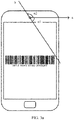
FIG. 3a is a first schematic diagram illustrating an angle between a first beam and interface content, according to the present application; -
FIG. 3b is a first schematic diagram illustrating interface content on a screen of a mobile terminal, according to the present application; -
FIG. 4a is a second schematic diagram illustrating an angle between a first beam and interface content, according to the present application; -
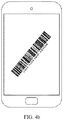
FIG. 4b is a second schematic diagram illustrating interface content on a screen of a mobile terminal, according to the present application; and -
FIG. 5 is a schematic diagram illustrating a mobile terminal, according to an implementation of the present application. - The following describes implementations of the present disclosure with reference to accompanying drawings.
- A method for controlling display of a screen of a mobile terminal provided in the present application is applicable to a scenario that a mobile terminal automatically adjusts a display direction of interface content on a screen of the mobile terminal based on an inclined state of a beam emitted by a recognition apparatus. The mobile terminal can be a mobile terminal that has a screen, for example, a mobile phone, a tablet, or a personal digital assistant (PDA), and the screen can be a touchscreen. In addition, the mobile terminal can further have a sensor such as a complementary metal-oxide-semiconductor (CMOS) or a charge coupled device (CCD), so that the mobile terminal can detect a beam by using the previous sensor. It is worthwhile to note that the interface content in the present application can include but is not limited to a barcode image, a two-dimensional code image, etc. The interface content can be recognized in a forward direction or a reverse direction, and the forward direction and the reverse direction are two directions with a difference of 180°.
-
FIG. 1 is a flowchart illustrating a method for controlling display of a screen of a mobile terminal, according to an implementation of the present application. The method can be performed by a mobile terminal. As shown inFIG. 1 , the method can include the following steps. - Step 110: The mobile terminal detects a first beam.
- The first beam is a beam that can be sensed by a sensor (e.g., a CMOS or a CCD) of the mobile terminal, for example, can be a laser beam, an infrared beam, or a visible beam. A type of the first beam can include a circular beam, a bar beam, etc. It is worthwhile to note that the first beam in the present application can be emitted by a recognition apparatus. For example, when the recognition apparatus is a code scanning gun, a first beam emitted by the code scanning gun can be shown in
FIG. 2 . InFIG. 2 , the first beam is an infrared beam, and a shape of the infrared beam is a bar beam. When the infrared beam emitted by the code scanning gun covers a camera of the mobile terminal, the camera of the mobile terminal can sense the infrared beam, in other words, the mobile terminal can detect the first beam. The camera has a function of a sensor (e.g., a CMOS or a CCD). - Step 120: Determine whether the detected first beam is in an inclined state.
- The inclined state indicates that the first beam has an inclination angle that is greater than a first threshold in a predetermined direction. For example, a user can incline the recognition apparatus that emits the first beam. The predetermined direction can be determined based on a display direction of interface content on a screen of the mobile terminal. In the present application, the display direction of the interface content can be used as the predetermined direction. In other words, the display direction of the interface content is the same as the predetermined direction. The display direction of the interface content can include an upward direction, a downward direction, a leftward direction, a rightward direction, a left-upward direction, a left-downward direction, a right-upward direction, or a right-downward direction. A reference object of the predetermined direction can include one or more of the following: the mobile terminal, a plane on which a touchscreen of the mobile terminal is located, a horizontal plane, a vertical plane, an X-axis and a Y-axis of the horizontal plane, an X-axis and a Y-axis of the vertical plane, an X-axis and a Y-axis of the plane on which the touchscreen of the mobile terminal is located, etc. The reference object can be selected and understood based on an actual situation. For other parts related to this in the present specification, references can be made to the description here. Details are omitted here for simplicity.
- It is worthwhile to note that the first threshold can be set based on an empirical value. For example, when the recognition apparatus is a code scanning gun and the interface content is a barcode, the first threshold can be a maximum angle between the code scanning gun and the barcode when the barcode can be recognized by the code scanning gun.
- In step 120, a process that the mobile terminal determines whether the detected first beam is in the inclined state can be as follows: The mobile terminal determines an angle between the first beam and the display direction of the interface content on the screen of the mobile terminal, determines whether the angle is greater than the first threshold, and if the angle is greater than the first threshold, determines that the first beam is in the inclined state. It can be understood that when the predetermined direction is the display direction of the interface content, the angle is the inclination angle.
- In an implementation, when the first beam is a bar beam, before the previous angle is determined, a characteristic line (namely, a straight line that can be used to represent the first beam) of the first beam detected by the mobile terminal can be first determined, and then the angle between the first beam and the display direction of the interface content on the screen of the mobile terminal is determined based on an angle between the characteristic line and the display direction of the interface content on the screen of the mobile terminal.
FIG. 3a is used as an example. The interface content on the screen of the mobile terminal can be a barcode image, and a is a display direction (namely, a horizontally rightward direction) of the barcode image. In addition, b is a characteristic line of the first beam, in other words, the first beam does not have a direction. Therefore, α1 and α2 are angles between the first beam and the display direction of the barcode image. In other words, there are two angles, and the two angles are supplementary angles. It can be seen fromFIG. 3a that value ranges of both α1 and α2 are [0, 180°]. It is worthwhile to note that only when both α1 and α2 are greater than the first threshold, it can be determined that the first beam is in the inclined state. It can be understood that if either angle (α1 or α2) is not greater than the first threshold, the first beam is not in the inclined state. - Step 130: When the detected first beam is in the inclined state, adjust a display direction of interface content on a screen of the mobile terminal based on the inclined state of the first beam.
- The interface content can include but is not limited to a barcode image, a two-dimensional code image, etc. The interface content can be recognized in a forward direction or a reverse direction, and the forward direction and the reverse direction are two directions with a difference of 180°.
- Step 130 can include the following steps.
- Step A: Obtain an inclination angle and an inclination direction of the first beam when the detected first beam is in the inclined state.
- Specifically, the mobile terminal can obtain the inclination angle and the inclination direction of the first beam when determining that the detected first beam is in the inclined state. The inclination direction can include an upward inclination direction, a downward inclination direction, a leftward inclination direction, a rightward inclination direction, a left-upward inclination direction, a left-downward inclination direction, a right-upward inclination direction, or a right-downward inclination direction. For example, the user can incline upwards, downwards, leftwards, and rightwards the recognition apparatus that emits the first beam, so that the first beam is in the upward, downward, leftward, and rightward inclination directions.
-
FIG. 3a is used as an example. When both α1 and α2 are greater than the first threshold, it can be determined that the first beam is in the inclined state. InFIG. 3a , two inclination angles that can be obtained are α1 and α2, an inclination direction corresponding to α1 is the downward inclination direction, and an inclination direction corresponding to α2 is the upward inclination direction. It can be understood that the first beam inFIG. 3a is obtained after a beam in the horizontally rightward direction (namely, the display direction of the barcode image) is rotated clockwise by an angle of α1, or is obtained after a beam in the horizontally rightward direction (namely, the display direction of the barcode image) is rotated anticlockwise by an angle of α2. - Step B: Adjust the display direction of the interface content on the screen of the mobile terminal based on the inclination angle and the corresponding inclination direction.
- Step B can include the following: determining a rotation direction and a rotation angle of the interface content based on the inclination direction and the inclination angle; and rotating the interface content by the determined rotation angle in the determined rotation direction.
- In an implementation, when a plurality of inclination angles are determined, a process of determining the rotation direction and the rotation angle of the interface content based on the inclination direction and the inclination angle can include the following: selecting, from the plurality of inclination angles, a first inclination angle that does not exceed a second threshold; determining the first inclination angle as the rotation angle; and determining that an inclination direction corresponding to the first inclination angle is the rotation direction. It is worthwhile to note that the first inclination angle that does not exceed the second threshold is an angle that is less than or equal to the second threshold.
- Assume that the second threshold is 90°. In
FIG. 3a , because the inclination angle α1 does not exceed the second threshold, it can be determined that a rotation angle of the barcode image is α1 and a rotation direction of the barcode image is a downward inclination direction, namely, the inclination direction corresponding to α1. Therefore, a process of adjusting the display direction of the interface content on the screen of the mobile terminal includes the following: rotating the barcode image by the angle of α1 in the downward inclination direction, in other words, rotating the barcode image clockwise by the angle of α1, to obtain a display direction of the barcode image shown inFIG. 3b . InFIG. 3b , a direction of the first beam is consistent with the display direction of the barcode image. Therefore, it can be convenient for the code scanning gun to recognize the barcode image. - In another example, when an angle between the first beam and the display direction of the barcode image is shown in
FIG. 4a , and assume that both angles inFIG. 4a are greater than the first threshold, it can be determined that the first beam is in the inclined state. Therefore, two inclination angles α3 and α4 can be obtained, an inclination direction corresponding to α3 is the downward inclination direction, and an inclination direction corresponding to α4 is the upward inclination direction. Because the inclination angle α4 does not exceed the second threshold, it can be determined that a rotation angle of the barcode image is α4, and a rotation direction of the barcode image is the upward inclination direction, namely, the inclination direction corresponding to α4. Therefore, a process of adjusting the display direction of the interface content on the screen of the mobile terminal includes the following: rotating the barcode image by the angle of α4 in the upward inclination direction, in other words, rotating the barcode image anticlockwise by the angle of α4, to obtain a display direction of the barcode image shown inFIG. 4b . InFIG. 4b , a direction of the first beam is consistent with the display direction of the barcode image. Therefore, it can be convenient for the code scanning gun to recognize the barcode image. - Certainly, in practice, the predetermined threshold can also be set to another value. Implementations are not limited in the present application.
- Optionally, a rotation center can be determined before the interface content is rotated by the determined rotation angle in the determined rotation direction. In an example, the rotation center can be determined based on a reference object of the predetermined direction. For example, when the reference object is the mobile terminal, the plane on which the touchscreen of the mobile terminal is located, the X-axis and the Y-axis of the plane on which the touchscreen of the mobile terminal is located, etc., the determined rotation center can be a center of the screen of the mobile terminal. Alternatively, when the reference object is the horizontal plane, the X-axis and the Y-axis of the horizontal plane, etc., the determined rotation center can be a center of the horizontal plane (namely, an intersection point of the X-axis and the Y-axis of the horizontal plane). Alternatively, when the reference object is the vertical plane, the X-axis and the Y-axis of the vertical plane, etc., the determined rotation center can be a center of the vertical plane (namely, an intersection point of the X-axis and the Y-axis of the vertical plane).
- When the rotation center is further determined, the step of rotating the interface content by the determined rotation angle in the determined rotation direction can be replaced with the following: rotating the interface content by the determined rotation angle in the determined rotation direction by using the determined rotation center as a center.
- It is worthwhile to note that when the detected first beam is not in the inclined state, the display direction of the interface content on the screen of the mobile terminal may not be adjusted.
- It can be seen that in the present application, when the first beam emitted by the recognition apparatus is in the inclined state, the mobile terminal automatically adjusts the display direction of the interface content on the screen of the mobile terminal based on the inclined state of the first beam, so that interface content that has a strict requirement on a recognition angle can be recognized easily, further improving user experience.
- When the interface content is a barcode image, the code scanning gun can read a value of the barcode image only when the code scanning gun and the barcode image face each other and rotation angles of the code scanning gun and the barcode image are similar. Therefore, in the present application, according to a method for automatically adjusting the display direction of the barcode image based on an inclined state of the infrared beam emitted by the code scanning gun, problems of poor user experience that are caused because the user needs to repeatedly adjust a location of the code scanning gun can be alleviated.
- Corresponding to the previous method for controlling display of a screen of a mobile terminal, an implementation of the present application further provides a mobile terminal. As shown in
FIG. 5 , the mobile terminal includes adetection unit 501, a determiningunit 502, and anadjustment unit 503. - The
detection unit 501 is configured to detect a first beam. - The determining
unit 502 is configured to determine whether the first beam detected by the detection unit is in an inclined state, where the inclined state indicates that the first beam has an inclination angle that is greater than a first threshold in a predetermined direction, and the predetermined direction is determined based on a display direction of interface content on a screen of the mobile terminal. - The predetermined direction can include an upward direction, a downward direction, a leftward direction, a rightward direction, a left-upward direction, a left-downward direction, a right-upward direction, or a right-downward direction.
- The
adjustment unit 503 is configured to: when the determiningunit 502 determines that the detected first beam is in the inclined state, adjust the display direction of the interface content on the screen of the mobile terminal based on the inclined state of the first beam. - Optionally, the
adjustment unit 503 can be configured to: obtain an inclination angle of the first beam and a corresponding inclination direction based on the inclined state of the first beam; and adjust the display direction of the interface content on the screen of the mobile terminal based on the inclination angle and the corresponding inclination direction. - Optionally, the
adjustment unit 503 can be further configured to: determine a rotation angle of the interface content and a corresponding rotation direction based on the inclination angle and the corresponding inclination direction; and rotate the interface content by the rotation angle in the determined rotation direction. - Optionally, when there are a plurality of inclination angles, the
adjustment unit 503 can be further configured to: select, from the plurality of inclination angles, a first inclination angle that does not exceed a second threshold; determine the first inclination angle as the rotation angle; and determine that an inclination direction corresponding to the first inclination angle is the rotation direction. - Functions of function modules of the apparatus in the present implementation of the present application can be implemented by performing the steps in the previous method implementation. Therefore, a specific working process of the apparatus provided in the present application is omitted here.
- According to the mobile terminal provided in the present application, the
detection unit 501 detects the first beam. The determiningunit 502 determines whether the detected first beam is in the inclined state. When the detected first beam is in the inclined state, theadjustment unit 503 adjusts the display direction of the interface content on the screen of the mobile terminal based on the inclined state of the first beam. Therefore, efficiency of recognizing the interface content on the screen of the mobile terminal is improved. - A person skilled in the art should be aware that in the previous one or more examples, functions described in the present disclosure can be implemented by hardware, software, firmware, or any combination thereof. When the functions are implemented by software, the functions can be stored in a computer readable medium or transmitted as one or more instructions or code in the computer readable medium.
- The objectives, technical solutions, and benefits of the present disclosure are further described in detail in the previous specific implementations. It should be understood that the previous descriptions are merely specific implementations of the present disclosure, but are not intended to limit the protection scope of the present disclosure. Any modification, equivalent replacement, improvement, etc. made based on the technical solutions of the present disclosure shall fall within the protection scope of the present disclosure.
Claims (10)
- A method for controlling display of a screen of a mobile terminal, comprising:detecting, by a mobile terminal, a first beam;determining whether the detected first beam is in an inclined state, wherein the inclined state indicates that the first beam has an inclination angle that is greater than a first threshold in a predetermined direction, and wherein the predetermined direction is determined based on a display direction of interface content on a screen of the mobile terminal; andin response to determining that the detected first beam is in the inclined state, adjusting the display direction of the interface content on the screen of the mobile terminal based on the inclined state of the first beam.
- The method according to claim 1, wherein the adjusting the display direction of the interface content on the screen of the mobile terminal based on the inclined state of the first beam comprises:obtaining an inclination angle of the first beam and a corresponding inclination direction based on the inclined state of the first beam; andadjusting the display direction of the interface content on the screen of the mobile terminal based on the inclination angle and the corresponding inclination direction.
- The method according to claim 2, wherein the adjusting the display direction of the interface content on the screen of the mobile terminal based on the inclination angle and the inclination direction comprises:determining a rotation angle of the interface content and a corresponding rotation direction based on the inclination angle and the corresponding inclination direction; androtating the interface content by the rotation angle in the determined rotation direction.
- The method according to claim 3, wherein in response to determining that there are a plurality of inclination angles, the determining a rotation angle of the interface content and a corresponding rotation direction based on the inclination angle and the corresponding inclination direction comprises:selecting, from the plurality of inclination angles, a first inclination angle that does not exceed a second threshold;determining the first inclination angle as the rotation angle; anddetermining that an inclination direction corresponding to the first inclination angle is the rotation direction.
- The method according to any one of claims 1 to 4, wherein the predetermined direction comprises an upward direction, a downward direction, a leftward direction, a rightward direction, a left-upward direction, a left-downward direction, a right-upward direction, or a right-downward direction.
- A mobile terminal, comprising:a detection unit, configured to detect a first beam;a determining unit, configured to determine whether the first beam detected by the detection unit is in an inclined state, wherein the inclined state indicates that the first beam has an inclination angle that is greater than a first threshold in a predetermined direction, and wherein the predetermined direction is determined based on a display direction of interface content on a screen of the mobile terminal; andan adjustment unit, configured to: in response to determining that the determining unit determines that the detected first beam is in the inclined state, adjust the display direction of the interface content on the screen of the mobile terminal based on the inclined state of the first beam.
- The mobile terminal according to claim 6, wherein the adjustment unit is configured to:obtain an inclination angle of the first beam and a corresponding inclination direction based on the inclined state of the first beam; andadjust the display direction of the interface content on the screen of the mobile terminal based on the inclination angle and the corresponding inclination direction.
- The mobile terminal according to claim 7, wherein the adjustment unit is further configured to:determine a rotation angle of the interface content and a corresponding rotation direction based on the inclination angle and the corresponding inclination direction; androtate the interface content by the rotation angle in the determined rotation direction.
- The mobile terminal according to claim 8, wherein in response to determining that there are a plurality of inclination angles, the adjustment unit is further configured to:select, from the plurality of inclination angles, a first inclination angle that does not exceed a second threshold;determine the first inclination angle as the rotation angle; anddetermine that an inclination direction corresponding to the first inclination angle is the rotation direction.
- The mobile terminal according to any one of claims 6 to 9, wherein the predetermined direction comprises an upward direction, a downward direction, a leftward direction, a rightward direction, a left-upward direction, a left-downward direction, a right-upward direction, or a right-downward direction.
Priority Applications (1)
| Application Number | Priority Date | Filing Date | Title |
|---|---|---|---|
| PL17875303T PL3550402T3 (en) | 2016-11-30 | 2017-11-23 | Method for controlling display of screen of mobile terminal, and mobile terminal |
Applications Claiming Priority (2)
| Application Number | Priority Date | Filing Date | Title |
|---|---|---|---|
| CN201611083914.4A CN107025035B (en) | 2016-11-30 | 2016-11-30 | Method for controlling screen display of mobile terminal and mobile terminal |
| PCT/CN2017/112604 WO2018099318A1 (en) | 2016-11-30 | 2017-11-23 | Method for controlling display of screen of mobile terminal, and mobile terminal |
Publications (3)
| Publication Number | Publication Date |
|---|---|
| EP3550402A1 true EP3550402A1 (en) | 2019-10-09 |
| EP3550402A4 EP3550402A4 (en) | 2019-12-18 |
| EP3550402B1 EP3550402B1 (en) | 2020-09-30 |
Family
ID=59525498
Family Applications (1)
| Application Number | Title | Priority Date | Filing Date |
|---|---|---|---|
| EP17875303.4A Active EP3550402B1 (en) | 2016-11-30 | 2017-11-23 | Method for controlling display of screen of mobile terminal, and mobile terminal |
Country Status (17)
| Country | Link |
|---|---|
| US (3) | US10446120B2 (en) |
| EP (1) | EP3550402B1 (en) |
| JP (1) | JP6882476B2 (en) |
| KR (1) | KR102288779B1 (en) |
| CN (1) | CN107025035B (en) |
| AU (1) | AU2017367947B2 (en) |
| BR (1) | BR112019010841A8 (en) |
| CA (1) | CA3045044C (en) |
| ES (1) | ES2841723T3 (en) |
| MX (1) | MX2019006073A (en) |
| MY (1) | MY202097A (en) |
| PH (2) | PH12019501203B1 (en) |
| PL (1) | PL3550402T3 (en) |
| RU (1) | RU2714099C1 (en) |
| TW (1) | TWI706294B (en) |
| WO (1) | WO2018099318A1 (en) |
| ZA (1) | ZA201904299B (en) |
Cited By (1)
| Publication number | Priority date | Publication date | Assignee | Title |
|---|---|---|---|---|
| US11011141B2 (en) | 2016-11-30 | 2021-05-18 | Advanced New Technologies Co., Ltd. | Method for controlling display of screen of mobile terminal, and mobile terminal |
Families Citing this family (6)
| Publication number | Priority date | Publication date | Assignee | Title |
|---|---|---|---|---|
| CN108345812B (en) * | 2017-12-25 | 2021-07-27 | 创新先进技术有限公司 | A scanning positioning method, device, equipment and system |
| CN109615360A (en) * | 2018-09-29 | 2019-04-12 | 阿里巴巴集团控股有限公司 | A kind of graphic coding display method and device |
| CN109544139A (en) * | 2018-11-26 | 2019-03-29 | 努比亚技术有限公司 | A kind of method of payment, terminal and readable storage medium storing program for executing |
| CN109711226A (en) * | 2018-12-25 | 2019-05-03 | 努比亚技术有限公司 | Two-dimensional code identification method, device, mobile terminal and readable storage medium storing program for executing |
| JP7090938B2 (en) * | 2019-02-15 | 2022-06-27 | 株式会社Ark | Dynamic 2D code evaluation method, dynamic 2D code evaluation system, and dynamic 2D code evaluation program |
| CN111931890A (en) * | 2020-08-17 | 2020-11-13 | 福州智闽科技有限公司 | Method and system for realizing anti-theft and anti-fake dynamic two-dimensional code |
Family Cites Families (29)
| Publication number | Priority date | Publication date | Assignee | Title |
|---|---|---|---|---|
| CN100406991C (en) * | 2003-12-24 | 2008-07-30 | 西铁城控股株式会社 | Liquid Crystal Display and Barcode Reading System Using It |
| US8286083B2 (en) * | 2007-03-13 | 2012-10-09 | Ricoh Co., Ltd. | Copying documents from electronic displays |
| JP5413006B2 (en) * | 2009-07-13 | 2014-02-12 | カシオ計算機株式会社 | Portable terminal device and program |
| KR20110101585A (en) * | 2010-03-09 | 2011-09-16 | 삼성전자주식회사 | Screen switching device and method of a portable terminal |
| US8913056B2 (en) * | 2010-08-04 | 2014-12-16 | Apple Inc. | Three dimensional user interface effects on a display by using properties of motion |
| US8849706B2 (en) * | 2011-04-20 | 2014-09-30 | Christine King | Method for updating prices while shopping |
| US20130057571A1 (en) * | 2011-09-02 | 2013-03-07 | Nokia Siemens Networks Oy | Display Orientation Control |
| US8556176B2 (en) * | 2011-09-26 | 2013-10-15 | Metrologic Instruments, Inc. | Method of and apparatus for managing and redeeming bar-coded coupons displayed from the light emitting display surfaces of information display devices |
| KR20130051098A (en) * | 2011-11-09 | 2013-05-20 | 삼성전자주식회사 | Controlling method for rotating screen and portable device, and touch system supporting the same |
| US9396363B2 (en) * | 2012-01-13 | 2016-07-19 | Datalogic ADC, Inc. | Gesture and motion operation control for multi-mode reading devices |
| JP2013175546A (en) | 2012-02-24 | 2013-09-05 | Dexerials Corp | Underfill material, and method of manufacturing semiconductor device using the same |
| EP2631743B1 (en) * | 2012-02-24 | 2018-05-02 | BlackBerry Limited | Handheld device with notification message viewing |
| US8947382B2 (en) * | 2012-02-28 | 2015-02-03 | Motorola Mobility Llc | Wearable display device, corresponding systems, and method for presenting output on the same |
| CN104040562A (en) | 2012-04-12 | 2014-09-10 | 惠普发展公司,有限责任合伙企业 | Non-contact fingerprinting systems wth afocal optical systems |
| CN104122985A (en) * | 2013-04-29 | 2014-10-29 | 鸿富锦精密工业(深圳)有限公司 | Screen video image adjusting system and method |
| KR102174567B1 (en) * | 2013-10-07 | 2020-11-05 | 삼성전자주식회사 | Electric device and method for displaying payment screen of multiple payment items |
| US9658688B2 (en) * | 2013-10-15 | 2017-05-23 | Microsoft Technology Licensing, Llc | Automatic view adjustment |
| WO2015056038A1 (en) | 2013-10-16 | 2015-04-23 | Sony Corporation | Detecting intentional rotation of a mobile device |
| CN104618565A (en) * | 2013-11-04 | 2015-05-13 | 深圳富泰宏精密工业有限公司 | Anti-misoperation electronic device and method |
| CN104034309B (en) * | 2014-05-26 | 2017-01-25 | 小米科技有限责任公司 | Angle measurement method, angle measurement device and terminal |
| US10068221B1 (en) * | 2014-10-29 | 2018-09-04 | Walgreen Co. | Using a mobile computing device camera to trigger state-based actions |
| CN105988556A (en) * | 2015-01-27 | 2016-10-05 | 鸿富锦精密工业(武汉)有限公司 | Electronic device and display adjustment method for electronic device |
| US9564104B1 (en) * | 2015-05-18 | 2017-02-07 | Amazon Technologies, Inc. | Adjusting front light brightness during display updates |
| US9892715B2 (en) * | 2015-06-26 | 2018-02-13 | Polar Electro Oy | Rotating display |
| CN105955485A (en) * | 2016-05-12 | 2016-09-21 | 珠海市魅族科技有限公司 | Screen display method, screen display device and terminal |
| CN106056026B (en) * | 2016-07-19 | 2018-09-25 | 广东旭龙物联科技股份有限公司 | A kind of multi-direction bar code scanner of more single photosensitive receiving tubes of LASER Discharge Tube matching |
| US10372954B2 (en) * | 2016-08-16 | 2019-08-06 | Hand Held Products, Inc. | Method for reading indicia off a display of a mobile device |
| CN107025035B (en) | 2016-11-30 | 2020-02-14 | 阿里巴巴集团控股有限公司 | Method for controlling screen display of mobile terminal and mobile terminal |
| US11645644B2 (en) * | 2017-03-09 | 2023-05-09 | Lg Electronics Inc. | Mobile terminal |
-
2016
- 2016-11-30 CN CN201611083914.4A patent/CN107025035B/en active Active
-
2017
- 2017-09-20 TW TW106132248A patent/TWI706294B/en not_active IP Right Cessation
- 2017-11-23 WO PCT/CN2017/112604 patent/WO2018099318A1/en not_active Ceased
- 2017-11-23 CA CA3045044A patent/CA3045044C/en active Active
- 2017-11-23 EP EP17875303.4A patent/EP3550402B1/en active Active
- 2017-11-23 MX MX2019006073A patent/MX2019006073A/en unknown
- 2017-11-23 ES ES17875303T patent/ES2841723T3/en active Active
- 2017-11-23 RU RU2019119835A patent/RU2714099C1/en active
- 2017-11-23 JP JP2019529220A patent/JP6882476B2/en active Active
- 2017-11-23 MY MYPI2019003015A patent/MY202097A/en unknown
- 2017-11-23 BR BR112019010841A patent/BR112019010841A8/en not_active Application Discontinuation
- 2017-11-23 PL PL17875303T patent/PL3550402T3/en unknown
- 2017-11-23 AU AU2017367947A patent/AU2017367947B2/en not_active Ceased
- 2017-11-23 KR KR1020197018075A patent/KR102288779B1/en active Active
-
2019
- 2019-04-29 US US16/397,382 patent/US10446120B2/en active Active
- 2019-05-30 PH PH12019501203A patent/PH12019501203B1/en unknown
- 2019-06-28 ZA ZA201904299A patent/ZA201904299B/en unknown
- 2019-10-14 US US16/601,344 patent/US11011141B2/en active Active
-
2020
- 2020-05-12 PH PH12020550615A patent/PH12020550615A1/en unknown
-
2021
- 2021-05-17 US US17/322,552 patent/US11217210B2/en active Active
Cited By (2)
| Publication number | Priority date | Publication date | Assignee | Title |
|---|---|---|---|---|
| US11011141B2 (en) | 2016-11-30 | 2021-05-18 | Advanced New Technologies Co., Ltd. | Method for controlling display of screen of mobile terminal, and mobile terminal |
| US11217210B2 (en) | 2016-11-30 | 2022-01-04 | Advanced New Technologies Co., Ltd. | Method for controlling display of screen of mobile terminal, and mobile terminal |
Also Published As
| Publication number | Publication date |
|---|---|
| PL3550402T3 (en) | 2021-06-28 |
| AU2017367947B2 (en) | 2020-09-10 |
| WO2018099318A1 (en) | 2018-06-07 |
| RU2714099C1 (en) | 2020-02-11 |
| US20200111456A1 (en) | 2020-04-09 |
| JP2020501189A (en) | 2020-01-16 |
| TW201821953A (en) | 2018-06-16 |
| US10446120B2 (en) | 2019-10-15 |
| US11011141B2 (en) | 2021-05-18 |
| ZA201904299B (en) | 2020-11-25 |
| AU2017367947A1 (en) | 2019-06-13 |
| MY202097A (en) | 2024-04-03 |
| PH12019501203A1 (en) | 2019-12-16 |
| CA3045044C (en) | 2022-06-21 |
| EP3550402A4 (en) | 2019-12-18 |
| ES2841723T3 (en) | 2021-07-09 |
| CA3045044A1 (en) | 2018-06-07 |
| PH12020550615A1 (en) | 2021-05-10 |
| CN107025035B (en) | 2020-02-14 |
| US11217210B2 (en) | 2022-01-04 |
| BR112019010841A8 (en) | 2023-02-14 |
| TWI706294B (en) | 2020-10-01 |
| PH12019501203B1 (en) | 2019-12-16 |
| US20210272536A1 (en) | 2021-09-02 |
| US20190259354A1 (en) | 2019-08-22 |
| KR20190087542A (en) | 2019-07-24 |
| CN107025035A (en) | 2017-08-08 |
| KR102288779B1 (en) | 2021-08-12 |
| BR112019010841A2 (en) | 2019-10-01 |
| MX2019006073A (en) | 2019-08-12 |
| EP3550402B1 (en) | 2020-09-30 |
| JP6882476B2 (en) | 2021-06-02 |
Similar Documents
| Publication | Publication Date | Title |
|---|---|---|
| EP3550402A1 (en) | Method for controlling display of screen of mobile terminal, and mobile terminal | |
| US9560321B2 (en) | Image capturing system, camera control device for use therein, image capturing method, camera control method, and computer program | |
| US10021295B1 (en) | Visual cues for managing image capture | |
| US9576193B2 (en) | Gesture recognition method and gesture recognition apparatus using the same | |
| US9854174B2 (en) | Shot image processing method and apparatus | |
| US20160188195A1 (en) | Cellphone with projection capability | |
| CN104834165B (en) | Position determining method for laser spot on projection screen | |
| CN102104767A (en) | Facial pose improvement with perspective distortion correction | |
| US9514524B2 (en) | Optical distortion compensation | |
| CN107040716A (en) | Method for controlling movement of equipment and control system thereof | |
| JPWO2014155623A1 (en) | Portable terminal device, display control method, and program | |
| CN112805995A (en) | Information processing apparatus | |
| WO2018099317A1 (en) | Method for controlling display of screen of mobile terminal, and mobile terminal | |
| CN113010057A (en) | Pose control method, electronic device and computer readable storage medium | |
| CN108628487A (en) | A kind of method of determining position information, projection device and computer storage media | |
| KR20110090623A (en) | Home network terminal capable of face tracking and face tracking method in the terminal | |
| CN105635627A (en) | Method and apparatus for adjusting focusing point of camera in video conversation | |
| WO2017152591A1 (en) | Method for amplifying mobile phone screen information by means of power adjustable glasses and power adjustable glasses | |
| HK1241481A1 (en) | Mobile terminal screen display control method and mobile terminal | |
| HK1241481A (en) | Mobile terminal screen display control method and mobile terminal | |
| JP2012175456A (en) | Image processing device, image processing method, and image processing program | |
| US20160180542A1 (en) | Information processing apparatus, non-transitory storage medium encoded with computer readable information processing program, information processing system, and information processing method | |
| HK1241481B (en) | Mobile terminal screen display control method and mobile terminal |
Legal Events
| Date | Code | Title | Description |
|---|---|---|---|
| STAA | Information on the status of an ep patent application or granted ep patent |
Free format text: STATUS: THE INTERNATIONAL PUBLICATION HAS BEEN MADE |
|
| PUAI | Public reference made under article 153(3) epc to a published international application that has entered the european phase |
Free format text: ORIGINAL CODE: 0009012 |
|
| STAA | Information on the status of an ep patent application or granted ep patent |
Free format text: STATUS: REQUEST FOR EXAMINATION WAS MADE |
|
| 17P | Request for examination filed |
Effective date: 20190628 |
|
| AK | Designated contracting states |
Kind code of ref document: A1 Designated state(s): AL AT BE BG CH CY CZ DE DK EE ES FI FR GB GR HR HU IE IS IT LI LT LU LV MC MK MT NL NO PL PT RO RS SE SI SK SM TR |
|
| AX | Request for extension of the european patent |
Extension state: BA ME |
|
| REG | Reference to a national code |
Ref country code: DE Ref legal event code: R079 Ref document number: 602017024816 Country of ref document: DE Free format text: PREVIOUS MAIN CLASS: G06F0003000000 Ipc: G06F0003048100 |
|
| A4 | Supplementary search report drawn up and despatched |
Effective date: 20191114 |
|
| RIC1 | Information provided on ipc code assigned before grant |
Ipc: G06K 7/10 20060101ALI20191108BHEP Ipc: G09G 3/20 20060101ALI20191108BHEP Ipc: G06K 7/14 20060101ALI20191108BHEP Ipc: G09G 5/38 20060101ALI20191108BHEP Ipc: G06F 3/0481 20130101AFI20191108BHEP |
|
| DAV | Request for validation of the european patent (deleted) | ||
| DAX | Request for extension of the european patent (deleted) | ||
| GRAP | Despatch of communication of intention to grant a patent |
Free format text: ORIGINAL CODE: EPIDOSNIGR1 |
|
| STAA | Information on the status of an ep patent application or granted ep patent |
Free format text: STATUS: GRANT OF PATENT IS INTENDED |
|
| INTG | Intention to grant announced |
Effective date: 20200717 |
|
| GRAS | Grant fee paid |
Free format text: ORIGINAL CODE: EPIDOSNIGR3 |
|
| GRAA | (expected) grant |
Free format text: ORIGINAL CODE: 0009210 |
|
| STAA | Information on the status of an ep patent application or granted ep patent |
Free format text: STATUS: THE PATENT HAS BEEN GRANTED |
|
| AK | Designated contracting states |
Kind code of ref document: B1 Designated state(s): AL AT BE BG CH CY CZ DE DK EE ES FI FR GB GR HR HU IE IS IT LI LT LU LV MC MK MT NL NO PL PT RO RS SE SI SK SM TR |
|
| REG | Reference to a national code |
Ref country code: CH Ref legal event code: EP Ref country code: GB Ref legal event code: FG4D |
|
| REG | Reference to a national code |
Ref country code: AT Ref legal event code: REF Ref document number: 1319492 Country of ref document: AT Kind code of ref document: T Effective date: 20201015 |
|
| REG | Reference to a national code |
Ref country code: DE Ref legal event code: R096 Ref document number: 602017024816 Country of ref document: DE |
|
| REG | Reference to a national code |
Ref country code: IE Ref legal event code: FG4D |
|
| REG | Reference to a national code |
Ref country code: FI Ref legal event code: FGE |
|
| RAP2 | Party data changed (patent owner data changed or rights of a patent transferred) |
Owner name: ADVANCED NEW TECHNOLOGIES CO., LTD. |
|
| REG | Reference to a national code |
Ref country code: NL Ref legal event code: FP |
|
| PG25 | Lapsed in a contracting state [announced via postgrant information from national office to epo] |
Ref country code: HR Free format text: LAPSE BECAUSE OF FAILURE TO SUBMIT A TRANSLATION OF THE DESCRIPTION OR TO PAY THE FEE WITHIN THE PRESCRIBED TIME-LIMIT Effective date: 20200930 Ref country code: SE Free format text: LAPSE BECAUSE OF FAILURE TO SUBMIT A TRANSLATION OF THE DESCRIPTION OR TO PAY THE FEE WITHIN THE PRESCRIBED TIME-LIMIT Effective date: 20200930 Ref country code: BG Free format text: LAPSE BECAUSE OF FAILURE TO SUBMIT A TRANSLATION OF THE DESCRIPTION OR TO PAY THE FEE WITHIN THE PRESCRIBED TIME-LIMIT Effective date: 20201230 Ref country code: GR Free format text: LAPSE BECAUSE OF FAILURE TO SUBMIT A TRANSLATION OF THE DESCRIPTION OR TO PAY THE FEE WITHIN THE PRESCRIBED TIME-LIMIT Effective date: 20201231 |
|
| REG | Reference to a national code |
Ref country code: DE Ref legal event code: R082 Ref document number: 602017024816 Country of ref document: DE Representative=s name: FISH & RICHARDSON P.C., DE Ref country code: DE Ref legal event code: R081 Ref document number: 602017024816 Country of ref document: DE Owner name: ADVANCED NEW TECHNOLOGIES CO., LTD., GEORGE TO, KY Free format text: FORMER OWNER: ALIBABA GROUP HOLDING LIMITED, GEORGE TOWN, GRAND CAYMAN, KY |
|
| REG | Reference to a national code |
Ref country code: NL Ref legal event code: PD Owner name: ADVANCED NEW TECHNOLOGIES CO., LTD.; KY Free format text: DETAILS ASSIGNMENT: CHANGE OF OWNER(S), ASSIGNMENT; FORMER OWNER NAME: ALIBABA GROUP HOLDING LIMITED Effective date: 20210127 |
|
| REG | Reference to a national code |
Ref country code: AT Ref legal event code: MK05 Ref document number: 1319492 Country of ref document: AT Kind code of ref document: T Effective date: 20200930 |
|
| PG25 | Lapsed in a contracting state [announced via postgrant information from national office to epo] |
Ref country code: LV Free format text: LAPSE BECAUSE OF FAILURE TO SUBMIT A TRANSLATION OF THE DESCRIPTION OR TO PAY THE FEE WITHIN THE PRESCRIBED TIME-LIMIT Effective date: 20200930 Ref country code: RS Free format text: LAPSE BECAUSE OF FAILURE TO SUBMIT A TRANSLATION OF THE DESCRIPTION OR TO PAY THE FEE WITHIN THE PRESCRIBED TIME-LIMIT Effective date: 20200930 |
|
| REG | Reference to a national code |
Ref country code: NO Ref legal event code: T2 Effective date: 20200930 |
|
| REG | Reference to a national code |
Ref country code: GB Ref legal event code: 732E Free format text: REGISTERED BETWEEN 20210218 AND 20210224 |
|
| REG | Reference to a national code |
Ref country code: LT Ref legal event code: MG4D |
|
| PG25 | Lapsed in a contracting state [announced via postgrant information from national office to epo] |
Ref country code: EE Free format text: LAPSE BECAUSE OF FAILURE TO SUBMIT A TRANSLATION OF THE DESCRIPTION OR TO PAY THE FEE WITHIN THE PRESCRIBED TIME-LIMIT Effective date: 20200930 Ref country code: PT Free format text: LAPSE BECAUSE OF FAILURE TO SUBMIT A TRANSLATION OF THE DESCRIPTION OR TO PAY THE FEE WITHIN THE PRESCRIBED TIME-LIMIT Effective date: 20210201 Ref country code: RO Free format text: LAPSE BECAUSE OF FAILURE TO SUBMIT A TRANSLATION OF THE DESCRIPTION OR TO PAY THE FEE WITHIN THE PRESCRIBED TIME-LIMIT Effective date: 20200930 Ref country code: CZ Free format text: LAPSE BECAUSE OF FAILURE TO SUBMIT A TRANSLATION OF THE DESCRIPTION OR TO PAY THE FEE WITHIN THE PRESCRIBED TIME-LIMIT Effective date: 20200930 Ref country code: LT Free format text: LAPSE BECAUSE OF FAILURE TO SUBMIT A TRANSLATION OF THE DESCRIPTION OR TO PAY THE FEE WITHIN THE PRESCRIBED TIME-LIMIT Effective date: 20200930 Ref country code: SM Free format text: LAPSE BECAUSE OF FAILURE TO SUBMIT A TRANSLATION OF THE DESCRIPTION OR TO PAY THE FEE WITHIN THE PRESCRIBED TIME-LIMIT Effective date: 20200930 |
|
| PG25 | Lapsed in a contracting state [announced via postgrant information from national office to epo] |
Ref country code: AL Free format text: LAPSE BECAUSE OF FAILURE TO SUBMIT A TRANSLATION OF THE DESCRIPTION OR TO PAY THE FEE WITHIN THE PRESCRIBED TIME-LIMIT Effective date: 20200930 Ref country code: AT Free format text: LAPSE BECAUSE OF FAILURE TO SUBMIT A TRANSLATION OF THE DESCRIPTION OR TO PAY THE FEE WITHIN THE PRESCRIBED TIME-LIMIT Effective date: 20200930 Ref country code: IS Free format text: LAPSE BECAUSE OF FAILURE TO SUBMIT A TRANSLATION OF THE DESCRIPTION OR TO PAY THE FEE WITHIN THE PRESCRIBED TIME-LIMIT Effective date: 20210130 |
|
| PG25 | Lapsed in a contracting state [announced via postgrant information from national office to epo] |
Ref country code: SK Free format text: LAPSE BECAUSE OF FAILURE TO SUBMIT A TRANSLATION OF THE DESCRIPTION OR TO PAY THE FEE WITHIN THE PRESCRIBED TIME-LIMIT Effective date: 20200930 Ref country code: MC Free format text: LAPSE BECAUSE OF FAILURE TO SUBMIT A TRANSLATION OF THE DESCRIPTION OR TO PAY THE FEE WITHIN THE PRESCRIBED TIME-LIMIT Effective date: 20200930 |
|
| REG | Reference to a national code |
Ref country code: DE Ref legal event code: R097 Ref document number: 602017024816 Country of ref document: DE |
|
| REG | Reference to a national code |
Ref country code: ES Ref legal event code: FG2A Ref document number: 2841723 Country of ref document: ES Kind code of ref document: T3 Effective date: 20210709 |
|
| PG25 | Lapsed in a contracting state [announced via postgrant information from national office to epo] |
Ref country code: LU Free format text: LAPSE BECAUSE OF NON-PAYMENT OF DUE FEES Effective date: 20201123 |
|
| PLBE | No opposition filed within time limit |
Free format text: ORIGINAL CODE: 0009261 |
|
| STAA | Information on the status of an ep patent application or granted ep patent |
Free format text: STATUS: NO OPPOSITION FILED WITHIN TIME LIMIT |
|
| REG | Reference to a national code |
Ref country code: BE Ref legal event code: MM Effective date: 20201130 |
|
| PG25 | Lapsed in a contracting state [announced via postgrant information from national office to epo] |
Ref country code: DK Free format text: LAPSE BECAUSE OF FAILURE TO SUBMIT A TRANSLATION OF THE DESCRIPTION OR TO PAY THE FEE WITHIN THE PRESCRIBED TIME-LIMIT Effective date: 20200930 |
|
| 26N | No opposition filed |
Effective date: 20210701 |
|
| PG25 | Lapsed in a contracting state [announced via postgrant information from national office to epo] |
Ref country code: IE Free format text: LAPSE BECAUSE OF NON-PAYMENT OF DUE FEES Effective date: 20201123 |
|
| PG25 | Lapsed in a contracting state [announced via postgrant information from national office to epo] |
Ref country code: SI Free format text: LAPSE BECAUSE OF FAILURE TO SUBMIT A TRANSLATION OF THE DESCRIPTION OR TO PAY THE FEE WITHIN THE PRESCRIBED TIME-LIMIT Effective date: 20200930 |
|
| PG25 | Lapsed in a contracting state [announced via postgrant information from national office to epo] |
Ref country code: IS Free format text: LAPSE BECAUSE OF FAILURE TO SUBMIT A TRANSLATION OF THE DESCRIPTION OR TO PAY THE FEE WITHIN THE PRESCRIBED TIME-LIMIT Effective date: 20210130 Ref country code: MT Free format text: LAPSE BECAUSE OF FAILURE TO SUBMIT A TRANSLATION OF THE DESCRIPTION OR TO PAY THE FEE WITHIN THE PRESCRIBED TIME-LIMIT Effective date: 20200930 Ref country code: CY Free format text: LAPSE BECAUSE OF FAILURE TO SUBMIT A TRANSLATION OF THE DESCRIPTION OR TO PAY THE FEE WITHIN THE PRESCRIBED TIME-LIMIT Effective date: 20200930 |
|
| PG25 | Lapsed in a contracting state [announced via postgrant information from national office to epo] |
Ref country code: MK Free format text: LAPSE BECAUSE OF FAILURE TO SUBMIT A TRANSLATION OF THE DESCRIPTION OR TO PAY THE FEE WITHIN THE PRESCRIBED TIME-LIMIT Effective date: 20200930 |
|
| PG25 | Lapsed in a contracting state [announced via postgrant information from national office to epo] |
Ref country code: BE Free format text: LAPSE BECAUSE OF NON-PAYMENT OF DUE FEES Effective date: 20201130 |
|
| PGFP | Annual fee paid to national office [announced via postgrant information from national office to epo] |
Ref country code: TR Payment date: 20221121 Year of fee payment: 6 |
|
| P01 | Opt-out of the competence of the unified patent court (upc) registered |
Effective date: 20230521 |
|
| PGFP | Annual fee paid to national office [announced via postgrant information from national office to epo] |
Ref country code: ES Payment date: 20231201 Year of fee payment: 7 |
|
| PGFP | Annual fee paid to national office [announced via postgrant information from national office to epo] |
Ref country code: NO Payment date: 20231129 Year of fee payment: 7 Ref country code: IT Payment date: 20231122 Year of fee payment: 7 Ref country code: FI Payment date: 20231127 Year of fee payment: 7 Ref country code: CH Payment date: 20231201 Year of fee payment: 7 |
|
| PGFP | Annual fee paid to national office [announced via postgrant information from national office to epo] |
Ref country code: PL Payment date: 20231102 Year of fee payment: 7 |
|
| PGFP | Annual fee paid to national office [announced via postgrant information from national office to epo] |
Ref country code: NL Payment date: 20241015 Year of fee payment: 8 |
|
| PGFP | Annual fee paid to national office [announced via postgrant information from national office to epo] |
Ref country code: DE Payment date: 20241008 Year of fee payment: 8 |
|
| REG | Reference to a national code |
Ref country code: CH Ref legal event code: PL |
|
| PG25 | Lapsed in a contracting state [announced via postgrant information from national office to epo] |
Ref country code: FI Free format text: LAPSE BECAUSE OF NON-PAYMENT OF DUE FEES Effective date: 20241123 |
|
| PG25 | Lapsed in a contracting state [announced via postgrant information from national office to epo] |
Ref country code: NO Free format text: LAPSE BECAUSE OF NON-PAYMENT OF DUE FEES Effective date: 20241130 |
|
| REG | Reference to a national code |
Ref country code: CH Ref legal event code: PL |
|
| PG25 | Lapsed in a contracting state [announced via postgrant information from national office to epo] |
Ref country code: CH Free format text: LAPSE BECAUSE OF NON-PAYMENT OF DUE FEES Effective date: 20241130 |
|
| PG25 | Lapsed in a contracting state [announced via postgrant information from national office to epo] |
Ref country code: IT Free format text: LAPSE BECAUSE OF NON-PAYMENT OF DUE FEES Effective date: 20241123 |
|
| PGFP | Annual fee paid to national office [announced via postgrant information from national office to epo] |
Ref country code: FR Payment date: 20250930 Year of fee payment: 9 |
|
| REG | Reference to a national code |
Ref country code: ES Ref legal event code: FD2A Effective date: 20260107 |
|
| PGFP | Annual fee paid to national office [announced via postgrant information from national office to epo] |
Ref country code: GB Payment date: 20251001 Year of fee payment: 9 |
|
| PG25 | Lapsed in a contracting state [announced via postgrant information from national office to epo] |
Ref country code: ES Free format text: LAPSE BECAUSE OF NON-PAYMENT OF DUE FEES Effective date: 20241124 |