EP3550385A1 - Plant control system, plant control method, and computer-readable medium - Google Patents
Plant control system, plant control method, and computer-readable medium Download PDFInfo
- Publication number
- EP3550385A1 EP3550385A1 EP19159075.1A EP19159075A EP3550385A1 EP 3550385 A1 EP3550385 A1 EP 3550385A1 EP 19159075 A EP19159075 A EP 19159075A EP 3550385 A1 EP3550385 A1 EP 3550385A1
- Authority
- EP
- European Patent Office
- Prior art keywords
- value
- ref
- plant
- equation
- command value
- Prior art date
- Legal status (The legal status is an assumption and is not a legal conclusion. Google has not performed a legal analysis and makes no representation as to the accuracy of the status listed.)
- Granted
Links
Images




Classifications
-
- G—PHYSICS
- G05—CONTROLLING; REGULATING
- G05B—CONTROL OR REGULATING SYSTEMS IN GENERAL; FUNCTIONAL ELEMENTS OF SUCH SYSTEMS; MONITORING OR TESTING ARRANGEMENTS FOR SUCH SYSTEMS OR ELEMENTS
- G05B19/00—Program-control systems
- G05B19/02—Program-control systems electric
- G05B19/04—Program control other than numerical control, i.e. in sequence controllers or logic controllers
- G05B19/10—Program control other than numerical control, i.e. in sequence controllers or logic controllers using selector switches
- G05B19/106—Program control other than numerical control, i.e. in sequence controllers or logic controllers using selector switches for selecting a program, variable or parameter
-
- G—PHYSICS
- G05—CONTROLLING; REGULATING
- G05B—CONTROL OR REGULATING SYSTEMS IN GENERAL; FUNCTIONAL ELEMENTS OF SUCH SYSTEMS; MONITORING OR TESTING ARRANGEMENTS FOR SUCH SYSTEMS OR ELEMENTS
- G05B17/00—Systems involving the use of models or simulators of said systems
- G05B17/02—Systems involving the use of models or simulators of said systems electric
-
- H—ELECTRICITY
- H01—ELECTRIC ELEMENTS
- H01M—PROCESSES OR MEANS, e.g. BATTERIES, FOR THE DIRECT CONVERSION OF CHEMICAL ENERGY INTO ELECTRICAL ENERGY
- H01M8/00—Fuel cells; Manufacture thereof
- H01M8/04—Auxiliary arrangements, e.g. for control of pressure or for circulation of fluids
- H01M8/04298—Processes for controlling fuel cells or fuel cell systems
- H01M8/04313—Processes for controlling fuel cells or fuel cell systems characterised by the detection or assessment of variables; characterised by the detection or assessment of failure or abnormal function
- H01M8/0438—Pressure; Ambient pressure; Flow
-
- G—PHYSICS
- G05—CONTROLLING; REGULATING
- G05B—CONTROL OR REGULATING SYSTEMS IN GENERAL; FUNCTIONAL ELEMENTS OF SUCH SYSTEMS; MONITORING OR TESTING ARRANGEMENTS FOR SUCH SYSTEMS OR ELEMENTS
- G05B17/00—Systems involving the use of models or simulators of said systems
-
- G—PHYSICS
- G05—CONTROLLING; REGULATING
- G05B—CONTROL OR REGULATING SYSTEMS IN GENERAL; FUNCTIONAL ELEMENTS OF SUCH SYSTEMS; MONITORING OR TESTING ARRANGEMENTS FOR SUCH SYSTEMS OR ELEMENTS
- G05B19/00—Program-control systems
- G05B19/02—Program-control systems electric
- G05B19/04—Program control other than numerical control, i.e. in sequence controllers or logic controllers
- G05B19/05—Programmable logic controllers, e.g. simulating logic interconnections of signals according to ladder diagrams or function charts
- G05B19/054—Input/output
-
- G—PHYSICS
- G05—CONTROLLING; REGULATING
- G05B—CONTROL OR REGULATING SYSTEMS IN GENERAL; FUNCTIONAL ELEMENTS OF SUCH SYSTEMS; MONITORING OR TESTING ARRANGEMENTS FOR SUCH SYSTEMS OR ELEMENTS
- G05B19/00—Program-control systems
- G05B19/02—Program-control systems electric
- G05B19/04—Program control other than numerical control, i.e. in sequence controllers or logic controllers
- G05B19/07—Program control other than numerical control, i.e. in sequence controllers or logic controllers where the program is defined in the fixed connection of electrical elements, e.g. potentiometers, counters or transistors
- G05B19/075—Program control other than numerical control, i.e. in sequence controllers or logic controllers where the program is defined in the fixed connection of electrical elements, e.g. potentiometers, counters or transistors for delivering a step function, a slope or a continuous function
-
- G—PHYSICS
- G06—COMPUTING OR CALCULATING; COUNTING
- G06F—ELECTRIC DIGITAL DATA PROCESSING
- G06F17/00—Digital computing or data processing equipment or methods, specially adapted for specific functions
- G06F17/10—Complex mathematical operations
- G06F17/11—Complex mathematical operations for solving equations, e.g. nonlinear equations, general mathematical optimization problems
- G06F17/13—Differential equations
-
- H—ELECTRICITY
- H01—ELECTRIC ELEMENTS
- H01M—PROCESSES OR MEANS, e.g. BATTERIES, FOR THE DIRECT CONVERSION OF CHEMICAL ENERGY INTO ELECTRICAL ENERGY
- H01M8/00—Fuel cells; Manufacture thereof
- H01M8/04—Auxiliary arrangements, e.g. for control of pressure or for circulation of fluids
- H01M8/04298—Processes for controlling fuel cells or fuel cell systems
- H01M8/04313—Processes for controlling fuel cells or fuel cell systems characterised by the detection or assessment of variables; characterised by the detection or assessment of failure or abnormal function
- H01M8/0438—Pressure; Ambient pressure; Flow
- H01M8/04388—Pressure; Ambient pressure; Flow of anode reactants at the inlet or inside the fuel cell
-
- H—ELECTRICITY
- H01—ELECTRIC ELEMENTS
- H01M—PROCESSES OR MEANS, e.g. BATTERIES, FOR THE DIRECT CONVERSION OF CHEMICAL ENERGY INTO ELECTRICAL ENERGY
- H01M8/00—Fuel cells; Manufacture thereof
- H01M8/04—Auxiliary arrangements, e.g. for control of pressure or for circulation of fluids
- H01M8/04298—Processes for controlling fuel cells or fuel cell systems
- H01M8/04313—Processes for controlling fuel cells or fuel cell systems characterised by the detection or assessment of variables; characterised by the detection or assessment of failure or abnormal function
- H01M8/04537—Electric variables
- H01M8/04574—Current
- H01M8/04589—Current of fuel cell stacks
-
- H—ELECTRICITY
- H01—ELECTRIC ELEMENTS
- H01M—PROCESSES OR MEANS, e.g. BATTERIES, FOR THE DIRECT CONVERSION OF CHEMICAL ENERGY INTO ELECTRICAL ENERGY
- H01M8/00—Fuel cells; Manufacture thereof
- H01M8/04—Auxiliary arrangements, e.g. for control of pressure or for circulation of fluids
- H01M8/04298—Processes for controlling fuel cells or fuel cell systems
- H01M8/04694—Processes for controlling fuel cells or fuel cell systems characterised by variables to be controlled
- H01M8/04746—Pressure; Flow
-
- H—ELECTRICITY
- H01—ELECTRIC ELEMENTS
- H01M—PROCESSES OR MEANS, e.g. BATTERIES, FOR THE DIRECT CONVERSION OF CHEMICAL ENERGY INTO ELECTRICAL ENERGY
- H01M8/00—Fuel cells; Manufacture thereof
- H01M8/04—Auxiliary arrangements, e.g. for control of pressure or for circulation of fluids
- H01M8/04298—Processes for controlling fuel cells or fuel cell systems
- H01M8/04992—Processes for controlling fuel cells or fuel cell systems characterised by the implementation of mathematical or computational algorithms, e.g. feedback control loops, fuzzy logic, neural networks or artificial intelligence
-
- Y—GENERAL TAGGING OF NEW TECHNOLOGICAL DEVELOPMENTS; GENERAL TAGGING OF CROSS-SECTIONAL TECHNOLOGIES SPANNING OVER SEVERAL SECTIONS OF THE IPC; TECHNICAL SUBJECTS COVERED BY FORMER USPC CROSS-REFERENCE ART COLLECTIONS [XRACs] AND DIGESTS
- Y02—TECHNOLOGIES OR APPLICATIONS FOR MITIGATION OR ADAPTATION AGAINST CLIMATE CHANGE
- Y02E—REDUCTION OF GREENHOUSE GAS [GHG] EMISSIONS, RELATED TO ENERGY GENERATION, TRANSMISSION OR DISTRIBUTION
- Y02E60/00—Enabling technologies; Technologies with a potential or indirect contribution to GHG emissions mitigation
- Y02E60/30—Hydrogen technology
- Y02E60/50—Fuel cells
Definitions
- the invention relates to a plant control system, a plant control method, and a computer-readable medium.
- y is an output vector
- u is an input vector
- d is a disturbance vector
- t is a time
- ⁇ is a time differential of y.
- K 1 and K 2 are diagonal matrices and are design factors determined at the time at which a control is designed.
- y ref is a target value of y.
- an equation solved for the input vector u after deleting ⁇ by substituting the equation (92) to the equation (91) is regarded as a control rule. After that, the plant or the like is controlled through the use of the input vector u calculated according to the control rule.
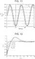
- FIG. 12 is a view for illustrating a problem in P.L. Lee, G.R. Sullivan, “Generic Model Control (GMC)", Computer and Chemical Engineering, 12(6), 573-580, 1988 .
- the present disclosure provides a plant control system, a plant control method, and a computer-readable medium for holding the rise in responsiveness at an appropriate level and enhancing the degree of freedom in designing response waveforms while preventing the occurrence of response overshoot.
- a plant control system is equipped with a plant, an actuator that controls a state of the plant based on a command value, and an arithmetic device that calculates the command value through use of state information indicating the state of the plant, and that outputs the calculated command value to the actuator.
- the command value u is obtained through the use of the equation (A1) and the equation (A2) where the coefficients K 1 and K 3 are different from each other. Therefore, the rise in responsiveness can be held at an appropriate level, and the degree of freedom in designing response waveforms can be enhanced, while preventing the overshoot of the response of y.
- the plant control system may be applicable to any plant that is expressed by the equation (A1), regardless of whether the plant is linear or nonlinear. As a result, the application range of the plant control system is widened.
- the K 3 may be a zero matrix
- the equation is made simpler than the equation (A2), and the load of the process of calculating the command value u is reduced.
- the plant may be a fuel cell system that includes a fuel cell stack, a flow rate adjusting valve, and a discharging valve that discharges gas or drains water from the fuel cell stack
- the actuator may be a current control device configured to control a state of the fuel cell system by a step-up converter
- the plant control system may be further equipped with a hydrogen pressure sensor that measures a hydrogen pressure value of the fuel cell stack and that outputs the hydrogen pressure value to the arithmetic device as the state information.
- P the hydrogen pressure value
- R is a gas constant
- T is a temperature of the fuel cell stack
- V is a hydrogen volume
- Q inj is a flow rate adjusted by the flow rate adjusting valve
- N is a number of cells in the fuel cell stack
- F is a Faraday constant
- I u is a current limit value of the fuel cell stack as the command value that is output to the current control device
- Q hev is a flow rate adjusted by the discharging valve
- Q crs is a crossover flow rate.
- P ref is a target value of P
- T 1 and T 2 are time constants of the response of P to P ref .
- each of T 1 and T 2 may be a value satisfying a first condition indicating that an amount of fall in P from P ref corresponding to the time constant is smaller than a first threshold, and a second condition indicating that an amount of change in a minimum current value in the fuel cell stack with respect to the time constant is equal to or smaller than a second threshold.
- the minimum current value may have been limited by I u .
- the plant control system may be further equipped with a sensor that acquires a state amount of the plant and that outputs the acquired state amount to the arithmetic device as the state information, and the arithmetic device may calculate the command value through use of the state information acquired from the sensor.
- a sensor that acquires a state amount of the plant and that outputs the acquired state amount to the arithmetic device as the state information
- the arithmetic device may calculate the command value through use of the state information acquired from the sensor.
- each of K 1 , the K 2 , and the K 4 may be a row vector where remaining components other than a common component are equal to 0. This can make it easy to focus on the control for the response of at least one important index among a plurality of kinds of indices.
- the command value can be efficiently calculated by narrowing down the state information to the angle.
- a computer-readable medium stores a program for causing a computer to perform a process.
- the present disclosure makes it possible to provide a plant control system, a plant control method, and a computer-readable medium for holding the rise in responsiveness at an appropriate level and enhancing the degree of freedom in designing response waveforms while preventing the occurrence of response overshoot.
- FIG. 1 is a block diagram showing the configuration of a plant control system 1000 according to the first embodiment.
- the plant control system 1000 is equipped with a plant 1, a sensor 2, an arithmetic device 3, and an actuator 4.
- the plant 1 is a system that produces a predetermined physical quantity from a predetermined raw material.
- the plant 1 encompasses, for example, a fuel cell system, an internal combustion engine that is employed as a motive power device of an automobile, a motor, an inverted pendulum, and the like, but is not limited thereto.
- the actuator 4 controls the plant 1.
- the sensor 2 measures a state amount of the plant 1, and outputs a result of this measurement to the arithmetic device 3 as state information y.
- the sensor 2 encompasses, for example, a low-pressure hydrogen pressure sensor or an airflow meter for measuring a flow rate of air and an instrument for measuring a pressure of air, and the like, but is not limited thereto.
- an estimator that estimates the physical quantity representing the state of the plant 1 may be employed instead of the sensor 2.
- the estimator outputs an estimated value of the physical quantity to the arithmetic device 3 as the state information y.
- the estimator may adopt, for example, a pressure at an inlet of a hydrogen pump as the estimated value of the physical quantity.
- the word "acquire” includes the word “measure” and "estimate” in the present specification.
- the arithmetic device 3 calculates a command value u according to a method that will be described later, through the use of the state information y indicating the state of the plant 1, and outputs the calculated command value u to the actuator 4. For example, the arithmetic device 3 accepts the inputting of a measured value measured by the sensor 2 as the state information y, and calculates the command value u through the use of the measured value. Alternatively, the arithmetic device 3 accepts the inputting of an estimated value of a physical quantity estimated by the estimator as the state information y, and calculates the command value u through the use of the estimated value of the physical quantity.
- the actuator 4 generates a control signal for controlling the production in the plant 1, based on the command value u from the arithmetic device 3, and outputs the control signal to the plant 1. It should be noted herein that either the single actuator 4 or a plurality of actuators 4 may be provided. Furthermore, for example, an FC (fuel cell) current control device or an air compressor and an air pressure adjusting valve and the like can be mentioned as the actuator 4, but the actuator 4 is not limited thereto.
- FC fuel cell
- the arithmetic device 3 calculates, as the command value u, a value of u obtained by deleting ⁇ from an equation (11) shown below and an equation (12) shown below, through the use of the state information y.
- y ⁇ f y u d t
- y is the state information
- u is the command value
- d is a disturbance
- t is a time
- ⁇ is a time differential of y.
- K 4 y ⁇ K 3 y ref ⁇ K 1 y + K 2 ⁇ 0 t y ref ⁇ y dt + K 5
- K 1 , K 2 , K 3 , K 4 , and K 5 are diagonal matrices, that K 1 , K 2 , and K 4 are not zero matrices, that K 1 and K 3 are different from each other, and that y ref is a target value of y.
- the arithmetic device 3 is only required to be able to calculate at least the command value u based on the equation (11) and the equation (12). Therefore, for example, "an equation solved as to u” may be calculated offline in advance from the equation (11) and the equation (12). In this case, “the equation solved as to u” is calculated by deleting y by assigning the equation (12) to the equation (11) through the use of an arbitrary information processing device. Then, "the equation solved as to u” is mounted onboard, namely, on the arithmetic device 3, and the command value u is calculated.
- an equation at a stage prior to obtaining the solution as to u may be calculated offline in advance from the equation (11) and the equation (12).
- an equation obtained by assigning the equation (12) to the equation (11), namely, an equation at a stage where the solution has not been obtained as to u although y has been deleted is calculated through the use of the arbitrary information processing device.
- the equation at the stage prior to obtaining the solution as to u is mounted onboard, namely, on the arithmetic device 3, and the command value u is calculated.
- Equation (13) may be used instead of the equation (12), by setting K 3 as a zero matrix in the equation (12).
- K 4 y ⁇ ⁇ K 1 y + K 2 ⁇ 0 t y ref ⁇ y dt + K 5
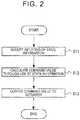
- FIG. 2 is a flowchart for illustrating the flow of a plant control method according to the first embodiment.
- the arithmetic device 3 accepts the inputting of state information (S11). Subsequently, the arithmetic device 3 calculates a command value through the use of the state information (S12). For example, the arithmetic device 3 calculates the command value according to "the equation solved as to u" or "the equation at the stage prior to obtaining the solution as to u", which are based on the equation (11) and the equation (12) or the equation (11) and the equation (13). Then, the arithmetic device 3 outputs the calculated command value to the actuator 4 (S13). After that, the actuator 4 controls the state of the plant 1 based on the command value accepted from the arithmetic device 3.
- the arithmetic device 3 may be a computer device that operates by being logically endowed with such a function through the execution of a program stored in a built-in memory or read therefrom by a built-in processor.
- n-th component in the vector in the equation (12) is expressed by an equation (14) shown below.
- k 4 n y ⁇ n k 3 n y refn ⁇ k 1 n y n + k 2 n ⁇ 0 t y refn ⁇ y n dt
- y refn 1 ⁇ ⁇ ⁇ k 3 n ⁇ ⁇ 1 ⁇ e ⁇ ⁇ t + ⁇ ⁇ k 3 n 1 ⁇ e ⁇ ⁇ t
- FIG. 13 is a view for illustrating the problem in the related art and the effect of the present disclosure.
- control method according to the present embodiment is applicable to any plant that can be expressed by the equation (11), regardless of whether the plant is linear or non-linear, and hence guarantees a wide application range. Furthermore, four simple arithmetic operations and differential and integral calculus are sufficient to transform equations in calculating a control rule. Therefore, the utilization of the present embodiment is promoted due to its simplicity.
- FIG. 3 is a block diagram showing the configuration of a fuel cell control system 2000 according to the second embodiment.
- the fuel cell control system 2000 is an example of the above-mentioned plant control system 1000, and is equipped with a fuel cell system 11, a low-pressure hydrogen pressure sensor 21, an electronic control unit (an ECU) 31, and a current control device 41.
- the fuel cell system 11 is an example of the above-mentioned plant 1
- the low-pressure hydrogen pressure sensor 21 is an example of the above-mentioned sensor 2
- the ECU 31 is an example of the above-mentioned arithmetic device 3
- the current control device 41 is an example of the above-mentioned actuator 4.
- the fuel cell system 11 is an electric power generation system based on a polymer electrolyte fuel cell that generates electric power by being supplied with hydrogen and air.
- the fuel cell system 11 is equipped with at least a stack 111, an injector 112, and a drain valve 113.
- the fuel cell system 11 further includes the configuration of a general fuel cell system such as an oxygen system and the like, but the description and depiction thereof will be omitted.
- the injector 112 is an example of the flow rate adjusting valve.
- the drain valve 113 may be an exhaust valve. That is, the drain valve 113 is an example of the valve that discharges air or drains water, and adjusts a flow rate of the discharged anode-off gas.
- the injector 112 is a flow rate adjusting valve for adjusting the flow rate of hydrogen supplied to the stack 111 from a hydrogen tank (not shown).
- the stack 111 is a fuel cell that generates electric power through an electrochemical reaction between the atmosphere containing the oxygen supplied from the oxygen system (not shown) and the hydrogen supplied via the injector 112. Besides, the stack 111 is configured as an assembly of a plurality of cells.
- the drain valve 113 is a valve for draining the water produced through the reaction in the stack 111.
- the low-pressure hydrogen pressure sensor 21 measures a pressure value of the hydrogen supplied to the stack 111 via the injector 112, and outputs the measured pressure value to the ECU 31 as a low-pressure hydrogen pressure value P.
- the ECU 31 accepts the inputting of the low-pressure hydrogen pressure value P from the low-pressure hydrogen pressure sensor 21, calculates a current limit value I u through the use of the low-pressure hydrogen pressure value P, and outputs the current limit value I u to the current control device 41.
- the current control device 41 includes at least an FDC-ECU 411 and a step-up converter 412.
- the current control device 41 controls the state of the fuel cell system 11 by the step-up converter 412.
- the FDC-ECU 411 is a control device that controls the step-up converter 412 based on the current limit value I u accepted from the ECU 31.
- the FDC-ECU 411 generates a control signal CS for holding the current at the current limit value I u , and outputs the control signal CS to the step-up converter 412.
- the step-up converter 412 enhances the voltage of the electric power that has been generated in and output from the stack 111 and whose current is equal to I to a predetermined voltage, holds the current I at the designated predetermined current limit value I u , and outputs this current limit value I u . That is, the step-up converter 412 accepts the control signal CS from the FDC-ECU 411, adjusts the current I in accordance with the control signal CS such that the current I becomes equal to the current limit value I u , and outputs the current limit value I u .
- the ECU 31 calculates the current limit value I u through the use of the following equations.
- an equation (21) shown below is used as a concrete example of the equation (11).
- dP dt RT V Q inj ⁇ N 2 F I u ⁇ Q hev ⁇ Q crs
- P is a low-pressure hydrogen pressure value
- R is a gas constant
- T is a temperature of the fuel cell
- V is a low-pressure hydrogen volume
- Q inj is a flow rate adjusted by the injector 112
- N is the number of cells in the stack 111
- F is the Faraday constant
- I u is the current limit value of the fuel cell
- Q hev is a flow rate adjusted by the drain valve 113
- Q crs is a crossover flow rate, namely, a flow rate of penetration from the hydrogen side to the oxygen side.
- P ref is a target value of P and that T 1 and T 2 are time constants of the response of P to P ref .
- the equation (24) can be regarded as "the equation solved as to the current limit value I u ", namely, the control rule.
- an equation (25) shown below which is obtained by substituting I u0 for the term defined by the expression in the last pair of curly brackets on the right side of the equation (24) such that I u (0) becomes equal to I u0 may be regarded as "the equation solved as to the current limit value I u ", namely, the control rule.
- I u is an (FC) current limit value
- P ref is a target value of P
- T 1 and T 2 are time constants of the response of the pressure P (Pa) to the target pressure value P ref (Pa).
- P 0 is a low-pressure hydrogen pressure (Pa) at the time of the start of limitation of the current of the FC
- I u0 is an FC current (A) at the time of the start of limitation of the current of the FC
- ⁇ t is a control cycle (sec).
- FIG. 4 is a view showing examples of changes with time in the injector flow rate Q inj , the hydrogen pressure value P, and the FC current value I according to the second embodiment.
- the numerical values on the scales of the axes of ordinate in upper and lower views of FIG. 4 are relative values with respect to the origin, and should not be limited to any concrete numerical values.
- the stack 111 continues to generate electric power while the supply amount of hydrogen remains insufficient. Therefore, the hydrogen pressure value P falls. Then, the low-pressure hydrogen pressure sensor 21 measures the hydrogen pressure value P that has fallen, and outputs the measured hydrogen pressure value P to the ECU 31. Then, the ECU 31 calculates the current limit value I u through the use of the hydrogen pressure value P that has fallen, and issues a command to the step-up converter 412 via the FDC-ECU 411. In consequence, the step-up converter 412 limits the current I of the electric power generated by the stack 111 to the current limit value I u . Thus, the consumption amount of hydrogen in the stack 111 is held small, and the hydrogen pressure value P recovers. At this time, the hydrogen pressure value P smoothly converges toward the target value P ref and does not overshoot.
- FIG. 5 is a view showing a relationship between the time constant and the hydrogen pressure value according to the second embodiment.
- the follow-up progresses slowly when T is large. Furthermore, the amount of limitation of the FC current is small when the follow-up progresses slowly. Therefore, the limited FC current becomes large. Then, when the limited FC current becomes large, the width by which the pressure falls below the target lower limit becomes large, and the stack is likely to deteriorate. At the same time, when the limited FC current becomes large, the operating performance level becomes high.
- the fuel cell control system 2000 is mathematically modelled, a simulation of the control of the fuel cell is carried out as to models having various time constants, by the arbitrary information processing device, and combinations of a minimum current value of the electric power generated after limiting the current, a pressure value, and a time constant are saved into a storage device as a result of the control. Then, the information processing device specifies the time constants T 1 and T 2 in those of the saved combinations in which the minimum current value and the pressure value satisfy conditions that will be described later. Then, the ECU 31 can calculate the optimal current limit value I u by applying the specified time constants T 1 and T 2 to the equation (24) or the equation (25).
- the information processing device carries out the aforementioned simulation as to various time constants, and calculates a difference between the pressure target value P ref at each of the time constants and the pressure value P as the control result thereof.
- the pressure value P is lower than the pressure target value P ref due to the above-mentioned follow-up performance, so the difference therebetween is an amount of fall in the pressure value P with respect to the pressure target value P ref at a certain time constant.
- the upper view of FIG. 6 shows a relationship between the time constant and the amount of fall in the pressure value P from the pressure target value P ref corresponding to the time constant.
- each of T 1 and T 2 is desired to satisfy a first condition indicating that the amount of fall in P from P ref corresponding to the time constant is smaller than the first threshold.
- the information processing device carries out the aforementioned simulation as to various time constants, limits the current in the step-up converter to the current limit value calculated at each of the time constants, and calculates the minimum current value of the electric power generated by the fuel cell after limitation.
- the lower view of FIG. 6 shows a relationship between the time constant and the minimum current value of the electric power generated after being limited to the current limit value corresponding to the time constant.
- the term "balance" in FIG. 6 is equivalent to a value of "the injector flow rate Q inj - the exhaust drain valve flow rate Q hev - the crossover flow rate Q crs ". As described hitherto, even when the time constant becomes large, the limited minimum current value does not continue to rise.
- the limited minimum current value is substantially constant. That is, each of T 1 and T 2 is desired to satisfy a second condition indicating that the amount of change in the minimum current value in the fuel cell after being limited to the current limit value with respect to the time constant is equal to or smaller than a second threshold (i.e., there is no change).
- the second threshold is equal to, for example, 0.
- the second condition may indicate that each of T 1 and T 2 is a time constant upon or after the convergence of the minimum current value in the fuel cell after being limited to the current limit value to a third threshold.
- each of T 1 and T 2 is a value satisfying the aforementioned first condition and the aforementioned second condition.
- the numerical values on the scales of the axes of ordinate in the upper and lower views of FIG. 6 are relative values with respect to the origin, and should not be limited to any concrete numerical values.
- FIG. 7 is a block diagram showing the configuration of a torque control system 3000 according to the third embodiment.
- the torque control system 3000 is an example of the above-mentioned plant control system 1000, and is equipped with a motor 12, a sensor 22, an ECU 32, and a torque control unit 42.
- a motor of an air compressor can be mentioned as the motor 12, but the motor 12 is not limited thereto.
- the sensor 22 measures a rotational speed ⁇ of the motor 12, and outputs the rotational speed ⁇ to the ECU 32.
- the ECU 32 accepts the inputting of the rotational speed ⁇ from the sensor 22, calculates an input torque ⁇ in an inverter 422 through the use of the rotational speed ⁇ , and outputs the input torque ⁇ to the torque control unit 42.
- the torque control unit 42 is equipped with an ECU 421 and the inverter 422.
- the ECU 421 performs torque control by the inverter 422 through the use of the input torque ⁇ accepted from the ECU 32.
- the motor 12 is an example of the above-mentioned plant 1
- the sensor 22 is an example of the above-mentioned sensor 2
- the ECU 32 is an example of the above-mentioned arithmetic device 3
- the torque control unit 42 is an example of the above-mentioned actuator 4.
- the ECU 32 calculates the input torque ⁇ such that the rotational speed ⁇ of the motor 12 follows up the input torque ⁇ , through the use of the following equations.
- J is an inertia moment
- ⁇ is an angular velocity (the rotational speed of the motor 12)
- ⁇ is an input torque resulting from the inverter 422
- ⁇ L is a load torque
- k 3 and k 1 are different values, and that ⁇ ref is a target value of ⁇ .
- an equation solved as to the input torque ⁇ can be derived as follows. That is, when the equation (32) is assigned to the equation (31) and the time differential of the angular velocity ⁇ is deleted to transform the equation, an equation (33) shown below is established. That is, the equation (33) can be regarded as the control rule.
- ⁇ Jk 3 ⁇ ref + a ⁇ Jk 1 ⁇ + Jk 2 ⁇ 0 t ⁇ ref ⁇ ⁇ dt + ⁇ L ⁇
- the motor 12 can be expressed by the equation (31). Therefore, the rise in responsiveness can be held at an appropriate level, and the degree of freedom in designing response waveforms can be enhanced, while preventing the occurrence of response overshoot, through the use of the equation (33).
- the fourth embodiment is another concrete example of the above-mentioned first embodiment.
- FIGS. 8 and 9 are a view showing the external configuration of an inverted pendulum as a control target of an inverted pendulum control system 4000 according to the fourth embodiment.
- FIG. 8 is a front view
- FIG. 9 is a lateral view.
- the inverted pendulum control system 4000 is an example of the above-mentioned plant control system 1000, and is equipped with a handle 131, a vehicle body 132, wheels 133A and 133B, and drive units 43A and 43B.
- the handle 131 is a T-shaped operating helm that is gripped by a passenger.
- the wheel 133A and the wheel 133B which constitute a pair of right and left wheels, are rotatably provided on the vehicle body 132.
- the inverted pendulum is configured as, for example, a coaxial two-wheel vehicle in which the respective wheels 133A and 133B are arranged parallel along a coaxial core line on the vehicle body 132 as a region where the passenger stands, but is not limited thereto.
- the present embodiment is applicable to an arbitrary inverted movable body. Besides, the present embodiment is also applicable to a dolly and a pendulum of a four-wheel vehicle.
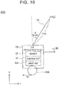
- FIG. 10 is a block diagram showing the configuration of the inverted pendulum control system 4000 according to the fourth embodiment.
- the handle 131 has a length of 21 (m) and a mass of m (kg).
- An angle ⁇ is an angle that is formed by the handle 131 with respect to a vertical direction.
- the vehicle body 132 has a mass of M (kg).
- a sensor 23, a control unit 33, and the drive units 43A and 43B are included inside the vehicle body 132.
- the sensor 23 detects the angle ⁇ of the handle 131 and a moving distance x of the vehicle body 132 in an x-direction, and outputs the detected angle ⁇ and the detected moving distance x to the control unit 33.
- the control unit 33 calculates a command value of a force u f applied to the vehicle body 132 in the x-direction based on the angle ⁇ from the sensor 23, the moving distance x from the sensor 23, the angular velocity ⁇ as a time differential of the angle ⁇ , and a speed v as a time differential of the moving distance x, and outputs the calculated command value of the force u f to the drive units 43A and 43B.
- the drive units 43A and 43B drive the wheels 133A and 133B respectively such that the force u f is applied to the vehicle body 132.
- the handle 131, (an outer frame of) the vehicle body 132, and the wheels 133A and 133B are examples of the above-mentioned plant 1.
- the sensor 23 is an example of the above-mentioned sensor 2
- the control unit 33 is an example of the above-mentioned arithmetic device 3
- the drive units 43A and 43B are examples of the above-mentioned actuator 4.
- control unit 33 calculates the force u f through the use of the following equations.
- equation (41) shown below is used as a concrete example of the equation (11).
- B is a viscous friction coefficient (kg/s) between the dolly (the wheels 133A and 133B) and a floor
- C is a viscous friction coefficient (kgm2/s) between the pendulum (the handle 131) and the dolly.
- each of K 1 , K 2 , and K 4 is set as a four-component row vector, the second component is made equal to 1, and the remaining components, namely, the first, third, and fourth components are made equal to 0.
- u f ⁇ M + m J + ml 2 ml cos ⁇ + ml cos ⁇ k 1 2 ⁇ + k 2 ⁇ ref ⁇ ⁇ ⁇ k 1 k 2 ⁇ 0 t ⁇ ref ⁇ ⁇ dt ⁇ mlsin ⁇ ⁇ k 1 ⁇ + k 2 ⁇ 0 t ⁇ ref ⁇ ⁇ dt 2 + M + m ml cos ⁇ mlg sin ⁇ ⁇ C ⁇ k 1 ⁇ + k 2 ⁇ 0 t ⁇ ref ⁇ ⁇ dt + Bv
- control rule according to the present embodiment can be expressed by four simple arithmetic operations and simple differentiation and integration as in the equation (44).
- FIG. 11 is a view showing an example of follow-up of the angle of the inverted pendulum according to the fourth embodiment.
- the angle ⁇ can follow up a target value ⁇ ref of the angle.
- the inverted pendulum can be expressed by the equation (41) as the plant. Therefore, the rise in responsiveness can be held at an appropriate level, and the degree of freedom in designing response waveforms can be enhanced, while preventing the occurrence of response overshoot, through the use of the equation (44).
- each of K 1 , K 2 , and K 4 is a row vector where the remaining components (e.g., the first, third, and fourth components) other than at least one common component (e.g., the second component) are equal to 0.
- the force u f can be efficiently calculated by focusing on the angular velocity ⁇ among the measured values of the sensor 23.
- the above-mentioned present disclosure is applicable to a control apparatus that operates actuators based on sensor values of automobiles, devices for manufacturing parts, various facilities, devices for manufacturing materials, home electrical appliances, and the like.
- the present disclosure is not limited to the aforementioned embodiments, but can be appropriately changed within such a range as not to depart from the gist thereof.
- the invention has been described as a hardware configuration in each of the above-mentioned embodiments, the present disclosure should not be limited thereto.
- an arbitrary process can also be realized by causing a central processing unit (a CPU) to execute a computer program.
- the program can be stored through the use of various types of non-transitory computer-readable media and supplied to a computer.
- the non-transitory computer-readable media encompass various types of tangible storage media. Examples of the non-transitory computer-readable media include a magnetic recording medium (e.g., a flexible disk, a magnetic tape, or a hard disk drive), a magnetooptical recording medium (e.g., a magnetooptical disk), a CD-ROM (a read only memory), a CD-R, a CD-R/W, a digital versatile disc (a DVD), a semiconductor memory (e.g., a mask ROM, a programmable ROM (a PROM), an erasable PROM (an EPROM), a flash ROM, or a random access memory (a RAM)).
- a magnetic recording medium e.g., a flexible disk, a magnetic tape, or a hard disk drive
- a magnetooptical recording medium e.g., a magnetooptical disk
- the program may be supplied to the computer by various types of transitory computer-readable media.
- Examples of the transitory computer-readable media include an electric signal, an optical signal, and an electromagnetic wave.
- Each of the transitory computer-readable media can supply the program to the computer via a wired communication path such as an electric wire, an optical fiber or the like, or a wireless communication path.
Landscapes
- Engineering & Computer Science (AREA)
- Physics & Mathematics (AREA)
- General Physics & Mathematics (AREA)
- Automation & Control Theory (AREA)
- General Chemical & Material Sciences (AREA)
- Sustainable Energy (AREA)
- Electrochemistry (AREA)
- Chemical Kinetics & Catalysis (AREA)
- Chemical & Material Sciences (AREA)
- Life Sciences & Earth Sciences (AREA)
- Manufacturing & Machinery (AREA)
- Sustainable Development (AREA)
- Mathematical Physics (AREA)
- Pure & Applied Mathematics (AREA)
- Computational Mathematics (AREA)
- Mathematical Analysis (AREA)
- Mathematical Optimization (AREA)
- Theoretical Computer Science (AREA)
- Data Mining & Analysis (AREA)
- Software Systems (AREA)
- Operations Research (AREA)
- General Engineering & Computer Science (AREA)
- Databases & Information Systems (AREA)
- Algebra (AREA)
- Computing Systems (AREA)
- Health & Medical Sciences (AREA)
- Artificial Intelligence (AREA)
- Evolutionary Computation (AREA)
- Fuzzy Systems (AREA)
- Medical Informatics (AREA)
- Feedback Control In General (AREA)
- Fuel Cell (AREA)
- Testing And Monitoring For Control Systems (AREA)
- Electric Propulsion And Braking For Vehicles (AREA)
Abstract
Description
- The invention relates to a plant control system, a plant control method, and a computer-readable medium.
- In P.L. Lee, G.R. Sullivan, "Generic Model Control (GMC)", Computer and Chemical Engineering, 12(6), 573-580, 1988, there is disclosed an art concerning general model control applicable to the control of a plant or the like. In this art, an equation (92) shown below is defined when a relationship between an input vector u (a command value to an actuator) of the plant or the like and an output vector y of the plant or the like is expressed by an equation (91) shown below.

- It should be noted herein that y is an output vector, that u is an input vector, that d is a disturbance vector, that t is a time, and ẏ is a time differential of y.

- It should be noted herein that K1 and K2 are diagonal matrices and are design factors determined at the time at which a control is designed. Besides, yref is a target value of y.
- Then, an equation solved for the input vector u after deleting ẏ by substituting the equation (92) to the equation (91) is regarded as a control rule. After that, the plant or the like is controlled through the use of the input vector u calculated according to the control rule.
- However, when the control is performed through the use of the aforementioned control rule in P.L. Lee, G.R. Sullivan, "Generic Model Control (GMC)", Computer and Chemical Engineering, 12(6), 573-580, 1988, the response of y to yref may overshoot because the coefficients K1 and K2 of yref and y assume a common value. Furthermore, when the control for preventing this overshoot is performed, the responsiveness of the control may become too high.
FIG. 12 is a view for illustrating a problem in P.L. Lee, G.R. Sullivan, "Generic Model Control (GMC)", Computer and Chemical Engineering, 12(6), 573-580, 1988. It is demonstrated herein that overshoot is caused when ε = 0.5 in the case where a target value x/x* = 1.0, and that the responsiveness of the control is too high when ε = 10 in the case where the target value x/x* = 1.0. It is therefore safe to conclude that the degree of freedom in designing a response waveform is low in P.L. Lee, G.R. Sullivan, "Generic Model Control (GMC)", Computer and Chemical Engineering, 12(6), 573-580, 1988. - It should be noted herein that, as described above, the response of the aforementioned y overshoots because the coefficients K1 and K2 of yref and y assume a common value. This will be concretely explained. First of all, the n-th component in the vector in the aforementioned equation (92) is expressed by an equation (93) shown below.

- Then, when it is assumed that k3n is a coefficient of yrefn as another variable, and further, that k1n = α+β and k2n = αβ (α and β are real numbers and α ≥ β), an equation (94) shown below is established.

- It should be noted herein that when the equation (94) is subjected to Laplace transformation and arranged, an equation (95) shown below is established.

- It should be noted herein that s is a complex number. Furthermore, a simple secondary delay is caused when k3n = 0.
- Besides, a solution of a differential equation is expressed by an equation (96) shown below when a step input is added to yrefn in the equation (95).

- It should be noted herein that a solid line portion (k3n = k1n) in
FIG. 13 shows changes with time in y in the case where α = 4 and β = 2 in the equation (96). As described hitherto, overshoot is caused when the equation (92) is used. - The present disclosure provides a plant control system, a plant control method, and a computer-readable medium for holding the rise in responsiveness at an appropriate level and enhancing the degree of freedom in designing response waveforms while preventing the occurrence of response overshoot.
- A plant control system according to a first aspect of the present disclosure is equipped with a plant, an actuator that controls a state of the plant based on a command value, and an arithmetic device that calculates the command value through use of state information indicating the state of the plant, and that outputs the calculated command value to the actuator. The arithmetic device adopts, as the command value, a value of u obtained by deleting y from the following equations (A1) and (A2),


- As described hitherto, in the present aspect, the command value u is obtained through the use of the equation (A1) and the equation (A2) where the coefficients K1 and K3 are different from each other. Therefore, the rise in responsiveness can be held at an appropriate level, and the degree of freedom in designing response waveforms can be enhanced, while preventing the overshoot of the response of y.
- Besides, the plant control system may be configured such that when k1ii, k2ii, and k3ii are non-zero (i, i) components of K1, K2, and K3 respectively, k3ii ≤ αi when k1iii = αi+βi, k2ii = αiβi, αi and βi are positive real numbers, and αi ≥ βi. Thus, the plant control system may be applicable to any plant that is expressed by the equation (A1), regardless of whether the plant is linear or nonlinear. As a result, the application range of the plant control system is widened.
- Furthermore, the K3 may be a zero matrix, and the equation (A2) may be the following equation (A3),

- Thus, the equation is made simpler than the equation (A2), and the load of the process of calculating the command value u is reduced.
- Furthermore, the plant may be a fuel cell system that includes a fuel cell stack, a flow rate adjusting valve, and a discharging valve that discharges gas or drains water from the fuel cell stack, the actuator may be a current control device configured to control a state of the fuel cell system by a step-up converter, and the plant control system may be further equipped with a hydrogen pressure sensor that measures a hydrogen pressure value of the fuel cell stack and that outputs the hydrogen pressure value to the arithmetic device as the state information. In this case, the equation (A1) may be the following equation (A4),


- Furthermore, each of T1 and T2 may be a value satisfying a first condition indicating that an amount of fall in P from Pref corresponding to the time constant is smaller than a first threshold, and a second condition indicating that an amount of change in a minimum current value in the fuel cell stack with respect to the time constant is equal to or smaller than a second threshold. The minimum current value may have been limited by Iu. Thus, the balance between the deterioration of the stack and the dynamic performance can be optimally controlled.
- Besides, the plant control system may be further equipped with a sensor that acquires a state amount of the plant and that outputs the acquired state amount to the arithmetic device as the state information, and the arithmetic device may calculate the command value through use of the state information acquired from the sensor. Thus, since an actually acquired value of the state amount of the plant is used, a more appropriate command value can be calculated, and the state of the plant can be more accurately controlled.
- Besides, each of K1, the K2, and the K4 may be a row vector where remaining components other than a common component are equal to 0. This can make it easy to focus on the control for the response of at least one important index among a plurality of kinds of indices. For example, in the case where the plant is an inverted pendulum, the command value can be efficiently calculated by narrowing down the state information to the angle.
- A plant control method according to a second aspect of the present disclosure includes accepting inputting of state information indicating a state of a plant in an arithmetic device (3), calculating, as a command value, a value of u obtained by deleting y from the following equations (A6) and (A7) through use of the state information, in the arithmetic device (3),


- Besides, a computer-readable medium according to a third aspect of the present disclosure stores a program for causing a computer to perform a process. The process includes processing of accepting inputting of state information indicating a state of a plant, processing of calculating, as a command value, a value of u obtained by deleting ẏ from the following equations (A8) and (A9),


- The present disclosure makes it possible to provide a plant control system, a plant control method, and a computer-readable medium for holding the rise in responsiveness at an appropriate level and enhancing the degree of freedom in designing response waveforms while preventing the occurrence of response overshoot.
- Features, advantages, and technical and industrial significance of exemplary embodiments of the invention will be described below with reference to the accompanying drawings, in which like numerals denote like elements, and wherein:
-
FIG. 1 is a block diagram showing the configuration of a plant control system according to the first embodiment; -
FIG. 2 is a flowchart for illustrating the flow of a plant control method according to the first embodiment; -
FIG. 3 is a block diagram showing the configuration of a fuel cell control system according to the second embodiment; -
FIG. 4 is a view showing examples of changes with time in an injector flow rate, a hydrogen pressure value, and an FC current value according to the second embodiment; -
FIG. 5 is a view showing a relationship between a time constant and the hydrogen pressure value according to the second embodiment; -
FIG. 6 is a view showing how the time constant is related to a pressure change amount and a minimum current value according to the second embodiment; -
FIG. 7 is a block diagram showing the configuration of a torque control system according to the third embodiment; -
FIG. 8 is a front view showing the external configuration of an inverted pendulum according to the fourth embodiment; -
FIG. 9 is a lateral view showing the external configuration of the inverted pendulum according to the fourth embodiment; -
FIG. 10 is a block diagram showing the configuration of an inverted pendulum control system according to the fourth embodiment; -
FIG. 11 is a view showing an example of follow-up of the angle of the inverted pendulum according to the fourth embodiment; -
FIG. 12 is a view for illustrating a problem in the related art; and -
FIG. 13 is a view for illustrating the problem in the related art and an effect of the present disclosure. - The concrete embodiments to which the present disclosure including the above-mentioned respective aspects is applied will be described hereinafter in detail with reference to the drawings. Like elements are denoted by like reference symbols in the respective drawings, and redundant description thereof will be omitted as necessary for the sake of clear explanation.
- 〈First Embodiment〉
FIG. 1 is a block diagram showing the configuration of aplant control system 1000 according to the first embodiment. Theplant control system 1000 is equipped with aplant 1, asensor 2, anarithmetic device 3, and anactuator 4. Theplant 1 is a system that produces a predetermined physical quantity from a predetermined raw material. Theplant 1 encompasses, for example, a fuel cell system, an internal combustion engine that is employed as a motive power device of an automobile, a motor, an inverted pendulum, and the like, but is not limited thereto. Theactuator 4 controls theplant 1. - The
sensor 2 measures a state amount of theplant 1, and outputs a result of this measurement to thearithmetic device 3 as state information y. It should be noted herein that either thesingle sensor 2 or a plurality ofsensors 2 may be provided. Furthermore, thesensor 2 encompasses, for example, a low-pressure hydrogen pressure sensor or an airflow meter for measuring a flow rate of air and an instrument for measuring a pressure of air, and the like, but is not limited thereto. Incidentally, an estimator that estimates the physical quantity representing the state of theplant 1 may be employed instead of thesensor 2. Furthermore, the estimator outputs an estimated value of the physical quantity to thearithmetic device 3 as the state information y. It should be noted herein that the estimator may adopt, for example, a pressure at an inlet of a hydrogen pump as the estimated value of the physical quantity. The word "acquire" includes the word "measure" and "estimate" in the present specification. - The
arithmetic device 3 calculates a command value u according to a method that will be described later, through the use of the state information y indicating the state of theplant 1, and outputs the calculated command value u to theactuator 4. For example, thearithmetic device 3 accepts the inputting of a measured value measured by thesensor 2 as the state information y, and calculates the command value u through the use of the measured value. Alternatively, thearithmetic device 3 accepts the inputting of an estimated value of a physical quantity estimated by the estimator as the state information y, and calculates the command value u through the use of the estimated value of the physical quantity. - The
actuator 4 generates a control signal for controlling the production in theplant 1, based on the command value u from thearithmetic device 3, and outputs the control signal to theplant 1. It should be noted herein that either thesingle actuator 4 or a plurality ofactuators 4 may be provided. Furthermore, for example, an FC (fuel cell) current control device or an air compressor and an air pressure adjusting valve and the like can be mentioned as theactuator 4, but theactuator 4 is not limited thereto. - It should be noted herein that the
arithmetic device 3 calculates, as the command value u, a value of u obtained by deleting ẏ from an equation (11) shown below and an equation (12) shown below, through the use of the state information y.
- It should be noted herein that y is the state information, that u is the command value, that d is a disturbance, that t is a time, and that ẏ is a time differential of y.

- It should be noted herein that K1, K2, K3, K4, and K5 are diagonal matrices, that K1, K2, and K4 are not zero matrices, that K1 and K3 are different from each other, and that yref is a target value of y.
- Incidentally, the
arithmetic device 3 is only required to be able to calculate at least the command value u based on the equation (11) and the equation (12). Therefore, for example, "an equation solved as to u" may be calculated offline in advance from the equation (11) and the equation (12). In this case, "the equation solved as to u" is calculated by deleting y by assigning the equation (12) to the equation (11) through the use of an arbitrary information processing device. Then, "the equation solved as to u" is mounted onboard, namely, on thearithmetic device 3, and the command value u is calculated. - Alternatively, "an equation at a stage prior to obtaining the solution as to u" may be calculated offline in advance from the equation (11) and the equation (12). In this case, an equation obtained by assigning the equation (12) to the equation (11), namely, an equation at a stage where the solution has not been obtained as to u although y has been deleted is calculated through the use of the arbitrary information processing device. Then, "the equation at the stage prior to obtaining the solution as to u" is mounted onboard, namely, on the
arithmetic device 3, and the command value u is calculated. - Besides, an equation (13) shown below may be used instead of the equation (12), by setting K3 as a zero matrix in the equation (12).

-
FIG. 2 is a flowchart for illustrating the flow of a plant control method according to the first embodiment. First of all, thearithmetic device 3 accepts the inputting of state information (S11). Subsequently, thearithmetic device 3 calculates a command value through the use of the state information (S12). For example, thearithmetic device 3 calculates the command value according to "the equation solved as to u" or "the equation at the stage prior to obtaining the solution as to u", which are based on the equation (11) and the equation (12) or the equation (11) and the equation (13). Then, thearithmetic device 3 outputs the calculated command value to the actuator 4 (S13). After that, theactuator 4 controls the state of theplant 1 based on the command value accepted from thearithmetic device 3. - Incidentally, the
arithmetic device 3 may be a computer device that operates by being logically endowed with such a function through the execution of a program stored in a built-in memory or read therefrom by a built-in processor. - It should be noted herein that the n-th component in the vector in the equation (12) is expressed by an equation (14) shown below.

- Then, when the coefficient of yrefn is set as another variable, namely, k3n, k1n = α+β and k2n = αβ (α and β are positive real numbers and α ≥ β) are further established, subjected to Laplace transformation, and arranged, and a step input is further added to yrefn to solve a differential equation, an equation (15) shown below is established.

- It should be noted herein that the occurrence of overshoot can be prevented by selecting k3n such that k3n ≤ α.
- Incidentally, the foregoing can also be rephrased in the following manner. That is, in the case where k1ii, k2ii, and k3ii are non-zero (i, i) components of K1, K2, and K3 respectively in the equation (12), the occurrence of overshoot can be prevented by selecting k3ii such that k3ii ≤ αi when k1ii = αi+βi, k2ii = αiβi, αi and βi are positive real numbers, and αi ≥ βi.
- It should be noted herein that
FIG. 13 is a view for illustrating the problem in the related art and the effect of the present disclosure.FIG. 13 shows changes with time in y by a broken line (k3n = α) and a dotted line (k3n = 0) when α = 4 and β = 2 in the equation (15) (and k3n is different from k1n). It is thus demonstrated that there is no overshoot when k3n ≤ α. In consequence, the present embodiment achieves an effect of ensuring a high degree of freedom in designing response waveforms. Incidentally, there are other control methods enabling the prevention itself of the occurrence of overshoot, but their application range is narrow. On the other hand, the control method according to the present embodiment is applicable to any plant that can be expressed by the equation (11), regardless of whether the plant is linear or non-linear, and hence guarantees a wide application range. Furthermore, four simple arithmetic operations and differential and integral calculus are sufficient to transform equations in calculating a control rule. Therefore, the utilization of the present embodiment is promoted due to its simplicity. - 〈Second Embodiment〉 The second embodiment is a concrete example of the above-mentioned first embodiment.
FIG. 3 is a block diagram showing the configuration of a fuelcell control system 2000 according to the second embodiment. The fuelcell control system 2000 is an example of the above-mentionedplant control system 1000, and is equipped with afuel cell system 11, a low-pressurehydrogen pressure sensor 21, an electronic control unit (an ECU) 31, and acurrent control device 41. Incidentally, thefuel cell system 11 is an example of the above-mentionedplant 1, the low-pressurehydrogen pressure sensor 21 is an example of the above-mentionedsensor 2, theECU 31 is an example of the above-mentionedarithmetic device 3, and thecurrent control device 41 is an example of the above-mentionedactuator 4. - The
fuel cell system 11 is an electric power generation system based on a polymer electrolyte fuel cell that generates electric power by being supplied with hydrogen and air. Thefuel cell system 11 is equipped with at least astack 111, aninjector 112, and adrain valve 113. Incidentally, thefuel cell system 11 further includes the configuration of a general fuel cell system such as an oxygen system and the like, but the description and depiction thereof will be omitted. Besides, theinjector 112 is an example of the flow rate adjusting valve. Furthermore, thedrain valve 113 may be an exhaust valve. That is, thedrain valve 113 is an example of the valve that discharges air or drains water, and adjusts a flow rate of the discharged anode-off gas. - The
injector 112 is a flow rate adjusting valve for adjusting the flow rate of hydrogen supplied to thestack 111 from a hydrogen tank (not shown). Thestack 111 is a fuel cell that generates electric power through an electrochemical reaction between the atmosphere containing the oxygen supplied from the oxygen system (not shown) and the hydrogen supplied via theinjector 112. Besides, thestack 111 is configured as an assembly of a plurality of cells. Thedrain valve 113 is a valve for draining the water produced through the reaction in thestack 111. - The low-pressure
hydrogen pressure sensor 21 measures a pressure value of the hydrogen supplied to thestack 111 via theinjector 112, and outputs the measured pressure value to theECU 31 as a low-pressure hydrogen pressure value P. TheECU 31 accepts the inputting of the low-pressure hydrogen pressure value P from the low-pressurehydrogen pressure sensor 21, calculates a current limit value Iu through the use of the low-pressure hydrogen pressure value P, and outputs the current limit value Iu to thecurrent control device 41. - The
current control device 41 includes at least an FDC-ECU 411 and a step-upconverter 412. Thecurrent control device 41 controls the state of thefuel cell system 11 by the step-upconverter 412. The FDC-ECU 411 is a control device that controls the step-upconverter 412 based on the current limit value Iu accepted from theECU 31. In concrete terms, the FDC-ECU 411 generates a control signal CS for holding the current at the current limit value Iu, and outputs the control signal CS to the step-upconverter 412. The step-upconverter 412 enhances the voltage of the electric power that has been generated in and output from thestack 111 and whose current is equal to I to a predetermined voltage, holds the current I at the designated predetermined current limit value Iu, and outputs this current limit value Iu. That is, the step-upconverter 412 accepts the control signal CS from the FDC-ECU 411, adjusts the current I in accordance with the control signal CS such that the current I becomes equal to the current limit value Iu, and outputs the current limit value Iu. - It should be noted herein that the
ECU 31 according to the present embodiment calculates the current limit value Iu through the use of the following equations. First of all, an equation (21) shown below is used as a concrete example of the equation (11).
- It should be noted herein that P is a low-pressure hydrogen pressure value, that R is a gas constant, that T is a temperature of the fuel cell, that V is a low-pressure hydrogen volume, that Qinj is a flow rate adjusted by the
injector 112, that N is the number of cells in thestack 111, that F is the Faraday constant, that Iu is the current limit value of the fuel cell, that Qhev is a flow rate adjusted by thedrain valve 113, that Qcrs is a crossover flow rate, namely, a flow rate of penetration from the hydrogen side to the oxygen side. - Besides, an equation (22) shown below is used as a concrete example of the equation (13).

- It should be noted herein that Pref is a target value of P and that T1 and T2 are time constants of the response of P to Pref.
- Then, "an equation solved as to the current limit value Iu" can be derived in the following manner. First of all, when the equation (21) and the equation (22) are transformed by deleting the time differential of the pressure P therefrom, an equation (23) shown below is established.

- Subsequently, when the integral term of the equation (23) is discretized, an equation (24) shown below is established. In consequence, the equation (24) can be regarded as "the equation solved as to the current limit value Iu", namely, the control rule.

- Alternatively, an equation (25) shown below, which is obtained by substituting Iu0 for the term defined by the expression in the last pair of curly brackets on the right side of the equation (24) such that Iu(0) becomes equal to Iu0 may be regarded as "the equation solved as to the current limit value Iu", namely, the control rule.

- It should be noted herein that Iu is an (FC) current limit value, that Pref is a target value of P, and that T1 and T2 are time constants of the response of the pressure P (Pa) to the target pressure value Pref (Pa). Besides, P0 is a low-pressure hydrogen pressure (Pa) at the time of the start of limitation of the current of the FC, Iu0 is an FC current (A) at the time of the start of limitation of the current of the FC, and Δt is a control cycle (sec).
-
FIG. 4 is a view showing examples of changes with time in the injector flow rate Qinj, the hydrogen pressure value P, and the FC current value I according to the second embodiment. Incidentally, the numerical values on the scales of the axes of ordinate in upper and lower views ofFIG. 4 are relative values with respect to the origin, and should not be limited to any concrete numerical values. First of all, from atiming 0 to atiming 1, the current I of the electric power generated by the fuel cell and the injector flow rate Qinj are balanced with each other. That is, the consumption and the supply are balanced with each other. In consequence, the hydrogen pressure value P is also constant. Subsequently, it is assumed that the injector flow rate Qinj decreases at the timing t = 1 for some reason. In this case, thestack 111 continues to generate electric power while the supply amount of hydrogen remains insufficient. Therefore, the hydrogen pressure value P falls. Then, the low-pressurehydrogen pressure sensor 21 measures the hydrogen pressure value P that has fallen, and outputs the measured hydrogen pressure value P to theECU 31. Then, theECU 31 calculates the current limit value Iu through the use of the hydrogen pressure value P that has fallen, and issues a command to the step-upconverter 412 via the FDC-ECU 411. In consequence, the step-upconverter 412 limits the current I of the electric power generated by thestack 111 to the current limit value Iu. Thus, the consumption amount of hydrogen in thestack 111 is held small, and the hydrogen pressure value P recovers. At this time, the hydrogen pressure value P smoothly converges toward the target value Pref and does not overshoot. - Subsequently, the conditions of optimal values of the time constants T1 and T2 will be described. First of all, when the equation (22) is subjected to Laplace transformation, an equation (26) shown below is established.

- It should be noted herein that s is a complex number.
FIG. 5 is a view showing a relationship between the time constant and the hydrogen pressure value according to the second embodiment. - Subsequently, an optimal value of T as T = T1 = T2 will be studied. First of all, T is a follow-up time constant, so the follow-up progresses fast when T is small. Furthermore, the amount of limitation of the FC current is large when the follow-up progresses fast. Therefore, the limited FC current becomes small. Then, when the limited FC current becomes small, the width by which the pressure falls below a target lower limit becomes small, and the stack is unlikely to deteriorate due to the deficiency of hydrogen. At the same time, when the limited FC current becomes small, the operating performance level becomes low.
- On the other hand, the follow-up progresses slowly when T is large. Furthermore, the amount of limitation of the FC current is small when the follow-up progresses slowly. Therefore, the limited FC current becomes large. Then, when the limited FC current becomes large, the width by which the pressure falls below the target lower limit becomes large, and the stack is likely to deteriorate. At the same time, when the limited FC current becomes large, the operating performance level becomes high.
- A method of specifying the optimal time constant T through the following simulation in view of the aforementioned tendency will be described. For example, the fuel
cell control system 2000 according to the present embodiment is mathematically modelled, a simulation of the control of the fuel cell is carried out as to models having various time constants, by the arbitrary information processing device, and combinations of a minimum current value of the electric power generated after limiting the current, a pressure value, and a time constant are saved into a storage device as a result of the control. Then, the information processing device specifies the time constants T1 and T2 in those of the saved combinations in which the minimum current value and the pressure value satisfy conditions that will be described later. Then, theECU 31 can calculate the optimal current limit value Iu by applying the specified time constants T1 and T2 to the equation (24) or the equation (25). - In more concrete terms, the information processing device carries out the aforementioned simulation as to various time constants, and calculates a difference between the pressure target value Pref at each of the time constants and the pressure value P as the control result thereof. The pressure value P is lower than the pressure target value Pref due to the above-mentioned follow-up performance, so the difference therebetween is an amount of fall in the pressure value P with respect to the pressure target value Pref at a certain time constant. The upper view of
FIG. 6 shows a relationship between the time constant and the amount of fall in the pressure value P from the pressure target value Pref corresponding to the time constant. As described hitherto, as long as the time constant is equal to or smaller than a certain value (a first threshold), the follow-up performance can be maintained by holding the amount of fall within a permissible range. Therefore, each of T1 and T2 is desired to satisfy a first condition indicating that the amount of fall in P from Pref corresponding to the time constant is smaller than the first threshold. - Besides, the information processing device carries out the aforementioned simulation as to various time constants, limits the current in the step-up converter to the current limit value calculated at each of the time constants, and calculates the minimum current value of the electric power generated by the fuel cell after limitation. The lower view of
FIG. 6 shows a relationship between the time constant and the minimum current value of the electric power generated after being limited to the current limit value corresponding to the time constant. Incidentally, the term "balance" inFIG. 6 is equivalent to a value of "the injector flow rate Qinj - the exhaust drain valve flow rate Qhev - the crossover flow rate Qcrs". As described hitherto, even when the time constant becomes large, the limited minimum current value does not continue to rise. Then, after the time constant has become equal to or larger than a predetermined value (0.4 in the lower view ofFIG. 6 ), the limited minimum current value is substantially constant. That is, each of T1 and T2 is desired to satisfy a second condition indicating that the amount of change in the minimum current value in the fuel cell after being limited to the current limit value with respect to the time constant is equal to or smaller than a second threshold (i.e., there is no change). The second threshold is equal to, for example, 0. Besides, the second condition may indicate that each of T1 and T2 is a time constant upon or after the convergence of the minimum current value in the fuel cell after being limited to the current limit value to a third threshold. - In consequence, optimal control can be performed when each of T1 and T2 is a value satisfying the aforementioned first condition and the aforementioned second condition. Incidentally, the numerical values on the scales of the axes of ordinate in the upper and lower views of
FIG. 6 are relative values with respect to the origin, and should not be limited to any concrete numerical values. - 〈Third Embodiment〉 The third embodiment is another concrete example of the above-mentioned first embodiment.
FIG. 7 is a block diagram showing the configuration of atorque control system 3000 according to the third embodiment. Thetorque control system 3000 is an example of the above-mentionedplant control system 1000, and is equipped with amotor 12, asensor 22, anECU 32, and atorque control unit 42. For example, a motor of an air compressor can be mentioned as themotor 12, but themotor 12 is not limited thereto. Thesensor 22 measures a rotational speed ω of themotor 12, and outputs the rotational speed ω to theECU 32. TheECU 32 accepts the inputting of the rotational speed ω from thesensor 22, calculates an input torque τ in aninverter 422 through the use of the rotational speed ω, and outputs the input torque τ to thetorque control unit 42. Thetorque control unit 42 is equipped with anECU 421 and theinverter 422. TheECU 421 performs torque control by theinverter 422 through the use of the input torque τ accepted from theECU 32. Incidentally, themotor 12 is an example of the above-mentionedplant 1, thesensor 22 is an example of the above-mentionedsensor 2, theECU 32 is an example of the above-mentionedarithmetic device 3, and thetorque control unit 42 is an example of the above-mentionedactuator 4. - It should be noted herein that the
ECU 32 according to the present embodiment calculates the input torque τ such that the rotational speed ω of themotor 12 follows up the input torque τ, through the use of the following equations. First of all, an equation (31) shown below is used as a concrete example of the equation (11).
- It should be noted herein that J is an inertia moment, that ω is an angular velocity (the rotational speed of the motor 12), that τ is an input torque resulting from the
inverter 422, and that τL is a load torque. - Besides, an equation (32) shown below is used as a concrete example of the equation (12).

- It should be noted herein that k3 and k1 are different values, and that ωref is a target value of ω.
- Then, "an equation solved as to the input torque τ" can be derived as follows. That is, when the equation (32) is assigned to the equation (31) and the time differential of the angular velocity ω is deleted to transform the equation, an equation (33) shown below is established. That is, the equation (33) can be regarded as the control rule.

- As described hitherto, in the present embodiment as well, the
motor 12 can be expressed by the equation (31). Therefore, the rise in responsiveness can be held at an appropriate level, and the degree of freedom in designing response waveforms can be enhanced, while preventing the occurrence of response overshoot, through the use of the equation (33). - 〈Fourth Embodiment〉 The fourth embodiment is another concrete example of the above-mentioned first embodiment. Each of
FIGS. 8 and9 is a view showing the external configuration of an inverted pendulum as a control target of an invertedpendulum control system 4000 according to the fourth embodiment.FIG. 8 is a front view, andFIG. 9 is a lateral view. In each ofFIGS. 8 and9 , the invertedpendulum control system 4000 is an example of the above-mentionedplant control system 1000, and is equipped with ahandle 131, avehicle body 132,wheels units handle 131 is a T-shaped operating helm that is gripped by a passenger. Thewheel 133A and thewheel 133B, which constitute a pair of right and left wheels, are rotatably provided on thevehicle body 132. The inverted pendulum is configured as, for example, a coaxial two-wheel vehicle in which therespective wheels vehicle body 132 as a region where the passenger stands, but is not limited thereto. The present embodiment is applicable to an arbitrary inverted movable body. Besides, the present embodiment is also applicable to a dolly and a pendulum of a four-wheel vehicle. -
FIG. 10 is a block diagram showing the configuration of the invertedpendulum control system 4000 according to the fourth embodiment. Thehandle 131 has a length of 21 (m) and a mass of m (kg). An angle θ is an angle that is formed by thehandle 131 with respect to a vertical direction. Thevehicle body 132 has a mass of M (kg). Asensor 23, acontrol unit 33, and thedrive units vehicle body 132. Thesensor 23 detects the angle θ of thehandle 131 and a moving distance x of thevehicle body 132 in an x-direction, and outputs the detected angle θ and the detected moving distance x to thecontrol unit 33. Thecontrol unit 33 calculates a command value of a force uf applied to thevehicle body 132 in the x-direction based on the angle θ from thesensor 23, the moving distance x from thesensor 23, the angular velocity ω as a time differential of the angle θ, and a speed v as a time differential of the moving distance x, and outputs the calculated command value of the force uf to thedrive units drive units wheels vehicle body 132. Incidentally, thehandle 131, (an outer frame of) thevehicle body 132, and thewheels plant 1. Thesensor 23 is an example of the above-mentionedsensor 2, thecontrol unit 33 is an example of the above-mentionedarithmetic device 3, and thedrive units actuator 4. - It should be noted herein that the
control unit 33 according to the present embodiment calculates the force uf through the use of the following equations. First of all, an equation (41) shown below is used as a concrete example of the equation (11).

- It should be noted herein that B is a viscous friction coefficient (kg/s) between the dolly (the
wheels - Besides, when it is assumed in the equation (13) that K1 = K2 = K4 = [0, 1, 0, 0], an equation (42) shown below is established.

- That is, each of K1, K2, and K4 is set as a four-component row vector, the second component is made equal to 1, and the remaining components, namely, the first, third, and fourth components are made equal to 0. Thus, an equation where only the angular velocity ω remains among time differentials of the input vectors can be derived.
- Then, when both the sides of the equation (42) are differentiated,
θ̇ appears on the right side. When the equation (42) is assigned to this value and arranged, an equation (43) is obtained.
- After that, when the equation (43) is assigned to the equation (41) and solved as to the force uf, an equation (44) shown below is established. In consequence, the equation (44) can be regarded as "the equation solved as to the force uf", namely, the control rule.

- That is, the control rule according to the present embodiment can be expressed by four simple arithmetic operations and simple differentiation and integration as in the equation (44).
-
FIG. 11 is a view showing an example of follow-up of the angle of the inverted pendulum according to the fourth embodiment. Thus, in the present embodiment as well, it is demonstrated that the angle θ can follow up a target value θref of the angle. In the present embodiment, the inverted pendulum can be expressed by the equation (41) as the plant. Therefore, the rise in responsiveness can be held at an appropriate level, and the degree of freedom in designing response waveforms can be enhanced, while preventing the occurrence of response overshoot, through the use of the equation (44). - Furthermore, in the present embodiment, each of K1, K2, and K4 is a row vector where the remaining components (e.g., the first, third, and fourth components) other than at least one common component (e.g., the second component) are equal to 0. This can make it easy to focus on the control for the response of at least one important index among a plurality of kinds of indices. In this case, the force uf can be efficiently calculated by focusing on the angular velocity ω among the measured values of the
sensor 23. - 〈Other Embodiments〉 The above-mentioned present disclosure is applicable to a control apparatus that operates actuators based on sensor values of automobiles, devices for manufacturing parts, various facilities, devices for manufacturing materials, home electrical appliances, and the like.
- Incidentally, the present disclosure is not limited to the aforementioned embodiments, but can be appropriately changed within such a range as not to depart from the gist thereof. For example, although the invention has been described as a hardware configuration in each of the above-mentioned embodiments, the present disclosure should not be limited thereto. In the present disclosure, an arbitrary process can also be realized by causing a central processing unit (a CPU) to execute a computer program.
- In each of the above-mentioned examples, the program can be stored through the use of various types of non-transitory computer-readable media and supplied to a computer. The non-transitory computer-readable media encompass various types of tangible storage media. Examples of the non-transitory computer-readable media include a magnetic recording medium (e.g., a flexible disk, a magnetic tape, or a hard disk drive), a magnetooptical recording medium (e.g., a magnetooptical disk), a CD-ROM (a read only memory), a CD-R, a CD-R/W, a digital versatile disc (a DVD), a semiconductor memory (e.g., a mask ROM, a programmable ROM (a PROM), an erasable PROM (an EPROM), a flash ROM, or a random access memory (a RAM)). Besides, the program may be supplied to the computer by various types of transitory computer-readable media. Examples of the transitory computer-readable media include an electric signal, an optical signal, and an electromagnetic wave. Each of the transitory computer-readable media can supply the program to the computer via a wired communication path such as an electric wire, an optical fiber or the like, or a wireless communication path.
Claims (9)
- A plant control system comprising:a plant (1);an actuator (4) that controls a state of the plant (1) based on a command value; andan arithmetic device (3) that calculates the command value through use of state information indicating the state of the plant (1), and that outputs the calculated command value to the actuator (4), whereinthe arithmetic device (3) adopts, as the command value, a value of u obtained by deleting ẏ from the following equations (1) and (2),


- The plant control system according to claim 1, wherein
when k1ii, k2ii, and k3ii are non-zero (i, i) components of K1, K2, and K3 respectively, k3ii ≤ αI when k1ii = αi+βi, k2ii = αiβi, αi and βi are positive real numbers, and αi ≥ βi. - The plant control system according to claim 1 or 2, wherein
K3 is a zero matrix, and
the equation (2) is the following equation (3),
- The plant control system according to claim 3, wherein the plant is a fuel cell system (11) that includes a fuel cell stack (111), a flow rate adjusting valve (112), and a discharging valve (113) that discharges gas or drains water from the fuel cell stack (111),
the actuator is a current control device (41) configured to control a state of the fuel cell system (11) by a step-up converter (412),
the plant control system is further equipped with a hydrogen pressure sensor (21) that measures a hydrogen pressure value of the fuel cell stack (111) and that outputs the hydrogen pressure value to the arithmetic device as the state information,
the equation (1) is the following equation (4),
the equation (3) is the following equation (5),
- The plant control system according to claim 4, wherein
each of T1 and T2 is a value satisfying a first condition indicating that an amount of fall in P from Pref corresponding to the time constant is smaller than a first threshold, and a second condition indicating that an amount of change in a minimum current value in the fuel cell stack (111) with respect to the time constant is equal to or smaller than a second threshold, the minimum current value having been limited by Iu. - The plant control system according to any one of claims 1 to 3, further comprising:a sensor (2) that acquires a state amount of the plant (1) and that outputs the acquired state amount to the arithmetic device (3) as the state information, whereinthe arithmetic device (3) calculates the command value through use of the state information acquired from the sensor (2).
- The plant control system according to claim 3 or 6, wherein
each of K1, the K2, and the K4 is a row vector where remaining components other than a common component are equal to 0. - A plant control method comprising:accepting inputting of state information indicating a state of a plant (1) in an arithmetic device (3),calculating, as a command value, a value of u obtained by deleting ẏ from the following equations (6) and (7) through use of the state information, in the arithmetic device (3),

 outputting the calculated command value to an actuator (4), in the arithmetic device (3); andcontrolling the state of the plant (1) based on the command value, in the actuator (4).
 - A computer-readable medium that stores a program for causing a computer to perform a process, the process comprising:processing of accepting inputting of state information indicating a state of a plant (1);processing of calculating, as a command value, a value of u obtained by deleting ẏ from the following equations (8) and (9),

 processing of outputting the calculated command value to an actuator (4) that controls the state of the plant (1) based on the command value.
Applications Claiming Priority (1)
| Application Number | Priority Date | Filing Date | Title |
|---|---|---|---|
| JP2018034129A JP6939645B2 (en) | 2018-02-28 | 2018-02-28 | Plant control systems, methods and programs |
Publications (2)
| Publication Number | Publication Date |
|---|---|
| EP3550385A1 true EP3550385A1 (en) | 2019-10-09 |
| EP3550385B1 EP3550385B1 (en) | 2026-04-15 |
Family
ID=65628562
Family Applications (1)
| Application Number | Title | Priority Date | Filing Date |
|---|---|---|---|
| EP19159075.1A Active EP3550385B1 (en) | 2018-02-28 | 2019-02-25 | Plant control system, plant control method, and computer-readable medium |
Country Status (6)
| Country | Link |
|---|---|
| US (1) | US11005114B2 (en) |
| EP (1) | EP3550385B1 (en) |
| JP (1) | JP6939645B2 (en) |
| KR (1) | KR102190672B1 (en) |
| CN (1) | CN110212219B (en) |
| CA (1) | CA3035012C (en) |
Families Citing this family (2)
| Publication number | Priority date | Publication date | Assignee | Title |
|---|---|---|---|---|
| US11604911B2 (en) * | 2021-06-25 | 2023-03-14 | Dspace Gmbh | Simulation of gas dynamics of different gas channel geometries in fuel cells |
| CN120108164B (en) * | 2025-05-09 | 2025-09-02 | 北京金锐世纪高科技有限公司 | Radio frequency-based remote device control system and method |
Citations (3)
| Publication number | Priority date | Publication date | Assignee | Title |
|---|---|---|---|---|
| US20050107895A1 (en) * | 2001-05-25 | 2005-05-19 | Efstratios Pistikopoulos | Process control |
| US20060173604A1 (en) * | 2005-01-31 | 2006-08-03 | Honda Motor Co., Ltd. | Controller |
| EP3185344A1 (en) * | 2014-08-20 | 2017-06-28 | Nissan Motor Co., Ltd | Fuel cell system and fuel cell system control method |
Family Cites Families (4)
| Publication number | Priority date | Publication date | Assignee | Title |
|---|---|---|---|---|
| US5442544A (en) * | 1990-01-26 | 1995-08-15 | Honeywell Inc. | Single input single output rate optimal controller |
| JP5105223B2 (en) | 2006-12-27 | 2012-12-26 | トヨタ自動車株式会社 | Fuel cell system |
| JP6183194B2 (en) | 2013-12-05 | 2017-08-23 | 日産自動車株式会社 | Motor control device |
| JP6237426B2 (en) | 2014-04-10 | 2017-11-29 | トヨタ自動車株式会社 | Fuel cell system |
-
2018
- 2018-02-28 JP JP2018034129A patent/JP6939645B2/en active Active
-
2019
- 2019-02-25 EP EP19159075.1A patent/EP3550385B1/en active Active
- 2019-02-25 KR KR1020190021717A patent/KR102190672B1/en active Active
- 2019-02-26 CN CN201910141475.5A patent/CN110212219B/en not_active Expired - Fee Related
- 2019-02-26 US US16/286,018 patent/US11005114B2/en active Active
- 2019-02-27 CA CA3035012A patent/CA3035012C/en active Active
Patent Citations (3)
| Publication number | Priority date | Publication date | Assignee | Title |
|---|---|---|---|---|
| US20050107895A1 (en) * | 2001-05-25 | 2005-05-19 | Efstratios Pistikopoulos | Process control |
| US20060173604A1 (en) * | 2005-01-31 | 2006-08-03 | Honda Motor Co., Ltd. | Controller |
| EP3185344A1 (en) * | 2014-08-20 | 2017-06-28 | Nissan Motor Co., Ltd | Fuel cell system and fuel cell system control method |
Non-Patent Citations (1)
| Title |
|---|
| P.L. LEE; G.R. SULLIVAN: "Generic Model Control (GMC", COMPUTER AND CHEMICAL ENGINEERING, vol. 12, no. 6, 1988, pages 573 - 580 |
Also Published As
| Publication number | Publication date |
|---|---|
| JP6939645B2 (en) | 2021-09-22 |
| CA3035012A1 (en) | 2019-08-28 |
| KR102190672B1 (en) | 2020-12-14 |
| CN110212219A (en) | 2019-09-06 |
| KR20190103960A (en) | 2019-09-05 |
| CA3035012C (en) | 2022-03-29 |
| JP2019149067A (en) | 2019-09-05 |
| US11005114B2 (en) | 2021-05-11 |
| EP3550385B1 (en) | 2026-04-15 |
| CN110212219B (en) | 2021-12-21 |
| US20190267642A1 (en) | 2019-08-29 |
Similar Documents
| Publication | Publication Date | Title |
|---|---|---|
| US10338146B2 (en) | Method for determining a control observer for the SoC | |
| Zhang et al. | Robust and adaptive estimation of state of charge for lithium-ion batteries | |
| EP2852999B1 (en) | Estimating core temperatures of battery cells in a battery pack | |
| CN109669134A (en) | A kind of evaluation method of the SOC based on Kalman filtering method | |
| CN101404412B (en) | Method for static electric voltage stability analysis | |
| CN105378496A (en) | Estimation device and estimation method | |
| EP3617905A1 (en) | Control device and control method | |
| CN103984234A (en) | Electro hydraulic servo system self-correction fuzzy PID control method | |
| CN105116343A (en) | LS-SVM power cell SOC estimation method and system | |
| EP3550385B1 (en) | Plant control system, plant control method, and computer-readable medium | |
| CN106227964B (en) | Parameter identification method of hysteretic nonlinear system based on extended state observer | |
| CN105717460A (en) | A method and system for estimating power battery SOC based on nonlinear observer | |
| CN107957555A (en) | A kind of new method for estimating dynamic lithium battery SoC | |
| CN110716430B (en) | A fast attracting repetitive control method of servo system using equivalent disturbance compensation | |
| CN107272419A (en) | A kind of driver's adaptive direction control method based on improvement PSO | |
| Xiong et al. | Peak power estimation of vanadium redox flow batteries based on receding horizon control | |
| Yang et al. | Generalized gain margin for nonlinear systems | |
| WO2016136630A1 (en) | System stability estimation device and system stability estimation method | |
| Moon et al. | Short circuit estimation in lithium-ion batteries using moving horizon estimation | |
| CN105843232A (en) | Aircraft gliding deceleration control method | |
| CN105958476B (en) | Time-lag power system stability sex determination method based on Wirtinger inequality | |
| CN105093933B (en) | A kind of method determining LPV Gain-scheduling control device | |
| Haitao et al. | LQR‐Based Power Train Control Method Design for Fuel Cell Hybrid Vehicle | |
| CN105094114B (en) | A kind of method of stability determining LPV controller | |
| Margal et al. | Comparative analysis of battery state of charge estimation methods |
Legal Events
| Date | Code | Title | Description |
|---|---|---|---|
| PUAI | Public reference made under article 153(3) epc to a published international application that has entered the european phase |
Free format text: ORIGINAL CODE: 0009012 |
|
| STAA | Information on the status of an ep patent application or granted ep patent |
Free format text: STATUS: REQUEST FOR EXAMINATION WAS MADE |
|
| 17P | Request for examination filed |
Effective date: 20190225 |
|
| AK | Designated contracting states |
Kind code of ref document: A1 Designated state(s): AL AT BE BG CH CY CZ DE DK EE ES FI FR GB GR HR HU IE IS IT LI LT LU LV MC MK MT NL NO PL PT RO RS SE SI SK SM TR |
|
| AX | Request for extension of the european patent |
Extension state: BA ME |
|
| STAA | Information on the status of an ep patent application or granted ep patent |
Free format text: STATUS: EXAMINATION IS IN PROGRESS |
|
| 17Q | First examination report despatched |
Effective date: 20210720 |
|
| GRAP | Despatch of communication of intention to grant a patent |
Free format text: ORIGINAL CODE: EPIDOSNIGR1 |
|
| STAA | Information on the status of an ep patent application or granted ep patent |
Free format text: STATUS: GRANT OF PATENT IS INTENDED |
|
| INTG | Intention to grant announced |
Effective date: 20260119 |
|
| GRAS | Grant fee paid |
Free format text: ORIGINAL CODE: EPIDOSNIGR3 |
|
| GRAA | (expected) grant |
Free format text: ORIGINAL CODE: 0009210 |
|
| STAA | Information on the status of an ep patent application or granted ep patent |
Free format text: STATUS: THE PATENT HAS BEEN GRANTED |
|
| AK | Designated contracting states |
Kind code of ref document: B1 Designated state(s): AL AT BE BG CH CY CZ DE DK EE ES FI FR GB GR HR HU IE IS IT LI LT LU LV MC MK MT NL NO PL PT RO RS SE SI SK SM TR |
|
| REG | Reference to a national code |
Ref country code: CH Ref legal event code: F10 Free format text: ST27 STATUS EVENT CODE: U-0-0-F10-F00 (AS PROVIDED BY THE NATIONAL OFFICE) Effective date: 20260415 Ref country code: GB Ref legal event code: FG4D |
|
| RIN1 | Information on inventor provided before grant (corrected) |
Inventor name: OKUYOSHI, MASAHIRO Inventor name: BONO, TETSUYA Inventor name: EGAWA, TOSHIHIRO |