EP3550312A1 - Testing shield continuity of a cable or cabling installation using common mode insertion loss - Google Patents
Testing shield continuity of a cable or cabling installation using common mode insertion loss Download PDFInfo
- Publication number
- EP3550312A1 EP3550312A1 EP19167337.5A EP19167337A EP3550312A1 EP 3550312 A1 EP3550312 A1 EP 3550312A1 EP 19167337 A EP19167337 A EP 19167337A EP 3550312 A1 EP3550312 A1 EP 3550312A1
- Authority
- EP
- European Patent Office
- Prior art keywords
- common mode
- shield
- insertion loss
- determining
- mode insertion
- Prior art date
- Legal status (The legal status is an assumption and is not a legal conclusion. Google has not performed a legal analysis and makes no representation as to the accuracy of the status listed.)
- Granted
Links
Images




Classifications
-
- G—PHYSICS
- G01—MEASURING; TESTING
- G01R—MEASURING ELECTRIC VARIABLES; MEASURING MAGNETIC VARIABLES
- G01R29/00—Arrangements for measuring or indicating electric quantities not covered by groups G01R19/00 - G01R27/00
- G01R29/08—Measuring electromagnetic field characteristics
- G01R29/0807—Measuring electromagnetic field characteristics characterised by the application
- G01R29/0814—Field measurements related to measuring influence on or from apparatus, components or humans, e.g. in ESD, EMI, EMC, EMP testing, measuring radiation leakage; detecting presence of micro- or radiowave emitters; dosimetry; testing shielding; measurements related to lightning
- G01R29/0835—Testing shielding, e.g. for efficiency
-
- G—PHYSICS
- G01—MEASURING; TESTING
- G01R—MEASURING ELECTRIC VARIABLES; MEASURING MAGNETIC VARIABLES
- G01R27/00—Arrangements for measuring resistance, reactance, impedance, or electric characteristics derived therefrom
- G01R27/28—Measuring attenuation, gain, phase shift or derived characteristics of electric four pole networks, i.e. two-port networks; Measuring transient response
-
- G—PHYSICS
- G01—MEASURING; TESTING
- G01R—MEASURING ELECTRIC VARIABLES; MEASURING MAGNETIC VARIABLES
- G01R31/00—Arrangements for testing electric properties; Arrangements for locating electric faults; Arrangements for electrical testing characterised by what is being tested not provided for elsewhere
-
- G—PHYSICS
- G01—MEASURING; TESTING
- G01R—MEASURING ELECTRIC VARIABLES; MEASURING MAGNETIC VARIABLES
- G01R31/00—Arrangements for testing electric properties; Arrangements for locating electric faults; Arrangements for electrical testing characterised by what is being tested not provided for elsewhere
- G01R31/08—Locating faults in cables, transmission lines, or networks
-
- G—PHYSICS
- G01—MEASURING; TESTING
- G01R—MEASURING ELECTRIC VARIABLES; MEASURING MAGNETIC VARIABLES
- G01R31/00—Arrangements for testing electric properties; Arrangements for locating electric faults; Arrangements for electrical testing characterised by what is being tested not provided for elsewhere
- G01R31/08—Locating faults in cables, transmission lines, or networks
- G01R31/081—Locating faults in cables, transmission lines, or networks according to type of conductors
- G01R31/083—Locating faults in cables, transmission lines, or networks according to type of conductors in cables, e.g. underground
-
- G—PHYSICS
- G01—MEASURING; TESTING
- G01R—MEASURING ELECTRIC VARIABLES; MEASURING MAGNETIC VARIABLES
- G01R31/00—Arrangements for testing electric properties; Arrangements for locating electric faults; Arrangements for electrical testing characterised by what is being tested not provided for elsewhere
- G01R31/12—Testing dielectric strength or breakdown voltage ; Testing or monitoring effectiveness or level of insulation, e.g. of a cable or of an apparatus, for example using partial discharge measurements; Electrostatic testing
- G01R31/1227—Testing dielectric strength or breakdown voltage ; Testing or monitoring effectiveness or level of insulation, e.g. of a cable or of an apparatus, for example using partial discharge measurements; Electrostatic testing of components, parts or materials
- G01R31/1263—Testing dielectric strength or breakdown voltage ; Testing or monitoring effectiveness or level of insulation, e.g. of a cable or of an apparatus, for example using partial discharge measurements; Electrostatic testing of components, parts or materials of solid or fluid materials, e.g. insulation films, bulk material; of semiconductors or LV electronic components or parts; of cable, line or wire insulation
- G01R31/1272—Testing dielectric strength or breakdown voltage ; Testing or monitoring effectiveness or level of insulation, e.g. of a cable or of an apparatus, for example using partial discharge measurements; Electrostatic testing of components, parts or materials of solid or fluid materials, e.g. insulation films, bulk material; of semiconductors or LV electronic components or parts; of cable, line or wire insulation of cable, line or wire insulation, e.g. using partial discharge measurements
-
- G—PHYSICS
- G01—MEASURING; TESTING
- G01R—MEASURING ELECTRIC VARIABLES; MEASURING MAGNETIC VARIABLES
- G01R31/00—Arrangements for testing electric properties; Arrangements for locating electric faults; Arrangements for electrical testing characterised by what is being tested not provided for elsewhere
- G01R31/50—Testing of electric apparatus, lines, cables or components for short-circuits, continuity, leakage current or incorrect line connections
- G01R31/58—Testing of lines, cables or conductors
-
- H—ELECTRICITY
- H01—ELECTRIC ELEMENTS
- H01B—CABLES; CONDUCTORS; INSULATORS; SELECTION OF MATERIALS FOR THEIR CONDUCTIVE, INSULATING OR DIELECTRIC PROPERTIES
- H01B7/00—Insulated conductors or cables characterised by their form
- H01B7/32—Insulated conductors or cables characterised by their form with arrangements for indicating defects, e.g. breaks or leaks
- H01B7/328—Insulated conductors or cables characterised by their form with arrangements for indicating defects, e.g. breaks or leaks comprising violation sensing means
-
- H—ELECTRICITY
- H01—ELECTRIC ELEMENTS
- H01B—CABLES; CONDUCTORS; INSULATORS; SELECTION OF MATERIALS FOR THEIR CONDUCTIVE, INSULATING OR DIELECTRIC PROPERTIES
- H01B11/00—Communication cables or conductors
- H01B11/02—Cables with twisted pairs or quads
- H01B11/06—Cables with twisted pairs or quads with means for reducing effects of electromagnetic or electrostatic disturbances, e.g. screens
Definitions
- This application is directed to a method and apparatus for detecting shield continuity in a cable or a cabling installation based on common mode insertion loss and, in particular, insertion loss of signals transmitted in common mode over one or more twisted pairs of conductors of the cable or cabling installation.
- Electrical cables include shields that reduce electromagnetic interference of an outside environment that can reach conductors of a cable.
- the cables may be twisted pairs of conductors. Discontinuities in the shield, which may manifest as a break or tear in the shield, degrade the crosstalk (XT) performance of the cable.
- Direct current (DC) verification techniques of shield continuity are prone to yield a false positive test result (i.e., 'pass' a discontinuous shield) when the shield is grounded. Further, the presence of a parasitic inductance, for example, due to shield termination at a connector, may cause shield verification techniques to yield a false negative test result (i.e., 'fail' a continuous shield).
- a shield continuity testing device includes a transmitter configured to transmit a first signal in common mode over a plurality of conductors of a cable or cabling installation having a shield.
- the transmitter is configured to transmit the first signal in the common mode at a first end of the plurality of conductors.
- a shield continuity testing device includes a receiver configured to receive a plurality of second signals representative of the first signal at a second end of the plurality of conductors, respectively, and output data representative of the plurality of second signals.
- a shield continuity testing device includes a processor configured to: receive the data representative of the plurality of second signals; determine a common mode insertion loss for the cable or cabling installation based on the plurality of second signals; determine, based on the common mode insertion loss, whether the shield is continuous or discontinuous; and output data representative of whether the shield is continuous or discontinuous.
- the first signal spans a frequency range
- the transmitter is configured to transmit the first signal at a plurality of frequency points in the frequency range.
- the processor is configured to determine the common mode insertion loss by at least: determining, based on the plurality of second signals, the common mode insertion loss at each frequency point of the plurality of frequency points in the frequency range.
- the frequency range is between 1 and 20 megahertz (MHz).
- the processor is configured to determine whether the shield is continuous or discontinuous by at least: determining an expected common mode insertion loss for the cable or cabling installation; determining an offset common mode insertion loss as a difference between the expected common mode insertion loss and the determined common mode insertion loss; and determining whether the shield is continuous or discontinuous based on the offset common mode insertion loss.
- the processor is configured to determine whether the shield is continuous or discontinuous by at least: determining a figure of merit for the offset common mode insertion loss; and comparing the figure of merit to a threshold.
- the processor is configured to determine the figure of merit by at least: determining a mean of the offset common mode insertion loss over a plurality of frequency points in a frequency range over which the first signal is transmitted; determining a standard deviation of a difference between the offset common mode insertion loss over the plurality of frequency points and a least mean square fit of the offset common mode insertion loss over the plurality of frequency points; and determining the figure of merit as a difference between the mean and the standard deviation.
- the processor is configured to determine that the shield is continuous if the figure of merit is greater than or equal to the threshold and determine that the shield is discontinuous if the figure of merit is less than the threshold. In an embodiment, the processor is configured to determine whether the shield is continuous or discontinuous based on the common mode insertion loss in a subrange of the frequency range over which the first signal is transmitted. In an embodiment, the processor is configured to: identify the subrange based on a determined signal propagation delay of the cable or cabling installation.
- a location of the subrange in the frequency range is inversely correlated to the propagation delay such that an increase in the propagation delay results in shifting the subrange towards a beginning of the frequency range and a decrease in the propagation delay results in shifting the subrange towards an end of the frequency range.
- the plurality of conductors of the cable or the cabling installation have a twisted pair arrangement in which a pair of conductors of the plurality of conductors are pair-wise twisted around each other.
- a shield continuity testing device includes an output device, communicatively coupled to the processor, configured to receive the data representative of whether the shield is continuous or discontinuous, and output an indication of whether the shield is continuous or discontinuous.
- the processor is configured to determine a location of a discontinuity of the shield by at least: determining a common mode return loss for the cable or cabling installation; applying a Fourier transform to the common mode return loss to obtain time domain data; scaling the time domain data using a compensation vector; determining an index associated with a maximum of the scaled time domain data; and determining the location of the discontinuity along the cable or cabling installation based on the index associated with the maximum of the scaled time domain data.
- a relative location of the index in the scaled time domain data corresponds to the relative location of the discontinuity in the shield.
- a method for testing shield continuity includes transmitting a first signal in common mode over a plurality of conductors of a cable or a cabling installation having a shield, the first signal in the common mode at a first end of the plurality of conductors; receiving a plurality of second signals representative of the first signal at a second end of the plurality of conductors, respectively; determining a common mode insertion loss for the cable or cabling installation based on the plurality of second signals; determining, based on the common mode insertion loss, whether the shield is continuous or discontinuous; and outputting data representative of whether the shield is continuous or discontinuous.
- a method includes transmitting the first signal over a plurality of frequency points in a frequency range. In an embodiment, a method includes determining, based on the plurality of second signals, the common mode insertion loss at each frequency point of the plurality of frequency points in the frequency range. In an embodiment, the frequency range is between 1 and 20 megahertz (MHz). In an embodiment, a method includes determining an expected common mode insertion loss for the cable or cabling installation; determining an offset common mode insertion loss as a difference between the expected common mode insertion loss and the determined common mode insertion loss; and determining whether the shield is continuous or discontinuous based on the offset common mode insertion loss.
- a method includes determining a mean of the offset common mode insertion loss over a plurality of frequency points in a frequency range over which the first signal is transmitted; determining a standard deviation of a difference between the offset common mode insertion loss over the plurality of frequency points and a least mean square fit of the offset common mode insertion loss over the plurality of frequency points; determining a figure of merit as a difference between the mean and the standard deviation; and determining that the shield is continuous if the figure of merit is greater than or equal to a threshold and determine that the shield is discontinuous if the figure of merit is less than the threshold.
- a method includes determining a common mode return loss for the cable or cabling installation; applying an inverse Fourier transform to the common mode return loss to obtain time domain data; scaling the time domain data using a compensation vector; determining an index associated with a maximum of the scaled time domain data; and determining a location of a discontinuity along the cable or cabling installation based on the index associated with the maximum of the scaled time domain data.
- Figure 1 shows a cabling installation 100 under test coupled to a testing device 101.
- the testing device includes a first testing terminal 102a and a second testing terminal 102b.
- the cabling installation 100 includes a first cable 106a and a second cable 106b (collectively referred to herein by the numeral alone) connected together using a connector plug 108 and a connector jack 110. It is noted that although a cabling installation 100 including multiple cables 106 is described with reference to Figure 1 , the techniques described herein may be used for testing an installation with any number of cables or for testing one cable.
- Each cable 106 includes a plurality of twisted pairs of conductors 112.
- Each pair 112 includes a first conductor 114a and a second conductor 114b twisted around each other to reduce electromagnetic radiation and crosstalk and improve external electromagnetic interference rejection.
- the conductor 114 may each be insulated with an insulator (not shown).
- the plurality of twisted pairs 112 are shielded by a shield 116.
- the shield 116 surrounds the plurality of twisted pairs 112 over a length of the cable 106.
- the shield 116 which may be foil, provides an electrically conductive barrier to shield the conductors 114 from external electromagnetic waves.
- the cable 106 also has an insulator 118.
- the shield 116 It is desirable for the shield 116 to be continuous without breakages or discontinuities.
- a discontinuity 120 in the shield 116 allows electromagnetic interference to reach the twisted pairs 112 and, consequently, degrades crosstalk (XT) performance of the cable 106, among other undesirable consequences.
- XT crosstalk
- the shield 116 of the cabling installation 100 may connected to a ground 122 at one or more points in the cabling installation 100.
- the ground connections may hinder direct current (DC) based shield verification techniques of shield 116 continuity by providing a parallel 'sneak' path for current applied to the shield.
- the parallel 'sneak' path bypasses the discontinuity 120, yielding a low resistance value and resulting in a false 'pass' in a DC-based verification technique.
- the shield 116 may also have a drain wire 124 having a parasitic inductance.
- the second cable 106b of the cabling installation 100 is shown to be terminated at the connector jack 110 using the drain wire 124.
- Use of the drain wire 124 maintains continuity of the shield 116 through the cabling installation 100.
- unartful or unskillful termination of the second cable 106b (or any constituent cable 106) may result in the drain wire 124 having a parasitic inductance (for example, as a result of the drain wire 124 being several inches long or looping around itself).
- the drain wire 124 parasitic inductance may result in a false fail in common mode return loss shield verification techniques.
- the first testing terminal 102a and the second testing terminal 102b of the testing device 101 are coupled to the cabling installation 100.
- the first testing terminal 102a may be a main instrument
- the second testing terminal 102b may be a remote instrument of the testing device 101.
- the second testing terminal 102b may be disposed in a location different than that of the first testing terminal 102a.
- the first testing terminal 102a is coupled to a first end of the conductors of the plurality of twisted pairs 112.
- the second testing terminal 102b is coupled to a second end of the conductors of the plurality of twisted pairs 112.
- the first testing terminal 102a performs a common mode sweep over a frequency range.
- the first testing terminal 102a transmits, at the first end of the conductors 114 of the plurality of twisted pairs 112, a first signal in common mode.
- the same first signal is transmitted over each conductor 114 of the cabling installation 100.
- the common mode signal traverses the conductors 114 of the installation 100.
- the second testing terminal 102b receives a second signal at the second end of each conductor 114 of the plurality of twisted pairs 112.
- the second signal is representative of the first signal having undergone insertion loss as it traversed the conductor 114.
- the first or second testing terminal 102a, 102b determines a common mode insertion loss for the plurality of twisted pairs 112. Further, the first or second testing terminal 102a, 102b determines, based on the common mode insertion loss, whether there is a discontinuity in the shield 116.
- the first or second testing terminal 102a, 102b may also determine a location of the discontinuity.
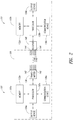
- FIG. 2 shows block diagrams of the first and second testing terminals 102a, 102b of the testing device 101.
- the first and second testing terminals 102a, 102b are shown in Figure 2 to be connected to the cabling installation 100.
- the first testing terminal 102a includes a processor 130a, memory 132a, an output device 134a, a communication device 136a and a transmitter 138 having a plurality of output terminals 142.
- the processor 130a is communicatively coupled to the memory 132a, output device 134a, communication device 136a and transmitter 138.
- the second testing terminal 102b includes a processor 130b, memory 132b, and output device 134b, a communication device 136b and a receiver 140.
- the processor 130b is communicatively coupled to the memory 132b, output device 134b, communication device 136b and receiver 140.
- the transmitter 138 of the first testing terminal 102a has a plurality of output terminals 142.
- the plurality of output terminals 142 are connected to the plurality of conductors 114, respectively, of the cabling installation 100 at a first end.
- the receiver 140 has a plurality of input terminals 144.
- the plurality of input terminals 144 are connected to the plurality of conductors 114, respectively, at a second end of the cabling installation 100 different than the first end. Because the first and second ends may be in different locations (for example, when installed), two terminals 102a, 102b of the testing device 101 are illustrated for a local and remote end, respectively. However, it is recognized that one device/terminal may have both the transmitter 138 and the receiver 140 or a transceiver. The device/terminal may transmit the first signal as a test signal and receive the second signal that is representative of the first signal having traversed a conductor 114.
- the processor 130a may be any type of device configured to execute executable instructions stored in the memory 132a. When the executable instructions are executed by the processor 130a, the executable instructions cause the processor 130a to perform the functions or techniques described herein.
- the processor 130a may be a controller, a microcontroller or a microprocessor, among others, and may include an arithmetic and logic unit (ALU), among other computational units.
- the processor 130a commands the transmitter 138 to transmit the first signal.
- the processor 130a also receives common mode insertion loss data detected by the second testing terminal 102b and determines based on the common mode insertion loss data whether the shield of the cabling installation 100 has a discontinuity as described herein. If so, the processor 130a determines a location of the discontinuity based on data obtained by the first or second terminal 102a, 102b.
- the processor 130a outputs, to the output device 134a, data indicative of the results of the performed testing. For example, the processor 130a may output data representative of whether the shield 116 is determined to be continuous (e.g., 'pass') or discontinuous (e.g., 'fail').
- the processor 102a may also determine a propagation delay for the cabling installation 100 based at least in part on a difference between a transmission time of the first signal and a reception time of the second signal.
- the memory 132a may be any device that is configured to store executable instructions.
- the memory 132a may also store data pertaining to the performed continuity testing, such as a test result, discontinuity location, propagation delay or common mode insertion loss data.
- the memory 132a may include a random access memory (RAM) and/or a read-only memory (ROM).
- the output device 134a may be any type of device configured to output data to a user.
- the output device 134a may be a display or a speaker, among others.
- the output device 134a may output, to a user, the results of shield continuity testing received from the processor 130a.
- the communication device 136a may be any device that is configured to communicate with another device and transmit data to or receive data from the other device.
- the other device may be the communication device 136b of the second testing terminal 102b.
- the communication device 136a may communicate using a wireless or wired communications protocol.
- the communication device 136a may be a modem or a transceiver.
- the communication device 136a receives data representative of the common mode insertion loss.
- the communication device 136a outputs the data to the processor 130a.
- the transmitter 138 may be any device configured to transmit a signal, whereby the signal may be a common mode test signal transmitted over the conductors 114 described herein.
- the transmitter 138 has the plurality of output terminals 142 described herein.
- the plurality of output terminals 142 are used to connect the testing device 101 to a cable or cabling installation under test.
- the transmitter 138 outputs the common mode signal over the plurality of output terminals 142 for transmission over the plurality of conductors 114.
- the processor 130b, memory 132b, output device 134b and communication device 136b are similar to the processor 130a, memory 132a, output device 134a and communication device 136a of the first testing terminal 102a described herein.
- the receiver 140 may be any device configured to receive the plurality of second signals.
- the receiver 140 has the plurality of input terminals 144 described herein.
- the receiver 140 receives, at the plurality of input terminals 144, the common mode signals transmitted over the plurality of conductors 114, respectively.
- the receiver 140 outputs data representative of the received second signals to the processor 130b.
- the processor 130b may evaluate the data to determine the common mode insertion loss or the propagation delay for the cabling installation 100. Alternatively or in addition, the processor 130b may cause the data to be output to the communication device 136b for transmission to the communication device 136a of the first terminal 102a and for evaluation by the processor 130a.
- testing terminals 102a, 102b Use of two testing terminals 102a, 102b is advantageous when the first and second ends of the conductors 114 are not in a proximity of each other. It is noted that although two testing terminals 102a, 102b are described herein as being respectively connected to two ends of the cabling installation 100, in various embodiments one testing terminal may be used.
- the testing terminal may have both input and output terminals 142, 144.
- the input and output terminals 142, 144 may be respectively connected to both ends of the conductors 114, particularly when both ends are in a proximity of each other, such as when the cable is in a cable reel or spool.
- Figure 3 shows a flow diagram of a method 300 for testing shield continuity.
- the testing device 101 performs a frequency sweep over a frequency range and, at each frequency point of a plurality of frequency points in the frequency range, transmits a first signal in common mode over a plurality of conductors 114 of a cable or a cabling installation, such as the cabling installation 100 described with reference to Figure 1 .
- the first signal is transmitted in common mode at the first end of the plurality of conductors 114, whereby the same first signal is transmitted over each conductor of the plurality of conductors 114.
- the plurality of conductors 114 are surrounded by the shield under test.
- the cable 106 or the cables 106 of the cabling installation 100 may, for example, be Datacomm cables having four twisted pairs 112 (and eight total conductors 114) with each twisted pair 112 is an independent transmission line.
- transmitting the first signal in common mode includes driving the plurality of conductors 114 simultaneously with the same first signal.
- all the conductors 114 of the plurality of twisted pairs 112 of the cable 106 may be driven simultaneously relative to the shield 116 with the same first signal.
- no one twisted pair 112 may remain not driven or neutral when the shield 116 is tested.
- the plurality of conductors 114 may be connected together and the first signal may be transmitted simultaneously over all of the plurality of conductors 114.
- the frequency range may be in a low frequency, such as 1 to 20 megahertz (MHz).
- the plurality of frequency points may be separated by 1 MHz from each other, whereby the frequency points may be 1, 2, 3, ..., 20 MHz.
- the first signal is transmitted simultaneously on the plurality of conductors 114.
- Low-frequency signals for example in the 1-20 MHz range, are advantageous in that when the shield surrounding the conductors 114 is discontinuous or broken, the first signal is impeded as it traverses the conductors 114. Conversely, if the shield is continuous, the first signal is relatively unimpeded. At relatively low frequencies, a signal having a larger magnitude is received at the second end of the conductors 114 when the shield is continuous than in the case when the shield is discontinuous. Particularly, an opening or breakage in the shield substantially blocks signal current from flowing in a loop formed by the shield and the conductors 114. The fact that a discontinuity impedes the first signal in the 1-20MHz range is advantageously used to facilitate discontinuity detection.
- the testing device 101 receives a plurality of second signals that are representative of the plurality of first signals, respectively, having traversed the respective plurality of conductors 114.
- the testing device 101 receives the plurality of second signals at the second ends of the plurality of conductors 114, respectively.
- the testing device 101 determines, based on the plurality of second signals, a common mode insertion loss at each frequency point of the plurality of frequency points in the frequency range.
- the testing device 101 also measures a propagation delay associated with the second signal of the plurality of second signals.
- the propagation delay may represent a duration of time between transmission of the first signal and reception of the second signal.
- the propagation delay is a function of a length of the cable or cabling installation 100 as longer cables or installations 100 are associated with longer traversal times.
- the testing device 101 may determine a common mode insertion loss for each twisted pair 112 of the plurality of twisted pairs.
- the testing device 101 may average the common mode insertion loss of the plurality of twisted pairs to determine the common mode insertion loss at 306 for the cabling installation 100.
- the determined common mode insertion loss may also be any function of a plurality of common mode insertion losses of the plurality of twisted pairs, respectively.
- the common mode signal levels for all twisted pairs 112 of the cable 116 are measured and averaged at the second end. In the event that the cable 106 is a Datacomm cable, four common mode signal levels are measured (one for each twisted pair 112) and averaged for determining the common mode insertion loss.
- the testing device 101 identifies a discontinuity in the cable or cabling installation based on the common mode insertion loss at 308. It is noted that in various embodiments, the second testing terminal 102b may send data representative of the common mode insertion loss to the first testing terminal 102a, by wired or wireless communication. The first testing terminal 102a may then determine whether there is a discontinuity in the cable or the cabling installation based on the data received from the second testing terminal 102b. Furthermore, in an embodiment the second testing terminal 102b sends data representative of the received plurality of second signals to the first testing terminal 102a, and the first testing terminal 102a determines the common mode insertion loss and identifies the discontinuity based on the plurality of second signals.
- the DC sneak path has a relatively high associated alternating current (AC) impedance.
- the testing device 101 transmits the first signals for testing the shield 116 over the conductors of the cabling installation. If the shield is open (or discontinuous) and the DC sneak path is present, the insertion loss is markedly different than had the shield been continuous.
- the techniques described herein detect shield discontinuity even when the DC sneak path is present and are not susceptible to (or present a false negative when) a DC sneak path is present.
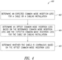
- Figure 4 shows a flow diagram of a method 400 for testing shield continuity.
- the testing device 101 determines an expected common mode insertion loss for a cable or a cabling installation.
- the expected common mode insertion loss may be determined based on (or as a function of) the propagation delay and/or the second signals received at the frequency points of the frequency sweep.
- the expected common mode insertion loss (in decibels (dB)) may be a linear function of the frequency and/or inversely correlated with the frequency. Because the propagation delay is a function of cable or cabling installation length, cables or cabling installations of different lengths have different expected common mode insertion loss profiles.
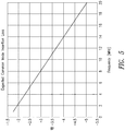
- Figure 5 shows an example of the expected common mode insertion loss for a cable or a cabling installation. Higher frequencies in the frequency range are associated with a lower expected common mode insertion loss.
- the example expected common mode insertion loss of Figure 5 is for a 50 meter (m) cable or cabling installation.
- the testing device 101 determines an offset common mode insertion loss based on the determined common mode insertion loss and the expected common mode insertion loss for the cable or cabling installation.
- the offset common mode insertion loss may be determined for each frequency point in the frequency range.
- the offset common mode insertion loss may be determined as a difference between the determined common mode insertion loss (at step 306) and the expected common mode insertion loss for the cable or cabling installation for each frequency point in the frequency range. If the determined common mode insertion loss and expected common mode insertion loss correspond to each other (for example, have close to a zero dB difference), the shield may be determined to be continuous. Alternatively, if the determined common mode insertion loss and expected common mode insertion loss do not correspond to each other, the shield may be determined to be discontinuous. At 406, the testing device 101 determines whether the shield is continuous based on the offset common mode insertion loss.
- Figure 6 shows examples of the expected and determined common mode insertion loss for two cables over a frequency range.
- the determined common mode insertion loss 604a largely corresponds with and tracks the expected common mode insertion loss 602a over the frequency range.
- the difference between the determined and expected common mode insertion losses 604a, 602a for the first cable is not larger than 2dB at any frequency point in the frequency range.
- the first cable may, thus, be determined to have a continuous shield.
- a determined common mode insertion loss 604b and the expected common mode insertion loss 602a a second cable diverge from each other over the frequency range.
- the difference between the determined and expected common mode insertion losses 604b, 602a for the second cable can be as much as 40dB. Accordingly, the second cable may, thus, be determined to have a discontinuous shield.
- the determined and expected common mode insertion losses may be compared over a segment (or a subrange) of the frequency range rather than the entirety of the frequency range. Further, a figure of merit may be used to quantify the difference between the determined and expected common mode insertion losses (i.e., the offset common mode insertion loss). The figure of merit may be compared to threshold to determine whether the shield is continuous with discontinuous.
- Figure 7 shows a flow diagram of a method 700 for testing shield continuity.
- the testing device 101 at 702 determines a segment of the frequency range over which to evaluate the offset common mode insertion loss.
- the segment of the frequency range may any portion of (for example, half of) the entire frequency range. For example, if the frequency range has twenty frequency points between 1 and 20MHz, the segment may be any ten consecutive frequency points between 1 and 20MHz.
- the segment may be determined based on the length of the cable or cabling installation under test (or the propagation delay associated with the cable or cabling installation). For example, a cable or cabling installation having a relatively short length, which is associated with a relatively short propagation delay, may have an associated segment that is closer to the end of the frequency range. Alternatively, a cable or cabling installation having a relatively long length (for example, having a propagation delay of at least 42 nanoseconds (ns)) may have an associated segment that is closer to the beginning of the frequency range.
- ns nanoseconds
- Figure 8 shows an example of frequency range segments in relation to propagation delays.
- the size of each frequency range segment is ten frequency points, which is half of the entire frequency range between 1 and 20 MHz.
- Each frequency range segment ranges between a starting frequency point 802 and an end frequency point 804. Cables or cabling installations that are longer than 50m (or have an associated propagation delay of 42ns or higher) are tested based on a frequency range segment that is at the lower end of the frequency range (or between 1 and 10MHz). Frequency points outside the frequency segment (for example, between 11 and 20MHz) are not used for testing the shields of the cables or cabling installations.
- the testing device 101 determines a figure of merit based on the offset common mode insertion loss in the segment of the frequency range.
- the figure of merit may be representative of deviation of the offset common mode insertion loss from a zero value.
- the figure of merit may be based on a standard deviation or a variance of the offset common mode insertion loss for a cable or cabling installation. A higher variance represents larger deviations from the expected common mode insertion loss and is consequently indicative of a discontinuity in the shield.
- ⁇ OCMIL is the mean of the offset common mode insertion loss over the segment of the frequency range.
- ⁇ OCMIL in Equation (1) may represent a standard deviation of the difference between the offset common mode insertion loss over the segment of the frequency range ( OCMIL(f) ) and a least mean squares (LMS) fit for the offset common mode insertion loss over the segment ( LMSOCMIL(f) ).
- the testing device 101 compares the figure of merit to one or more thresholds at 706 and determines, at 708, whether the shield is continuous based on comparing the figure of merit to the one or more thresholds. For example, if the figure of merit is greater than a threshold, the testing device 101 may deem the shield of the cable or cabling installation to be continuous. Conversely, if the figure of merit is less than the threshold, the testing device 101 may deem the shield of the cable or cabling installation to be discontinuous.
- the testing device 101 may identify a location of the discontinuity based on common mode return loss data for the cable or cabling installation.
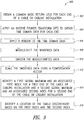
- Figure 9 shows a method 900 for determining a location of a discontinuity in a cable or cabling installation.
- the testing device 101 obtains, at 902, a common mode return loss for each end of a cable or cabling installation.
- the testing device 101 applies an inverse Fourier Transform (IFT) to the common mode return loss to obtain time domain data for each end.
- the IFT may be an inverse Fast Fourier Transform (IFFT) having any size.
- IFFT a 301-point IFFT in steps of 1MHz.
- the testing device 101 applies a window to the time domain data.
- the window may, for example, be a Blackman window.
- the testing device 101 modulo-shifts the windowed data at 908.
- the testing device 101 may modulo-shift the windowed data using any number of points, such as ten points.
- the testing device 101 then smooths the modulo-shifted data at 910. For example, a bi-directional moving-average filter having a boxcar width of four may be used to smooth the modulo-shifted data.
- the testing device 101 scales the smoothed data using a compensation vector at 912. Scaling the smoothed data may include multiplying the data with a predetermined attenuation compensation vector to compensate for a reflected pulse's level variation with distance.
- the testing device 101 identifies a first global maximum and an associated first index for a first end of the cable or cabling installation and a second global maximum and an associated second index for a second end of the cable or cabling installation.
- the testing device 101 identifies a location of the shield discontinuity based on the first index and the second index at 916. For example, a spike in the scaled data may indicate a shield discontinuity. The location of the discontinuity corresponds to the index of the spike in the scaled time-domain data.
- a location of the index in the compensated data corresponds to a location of the discontinuity in the cable. For example, if the index is at the center of the compensated data, the discontinuity is determined to be at the center of the cable.
Landscapes
- Physics & Mathematics (AREA)
- General Physics & Mathematics (AREA)
- Electromagnetism (AREA)
- Testing Of Short-Circuits, Discontinuities, Leakage, Or Incorrect Line Connections (AREA)
- Locating Faults (AREA)
Abstract
Description
- This application is directed to a method and apparatus for detecting shield continuity in a cable or a cabling installation based on common mode insertion loss and, in particular, insertion loss of signals transmitted in common mode over one or more twisted pairs of conductors of the cable or cabling installation.
- Electrical cables include shields that reduce electromagnetic interference of an outside environment that can reach conductors of a cable. The cables may be twisted pairs of conductors. Discontinuities in the shield, which may manifest as a break or tear in the shield, degrade the crosstalk (XT) performance of the cable. Direct current (DC) verification techniques of shield continuity are prone to yield a false positive test result (i.e., 'pass' a discontinuous shield) when the shield is grounded. Further, the presence of a parasitic inductance, for example, due to shield termination at a connector, may cause shield verification techniques to yield a false negative test result (i.e., 'fail' a continuous shield).
- In an embodiment, a shield continuity testing device includes a transmitter configured to transmit a first signal in common mode over a plurality of conductors of a cable or cabling installation having a shield. In an embodiment, the transmitter is configured to transmit the first signal in the common mode at a first end of the plurality of conductors. In an embodiment, a shield continuity testing device includes a receiver configured to receive a plurality of second signals representative of the first signal at a second end of the plurality of conductors, respectively, and output data representative of the plurality of second signals. In an embodiment, a shield continuity testing device includes a processor configured to: receive the data representative of the plurality of second signals; determine a common mode insertion loss for the cable or cabling installation based on the plurality of second signals; determine, based on the common mode insertion loss, whether the shield is continuous or discontinuous; and output data representative of whether the shield is continuous or discontinuous.
- In an embodiment, the first signal spans a frequency range, and the transmitter is configured to transmit the first signal at a plurality of frequency points in the frequency range. In an embodiment, the processor is configured to determine the common mode insertion loss by at least: determining, based on the plurality of second signals, the common mode insertion loss at each frequency point of the plurality of frequency points in the frequency range. In an embodiment, the frequency range is between 1 and 20 megahertz (MHz). In an embodiment, the processor is configured to determine whether the shield is continuous or discontinuous by at least: determining an expected common mode insertion loss for the cable or cabling installation; determining an offset common mode insertion loss as a difference between the expected common mode insertion loss and the determined common mode insertion loss; and determining whether the shield is continuous or discontinuous based on the offset common mode insertion loss.
- In an embodiment, the processor is configured to determine whether the shield is continuous or discontinuous by at least: determining a figure of merit for the offset common mode insertion loss; and comparing the figure of merit to a threshold. In an embodiment, the processor is configured to determine the figure of merit by at least: determining a mean of the offset common mode insertion loss over a plurality of frequency points in a frequency range over which the first signal is transmitted; determining a standard deviation of a difference between the offset common mode insertion loss over the plurality of frequency points and a least mean square fit of the offset common mode insertion loss over the plurality of frequency points; and determining the figure of merit as a difference between the mean and the standard deviation.
- In an embodiment, the processor is configured to determine that the shield is continuous if the figure of merit is greater than or equal to the threshold and determine that the shield is discontinuous if the figure of merit is less than the threshold. In an embodiment, the processor is configured to determine whether the shield is continuous or discontinuous based on the common mode insertion loss in a subrange of the frequency range over which the first signal is transmitted. In an embodiment, the processor is configured to: identify the subrange based on a determined signal propagation delay of the cable or cabling installation.
- In an embodiment, a location of the subrange in the frequency range is inversely correlated to the propagation delay such that an increase in the propagation delay results in shifting the subrange towards a beginning of the frequency range and a decrease in the propagation delay results in shifting the subrange towards an end of the frequency range. In an embodiment, the plurality of conductors of the cable or the cabling installation have a twisted pair arrangement in which a pair of conductors of the plurality of conductors are pair-wise twisted around each other. In an embodiment, a shield continuity testing device includes an output device, communicatively coupled to the processor, configured to receive the data representative of whether the shield is continuous or discontinuous, and output an indication of whether the shield is continuous or discontinuous.
- In an embodiment, the processor is configured to determine a location of a discontinuity of the shield by at least: determining a common mode return loss for the cable or cabling installation; applying a Fourier transform to the common mode return loss to obtain time domain data; scaling the time domain data using a compensation vector; determining an index associated with a maximum of the scaled time domain data; and determining the location of the discontinuity along the cable or cabling installation based on the index associated with the maximum of the scaled time domain data. In an embodiment, a relative location of the index in the scaled time domain data corresponds to the relative location of the discontinuity in the shield.
- In an embodiment, a method for testing shield continuity includes transmitting a first signal in common mode over a plurality of conductors of a cable or a cabling installation having a shield, the first signal in the common mode at a first end of the plurality of conductors; receiving a plurality of second signals representative of the first signal at a second end of the plurality of conductors, respectively; determining a common mode insertion loss for the cable or cabling installation based on the plurality of second signals; determining, based on the common mode insertion loss, whether the shield is continuous or discontinuous; and outputting data representative of whether the shield is continuous or discontinuous.
- In an embodiment, a method includes transmitting the first signal over a plurality of frequency points in a frequency range. In an embodiment, a method includes determining, based on the plurality of second signals, the common mode insertion loss at each frequency point of the plurality of frequency points in the frequency range. In an embodiment, the frequency range is between 1 and 20 megahertz (MHz). In an embodiment, a method includes determining an expected common mode insertion loss for the cable or cabling installation; determining an offset common mode insertion loss as a difference between the expected common mode insertion loss and the determined common mode insertion loss; and determining whether the shield is continuous or discontinuous based on the offset common mode insertion loss.
- In an embodiment, a method includes determining a mean of the offset common mode insertion loss over a plurality of frequency points in a frequency range over which the first signal is transmitted; determining a standard deviation of a difference between the offset common mode insertion loss over the plurality of frequency points and a least mean square fit of the offset common mode insertion loss over the plurality of frequency points; determining a figure of merit as a difference between the mean and the standard deviation; and determining that the shield is continuous if the figure of merit is greater than or equal to a threshold and determine that the shield is discontinuous if the figure of merit is less than the threshold. In an embodiment, a method includes determining a common mode return loss for the cable or cabling installation; applying an inverse Fourier transform to the common mode return loss to obtain time domain data; scaling the time domain data using a compensation vector; determining an index associated with a maximum of the scaled time domain data; and determining a location of a discontinuity along the cable or cabling installation based on the index associated with the maximum of the scaled time domain data.
-
-
Figure 1 shows a cabling installation under test coupled to a testing device. -
Figure 2 shows block diagrams of first and second testing terminals of the testing device. -
Figure 3 shows a flow diagram of a method for testing shield continuity. -
Figure 4 shows a flow diagram of a method for testing shield continuity. -
Figure 5 shows an example of an expected common mode insertion loss for a cable or a cabling installation. -
Figure 6 shows examples of the expected and determined common mode insertion loss for two cables over a frequency range. -
Figure 7 shows a flow diagram of a method for testing shield continuity. -
Figure 8 shows an example of frequency range segments in relation to propagation delays. -
Figure 9 shows a method for determining a location of a discontinuity in a cable or cabling installation. -
Figure 1 shows acabling installation 100 under test coupled to atesting device 101. The testing device includes afirst testing terminal 102a and asecond testing terminal 102b. Thecabling installation 100 includes afirst cable 106a and asecond cable 106b (collectively referred to herein by the numeral alone) connected together using aconnector plug 108 and aconnector jack 110. It is noted that although acabling installation 100 including multiple cables 106 is described with reference toFigure 1 , the techniques described herein may be used for testing an installation with any number of cables or for testing one cable. - Each cable 106 includes a plurality of twisted pairs of
conductors 112. Eachpair 112 includes afirst conductor 114a and a second conductor 114b twisted around each other to reduce electromagnetic radiation and crosstalk and improve external electromagnetic interference rejection. Although the plurality of twisted pairs are shown inFigure 1 to include four pairs, it is noted that a cable 106 may have any number of conductors or pairs thereof. The conductor 114 may each be insulated with an insulator (not shown). - The plurality of
twisted pairs 112 are shielded by ashield 116. Theshield 116 surrounds the plurality oftwisted pairs 112 over a length of the cable 106. Theshield 116, which may be foil, provides an electrically conductive barrier to shield the conductors 114 from external electromagnetic waves. The cable 106 also has aninsulator 118. - It is desirable for the
shield 116 to be continuous without breakages or discontinuities. Adiscontinuity 120 in theshield 116 allows electromagnetic interference to reach thetwisted pairs 112 and, consequently, degrades crosstalk (XT) performance of the cable 106, among other undesirable consequences. - In addition, the
shield 116 of thecabling installation 100 may connected to aground 122 at one or more points in thecabling installation 100. The ground connections may hinder direct current (DC) based shield verification techniques ofshield 116 continuity by providing a parallel 'sneak' path for current applied to the shield. The parallel 'sneak' path bypasses thediscontinuity 120, yielding a low resistance value and resulting in a false 'pass' in a DC-based verification technique. - The
shield 116 may also have adrain wire 124 having a parasitic inductance. Thesecond cable 106b of thecabling installation 100 is shown to be terminated at theconnector jack 110 using thedrain wire 124. Use of thedrain wire 124 maintains continuity of theshield 116 through thecabling installation 100. However, unartful or unskillful termination of thesecond cable 106b (or any constituent cable 106) may result in thedrain wire 124 having a parasitic inductance (for example, as a result of thedrain wire 124 being several inches long or looping around itself). Thedrain wire 124 parasitic inductance may result in a false fail in common mode return loss shield verification techniques. Such techniques may declare theshield 116 to have a discontinuity when in fact theshield 116 is continuous, albeit having an unartfully- or unskillfully-terminateddrain wire 124 that results in a relatively large parasitic inductance.U.S. Patent No. 8,570,049 , which is incorporated herein by reference in its entirety, describes common mode return loss-based testing of shield continuity. - As shown in
Figure 1 , thefirst testing terminal 102a and thesecond testing terminal 102b of thetesting device 101 are coupled to thecabling installation 100. Thefirst testing terminal 102a may be a main instrument, and thesecond testing terminal 102b may be a remote instrument of thetesting device 101. Thesecond testing terminal 102b may be disposed in a location different than that of thefirst testing terminal 102a. In particular, thefirst testing terminal 102a is coupled to a first end of the conductors of the plurality oftwisted pairs 112. Thesecond testing terminal 102b is coupled to a second end of the conductors of the plurality oftwisted pairs 112. Thefirst testing terminal 102a performs a common mode sweep over a frequency range. At each frequency point over the plurality of frequency points in the sweep, thefirst testing terminal 102a transmits, at the first end of the conductors 114 of the plurality oftwisted pairs 112, a first signal in common mode. In the common mode, the same first signal is transmitted over each conductor 114 of thecabling installation 100. The common mode signal traverses the conductors 114 of theinstallation 100. - The
second testing terminal 102b receives a second signal at the second end of each conductor 114 of the plurality oftwisted pairs 112. The second signal is representative of the first signal having undergone insertion loss as it traversed the conductor 114. The first orsecond testing terminal twisted pairs 112. Further, the first orsecond testing terminal shield 116. The first orsecond testing terminal -
Figure 2 shows block diagrams of the first andsecond testing terminals testing device 101. The first andsecond testing terminals Figure 2 to be connected to thecabling installation 100. Thefirst testing terminal 102a includes aprocessor 130a,memory 132a, anoutput device 134a, acommunication device 136a and atransmitter 138 having a plurality ofoutput terminals 142. Theprocessor 130a is communicatively coupled to thememory 132a,output device 134a,communication device 136a andtransmitter 138. Thesecond testing terminal 102b includes aprocessor 130b,memory 132b, andoutput device 134b, acommunication device 136b and areceiver 140. Theprocessor 130b is communicatively coupled to thememory 132b,output device 134b,communication device 136b andreceiver 140. - The
transmitter 138 of thefirst testing terminal 102a has a plurality ofoutput terminals 142. The plurality ofoutput terminals 142 are connected to the plurality of conductors 114, respectively, of thecabling installation 100 at a first end. Thereceiver 140 has a plurality ofinput terminals 144. The plurality ofinput terminals 144 are connected to the plurality of conductors 114, respectively, at a second end of thecabling installation 100 different than the first end. Because the first and second ends may be in different locations (for example, when installed), twoterminals testing device 101 are illustrated for a local and remote end, respectively. However, it is recognized that one device/terminal may have both thetransmitter 138 and thereceiver 140 or a transceiver. The device/terminal may transmit the first signal as a test signal and receive the second signal that is representative of the first signal having traversed a conductor 114. - The
processor 130a may be any type of device configured to execute executable instructions stored in thememory 132a. When the executable instructions are executed by theprocessor 130a, the executable instructions cause theprocessor 130a to perform the functions or techniques described herein. Theprocessor 130a may be a controller, a microcontroller or a microprocessor, among others, and may include an arithmetic and logic unit (ALU), among other computational units. Theprocessor 130a commands thetransmitter 138 to transmit the first signal. Theprocessor 130a also receives common mode insertion loss data detected by thesecond testing terminal 102b and determines based on the common mode insertion loss data whether the shield of thecabling installation 100 has a discontinuity as described herein. If so, theprocessor 130a determines a location of the discontinuity based on data obtained by the first or second terminal 102a, 102b. - The
processor 130a outputs, to theoutput device 134a, data indicative of the results of the performed testing. For example, theprocessor 130a may output data representative of whether theshield 116 is determined to be continuous (e.g., 'pass') or discontinuous (e.g., 'fail'). Theprocessor 102a may also determine a propagation delay for thecabling installation 100 based at least in part on a difference between a transmission time of the first signal and a reception time of the second signal. - The
memory 132a may be any device that is configured to store executable instructions. Thememory 132a may also store data pertaining to the performed continuity testing, such as a test result, discontinuity location, propagation delay or common mode insertion loss data. Thememory 132a may include a random access memory (RAM) and/or a read-only memory (ROM). Theoutput device 134a may be any type of device configured to output data to a user. For example, theoutput device 134a may be a display or a speaker, among others. Theoutput device 134a may output, to a user, the results of shield continuity testing received from theprocessor 130a. - The
communication device 136a may be any device that is configured to communicate with another device and transmit data to or receive data from the other device. The other device may be thecommunication device 136b of thesecond testing terminal 102b. Thecommunication device 136a may communicate using a wireless or wired communications protocol. For example, thecommunication device 136a may be a modem or a transceiver. Thecommunication device 136a receives data representative of the common mode insertion loss. Thecommunication device 136a outputs the data to theprocessor 130a. - The
transmitter 138 may be any device configured to transmit a signal, whereby the signal may be a common mode test signal transmitted over the conductors 114 described herein. Thetransmitter 138 has the plurality ofoutput terminals 142 described herein. The plurality ofoutput terminals 142 are used to connect thetesting device 101 to a cable or cabling installation under test. Thetransmitter 138 outputs the common mode signal over the plurality ofoutput terminals 142 for transmission over the plurality of conductors 114. - In the
second testing terminal 102b, theprocessor 130b,memory 132b,output device 134b andcommunication device 136b are similar to theprocessor 130a,memory 132a,output device 134a andcommunication device 136a of thefirst testing terminal 102a described herein. Thereceiver 140 may be any device configured to receive the plurality of second signals. Thereceiver 140 has the plurality ofinput terminals 144 described herein. Thereceiver 140 receives, at the plurality ofinput terminals 144, the common mode signals transmitted over the plurality of conductors 114, respectively. - The
receiver 140 outputs data representative of the received second signals to theprocessor 130b. Theprocessor 130b may evaluate the data to determine the common mode insertion loss or the propagation delay for thecabling installation 100. Alternatively or in addition, theprocessor 130b may cause the data to be output to thecommunication device 136b for transmission to thecommunication device 136a of thefirst terminal 102a and for evaluation by theprocessor 130a. - Use of two
testing terminals testing terminals cabling installation 100, in various embodiments one testing terminal may be used. For example, the testing terminal may have both input andoutput terminals output terminals -
Figure 3 shows a flow diagram of amethod 300 for testing shield continuity. In themethod 300, thetesting device 101, at 302, performs a frequency sweep over a frequency range and, at each frequency point of a plurality of frequency points in the frequency range, transmits a first signal in common mode over a plurality of conductors 114 of a cable or a cabling installation, such as thecabling installation 100 described with reference toFigure 1 . The first signal is transmitted in common mode at the first end of the plurality of conductors 114, whereby the same first signal is transmitted over each conductor of the plurality of conductors 114. The plurality of conductors 114 are surrounded by the shield under test. - The cable 106 or the cables 106 of the
cabling installation 100 may, for example, be Datacomm cables having four twisted pairs 112 (and eight total conductors 114) with eachtwisted pair 112 is an independent transmission line. As described herein, transmitting the first signal in common mode includes driving the plurality of conductors 114 simultaneously with the same first signal. For example, all the conductors 114 of the plurality oftwisted pairs 112 of the cable 106 may be driven simultaneously relative to theshield 116 with the same first signal. In an embodiment, no onetwisted pair 112 may remain not driven or neutral when theshield 116 is tested. For example, at the first end, the plurality of conductors 114 may be connected together and the first signal may be transmitted simultaneously over all of the plurality of conductors 114. - The frequency range may be in a low frequency, such as 1 to 20 megahertz (MHz). The plurality of frequency points may be separated by 1 MHz from each other, whereby the frequency points may be 1, 2, 3, ..., 20 MHz. The first signal is transmitted simultaneously on the plurality of conductors 114.
- Low-frequency signals, for example in the 1-20 MHz range, are advantageous in that when the shield surrounding the conductors 114 is discontinuous or broken, the first signal is impeded as it traverses the conductors 114. Conversely, if the shield is continuous, the first signal is relatively unimpeded. At relatively low frequencies, a signal having a larger magnitude is received at the second end of the conductors 114 when the shield is continuous than in the case when the shield is discontinuous. Particularly, an opening or breakage in the shield substantially blocks signal current from flowing in a loop formed by the shield and the conductors 114. The fact that a discontinuity impedes the first signal in the 1-20MHz range is advantageously used to facilitate discontinuity detection.
- At 304, the
testing device 101, receives a plurality of second signals that are representative of the plurality of first signals, respectively, having traversed the respective plurality of conductors 114. Thetesting device 101 receives the plurality of second signals at the second ends of the plurality of conductors 114, respectively. At 306, thetesting device 101 determines, based on the plurality of second signals, a common mode insertion loss at each frequency point of the plurality of frequency points in the frequency range. Thetesting device 101 also measures a propagation delay associated with the second signal of the plurality of second signals. The propagation delay may represent a duration of time between transmission of the first signal and reception of the second signal. The propagation delay is a function of a length of the cable orcabling installation 100 as longer cables orinstallations 100 are associated with longer traversal times. - The
testing device 101 may determine a common mode insertion loss for eachtwisted pair 112 of the plurality of twisted pairs. Thetesting device 101 may average the common mode insertion loss of the plurality of twisted pairs to determine the common mode insertion loss at 306 for thecabling installation 100. The determined common mode insertion loss may also be any function of a plurality of common mode insertion losses of the plurality of twisted pairs, respectively. The common mode signal levels for alltwisted pairs 112 of thecable 116 are measured and averaged at the second end. In the event that the cable 106 is a Datacomm cable, four common mode signal levels are measured (one for each twisted pair 112) and averaged for determining the common mode insertion loss. - The
testing device 101 identifies a discontinuity in the cable or cabling installation based on the common mode insertion loss at 308. It is noted that in various embodiments, thesecond testing terminal 102b may send data representative of the common mode insertion loss to thefirst testing terminal 102a, by wired or wireless communication. Thefirst testing terminal 102a may then determine whether there is a discontinuity in the cable or the cabling installation based on the data received from thesecond testing terminal 102b. Furthermore, in an embodiment thesecond testing terminal 102b sends data representative of the received plurality of second signals to thefirst testing terminal 102a, and thefirst testing terminal 102a determines the common mode insertion loss and identifies the discontinuity based on the plurality of second signals. - It is noted that when a low resistance DC sneak path is present due to grounding the shield as described with reference to
Figure 1 , the DC sneak path has a relatively high associated alternating current (AC) impedance. Thetesting device 101 transmits the first signals for testing theshield 116 over the conductors of the cabling installation. If the shield is open (or discontinuous) and the DC sneak path is present, the insertion loss is markedly different than had the shield been continuous. The techniques described herein detect shield discontinuity even when the DC sneak path is present and are not susceptible to (or present a false negative when) a DC sneak path is present. -
Figure 4 shows a flow diagram of amethod 400 for testing shield continuity. In themethod 400, at 402, thetesting device 101 determines an expected common mode insertion loss for a cable or a cabling installation. The expected common mode insertion loss may be determined based on (or as a function of) the propagation delay and/or the second signals received at the frequency points of the frequency sweep. The expected common mode insertion loss (in decibels (dB)) may be a linear function of the frequency and/or inversely correlated with the frequency. Because the propagation delay is a function of cable or cabling installation length, cables or cabling installations of different lengths have different expected common mode insertion loss profiles.Figure 5 shows an example of the expected common mode insertion loss for a cable or a cabling installation. Higher frequencies in the frequency range are associated with a lower expected common mode insertion loss. The example expected common mode insertion loss ofFigure 5 is for a 50 meter (m) cable or cabling installation. - At 404, the
testing device 101 determines an offset common mode insertion loss based on the determined common mode insertion loss and the expected common mode insertion loss for the cable or cabling installation. The offset common mode insertion loss may be determined for each frequency point in the frequency range. The offset common mode insertion loss may be determined as a difference between the determined common mode insertion loss (at step 306) and the expected common mode insertion loss for the cable or cabling installation for each frequency point in the frequency range. If the determined common mode insertion loss and expected common mode insertion loss correspond to each other (for example, have close to a zero dB difference), the shield may be determined to be continuous. Alternatively, if the determined common mode insertion loss and expected common mode insertion loss do not correspond to each other, the shield may be determined to be discontinuous. At 406, thetesting device 101 determines whether the shield is continuous based on the offset common mode insertion loss. -
Figure 6 shows examples of the expected and determined common mode insertion loss for two cables over a frequency range. For a first cable, the determined commonmode insertion loss 604a largely corresponds with and tracks the expected commonmode insertion loss 602a over the frequency range. The difference between the determined and expected commonmode insertion losses mode insertion loss 604b and the expected commonmode insertion loss 602a a second cable diverge from each other over the frequency range. The difference between the determined and expected commonmode insertion losses - The determined and expected common mode insertion losses may be compared over a segment (or a subrange) of the frequency range rather than the entirety of the frequency range. Further, a figure of merit may be used to quantify the difference between the determined and expected common mode insertion losses (i.e., the offset common mode insertion loss). The figure of merit may be compared to threshold to determine whether the shield is continuous with discontinuous.
-
Figure 7 shows a flow diagram of amethod 700 for testing shield continuity. In themethod 700, thetesting device 101 at 702 determines a segment of the frequency range over which to evaluate the offset common mode insertion loss. The segment of the frequency range may any portion of (for example, half of) the entire frequency range. For example, if the frequency range has twenty frequency points between 1 and 20MHz, the segment may be any ten consecutive frequency points between 1 and 20MHz. - The segment may be determined based on the length of the cable or cabling installation under test (or the propagation delay associated with the cable or cabling installation). For example, a cable or cabling installation having a relatively short length, which is associated with a relatively short propagation delay, may have an associated segment that is closer to the end of the frequency range. Alternatively, a cable or cabling installation having a relatively long length (for example, having a propagation delay of at least 42 nanoseconds (ns)) may have an associated segment that is closer to the beginning of the frequency range.
-
Figure 8 shows an example of frequency range segments in relation to propagation delays. The size of each frequency range segment is ten frequency points, which is half of the entire frequency range between 1 and 20 MHz. Each frequency range segment ranges between a startingfrequency point 802 and anend frequency point 804. Cables or cabling installations that are longer than 50m (or have an associated propagation delay of 42ns or higher) are tested based on a frequency range segment that is at the lower end of the frequency range (or between 1 and 10MHz). Frequency points outside the frequency segment (for example, between 11 and 20MHz) are not used for testing the shields of the cables or cabling installations. - Referring back to
Figure 7 , at 704, thetesting device 101 determines a figure of merit based on the offset common mode insertion loss in the segment of the frequency range. The figure of merit may be representative of deviation of the offset common mode insertion loss from a zero value. The figure of merit may be based on a standard deviation or a variance of the offset common mode insertion loss for a cable or cabling installation. A higher variance represents larger deviations from the expected common mode insertion loss and is consequently indicative of a discontinuity in the shield. - In an embodiment, the figure of merit may be represented as:


Figure 8 ) and OCMIL(f)) is the offset common mode insertion loss over the segment of the frequency range. σOCMIL in Equation (1) may represent a standard deviation of the difference between the offset common mode insertion loss over the segment of the frequency range (OCMIL(f)) and a least mean squares (LMS) fit for the offset common mode insertion loss over the segment (LMSOCMIL(f)). The standard deviation may be determined as:
- The variation in the offset common mode insertion loss over the segment is negatively correlated with the figure of merit. A relatively large figure of merit is indicative of shield continuity, whereas a relatively small figure of merit indicates that the shield has a discontinuity.
- The
testing device 101 compares the figure of merit to one or more thresholds at 706 and determines, at 708, whether the shield is continuous based on comparing the figure of merit to the one or more thresholds. For example, if the figure of merit is greater than a threshold, thetesting device 101 may deem the shield of the cable or cabling installation to be continuous. Conversely, if the figure of merit is less than the threshold, thetesting device 101 may deem the shield of the cable or cabling installation to be discontinuous. - If the shield is determined to be discontinuous, the
testing device 101 may identify a location of the discontinuity based on common mode return loss data for the cable or cabling installation. -
Figure 9 shows amethod 900 for determining a location of a discontinuity in a cable or cabling installation. In themethod 900, thetesting device 101 obtains, at 902, a common mode return loss for each end of a cable or cabling installation. At 904, thetesting device 101 applies an inverse Fourier Transform (IFT) to the common mode return loss to obtain time domain data for each end. The IFT may be an inverse Fast Fourier Transform (IFFT) having any size. For example, the IFFT may be a 301-point IFFT in steps of 1MHz. At 906, thetesting device 101 applies a window to the time domain data. The window may, for example, be a Blackman window. - The
testing device 101 modulo-shifts the windowed data at 908. Thetesting device 101 may modulo-shift the windowed data using any number of points, such as ten points. Thetesting device 101 then smooths the modulo-shifted data at 910. For example, a bi-directional moving-average filter having a boxcar width of four may be used to smooth the modulo-shifted data. - The
testing device 101 scales the smoothed data using a compensation vector at 912. Scaling the smoothed data may include multiplying the data with a predetermined attenuation compensation vector to compensate for a reflected pulse's level variation with distance. At 914, thetesting device 101 identifies a first global maximum and an associated first index for a first end of the cable or cabling installation and a second global maximum and an associated second index for a second end of the cable or cabling installation. Thetesting device 101 identifies a location of the shield discontinuity based on the first index and the second index at 916. For example, a spike in the scaled data may indicate a shield discontinuity. The location of the discontinuity corresponds to the index of the spike in the scaled time-domain data. For example, a location of the index in the compensated data, which is time domain data, corresponds to a location of the discontinuity in the cable. For example, if the index is at the center of the compensated data, the discontinuity is determined to be at the center of the cable. - The various embodiments described above can be combined to provide further embodiments. These and other changes can be made to the embodiments in light of the above-detailed description. In general, in the following claims, the terms used should not be construed to limit the claims to the specific embodiments disclosed in the specification and the claims, but should be construed to include all possible embodiments along with the full scope of equivalents to which such claims are entitled. Accordingly, the claims are not limited by the disclosure.
Claims (15)
- A shield continuity testing device, comprising:a transmitter configured to transmit a first signal in common mode over a plurality of conductors of a cable or cabling installation having a shield, the transmitter being configured to transmit the first signal in the common mode at a first end of the plurality of conductors;a receiver configured to receive a plurality of second signals representative of the first signal at a second end of the plurality of conductors, respectively, and output data representative of the plurality of second signals; anda processor configured to:receive the data representative of the plurality of second signals;determine a common mode insertion loss for the cable or cabling installation based on the plurality of second signals;determine, based on the common mode insertion loss, whether the shield is continuous or discontinuous; andoutput data representative of whether the shield is continuous or discontinuous.
- The shield continuity testing device of claim 1, wherein the first signal spans a frequency range, and the transmitter is configured to transmit the first signal at a plurality of frequency points in the frequency range; and
optionally, wherein the frequency range is between 1 and 20 megahertz, MHz. - The shield continuity testing device of claim 2, wherein the processor is configured to determine the common mode insertion loss by at least:
determining, based on the plurality of second signals, the common mode insertion loss at each frequency point of the plurality of frequency points in the frequency range. - The shield continuity testing device of any of claims 1 to 3, wherein the processor is configured to determine whether the shield is continuous or discontinuous by at least:determining an expected common mode insertion loss for the cable or cabling installation;determining an offset common mode insertion loss as a difference between the expected common mode insertion loss and the determined common mode insertion loss; anddetermining whether the shield is continuous or discontinuous based on the offset common mode insertion loss.
- The shield continuity testing device of claim 4, wherein the processor is further configured to determine whether the shield is continuous or discontinuous by at least:determining a figure of merit for the offset common mode insertion loss;comparing the figure of merit to a threshold; andoptionally, wherein the processor is configured to determine the figure of merit by at least:determining a mean of the offset common mode insertion loss over a plurality of frequency points in a frequency range over which the first signal is transmitted;determining a standard deviation of a difference between the offset common mode insertion loss over the plurality of frequency points and a least mean square fit of the offset common mode insertion loss over the plurality of frequency points;determining the figure of merit as a difference between the mean and the standard deviation; andoptionally, wherein the processor is configured to determine that the shield is continuous if the figure of merit is greater than or equal to the threshold and determine that the shield is discontinuous if the figure of merit is less than the threshold.
- The shield continuity testing device of any of claims 1 to 5, wherein the processor is configured to determine whether the shield is continuous or discontinuous based on the common mode insertion loss in a subrange of the frequency range over which the first signal is transmitted, and wherein the processor is configured to:identify the subrange based on a determined signal propagation delay of the cable or cabling installation; andoptionally, wherein a location of the subrange in the frequency range is inversely correlated to the propagation delay such that an increase in the propagation delay results in shifting the subrange towards a beginning of the frequency range and a decrease in the propagation delay results in shifting the subrange towards an end of the frequency range.
- The shield continuity testing device of any of claims 1 to 6, wherein the plurality of conductors of the cable or the cabling installation have a twisted pair arrangement in which a pair of conductors of the plurality of conductors are pair-wise twisted around each other.
- The shield continuity testing device of any of claims 1 to 7, comprising:
an output device, communicatively coupled to the processor, configured to receive the data representative of whether the shield is continuous or discontinuous, and output an indication of whether the shield is continuous or discontinuous. - The shield continuity testing device of any of claims 1 to 8, wherein the processor is configured to determine a location of a discontinuity of the shield by at least:determining a common mode return loss for the cable or cabling installation;applying a Fourier transform to the common mode return loss to obtain time domain data;scaling the time domain data using a compensation vector;determining an index associated with a maximum of the scaled time domain data; anddetermining the location of the discontinuity along the cable or cabling installation based on the index associated with the maximum of the scaled time domain data;and optionally, wherein a relative location of the index in the scaled time domain data corresponds to the relative location of the discontinuity in the shield.
- A method for testing shield continuity, comprising:transmitting a first signal in common mode over a plurality of conductors of a cable or a cabling installation having a shield, the first signal in the common mode at a first end of the plurality of conductors;receiving a plurality of second signals representative of the first signal at a second end of the plurality of conductors, respectively;determining a common mode insertion loss for the cable or cabling installation based on the plurality of second signals;determining, based on the common mode insertion loss, whether the shield is continuous or discontinuous; andoutputting data representative of whether the shield is continuous or discontinuous.
- The method of claim 10, further comprising:transmitting the first signal over a plurality of frequency points in a frequency range.
- The method of any of claims 10 or 11, further comprising:
determining, based on the plurality of second signals, the common mode insertion loss at each frequency point of the plurality of frequency points in the frequency range, wherein the frequency range is between 1 and 20 megahertz, MHz. - The method of any of claims 10 to 12, further comprising:determining an expected common mode insertion loss for the cable or cabling installation;determining an offset common mode insertion loss as a difference between the expected common mode insertion loss and the determined common mode insertion loss; anddetermining whether the shield is continuous or discontinuous based on the offset common mode insertion loss.
- The method of claim 13, further comprising:determining a mean of the offset common mode insertion loss over a plurality of frequency points in a frequency range over which the first signal is transmitted;determining a standard deviation of a difference between the offset common mode insertion loss over the plurality of frequency points and a least mean square fit of the offset common mode insertion loss over the plurality of frequency points;determining a figure of merit as a difference between the mean and the standard deviation; anddetermining that the shield is continuous if the figure of merit is greater than or equal to a threshold and determine that the shield is discontinuous if the figure of merit is less than the threshold.
- The method of any of claims 10 to 14, further comprising:determining a common mode return loss for the cable or cabling installation;applying an inverse Fourier transform to the common mode return loss to obtain time domain data;scaling the time domain data using a compensation vector;determining an index associated with a maximum of the scaled time domain data; anddetermining a location of a discontinuity along the cable or cabling installation based on the index associated with the maximum of the scaled time domain data.
Applications Claiming Priority (1)
| Application Number | Priority Date | Filing Date | Title |
|---|---|---|---|
| US15/945,600 US11022638B2 (en) | 2018-04-04 | 2018-04-04 | Testing shield continuity of a cable or cabling installation using common mode insertion loss |
Publications (2)
| Publication Number | Publication Date |
|---|---|
| EP3550312A1 true EP3550312A1 (en) | 2019-10-09 |
| EP3550312B1 EP3550312B1 (en) | 2022-06-08 |
Family
ID=66092203
Family Applications (1)
| Application Number | Title | Priority Date | Filing Date |
|---|---|---|---|
| EP19167337.5A Active EP3550312B1 (en) | 2018-04-04 | 2019-04-04 | Testing shield continuity of a cable or cabling installation using common mode insertion loss |
Country Status (4)
| Country | Link |
|---|---|
| US (1) | US11022638B2 (en) |
| EP (1) | EP3550312B1 (en) |
| JP (1) | JP7252041B2 (en) |
| CN (1) | CN110346660B (en) |
Cited By (1)
| Publication number | Priority date | Publication date | Assignee | Title |
|---|---|---|---|---|
| CN111722039A (en) * | 2020-06-23 | 2020-09-29 | 湖南大学 | A method and device for calculating the coupling interference of cables in a shielded cavity to a microstrip antenna |
Families Citing this family (6)
| Publication number | Priority date | Publication date | Assignee | Title |
|---|---|---|---|---|
| CN112462136B (en) * | 2019-09-06 | 2022-07-22 | 英业达科技有限公司 | Method for detecting differential signal |
| EP3872513B8 (en) * | 2020-02-27 | 2024-05-01 | Aptiv Technologies AG | Wire harness test device and method for verifying connections when assembling a wire harness |
| EP3871928B1 (en) | 2020-02-27 | 2025-03-26 | Aptiv Technologies AG | Component connection verification device and method |
| EP3872512B1 (en) | 2020-02-27 | 2026-02-11 | Aptiv Technologies AG | Wiring assembly board and method for verifying connections when assembling a wire harness |
| CN115777071A (en) * | 2020-08-26 | 2023-03-10 | 松下知识产权经营株式会社 | Arc detection device, arc detection system, arc detection method, and program |
| KR102670527B1 (en) * | 2021-12-24 | 2024-06-13 | 주식회사 유라 | Apparatus for measuring shielding effectiveness of cable |
Citations (5)
| Publication number | Priority date | Publication date | Assignee | Title |
|---|---|---|---|---|
| US20020024342A1 (en) * | 1998-09-28 | 2002-02-28 | Jean Bussinger | Method and device for locating an insulation fault in an electric cable |
| US6980007B1 (en) * | 2002-06-07 | 2005-12-27 | Marvell International Ltd. | Cable tester with insertion loss and return loss estimators |
| US7026825B1 (en) * | 2002-06-07 | 2006-04-11 | Marvell International Ltd. | Cable tester |
| US20060203227A1 (en) * | 2005-03-11 | 2006-09-14 | Northrop Grumman Corporation | Alternate test method for rf cable testing to avoid long test cables |
| US20120146666A1 (en) * | 2010-12-09 | 2012-06-14 | Fluke Corporation | Method and apparatus for measuring ac shield continuity for shielded twisted pair structured datacomm cable link |
Family Cites Families (6)
| Publication number | Priority date | Publication date | Assignee | Title |
|---|---|---|---|---|
| US4647844A (en) | 1984-08-03 | 1987-03-03 | Cooper Industries, Inc. | Method and apparatus for testing shielded cable assemblies |
| US7459916B2 (en) * | 2006-08-30 | 2008-12-02 | L-3 Communications Corporation | Electromagnetic shielding defect monitoring system and method for using the same |
| JP5755324B2 (en) | 2010-08-31 | 2015-07-29 | スリーエム イノベイティブ プロパティズ カンパニー | Electrical characteristics of shielded electrical cable |
| GB201112816D0 (en) | 2011-07-25 | 2011-09-07 | Cable Sense Ltd | Network monitoring apparatuses and associated methods |
| US11079425B2 (en) * | 2015-02-23 | 2021-08-03 | Ge Aviation Systems Llc | Method and apparatus for an electrical fault detecting system for a circuit |
| CN106249104B (en) * | 2016-07-29 | 2019-02-15 | 山东康威通信技术股份有限公司 | A kind of detection device and method of communication cable shielding layer status monitoring |
-
2018
- 2018-04-04 US US15/945,600 patent/US11022638B2/en active Active
-
2019
- 2019-04-04 CN CN201910270149.4A patent/CN110346660B/en active Active
- 2019-04-04 EP EP19167337.5A patent/EP3550312B1/en active Active
- 2019-04-04 JP JP2019072120A patent/JP7252041B2/en active Active
Patent Citations (6)
| Publication number | Priority date | Publication date | Assignee | Title |
|---|---|---|---|---|
| US20020024342A1 (en) * | 1998-09-28 | 2002-02-28 | Jean Bussinger | Method and device for locating an insulation fault in an electric cable |
| US6980007B1 (en) * | 2002-06-07 | 2005-12-27 | Marvell International Ltd. | Cable tester with insertion loss and return loss estimators |
| US7026825B1 (en) * | 2002-06-07 | 2006-04-11 | Marvell International Ltd. | Cable tester |
| US20060203227A1 (en) * | 2005-03-11 | 2006-09-14 | Northrop Grumman Corporation | Alternate test method for rf cable testing to avoid long test cables |
| US20120146666A1 (en) * | 2010-12-09 | 2012-06-14 | Fluke Corporation | Method and apparatus for measuring ac shield continuity for shielded twisted pair structured datacomm cable link |
| US8570049B2 (en) | 2010-12-09 | 2013-10-29 | Fluke Corporation | Method and apparatus for measuring AC shield continuity for shielded twisted pair structured datacomm cable link |
Cited By (2)
| Publication number | Priority date | Publication date | Assignee | Title |
|---|---|---|---|---|
| CN111722039A (en) * | 2020-06-23 | 2020-09-29 | 湖南大学 | A method and device for calculating the coupling interference of cables in a shielded cavity to a microstrip antenna |
| CN111722039B (en) * | 2020-06-23 | 2021-08-20 | 湖南大学 | A method and device for calculating the coupling interference of cables in a shielded cavity to a microstrip antenna |
Also Published As
| Publication number | Publication date |
|---|---|
| CN110346660B (en) | 2024-07-26 |
| US11022638B2 (en) | 2021-06-01 |
| US20190310298A1 (en) | 2019-10-10 |
| CN110346660A (en) | 2019-10-18 |
| EP3550312B1 (en) | 2022-06-08 |
| JP2019184606A (en) | 2019-10-24 |
| JP7252041B2 (en) | 2023-04-04 |
Similar Documents
| Publication | Publication Date | Title |
|---|---|---|
| EP3550312B1 (en) | Testing shield continuity of a cable or cabling installation using common mode insertion loss | |
| CN105334433B (en) | The detection method and device of cable local discharge | |
| US7362850B2 (en) | Method and arrangement for estimation of line properties | |
| JP3484377B2 (en) | Far end crosstalk characteristic measuring method and apparatus | |
| CN101495879B (en) | Detection and monitoring of partial discharge of a power line | |
| US20230269131A1 (en) | High resolution time domain reflectometry (tdr) in fault location measurement in a cable network | |
| CN106249104B (en) | A kind of detection device and method of communication cable shielding layer status monitoring | |
| US9313112B2 (en) | Test device and a method for determining communication characteristics of a metal cable | |
| EP2383897A1 (en) | Binder topology identification for a telecommunication network | |
| EP3158655B1 (en) | Estimation of impedances in a transmission medium | |
| JP2019184606A5 (en) | ||
| CN115144705A (en) | Partial discharge detection method, device, equipment and medium based on propagation distortion compensation | |
| EP2494701B1 (en) | Method and arrangement in a telecommunication system for estimating frequency dependent resistance | |
| EP2675074B1 (en) | Method and device for detecting a bridged tap within a telecommunication line | |
| TWI441465B (en) | Method, device and computer readable storage medium for estimating properties of a telecommunication transmission line | |
| JP2516431B2 (en) | Communication line fault location search device | |
| US11411606B2 (en) | Method and system for estimating crosstalk between electrical transmission lines | |
| Shafiq et al. | Propagation characteristics of partial discharge signals in medium voltage branched cable joints using HFCT sensor | |
| CN116760434B (en) | Intelligent detection method, device, equipment and medium for communication cable | |
| Rumold et al. | Field excitation of shielded multiconductor cable bundles with consideration of the influence caused by bends | |
| Alam et al. | Vertical Ground Electrode Fault Detection Using Surface Wave Time Domain Reflectometry (SW-TDR) Excited with a Horn Launcher | |
| Poluektov et al. | Diagnostics of Low-Voltage Power Cables by Frequency-Response Analysis of Power-Line Communication Channel | |
| Dodds et al. | Locating water ingress in telephone cables using frequency domain reflectometry | |
| JPH05281284A (en) | A method for measuring the live partial discharges of power cable lines. |
Legal Events
| Date | Code | Title | Description |
|---|---|---|---|
| PUAI | Public reference made under article 153(3) epc to a published international application that has entered the european phase |
Free format text: ORIGINAL CODE: 0009012 |
|
| STAA | Information on the status of an ep patent application or granted ep patent |
Free format text: STATUS: THE APPLICATION HAS BEEN PUBLISHED |
|
| AK | Designated contracting states |
Kind code of ref document: A1 Designated state(s): AL AT BE BG CH CY CZ DE DK EE ES FI FR GB GR HR HU IE IS IT LI LT LU LV MC MK MT NL NO PL PT RO RS SE SI SK SM TR |
|
| AX | Request for extension of the european patent |
Extension state: BA ME |
|
| STAA | Information on the status of an ep patent application or granted ep patent |
Free format text: STATUS: REQUEST FOR EXAMINATION WAS MADE |
|
| 17P | Request for examination filed |
Effective date: 20200408 |
|
| RBV | Designated contracting states (corrected) |
Designated state(s): AL AT BE BG CH CY CZ DE DK EE ES FI FR GB GR HR HU IE IS IT LI LT LU LV MC MK MT NL NO PL PT RO RS SE SI SK SM TR |
|
| GRAP | Despatch of communication of intention to grant a patent |
Free format text: ORIGINAL CODE: EPIDOSNIGR1 |
|
| STAA | Information on the status of an ep patent application or granted ep patent |
Free format text: STATUS: GRANT OF PATENT IS INTENDED |
|
| INTG | Intention to grant announced |
Effective date: 20211110 |
|
| GRAS | Grant fee paid |
Free format text: ORIGINAL CODE: EPIDOSNIGR3 |
|
| GRAA | (expected) grant |
Free format text: ORIGINAL CODE: 0009210 |
|
| STAA | Information on the status of an ep patent application or granted ep patent |
Free format text: STATUS: THE PATENT HAS BEEN GRANTED |
|
| AK | Designated contracting states |
Kind code of ref document: B1 Designated state(s): AL AT BE BG CH CY CZ DE DK EE ES FI FR GB GR HR HU IE IS IT LI LT LU LV MC MK MT NL NO PL PT RO RS SE SI SK SM TR |
|
| REG | Reference to a national code |
Ref country code: AT Ref legal event code: REF Ref document number: 1497283 Country of ref document: AT Kind code of ref document: T Effective date: 20220615 Ref country code: CH Ref legal event code: EP |
|
| REG | Reference to a national code |
Ref country code: DE Ref legal event code: R096 Ref document number: 602019015563 Country of ref document: DE |
|
| REG | Reference to a national code |
Ref country code: IE Ref legal event code: FG4D |
|
| REG | Reference to a national code |
Ref country code: LT Ref legal event code: MG9D |
|
| REG | Reference to a national code |
Ref country code: NL Ref legal event code: MP Effective date: 20220608 |
|
| PG25 | Lapsed in a contracting state [announced via postgrant information from national office to epo] |
Ref country code: SE Free format text: LAPSE BECAUSE OF FAILURE TO SUBMIT A TRANSLATION OF THE DESCRIPTION OR TO PAY THE FEE WITHIN THE PRESCRIBED TIME-LIMIT Effective date: 20220608 Ref country code: NO Free format text: LAPSE BECAUSE OF FAILURE TO SUBMIT A TRANSLATION OF THE DESCRIPTION OR TO PAY THE FEE WITHIN THE PRESCRIBED TIME-LIMIT Effective date: 20220908 Ref country code: LT Free format text: LAPSE BECAUSE OF FAILURE TO SUBMIT A TRANSLATION OF THE DESCRIPTION OR TO PAY THE FEE WITHIN THE PRESCRIBED TIME-LIMIT Effective date: 20220608 Ref country code: HR Free format text: LAPSE BECAUSE OF FAILURE TO SUBMIT A TRANSLATION OF THE DESCRIPTION OR TO PAY THE FEE WITHIN THE PRESCRIBED TIME-LIMIT Effective date: 20220608 Ref country code: GR Free format text: LAPSE BECAUSE OF FAILURE TO SUBMIT A TRANSLATION OF THE DESCRIPTION OR TO PAY THE FEE WITHIN THE PRESCRIBED TIME-LIMIT Effective date: 20220909 Ref country code: FI Free format text: LAPSE BECAUSE OF FAILURE TO SUBMIT A TRANSLATION OF THE DESCRIPTION OR TO PAY THE FEE WITHIN THE PRESCRIBED TIME-LIMIT Effective date: 20220608 Ref country code: ES Free format text: LAPSE BECAUSE OF FAILURE TO SUBMIT A TRANSLATION OF THE DESCRIPTION OR TO PAY THE FEE WITHIN THE PRESCRIBED TIME-LIMIT Effective date: 20220608 Ref country code: BG Free format text: LAPSE BECAUSE OF FAILURE TO SUBMIT A TRANSLATION OF THE DESCRIPTION OR TO PAY THE FEE WITHIN THE PRESCRIBED TIME-LIMIT Effective date: 20220908 |
|
| REG | Reference to a national code |
Ref country code: AT Ref legal event code: MK05 Ref document number: 1497283 Country of ref document: AT Kind code of ref document: T Effective date: 20220608 |
|
| PG25 | Lapsed in a contracting state [announced via postgrant information from national office to epo] |
Ref country code: RS Free format text: LAPSE BECAUSE OF FAILURE TO SUBMIT A TRANSLATION OF THE DESCRIPTION OR TO PAY THE FEE WITHIN THE PRESCRIBED TIME-LIMIT Effective date: 20220608 Ref country code: LV Free format text: LAPSE BECAUSE OF FAILURE TO SUBMIT A TRANSLATION OF THE DESCRIPTION OR TO PAY THE FEE WITHIN THE PRESCRIBED TIME-LIMIT Effective date: 20220608 |
|
| PG25 | Lapsed in a contracting state [announced via postgrant information from national office to epo] |
Ref country code: NL Free format text: LAPSE BECAUSE OF FAILURE TO SUBMIT A TRANSLATION OF THE DESCRIPTION OR TO PAY THE FEE WITHIN THE PRESCRIBED TIME-LIMIT Effective date: 20220608 |
|
| PG25 | Lapsed in a contracting state [announced via postgrant information from national office to epo] |
Ref country code: SM Free format text: LAPSE BECAUSE OF FAILURE TO SUBMIT A TRANSLATION OF THE DESCRIPTION OR TO PAY THE FEE WITHIN THE PRESCRIBED TIME-LIMIT Effective date: 20220608 Ref country code: SK Free format text: LAPSE BECAUSE OF FAILURE TO SUBMIT A TRANSLATION OF THE DESCRIPTION OR TO PAY THE FEE WITHIN THE PRESCRIBED TIME-LIMIT Effective date: 20220608 Ref country code: RO Free format text: LAPSE BECAUSE OF FAILURE TO SUBMIT A TRANSLATION OF THE DESCRIPTION OR TO PAY THE FEE WITHIN THE PRESCRIBED TIME-LIMIT Effective date: 20220608 Ref country code: PT Free format text: LAPSE BECAUSE OF FAILURE TO SUBMIT A TRANSLATION OF THE DESCRIPTION OR TO PAY THE FEE WITHIN THE PRESCRIBED TIME-LIMIT Effective date: 20221010 Ref country code: EE Free format text: LAPSE BECAUSE OF FAILURE TO SUBMIT A TRANSLATION OF THE DESCRIPTION OR TO PAY THE FEE WITHIN THE PRESCRIBED TIME-LIMIT Effective date: 20220608 Ref country code: CZ Free format text: LAPSE BECAUSE OF FAILURE TO SUBMIT A TRANSLATION OF THE DESCRIPTION OR TO PAY THE FEE WITHIN THE PRESCRIBED TIME-LIMIT Effective date: 20220608 Ref country code: AT Free format text: LAPSE BECAUSE OF FAILURE TO SUBMIT A TRANSLATION OF THE DESCRIPTION OR TO PAY THE FEE WITHIN THE PRESCRIBED TIME-LIMIT Effective date: 20220608 |
|
| PG25 | Lapsed in a contracting state [announced via postgrant information from national office to epo] |
Ref country code: PL Free format text: LAPSE BECAUSE OF FAILURE TO SUBMIT A TRANSLATION OF THE DESCRIPTION OR TO PAY THE FEE WITHIN THE PRESCRIBED TIME-LIMIT Effective date: 20220608 Ref country code: IS Free format text: LAPSE BECAUSE OF FAILURE TO SUBMIT A TRANSLATION OF THE DESCRIPTION OR TO PAY THE FEE WITHIN THE PRESCRIBED TIME-LIMIT Effective date: 20221008 |
|
| REG | Reference to a national code |
Ref country code: DE Ref legal event code: R097 Ref document number: 602019015563 Country of ref document: DE |
|
| PG25 | Lapsed in a contracting state [announced via postgrant information from national office to epo] |
Ref country code: AL Free format text: LAPSE BECAUSE OF FAILURE TO SUBMIT A TRANSLATION OF THE DESCRIPTION OR TO PAY THE FEE WITHIN THE PRESCRIBED TIME-LIMIT Effective date: 20220608 |
|
| PLBE | No opposition filed within time limit |
Free format text: ORIGINAL CODE: 0009261 |
|
| STAA | Information on the status of an ep patent application or granted ep patent |
Free format text: STATUS: NO OPPOSITION FILED WITHIN TIME LIMIT |
|
| PG25 | Lapsed in a contracting state [announced via postgrant information from national office to epo] |
Ref country code: DK Free format text: LAPSE BECAUSE OF FAILURE TO SUBMIT A TRANSLATION OF THE DESCRIPTION OR TO PAY THE FEE WITHIN THE PRESCRIBED TIME-LIMIT Effective date: 20220608 |
|
| 26N | No opposition filed |
Effective date: 20230310 |
|
| PG25 | Lapsed in a contracting state [announced via postgrant information from national office to epo] |
Ref country code: SI Free format text: LAPSE BECAUSE OF FAILURE TO SUBMIT A TRANSLATION OF THE DESCRIPTION OR TO PAY THE FEE WITHIN THE PRESCRIBED TIME-LIMIT Effective date: 20220608 |
|
| REG | Reference to a national code |
Ref country code: CH Ref legal event code: PL |
|
| PG25 | Lapsed in a contracting state [announced via postgrant information from national office to epo] |
Ref country code: LU Free format text: LAPSE BECAUSE OF NON-PAYMENT OF DUE FEES Effective date: 20230404 |
|
| REG | Reference to a national code |
Ref country code: BE Ref legal event code: MM Effective date: 20230430 |
|
| PG25 | Lapsed in a contracting state [announced via postgrant information from national office to epo] |
Ref country code: MC Free format text: LAPSE BECAUSE OF FAILURE TO SUBMIT A TRANSLATION OF THE DESCRIPTION OR TO PAY THE FEE WITHIN THE PRESCRIBED TIME-LIMIT Effective date: 20220608 |
|
| PG25 | Lapsed in a contracting state [announced via postgrant information from national office to epo] |
Ref country code: MC Free format text: LAPSE BECAUSE OF FAILURE TO SUBMIT A TRANSLATION OF THE DESCRIPTION OR TO PAY THE FEE WITHIN THE PRESCRIBED TIME-LIMIT Effective date: 20220608 Ref country code: LI Free format text: LAPSE BECAUSE OF NON-PAYMENT OF DUE FEES Effective date: 20230430 Ref country code: IT Free format text: LAPSE BECAUSE OF FAILURE TO SUBMIT A TRANSLATION OF THE DESCRIPTION OR TO PAY THE FEE WITHIN THE PRESCRIBED TIME-LIMIT Effective date: 20220608 Ref country code: CH Free format text: LAPSE BECAUSE OF NON-PAYMENT OF DUE FEES Effective date: 20230430 |
|
| REG | Reference to a national code |
Ref country code: IE Ref legal event code: MM4A |
|
| PG25 | Lapsed in a contracting state [announced via postgrant information from national office to epo] |
Ref country code: BE Free format text: LAPSE BECAUSE OF NON-PAYMENT OF DUE FEES Effective date: 20230430 |
|
| PG25 | Lapsed in a contracting state [announced via postgrant information from national office to epo] |
Ref country code: IE Free format text: LAPSE BECAUSE OF NON-PAYMENT OF DUE FEES Effective date: 20230404 |
|
| PG25 | Lapsed in a contracting state [announced via postgrant information from national office to epo] |
Ref country code: IE Free format text: LAPSE BECAUSE OF NON-PAYMENT OF DUE FEES Effective date: 20230404 |
|
| PG25 | Lapsed in a contracting state [announced via postgrant information from national office to epo] |
Ref country code: BG Free format text: LAPSE BECAUSE OF FAILURE TO SUBMIT A TRANSLATION OF THE DESCRIPTION OR TO PAY THE FEE WITHIN THE PRESCRIBED TIME-LIMIT Effective date: 20220608 |
|
| PG25 | Lapsed in a contracting state [announced via postgrant information from national office to epo] |
Ref country code: BG Free format text: LAPSE BECAUSE OF FAILURE TO SUBMIT A TRANSLATION OF THE DESCRIPTION OR TO PAY THE FEE WITHIN THE PRESCRIBED TIME-LIMIT Effective date: 20220608 |
|
| PGFP | Annual fee paid to national office [announced via postgrant information from national office to epo] |
Ref country code: DE Payment date: 20250428 Year of fee payment: 7 |
|
| PGFP | Annual fee paid to national office [announced via postgrant information from national office to epo] |
Ref country code: GB Payment date: 20250422 Year of fee payment: 7 |
|
| PGFP | Annual fee paid to national office [announced via postgrant information from national office to epo] |
Ref country code: FR Payment date: 20250424 Year of fee payment: 7 |
|
| PG25 | Lapsed in a contracting state [announced via postgrant information from national office to epo] |
Ref country code: CY Free format text: LAPSE BECAUSE OF FAILURE TO SUBMIT A TRANSLATION OF THE DESCRIPTION OR TO PAY THE FEE WITHIN THE PRESCRIBED TIME-LIMIT; INVALID AB INITIO Effective date: 20190404 |
|
| PG25 | Lapsed in a contracting state [announced via postgrant information from national office to epo] |
Ref country code: HU Free format text: LAPSE BECAUSE OF FAILURE TO SUBMIT A TRANSLATION OF THE DESCRIPTION OR TO PAY THE FEE WITHIN THE PRESCRIBED TIME-LIMIT; INVALID AB INITIO Effective date: 20190404 |
|
| PG25 | Lapsed in a contracting state [announced via postgrant information from national office to epo] |
Ref country code: TR Free format text: LAPSE BECAUSE OF FAILURE TO SUBMIT A TRANSLATION OF THE DESCRIPTION OR TO PAY THE FEE WITHIN THE PRESCRIBED TIME-LIMIT Effective date: 20220608 |