EP3550279A1 - Droplet particles, and method and device for generating droplet particles - Google Patents
Droplet particles, and method and device for generating droplet particles Download PDFInfo
- Publication number
- EP3550279A1 EP3550279A1 EP18786201.6A EP18786201A EP3550279A1 EP 3550279 A1 EP3550279 A1 EP 3550279A1 EP 18786201 A EP18786201 A EP 18786201A EP 3550279 A1 EP3550279 A1 EP 3550279A1
- Authority
- EP
- European Patent Office
- Prior art keywords
- droplet
- gas
- particle
- membrane
- droplet particle
- Prior art date
- Legal status (The legal status is an assumption and is not a legal conclusion. Google has not performed a legal analysis and makes no representation as to the accuracy of the status listed.)
- Granted
Links
Images



Classifications
-
- H—ELECTRICITY
- H01—ELECTRIC ELEMENTS
- H01J—ELECTRIC DISCHARGE TUBES OR DISCHARGE LAMPS
- H01J49/00—Particle spectrometers or separator tubes
- H01J49/02—Details
- H01J49/04—Arrangements for introducing or extracting samples to be analysed, e.g. vacuum locks; Arrangements for external adjustment of electron- or ion-optical components
- H01J49/0431—Arrangements for introducing or extracting samples to be analysed, e.g. vacuum locks; Arrangements for external adjustment of electron- or ion-optical components for liquid samples
- H01J49/0436—Arrangements for introducing or extracting samples to be analysed, e.g. vacuum locks; Arrangements for external adjustment of electron- or ion-optical components for liquid samples using a membrane permeable to liquids
-
- G—PHYSICS
- G01—MEASURING; TESTING
- G01N—INVESTIGATING OR ANALYSING MATERIALS BY DETERMINING THEIR CHEMICAL OR PHYSICAL PROPERTIES
- G01N1/00—Sampling; Preparing specimens for investigation
- G01N1/28—Preparing specimens for investigation including physical details of (bio-)chemical methods covered elsewhere, e.g. G01N33/50, C12Q
- G01N1/40—Concentrating samples
-
- G—PHYSICS
- G01—MEASURING; TESTING
- G01N—INVESTIGATING OR ANALYSING MATERIALS BY DETERMINING THEIR CHEMICAL OR PHYSICAL PROPERTIES
- G01N1/00—Sampling; Preparing specimens for investigation
- G01N2001/002—Devices for supplying or distributing samples to an analysing apparatus
Definitions
- the present invention relates to a micro droplet particle which stably exists in the air or in a vacuum, and to a method and a device for producing such a droplet particle.
- ATOFMS aerosol time-of-flight mass spectrometer
- MULTUM multi-turn time-of-flight mass spectrometer
- the analysis of substances in groundwater using such a high-sensitive mass spectrometer involves problems in its preparation step. That is, when water (groundwater) which is a solvent of contaminants is finely granulated to a droplet (aerosol) having a diameter or a particle size of 100 ⁇ m or less that can be introduced into a mass spectrometer, water or moisture evaporates soon, and therefore the sample droplet disappears before it can be introduced into the device. That is, mass spectrometric measurement or identification of components in such volatile contaminants is not possible in dissolved form in an aqueous solvent such as water. In recent years, even though the mass spectrometer has achieved high sensitivity and high performance, there are many cases where measurement is difficult when a target component is a trace amount component.
- an object of the invention is to enable production of droplet particles which can maintain a spherical shape of a microscopic size even under dry conditions or in a vacuum.
- a droplet particle of the invention includes a volatile liquid, and a compound which forms a nonvolatile membrane at a gas-liquid interface through self-aggregation, stably existing in a gas or in a vacuum without collapsing or without evaporation of the volatile liquid inside the droplet particle.
- the volatile liquid is water or an alcohol, or the compound which forms a nonvolatile membrane is a surfactant.
- the droplet particle of the invention has a diameter of preferably 10 ⁇ m or less, or more preferably 1 ⁇ m or less.
- the droplet particle (aerosol) having a diameter of 10 ⁇ m or less will be occasionally referred to as "aeromicelle", and the droplet particle (aerosol) having a diameter of 1 ⁇ m or less will be occasionally referred to as "aeronanomicelle”.
- a method for producing a droplet particle of the invention includes preparing a mixed solution in which a compound which forms a nonvolatile membrane at a gas-liquid interface through self-aggregation is dispersed in a volatile liquid, and ejecting and atomizing the mixed solution in a gas or in a vacuum to produce a droplet particle; and forming a nonvolatile membrane at the gas-liquid interface by aligning the compound on a surface of the droplet particle having a reduced diameter due to evaporation of the volatile liquid in the gas or in the vacuum to stabilize the droplet particle.
- a specific example of the method for producing a droplet particle of the invention includes the steps of:
- a device for producing a droplet particle of the invention includes:
- the invention provides a novel, long-life droplet particle which, despite containing a volatile liquid as a base, can stably maintain a spherical shape of a microscopic size even under dry conditions or in a vacuum.
- a method and a device for producing a droplet particle of the invention enable efficient production of the long-life droplet particle (such as aeromicelle) of a microscopic size.
- the method and the device for producing a droplet particle of the invention can achieve advantageous effects of reducing vaporization of the dissolved substances and concentrating the substances in the droplet.
- FIG. 1 is a diagram representing the process of forming a droplet particle of the present embodiment.
- a droplet particle of the present embodiment is a droplet particle which includes a volatile liquid, for example, such as water and an alcohol, and a compound, such as a surfactant, which forms a nonvolatile membrane at the gas-liquid interface through self-aggregation, as illustrated in FIG. 1C .
- the droplet particle stably exists in a gas or in a vacuum without collapsing, or without evaporation of the volatile liquid inside the droplet particle.
- a traditional droplet particle (aerosol) containing a volatile liquid as a base and having a diameter or a particle size of 100 ⁇ m or less involves immediate evaporation of the volatile liquid (e.g., water, an alcohol) in a gas or in a vacuum, and the droplet immediately disappears.
- the volatile liquid e.g., water, an alcohol
- the compound such as a surfactant, which forms a nonvolatile membrane at the gas-liquid interface through self-aggregation is added in an appropriate amount, and accordingly, the droplet particle stably remains for at least 1 second even in a gas or in a vacuum without collapsing, or without evaporation of the volatile liquid inside the droplet particle.
- a surfactant which forms a nonvolatile membrane at the gas-liquid interface through self-aggregation
- volatile means that evaporation naturally takes place in a gas which has not reached a saturated vapor pressure under ordinary atmospheric pressure and room temperature conditions (15°C in this example).
- nonvolatile means that notable volume or mass reduction does not occur during handling as a result of evaporation or sublimation under ordinary atmospheric pressure and room temperature conditions. That is, water, an alcohol, and a mixture of water and an alcohol are all volatile in the invention.
- the droplet particle being “stable” means that a surface membrane (usually, spherical in shape) formed at the gas-liquid interface remains for a long time period of at least 1 second in dry air or in a vacuum, in which drying or evaporation usually occurs.
- "appropriate amount” means a concentration less than a corresponding critical micelle concentration (cmc) of a surfactant when the compound is a surfactant.
- a mixed solution of the volatile liquid dispersing the compound, such as a surfactant, which forms a nonvolatile membrane at the gas-liquid interface through self-aggregation is first prepared.
- the mixed solution is then atomized by being ejected into a gas or a vacuum using a spray or an atomizer, and the droplet particle shown in FIG. 1A is produced.
- the droplet particle is then reduced in size through vaporization of the volatile liquid in the gas or vacuum, as shown in FIG. 1B , so as to align the compound on the surface of the reduced droplet particle, and form a nonvolatile membrane (a membrane that becomes an evaporation protecting membrane) at the boundary between the droplet particle and the surrounding atmosphere (gas-liquid interface) (see FIG. 1C ) .
- a nonvolatile membrane a membrane that becomes an evaporation protecting membrane
- the method enables stable and efficient production of droplet particles (aeromicelle) which are stable in a gas or in a vacuum.
- droplet particles aeromicelle
- the droplet particles can persist in a gas or in a vacuum for a long time, providing enough time for introduction into a mass spectrometer or other device.
- the volatile liquid water or an alcohol is preferably adopted as "the volatile liquid”.
- various surfactants are preferably used as "the compound which forms a nonvolatile membrane”.
- droplet particles such as aeromicelles, which are stable in a gas or in a vacuum can be stably and efficiently produced.
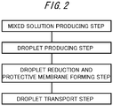
- FIG. 2 is a step diagram representing a droplet particle producing method of a first embodiment of the invention.
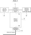
- FIG. 3 is a block diagram schematically representing a configuration of a droplet particle producing device of the first embodiment.
- the droplet particle producing method of the present embodiment includes at least the steps of producing a mixed solution by adding a compound which forms a nonvolatile membrane at the gas-liquid interface through self-aggregation to a volatile liquid (hereinafter, “mixed solution producing step”); producing a micro droplet having a diameter of 100 ⁇ m or less by spraying the mixed solution into dry air or a vacuum (hereinafter, “droplet producing step”); vaporizing the liquid in the droplet to reduce the diameter of the droplet (hereinafter, droplet reducing step); forming a membrane (protective membrane) formed of the compound at the gas-liquid interface on a surface of the droplet due to reduction in diameter of the droplet (hereinafter, “protective membrane forming step”); and transporting the droplet on which the membrane is formed to a predetermined location without making contact with other objects (hereinafter, “droplet transport step”).
- mixed solution producing step producing a micro droplet having a diameter of 100 ⁇ m or less by spraying the mixed solution into dry
- the following descriptions of the first embodiment are based on an example in which water or an aqueous solution is used as the volatile liquid, and a surfactant is used as the compound which forms a nonvolatile membrane.
- Particles (droplet) having a diameter of 100 ⁇ m or less will be occasionally referred to as micro or fine particles.
- dry air it is also possible to use, for example, oxygen, nitrogen, a noble gas, or a mixed gas of these.
- the mixed solution producing step is a preparatory step of adding a surfactant of a concentration less than the critical micelle concentration to a sample aqueous solution in preparation for the subsequent production of droplet.
- the type of surfactant (detergent) is not particularly limited, as long as it has a property to form a micelle, and the surfactant may be an ionic surfactant or a non-ionic surfactant.
- the ionic surfactant may be an anionic surfactant, a cationic surfactant, or an ampholytic surfactant.
- the surfactant is used in a small amount, it is preferable that the surfactant be an environmentally friendly surfactant that is safe to human health, taking into consideration its effects on human body and environment.
- a concentration less than a critical micelle concentration refers to a concentration low enough to allow the surfactant to exist without being adsorbed to a liquid surface (interface) or aggregating in water and forming a micelle (sphere) after being added.
- the droplet producing step is a step of spraying the aqueous solution (sample) with the added surfactant into dry air or a vacuum to produce a suspension of micro droplets of a diameter of 100 ⁇ m or less in the dry air or vacuum.
- the means of spraying the aqueous solution may be, for example, ultrasonic spraying such as that using a nebulizer, or heat evaporative spraying.
- the present embodiment preferably makes use of an atomizer capable of producing large numbers of fine micro droplets with the use of a negative pressure created by a stream of air. Such an atomizer (device) capable of efficiently producing micro droplets will be described later.
- the aerosol formed of an inverse micelle-like micro droplet (the aeromicelle described above) in which a surfactant-made protective thin membrane that prevents evaporation of the liquid is formed, is formed at the gas-liquid interface which is a surface of the liquid (droplet).
- the droplet reducing step and the protective membrane forming step are performed at the same time in parallel.
- the order, the timing, and the time of these steps are not limited.
- the droplet reducing step is a step of evaporating water or moisture in the micro droplets produced in the droplet producing step from the suspension in dry air or in a vacuum in a droplet nursing section 2 of the producing device (see FIG. 3 ) to further reduce the diameter of the micro droplets and concentrate the components of the aqueous solution.
- an aerosol having an extremely small particle size of less than 1 ⁇ m is occasionally called "aeronanomicelle".
- the protective membrane forming step is a step of forming an evaporation protecting membrane or an anti-drying membrane, which is a thin membrane formed by aligning of molecules of the added surfactant, on the surface of the micro droplet as the droplet reduces its diameter.
- concentration of the surfactant previously added to the solution is higher than the critical micelle concentration due to concentration of respective components of the aqueous solution, a single or multiple molecules of the surfactant in a manner that forms an inverse micelle-like structure are aligned on the surface of the micro droplet, and consequently, the above-mentioned thin membrane is formed.
- the volume of the droplet becomes 1/1000 of its initial volume when the particle size decreases from 10 ⁇ m to 1 ⁇ m, and accordingly, the substances (a target sample and the surfactant) dissolved in the droplet are concentrated 1000 times.
- the droplet reducing step and the protective membrane forming step are also equivalent to a concentration step of the target substance in the aqueous solution.
- the droplet particles produced are transported to a predetermined location including a place of interest a predetermined place or the like. That is, the droplet transport step is a step of transporting the micro droplet provided with the protective membrane to a predetermined location by means of, for example, a stream of gas (air), or by charging or ionizing the particles, without making contact with other objects. In this way, the droplet particles can be delivered, within its lifetime, to a place where the droplet particles are used or processed.
- long life-time refers to the time during which the droplet particle can reach the predetermined location (a place of interest) from its production, and typically means that the droplet particle remains for a time period of at least 1 second to several seconds, namely, the time period sufficiently longer than about 0.01 second to 0.5 second required for the evaporation of the moisture of the micro droplet particle, without collapsing or evaporating.
- the droplet particle producing device for producing the droplet particles at least includes spray means (aqueous solution spraying means 1) which produces a droplet having a diameter of 100 ⁇ m or less from an aqueous solution; a droplet nursing section 2 for suspending the droplet produced; and transport means 3 which transports the droplet particles produced to a predetermined location.
- spray means aqueous solution spraying means 1 which produces a droplet having a diameter of 100 ⁇ m or less from an aqueous solution
- a droplet nursing section 2 for suspending the droplet produced
- transport means 3 which transports the droplet particles produced to a predetermined location.
- aqueous solution supplying means for supplying an aqueous solution (sample) to the aqueous solution spraying means 1.
- a spray device such as an atomizer, capable of efficiently producing micro droplets having a diameter of 100 ⁇ m or less, is preferably used.
- a spray device such as an atomizer, capable of efficiently producing micro droplets having a diameter of 100 ⁇ m or less.
- a specific example of the aqueous solution spraying means 1 will be described in detail in the Examples below.
- the droplet nursing section 2 for example, an airtight tank, tank-like container capable of sealing dry air, or the like is used. At the top of the tank or container is provided an opening (hole 2a) through which the droplets sprayed by the aqueous solution spraying means 1 are introduced into the tank or container. A similar opening (hole 2b) is provided at the bottom of the tank or container as a droplet collecting section for discharging the droplet particles.
- the dry air supplied from the dry air supplying device D described later slowly travels down from the top to the bottom (from the hole 2a at the top to the hole 2b at the bottom in the figure) . That is, the droplet particles (aeromicelles) produced are transported with a stream of dry air to the droplet collecting section at the bottom of the container, without making contact with other objects and with remaining suspended in air.
- the droplet nursing section 2 may be adapted so that a vacuum, or a low-pressure environment close to a vacuum is created by drawing air or evacuating the droplet nursing section 2 through the hole 2b at the bottom.
- the transport means 3 is configured from the droplet collecting section, and a tube-like or a tubular member connected to the droplet collecting section.
- the transport means 3 is formed of an antistatic material, or is earthed (grounded) so as to prevent adsorption of the droplet particles by static electricity or the like.
- the droplet particles (aeromicelles) produced are transported from the droplet nursing section 2 to, for example, a particle counter or a mass spectrometer under the pressure of dry air.
- a particle counter or a mass spectrometer under the pressure of dry air.
- the dry air supplying device D which supplies dry air to the aqueous solution spraying means 1
- a device which at least includes a dry-air unit capable of continuously generating dry air having a relative humidity of 50% or less, and a metering pump unit such as a compressor.
- the dry air supplied from the dry air supplying device D is used as a power source or a driving source of the droplet particle producing device for micro spraying of the aqueous solution, transport of droplets, etc.
- the aqueous solution supplying device S which supplies an aqueous solution (sample) to the aqueous solution spraying means 1
- any configuration may be adopted as long as it is a device capable of supplying an aqueous solution to the spraying means 1 in measured small amounts.
- the aqueous solution supplying device S may be a combination of a microsyringe, a microsyringe pump and so on. Further, an ultrasonic spray, a heating spray or the like may be used.
- the droplet particle producing device of the present embodiment can spray droplets having a diameter of 100 ⁇ m or less and effectively and efficiently produce micro droplet particles (aeromicelles) from them.
- Example the producing device shown in FIG. 4 was used to produce droplet particles.
- the droplet particle producing device used in Example have the same basic configuration as the device described in the embodiment, and includes the aqueous solution spraying means 1, the droplet nursing section 2, the transport means 3, the dry air supplying device D, and the aqueous solution supplying device S.
- FIGS. 5A and 5B are schematic cross sectional views showing a configuration at an end (spinneret) of an aqueous solution spraying means representing the aqueous solution spraying means 1 (atomizer) used in Example.
- the end of the aqueous solution spraying means has a double tube structure in which an outer tube as a passageway of dry air is disposed on the outer side (outer diameter side) of an inner tube through which an aqueous solution flows. Accordingly, as shown in FIG.
- the aqueous solution (sample) ejected out of the inner tube is jetted into the droplet nursing section 2 in the form of micro droplets of about 5 to 20 ⁇ m formed under the negative pressure created by the high-speed outflow of dry air from the end portion of the outer tube.
- the droplet nursing section 2 of Example is a vertically narrow tank with a vertical length (height) of about 360 mm, a maximum diameter of about 42 mm ⁇ in the middle, and a volume of about 2 L. Dry air was supplied to the droplet nursing section 2 through the end of the aqueous solution spraying means 1 at a rate of about 1.5 L per hour, and was released from the bottom of the droplet nursing section 2.
- the droplet particle producing device of the foregoing configuration ( FIG. 4 , FIG. 5A ) was used to produce droplet particles.
- LAS linear sodium alkyl(dodecyl)benzenesulfonate
- the solution was then checked for the presence of droplet particles (aeronanomicelles) of a microscopic size.
- the critical micelle concentration (cmc) of LAS was 1.2 mmol/L (1200 ⁇ M).
- the LAS-containing purified water was sprayed toward the droplet nursing section 2 (the lower side of the figure) through the inner tube at a flow rate 2.0 ⁇ L/min while supplying dry air through the space between the inner tube and the outer tube of the aqueous solution spraying means 1 at a rate equivalent of 1.5 L/min.
- a measurement device light scattering particle counter KC-01E available from Rion Co., Ltd.
- FIG. 6 represents the results of the measurements of the average particle size of the droplet particles (aeromicelles) detected at LAS concentrations of 10, 20, 30, 50, and 80 ⁇ M.
- the scatter graph plots all average particle size distributions of droplets from multiple measurements.
- FIG. 7 represents changes in the average particle size taken from the measured results of FIG. 6 at each concentration.
- FIG. 7 represents expected values of size of droplet particle (aeromicelle) which will be obtained for different LAS concentrations.
- the results are in good agreement with the results of model calculations (simulations) for a monomolecular membrane in which single molecules of LAS are uniformly aligned at the interface on the surface of a droplet particle assumed to be a sphere.
- About 2800 droplets having a particle size of 0.3 to 0.5 ⁇ m, and about 120 droplets having a particle size of 0.5 to 1.0 ⁇ m were produced with 10 ⁇ M of LAS (per 2.0 ⁇ L for one minute), and about 12000 droplets having a particle size of 0.3 to 0.5 ⁇ m, and about 1100 droplets having a particle size of 0.5 to 1.0 ⁇ m were produced with 50 ⁇ M of LAS (per 2.0 ⁇ L for one minute). It is confirmed that these were detected almost continuously throughout the 1-minute measurement period. It was possible to detect the droplet particles (aeromicelles) continuously for at most 80 seconds.
- the long-life micro droplet particle of the invention is preferred for applications, for example, in directly introducing a liquid sample into a mass spectrometer and other device, and in concentrating a liquid sample on-line in such processes.
- the invention thus enables continuous monitoring of chemical substances dissolved in a liquid sample.
- the droplet particle also has other advantages, including extension of life of droplet particles used for paint sprays, and drug delivery using droplet particles as capsules.
- the invention enables efficient treatment by changing the size of droplet particles to control the reachable part of human body (nose, throat, trachea, lungs, pulmonary alveolus, etc).
Landscapes
- Chemical & Material Sciences (AREA)
- Analytical Chemistry (AREA)
- General Health & Medical Sciences (AREA)
- Life Sciences & Earth Sciences (AREA)
- Health & Medical Sciences (AREA)
- Biochemistry (AREA)
- Physics & Mathematics (AREA)
- General Physics & Mathematics (AREA)
- Immunology (AREA)
- Pathology (AREA)
- Sampling And Sample Adjustment (AREA)
- Colloid Chemistry (AREA)
- Other Investigation Or Analysis Of Materials By Electrical Means (AREA)
- Manufacturing Of Micro-Capsules (AREA)
- Medicinal Preparation (AREA)
Abstract
Description
- The present invention relates to a micro droplet particle which stably exists in the air or in a vacuum, and to a method and a device for producing such a droplet particle.
- The discharge of contaminants into groundwater from contaminated soil has become a large issue, and there is a growing interest in monitoring such contaminants. For component and concentration measurement of groundwater and sample aqueous solutions (collected samples) containing volatile contaminants such as benzene, a field sample is brought into a laboratory or facilities equipped with a large high-sensitive measurement device, and a wide range of contaminants - from heavy metals to organic compounds - including a total of 53 substances made up of 26 substances specified by environmental standards, and 27 substances which need monitoring, are measured for each different component using different analysis methods (see, for example,
Patent Literature 1 andPatent Literature 2, andPatent Literature 3 and Patent Literature 4). -
- Patent Literature 1: Japanese Unexamined Patent Publication
JP-A 2017-90306 - Patent Literature 2: Japanese Unexamined Patent Publication
JP-A 2002-48782 - Patent Literature 3: Japanese Unexamined Patent Publication
JP-A 2013-19816 - Patent Literature 4: Japanese Unexamined Patent Publication
JP-A-2016-188811 - For identification of the types and quantities (concentrations) of volatile contaminants in groundwater, there have been attempts to use a high-sensitive and high-accuracy mass spectrometer, such as an aerosol time-of-flight mass spectrometer (ATOFMS), and a multi-turn time-of-flight mass spectrometer (MULTUM), which enables an analysis of more than one component at the same time for a single introduced sample.
- However, the analysis of substances in groundwater using such a high-sensitive mass spectrometer involves problems in its preparation step. That is, when water (groundwater) which is a solvent of contaminants is finely granulated to a droplet (aerosol) having a diameter or a particle size of 100 µm or less that can be introduced into a mass spectrometer, water or moisture evaporates soon, and therefore the sample droplet disappears before it can be introduced into the device. That is, mass spectrometric measurement or identification of components in such volatile contaminants is not possible in dissolved form in an aqueous solvent such as water. In recent years, even though the mass spectrometer has achieved high sensitivity and high performance, there are many cases where measurement is difficult when a target component is a trace amount component.
- Accordingly, an object of the invention is to enable production of droplet particles which can maintain a spherical shape of a microscopic size even under dry conditions or in a vacuum.
- A droplet particle of the invention includes a volatile liquid, and a compound which forms a nonvolatile membrane at a gas-liquid interface through self-aggregation, stably existing in a gas or in a vacuum without collapsing or without evaporation of the volatile liquid inside the droplet particle.
- In addition, in the invention, it is preferably adopted that the volatile liquid is water or an alcohol, or the compound which forms a nonvolatile membrane is a surfactant.
- The droplet particle of the invention has a diameter of preferably 10 µm or less, or more preferably 1 µm or less. In the following, the droplet particle (aerosol) having a diameter of 10 µm or less will be occasionally referred to as "aeromicelle", and the droplet particle (aerosol) having a diameter of 1 µm or less will be occasionally referred to as "aeronanomicelle".
- A method for producing a droplet particle of the invention includes preparing a mixed solution in which a compound which forms a nonvolatile membrane at a gas-liquid interface through self-aggregation is dispersed in a volatile liquid, and ejecting and atomizing the mixed solution in a gas or in a vacuum to produce a droplet particle; and
forming a nonvolatile membrane at the gas-liquid interface by aligning the compound on a surface of the droplet particle having a reduced diameter due to evaporation of the volatile liquid in the gas or in the vacuum to stabilize the droplet particle. - A specific example of the method for producing a droplet particle of the invention includes the steps of:
- producing a mixed solution by adding a compound which forms a nonvolatile membrane at a gas-liquid interface through self-aggregation to a volatile liquid;
- producing a droplet having a diameter of 100 µm or less by spraying the mixed solution into dry air or a vacuum;
- vaporizing the volatile liquid in the droplet to reduce the diameter of the droplet and concentrate components of the mixed solution;
- forming a membrane formed of the compound at the gas-liquid interface on a surface of the droplet due to reduction in diameter of the droplet; and
- transporting a droplet on which the membrane is formed to a predetermined location without making contact with other objects.
- A device for producing a droplet particle of the invention includes:
- spray means which produces a droplet having a diameter of 100 µm or less from a mixed solution in which a compound which forms a nonvolatile membrane at a gas-liquid interface through self-aggregation is added to a volatile liquid;
- a droplet nursing section filled with dry air for suspending the droplet produced; and
- transport means which transports the droplet produced to a predetermined location.
- The invention provides a novel, long-life droplet particle which, despite containing a volatile liquid as a base, can stably maintain a spherical shape of a microscopic size even under dry conditions or in a vacuum.
- A method and a device for producing a droplet particle of the invention enable efficient production of the long-life droplet particle (such as aeromicelle) of a microscopic size.
- By the formation of an evaporation protecting membrane, the method and the device for producing a droplet particle of the invention can achieve advantageous effects of reducing vaporization of the dissolved substances and concentrating the substances in the droplet.
- Other objects, features, and advantages of the invention will be more clearly understood from the following descriptions and the accompanying drawings.
-
FIGS. 1A, 1B, and 1C are diagrams explaining a sequence of processes which form a droplet particle (aeromicelle) of the invention in this order; -
FIG. 2 is a step diagram explaining a droplet particle producing method of an embodiment of the invention; -
FIG. 3 is a block diagram representing a configuration of a droplet particle producing device of the embodiment; -
FIG. 4 is a diagram representing a schematic structure of a droplet particle producing device used in Example of the invention; -
FIG. 5A is a cross sectional view of an end portion of spraying means in the droplet particle producing device of Example, andFIG. 5B is an enlarged view of portion P; -
FIG. 6 is a scatter graph plotting particle sizes at different surfactant concentrations for droplet particles obtained in Example; and -
FIG. 7 is a graph plotting average particle sizes at different concentrations for droplet particles obtained in Example. - An embodiment of the invention is described below in detail, with reference to the accompanying drawings.
-
FIG. 1 is a diagram representing the process of forming a droplet particle of the present embodiment. - A droplet particle of the present embodiment is a droplet particle which includes a volatile liquid, for example, such as water and an alcohol, and a compound, such as a surfactant, which forms a nonvolatile membrane at the gas-liquid interface through self-aggregation, as illustrated in
FIG. 1C . The droplet particle stably exists in a gas or in a vacuum without collapsing, or without evaporation of the volatile liquid inside the droplet particle. - A traditional droplet particle (aerosol) containing a volatile liquid as a base and having a diameter or a particle size of 100 µm or less involves immediate evaporation of the volatile liquid (e.g., water, an alcohol) in a gas or in a vacuum, and the droplet immediately disappears.
- In the novel droplet particle of the invention, however, the compound, such as a surfactant, which forms a nonvolatile membrane at the gas-liquid interface through self-aggregation is added in an appropriate amount, and accordingly, the droplet particle stably remains for at least 1 second even in a gas or in a vacuum without collapsing, or without evaporation of the volatile liquid inside the droplet particle. This is a characteristic feature of the droplet particle of the invention.
- As used herein, the term "volatile" means that evaporation naturally takes place in a gas which has not reached a saturated vapor pressure under ordinary atmospheric pressure and room temperature conditions (15°C in this example). The term "nonvolatile", on the other hand, means that notable volume or mass reduction does not occur during handling as a result of evaporation or sublimation under ordinary atmospheric pressure and room temperature conditions. That is, water, an alcohol, and a mixture of water and an alcohol are all volatile in the invention.
- As used herein, the droplet particle being "stable" means that a surface membrane (usually, spherical in shape) formed at the gas-liquid interface remains for a long time period of at least 1 second in dry air or in a vacuum, in which drying or evaporation usually occurs. As used herein, "appropriate amount" means a concentration less than a corresponding critical micelle concentration (cmc) of a surfactant when the compound is a surfactant.
- In a method for producing the droplet particle, a mixed solution of the volatile liquid dispersing the compound, such as a surfactant, which forms a nonvolatile membrane at the gas-liquid interface through self-aggregation is first prepared. The mixed solution is then atomized by being ejected into a gas or a vacuum using a spray or an atomizer, and the droplet particle shown in
FIG. 1A is produced. - The droplet particle is then reduced in size through vaporization of the volatile liquid in the gas or vacuum, as shown in
FIG. 1B , so as to align the compound on the surface of the reduced droplet particle, and form a nonvolatile membrane (a membrane that becomes an evaporation protecting membrane) at the boundary between the droplet particle and the surrounding atmosphere (gas-liquid interface) (seeFIG. 1C ) . - In this way, the method enables stable and efficient production of droplet particles (aeromicelle) which are stable in a gas or in a vacuum. Despite being a micro droplet with a diameter or a particle size of 100 µm or less, the droplet particles can persist in a gas or in a vacuum for a long time, providing enough time for introduction into a mass spectrometer or other device.
- As mentioned above, in the present embodiment, water or an alcohol is preferably adopted as "the volatile liquid". In addition, various surfactants are preferably used as "the compound which forms a nonvolatile membrane".
- With the foregoing configuration, droplet particles, such as aeromicelles, which are stable in a gas or in a vacuum can be stably and efficiently produced.
- The following specifically describes a method and a device for producing the droplet particle.
-
FIG. 2 is a step diagram representing a droplet particle producing method of a first embodiment of the invention.FIG. 3 is a block diagram schematically representing a configuration of a droplet particle producing device of the first embodiment. - As shown in
FIG. 2 , the droplet particle producing method of the present embodiment includes at least the steps of producing a mixed solution by adding a compound which forms a nonvolatile membrane at the gas-liquid interface through self-aggregation to a volatile liquid (hereinafter, "mixed solution producing step"); producing a micro droplet having a diameter of 100 µm or less by spraying the mixed solution into dry air or a vacuum (hereinafter, "droplet producing step"); vaporizing the liquid in the droplet to reduce the diameter of the droplet (hereinafter, droplet reducing step); forming a membrane (protective membrane) formed of the compound at the gas-liquid interface on a surface of the droplet due to reduction in diameter of the droplet (hereinafter, "protective membrane forming step"); and transporting the droplet on which the membrane is formed to a predetermined location without making contact with other objects (hereinafter, "droplet transport step"). - For convenience of explanation, the following descriptions of the first embodiment are based on an example in which water or an aqueous solution is used as the volatile liquid, and a surfactant is used as the compound which forms a nonvolatile membrane. Particles (droplet) having a diameter of 100 µm or less will be occasionally referred to as micro or fine particles. Instead of dry air, it is also possible to use, for example, oxygen, nitrogen, a noble gas, or a mixed gas of these.
- To describe each step more specifically, the mixed solution producing step is a preparatory step of adding a surfactant of a concentration less than the critical micelle concentration to a sample aqueous solution in preparation for the subsequent production of droplet. The type of surfactant (detergent) is not particularly limited, as long as it has a property to form a micelle, and the surfactant may be an ionic surfactant or a non-ionic surfactant. The ionic surfactant may be an anionic surfactant, a cationic surfactant, or an ampholytic surfactant. Though the surfactant is used in a small amount, it is preferable that the surfactant be an environmentally friendly surfactant that is safe to human health, taking into consideration its effects on human body and environment.
- As used herein, a concentration less than a critical micelle concentration (cmc) refers to a concentration low enough to allow the surfactant to exist without being adsorbed to a liquid surface (interface) or aggregating in water and forming a micelle (sphere) after being added.
- The droplet producing step is a step of spraying the aqueous solution (sample) with the added surfactant into dry air or a vacuum to produce a suspension of micro droplets of a diameter of 100 µm or less in the dry air or vacuum. The means of spraying the aqueous solution may be, for example, ultrasonic spraying such as that using a nebulizer, or heat evaporative spraying. As an example, the present embodiment preferably makes use of an atomizer capable of producing large numbers of fine micro droplets with the use of a negative pressure created by a stream of air. Such an atomizer (device) capable of efficiently producing micro droplets will be described later.
- After the droplet reducing step and the protective membrane forming step described below, the aerosol formed of an inverse micelle-like micro droplet (the aeromicelle described above) in which a surfactant-made protective thin membrane that prevents evaporation of the liquid is formed, is formed at the gas-liquid interface which is a surface of the liquid (droplet). Typically, the droplet reducing step and the protective membrane forming step are performed at the same time in parallel. However, the order, the timing, and the time of these steps are not limited.
- The droplet reducing step is a step of evaporating water or moisture in the micro droplets produced in the droplet producing step from the suspension in dry air or in a vacuum in a
droplet nursing section 2 of the producing device (seeFIG. 3 ) to further reduce the diameter of the micro droplets and concentrate the components of the aqueous solution. Here, an aerosol having an extremely small particle size of less than 1 µm is occasionally called "aeronanomicelle". - The protective membrane forming step is a step of forming an evaporation protecting membrane or an anti-drying membrane, which is a thin membrane formed by aligning of molecules of the added surfactant, on the surface of the micro droplet as the droplet reduces its diameter. Here, when the concentration of the surfactant previously added to the solution is higher than the critical micelle concentration due to concentration of respective components of the aqueous solution, a single or multiple molecules of the surfactant in a manner that forms an inverse micelle-like structure are aligned on the surface of the micro droplet, and consequently, the above-mentioned thin membrane is formed.
- Here, for example, the volume of the droplet becomes 1/1000 of its initial volume when the particle size decreases from 10 µm to 1 µm, and accordingly, the substances (a target sample and the surfactant) dissolved in the droplet are concentrated 1000 times. In this way, the droplet reducing step and the protective membrane forming step are also equivalent to a concentration step of the target substance in the aqueous solution.
- With the foregoing configuration, long-life droplet particles, suspended in air or in a vacuum, can be stably produced in the droplet nursing section 2 (see
FIG. 3 ). - In the transport step, the droplet particles produced are transported to a predetermined location including a place of interest a predetermined place or the like. That is, the droplet transport step is a step of transporting the micro droplet provided with the protective membrane to a predetermined location by means of, for example, a stream of gas (air), or by charging or ionizing the particles, without making contact with other objects. In this way, the droplet particles can be delivered, within its lifetime, to a place where the droplet particles are used or processed.
- As used herein, "long life-time" or "long-life" refers to the time during which the droplet particle can reach the predetermined location (a place of interest) from its production, and typically means that the droplet particle remains for a time period of at least 1 second to several seconds, namely, the time period sufficiently longer than about 0.01 second to 0.5 second required for the evaporation of the moisture of the micro droplet particle, without collapsing or evaporating.
- As shown in the block diagram of
FIG. 3 , the droplet particle producing device for producing the droplet particles (aeromicelles) at least includes spray means (aqueous solution spraying means 1) which produces a droplet having a diameter of 100 µm or less from an aqueous solution; adroplet nursing section 2 for suspending the droplet produced; and transport means 3 which transports the droplet particles produced to a predetermined location. In addition to these means and sections, the droplet particle producing device of the present embodiment (FIG. 3 ) includes dry air supplying means (device D) for supplying dry air to the aqueous solution spraying means 1; and aqueous solution supplying means (device S) for supplying an aqueous solution (sample) to the aqueous solution spraying means 1. - As mentioned above, as the aqueous solution spraying means 1, a spray device, such as an atomizer, capable of efficiently producing micro droplets having a diameter of 100 µm or less, is preferably used. A specific example of the aqueous solution spraying means 1 will be described in detail in the Examples below.
- As the
droplet nursing section 2, for example, an airtight tank, tank-like container capable of sealing dry air, or the like is used. At the top of the tank or container is provided an opening (hole 2a) through which the droplets sprayed by the aqueous solution spraying means 1 are introduced into the tank or container. A similar opening (hole 2b) is provided at the bottom of the tank or container as a droplet collecting section for discharging the droplet particles. - Inside the
droplet nursing section 2, the dry air supplied from the dry air supplying device D described later slowly travels down from the top to the bottom (from thehole 2a at the top to thehole 2b at the bottom in the figure) . That is, the droplet particles (aeromicelles) produced are transported with a stream of dry air to the droplet collecting section at the bottom of the container, without making contact with other objects and with remaining suspended in air. - The
droplet nursing section 2 may be adapted so that a vacuum, or a low-pressure environment close to a vacuum is created by drawing air or evacuating thedroplet nursing section 2 through thehole 2b at the bottom. - The transport means 3 is configured from the droplet collecting section, and a tube-like or a tubular member connected to the droplet collecting section. The transport means 3 is formed of an antistatic material, or is earthed (grounded) so as to prevent adsorption of the droplet particles by static electricity or the like.
- In the present embodiment, the droplet particles (aeromicelles) produced are transported from the
droplet nursing section 2 to, for example, a particle counter or a mass spectrometer under the pressure of dry air. However, in the case of a device devoid of such a pressure source or a positive pressure source, it is possible to additionally provide a negative pressure source or the like for drawing the droplet particles from thedroplet nursing section 2 to a predetermined location such as a mass spectrometer. - As the dry air supplying device D which supplies dry air to the aqueous solution spraying means 1, a device is used which at least includes a dry-air unit capable of continuously generating dry air having a relative humidity of 50% or less, and a metering pump unit such as a compressor. The dry air supplied from the dry air supplying device D is used as a power source or a driving source of the droplet particle producing device for micro spraying of the aqueous solution, transport of droplets, etc.
- As the aqueous solution supplying device S which supplies an aqueous solution (sample) to the aqueous solution spraying means 1, any configuration may be adopted as long as it is a device capable of supplying an aqueous solution to the spraying means 1 in measured small amounts. For example, the aqueous solution supplying device S may be a combination of a microsyringe, a microsyringe pump and so on. Further, an ultrasonic spray, a heating spray or the like may be used.
- With the foregoing configuration, the droplet particle producing device of the present embodiment can spray droplets having a diameter of 100 µm or less and effectively and efficiently produce micro droplet particles (aeromicelles) from them.
- The following describes Example of actual production of droplet particles.
- In Example, the producing device shown in
FIG. 4 was used to produce droplet particles. The droplet particle producing device used in Example have the same basic configuration as the device described in the embodiment, and includes the aqueous solution spraying means 1, thedroplet nursing section 2, the transport means 3, the dry air supplying device D, and the aqueous solution supplying device S. -
FIGS. 5A and 5B are schematic cross sectional views showing a configuration at an end (spinneret) of an aqueous solution spraying means representing the aqueous solution spraying means 1 (atomizer) used in Example. The end of the aqueous solution spraying means has a double tube structure in which an outer tube as a passageway of dry air is disposed on the outer side (outer diameter side) of an inner tube through which an aqueous solution flows. Accordingly, as shown inFIG. 5B , the aqueous solution (sample) ejected out of the inner tube is jetted into thedroplet nursing section 2 in the form of micro droplets of about 5 to 20 µm formed under the negative pressure created by the high-speed outflow of dry air from the end portion of the outer tube. - The
droplet nursing section 2 of Example is a vertically narrow tank with a vertical length (height) of about 360 mm, a maximum diameter of about 42 mmφ in the middle, and a volume of about 2 L. Dry air was supplied to thedroplet nursing section 2 through the end of the aqueous solution spraying means 1 at a rate of about 1.5 L per hour, and was released from the bottom of thedroplet nursing section 2. - The droplet particle producing device of the foregoing configuration (
FIG. 4 ,FIG. 5A ) was used to produce droplet particles. Purified water was used as the aqueous solution (water), and 10 to 100 µM (M = mol/L) of a linear sodium alkyl(dodecyl)benzenesulfonate (hereinafter, simply "LAS"), which was a typical anionic surfactant, was added thereto. The solution was then checked for the presence of droplet particles (aeronanomicelles) of a microscopic size. The critical micelle concentration (cmc) of LAS was 1.2 mmol/L (1200 µM). - As shown in
FIG. 5 B , the LAS-containing purified water was sprayed toward the droplet nursing section 2 (the lower side of the figure) through the inner tube at a flow rate 2.0 µL/min while supplying dry air through the space between the inner tube and the outer tube of the aqueous solution spraying means 1 at a rate equivalent of 1.5 L/min. With a measurement device (light scattering particle counter KC-01E available from Rion Co., Ltd.) directly attached to the solution collecting section disposed at the bottom of thedroplet nursing section 2, a number and a particle size distribution of droplet particles (aeromicelles) which reach the bottom of thedroplet nursing section 2 was measured for one minute per experiment. It is to be noted here that only a few droplet particles will be observed in a test conducted with purified water containing no LAS. -
FIG. 6 represents the results of the measurements of the average particle size of the droplet particles (aeromicelles) detected at LAS concentrations of 10, 20, 30, 50, and 80 µM. The scatter graph plots all average particle size distributions of droplets from multiple measurements. - Next, the graph shown in
FIG. 7 represents changes in the average particle size taken from the measured results ofFIG. 6 at each concentration. In other words,FIG. 7 represents expected values of size of droplet particle (aeromicelle) which will be obtained for different LAS concentrations. The results are in good agreement with the results of model calculations (simulations) for a monomolecular membrane in which single molecules of LAS are uniformly aligned at the interface on the surface of a droplet particle assumed to be a sphere. - About 2800 droplets having a particle size of 0.3 to 0.5 µm, and about 120 droplets having a particle size of 0.5 to 1.0 µm were produced with 10 µM of LAS (per 2.0 µL for one minute), and about 12000 droplets having a particle size of 0.3 to 0.5 µm, and about 1100 droplets having a particle size of 0.5 to 1.0 µm were produced with 50 µM of LAS (per 2.0 µL for one minute). It is confirmed that these were detected almost continuously throughout the 1-minute measurement period. It was possible to detect the droplet particles (aeromicelles) continuously for at most 80 seconds.
- It has been found that the method using the producing device of the invention could stably and efficiently produce droplet particles (aeromicelles or aeronanomicelles) of a microscopic size from water containing LAS.
- It is confirmed that similar results to the above Example were obtained even when sodium dodecyl sulfate (SDS; a critical micelle concentration (cmc) of 8.2 mM) was used as the surfactant added.
- The invention may be embodied in other specific forms without departing from the spirit or essential characteristics thereof. The present embodiments are therefore to be considered in all respects as illustrative and not restrictive, the scope of the invention being indicated by the appended claims rather than by the foregoing description and all changes which come within the meaning and the range of equivalency of the claims are therefore intended to be embraced therein.
- The long-life micro droplet particle of the invention is preferred for applications, for example, in directly introducing a liquid sample into a mass spectrometer and other device, and in concentrating a liquid sample on-line in such processes. The invention thus enables continuous monitoring of chemical substances dissolved in a liquid sample. The droplet particle also has other advantages, including extension of life of droplet particles used for paint sprays, and drug delivery using droplet particles as capsules. For drug delivery in particular, the invention enables efficient treatment by changing the size of droplet particles to control the reachable part of human body (nose, throat, trachea, lungs, pulmonary alveolus, etc).
-
- 1:
- Aqueous solution spraying means
- 2:
- Droplet nursing section
- 3:
- Transport means
- D:
- Dry air supplying device
- S:
- Aqueous solution supplying device
Claims (8)
- A droplet particle, comprising:a volatile liquid; anda compound which forms a nonvolatile membrane at a gas-liquid interface through self-aggregation,stably existing in a gas or in a vacuum without collapsing or without evaporation of the volatile liquid inside the droplet particle.
- The droplet particle according to claim 1, wherein the volatile liquid is water or an alcohol.
- The droplet particle according to claim 1 or 2, wherein the compound which forms a nonvolatile membrane is a surfactant.
- The droplet particle according to any one of claims 1 to 3, wherein the droplet particle has a diameter of 10 µm or less.
- The droplet particle according to any one of claims 1 to 4, wherein the droplet particle has a diameter of 1 µm or less.
- A method for producing a droplet particle, comprising:preparing a mixed solution in which a compound which forms a nonvolatile membrane at a gas-liquid interface through self-aggregation is dispersed in a volatile liquid, and ejecting and atomizing the mixed solution in a gas or in a vacuum to produce a droplet particle; andforming a nonvolatile membrane at the gas-liquid interface by aligning the compound on a surface of the droplet particle having a reduced diameter due to evaporation of the volatile liquid in the gas or in the vacuum to stabilize the droplet particle.
- A method for producing a droplet particle, comprising the steps of:producing a mixed solution by adding a compound which forms a nonvolatile membrane at a gas-liquid interface through self-aggregation to a volatile liquid;producing a droplet having a diameter of 100 µm or less by spraying the mixed solution into dry air or a vacuum;vaporizing the volatile liquid in the droplet to reduce the diameter of the droplet;forming a membrane formed of the compound at the gas-liquid interface on a surface of the droplet due to reduction in diameter of the droplet; andtransporting the droplet on which the membrane is formed to a predetermined location without making contact with other objects.
- A device for producing a droplet particle, comprising:spray means which produces a droplet having a diameter of 100 µm or less from a mixed solution in which a compound which forms a nonvolatile membrane at a gas-liquid interface through self-aggregation is added to a volatile liquid;a droplet nursing section filled with dry air for suspending the droplet produced; andtransport means which transports the droplet produced to a predetermined location.
Applications Claiming Priority (2)
| Application Number | Priority Date | Filing Date | Title |
|---|---|---|---|
| JP2018020497 | 2018-02-07 | ||
| PCT/JP2018/029989 WO2019155662A1 (en) | 2018-02-07 | 2018-08-09 | Droplet particles, and method and device for generating droplet particles |
Publications (3)
| Publication Number | Publication Date |
|---|---|
| EP3550279A1 true EP3550279A1 (en) | 2019-10-09 |
| EP3550279A4 EP3550279A4 (en) | 2020-02-26 |
| EP3550279B1 EP3550279B1 (en) | 2023-05-10 |
Family
ID=67436875
Family Applications (1)
| Application Number | Title | Priority Date | Filing Date |
|---|---|---|---|
| EP18786201.6A Active EP3550279B1 (en) | 2018-02-07 | 2018-08-09 | Method for generating droplet particles |
Country Status (4)
| Country | Link |
|---|---|
| US (1) | US12025544B2 (en) |
| EP (1) | EP3550279B1 (en) |
| JP (2) | JP6806795B2 (en) |
| WO (1) | WO2019155662A1 (en) |
Families Citing this family (3)
| Publication number | Priority date | Publication date | Assignee | Title |
|---|---|---|---|---|
| CN112473500B (en) * | 2020-11-24 | 2022-03-29 | 华中科技大学 | High flux liquid drop array rapid preparation device based on spray assistance |
| US20220212959A1 (en) * | 2021-01-06 | 2022-07-07 | The Government Of The United States Of America, As Represented By The Secretary Of The Navy | Plasma aerosol hybrid method for fluoro compound abatement |
| GB2608365B (en) * | 2021-06-25 | 2024-11-27 | Thermo Fisher Scient Bremen Gmbh | Improvements relating toTime-of-Flight mass analysers |
Family Cites Families (10)
| Publication number | Priority date | Publication date | Assignee | Title |
|---|---|---|---|---|
| JP2776315B2 (en) | 1995-08-29 | 1998-07-16 | 株式会社日立製作所 | Capillary pipe cleaning method |
| US20020001544A1 (en) | 1997-08-28 | 2002-01-03 | Robert Hess | System and method for high throughput processing of droplets |
| JP3772692B2 (en) | 2000-05-26 | 2006-05-10 | 株式会社島津製作所 | Analytical aqueous solution metering / feeding mechanism and water quality analyzer using the same |
| FR2929266B1 (en) * | 2008-03-31 | 2010-03-19 | Inst Francais Du Petrole | MESOSTRUCTURE MATERIAL WITH A HIGH ALUMINUM CONTENT AND CONSISTING OF SPHERICAL PARTICLES OF A SPECIFIC SIZE |
| GB201011019D0 (en) | 2010-07-01 | 2010-08-18 | Weston Richard | Ionisation mass spectrometry |
| JP5807872B2 (en) | 2011-07-12 | 2015-11-10 | 国立研究開発法人産業技術総合研究所 | Method for estimating the amount of natural heavy metal elements dissolved in water |
| US20150275126A1 (en) * | 2012-09-24 | 2015-10-01 | Exxonmobil Research And Engineering Company | Inverse micellar compositions containing lubricant additives |
| WO2014194272A2 (en) | 2013-05-31 | 2014-12-04 | University Of Washington Through Its Center For Commercialization | Droplet-mass spectrometer interface |
| JP6481201B2 (en) | 2015-03-30 | 2019-03-13 | 新日鐵住金株式会社 | Method for measuring the concentration of specified chemical substances or specified wastewater |
| JP6601765B2 (en) | 2015-11-12 | 2019-11-06 | 清水建設株式会社 | Groundwater sampling apparatus, sampling probe, and groundwater sampling method |
-
2018
- 2018-08-09 EP EP18786201.6A patent/EP3550279B1/en active Active
- 2018-08-09 US US16/096,096 patent/US12025544B2/en active Active
- 2018-08-09 JP JP2018557147A patent/JP6806795B2/en active Active
- 2018-08-09 WO PCT/JP2018/029989 patent/WO2019155662A1/en not_active Ceased
-
2020
- 2020-06-29 JP JP2020111474A patent/JP7228166B2/en active Active
Also Published As
| Publication number | Publication date |
|---|---|
| JP6806795B2 (en) | 2021-01-06 |
| EP3550279B1 (en) | 2023-05-10 |
| JP2020173263A (en) | 2020-10-22 |
| EP3550279A4 (en) | 2020-02-26 |
| WO2019155662A1 (en) | 2019-08-15 |
| JP7228166B2 (en) | 2023-02-24 |
| JPWO2019155662A1 (en) | 2020-02-27 |
| US20210223147A1 (en) | 2021-07-22 |
| US12025544B2 (en) | 2024-07-02 |
Similar Documents
| Publication | Publication Date | Title |
|---|---|---|
| US5873523A (en) | Electrospray employing corona-assisted cone-jet mode | |
| EP3550279B1 (en) | Method for generating droplet particles | |
| EP1081487B1 (en) | Nebulizer | |
| Chen et al. | Characteristics of probe electrospray generated from a solid needle | |
| US12340998B2 (en) | Condensed liquid aerosol particle spray (CLAPS)—a novel on-line liquid aerosol sampling and ionization technique | |
| CN102574058B (en) | For the system of anti-backflow in ion gun | |
| US20030093228A1 (en) | Method of analyzing particles suspended in liquid and liquid-suspended particle analyzer for carrying out the method | |
| Wingen et al. | Probing surfaces of atmospherically relevant organic particles by easy ambient sonic-spray ionization mass spectrometry (EASI-MS) | |
| US8421006B2 (en) | System and method for generating sprays using electrical fields | |
| WO2015074959A1 (en) | Atomizer system | |
| CN111540665A (en) | Ionization device and application thereof | |
| US9768005B1 (en) | Electrospray ionizer for mass spectrometry of aerosol particles | |
| Mühlig et al. | Nanometre-sized droplets from a gas dynamic virtual nozzle | |
| US8671874B2 (en) | Process and apparatus for localized coating of assembled cascade impactor particle collection surfaces | |
| CN121100266A (en) | Characterization of aerosol particles using decomposition induced by pneumatic atomizers | |
| Jennerjohn et al. | Design, demonstration and performance of a versatile electrospray aerosol generator for nanomaterial research and applications | |
| Parisi et al. | Application of electrohydrodynamic atomisation to surface disinfection | |
| US20100230586A1 (en) | Method and apparatus for providing a sample for a subsequent analysis | |
| Mikuška | Generator of fine polydisperse aerosol | |
| Xue et al. | Characterization of Coagulation and Charge Status of Particles Generated by a Bipolar Electrospray (BiES) | |
| RU2608362C2 (en) | Device of stable electro-spraying solutions of substances at atmospheric pressure for ion sources | |
| Pervukhin et al. | A Collison nebulizer as an ion source for mass spectrometry analysis | |
| Pervukhin et al. | Collison nebulizer as a new soft ionization source for mass spectrometry | |
| TWI777180B (en) | Adjustable system for calibrating component concentration of aerosol | |
| JP4789533B2 (en) | Information acquisition method and information acquisition apparatus |
Legal Events
| Date | Code | Title | Description |
|---|---|---|---|
| STAA | Information on the status of an ep patent application or granted ep patent |
Free format text: STATUS: UNKNOWN |
|
| STAA | Information on the status of an ep patent application or granted ep patent |
Free format text: STATUS: THE INTERNATIONAL PUBLICATION HAS BEEN MADE |
|
| PUAI | Public reference made under article 153(3) epc to a published international application that has entered the european phase |
Free format text: ORIGINAL CODE: 0009012 |
|
| STAA | Information on the status of an ep patent application or granted ep patent |
Free format text: STATUS: REQUEST FOR EXAMINATION WAS MADE |
|
| 17P | Request for examination filed |
Effective date: 20181025 |
|
| AK | Designated contracting states |
Kind code of ref document: A1 Designated state(s): AL AT BE BG CH CY CZ DE DK EE ES FI FR GB GR HR HU IE IS IT LI LT LU LV MC MK MT NL NO PL PT RO RS SE SI SK SM TR |
|
| AX | Request for extension of the european patent |
Extension state: BA ME |
|
| A4 | Supplementary search report drawn up and despatched |
Effective date: 20200129 |
|
| RIC1 | Information provided on ipc code assigned before grant |
Ipc: H01J 49/04 20060101ALN20200123BHEP Ipc: G01N 30/84 20060101ALN20200123BHEP Ipc: G01N 1/40 20060101AFI20200123BHEP |
|
| STAA | Information on the status of an ep patent application or granted ep patent |
Free format text: STATUS: EXAMINATION IS IN PROGRESS |
|
| 17Q | First examination report despatched |
Effective date: 20201204 |
|
| DAV | Request for validation of the european patent (deleted) | ||
| DAX | Request for extension of the european patent (deleted) | ||
| REG | Reference to a national code |
Ref country code: DE Ref legal event code: R079 Ref document number: 602018049683 Country of ref document: DE Free format text: PREVIOUS MAIN CLASS: G01N0001280000 Ipc: G01N0001400000 |
|
| GRAP | Despatch of communication of intention to grant a patent |
Free format text: ORIGINAL CODE: EPIDOSNIGR1 |
|
| STAA | Information on the status of an ep patent application or granted ep patent |
Free format text: STATUS: GRANT OF PATENT IS INTENDED |
|
| RIC1 | Information provided on ipc code assigned before grant |
Ipc: G01N 30/84 20060101ALN20221018BHEP Ipc: H01J 49/04 20060101ALN20221018BHEP Ipc: G01N 1/40 20060101AFI20221018BHEP |
|
| RIC1 | Information provided on ipc code assigned before grant |
Ipc: G01N 30/84 20060101ALN20221031BHEP Ipc: H01J 49/04 20060101ALN20221031BHEP Ipc: G01N 1/40 20060101AFI20221031BHEP |
|
| RIC1 | Information provided on ipc code assigned before grant |
Ipc: G01N 30/84 20060101ALN20221107BHEP Ipc: H01J 49/04 20060101ALN20221107BHEP Ipc: G01N 1/40 20060101AFI20221107BHEP |
|
| INTG | Intention to grant announced |
Effective date: 20221123 |
|
| GRAS | Grant fee paid |
Free format text: ORIGINAL CODE: EPIDOSNIGR3 |
|
| GRAA | (expected) grant |
Free format text: ORIGINAL CODE: 0009210 |
|
| STAA | Information on the status of an ep patent application or granted ep patent |
Free format text: STATUS: THE PATENT HAS BEEN GRANTED |
|
| AK | Designated contracting states |
Kind code of ref document: B1 Designated state(s): AL AT BE BG CH CY CZ DE DK EE ES FI FR GB GR HR HU IE IS IT LI LT LU LV MC MK MT NL NO PL PT RO RS SE SI SK SM TR |
|
| REG | Reference to a national code |
Ref country code: GB Ref legal event code: FG4D |
|
| REG | Reference to a national code |
Ref country code: AT Ref legal event code: REF Ref document number: 1567140 Country of ref document: AT Kind code of ref document: T Effective date: 20230515 Ref country code: CH Ref legal event code: EP |
|
| REG | Reference to a national code |
Ref country code: DE Ref legal event code: R096 Ref document number: 602018049683 Country of ref document: DE |
|
| REG | Reference to a national code |
Ref country code: IE Ref legal event code: FG4D |
|
| P01 | Opt-out of the competence of the unified patent court (upc) registered |
Effective date: 20230509 |
|
| REG | Reference to a national code |
Ref country code: LT Ref legal event code: MG9D |
|
| REG | Reference to a national code |
Ref country code: NL Ref legal event code: MP Effective date: 20230510 |
|
| REG | Reference to a national code |
Ref country code: AT Ref legal event code: MK05 Ref document number: 1567140 Country of ref document: AT Kind code of ref document: T Effective date: 20230510 |
|
| PG25 | Lapsed in a contracting state [announced via postgrant information from national office to epo] |
Ref country code: SE Free format text: LAPSE BECAUSE OF FAILURE TO SUBMIT A TRANSLATION OF THE DESCRIPTION OR TO PAY THE FEE WITHIN THE PRESCRIBED TIME-LIMIT Effective date: 20230510 Ref country code: PT Free format text: LAPSE BECAUSE OF FAILURE TO SUBMIT A TRANSLATION OF THE DESCRIPTION OR TO PAY THE FEE WITHIN THE PRESCRIBED TIME-LIMIT Effective date: 20230911 Ref country code: NO Free format text: LAPSE BECAUSE OF FAILURE TO SUBMIT A TRANSLATION OF THE DESCRIPTION OR TO PAY THE FEE WITHIN THE PRESCRIBED TIME-LIMIT Effective date: 20230810 Ref country code: NL Free format text: LAPSE BECAUSE OF FAILURE TO SUBMIT A TRANSLATION OF THE DESCRIPTION OR TO PAY THE FEE WITHIN THE PRESCRIBED TIME-LIMIT Effective date: 20230510 Ref country code: ES Free format text: LAPSE BECAUSE OF FAILURE TO SUBMIT A TRANSLATION OF THE DESCRIPTION OR TO PAY THE FEE WITHIN THE PRESCRIBED TIME-LIMIT Effective date: 20230510 Ref country code: AT Free format text: LAPSE BECAUSE OF FAILURE TO SUBMIT A TRANSLATION OF THE DESCRIPTION OR TO PAY THE FEE WITHIN THE PRESCRIBED TIME-LIMIT Effective date: 20230510 |
|
| PG25 | Lapsed in a contracting state [announced via postgrant information from national office to epo] |
Ref country code: RS Free format text: LAPSE BECAUSE OF FAILURE TO SUBMIT A TRANSLATION OF THE DESCRIPTION OR TO PAY THE FEE WITHIN THE PRESCRIBED TIME-LIMIT Effective date: 20230510 Ref country code: PL Free format text: LAPSE BECAUSE OF FAILURE TO SUBMIT A TRANSLATION OF THE DESCRIPTION OR TO PAY THE FEE WITHIN THE PRESCRIBED TIME-LIMIT Effective date: 20230510 Ref country code: LV Free format text: LAPSE BECAUSE OF FAILURE TO SUBMIT A TRANSLATION OF THE DESCRIPTION OR TO PAY THE FEE WITHIN THE PRESCRIBED TIME-LIMIT Effective date: 20230510 Ref country code: LT Free format text: LAPSE BECAUSE OF FAILURE TO SUBMIT A TRANSLATION OF THE DESCRIPTION OR TO PAY THE FEE WITHIN THE PRESCRIBED TIME-LIMIT Effective date: 20230510 Ref country code: IS Free format text: LAPSE BECAUSE OF FAILURE TO SUBMIT A TRANSLATION OF THE DESCRIPTION OR TO PAY THE FEE WITHIN THE PRESCRIBED TIME-LIMIT Effective date: 20230910 Ref country code: HR Free format text: LAPSE BECAUSE OF FAILURE TO SUBMIT A TRANSLATION OF THE DESCRIPTION OR TO PAY THE FEE WITHIN THE PRESCRIBED TIME-LIMIT Effective date: 20230510 Ref country code: GR Free format text: LAPSE BECAUSE OF FAILURE TO SUBMIT A TRANSLATION OF THE DESCRIPTION OR TO PAY THE FEE WITHIN THE PRESCRIBED TIME-LIMIT Effective date: 20230811 |
|
| PG25 | Lapsed in a contracting state [announced via postgrant information from national office to epo] |
Ref country code: FI Free format text: LAPSE BECAUSE OF FAILURE TO SUBMIT A TRANSLATION OF THE DESCRIPTION OR TO PAY THE FEE WITHIN THE PRESCRIBED TIME-LIMIT Effective date: 20230510 |
|
| PG25 | Lapsed in a contracting state [announced via postgrant information from national office to epo] |
Ref country code: SK Free format text: LAPSE BECAUSE OF FAILURE TO SUBMIT A TRANSLATION OF THE DESCRIPTION OR TO PAY THE FEE WITHIN THE PRESCRIBED TIME-LIMIT Effective date: 20230510 |
|
| PG25 | Lapsed in a contracting state [announced via postgrant information from national office to epo] |
Ref country code: SM Free format text: LAPSE BECAUSE OF FAILURE TO SUBMIT A TRANSLATION OF THE DESCRIPTION OR TO PAY THE FEE WITHIN THE PRESCRIBED TIME-LIMIT Effective date: 20230510 Ref country code: SK Free format text: LAPSE BECAUSE OF FAILURE TO SUBMIT A TRANSLATION OF THE DESCRIPTION OR TO PAY THE FEE WITHIN THE PRESCRIBED TIME-LIMIT Effective date: 20230510 Ref country code: RO Free format text: LAPSE BECAUSE OF FAILURE TO SUBMIT A TRANSLATION OF THE DESCRIPTION OR TO PAY THE FEE WITHIN THE PRESCRIBED TIME-LIMIT Effective date: 20230510 Ref country code: EE Free format text: LAPSE BECAUSE OF FAILURE TO SUBMIT A TRANSLATION OF THE DESCRIPTION OR TO PAY THE FEE WITHIN THE PRESCRIBED TIME-LIMIT Effective date: 20230510 Ref country code: DK Free format text: LAPSE BECAUSE OF FAILURE TO SUBMIT A TRANSLATION OF THE DESCRIPTION OR TO PAY THE FEE WITHIN THE PRESCRIBED TIME-LIMIT Effective date: 20230510 Ref country code: CZ Free format text: LAPSE BECAUSE OF FAILURE TO SUBMIT A TRANSLATION OF THE DESCRIPTION OR TO PAY THE FEE WITHIN THE PRESCRIBED TIME-LIMIT Effective date: 20230510 |
|
| REG | Reference to a national code |
Ref country code: DE Ref legal event code: R097 Ref document number: 602018049683 Country of ref document: DE |
|
| PG25 | Lapsed in a contracting state [announced via postgrant information from national office to epo] |
Ref country code: MC Free format text: LAPSE BECAUSE OF FAILURE TO SUBMIT A TRANSLATION OF THE DESCRIPTION OR TO PAY THE FEE WITHIN THE PRESCRIBED TIME-LIMIT Effective date: 20230510 |
|
| PLBE | No opposition filed within time limit |
Free format text: ORIGINAL CODE: 0009261 |
|
| STAA | Information on the status of an ep patent application or granted ep patent |
Free format text: STATUS: NO OPPOSITION FILED WITHIN TIME LIMIT |
|
| REG | Reference to a national code |
Ref country code: CH Ref legal event code: PL |
|
| PG25 | Lapsed in a contracting state [announced via postgrant information from national office to epo] |
Ref country code: MC Free format text: LAPSE BECAUSE OF FAILURE TO SUBMIT A TRANSLATION OF THE DESCRIPTION OR TO PAY THE FEE WITHIN THE PRESCRIBED TIME-LIMIT Effective date: 20230510 |
|
| PG25 | Lapsed in a contracting state [announced via postgrant information from national office to epo] |
Ref country code: LU Free format text: LAPSE BECAUSE OF NON-PAYMENT OF DUE FEES Effective date: 20230809 |
|
| 26N | No opposition filed |
Effective date: 20240213 |
|
| PG25 | Lapsed in a contracting state [announced via postgrant information from national office to epo] |
Ref country code: LU Free format text: LAPSE BECAUSE OF NON-PAYMENT OF DUE FEES Effective date: 20230809 Ref country code: CH Free format text: LAPSE BECAUSE OF NON-PAYMENT OF DUE FEES Effective date: 20230831 |
|
| PG25 | Lapsed in a contracting state [announced via postgrant information from national office to epo] |
Ref country code: SI Free format text: LAPSE BECAUSE OF FAILURE TO SUBMIT A TRANSLATION OF THE DESCRIPTION OR TO PAY THE FEE WITHIN THE PRESCRIBED TIME-LIMIT Effective date: 20230510 |
|
| REG | Reference to a national code |
Ref country code: BE Ref legal event code: MM Effective date: 20230831 |
|
| REG | Reference to a national code |
Ref country code: IE Ref legal event code: MM4A |
|
| PG25 | Lapsed in a contracting state [announced via postgrant information from national office to epo] |
Ref country code: SI Free format text: LAPSE BECAUSE OF FAILURE TO SUBMIT A TRANSLATION OF THE DESCRIPTION OR TO PAY THE FEE WITHIN THE PRESCRIBED TIME-LIMIT Effective date: 20230510 Ref country code: IT Free format text: LAPSE BECAUSE OF FAILURE TO SUBMIT A TRANSLATION OF THE DESCRIPTION OR TO PAY THE FEE WITHIN THE PRESCRIBED TIME-LIMIT Effective date: 20230510 |
|
| PG25 | Lapsed in a contracting state [announced via postgrant information from national office to epo] |
Ref country code: IE Free format text: LAPSE BECAUSE OF NON-PAYMENT OF DUE FEES Effective date: 20230809 |
|
| PG25 | Lapsed in a contracting state [announced via postgrant information from national office to epo] |
Ref country code: IE Free format text: LAPSE BECAUSE OF NON-PAYMENT OF DUE FEES Effective date: 20230809 |
|
| PG25 | Lapsed in a contracting state [announced via postgrant information from national office to epo] |
Ref country code: BE Free format text: LAPSE BECAUSE OF NON-PAYMENT OF DUE FEES Effective date: 20230831 |
|
| PG25 | Lapsed in a contracting state [announced via postgrant information from national office to epo] |
Ref country code: BG Free format text: LAPSE BECAUSE OF FAILURE TO SUBMIT A TRANSLATION OF THE DESCRIPTION OR TO PAY THE FEE WITHIN THE PRESCRIBED TIME-LIMIT Effective date: 20230510 |
|
| PG25 | Lapsed in a contracting state [announced via postgrant information from national office to epo] |
Ref country code: BG Free format text: LAPSE BECAUSE OF FAILURE TO SUBMIT A TRANSLATION OF THE DESCRIPTION OR TO PAY THE FEE WITHIN THE PRESCRIBED TIME-LIMIT Effective date: 20230510 |
|
| PG25 | Lapsed in a contracting state [announced via postgrant information from national office to epo] |
Ref country code: CY Free format text: LAPSE BECAUSE OF FAILURE TO SUBMIT A TRANSLATION OF THE DESCRIPTION OR TO PAY THE FEE WITHIN THE PRESCRIBED TIME-LIMIT; INVALID AB INITIO Effective date: 20180809 |
|
| PG25 | Lapsed in a contracting state [announced via postgrant information from national office to epo] |
Ref country code: HU Free format text: LAPSE BECAUSE OF FAILURE TO SUBMIT A TRANSLATION OF THE DESCRIPTION OR TO PAY THE FEE WITHIN THE PRESCRIBED TIME-LIMIT; INVALID AB INITIO Effective date: 20180809 |
|
| PGFP | Annual fee paid to national office [announced via postgrant information from national office to epo] |
Ref country code: GB Payment date: 20250812 Year of fee payment: 8 |
|
| PGFP | Annual fee paid to national office [announced via postgrant information from national office to epo] |
Ref country code: FR Payment date: 20250821 Year of fee payment: 8 |
|
| PG25 | Lapsed in a contracting state [announced via postgrant information from national office to epo] |
Ref country code: TR Free format text: LAPSE BECAUSE OF FAILURE TO SUBMIT A TRANSLATION OF THE DESCRIPTION OR TO PAY THE FEE WITHIN THE PRESCRIBED TIME-LIMIT Effective date: 20230510 |
|
| PGFP | Annual fee paid to national office [announced via postgrant information from national office to epo] |
Ref country code: DE Payment date: 20251021 Year of fee payment: 8 |