EP3550082B1 - Cab for work vehicle and work vehicle - Google Patents
Cab for work vehicle and work vehicle Download PDFInfo
- Publication number
- EP3550082B1 EP3550082B1 EP18823718.4A EP18823718A EP3550082B1 EP 3550082 B1 EP3550082 B1 EP 3550082B1 EP 18823718 A EP18823718 A EP 18823718A EP 3550082 B1 EP3550082 B1 EP 3550082B1
- Authority
- EP
- European Patent Office
- Prior art keywords
- cab
- work vehicle
- operator seat
- window
- console
- Prior art date
- Legal status (The legal status is an assumption and is not a legal conclusion. Google has not performed a legal analysis and makes no representation as to the accuracy of the status listed.)
- Active
Links
Images



Classifications
-
- E—FIXED CONSTRUCTIONS
- E02—HYDRAULIC ENGINEERING; FOUNDATIONS; SOIL SHIFTING
- E02F—DREDGING; SOIL-SHIFTING
- E02F9/00—Component parts of dredgers or soil-shifting machines, not restricted to one of the kinds covered by groups E02F3/00 - E02F7/00
- E02F9/16—Cabins, platforms, or the like, for drivers
-
- B—PERFORMING OPERATIONS; TRANSPORTING
- B60—VEHICLES IN GENERAL
- B60H—ARRANGEMENTS OF HEATING, COOLING, VENTILATING OR OTHER AIR-TREATING DEVICES SPECIALLY ADAPTED FOR PASSENGER OR GOODS SPACES OF VEHICLES
- B60H1/00—Heating, cooling or ventilating devices
- B60H1/00357—Air-conditioning arrangements specially adapted for particular vehicles
- B60H1/00378—Air-conditioning arrangements specially adapted for particular vehicles for tractor or load vehicle cabins
-
- B—PERFORMING OPERATIONS; TRANSPORTING
- B60—VEHICLES IN GENERAL
- B60H—ARRANGEMENTS OF HEATING, COOLING, VENTILATING OR OTHER AIR-TREATING DEVICES SPECIALLY ADAPTED FOR PASSENGER OR GOODS SPACES OF VEHICLES
- B60H1/00—Heating, cooling or ventilating devices
-
- B—PERFORMING OPERATIONS; TRANSPORTING
- B60—VEHICLES IN GENERAL
- B60H—ARRANGEMENTS OF HEATING, COOLING, VENTILATING OR OTHER AIR-TREATING DEVICES SPECIALLY ADAPTED FOR PASSENGER OR GOODS SPACES OF VEHICLES
- B60H1/00—Heating, cooling or ventilating devices
- B60H1/24—Ventilating devices where the heating or cooling is irrelevant
- B60H1/26—Ventilating openings in vehicle exterior; Ducts for conveying ventilating air
- B60H1/267—Openings in or near to vehicle windows
-
- B—PERFORMING OPERATIONS; TRANSPORTING
- B60—VEHICLES IN GENERAL
- B60J—WINDOWS, WINDSCREENS, NON-FIXED ROOFS, DOORS, OR SIMILAR DEVICES FOR VEHICLES; REMOVABLE EXTERNAL PROTECTIVE COVERINGS SPECIALLY ADAPTED FOR VEHICLES
- B60J1/00—Windows; Windscreens; Accessories therefor
- B60J1/02—Windows; Windscreens; Accessories therefor arranged at the vehicle front, e.g. structure of the glazing, mounting of the glazing
-
- B—PERFORMING OPERATIONS; TRANSPORTING
- B60—VEHICLES IN GENERAL
- B60N—SEATS SPECIALLY ADAPTED FOR VEHICLES; VEHICLE PASSENGER ACCOMMODATION NOT OTHERWISE PROVIDED FOR
- B60N2/00—Seats specially adapted for vehicles; Arrangement or mounting of seats in vehicles
- B60N2/005—Arrangement or mounting of seats in vehicles, e.g. dismountable auxiliary seats
-
- B—PERFORMING OPERATIONS; TRANSPORTING
- B62—LAND VEHICLES FOR TRAVELLING OTHERWISE THAN ON RAILS
- B62D—MOTOR VEHICLES; TRAILERS
- B62D25/00—Superstructure or monocoque structure sub-units; Parts or details thereof not otherwise provided for
- B62D25/04—Door pillars ; windshield pillars
-
- B—PERFORMING OPERATIONS; TRANSPORTING
- B62—LAND VEHICLES FOR TRAVELLING OTHERWISE THAN ON RAILS
- B62D—MOTOR VEHICLES; TRAILERS
- B62D25/00—Superstructure or monocoque structure sub-units; Parts or details thereof not otherwise provided for
- B62D25/20—Floors or bottom sub-units
-
- B—PERFORMING OPERATIONS; TRANSPORTING
- B62—LAND VEHICLES FOR TRAVELLING OTHERWISE THAN ON RAILS
- B62D—MOTOR VEHICLES; TRAILERS
- B62D33/00—Superstructures for load-carrying vehicles
- B62D33/06—Drivers' cabs
- B62D33/0617—Drivers' cabs for tractors or off-the-road vehicles
-
- E—FIXED CONSTRUCTIONS
- E02—HYDRAULIC ENGINEERING; FOUNDATIONS; SOIL SHIFTING
- E02F—DREDGING; SOIL-SHIFTING
- E02F3/00—Dredgers; Soil-shifting machines
- E02F3/04—Dredgers; Soil-shifting machines mechanically-driven
- E02F3/28—Dredgers; Soil-shifting machines mechanically-driven with digging tools mounted on a dipper- or bucket-arm, i.e. there is either one arm or a pair of arms, e.g. dippers, buckets
- E02F3/34—Dredgers; Soil-shifting machines mechanically-driven with digging tools mounted on a dipper- or bucket-arm, i.e. there is either one arm or a pair of arms, e.g. dippers, buckets with bucket-arms, i.e. a pair of arms, e.g. manufacturing processes, form, geometry, material of bucket-arms directly pivoted on the frames of tractors or self-propelled machines
- E02F3/3405—Dredgers; Soil-shifting machines mechanically-driven with digging tools mounted on a dipper- or bucket-arm, i.e. there is either one arm or a pair of arms, e.g. dippers, buckets with bucket-arms, i.e. a pair of arms, e.g. manufacturing processes, form, geometry, material of bucket-arms directly pivoted on the frames of tractors or self-propelled machines and comprising an additional linkage mechanism
- E02F3/3411—Dredgers; Soil-shifting machines mechanically-driven with digging tools mounted on a dipper- or bucket-arm, i.e. there is either one arm or a pair of arms, e.g. dippers, buckets with bucket-arms, i.e. a pair of arms, e.g. manufacturing processes, form, geometry, material of bucket-arms directly pivoted on the frames of tractors or self-propelled machines and comprising an additional linkage mechanism of the Z-type
-
- E—FIXED CONSTRUCTIONS
- E02—HYDRAULIC ENGINEERING; FOUNDATIONS; SOIL SHIFTING
- E02F—DREDGING; SOIL-SHIFTING
- E02F9/00—Component parts of dredgers or soil-shifting machines, not restricted to one of the kinds covered by groups E02F3/00 - E02F7/00
-
- E—FIXED CONSTRUCTIONS
- E21—EARTH OR ROCK DRILLING; MINING
- E21B—EARTH OR ROCK DRILLING; OBTAINING OIL, GAS, WATER, SOLUBLE OR MELTABLE MATERIALS OR A SLURRY OF MINERALS FROM WELLS
- E21B3/00—Rotary drilling
-
- B—PERFORMING OPERATIONS; TRANSPORTING
- B66—HOISTING; LIFTING; HAULING
- B66C—CRANES; LOAD-ENGAGING ELEMENTS OR DEVICES FOR CRANES, CAPSTANS, WINCHES, OR TACKLES
- B66C13/00—Other constructional features or details
- B66C13/52—Details of compartments for driving engines or motors or of operator's stands or cabins
- B66C13/54—Operator's stands or cabins
-
- E—FIXED CONSTRUCTIONS
- E01—CONSTRUCTION OF ROADS, RAILWAYS, OR BRIDGES
- E01C—CONSTRUCTION OF, OR SURFACES FOR, ROADS, SPORTS GROUNDS, OR THE LIKE; MACHINES OR AUXILIARY TOOLS FOR CONSTRUCTION OR REPAIR
- E01C2301/00—Machine characteristics, parts or accessories not otherwise provided for
- E01C2301/30—Cabin details
-
- E—FIXED CONSTRUCTIONS
- E02—HYDRAULIC ENGINEERING; FOUNDATIONS; SOIL SHIFTING
- E02F—DREDGING; SOIL-SHIFTING
- E02F3/00—Dredgers; Soil-shifting machines
- E02F3/04—Dredgers; Soil-shifting machines mechanically-driven
- E02F3/28—Dredgers; Soil-shifting machines mechanically-driven with digging tools mounted on a dipper- or bucket-arm, i.e. there is either one arm or a pair of arms, e.g. dippers, buckets
- E02F3/283—Dredgers; Soil-shifting machines mechanically-driven with digging tools mounted on a dipper- or bucket-arm, i.e. there is either one arm or a pair of arms, e.g. dippers, buckets with a single arm pivoted directly on the chassis
-
- E—FIXED CONSTRUCTIONS
- E02—HYDRAULIC ENGINEERING; FOUNDATIONS; SOIL SHIFTING
- E02F—DREDGING; SOIL-SHIFTING
- E02F9/00—Component parts of dredgers or soil-shifting machines, not restricted to one of the kinds covered by groups E02F3/00 - E02F7/00
- E02F9/20—Drives; Control devices
- E02F9/2004—Control mechanisms, e.g. control levers
Definitions
- the present invention relates to a cab for a work vehicle and a work vehicle, and particularly to a cab for a work vehicle and a work vehicle which include an air-conditioning unit.
- a work vehicle including an air-conditioning unit is disclosed, for example, in JP 2007 154444 A .
- the air-conditioning unit is arranged under a front console box in a cab.
- a space can thus be created in the rear of an operator seat so that the operator seat can be slid to a greater extent in a fore/aft direction.
- EP 2 664 716 A1 discloses a cab, in particular a cab for a wheel loader. Between a front pillar and a center pillar, a door is disposed for allowing an operator to enter and exit the cab.
- the cab has an internal space enclosed by a floor plate, a roof, a front window, the door, and other wall portions. In this internal space, a driver's seat for an operator to sit, and an air conditioner are disposed.
- a cab for a work vehicle in US 2015/000996 A1 has an indoor space surrounded by a floor frame, a plurality of pillars, and a roof portion.
- An air-conditioner is arranged at a lower front end of this indoor space.
- An appropriate pressure can be provided by the air-conditioner to the indoor space so that dust particles or the like can be prevented from entering the indoor space.
- An object of the present invention is to provide a cab for a work vehicle and a work vehicle which achieve improvement in visibility of the outside from the inside of the cab in the presence of an air-conditioning unit.
- a cab for a work vehicle comprising an operator seat, an air-conditioning unit, and a front wall.
- the air-conditioning unit is arranged in front of the operator seat.
- the front wall comprises a pair of left and right front sidewalls and is arranged in front of the operator seat and laterally to the air-conditioning unit.
- Each of the pair of left and right front sidewalls includes an upper window and a lower window, with each lower window being arranged in front of the operator seat and laterally to the air-conditioning unit and through which outside can be seen from the inside of the cab for the work vehicle.
- a work vehicle comprises the cab for the work vehicle described above and a work implement operated by an operation apparatus provided in the cab for the work vehicle.
- a cab for a work vehicle and a work vehicle which achieve improvement in visibility of the outside from the inside of the cab in the presence of an air-conditioning unit can be obtained.
- a wheel loader representing one example of a work vehicle to which the concept of the present disclosure can be applied will be described below with reference to Fig. 1 .
- the present disclosure is applicable also to a work vehicle such as a hydraulic excavator, a crawler dozer, and a crane other than the wheel loader.
- a fore/aft direction refers to front and rear directions of the operator who is seated at the operator seat.
- a lateral direction (a width direction) refers to left and right directions of the operator who is seated at the operator seat.
- a vertical direction refers to upward and downward directions of the operator who is seated at the operator seat.
- a direction which the operator seated at the operator seat faces is the fore direction, and a direction opposite to the fore direction is the aft direction.
- the right side and the left side at the time when the operator seated at the operator seat faces the front is right and left directions, respectively.
- a foot side of the operator who is seated at the operator seat refers to a lower side and a head side refers to an upper side.
- Fig. 1 is a schematic side view showing a construction of a wheel loader representing an example of a work vehicle in one embodiment.
- a wheel loader 50 in the present embodiment mainly has a front frame 42, a rear vehicular body 44, and a work implement 30.
- a front wheel 43a is attached to each of opposing side portions of front frame 42.
- a rear wheel 43b is attached to each of opposing side portions of rear vehicular body 44.
- Front frame 42 and rear vehicular body 44 are attached to each other to freely laterally be actuated by means of a center pin (not shown). Front frame 42 and rear vehicular body 44 implement an articulated structure.
- front frame 42 and rear vehicular body 44 are coupled to each other by a pair of left and right steering cylinders (not shown). As these left and right steering cylinders extend and contract, front frame 42 and rear vehicular body 44 are laterally actuated and steered around the center pin. Front frame 42 and rear vehicular body 44 implement a vehicular body of wheel loader 50.
- Work implement 30 is attached in front of front frame 42.
- Work implement 30 has a pair of booms 31, a bucket 32, and a pair of boom cylinders 33.
- An engine compartment 44b is arranged in rear vehicular body 44.
- Rear vehicular body 44 has a cab (an operator's cab) 10 in front of engine compartment 44b.
- Cab 10 defines a space for an operator to operate wheel loader 50 inside.
- Figs. 2 and 3 are a side view and a plan view showing a construction of the cab in the wheel loader shown in Fig. 1 , respectively.
- Fig. 4 is a schematic cross-sectional view along the line IV-IV in Fig. 2 .
- Fig. 5 is a bottom view showing the construction of the cab in the wheel loader shown in Fig. 1 .
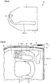
- Each of Figs. 6 and 7 is a diagram showing a construction of the inside of the cab in the wheel loader shown in Fig. 1 .
- cab 10 in the present embodiment mainly includes a floor panel 1, a plurality of pillars 2A and 2B, a roof portion 3, a front portion 4, a pair of left and right front sidewalls 5, a pair of left and right central sidewalls 6, a pair of left and right rear sidewalls 7, a rear portion 8, an air-conditioning unit 12, operator seat 14, and a front console 15F.
- the plurality of pillars 2A, 2B include a pair of left and right front pillars 2A and a pair of left and right rear pillars 2B.
- the pair of left and right front pillars 2A and the pair of left and right rear pillars 2B are erected on floor panel 1.
- the pair of left and right front pillars 2A and the pair of left and right rear pillars 2B are each arranged such that a longitudinal direction thereof vertically extends.
- Front pillars 2A and rear pillars 2B are arranged in this order in cab 10 as being aligned from the front toward the rear.
- Roof portion 3 is arranged in an upper portion of cab 10 and supported by the plurality of pillars 2A and 2B with respect to floor panel 1.
- a beam member (not shown) is connected to each of an upper end portion of front pillar 2A and an upper end portion of rear pillar 2B and connected to roof portion 3.
- Front portion 4 is arranged in a front part of cab 10.
- Front portion 4 includes a front window 4a and an exterior panel 4b.
- Front window 4a is arranged above exterior panel 4b.
- Rear portion 8 is arranged in a rear part of cab 10.
- Rear portion 8 includes a rear window 8a and an exterior panel 8b.
- Rear window 8a is arranged above exterior panel 8b.
- Central sidewall 6 is arranged between front pillar 2A and rear pillar 2B.
- Central sidewall 6 may be provided as a door for boarding.
- door for boarding 6 is supported, for example, by rear pillar 2B for opening and closing.
- Door for boarding 6 serves as a port of entry and exit for an operator who operates wheel loader 50.
- Central sidewall 6 may be fixed (permanently set) as being fitted between front pillar 2A and rear pillar 2B.
- Front sidewall 5 extends forward from front pillar 2A. Front sidewall 5 is arranged between front pillar 2A and front portion 4. Rear sidewall 7 extends rearward from rear pillar 2B. Rear sidewall 7 is arranged between rear pillar 2B and rear portion 8. Front portion 4 and front sidewall 5 define a front wall.
- Air-conditioning unit 12, operator seat 14, and front console 15F are each arranged in cab 10.
- Front console 15F is arranged in front of operator seat 14.
- Front console 15F includes a front operation panel (front operation portion).
- the front operation panel includes, for example, a parking brake switch, an electronic controlled suspension system (ECSS) switch, a working light switch, and a wiper switch.
- ECSS electronic controlled suspension system
- Air-conditioning unit 12 is arranged in front of operator seat 14 below front console 15F.
- Air-conditioning unit 12 includes an indoor and outdoor air switch door, a fan, an evaporator, a heater core, and the like.
- the fan takes in indoor air and outdoor air into the air-conditioning unit, sends air to the evaporator and the heater core, and thereafter sends air into an internal space in the operator's cab. Air in the internal space in cab 10 is thus conditioned.
- Front window 4a in front portion 4 is arranged above an upper surface of front console 15F.
- Rear window 8a in rear portion 8 is arranged in an upper part of rear portion 8.
- Each of front window 4a and rear window 8a is made from a transparent member (for example, glass) through which the outside can be seen from the inside of cab 10. The operator who is seated at operator seat 14 can thus have a view in front of wheel loader 50 through front window 4a and a view in the rear of wheel loader 50 through rear window 8a.
- each of the pair of left and right central sidewalls 6 is constructed such that the outside can be seen therethrough from the inside of cab 10.
- each of the pair of left and right central sidewalls 6 includes, for example, a frame 6a and a transparent member 6b.
- Transparent member 6b is fitted into frame 6a.
- Transparent member 6b is constructed such that the outside can be seen therethrough from the inside of cab 10, and made, for example, of glass.
- Transparent member 6b may be arranged substantially across central sidewall 6 from an upper end to a lower end thereof in a direction of height.
- a part of central sidewall 6 located under a lower end position (a chain dotted line L in the figure) of front console 15F includes transparent member 6b as a window portion (a second window portion) through which the outside can be seen from the inside of cab 10.
- transparent member 6b of central sidewall 6 may be divided into an upper portion 6ba and a lower portion 6bb by frame 6a.
- lower portion 6bb of transparent member 6b is located under the lower end position (chain dotted line L in the figure: Fig. 2 ) of front console 15F.
- lower portion 6bb located under the lower end position (chain dotted line L in the figure) of front console 15F is provided as the window portion (second window portion) through which the outside can be seen from the inside of cab 10.
- the operator who is seated at operator seat 14 can thus have a view laterally below and laterally above wheel loader 50 through transparent member 6b of central sidewall 6.
- the lower end position (chain dotted line L in the figure) of front console 15F means a lowest position of a lower surface of front console 15F located above an accelerator pedal or a brake pedal.
- each of the pair of left and right front sidewalls 5 includes an upper window 5U and a lower window 5L (a first window portion).
- Upper window 5U is located above the upper surface of front console 15F.
- Lower window 5L is located below the lower end position (chain dotted line L in the figure: Fig. 2 ) of front console 15F.
- Lower window 5L is arranged in front of operator seat 14 and laterally to air-conditioning unit 12. Laterally to air-conditioning unit 12 means a lateral side up to a height position as high as a height position of air-conditioning unit 12 with at least floor panel 1 being defined as the reference.
- Each of upper window 5U and lower window 5L is made from a transparent member (for example, glass) through which the outside can be seen from the inside of cab 10.
- the operator who is seated at operator seat 14 can thus have a view obliquely forward above wheel loader 50 through upper window 5U and a view obliquely forward below wheel loader 50 through lower window 5L.
- Both of the pair of left and right front sidewalls 5 include lower window 5L.
- Upper window 5U and lower window 5L may form a single window (a single seamless window) without being separated from each other.
- a transparent member such as glass may be fitted, or may not be fitted so that the inside and the outside of cab 10 communicate with each other through upper window 5U and lower window 5L.
- Each of the pair of left and right rear sidewalls 7 includes a window 7a and an exterior panel 7b.
- Window 7a is arranged above exterior panel 7b.
- Window 7a is made, for example, from a transparent member (for example, glass) through which the outside can be seen from the inside of cab 10. The operator who is seated at operator seat 14 can thus have a view obliquely behind wheel loader 50 through window 7a.
- Rear sidewall 7 includes an outdoor air suction inlet 7c.
- exterior panel 7b in one of the pair of left and right rear sidewalls 7 includes outdoor air suction inlet 7c.
- Outdoor air suction inlet 7c serves to supply air (outdoor air) to air-conditioning unit 12.
- Outdoor air suction inlet 7c is defined, for example, by a plurality of slits 7ca. Each of the plurality of slits 7ca passes through exterior panel 7b.
- Outdoor air suction inlet 7c includes a part located under the lower end position (chain dotted line L in the figure: Fig. 2 ) of front console 15F.
- Exterior panel 7b of rear sidewall 7 may be integrated with exterior panel 8b of rear portion 8. Exterior panel 7b of rear sidewall 7 may serve as a cover which can be opened and closed with respect to exterior panel 8b of rear portion 8.
- a filter 9 is preferably replaceable from the outside of wheel loader 50 by opening exterior panel 7b. An operation for replacing filter 9 is thus facilitated.
- a distance W between the pair of left and right front sidewalls 5 decreases from the rear toward the front.
- the plan view means a point of view of roof portion 3 or floor panel 1 in a direction orthogonal to an upper surface of roof portion 3 or an upper surface of floor panel 1.
- Each of the pair of left and right front sidewalls 5 is inclined with respect to central sidewall 6 in the plan view.
- filter 9 is arranged on an inner side of outdoor air suction inlet 7c in exterior panel 7b.
- Filter 9 is made, for example, from a nonwoven fabric sheet.
- Filter 9 serves to clean air by removing dust or the like from air suctioned through outdoor air suction inlet 7c.
- Filter 9 is arranged along exterior panel 7b.
- Filter 9 is arranged between outdoor air suction inlet 7c and a duct 11.
- Duct 11 serves to guide outdoor air through outdoor air suction inlet 7c to air-conditioning unit 12.
- Duct 11 includes an indoor duct 11a and an outdoor duct 11b.
- Indoor duct 11a is arranged in cab 10.
- Indoor duct 11a has one opening end covered with filter 9.
- Indoor duct 11a has the other opening end supported by floor panel 1.
- a through hole is provided in a portion of floor panel 1 which supports the other opening end of indoor duct 11a. At least a part of duct 11 (outdoor duct 11b) is arranged outside cab 10 under floor panel 1. Outdoor duct 11b has one opening end supported by floor panel 1. An internal flow path in outdoor duct 11b and an internal flow path in indoor duct 11a communicate with each other through the through hole provided in floor panel 1.
- outdoor duct 11b is supported on a lower surface of floor panel 1. Outdoor duct 11b extends from a rear position toward a front position in cab 10 and reaches a position directly under air-conditioning unit 12. The internal flow path in outdoor duct 11b communicates with an outdoor air introduction path of air-conditioning unit 12 through a through hole in floor panel 1. Outdoor air taken in through outdoor air suction inlet 7c is thus purified by filter 9 and thereafter supplied to air-conditioning unit 12 through duct 11.
- cab 10 further includes a pair of left and right armrests 14R and 14L, a lateral console 15S, and a controller 16.
- Armrest 14R is arranged, for example, on the right side of operator seat 14.
- Armrest 14L is arranged, for example, on the left side of operator seat 14.
- Lateral console 15S is arranged, for example, on the right side of operator seat 14. Lateral console 15S includes, for example, a work implement lever (an operation apparatus) for operating the work implement. Lateral console 15S includes, for example, a kick down switch, a transmission cut-off switch, a hom switch, a forward and rearward travel switch, and a remote positioner switch.
- Controller 16 is arranged directly under lateral console 15S. Controller 16 serves to control an operation by each component of wheel loader 50. Controller 16 includes, for example, a central processing unit and a storage.
- Controller 16 is transversely mounted on the upper surface of floor panel 1. Specifically, controller 16 is supported on the upper surface of floor panel 1 in such a manner that a lateral dimension thereof in a plane orthogonal to the height direction is longer than a thickness thereof in the direction of height from the upper surface of floor panel 1.
- Lower window 5L and outdoor air suction inlet 7c are located on a lateral side the same as a lateral side where lateral console 15S is arranged with respect to operator seat 14. Specifically, when lateral console 15S is arranged, for example, on the right side of operator seat 14, both of lower window 5L and outdoor air suction inlet 7c are also arranged on the right side with respect to operator seat 14.
- cab 10 further includes an operation portion 13.
- Operation portion 13 is provided in front pillar 2A in cab 10.
- Operation portion 13 is preferably arranged above the upper surface of front console 15F.
- Operation portion 13 is preferably provided to protrude from front pillar 2A into cab 10.
- operation portion 13 is preferably provided to protrude from front pillar 2A toward operator seat 14. The operator can thus readily operate operation portion 13 provided in front pillar 2A in an attitude as seated on operator seat 14.
- a front sidewall 105 includes a window portion 105a and an exterior panel 105b arranged under window portion 105a. Exterior panel 105b is provided with an outdoor air suction inlet 107c for supplying outdoor air to an air-conditioning unit. Outdoor air suction inlet 107c is defined by a plurality of slits 107ca.
- a central sidewall 106 includes a window portion 106b and an exterior panel 106c arranged under window portion 106b.
- cab 110 in such a comparative example an operator who is seated at an operator seat is unable to have a view obliquely forward below a wheel loader due to the presence of exterior panel 105b of front sidewall 105. The operator is also unable to have a view laterally below the wheel loader due to the presence of exterior panel 106c of central sidewall 106.
- outdoor air suction inlet 7c is provided in exterior panel 7b of rear sidewall 7 as shown in Fig. 2 . Therefore, in front sidewall 5, lower window 5L can be arranged under the lower end position (chain dotted line L in the figure: Fig. 2 ) of front console 15F. The operator who is seated at operator seat 14 in cab 10 can thus have a view obliquely forward below wheel loader 50 through lower window 5L in front sidewall 5 so that visibility is good.
- a portion of central sidewall 6 below front console 15F includes transparent member 6b through which the outside can be seen from the inside of cab 10. Therefore, the operator who is seated at operator seat 14 in cab 10 can have a view laterally below wheel loader 50 through transparent member 6b in central sidewall 6 so that visibility is better.
- operation portion 13 is provided in front pillar 2A as shown in Fig. 7 .
- a part of the operation portion which should essentially be arranged in lateral console 15S in Fig. 6 is thus provided in front pillar 2A, so that the number of operation portions provided in lateral console 15S can be reduced.
- Lateral console 15S can thus be reduced in size.
- the vision of the operator who is seated at operator seat 14 is less likely to be blocked by lateral console 15S by an amount equal to reduction in size of lateral console 15S, so that the operator can view the outside of cab 10 over a wider range. Therefore, the operator's visibility is better.
- duct 11 (outdoor duct 11b) is arranged under floor panel 1.
- a space occupied by duct 11 in the indoor space in cab 10 can thus be decreased.
- a component other than duct 11 can be arranged in the indoor space in cab 10 by an amount equal to decrease in space that has been occupied by duct 11, so that the indoor space in cab 10 can effectively be used.
- controller 16 is arranged directly under lateral console 15S as shown in Fig. 6 .
- An area directly under lateral console 15S which has been a dead space can thus effectively be used.
- outdoor air suction inlet 7c can be provided in exterior panel 7b of rear sidewall 7.
- controller 16 in the area directly under lateral console 15S, block by controller 16 of the view from the operator who is seated at operator seat 14 can be suppressed.
- controller 16 Since controller 16 is transversely mounted, a height of controller 16 which protrudes from the upper surface of floor panel 1 can be decreased. Therefore, block by controller 16 of the view from the operator who is seated at operator seat 14 can further be suppressed.
Landscapes
- Engineering & Computer Science (AREA)
- Mechanical Engineering (AREA)
- Mining & Mineral Resources (AREA)
- Transportation (AREA)
- Combustion & Propulsion (AREA)
- Chemical & Material Sciences (AREA)
- Physics & Mathematics (AREA)
- General Engineering & Computer Science (AREA)
- Civil Engineering (AREA)
- Structural Engineering (AREA)
- Thermal Sciences (AREA)
- Geology (AREA)
- Life Sciences & Earth Sciences (AREA)
- Aviation & Aerospace Engineering (AREA)
- Environmental & Geological Engineering (AREA)
- Geochemistry & Mineralogy (AREA)
- General Life Sciences & Earth Sciences (AREA)
- Fluid Mechanics (AREA)
- Component Parts Of Construction Machinery (AREA)
- Air-Conditioning For Vehicles (AREA)
- Body Structure For Vehicles (AREA)
Description
- The present invention relates to a cab for a work vehicle and a work vehicle, and particularly to a cab for a work vehicle and a work vehicle which include an air-conditioning unit.
- A work vehicle including an air-conditioning unit is disclosed, for example, in
JP 2007 154444 A JP 2007 154444 A -
EP 2 664 716 A1 discloses a cab, in particular a cab for a wheel loader. Between a front pillar and a center pillar, a door is disposed for allowing an operator to enter and exit the cab. The cab has an internal space enclosed by a floor plate, a roof, a front window, the door, and other wall portions. In this internal space, a driver's seat for an operator to sit, and an air conditioner are disposed. - A cab for a work vehicle in
US 2015/000996 A1 has an indoor space surrounded by a floor frame, a plurality of pillars, and a roof portion. An air-conditioner is arranged at a lower front end of this indoor space. An appropriate pressure can be provided by the air-conditioner to the indoor space so that dust particles or the like can be prevented from entering the indoor space. - Improvement in operator's visibility of the outside from the inside of a cab in a work vehicle including such an air-conditioning unit has been demanded.
- An object of the present invention is to provide a cab for a work vehicle and a work vehicle which achieve improvement in visibility of the outside from the inside of the cab in the presence of an air-conditioning unit.
- This object is solved according to the present invention by providing a cab for a work vehicle, comprising an operator seat, an air-conditioning unit, and a front wall. The air-conditioning unit is arranged in front of the operator seat. The front wall comprises a pair of left and right front sidewalls and is arranged in front of the operator seat and laterally to the air-conditioning unit. Each of the pair of left and right front sidewalls includes an upper window and a lower window, with each lower window being arranged in front of the operator seat and laterally to the air-conditioning unit and through which outside can be seen from the inside of the cab for the work vehicle.
- A work vehicle according to the present invention comprises the cab for the work vehicle described above and a work implement operated by an operation apparatus provided in the cab for the work vehicle.
- According to the present invention, a cab for a work vehicle and a work vehicle which achieve improvement in visibility of the outside from the inside of the cab in the presence of an air-conditioning unit can be obtained.
-
-
Fig. 1 is a schematic side view showing a construction of a wheel loader representing an example of a work vehicle in one embodiment. -
Fig. 2 is a side view showing a construction of a cab in the wheel loader shown inFig. 1 . -
Fig. 3 is a plan view showing the construction of the cab in the wheel loader shown inFig. 1 . -
Fig. 4 is a schematic cross-sectional view along the line IV-IV inFig. 2 . -
Fig. 5 is a bottom view showing the construction of the cab in the wheel loader shown inFig. 1 . -
Fig. 6 is a plan view showing a construction of the inside of the cab in the wheel loader shown inFig. 1 . -
Fig. 7 is a diagram showing a construction of the inside of the cab in the wheel loader shown inFig. 1 . -
Fig. 8 is a side view showing a construction of a cab in a comparative example. - An embodiment of the present disclosure will be described below with reference to the drawings.
- Initially, a construction of a work vehicle in one embodiment of the present disclosure will be described. A wheel loader representing one example of a work vehicle to which the concept of the present disclosure can be applied will be described below with reference to
Fig. 1 . The present disclosure is applicable also to a work vehicle such as a hydraulic excavator, a crawler dozer, and a crane other than the wheel loader. - In the present example, positional relation of portions will be described with an operator who is seated at an
operator seat 14 in acab 10 being defined as the reference. A fore/aft direction refers to front and rear directions of the operator who is seated at the operator seat. A lateral direction (a width direction) refers to left and right directions of the operator who is seated at the operator seat. A vertical direction refers to upward and downward directions of the operator who is seated at the operator seat. - A direction which the operator seated at the operator seat faces is the fore direction, and a direction opposite to the fore direction is the aft direction. The right side and the left side at the time when the operator seated at the operator seat faces the front is right and left directions, respectively. A foot side of the operator who is seated at the operator seat refers to a lower side and a head side refers to an upper side.
-
Fig. 1 is a schematic side view showing a construction of a wheel loader representing an example of a work vehicle in one embodiment. As shown inFig. 1 , awheel loader 50 in the present embodiment mainly has afront frame 42, a rearvehicular body 44, and a work implement 30. Afront wheel 43a is attached to each of opposing side portions offront frame 42. Arear wheel 43b is attached to each of opposing side portions of rearvehicular body 44. -
Front frame 42 and rearvehicular body 44 are attached to each other to freely laterally be actuated by means of a center pin (not shown).Front frame 42 and rearvehicular body 44 implement an articulated structure. - Specifically,
front frame 42 and rearvehicular body 44 are coupled to each other by a pair of left and right steering cylinders (not shown). As these left and right steering cylinders extend and contract,front frame 42 and rearvehicular body 44 are laterally actuated and steered around the center pin.Front frame 42 and rearvehicular body 44 implement a vehicular body ofwheel loader 50. -
Work implement 30 is attached in front offront frame 42.Work implement 30 has a pair ofbooms 31, abucket 32, and a pair ofboom cylinders 33. - An engine compartment 44b is arranged in rear
vehicular body 44. - Rear
vehicular body 44 has a cab (an operator's cab) 10 in front of engine compartment 44b.Cab 10 defines a space for an operator to operatewheel loader 50 inside. - A construction of
cab 10 will now be described with reference toFigs. 2 to 7 . -
Figs. 2 and3 are a side view and a plan view showing a construction of the cab in the wheel loader shown inFig. 1 , respectively.Fig. 4 is a schematic cross-sectional view along the line IV-IV inFig. 2 .Fig. 5 is a bottom view showing the construction of the cab in the wheel loader shown inFig. 1 . Each ofFigs. 6 and7 is a diagram showing a construction of the inside of the cab in the wheel loader shown inFig. 1 . - As shown in
Fig. 2 ,cab 10 in the present embodiment mainly includes afloor panel 1, a plurality ofpillars roof portion 3, afront portion 4, a pair of left and rightfront sidewalls 5, a pair of left and rightcentral sidewalls 6, a pair of left and rightrear sidewalls 7, arear portion 8, an air-conditioning unit 12,operator seat 14, and afront console 15F. - The plurality of
pillars front pillars 2A and a pair of left and rightrear pillars 2B. The pair of left and rightfront pillars 2A and the pair of left and rightrear pillars 2B are erected onfloor panel 1. The pair of left and rightfront pillars 2A and the pair of left and rightrear pillars 2B are each arranged such that a longitudinal direction thereof vertically extends.Front pillars 2A andrear pillars 2B are arranged in this order incab 10 as being aligned from the front toward the rear. -
Roof portion 3 is arranged in an upper portion ofcab 10 and supported by the plurality ofpillars floor panel 1. A beam member (not shown) is connected to each of an upper end portion offront pillar 2A and an upper end portion ofrear pillar 2B and connected toroof portion 3. -
Front portion 4 is arranged in a front part ofcab 10.Front portion 4 includes afront window 4a and anexterior panel 4b.Front window 4a is arranged aboveexterior panel 4b.Rear portion 8 is arranged in a rear part ofcab 10.Rear portion 8 includes arear window 8a and anexterior panel 8b.Rear window 8a is arranged aboveexterior panel 8b. -
Central sidewall 6 is arranged betweenfront pillar 2A andrear pillar 2B.Central sidewall 6 may be provided as a door for boarding. Whencentral sidewall 6 is provided as the door for boarding, door for boarding 6 is supported, for example, byrear pillar 2B for opening and closing. Door for boarding 6 serves as a port of entry and exit for an operator who operateswheel loader 50.Central sidewall 6 may be fixed (permanently set) as being fitted betweenfront pillar 2A andrear pillar 2B. -
Front sidewall 5 extends forward fromfront pillar 2A.Front sidewall 5 is arranged betweenfront pillar 2A andfront portion 4.Rear sidewall 7 extends rearward fromrear pillar 2B.Rear sidewall 7 is arranged betweenrear pillar 2B andrear portion 8.Front portion 4 andfront sidewall 5 define a front wall. - Air-
conditioning unit 12,operator seat 14, andfront console 15F are each arranged incab 10.Front console 15F is arranged in front ofoperator seat 14.Front console 15F includes a front operation panel (front operation portion). The front operation panel includes, for example, a parking brake switch, an electronic controlled suspension system (ECSS) switch, a working light switch, and a wiper switch. - Air-
conditioning unit 12 is arranged in front ofoperator seat 14 belowfront console 15F. Air-conditioning unit 12 includes an indoor and outdoor air switch door, a fan, an evaporator, a heater core, and the like. The fan takes in indoor air and outdoor air into the air-conditioning unit, sends air to the evaporator and the heater core, and thereafter sends air into an internal space in the operator's cab. Air in the internal space incab 10 is thus conditioned. -
Front window 4a infront portion 4 is arranged above an upper surface offront console 15F.Rear window 8a inrear portion 8 is arranged in an upper part ofrear portion 8. Each offront window 4a andrear window 8a is made from a transparent member (for example, glass) through which the outside can be seen from the inside ofcab 10. The operator who is seated atoperator seat 14 can thus have a view in front ofwheel loader 50 throughfront window 4a and a view in the rear ofwheel loader 50 throughrear window 8a. - Each of the pair of left and right
central sidewalls 6 is constructed such that the outside can be seen therethrough from the inside ofcab 10. Specifically, each of the pair of left and rightcentral sidewalls 6 includes, for example, aframe 6a and atransparent member 6b.Transparent member 6b is fitted intoframe 6a.Transparent member 6b is constructed such that the outside can be seen therethrough from the inside ofcab 10, and made, for example, of glass. -
Transparent member 6b may be arranged substantially acrosscentral sidewall 6 from an upper end to a lower end thereof in a direction of height. In this case, a part ofcentral sidewall 6 located under a lower end position (a chain dotted line L in the figure) offront console 15F includestransparent member 6b as a window portion (a second window portion) through which the outside can be seen from the inside ofcab 10. - As shown in
Fig. 1 ,transparent member 6b ofcentral sidewall 6 may be divided into an upper portion 6ba and a lower portion 6bb byframe 6a. In this case, lower portion 6bb oftransparent member 6b is located under the lower end position (chain dotted line L in the figure:Fig. 2 ) offront console 15F. In this case, lower portion 6bb located under the lower end position (chain dotted line L in the figure) offront console 15F is provided as the window portion (second window portion) through which the outside can be seen from the inside ofcab 10. The operator who is seated atoperator seat 14 can thus have a view laterally below and laterally abovewheel loader 50 throughtransparent member 6b ofcentral sidewall 6. - The lower end position (chain dotted line L in the figure) of
front console 15F means a lowest position of a lower surface offront console 15F located above an accelerator pedal or a brake pedal. - As shown in
Fig. 2 , each of the pair of left and rightfront sidewalls 5 includes anupper window 5U and alower window 5L (a first window portion).Upper window 5U is located above the upper surface offront console 15F.Lower window 5L is located below the lower end position (chain dotted line L in the figure:Fig. 2 ) offront console 15F.Lower window 5L is arranged in front ofoperator seat 14 and laterally to air-conditioning unit 12. Laterally to air-conditioning unit 12 means a lateral side up to a height position as high as a height position of air-conditioning unit 12 with at leastfloor panel 1 being defined as the reference. - Each of
upper window 5U andlower window 5L is made from a transparent member (for example, glass) through which the outside can be seen from the inside ofcab 10. The operator who is seated atoperator seat 14 can thus have a view obliquely forward abovewheel loader 50 throughupper window 5U and a view obliquely forward belowwheel loader 50 throughlower window 5L. - Both of the pair of left and right
front sidewalls 5 includelower window 5L.Upper window 5U andlower window 5L may form a single window (a single seamless window) without being separated from each other. In each ofupper window 5U andlower window 5L, a transparent member such as glass may be fitted, or may not be fitted so that the inside and the outside ofcab 10 communicate with each other throughupper window 5U andlower window 5L. - Each of the pair of left and right
rear sidewalls 7 includes awindow 7a and anexterior panel 7b.Window 7a is arranged aboveexterior panel 7b.Window 7a is made, for example, from a transparent member (for example, glass) through which the outside can be seen from the inside ofcab 10. The operator who is seated atoperator seat 14 can thus have a view obliquely behindwheel loader 50 throughwindow 7a. -
Rear sidewall 7 includes an outdoorair suction inlet 7c. Specifically,exterior panel 7b in one of the pair of left and rightrear sidewalls 7 includes outdoorair suction inlet 7c. Outdoorair suction inlet 7c serves to supply air (outdoor air) to air-conditioning unit 12. Outdoorair suction inlet 7c is defined, for example, by a plurality of slits 7ca. Each of the plurality of slits 7ca passes throughexterior panel 7b. Outdoorair suction inlet 7c includes a part located under the lower end position (chain dotted line L in the figure:Fig. 2 ) offront console 15F. -
Exterior panel 7b ofrear sidewall 7 may be integrated withexterior panel 8b ofrear portion 8.Exterior panel 7b ofrear sidewall 7 may serve as a cover which can be opened and closed with respect toexterior panel 8b ofrear portion 8. In this case, afilter 9 is preferably replaceable from the outside ofwheel loader 50 by openingexterior panel 7b. An operation for replacingfilter 9 is thus facilitated. - As shown in
Fig. 3 , in a plan view, a distance W between the pair of left and rightfront sidewalls 5 decreases from the rear toward the front. The plan view means a point of view ofroof portion 3 orfloor panel 1 in a direction orthogonal to an upper surface ofroof portion 3 or an upper surface offloor panel 1. Each of the pair of left and rightfront sidewalls 5 is inclined with respect tocentral sidewall 6 in the plan view. - As shown in
Fig. 4 ,filter 9 is arranged on an inner side of outdoorair suction inlet 7c inexterior panel 7b.Filter 9 is made, for example, from a nonwoven fabric sheet.Filter 9 serves to clean air by removing dust or the like from air suctioned through outdoorair suction inlet 7c.Filter 9 is arranged alongexterior panel 7b.Filter 9 is arranged between outdoorair suction inlet 7c and aduct 11. -
Duct 11 serves to guide outdoor air through outdoorair suction inlet 7c to air-conditioning unit 12.Duct 11 includes anindoor duct 11a and anoutdoor duct 11b.Indoor duct 11a is arranged incab 10.Indoor duct 11a has one opening end covered withfilter 9.Indoor duct 11a has the other opening end supported byfloor panel 1. - A through hole is provided in a portion of
floor panel 1 which supports the other opening end ofindoor duct 11a. At least a part of duct 11 (outdoor duct 11b) is arranged outsidecab 10 underfloor panel 1.Outdoor duct 11b has one opening end supported byfloor panel 1. An internal flow path inoutdoor duct 11b and an internal flow path inindoor duct 11a communicate with each other through the through hole provided infloor panel 1. - As shown in
Fig. 5 ,outdoor duct 11b is supported on a lower surface offloor panel 1.Outdoor duct 11b extends from a rear position toward a front position incab 10 and reaches a position directly under air-conditioning unit 12. The internal flow path inoutdoor duct 11b communicates with an outdoor air introduction path of air-conditioning unit 12 through a through hole infloor panel 1. Outdoor air taken in through outdoorair suction inlet 7c is thus purified byfilter 9 and thereafter supplied to air-conditioning unit 12 throughduct 11. - As shown in
Fig. 6 ,cab 10 further includes a pair of left andright armrests lateral console 15S, and acontroller 16.Armrest 14R is arranged, for example, on the right side ofoperator seat 14.Armrest 14L is arranged, for example, on the left side ofoperator seat 14. -
Lateral console 15S is arranged, for example, on the right side ofoperator seat 14.Lateral console 15S includes, for example, a work implement lever (an operation apparatus) for operating the work implement.Lateral console 15S includes, for example, a kick down switch, a transmission cut-off switch, a hom switch, a forward and rearward travel switch, and a remote positioner switch. -
Controller 16 is arranged directly underlateral console 15S.Controller 16 serves to control an operation by each component ofwheel loader 50.Controller 16 includes, for example, a central processing unit and a storage. -
Controller 16 is transversely mounted on the upper surface offloor panel 1. Specifically,controller 16 is supported on the upper surface offloor panel 1 in such a manner that a lateral dimension thereof in a plane orthogonal to the height direction is longer than a thickness thereof in the direction of height from the upper surface offloor panel 1. -
Lower window 5L and outdoorair suction inlet 7c are located on a lateral side the same as a lateral side wherelateral console 15S is arranged with respect tooperator seat 14. Specifically, whenlateral console 15S is arranged, for example, on the right side ofoperator seat 14, both oflower window 5L and outdoorair suction inlet 7c are also arranged on the right side with respect tooperator seat 14. - As shown in
Fig. 7 ,cab 10 further includes anoperation portion 13.Operation portion 13 is provided infront pillar 2A incab 10.Operation portion 13 is preferably arranged above the upper surface offront console 15F.Operation portion 13 is preferably provided to protrude fromfront pillar 2A intocab 10. - More specifically,
operation portion 13 is preferably provided to protrude fromfront pillar 2A towardoperator seat 14. The operator can thus readily operateoperation portion 13 provided infront pillar 2A in an attitude as seated onoperator seat 14. - A function and effect of the present embodiment will now be described as compared to a construction of a
cab 110 in a comparative example shown inFig. 8 . - As shown in
Fig. 8 , incab 110 in the comparative example, afront sidewall 105 includes awindow portion 105a and an exterior panel 105b arranged underwindow portion 105a. Exterior panel 105b is provided with an outdoorair suction inlet 107c for supplying outdoor air to an air-conditioning unit. Outdoorair suction inlet 107c is defined by a plurality of slits 107ca. Acentral sidewall 106 includes awindow portion 106b and anexterior panel 106c arranged underwindow portion 106b. - In
cab 110 in such a comparative example, an operator who is seated at an operator seat is unable to have a view obliquely forward below a wheel loader due to the presence of exterior panel 105b offront sidewall 105. The operator is also unable to have a view laterally below the wheel loader due to the presence ofexterior panel 106c ofcentral sidewall 106. - In contrast, in the present embodiment, outdoor
air suction inlet 7c is provided inexterior panel 7b ofrear sidewall 7 as shown inFig. 2 . Therefore, infront sidewall 5,lower window 5L can be arranged under the lower end position (chain dotted line L in the figure:Fig. 2 ) offront console 15F. The operator who is seated atoperator seat 14 incab 10 can thus have a view obliquely forward belowwheel loader 50 throughlower window 5L infront sidewall 5 so that visibility is good. - In the present embodiment, a portion of
central sidewall 6 belowfront console 15F includestransparent member 6b through which the outside can be seen from the inside ofcab 10. Therefore, the operator who is seated atoperator seat 14 incab 10 can have a view laterally belowwheel loader 50 throughtransparent member 6b incentral sidewall 6 so that visibility is better. - In the present embodiment,
operation portion 13 is provided infront pillar 2A as shown inFig. 7 . A part of the operation portion which should essentially be arranged inlateral console 15S inFig. 6 is thus provided infront pillar 2A, so that the number of operation portions provided inlateral console 15S can be reduced.Lateral console 15S can thus be reduced in size. The vision of the operator who is seated atoperator seat 14 is less likely to be blocked bylateral console 15S by an amount equal to reduction in size oflateral console 15S, so that the operator can view the outside ofcab 10 over a wider range. Therefore, the operator's visibility is better. - In the present embodiment, as shown in
Figs. 4 and5 , at least a part of duct 11 (outdoor duct 11b) is arranged underfloor panel 1. A space occupied byduct 11 in the indoor space incab 10 can thus be decreased. A component other thanduct 11 can be arranged in the indoor space incab 10 by an amount equal to decrease in space that has been occupied byduct 11, so that the indoor space incab 10 can effectively be used. - In the present embodiment,
controller 16 is arranged directly underlateral console 15S as shown inFig. 6 . An area directly underlateral console 15S which has been a dead space can thus effectively be used. By arrangingcontroller 16 directly underlateral console 15S, outdoorair suction inlet 7c can be provided inexterior panel 7b ofrear sidewall 7. By arrangingcontroller 16 in the area directly underlateral console 15S, block bycontroller 16 of the view from the operator who is seated atoperator seat 14 can be suppressed. - Since
controller 16 is transversely mounted, a height ofcontroller 16 which protrudes from the upper surface offloor panel 1 can be decreased. Therefore, block bycontroller 16 of the view from the operator who is seated atoperator seat 14 can further be suppressed. - It should be understood that the embodiment disclosed herein is illustrative and non-restrictive in every respect. The scope of the present invention is defined by the terms of the claims rather than the description above and is intended to include any modifications within the scope and meaning equivalent to the terms of the claims.
- 1 floor panel; 2A front pillar; 2B rear pillar; 3 roof portion; 4 front portion; 4a front window; 4b, 7b, 8b exterior panel; 5 front sidewall; 5L lower window; 5U upper window; 6 central sidewall; 6a frame; 6b transparent member; 6ba upper portion; 6bb lower portion; 7 rear sidewall; 7a window; 7c outdoor air suction inlet; 7ca slit; 8 rear portion; 8a rear window; 9 filter; 10 cab; 11 duct; 11a indoor duct; 11b outdoor duct; 12 air-conditioning unit; 13 operation portion; 14 operator seat; 14L, 14R armrest; 15F front console; 15S lateral console; 16 controller; 30 work implement; 31 boom; 32 bucket; 33 boom cylinder; 42 front frame; 43a front wheel; 43b rear wheel; 44 rear vehicular body; 44a hydraulic oil tank; 44b engine compartment; 44d counterweight; 50 wheel loader
Claims (11)
- A cab (10) for a work vehicle (50), comprising:an operator seat (14);an air-conditioning unit (12) arranged in front of the operator seat (14); anda front wall (4, 5) comprising a pair of left and right front sidewalls (5) arranged in front of the operator seat (14) and laterally to the air-conditioning unit (12),characterized in thateach of the pair of left and right front sidewalls (5) includes an upper window (5U) and a lower window (5L), with each lower window (5L) being arranged in front of the operator seat (14) and laterally to the air-conditioning unit (12) and through which outside can be seen from inside of the cab (10) for the work vehicle (50).
- The cab (10) for a work vehicle (50) according to claim 1, further comprising a rear sidewall (7) arranged in rear of the operator seat (14), wherein
the rear sidewall (7) includes an outdoor air suction inlet (7c) for supplying air to the air-conditioning unit (12). - The cab (10) for a work vehicle (50) according to claim 2, further comprising:a floor panel (1) located under the operator seat (14); anda duct (11) which guides air from the outdoor air suction inlet (7c) to the air-conditioning unit (12), whereinat least a part of the duct (11) is arranged under the floor panel (1).
- The cab (10) for a work vehicle (50) according to claim 1, further comprising a front console (15S) arranged in front of the operator seat (14), wherein
the lower window (5L) is arranged under the front console (15S). - The cab (10) for a work vehicle (50) according to claim 1, further comprising a front pillar (2A), wherein
the front sidewall (5) extends forward from the front pillar (2A). - The cab (10) for a work vehicle (50) according to claim 4, further comprising a central sidewall (6) arranged laterally to the operator seat (14), wherein
a part of the central sidewall (6) located under a lower end (L) of the front console (15F) includes a window portion (6b) through which the outside can be seen from the inside of the cab (10) for the work vehicle (50). - The cab (10) for a work vehicle according to claim 6, further comprising:a front pillar (2A); anda rear pillar (2B) located in the rear of the front pillar (2A), whereinthe central sidewall (6) is arranged between the front pillar (2A) and the rear pillar (2B).
- The cab (10) for a work vehicle (50) according to claim 1, further comprising:a lateral console (15S) arranged laterally to the operator seat (14); anda controller (16), whereinthe controller (16) is arranged directly under the lateral console (15S).
- The cab (10) for a work vehicle (50) according to claim 2, further comprising a lateral console (15S) arranged laterally to the operator seat (14), wherein
the lower window (5L) and the outdoor air suction inlet (7c) are located on a lateral side identical to a lateral side where the lateral console (15S) is arranged with respect to the operator seat (14). - The cab (10) for a work vehicle (50) according to claim 1, further comprising an operation portion (13) provided in the front pillar (2A) in the cab (10) for the work vehicle (50).
- A work vehicle (50), comprising:the cab (10) for the work vehicle (50) according to any one of claims 1 to 9; anda work implement (30) operated by an operation apparatus provided in the cab (10) of the work vehicle (50).
Applications Claiming Priority (2)
| Application Number | Priority Date | Filing Date | Title |
|---|---|---|---|
| JP2017123915A JP6824118B2 (en) | 2017-06-26 | 2017-06-26 | Work vehicle cab and work vehicle |
| PCT/JP2018/021332 WO2019003808A1 (en) | 2017-06-26 | 2018-06-04 | Cab for working vehicle, and working vehicle |
Publications (3)
| Publication Number | Publication Date |
|---|---|
| EP3550082A1 EP3550082A1 (en) | 2019-10-09 |
| EP3550082A4 EP3550082A4 (en) | 2020-05-06 |
| EP3550082B1 true EP3550082B1 (en) | 2021-09-08 |
Family
ID=64741542
Family Applications (1)
| Application Number | Title | Priority Date | Filing Date |
|---|---|---|---|
| EP18823718.4A Active EP3550082B1 (en) | 2017-06-26 | 2018-06-04 | Cab for work vehicle and work vehicle |
Country Status (5)
| Country | Link |
|---|---|
| US (1) | US11673447B2 (en) |
| EP (1) | EP3550082B1 (en) |
| JP (1) | JP6824118B2 (en) |
| CN (1) | CN110234817A (en) |
| WO (1) | WO2019003808A1 (en) |
Families Citing this family (5)
| Publication number | Priority date | Publication date | Assignee | Title |
|---|---|---|---|---|
| EP3950444B1 (en) | 2019-03-29 | 2024-02-28 | Kubota Corporation | Work machine |
| JP7191756B2 (en) * | 2019-03-29 | 2022-12-19 | 株式会社クボタ | work machine |
| CN110962951A (en) * | 2019-12-17 | 2020-04-07 | 东风商用车有限公司 | Truck cab structure capable of maximizing carriage length |
| US20240191466A1 (en) * | 2022-12-12 | 2024-06-13 | Great Plains Manufacturing, Inc. | Slide up cab door for work machine |
| CN117184254A (en) * | 2023-10-26 | 2023-12-08 | 一汽解放汽车有限公司 | Commercial vehicle cab |
Family Cites Families (23)
| Publication number | Priority date | Publication date | Assignee | Title |
|---|---|---|---|---|
| JPS5980572U (en) | 1982-11-21 | 1984-05-31 | 日立建機株式会社 | Cab of construction machinery, etc. |
| JP3189287B2 (en) * | 1991-04-12 | 2001-07-16 | 井関農機株式会社 | Agricultural traveling vehicle air conditioning system |
| US5413188A (en) | 1991-10-18 | 1995-05-09 | Kabushiki Kaisha Komatsu Seisakusho | Operator cabin of bulldozer |
| JP3180925B2 (en) * | 1991-10-18 | 2001-07-03 | 株式会社小松製作所 | Bulldoza cab |
| US5273340A (en) * | 1992-10-19 | 1993-12-28 | Caterpillar Inc. | Cab assembly |
| JP3557862B2 (en) | 1997-08-20 | 2004-08-25 | 井関農機株式会社 | Tractor air conditioner mounting device |
| JP2004322980A (en) * | 2003-04-28 | 2004-11-18 | Sumitomo (Shi) Construction Machinery Manufacturing Co Ltd | Driver's cab for construction machinery |
| JP4318170B2 (en) * | 2003-08-25 | 2009-08-19 | 株式会社小松製作所 | Construction machinery |
| JP2005153834A (en) | 2003-11-28 | 2005-06-16 | Sanden Corp | Air conditioner for vehicle |
| JP2006342583A (en) * | 2005-06-09 | 2006-12-21 | Shin Caterpillar Mitsubishi Ltd | Monitor device in construction machine |
| JP2007001433A (en) | 2005-06-23 | 2007-01-11 | Shin Caterpillar Mitsubishi Ltd | Anti-dew apparatus for cab |
| JP4945122B2 (en) * | 2005-12-01 | 2012-06-06 | 株式会社小松製作所 | Construction machinery cab |
| JP4681502B2 (en) | 2006-05-18 | 2011-05-11 | 株式会社クボタ | Air conditioning structure of tractor |
| JP2008106522A (en) * | 2006-10-26 | 2008-05-08 | Komatsu Ltd | Motor grader cab |
| EP2180100B1 (en) | 2007-08-13 | 2012-10-24 | Hitachi Construction Machinery Co., Ltd | Construction machine |
| JP2011001775A (en) * | 2009-06-19 | 2011-01-06 | Caterpillar Sarl | Display device for construction machine |
| KR20120140122A (en) | 2011-06-20 | 2012-12-28 | 볼보 컨스트럭션 이큅먼트 에이비 | Arm rest for construction machine |
| JP5208290B1 (en) * | 2012-02-23 | 2013-06-12 | 株式会社小松製作所 | Work vehicle cab and work vehicle |
| JP5118259B1 (en) | 2012-03-30 | 2013-01-16 | 株式会社小松製作所 | Cab |
| JP5536964B1 (en) * | 2013-03-26 | 2014-07-02 | 株式会社小松製作所 | Construction machinery cab and construction machinery |
| KR101656196B1 (en) * | 2014-10-24 | 2016-09-08 | 가부시키가이샤 고마쓰 세이사쿠쇼 | Cab and work machine |
| CN107407070B (en) * | 2015-10-30 | 2020-10-27 | 株式会社小松制作所 | work vehicle |
| CN108602539B (en) * | 2016-02-05 | 2021-12-10 | 克拉克设备公司 | Crawler-type multifunctional vehicle |
-
2017
- 2017-06-26 JP JP2017123915A patent/JP6824118B2/en active Active
-
2018
- 2018-06-04 US US16/479,650 patent/US11673447B2/en active Active
- 2018-06-04 CN CN201880009826.0A patent/CN110234817A/en active Pending
- 2018-06-04 EP EP18823718.4A patent/EP3550082B1/en active Active
- 2018-06-04 WO PCT/JP2018/021332 patent/WO2019003808A1/en not_active Ceased
Also Published As
| Publication number | Publication date |
|---|---|
| CN110234817A (en) | 2019-09-13 |
| WO2019003808A1 (en) | 2019-01-03 |
| EP3550082A4 (en) | 2020-05-06 |
| EP3550082A1 (en) | 2019-10-09 |
| JP2019007227A (en) | 2019-01-17 |
| US20210354766A1 (en) | 2021-11-18 |
| JP6824118B2 (en) | 2021-02-03 |
| US11673447B2 (en) | 2023-06-13 |
Similar Documents
| Publication | Publication Date | Title |
|---|---|---|
| EP3550082B1 (en) | Cab for work vehicle and work vehicle | |
| EP3536863B1 (en) | Work vehicle cab, work vehicle, and wheel loader | |
| CN103403267B (en) | Work vehicle cab and work vehicle | |
| JP5536964B1 (en) | Construction machinery cab and construction machinery | |
| EP2918436B1 (en) | Vehicle body cover and work vehicle | |
| CN103429827B (en) | Work vehicle | |
| US6290286B1 (en) | Construction machine | |
| JP4648963B2 (en) | Working unit structure | |
| US9027687B2 (en) | Cab, and work vehicle | |
| EP3932783A1 (en) | Construction machine | |
| US9574325B2 (en) | Work vehicle and cab for work vehicle | |
| JP5183822B1 (en) | Work vehicle cab and work vehicle | |
| KR20200035487A (en) | Working vehicle | |
| WO2015147231A1 (en) | Working vehicle | |
| JP2015193306A (en) | work vehicle | |
| JP6177176B2 (en) | Work vehicle | |
| JP2015189450A (en) | Work vehicle | |
| JP2015190276A (en) | work vehicle | |
| JP2007106272A (en) | Cab and work machine |
Legal Events
| Date | Code | Title | Description |
|---|---|---|---|
| STAA | Information on the status of an ep patent application or granted ep patent |
Free format text: STATUS: THE INTERNATIONAL PUBLICATION HAS BEEN MADE |
|
| PUAI | Public reference made under article 153(3) epc to a published international application that has entered the european phase |
Free format text: ORIGINAL CODE: 0009012 |
|
| STAA | Information on the status of an ep patent application or granted ep patent |
Free format text: STATUS: REQUEST FOR EXAMINATION WAS MADE |
|
| 17P | Request for examination filed |
Effective date: 20190704 |
|
| AK | Designated contracting states |
Kind code of ref document: A1 Designated state(s): AL AT BE BG CH CY CZ DE DK EE ES FI FR GB GR HR HU IE IS IT LI LT LU LV MC MK MT NL NO PL PT RO RS SE SI SK SM TR |
|
| AX | Request for extension of the european patent |
Extension state: BA ME |
|
| RIC1 | Information provided on ipc code assigned before grant |
Ipc: B62D 33/06 20060101ALI20200203BHEP Ipc: B60H 1/00 20060101ALI20200203BHEP Ipc: E02F 3/34 20060101ALI20200203BHEP Ipc: E02F 9/16 20060101AFI20200203BHEP Ipc: E02D 17/13 20060101ALI20200203BHEP Ipc: B60J 1/02 20060101ALI20200203BHEP Ipc: E21B 3/00 20060101ALI20200203BHEP Ipc: E01C 19/00 20060101ALI20200203BHEP Ipc: A01B 1/00 20060101ALI20200203BHEP Ipc: F24F 1/00 20190101ALI20200203BHEP Ipc: E02F 9/00 20060101ALI20200203BHEP |
|
| A4 | Supplementary search report drawn up and despatched |
Effective date: 20200408 |
|
| RIC1 | Information provided on ipc code assigned before grant |
Ipc: A01B 1/00 20060101ALI20200402BHEP Ipc: B60J 1/02 20060101ALI20200402BHEP Ipc: F24F 1/00 20190101ALI20200402BHEP Ipc: E01C 19/00 20060101ALI20200402BHEP Ipc: E02F 3/34 20060101ALI20200402BHEP Ipc: E02F 9/00 20060101ALI20200402BHEP Ipc: E02F 9/16 20060101AFI20200402BHEP Ipc: B62D 33/06 20060101ALI20200402BHEP Ipc: E21B 3/00 20060101ALI20200402BHEP Ipc: B60H 1/00 20060101ALI20200402BHEP Ipc: E02D 17/13 20060101ALI20200402BHEP |
|
| DAV | Request for validation of the european patent (deleted) | ||
| DAX | Request for extension of the european patent (deleted) | ||
| STAA | Information on the status of an ep patent application or granted ep patent |
Free format text: STATUS: EXAMINATION IS IN PROGRESS |
|
| 17Q | First examination report despatched |
Effective date: 20201104 |
|
| GRAP | Despatch of communication of intention to grant a patent |
Free format text: ORIGINAL CODE: EPIDOSNIGR1 |
|
| STAA | Information on the status of an ep patent application or granted ep patent |
Free format text: STATUS: GRANT OF PATENT IS INTENDED |
|
| INTG | Intention to grant announced |
Effective date: 20210526 |
|
| GRAS | Grant fee paid |
Free format text: ORIGINAL CODE: EPIDOSNIGR3 |
|
| GRAA | (expected) grant |
Free format text: ORIGINAL CODE: 0009210 |
|
| STAA | Information on the status of an ep patent application or granted ep patent |
Free format text: STATUS: THE PATENT HAS BEEN GRANTED |
|
| AK | Designated contracting states |
Kind code of ref document: B1 Designated state(s): AL AT BE BG CH CY CZ DE DK EE ES FI FR GB GR HR HU IE IS IT LI LT LU LV MC MK MT NL NO PL PT RO RS SE SI SK SM TR |
|
| REG | Reference to a national code |
Ref country code: GB Ref legal event code: FG4D |
|
| REG | Reference to a national code |
Ref country code: AT Ref legal event code: REF Ref document number: 1428720 Country of ref document: AT Kind code of ref document: T Effective date: 20210915 Ref country code: CH Ref legal event code: EP |
|
| REG | Reference to a national code |
Ref country code: IE Ref legal event code: FG4D |
|
| REG | Reference to a national code |
Ref country code: DE Ref legal event code: R096 Ref document number: 602018023402 Country of ref document: DE |
|
| REG | Reference to a national code |
Ref country code: SE Ref legal event code: TRGR |
|
| REG | Reference to a national code |
Ref country code: LT Ref legal event code: MG9D |
|
| REG | Reference to a national code |
Ref country code: NL Ref legal event code: MP Effective date: 20210908 |
|
| PG25 | Lapsed in a contracting state [announced via postgrant information from national office to epo] |
Ref country code: RS Free format text: LAPSE BECAUSE OF FAILURE TO SUBMIT A TRANSLATION OF THE DESCRIPTION OR TO PAY THE FEE WITHIN THE PRESCRIBED TIME-LIMIT Effective date: 20210908 Ref country code: FI Free format text: LAPSE BECAUSE OF FAILURE TO SUBMIT A TRANSLATION OF THE DESCRIPTION OR TO PAY THE FEE WITHIN THE PRESCRIBED TIME-LIMIT Effective date: 20210908 Ref country code: ES Free format text: LAPSE BECAUSE OF FAILURE TO SUBMIT A TRANSLATION OF THE DESCRIPTION OR TO PAY THE FEE WITHIN THE PRESCRIBED TIME-LIMIT Effective date: 20210908 Ref country code: BG Free format text: LAPSE BECAUSE OF FAILURE TO SUBMIT A TRANSLATION OF THE DESCRIPTION OR TO PAY THE FEE WITHIN THE PRESCRIBED TIME-LIMIT Effective date: 20211208 Ref country code: LT Free format text: LAPSE BECAUSE OF FAILURE TO SUBMIT A TRANSLATION OF THE DESCRIPTION OR TO PAY THE FEE WITHIN THE PRESCRIBED TIME-LIMIT Effective date: 20210908 Ref country code: HR Free format text: LAPSE BECAUSE OF FAILURE TO SUBMIT A TRANSLATION OF THE DESCRIPTION OR TO PAY THE FEE WITHIN THE PRESCRIBED TIME-LIMIT Effective date: 20210908 Ref country code: NO Free format text: LAPSE BECAUSE OF FAILURE TO SUBMIT A TRANSLATION OF THE DESCRIPTION OR TO PAY THE FEE WITHIN THE PRESCRIBED TIME-LIMIT Effective date: 20211208 |
|
| REG | Reference to a national code |
Ref country code: AT Ref legal event code: MK05 Ref document number: 1428720 Country of ref document: AT Kind code of ref document: T Effective date: 20210908 |
|
| PG25 | Lapsed in a contracting state [announced via postgrant information from national office to epo] |
Ref country code: LV Free format text: LAPSE BECAUSE OF FAILURE TO SUBMIT A TRANSLATION OF THE DESCRIPTION OR TO PAY THE FEE WITHIN THE PRESCRIBED TIME-LIMIT Effective date: 20210908 Ref country code: GR Free format text: LAPSE BECAUSE OF FAILURE TO SUBMIT A TRANSLATION OF THE DESCRIPTION OR TO PAY THE FEE WITHIN THE PRESCRIBED TIME-LIMIT Effective date: 20211209 |
|
| PG25 | Lapsed in a contracting state [announced via postgrant information from national office to epo] |
Ref country code: AT Free format text: LAPSE BECAUSE OF FAILURE TO SUBMIT A TRANSLATION OF THE DESCRIPTION OR TO PAY THE FEE WITHIN THE PRESCRIBED TIME-LIMIT Effective date: 20210908 |
|
| PG25 | Lapsed in a contracting state [announced via postgrant information from national office to epo] |
Ref country code: IS Free format text: LAPSE BECAUSE OF FAILURE TO SUBMIT A TRANSLATION OF THE DESCRIPTION OR TO PAY THE FEE WITHIN THE PRESCRIBED TIME-LIMIT Effective date: 20220108 Ref country code: SM Free format text: LAPSE BECAUSE OF FAILURE TO SUBMIT A TRANSLATION OF THE DESCRIPTION OR TO PAY THE FEE WITHIN THE PRESCRIBED TIME-LIMIT Effective date: 20210908 Ref country code: SK Free format text: LAPSE BECAUSE OF FAILURE TO SUBMIT A TRANSLATION OF THE DESCRIPTION OR TO PAY THE FEE WITHIN THE PRESCRIBED TIME-LIMIT Effective date: 20210908 Ref country code: RO Free format text: LAPSE BECAUSE OF FAILURE TO SUBMIT A TRANSLATION OF THE DESCRIPTION OR TO PAY THE FEE WITHIN THE PRESCRIBED TIME-LIMIT Effective date: 20210908 Ref country code: PT Free format text: LAPSE BECAUSE OF FAILURE TO SUBMIT A TRANSLATION OF THE DESCRIPTION OR TO PAY THE FEE WITHIN THE PRESCRIBED TIME-LIMIT Effective date: 20220110 Ref country code: PL Free format text: LAPSE BECAUSE OF FAILURE TO SUBMIT A TRANSLATION OF THE DESCRIPTION OR TO PAY THE FEE WITHIN THE PRESCRIBED TIME-LIMIT Effective date: 20210908 Ref country code: NL Free format text: LAPSE BECAUSE OF FAILURE TO SUBMIT A TRANSLATION OF THE DESCRIPTION OR TO PAY THE FEE WITHIN THE PRESCRIBED TIME-LIMIT Effective date: 20210908 Ref country code: EE Free format text: LAPSE BECAUSE OF FAILURE TO SUBMIT A TRANSLATION OF THE DESCRIPTION OR TO PAY THE FEE WITHIN THE PRESCRIBED TIME-LIMIT Effective date: 20210908 Ref country code: CZ Free format text: LAPSE BECAUSE OF FAILURE TO SUBMIT A TRANSLATION OF THE DESCRIPTION OR TO PAY THE FEE WITHIN THE PRESCRIBED TIME-LIMIT Effective date: 20210908 Ref country code: AL Free format text: LAPSE BECAUSE OF FAILURE TO SUBMIT A TRANSLATION OF THE DESCRIPTION OR TO PAY THE FEE WITHIN THE PRESCRIBED TIME-LIMIT Effective date: 20210908 |
|
| REG | Reference to a national code |
Ref country code: DE Ref legal event code: R097 Ref document number: 602018023402 Country of ref document: DE |
|
| PLBE | No opposition filed within time limit |
Free format text: ORIGINAL CODE: 0009261 |
|
| STAA | Information on the status of an ep patent application or granted ep patent |
Free format text: STATUS: NO OPPOSITION FILED WITHIN TIME LIMIT |
|
| PG25 | Lapsed in a contracting state [announced via postgrant information from national office to epo] |
Ref country code: DK Free format text: LAPSE BECAUSE OF FAILURE TO SUBMIT A TRANSLATION OF THE DESCRIPTION OR TO PAY THE FEE WITHIN THE PRESCRIBED TIME-LIMIT Effective date: 20210908 |
|
| 26N | No opposition filed |
Effective date: 20220609 |
|
| PG25 | Lapsed in a contracting state [announced via postgrant information from national office to epo] |
Ref country code: SI Free format text: LAPSE BECAUSE OF FAILURE TO SUBMIT A TRANSLATION OF THE DESCRIPTION OR TO PAY THE FEE WITHIN THE PRESCRIBED TIME-LIMIT Effective date: 20210908 |
|
| PG25 | Lapsed in a contracting state [announced via postgrant information from national office to epo] |
Ref country code: MC Free format text: LAPSE BECAUSE OF FAILURE TO SUBMIT A TRANSLATION OF THE DESCRIPTION OR TO PAY THE FEE WITHIN THE PRESCRIBED TIME-LIMIT Effective date: 20210908 Ref country code: IT Free format text: LAPSE BECAUSE OF FAILURE TO SUBMIT A TRANSLATION OF THE DESCRIPTION OR TO PAY THE FEE WITHIN THE PRESCRIBED TIME-LIMIT Effective date: 20210908 |
|
| REG | Reference to a national code |
Ref country code: CH Ref legal event code: PL |
|
| REG | Reference to a national code |
Ref country code: BE Ref legal event code: MM Effective date: 20220630 |
|
| GBPC | Gb: european patent ceased through non-payment of renewal fee |
Effective date: 20220604 |
|
| PG25 | Lapsed in a contracting state [announced via postgrant information from national office to epo] |
Ref country code: LU Free format text: LAPSE BECAUSE OF NON-PAYMENT OF DUE FEES Effective date: 20220604 Ref country code: LI Free format text: LAPSE BECAUSE OF NON-PAYMENT OF DUE FEES Effective date: 20220630 Ref country code: IE Free format text: LAPSE BECAUSE OF NON-PAYMENT OF DUE FEES Effective date: 20220604 Ref country code: FR Free format text: LAPSE BECAUSE OF NON-PAYMENT OF DUE FEES Effective date: 20220630 Ref country code: CH Free format text: LAPSE BECAUSE OF NON-PAYMENT OF DUE FEES Effective date: 20220630 |
|
| PG25 | Lapsed in a contracting state [announced via postgrant information from national office to epo] |
Ref country code: GB Free format text: LAPSE BECAUSE OF NON-PAYMENT OF DUE FEES Effective date: 20220604 Ref country code: BE Free format text: LAPSE BECAUSE OF NON-PAYMENT OF DUE FEES Effective date: 20220630 |
|
| PG25 | Lapsed in a contracting state [announced via postgrant information from national office to epo] |
Ref country code: HU Free format text: LAPSE BECAUSE OF FAILURE TO SUBMIT A TRANSLATION OF THE DESCRIPTION OR TO PAY THE FEE WITHIN THE PRESCRIBED TIME-LIMIT; INVALID AB INITIO Effective date: 20180604 |
|
| PG25 | Lapsed in a contracting state [announced via postgrant information from national office to epo] |
Ref country code: MK Free format text: LAPSE BECAUSE OF FAILURE TO SUBMIT A TRANSLATION OF THE DESCRIPTION OR TO PAY THE FEE WITHIN THE PRESCRIBED TIME-LIMIT Effective date: 20210908 Ref country code: CY Free format text: LAPSE BECAUSE OF FAILURE TO SUBMIT A TRANSLATION OF THE DESCRIPTION OR TO PAY THE FEE WITHIN THE PRESCRIBED TIME-LIMIT Effective date: 20210908 |
|
| PGFP | Annual fee paid to national office [announced via postgrant information from national office to epo] |
Ref country code: SE Payment date: 20240510 Year of fee payment: 7 |
|
| PG25 | Lapsed in a contracting state [announced via postgrant information from national office to epo] |
Ref country code: MT Free format text: LAPSE BECAUSE OF FAILURE TO SUBMIT A TRANSLATION OF THE DESCRIPTION OR TO PAY THE FEE WITHIN THE PRESCRIBED TIME-LIMIT Effective date: 20210908 |
|
| PGFP | Annual fee paid to national office [announced via postgrant information from national office to epo] |
Ref country code: DE Payment date: 20250429 Year of fee payment: 8 |
|
| PG25 | Lapsed in a contracting state [announced via postgrant information from national office to epo] |
Ref country code: TR Free format text: LAPSE BECAUSE OF FAILURE TO SUBMIT A TRANSLATION OF THE DESCRIPTION OR TO PAY THE FEE WITHIN THE PRESCRIBED TIME-LIMIT Effective date: 20210908 |
|
| REG | Reference to a national code |
Ref country code: SE Ref legal event code: EUG |